

Sony KV-TG21M70, KV-TG21M90 Service Manual
REVISION HISTORY
BG3R
CHASSIS
MODEL
KV-TG21M70
KV-TG21M90/N
NO. SUFFIX DATE SUPPL. / CORR DESCRIPTION
1 -01 2001/10 -- 1st. Issue
PA RT NO. : 9-872-273-01
SERVICE MANUAL
BG2T
CHASSIS
MODEL COMMANDER DEST. CHASSIS NO.
KV-TG21M70 RM-952 India SCC-U74B-A
KV-TG21M90/N RM-952 Hong Kong SCC-U64E-A
(CHAMPAGNE GOLD)
MODEL COMMANDER DEST. CHASSIS NO.
3
1
2
6
4
5
9
7
8
JUMP
÷
0
SOUND
PROGRÁ
MODE
FAVORITE
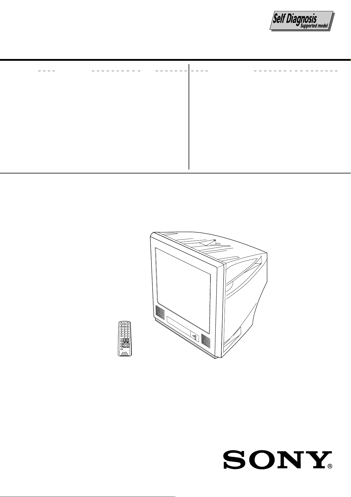
TV
TRINITRON
®
COLOR TV
KV-TG21M70/TG21M90/N
RM-952
Power requirements 110-240 V AC, 50/60 Hz KV-TG21M70
Power consumption (W) Indicated on the rear of the TV
Television system B/G, I, D/K, M
Color system PAL, PAL 60, NTSC3.58, NTSC4.43 SECAM
Stereo/Bilingual system Nicam Stereo/Bilingual B/G, I, D/K; A2 Stereo/Bilingual B/G KV-TG21M90/N
Channel coverage
B/G CATV: S01 to S03, S1 to S41
I UHF: B21 to B68 / CATV: S01 to S03, S1 to S41
D/K VHF: C1 to C12, R1 to R12 / UHF: C13 to C57, R21 to R60
M VHF: A2 to A13
˘ (Antenna) 75-ohm external terminal
Audio output (Speaker) 3W + 3W
Number of terminal
D Video Input: 2* Output: 1 Phono jacks; 1 VP-P, 75 ohms * One input line available
≥ Audio Input: 2* Output: 1 Phono jacks; 500 mVrms * One input line available
2 (Headphone) Output: 1 Stereo minijack KV-TG21M90/N
(Earphone) Output: 1 Monaural minijack KV-TG21M70
Picture tube 21 in.
Tube size (cm) 54 Measured diagonally
Screen size (cm) 51 Measured diagonally
Dimension (w/h/d, mm) 497 x 458 x 487
Mass (kg) 25
SPECIFICATIONS
Note
220-240 V AC, 50/60 Hz KV-TG21M90/N
VHF: E2 to E12 / UHF: E21 to E69 /
CATV: S01 to S03, S1 to S41, Z1 to Z39
UHF: A14 to A79
CATV: A-8 to A-2, A to W+4, W+6 to W+84
CAUTION
SHORT CIRCUIT THE ANODE OF THE PICTURE TUBE AND
THE ANODE CAP TO THE METAL CHASSIS, CRT SHIELD,
OR CARBON PAINTED ON THE CRT, AFTER REMOVING THE
ANODE.
Design and specifications are subject to change without notice.
SAFETY-RELATED COMPONENT WARNING!!
COMPONENTS IDENTIFIED BY SHADING AND MARK ! ON
THE SCHEMATIC DIAGRAMS, EXPLODED VIEWS AND IN
THE PARTS LIST ARE CRITICAL TO SAFE OPERATION.
REPLACE THESE COMPONENTS WITH SONY PARTS
WHOSE PART NUMBERS APPEAR AS SHOWN IN THIS
MANUAL OR IN SUPPLEMENTS PUBLISHED BY SONY.
– 2 –

TABLE OF CONTENTS
KV-TG21M70/TG21M90/N
RM-952
Section Title Page
SELF DIAGNOSTIC FUNCTION ................................... 4
1. GENERAL ................................................................. 7
2. DISASSEMBLY
2-1. Rear Cover Removal ............................................... 11
2-2. Speaker Removal .................................................... 11
2-3. Chassis Assy Removal ............................................ 11
2-4. Service Position ...................................................... 11
2-5. Terminal Bracket Removal ..................................... 11
2-6. Replacement of Parts .............................................. 12
2-6-1. Replacement of Light Guide ........................ 12
2-6-2. Replacement of Power Button ..................... 12
2-7. Picture Tube Removal ............................................. 12
3. SET-UP ADJUSTMENTS
3-1. Beam Landing ......................................................... 14
3-2. Convergence ............................................................ 15
3-3. Focus Adjustment.................................................... 17
3-4. G2 (SCREEN) and White Balance Adjustments ... 17
4. CIRCUIT ADJUSTMENTS
4-1. Adjustment With Commander ................................ 18
4-2. Adjustment Method ................................................ 18
4-3. Picture Quality Adjustment .................................... 24
4-4. Deflection Adjustment ............................................ 24
4-5. A Board Adjustment After IC003 (MEMORY)
Replacement ............................................................ 24
4-6. Picture Distortion Adjustment ................................ 25
Section Title Page
5. DIAGRAMS
5-1. Block Diagram ........................................................ 27
5-2. Circuit Boards Location .......................................... 29
5-3. Schematic Diagram ................................................. 30
(1) A Board Schematic Diagram ............................ 31
(2) A3 Board Schematic Diagram .......................... 33
(3) CV Board Schematic Diagram ......................... 35
(4) F Board Schematic Diagram ............................. 36
5-4. Voltage Measurement ............................................. 39
5-5. Waveforms .............................................................. 42
5-6. Printed Wiring Boards and Parts Location ............. 43
5-7. Semiconductors ....................................................... 47
6. EXPLODED VIEWS
6-1. Picture Tube and Chassis ........................................ 49
7. ELECTRICAL PARTS LIST.................................... 50
– 3 –
KV-TG21M70/TG21M90/N
RM-952
SELF DIAGNOSTIC FUNCTION
The units in this manual contain a self-diagnostic function. If an error occurs, the STANDBY/TIMER lamp will automatically begin to flash.
The number of times the lamp flashes translates to a probable source of the problem. A definition of the STANDBY/
TIMER lamp flash indicators is listed in the instruction manual for the user’s knowledge and reference. If an error
symptom cannot be reproduced, the remote commander can be used to review the failure occurrence data stored in
memory to reveal past problems and how often these problems occur.
1. DIAGNOSTIC TEST INDICATORS
When an errors occurs, the STANDBY/TIMER lamp will flash a set number of times to indicate the possible cause of the
problem. If there is more than one error, the lamp will identify the first of the problem areas.
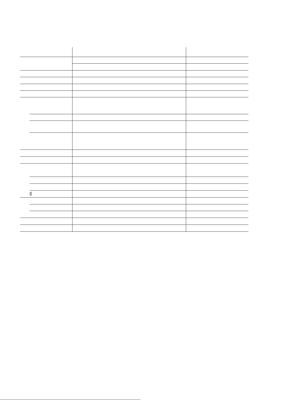
Result for all of the following diagnostic items are displayed on screen. No error has occured if the screen displays a “0”.
Diagnostic
Item
Description
• Power does not
turn on
• +B overcurrent
(OCP)
• Horizontal
deflection
overdrive
• White balance
failure (no
PICTURE)
• Vertical deflection
stopped
• Micro reset
No. of times
STANDBY/TIMER
lamp flashes
Does not light
2 times
4 times
—
Self-diagnostic
display/Diagnostic
result
—
002:000 or
002:001~255
004:000 or
004:001~225
101:00 or
101:001~225
Probable
Cause
Location
• Power cord is not
plugged in.
• Fuse is burned out
F4601 (F)
• H.OUT Q801 is shorted.
(A board)
• -13V is not supplied.
(CV Board)
• IC551 faulty (A board)
• Discharge CRT
(CV Board)
• Static discharge
• External noise
Detected
Symptoms
• Power does not come on.
• No power is supplied to
the TV.
• AC power supply is faulty.
• Power does not come on.
• Load on power line is
shorted.
• Has entered standby state
after horizontal raster.
• Power line is shorted or
power supply is stopped.
• Vertical deflection pulse
is stopped
• Power is shut down
shortly, after this return
back to normal.
• Detect Micro latch up.
Note 1: If a + B overcurrent is detected, stoppage of the vertical deflection is detected simultaneously.
The symptom that is diagnosed first by the microcontroller is displayed on the screen.
Note 2: Refer to screen (G2) Adjustment in section 3-4 of this manual.
– 4 –
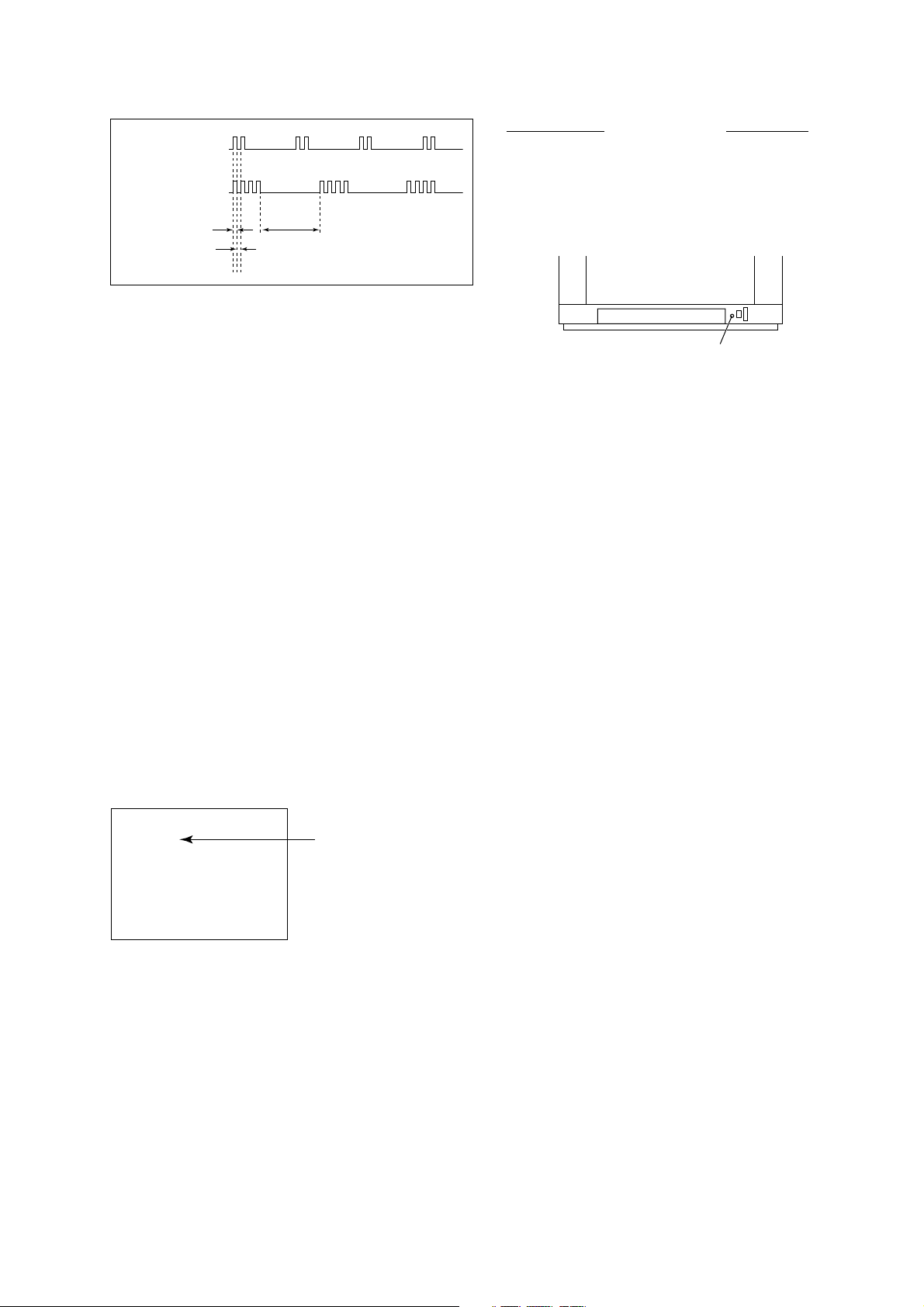
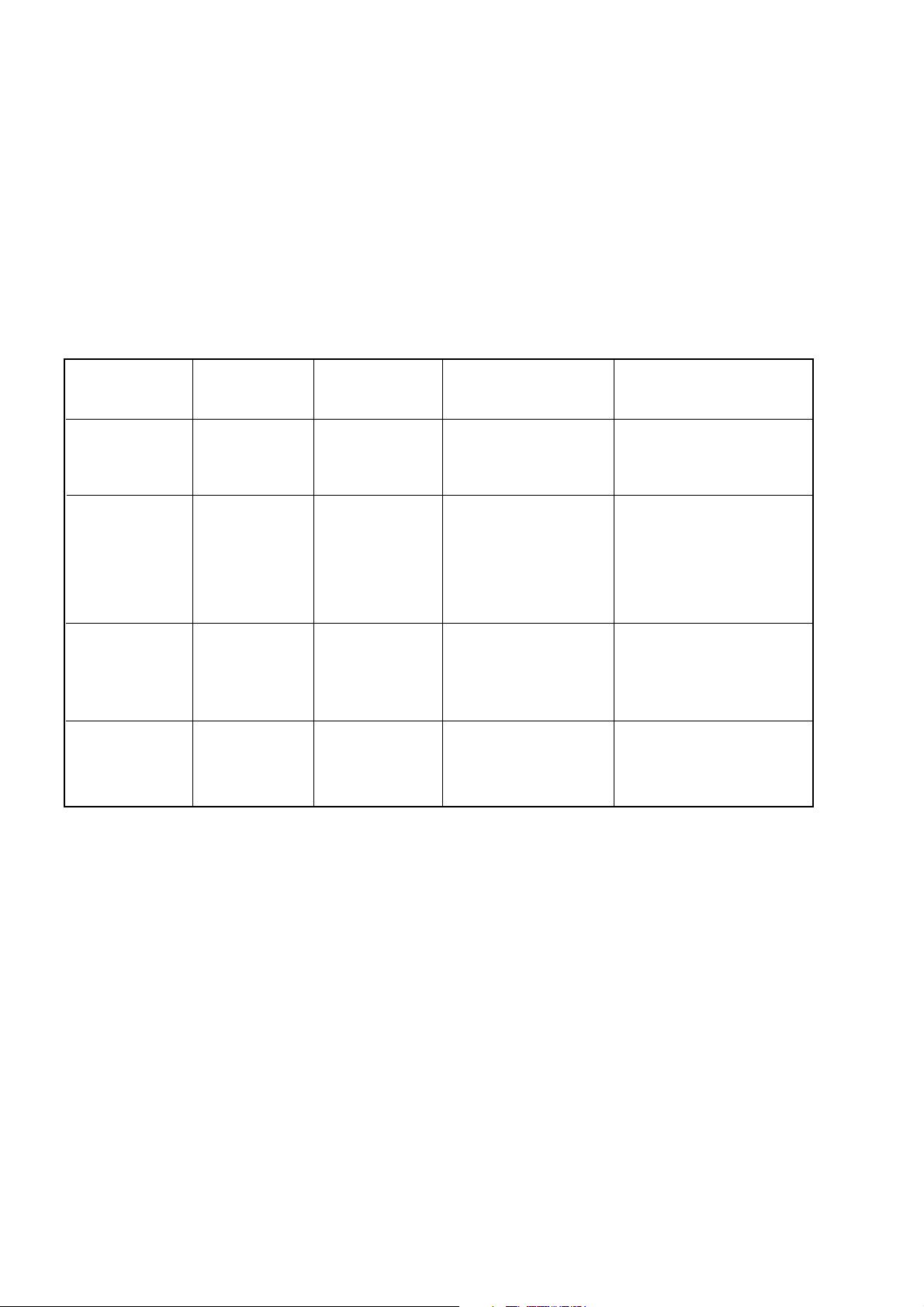
2. DISPLAY OF STANDBY/TIMER LIGHT FLASH COUNT
2 times
KV-TG21M70/TG21M90/N
RM-952
Diagnostic Item Flash Count*
+B overcurrent/overvoltage 2 times
4 times
Lamp ON 0.3 sec.
Lamp OFF 0.3 sec.
Lamp OFF 3 sec.
Vertical deflection stopped 4 times
* One flash count is not used for self-diagnostic.
STANDBY/SLEEP lamp
3. STOPPING THE STANDBY/TIMER FLASH
Turn off the power switch on the TV main unit or unplug the power cord from the outlet to stop the STANDBY/TIMER
lamp from flashing.
4. SELF-DIAGNOSTIC SCREEN DISPLAY
For errors with symptoms such as “power sometimes shuts off” or “screen sometimes goes out” that cannot be confirmed, it is possible to bring up past occurances of failure for confirmation on the screen:
[To Bring Up Screen Test]
In standby mode, press buttons on the remote commander sequentially in rapid succession as shown below:
[Screendisplay] / channel [5] / Sound volume [-] / Power ON
˘
Note that this differs from entering the service mode (mode volume [+]).
Self-Diagnosis screen display
SELF DIAGNOSTIC
002 : 000
004 : 000
101 : 000
Numeral "0" means that no fault has been detected.
– 5 –
KV-TG21M70/TG21M90/N
RM-952
5. HANDLING OF SELF-DIAGNOSTIC SCREEN DISPLAY
Since the diagnostic results displayed on the screen are not automatically cleared, always check the self-diagnostic
screen during repairs. When you have completed the repairs, clear the result display to “0”.
Unless the result display is cleared to “0”, the self-diagnostic function will not be able to detect subsequent faults after
completion of the repairs.
[Clearing the result display]
To clear the result display to “0”, press buttons on the remote commander sequentially as shown below when the
diagnostic screen is being displayed.
Channel [8] / 0
[Quitting Self-diagnostic screen]
To quit the entire self-diagnostic screen, turn off the power switch on the remote commander or the main unit.
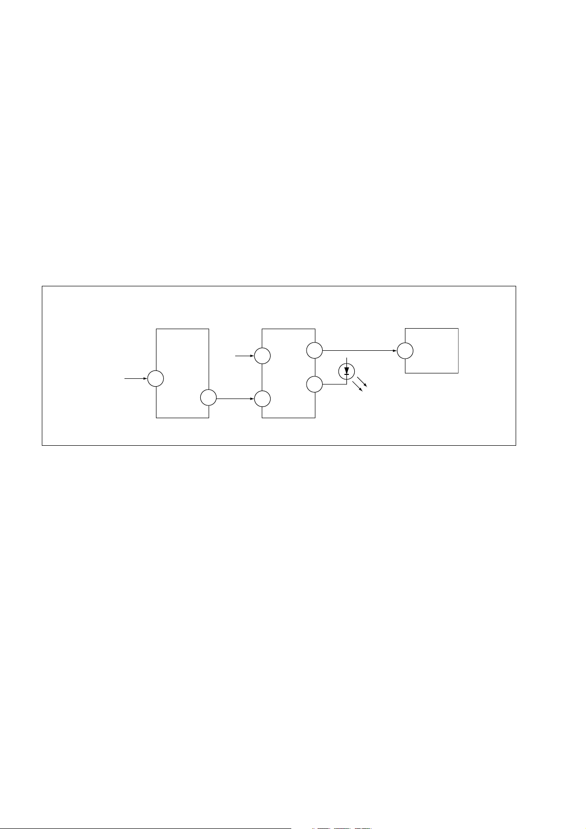
6. SELF-DIAGNOSTIC CIRCUIT
FROM
[+B] Q500
IC301
Y/CHROMA JUNGLE
MP/
50
PROTECT
8
SDA
[V]
D553
IC001
SYSTEM
IO-8DAT B-DAT
17
O-LED
54
IO-SDAT
53
51
IC003
MEMORY
5
[+BovercurrentªOCPº] Occurs when an overcurrent on the +B(135) line is detected by Q500. If Q500 go to
ON and the voltage to pin 50 of IC301 more than 3.5V when V.SYNC is more than
seven verticals in a period, the unit will automatically turn off.
[Verticaldeflectionstopped] Occurs when an absence of the vertical deflection pulse is detected by Pin 17 and
IC001 shut down the power supply.
[Whitebalancefailure] If the RGB levels* do not balance or become low level within 5 seconds, this error
will be detected by IC301. TV will stay on, but there will be no picture.
* (Refers to the RGB levels of the AKB detection Ref pulse that detects IK.)
– 6 –
KV-TG21M70/TG21M90/N
RM-952
A Getting Started
Step 1
b
b
SELECT
PROGR
SELECT
Insert the batteries (supplied) into the remote.
Note
• Do not use old batteries nor use different types of batteries
together.
Step 2
Connect the antenna cable (not supplied) to 8
(antenna input) at the rear of the TV.
Tip
• You can also connect your TV to other optional components.
(See E)
Step 3
Plug in the power cord, then press ! on the TV to
turn it on.
Step 4
Press SELECT and PROGR + on the TV at the same time
for one to two seconds to preset the channels
automatically. (See J)
Tip
• To stop the automatic channel presetting, press SELECT.
Step 5
Press SELECT on the remote until “LANGUAGE/ :
ENGLISH” appears on the screen, then press + or – to
change the on-screen display language.
(KV-TG21M70)
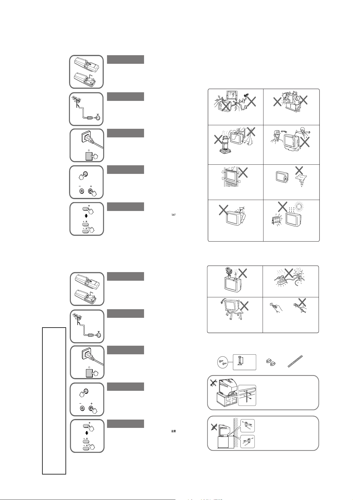
B
WARNING
• Dangerously high voltages are present inside the TV.
• TV operating voltage: 110 – 240 V AC. (KV-TG21M70)
• Do not plug in the power cord until you have completed making all other connections;
otherwise a minimum leakage current might flow through the antenna and other terminals to
ground.
• To avoid battery leakage and damage to the remote, remove the batteries from the remote if
you are not going to use it for several days. If any liquid that leaks from the batteries touches
you, immediately wash it away with water.
For your own safety, do not touch any part of the
TV, the power cord and the antenna cable during
lightning storms.
To prevent fire or shock hazard, do not expose
the TV to rain or moisture.
Do not block the ventilation openings of the TV.
Do not install the TV in a confined space, such
as a bookcase or built-in cabinet.
Do not open the cabinet and the rear cover of the
TV as high voltages and other hazards are
present inside the TV. Refer servicing and
disposal of the TV to qualified personnel.
220 – 240 V AC. (KV-TG21M90/N)
For children’s safety, do not leave children alone
with the TV. Do not allow children to climb onto
it.
Do not operate the TV if any liquid or solid object
falls into it. Have it checked immediately by
qualified personnel only.
Clean the TV with a dry and soft cloth. Do not use
benzine, thinner, or any other chemicals to clean
the TV. Do not scratch the picture tube.
Your TV is recommended for home use only.
Do not use the TV in any vehicle or where it may
be subject to excessive dust, heat, moisture or
vibrations.
A Getting Started
GENERAL
SECTION 1
b
SELECT
PROGR
SELECT
(KV-TG21M90/N)
WARNING (continued)
Step 1
Insert the batteries (supplied) into the remote.
Note
• Do not use old batteries nor use different types of batteries
together.
Do not place any objects on the TV.
Step 2
Connect the antenna cable (not supplied) to 8 at the
rear of the TV.
Tip
• You can also connect your TV to other optional components.
(See E)
Step 3
b
Plug in the power cord, then press ! on the TV to
turn it on.
Install the TV on a stable TV stand and floor
which can support the TV set weight. Ensure that
the TV stand surface is flat and its area is larger
than the bottom area of the TV.
C
Securing the TV
To prevent the TV from falling, use the supplied screws, clamps and band to secure the TV
20 mm
screws clamps band
3.8 mm
Step 4
Press SELECT and PROGR + on the TV at the same time
for one to two seconds to preset the channels
automatically. (See J)
Tip
• To stop the automatic channel presetting, press SELECT twice.
Step 5
Press SELECT on the remote until “LANGUAGE/ :
ENGLISH” appears on the screen, then press + or – to
change the on-sceen display language.
Do not plug in too many appliances to the same
power socket. Do not damage the power cord.
Pull the power cord out by the plug. Do not pull
the power cord itself. Even if your TV is turned
off, it is still connected to the AC power source
(mains) as long as the power cord is plugged in.
Unplug the TV before moving it or if you are not
going to use it for several days.
Screw the band to the TV stand and to the
provided hole at the rear of your TV.
or
(1) Put a cord or chain through the
clamps.
(2) Screw one clamp to a wall or pillar
and the other clamp to the provided
hole at the rear of your TV.
.
The operating instruction mentioned here are partial abstracts
from the Operating Instruction Manual. The page numbers of
the Operating Instruction Manual remain as in the manual.
– 7 –
Note
• Use only the supplied screws. Use of other screws may damage the TV.
KV-TG21M70/TG21M90/N
RM-952
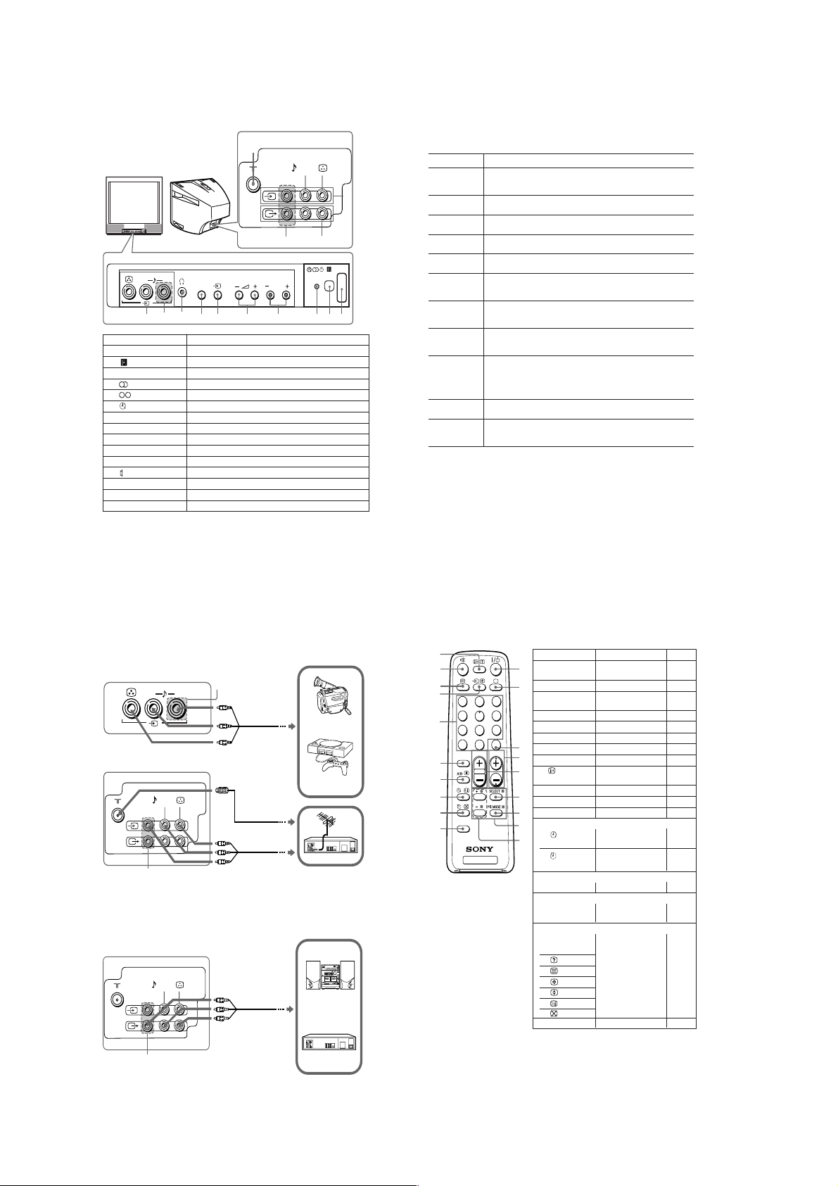
D
TV front and rear panels
TV front panel
(MONO)
R
L
8
9
★
Button Function
1
! Turn off completely or turn on the TV.
2
3
1 Standby indicator.
3
3
3
4
PROGR +/– Select program number.
5
2 +/– * Adjust volume.
6
t Select TV or video input.
7
SELECT Select the desired item.
8
i Headphone terminal. (KV-TG21M90/N)
8
9, qa
t Video input terminal.
0
8 Antenna terminal.
qs
T Monitor output terminal.
* You can also use the 2 +/– buttons on the TV to work as the +/– buttons on the remote.
★
The R (audio input) jacks are only available for KV-TG21 only.
TV rear panel
0
L(MONO)R
★
SELECT
6
7
Remote control sensor.
Stereo/bilingual indicator. (KV-TG21M90 only)
Bilingual indicator. (KV-PG14M72 only)
Wake Up indicator.
Earphone terminal. (KV-TG21M70)
PROGR
4
5
3
F
Troubleshooting
If you find any problem while viewing your TV, please check the following
guide. If any problem persists, contact your Sony dealer.
Symptom Solutions
Snowy picture,
noisy sound
qa
qs
!
1
2
Good picture,
noisy sound
No picture,no sound
Good picture, no sound
Dotted lines or stripes
Double images or
“ghosts”
No color
Abnormal color
patches
The 1 (standby)
indicator on your TV
flashes red several
times after every
three seconds.
TV cabinet creaks.
A "boom" sound is
heard when the TV is
turned on.
• Check the antenna cable and connection on the TV, VCR and on the wall.
• Preset the channel manually again. (See J)
• Check the antenna setup. Contact a Sony dealer for advice.
• Select the appropriate TV system. (See J)
• Press A/B until the sound is optimal. (KV-TG21M90 only)
• Check the power cord, antenna and the VCR connections.
• Press ?/1 (power) or ! (main power) to turn on the TV.
• Press 2 + to increase the volume level.
• Press % to cancel the muting.
• Do not use a hair dryer or other equipment near the TV.
• Check the antenna setup. Contact a Sony dealer for advice.
• Use the fine tuning ("FINE") function. (See J)
• Turn off or disconnect the booster if it is in use.
• Check the antenna setup. Contact a Sony dealer for advice.
• Select the appropriate color system. (See J)
• Adjust the color level. (See K)
• Check the antenna setup. Contact a Sony dealer for advice.
• Keep external speakers or other electrical equipment away from the TV.
Press ! (main power) to turn off the TV for about 15 minutes, then turn
it on again to demagnetize the TV.
• Count the number of times the 1 (standby) indicator flashes. Press !
(main power) to turn off your TV. Contact your nearest Sony service
center.
• Changes in room temperature sometimes make the TV cabinet expand or
contract, making a noise. This does not indicate a malfunction.
• The TV's demagnetizing function is working. This does not indicate a
malfunction.
E
Connecting optional components
Connecting to the video input terminal ( t )
TV front panel
TV rear panel
(MONO)
L
L(MONO)R
★
R
Audio/Video cable
(not supplied)
Antenna cable
(not supplied)
Audio/Video cable
(not supplied)
Camcorder
Video game
equipment
VCR
★
Note
• Do not connect video equipment to t (video input) at the front and the rear of your TV at
the same time; otherwise the picture will not be displayed properly on the screen.
Connecting to the monitor output terminal (T)
TV rear panel
L(MONO)R
Audio/Video cable
(not supplied)
Audio system
H
Remote control
0
qa
qs
qd
qf
qg
1
4
7
-
SOUND
MODE
3
2
6
5
9
8
JUMP
0
PROGR
2
qh
qj
qk
FAVORITE
ql
TV
Button Function
1
?/1 Turn off temporarily or
1
2
a
2
3
JUMP Jump to previous
4
PROGR +/– Select program number.
5
2 +/–
6
SELECT Select the desired item.
3
7
PIC MODE Select picture mode.
4
9
+/– Adjust items.
0
5
qa
%
6
qd
t
qf
0 – 9, ÷ Input numbers.
7
Timer operations
8
qj
9
qk
Sound mode operations (KV-TG21M90 only)
qg
SOUND MODE Select sound mode.
Stereo/bilingual operations (KV-TG21M90 only)
qh
A/B Select stereo/bilingual
Teletext operations
8
x (red, green,
yellow, blue)
0
qs
qd
qh
qj
qk
ql
FAVORITE
turn on the TV.
Display the TV program.
program number.
Adjust volume.
Display on-screen
information.
Mute the sound.
Select TV or video input.
Set TV to turn on
automatically.
Set TV to turn off
automatically.
mode.
Not function for your TV.
Not function for your TV.
See
–
–
–
–
–
–
K
–
–
–
–
–
I
I
K
M
–
–
★
★
The R (audio input) jacks are only available for KV-TG21 only.
VCR
– 8 –
KV-TG21M70/TG21M90/N
RM-952
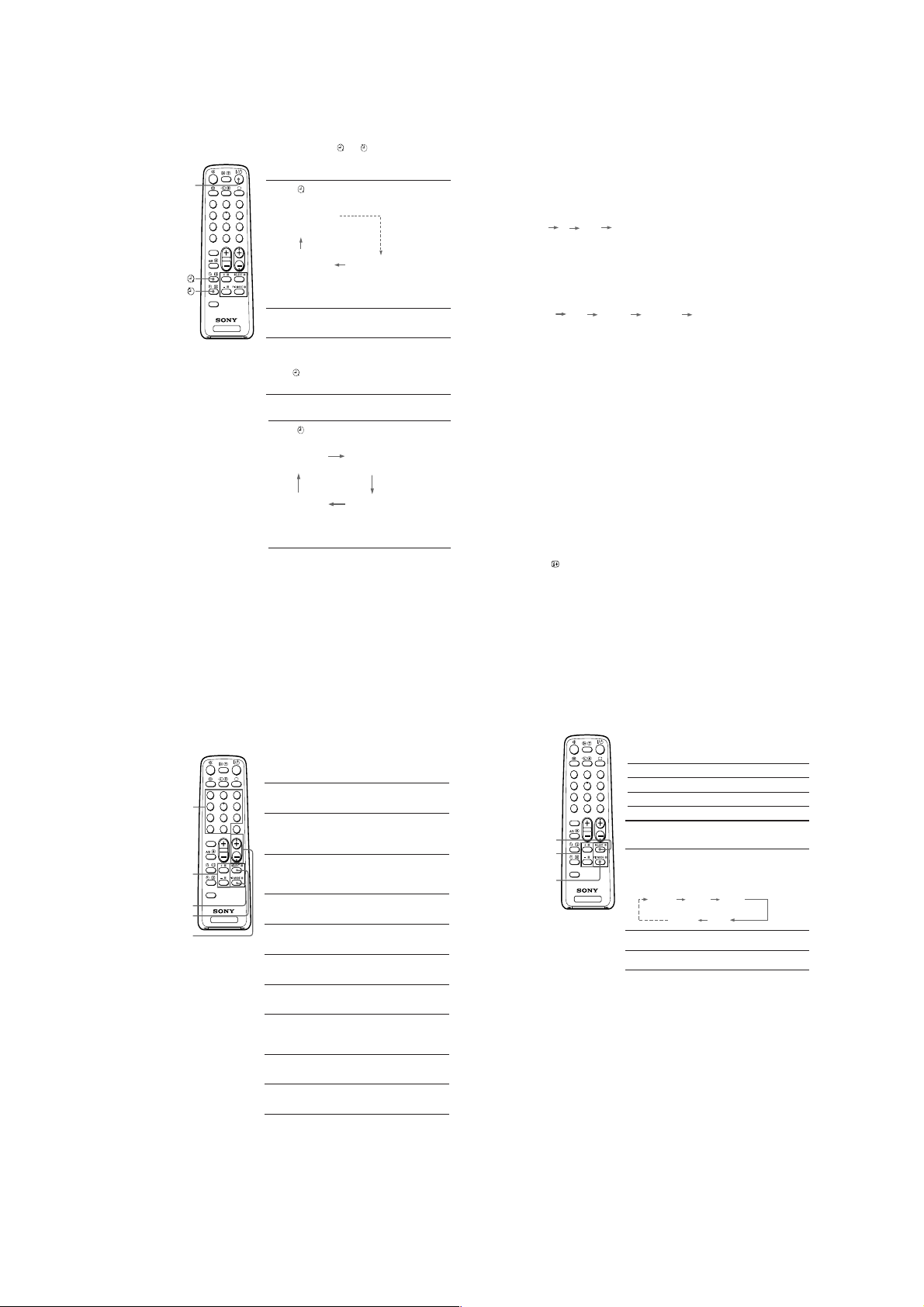
I
Setting the timers
You can turn on and off your TV by using the and buttons respectively.
Setting the Wake Up timer
\/1
-
SOUND
MODE
FAVORITE
1
2
4
5
7
8
0
2
TV
Press until the desired period of time appears
1
on the screen.
3
WAKE UP TIMER:0H10M
6
(After 10 minutes)
9
JUMP
PROGR
WAKE UP TIMER:OFF
(No Wake Up timer) (After 12 hours)
The Wake Up timer starts immediately after you
have set it.
Select the program number or video input you
2
want to wake up to.
Press \/1, or set the Sleep timer if you want the
3
TV to turn off automatically.
indicator on the TV lights up orange when
The
the TV goes into standby mode.
WAKE UP TIMER:12H00M
Setting the Sleep timer
Press until the desired period of time appears
on the screen.
SLEEP TIMER:30M SLEEP TIMER:60M
(After 30 minutes)
SLEEP TIMER:OFF SLEEP TIMER:90M
(No Sleep timer)
The Sleep timer starts immediately after you have
set it.
Notes
• You can also cancel the Wake Up and Sleep timers by turning off the TV’s main power.
• If no buttons or controls are pressed for more than two hours after the TV is turned on using
the Wake Up timer, the TV automatically goes into standby mode.
(After 60 minutes)
(After 90 minutes)
Presetting channels (continued)
To change the TV system setting
If the picture or sound is abnormal when receiving programs through the 8 (antenna)
terminal
(1) Press SELECT until “TV SYS” appears on the screen.
(2) Press + or – to select the appropriate TV system until the picture or sound quality
is optimal.
B/G I D/K M
To change the color system setting
If the color is abnormal when receiving programs through the 8 (antenna) terminal
or the t (video input) terminal
(1) Press SELECT until “COLOR SYS” appears on the screen.
(2) Press + or – to select the appropriate color system until the color is optimal.
AUTO PAL SECAM NTSC3.58 NTSC4.43
To skip program numbers
(1) Press PROGR +/– or the number buttons until the unused or unwanted program
number appears on the screen.
(2) Press SELECT until “MANUAL PROGRAM” appears on the screen.
(3) Press + or – once to enter the “MANUAL PROGRAM” mode.
(4) Press PIC MODE to skip the unused or unwanted program number.
(5) Press SELECT to exit the “MANUAL PROGRAM” mode.
Note
• To restore the skipped program number again, preset the channel automatically or manually.
To use the fine tuning function
The fine tuning (FINE) function may help to reduce the following problems:
double images and lines moving across the TV screen.
You can use the fine tuning function as below:
(1) Select the program number you want to adjust.
(2) Press SELECT until “MANUAL PROGRAM” appears on the screen.
(3) Press + or – once to enter the “MANUAL PROGRAM” mode.
(4) Press
to display “FINE” on the screen.
(5) Press + or – continuously until the above problems are minimized.
The + or – icon on the screen flashes while tuning.
(6) Press SELECT to exit the “MANUAL PROGRAM” mode.
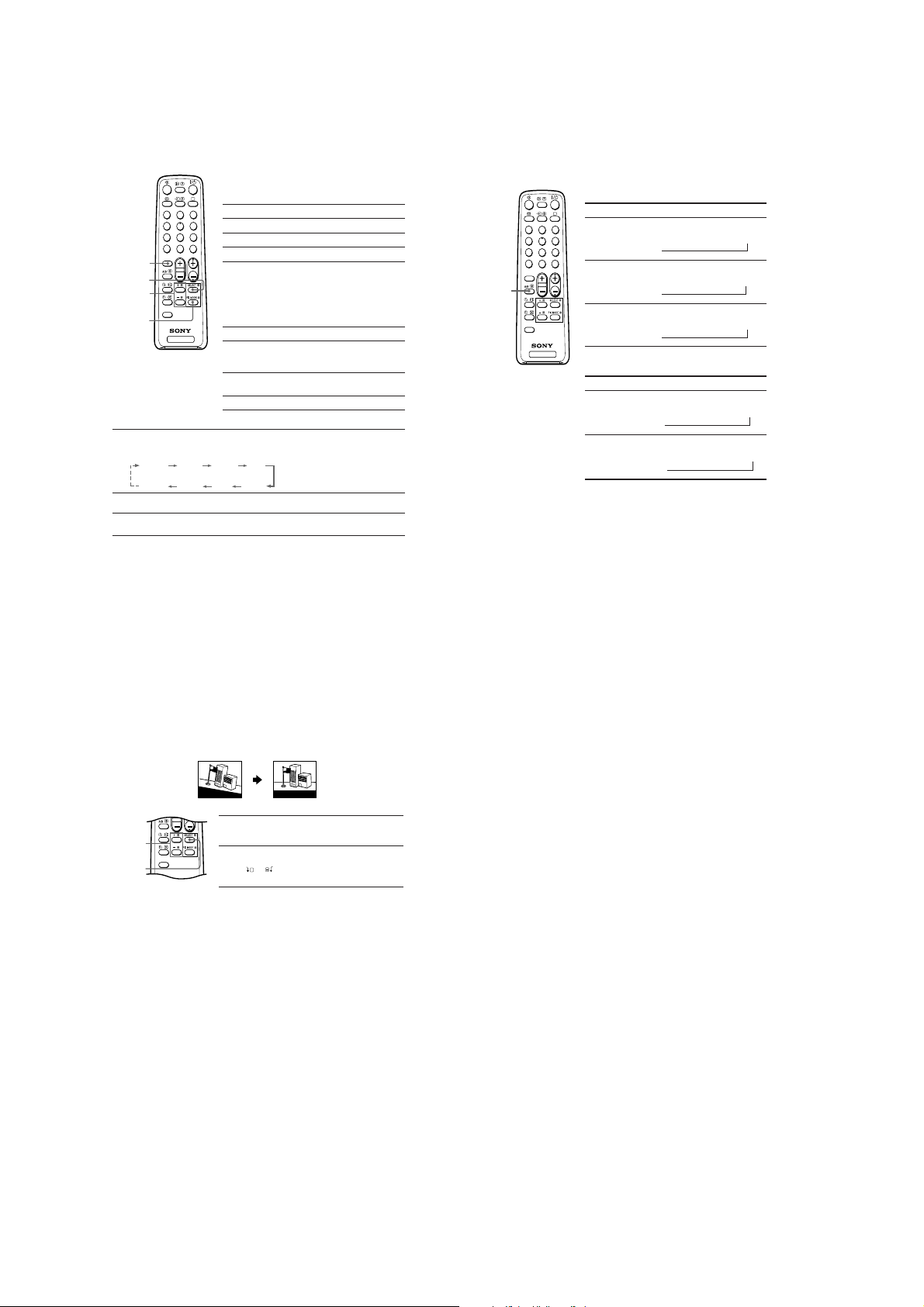
J
Presetting channels
You can automatically preset up to 100 TV channels in numerical sequence
from program number 1, or manually preset desired channels and channels
that cannot be preset automatically.
Presetting channels automatically
from a specified program number
Press SELECT until “AUTO PROGRAM” appears
3
1
2
1
Number
buttons
+ or –
PIC MODE
SELECT
PROGR +/–
4
7
-
SOUND
MODE
FAVORITE
5
8
0
2
TV
on the screen.
6
9
Press + or – once to enter the “AUTO
2
JUMP
PROGRAM” mode.
PROGR
The on-screen display will start flashing.
Press PROGR +/– or the number buttons until
3
the desired program number appears on the
screen.
Press + or – to start presetting channels
4
automatically.
Presetting channels manually
Press SELECT until “MANUAL PROGRAM”
1
appears on the screen.
Press + or – once to enter the “MANUAL
2
PROGRAM” mode.
Press PROGR +/– or the number buttons until
3
the desired program number appears on the
screen.
Press + or – until the desired channel picture
4
appears on the screen.
To preset other channels manually, repeat steps
5
3 to 4.
K
Customizing the picture
You can customize the picture by selecting the picture mode or by adjusting its
settings.
(KV-TG21M70)
Selecting the picture mode
Press PIC MODE to select the desired picture mode.
Select To
3
1
2
“DYNAMIC” view high contrast pictures.
6
4
5
9
7
8
“STANDARD” view normal contrast pictures.
JUMP
-
0
SOUND
MODE
SELECT
+ or –
PIC MODE
Notes
•“HUE” can be adjusted for the NTSC color system only.
• Reducing “SHARP” can also reduce picture noise.
FAVORITE
“SOFT” view mild pictures.
PROGR
2
Adjusting the picture setting
1Press SELECT until the desired setting appears.
Each time you press SELECT, the setting item will
change as follows:
TV
PICTURE COLOR BRIGHT
HUE
SHARP
Press + or – to adjust the item.
2
To adjust other items, repeat steps 1 to 2.
3
– 9 –
KV-TG21M70/TG21M90/N
NICAM MAIN
(Main sound)
NICAM SUB
(Sub sound)
MONO
(Regular sound)
tt
NICAM MAIN
(Main sound)
MONO
(Regular sound)
t
t
RM-952
K
Customizing the picture and sound
(KV-TG21M90/N)
You can customize the picture and sound by selecting the picture and sound
modes or by adjusting its settings.
3
1
2
6
4
5
9
7
8
JUMP
-
0
SOUND
PROGR
2
MODE
SOUND
MODE
SELECT
+ or –
FAVORITE
PIC MODE
TV
Adjusting the picture and sound settings
Press SELECT until the desired setting appears.
1
Each time you press SELECT, the setting item will change as follows:
PICTURE COLOR BRIGHT HUE
BALANCE TREBLE BASS
Press + or – to adjust the item.
2
To adjust other items, repeat steps 1 to 2.
3
Notes
•“BASS”, “TREBLE” and “BALANCE” can be adjusted for KV-TG21M90 only.
•“HUE” can be adjusted for the NTSC color system only.
• Reducing “SHARP” can also reduce picture noise.
Selecting the picture mode
Press PIC MODE to select the desired picture mode.
Select To
“DYNAMIC” view high contrast pictures.
“STANDARD” view normal contrast pictures.
“SOFT” view mild pictures.
Selecting the sound mode
B KV-TG21M90 only
Press SOUND MODE to select the desired sound
mode.
Select To
“9 DYNAMIC” listen to dynamic and clear
“9 DRAMA” listen to sound that emphasizes
“9 SOFT” listen to soft sound.
SHARP
sound that emphasizes the low
and high sound.
vocals and background music.
M
Enjoying stereo or bilingual
programs
You can enjoy stereo sound or bilingual programs of NICAM and A2 stereo
systems by using the A/B button.
(KV-TG21M90/N)
When receiving a NICAM program
Broadcasting On-screen display (Selected sound)
NICAM
3
1
2
stereo
6
4
5
(KV-TG21M90 only)
9
7
8
JUMP
-
0
SOUND
MODE
NICAM
PROGR
2
bilingual
NICAM
(Stereo sound)
t
t
MONO
(Regular sound)
A/B
FAVORITE
NICAM
monaural
TV
When receiving an A2 program
Broadcasting On-screen display (Selected sound)
A2
stereo
A2
bilingual
Notes
• If the sound is distorted when receiving a monaural program through the 8 (antenna)
terminal, press A/B repeatedly until “MONO” appears on the screen. To cancel the monaural
sound setting, press A/B again until “AUTO” appears on the screen.
KV-TG21M90 only
• If the stereo sound is noisy when receiving a stereo program, select “MONO”. The sound
becomes monaural, but the noise is reduced.
• Before receiving a NICAM stereo program in China, please check the NICAM broadcast
condition in your area. When receiving a NICAM stereo program, the receiving conditions
might vary depending on area. In addition, different strength of the NICAM broadcast signal
might affect the receiving quality.
MONO
(Regular sound)
t
MAIN
(Main sound)
t
STEREO
t
(Stereo sound)
t
(Sub sound)
SUB
L
Adjusting the picture position
B
KV-TG21M90/N only
If the picture is slanting, you can adjust the picture position using the
“PIC ROTATION” function until it is optimal.
Slanting Optimal
G
o
o
d
m
o
r
n
i
n
g
!
Press SELECT repeatedly until “PIC ROTATION”
1
+ or –
FAVORITE
SELECT
Note
• To reduce the slanting picture, keep external speakers or other electrical equipment away
from the TV.
appears on the screen.
Press + or – to adjust the picture position.
2
The
adjusting.
Good morning!
+
or icon on the screen flashes while
– 10 –
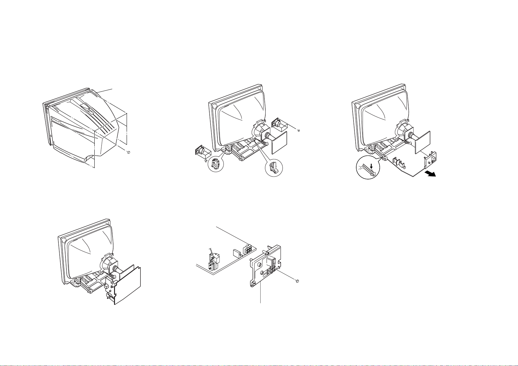
1 Eight screws
(+BVTP 4 × 16)
1 Rear Cover
2-1. REAR COVER REMOVAL
1 Four screws
(BVTP 3 × 12)
CRT SUPPORT BLOCK
1 Four screws
(BVTP 3 × 12)
Push claw
1 One screw
(+BVTP 4 × 16)
2 Terminal Bracket
– 11 –
SECTION 2
DISASSEMBLY
2-2. SPEAKER REMOVAL
2-3. CHASSIS ASSY REMOVAL
2-4. SERVICE POSITION
Caution:
standing position.
Note:
placing the chassis into Service Position.
Do not take out CRT support block while TV set in
Undress necessary wires that creates tension while
2-5. TERMINAL BRACKET REMOVAL
KV-TG21M70/TG21M90/N
RM-952
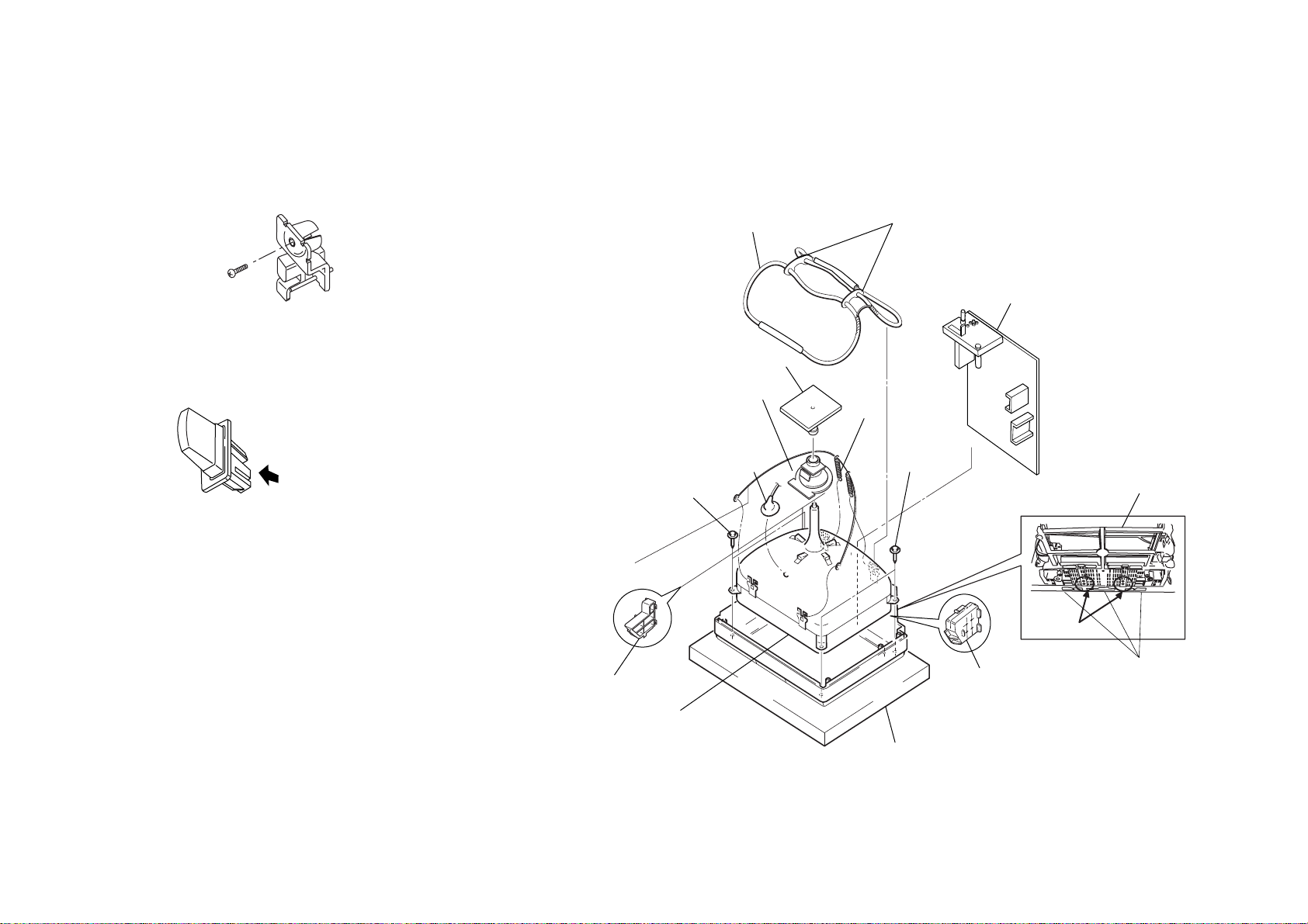
KV-TG21M70/TG21M90/N
One screw
(+BVTP 3 × 12)
1 Push to direction of arrow
and remove
9 Demagnetic coil
!™ Two screws
(Tapping 5+
Crown Washer)
Tension
spring
4 Chassis assy
5 Deflection
yoke
3 CV board
2 Anode
cap
!¡ Coating earth assy
!£ Picture tube
1 Cushion
!™
Two screws
(Tapping 5 +
Crown Washer)
8
Holder DGC
6 PWB Bracket
7 CRT Support Block
7 CRT Support Block
Screw Location
Beznet Hook
!º
2-6. REPLACEMENT OF PARTS
For replacements of light guide,unscrew them,
exchange with new parts and fix them with
screws respectively.
2-7. PICTURE TUBE REMOVAL
Note:
• Please make sure the TV set is not in standing position before removing necessary
CRT support located on bottom right and left.
RM-952
2-6-1. Replacement of Light Guide
2-6-2. Replacement of Power Button
– 12 –
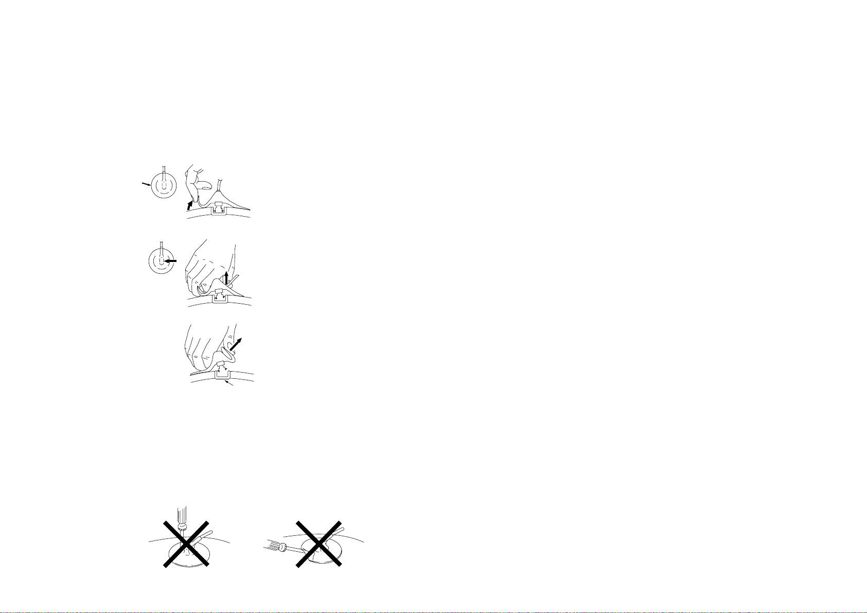
• REMOVAL OF ANODE-CAP
a
a
b
b
Anode button
c
NOTE : After removing the anode, short circuit the anode of the picture tube and
the anode cap to the metal chassis, CRT shield or carbon paint on the
CRT.
• REMOVING PROCEDURES
1 Turn up one side of the rubber cap in the direction indicated by the arrow a.
– 13 –
2 Using a thumb pull up the rubber cap firmly in the direction indicated by the arrow b.
3 When one side of the rubber cap is separated from the anode button, the anode-cap
can be removed by turning up the rubber cap and pulling it up in the direction of the
arrow c.
• HOW TO HANDLE AN ANODE-CAP
1 Do not damage the surface of anode-caps with sharp shaped objects.
2 Do not press the rubber too hard so as not to damage the inside of anode-cap.
A metal fitting called the shatter-hook terminal is built into the rubber.
3 Do not turn the foot of rubber over too hard.
The shatter-hook terminal will stick out or damage the rubber.
KV-TG21M70/TG21M90/N
RM-952
KV-TG21M70/TG21M90/N
RM-952
SECTION 3
SET-UP ADJUSTMENTS
The following adjustments should be made when a complete
realignment is required or a new picture tube is installed.
These adjustments should be performed with rated power
supply voltage unless otherwise noted.
Controls and switches should be set as follows unless otherwise
noted:
PICTURE control ........................................................... normal
BRIGHTNESS control................................................... normal
................................................................................................................................................................................................................................
Preparation :
In order to reduce the influence of geomagnetism on the
set's picture tube, face it east or west.
Switch on the set's power and degauss with the degausser.
Perform the adjustments in the following order :
1. Beam Landing
2. Convergence
3. Focus
4. White Balance
Note : Test Equipment Required.
1. Pattern Generator
2. Degausser
3. Oscilloscope
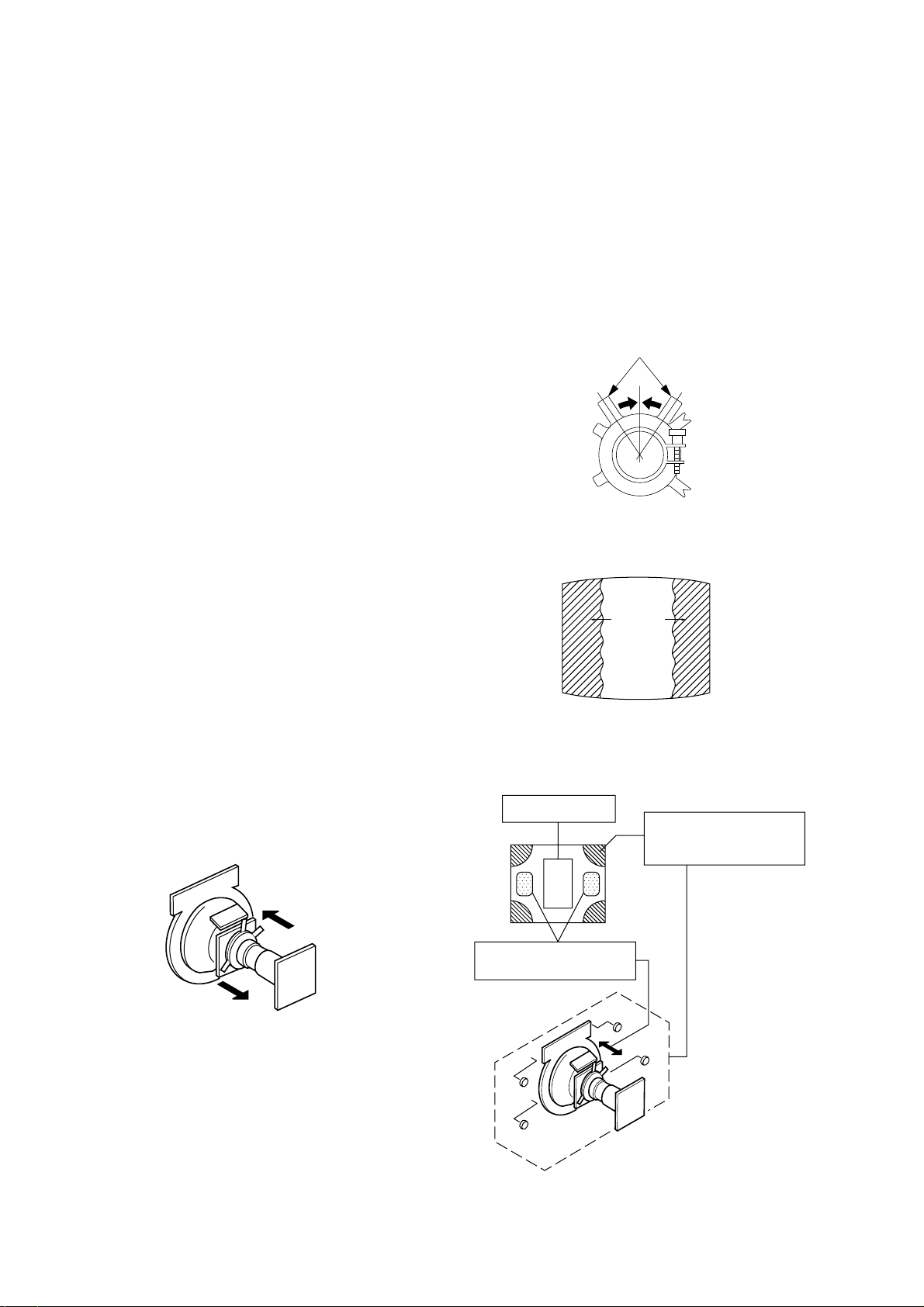
Purity control
3-1. BEAM LANDING
1. Input a white signal with the pattern generator.
Contrast
Brightness
2. Set the pattern generator raster signal to a green raster.
3. Move the deflection yoke to the rear and adjust with the
purity control so that the green is at the center and the blue
and the red take up equally sized areas on each side.
(See Figures 3-1 through 3-4.)
4. Move the deflection yoke forward and adjust so that the
entire screen is green. (See Figure 3-1.)
5. Switch the raster signal to blue, then to red and verify the
condition.
6. When the position of the deflection yoke has been decided,
fasten the deflection yoke with the screws and DY spacers.
7. If the beam does not land correctly in all the corners, use a
magnet to adjust it.
(See Figure 3-4.)
}
normal
Fig. 3-2
Blue
Red
Green
Fig. 3-3
Fig. 3-1
Purity control
corrects this area.
b
c
Deflection yoke positioning
corrects these areas.
a
d
a
d
Fig. 3-4
Disk magnets or rotatable
disk magnets correct these
areas (a-d).
b
c
– 14 –
KV-TG21M70/TG21M90/N
R
R
G
G
B
B
a
a
b
b b
RM-952
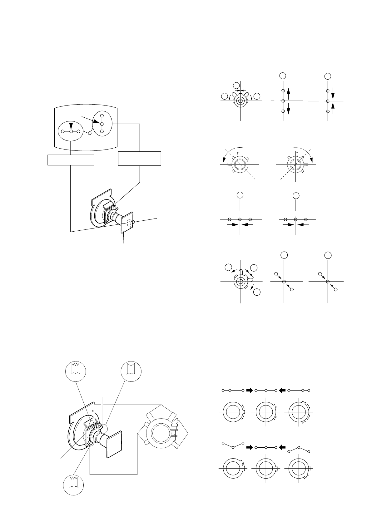
3-2. CONVERGENCE
Preparation :
• Before starting this adjustment, adjust the focus, horizontal
size and vertical size.
• Receive dot/hatch signal.
• Pic mode: Soft.
(1) Horizontal and Vertical Static Convergence
Center dot
R G B
H. STAT VR
R
G
B
V. STAT
Magnet
RV702
H. STAT
• Operation of V. Stat magnet
If the V. Stat magnet is moved in the "a" and "b" arrows, the
red, green and blue dots move as shown below.
1
2
a
a
RGGBB
b
b
R
CV Board
1. (Moving vertically), adjust the V.STAT magnet so that the
red, green and blue dots are on top of each other at the
center of the screen.
2. (Moving horizontally), adjust the H.STAT VR control so
that the red, green and blue dots are on top of each other at
the center of the screen.
3. If the H.STAT variable resistor cannot bring the red, green
and blue dots together at the center of the screen, adjust the
horizontal convergence with the H.STAT variable resistor
and the V.STAT magnet in the manner given below.
(In this case, the H.STAT variable resistor and the V.STAT
magnet influence each other, so be sure to perform adjustments while tracking.)
BMCPurity
BMC (Hexapole)
Purity
3
b
a
a
R
B
G
b
B
4 BMC (Hexapole) Magnet.
If the red, green and blue dots are not balanced or aligned,
then use the BMC magnet to adjust in the manner described
below.
RG B R G B R GB
b
G
R
DY pocket
V.STAT
V.STAT
RB
G
RG
GB
RB
– 15 –
KV-TG21M70/TG21M90/N
RM-952
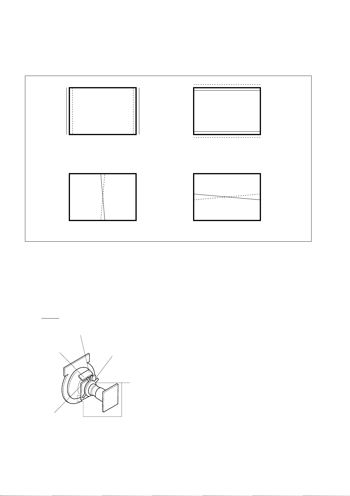
(2) Dynamic Convergence Adjustment
Preparation:
Before starting this adjustment, adjust the horizontal static
convergence and the vertical static convergence
RB
B
R
TLH TLV
RB
R
B
YCH XCV
TLH Insert TLH Correction Plate to DY Pocket (Left or
Right)
YCH Rotate YCH VOL on DY
TLV Rotate TLV VOL ON DY
XCV Rotate XCV Adj core on DY
ON DY:
YCH
TLV
DY pocket
DY pocket
XCV
– 16 –
KV-TG21M70/TG21M90/N
RM-952
(3) Screen-corner Convergence
ba
a-d : screen-corner
misconvergence
cd
Fix a Permalloy assy
corresponding to the
misconverged areas
a
d
a to d : Permalloy assembly
b
c
3-3. FOCUS ADJUSTMENT
FOCUS adjustment should be completed before W/B adjustment.
1. Receive digital monoscope pattern.
2. Set "Picture Mode" to "DYNAMIC".
3. Adjust focus VR so that the center of screen becomes
just focus.
4. Change the receiving signal to white pattern and blue back.
5. Confirm magenta ring is not noticeable. Incase magenta is
very obvious, adjust focus VR to take balance of magenta
ring and focus.
3-4. G2 (SCREEN) AND WHITE BALANCE
ADJUSTMENTS
1. G2 (SCREEN) ADJUSTMENT
1) Set the PICTURE to normal.
2) Put to VIDEO input mode without signals.
3) Connect R, G and B of the CV board cathode to the
oscilloscope.
4) Adjust BRIGHTNESS to obtain the cathode voltage to the
value below.
5) Adjust G2 (screen) on the FBT until picture shows the point
before cut off.
Cathode setting voltage:
175 V ± 2 (VDC)
0 V
2.a). WHITE BALANCE ADJUSTMENT
1) Set to Service Mode (Refer Section 4-1: ADJUSTMENTS
WITH COMMANDER).
2) Input white raster signal.
3) Set ABL (49) and VP2 (IF) service mode to 00.
4) Set Picture to DYNAMIC.
5) Select RDR (0B) with [1] and [4], and set the level to 25
with [3] and [6] for best white balance.
6) Select GDR (0C) and BDR (0D) with [1] and [4], and adjust
the level with [3] and [6] for the best white balance.
7) Write into the memory by pressing [MUTING] then [0].
8) Set back ABL (49) and VP2 (IF) service mode to original data.
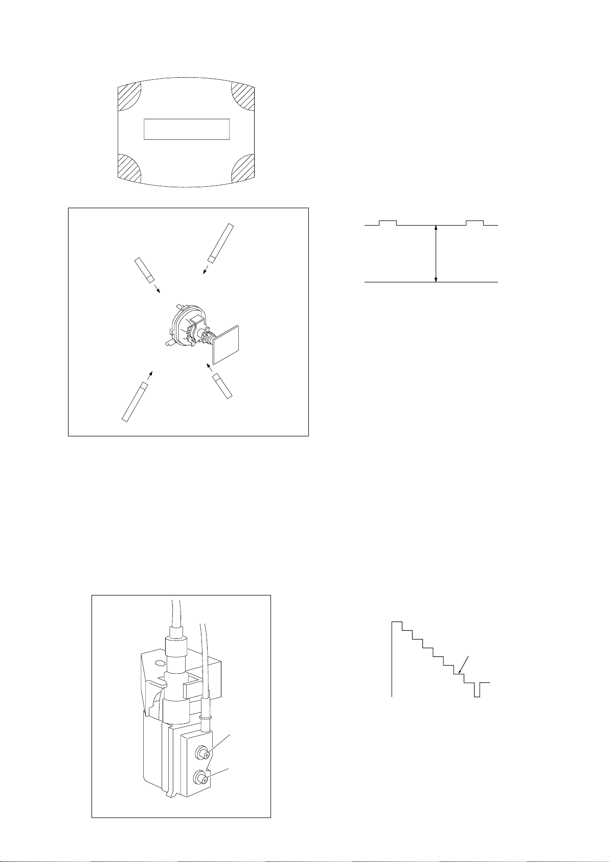
2.b).SUB BRIGHT ADJUSTMENT
1) Set to service mode.
2) Set ABL (49) and VP2 (IF) service mode to 00
3) Input a staircase signal of black to white from the pattern
generator.
4) BRIGHTNESS ....50%.
PICTURE ............MINIMUM
5) Select OE (SBR) with [1] and [4], and adjust OE (SBR) level
with [3] and [6] so that the second stripe from the right is
dimly lit.
6) Write into the memory by pressing [MUTING] then [0].
7) Set back ABL (49) and VP2 (IF) service mode to original
data.
FOCUS
SCREEN
FLYBACK TRANSFORMER (T503)
White
second from the right
Black
– 17 –
 Loading...