

Page 1
REVISION HISTORY
AG-3E
CHASSIS
MODEL
KV-EX29M61
NO DATE DESCRIPTION OF REVISION
PA RT NO. : 9-872-267-01
Page 2
SERVICE MANUAL
AG-3E
CHASSIS
MODEL COMMANDER DEST. CHASSIS NO.
KV-EX29M61 RM-964 Singapore SCC-U37B-A
MODEL COMMANDER DEST. CHASSIS NO.
DRC-MF
1
2
3
4
5
6
7
8
9
JUMP
0
SOUND
FAVORITE
SURROUND
MODE
MENU
PIC MODE
ENTER
PROGR
RESET
TRINITRON
®
COLOR TV
Page 3
KV-EX29M61
RM-964
Power requirements 110-240 V AC, 50/60 Hz
Power consumption (W) Indicated on the rear of the TV
Television system B/G, I, D/K, M
Color system PAL, PAL 60, SECAM, NTSC4.43, NTSC3.58
Stereo/Bilingual system NICAM Stereo/Bilingual B/G, I, D/K; A2 Stereo/Bilingual B/G
Teletext Language English, Arabic, French
Channel coverage
B/G VHF: E2 to E12 / UHF: E21 to E69 / CATV: S01 to S03, S1 to S41
I UHF: B21 to B68 / CATV: S01 to S03, S1 to S41
D/K VHF: C1 to C12, R1 to R12 / UHF: C13 to C57, R21 to R60
M VHF: A2 to A13 / UHF: A14 to A79 /
˘ (Antenna) 75-ohm external terminal
Audio output (Speaker) 8W + 8W
Number of terminal
D (Video) Input: 4 Output: 1 Phono jacks; 1 VP-P, 75 ohms
≥ (Audio) Input: 4 Output: 1 Phono jacks; 500 mVrms
2 (Headphones) Output: 1 Stereo minijack
Picture tube 29 inch
Tube size (cm) 72 Measured diagonally
Screen size (cm) 68 Measured diagonally
Dimension (w/h/d, mm) 772 x 576 x 516
Mass (kg) 51
SPECIFICATIONS
Note
CATV: S01 to S03, S1 to S41, Z1 to Z39
CATV: A-8 to A-2, A to W+4, W+6 to W+84
(S Video) Input: 2 Y : 1 Vp-p, 75 ohms,
unbalanced, sync
negative
C : 0.286 Vp-p, 75 ohms
(Component Video)
Input: 1 Phono jacks;
Y : 1 Vp-p, 75 ohms,
sync negative
B : 0.7 Vp-p, 75 ohms
C
R : 0.7 Vp-p, 75 ohms
C
Audio : 500 mVrms
CAUTION
SHORT CIRCUIT THE ANODE OF THE PICTURE TUBE AND
THE ANODE CAP TO THE METAL CHASSIS, CRT SHIELD,
OR CARBON PAINTED ON THE CRT, AFTER REMOVING THE
ANODE.
Design and specifications are subject to change without notice.
SAFETY-RELATED COMPONENT WARNING!!
COMPONENTS IDENTIFIED BY SHADING AND MARK ! ON
THE SCHEMATIC DIAGRAMS, EXPLODED VIEWS AND IN
THE PARTS LIST ARE CRITICAL TO SAFE OPERATION.
REPLACE THESE COMPONENTS WITH SONY PARTS
WHOSE PART NUMBERS APPEAR AS SHOWN IN THIS
MANUAL OR IN SUPPLEMENTS PUBLISHED BY SONY.
– 2 –
Page 4

TABLE OF CONTENTS
KV-EX29M61
RM-964
Section Title Page
SELF DIAGNOSTIC FUNCTION.............................. 4
1. GENERAL ................................................................. 7
2. DISASSEMBLY
2-1. Rear Cover Removal ............................................... 28
2-2. Speaker Removal .................................................... 28
2-3. Chassis Assy Removal ............................................ 28
2-4. Service Position ...................................................... 28
2-5. Replacement of Parts .............................................. 28
2-5-1. Replacement of Light Guide ........................ 28
2-5-2. Replacement of Power Button ..................... 28
2-6. PWB and DH Boards Removal .............................. 29
2-7. Terminal Bracket Removal ..................................... 29
2-8. B3, V2 and D1 Boards Removal ............................ 29
2-9. H1 Board Removal.................................................. 29
2-10.A and D Boards Removal ....................................... 29
2-11.Picture Tube Removal ............................................. 30
3. SERVICE JIG
3-1. Jigs Required for Servicing .................................... 31
Section Title Page
8. DIAGRAMS
8-1. Block Diagram ........................................................ 53
8-2. Schematic Diagrams ............................................... 60
(1) Schematic Diagrams of F1, J and VM Boards..... 61
(2) Schematic Diagram of A Board ........................ 63
(3) Schematic Diagram of D Board ........................ 67
(4) Schematic Diagram of D1 Board ...................... 69
(5) Schematic Diagram of B3 Board ...................... 71
(6) Schematic Diagram of C Board ........................ 73
(7) Schematic Diagram of V2 Board ...................... 75
(8) Schematic Diagram of H1 Board ...................... 77
(9) Schematic Diagram of DH Board ..................... 79
8-3. Voltage Measurements ............................................ 81
8-4. Waveforms .............................................................. 91
8-5. Printed Wiring Boards and Parts Location ............. 93
8-6. Semiconductors ..................................................... 104
9. EXPLODED VIEWS
9-1. Speaker Bracket .................................................... 106
9-2. Chassis................................................................... 107
9-3. Picture Tube .......................................................... 108
4. CIRCUIT BOARDS LOCATION ............................. 31
5. ADVANCE OPERATION
5-1. "RESET" Function .................................................. 32
6. SET-UP ADJUSTMENTS
6-1. Beam Landing ......................................................... 33
6-2. Convergence Adjustment ........................................ 34
6-3. Focus Adjustment.................................................... 36
6-4. Neck Assy Twist Adjustment .................................. 36
6-5. G2 (Screen) and White Balance Adjustments ........ 37
7. CIRCUIT ADJUSTMENTS
7-1. Adjustments With Commander .............................. 38
7-2. Adjustment Method ................................................ 38
7-3. Picture Quality Adjustments ................................... 49
7-4. Deflection Adjustments .......................................... 50
7-5. A Board Ajustment After IC003 (Memory)
Replacement ............................................................ 50
7-6. Picture Distortion Adjustment ................................ 51
10. ELECTRICAL PARTS LIST .................................. 109
– 3 –
Page 5

KV-EX29M61
RM-964
SELF DIAGNOSTIC FUNCTION
The units in this manual contain a self-diagnostic function. If an error occurs, the STANDBY/TIMER lamp will automatically begin to flash.
The number of times the lamp flashes translates to a probable source of the problem. A definition of the STANDBY/
TIMER lamp flash indicators is listed in the instruction manual for the user’s knowledge and reference. If an error
symptom cannot be reproduced, the remote commander can be used to review the failure occurrence data stored in
memory to reveal past problems and how often these problems occur.
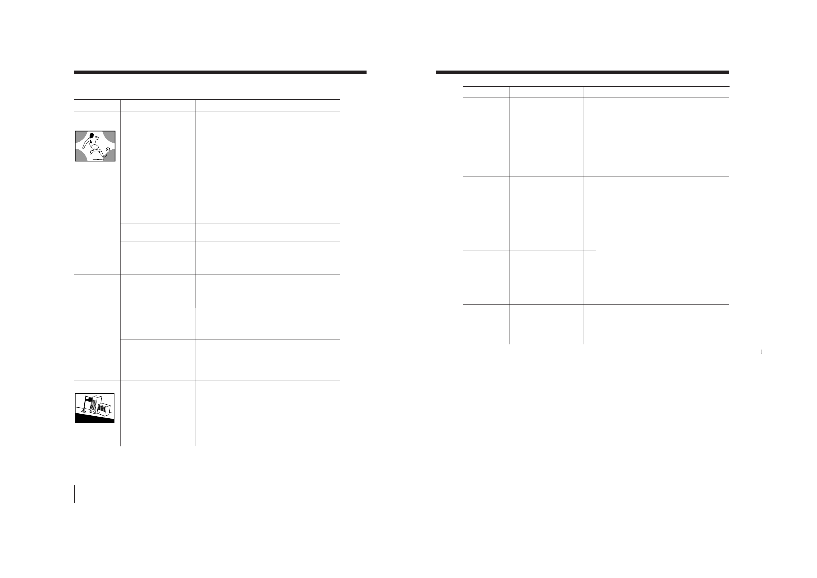
1. DIAGNOSTIC TEST INDICATORS
When an error occurs, the STANDBY/TIMER lamp will flash a number of times to indicate the possible cause of the
problem. If there is more than one error, the lamp will identify the first of the problem areas.
Result for all of the following diagnostic items are displayed on screen. No error has occured if the screen displays a
“0”.
Diagnostic
Item
Description
• Power does not
turn on
• +B overcurrent
(OCP)
• +B overvoltage
(OVP)
• Vertical
deflection failure
• White balance
failure (no
PICTURE)
• Horizontal
deflection failure
• Micro reset
No. of times
STANDBY/TIMER
lamp flashes
Does not light
2 times
3 times
4 times
5 times
6 times
—
Self-diagnostic
display/Diagnostic
result
—
002:000 or
002:001~255
003:000 or
003:001~255
004:000 or
004:001~255
005:000 or
005:001~255
006:000 or
006:001~225
101:00 or
101:001~225
Probable
Cause
Location
• Power cord is not plugged
in.
• Fuse is burned out F1601
(F1 Board)
• H.OUT Q6807 is shorted.
• H.IN Q6810 is shorted.
(D board)
• PH 6602 faulty.
• 10.5V is not supplied.
(D board)
• V.OUT IC6800 faulty
D6816 faulty
D6817 faulty
D6824 faulty
R6852 open
R6851 open (D board)
• G2 is improperly adjusted.
(Note 2)
• CRT problem.
• Video OUT IC9001, 9002,
9003 are faulty. (C board)
• IC8306 (A board) and
IC4301 (A board) are faulty.
• C6831 is open circuit.
(D board)
• CRT Discharge (C Board)
• Static discharge
• External noise
Detected
Symptoms
• Power does not come on.
• No power is supplied to the
TV.
• AC power supply is faulty.
• Power does not come on.
• Load on power line is
shorted.
• Power does not come on.
• Vertical deflection pulse is
stopped.
• Vertical size is too small.
• Vertical deflection stopped.
• No raster is generated.
• CRT cathode current
detection reference pulse
output is small.
• H pulse output is too high.
• Power is shut down shortly,
after this return back to
normal.
• Detect Micro latch up.
Note 1: Refer to screen (G2) Adjustment in section 6-5 of this manual.
– 4 –
Page 6
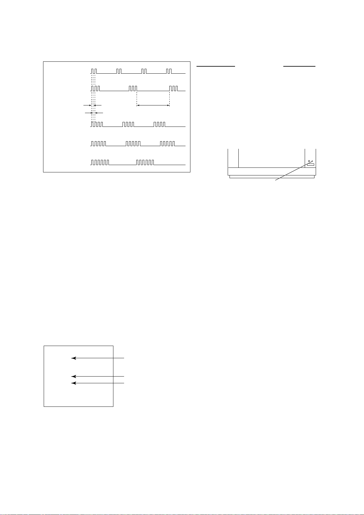
2. DISPLAY OF STANDBY/TIMER LIGHT FLASH COUNT
STANDBY/SLEEP lamp
2 times
3 times
Lamp ON 0.3 sec.
Lamp OFF 0.3 sec.
Lamp OFF 3 sec.
KV-EX29M61
RM-964
Diagnostic Item Flash Count*
+B overcurrent 2 times
+B overvoltage 3 times
V deflection stop 4 times
White balance failure 5 times
Horizontal Deflection Failure 6 times
4 times
5 times
6 times
* One flash count is not used for self-diagnostic.
3. STOPPING THE STANDBY/TIMER FLASH
Turn off the power switch on the TV main unit or unplug the power cord from the outlet to stop the STANDBY/TIMER lamp
from flashing.
4. SELF-DIAGNOSTIC SCREEN DISPLAY
For errors with symptoms such as “power sometimes shuts off ” or “screen sometimes goes out” that cannot be confirmed, it is possible to bring up past occurances of failure for confirmation on the screen:
[To Bring Up Screen Test]
In standby mode, press buttons on the remote commander sequentially in rapid succession as shown below:
[Screendisplay] / channel [5] / Sound volume [-] / Power ON
˘
Note that this differs from entering the service mode (mode volume [+]).
Self-Diagnosis screen display
SELF DIAGNOSTIC
002 : 000
003 : 000
004 : 000
005 : 001
006 : 002
101 : 000
Numeral "0" means that no fault has been detected.
Numeral "1" means a fault has been detected.
Numeral "2" means two faults have been detected.
– 5 –
Page 7
KV-EX29M61
RM-964
5. HANDLING OF SELF-DIAGNOSTIC SCREEN DISPLAY
Since the diagnostic results displayed on the screen are not automatically cleared, always check the self-diagnostic
screen during repairs. When you have completed the repairs, clear the result display to “0”.
Unless the result display is cleared to “0”, the self-diagnostic function will not be able to detect subsequent faults after
completion of the repairs.
[Clearing the result display]
To clear the result display to “0”, press buttons on the remote commander sequentially as shown below when the
diagnostic screen is being displayed.
Channel [8] / 0
[Quitting Self-diagnostic screen]
To quit the entire self-diagnostic screen, turn off the power switch on the remote commander or the main unit.
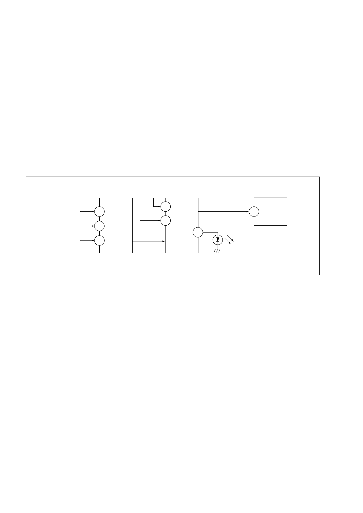
6. SELF-DIAGNOSTIC CIRCUIT
FROM
CRT (IK)
[H] IC6801
[V] D6806/D6801
IC4301
RGB JUNGLE
IKIN
20
XRAY
16
V PROT 1
CXA2100Q
OVP OCP
SDA
SYSTEM
3
6
IC001
LED 1
54
SDA
IC003
MEMORY
525
[+BovercurrentªOCPº] Occurs when an overcurrent on the +B(135) line is detected by
Q6610 and Q6609.
If Q6610 and Q6609 go to ON, the voltage to the pin3 of IC001 go to
UP. The unit will automatically turn off.
[+BovervoltageªOVPº] Occurs when an overvoltage on the +B(135) line is detected by
D6635, Q6611 and Q6612. If Q6611 and Q6612 go to ON, the
voltage to pin6 of IC001 go to UP. The unit will automatically turn off.
[Verticaldeflectionfailure] Occurs when an absence of the vertical deflection pulse is detected
by Q6811, Q6819, Q6820, Q6821 and D6801. Shut down the power
supply.
[Whitebalancefailure] If the RGB levels do not balance or become low level within 5
seconds. This error will be detected by IC4301.
TV will stay on, but there will be no picture.
[HighvoltageprotectorofHorizontalDeflection] Occurs when an overvoltage of horizontal pulse is detected by
D6809 and IC6801.
If the voltage of 7 pin of IC6801 goes to High, the voltage to pin20 of
IC4301 go to UP. The unit will automatically turn off.
– 6 –
Page 8
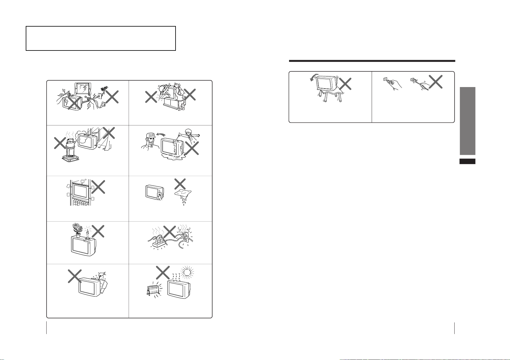
The operating instruction mentioned here are partial abstracts
2
WARNING
• Dangerously high voltages are present inside the TV.
• TV operating voltage: 110 – 240 V AC.
To prevent fire or shock hazard, do not expose
the TV to rain or moisture.
Do not operate the TV if any liquid or solid object
falls into it. Have it checked immediately by
qualified personnel only.
Do not open the cabinet and the rear cover of the
TV as high voltages and other hazards are
present inside the TV. Refer servicing and
disposal of the TV to qualified personnel.
Your TV is recommended for home use only.
Do not use the TV in any vehicle or where it may
be subject to excessive dust, heat, moisture or
vibrations.
Do not block the ventilation openings of the TV.
Do not install the TV in a confined space, such
as a bookcase or built-in cabinet.
For children’s safety, do not leave children
alone with the TV. Do not allow children to
climb onto it.
Do not plug in too many appliances to the same
power socket. Do not damage the power cord.
Clean the TV with a dry and soft cloth.
Do not use benzine, thinner, or any other chemicals
to clean the TV. Do not scratch the picture tube.
For your own safety, do not touch any part of the
TV, the power cord and the antenna cable during
lightning storms.
Do not place any objects on the TV.
3
Using Your New TV
GB
Install the TV on a stable TV stand and floor which
can support the TV set weight. Ensure that the TV
stand surface is flat and its area is larger than the
bottom area of the TV.
WARNING (continued)
Pull the power cord out by the plug. Do not pull
the power cord itself. Even if your TV is turned
off, it is still connected to the AC power source
(mains) as long as the power cord is plugged in.
Unplug the TV before moving it or if you are not
going to use it for several days.
from the Operating Instruction Manual. The page numbers of
the Operating Instruction Manual remain as in the manual.
SECTION 1
GENERAL
– 7 –
KV-EX29M61
RM-964
Page 9
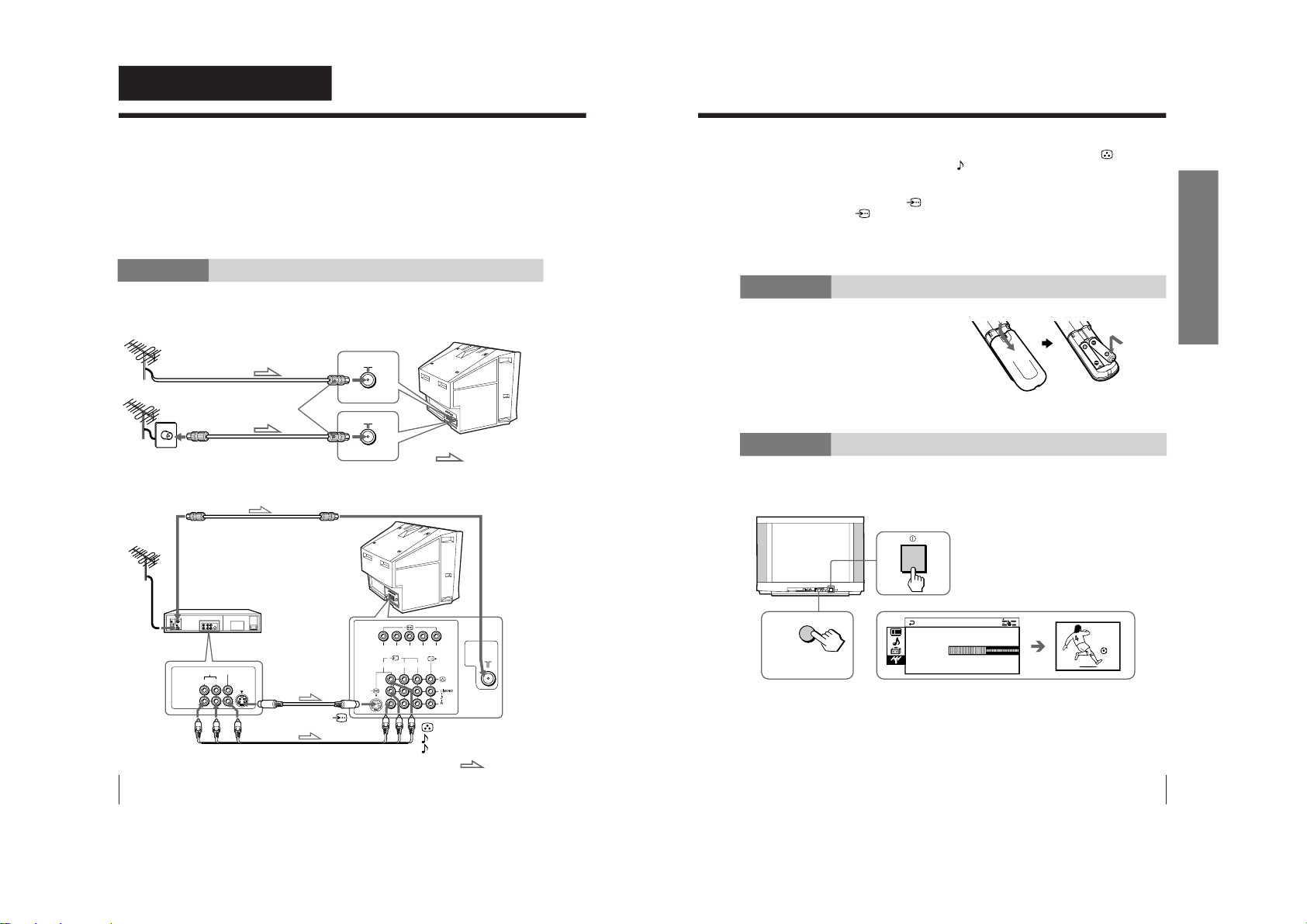
4
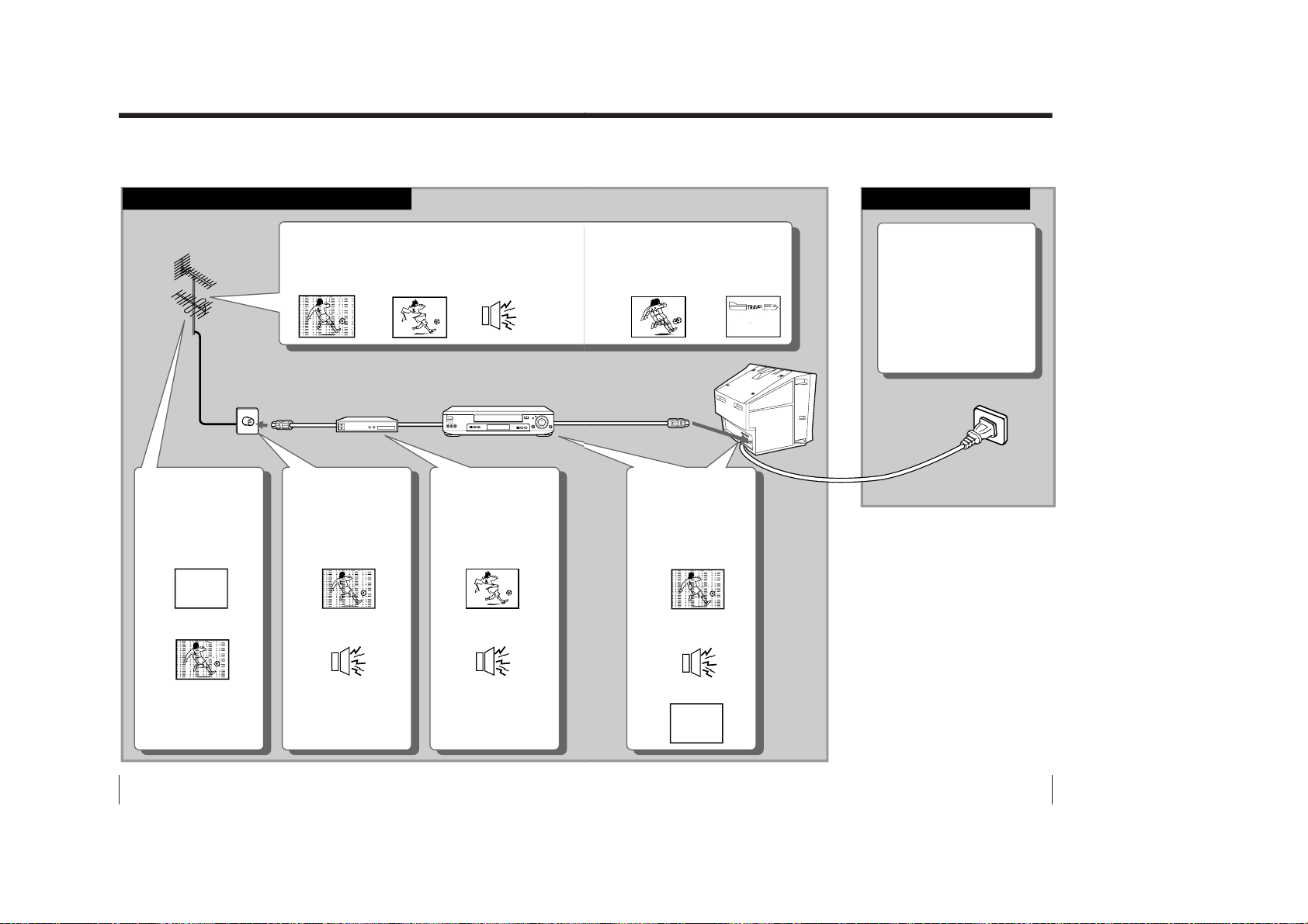
Using Your New TV
Using Your New TV
: Signal flow
IEC connector
(not supplied)
or
Antenna cable (not supplied)
Antenna cable (not supplied)
Rear of TV
To video and
audio outputs
To S video
output
Audio/Video cable
(not supplied)
: Signal flow
To
(S video input)
VCR
Antenna cable (not supplied)
To antenna
output
To ˘ (antenna)
123
R
L
Y
C
B
C
R
VIDEO
VIDEO IN
VIDEO OUT
AUDIO
R L
Rear of TV
(yellow)
-L (MONO) (white)
-R (red)
To t 1, 2, or 3
(video input)
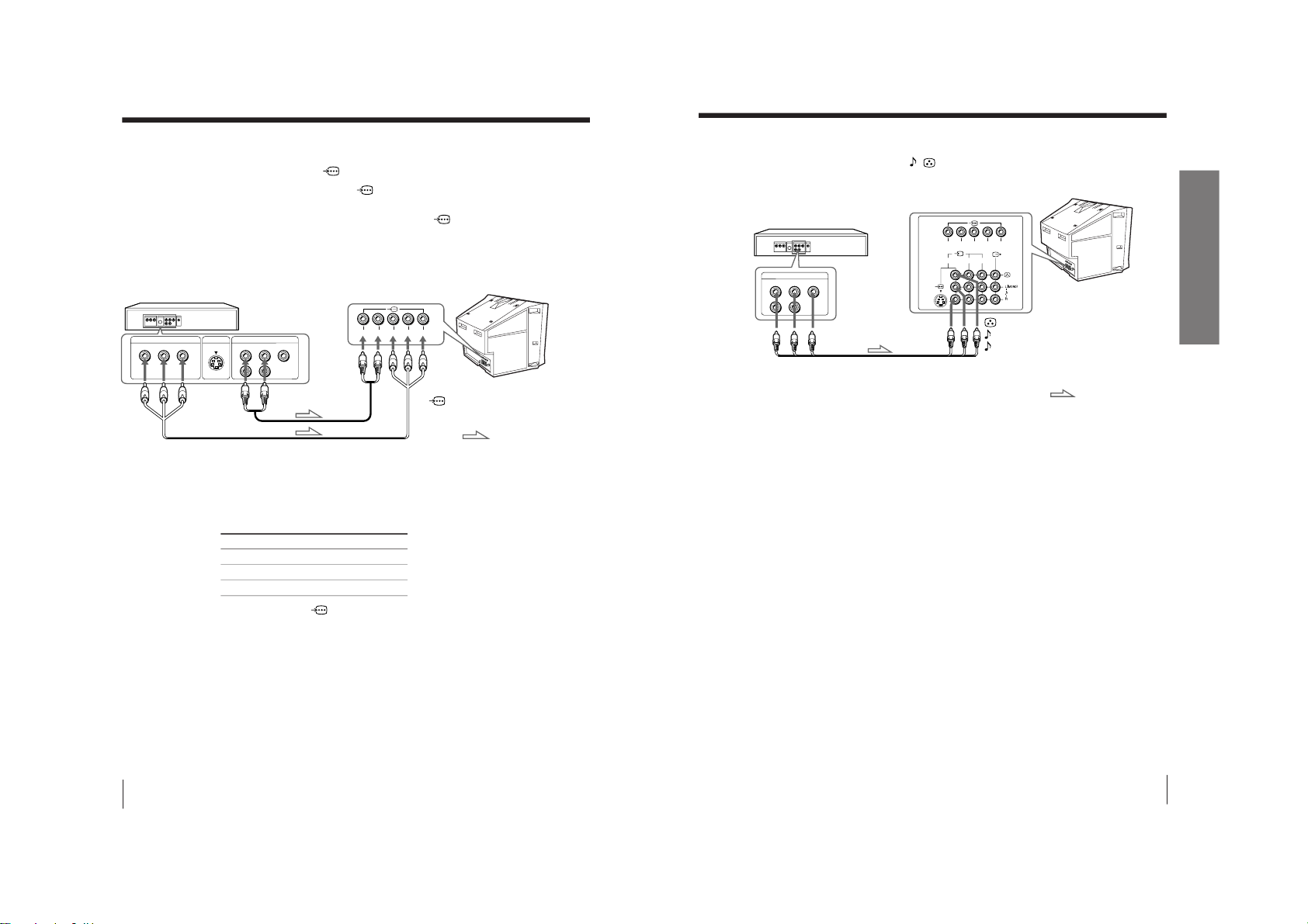
Getting Started
Step 1
Connect the antenna
If you wish to connect a VCR, see the Connecting a VCR diagram below.
Connecting a VCR
To watch the video input, press t (see page 12).
CAUTION
• Do not connect the power cord until you have completed making all other
connections; otherwise a minimum leakage current might flow through
the antenna and other terminals to ground.
• To avoid battery leakage and damage to the remote, remove the batteries
from the remote if you are not going to use it for several days. If any
liquid that leaks from the batteries touches you, immediately wash it
away with water.
S video cable
(not supplied)
5
Using Your New TV
Using Your New TV
2
L(M
ONO)
R
4
PROGR
MEN
U
AUTO
PROGR
ENTER
SELECT
AUTO
PROGR
1
b
M
PR : 0 1
AUTO PROGRA
VHF LOW
TV SYS : AUTO
1
Front panel
Notes
• If you connect a monaural VCR, connect the yellow plug to
(the yellow
jack) and the black plug to
-L (MONO) (the white jack).
• If you connect a VCR to the 8 (antenna) terminal, preset the signal
output from the VCR to the program number 0 on the TV.
• When both the
(S video input) and t 1 (video input) are connected,
the
(S video input) is automatically selected. To view the video input
to t 1 (video input), disconnect the S video cable.
• When no signal is input from the connected video equipment, the TV
screen becomes blue.
Step 2
Insert the batteries into
the remote
Note
• Do not use old batteries or different types of batteries together.
Step 3
Preset the channels automatically
Tips
• To stop the automatic channel presetting, press MENU.
• If your TV has preset an unwanted channel or cannot preset a particular
channel, then preset your TV manually (see page 33).
KV-EX29M61
RM-964
– 8 –
Page 10
6
Using Your New TV
Connecting the 3D WOOFER
(Not used for this model)
You can enjoy high quality sound by connecting the 3D WOOFER.
Bottom of 3D WOOFER
1
Place the foot at the front of the 3D WOOFER into the footholds on the top
of your TV.
2
Place the foot at the rear of the 3D WOOFER into the footholds at the rear
of your TV.
3
Connect the wires to the 3D WOOFER (4Ω) terminals at the rear of your TV.
The red wire should be connected to the ‘ red terminal and the black wire
to the ’ black terminal.
Notes
• Connect only the supplied 3D WOOFER; otherwise your TV may
malfunction.
• Unplug your TV from the wall outlet when connecting the 3D WOOFER.
• To prevent a malfunction caused by a short circuit of the terminals, make
sure that none of the 3D WOOFER wire strands stick out, making contact
with it’s neighbouring 3D WOOFER terminal.
Rear of TV
3D WOOFER
1
2
3
Black wire
Red wire
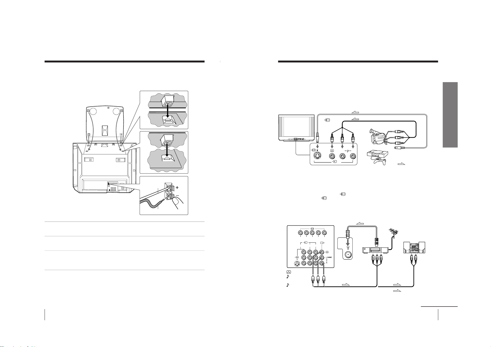
7
Using Your New TV
Using Your New TV
Connecting optional components
You can connect optional audio/video components, such as a VCR, multi disc player,
camcorder, video game, or stereo system. To watch the picture from the connected
equipment, see page 12.
Connecting a camcorder/video game equipment
using the t (video input) jacks
Notes
• When connecting video game equipment, display the
“PICTURE” menu
and select “ON” for “GAME MODE” to adjust the pictur
e setting that is
suitable for video games (see page 26).
• You can also connect video equipment to the t 1, 2, or 3 (video input)
jacks at the rear of your TV.
• When both the
(S video input) and t 4 (video input) are connected,
the
(S video input) is automatically selected. To view the video input
to t 4 (video input), disconnect the S video cable.
Connecting audio/video equipment using the T
(monitor output) jacks
Note
• If you select “DVD” on your TV scr
een, no signal will be output at the
T (monitor output) jacks (see page 12).
: Signal flow
or
Video game
equipment
(yellow)
-L (MONO)
(white)
-R (red)
Rear of TV
To
antenna
output
To video and
audio inputs
Audio system
To
audio
inputs
VCR
: Signal flow
To T
(monitor
output)
Antenna cable (not supplied)
Audio cable
(not supplied)
Audio/Video cable (not supplied)
L(MONO)
R
4
PROGRMENU
AUTO
PROGR
ENTERSELECT
L(MONO) R
4
123
R
L
Y
C
B
C
R
continued
Camcorder
To video and
audio outputs
To
(S video
input)
To
…
4
(video input)
or
Audio/Video cable (not supplied)
S video cable (not supplied)
Front of TV
To S video output
– 9 –
KV-EX29M61
RM-964
Page 11
8
Using Your New TV
Connect To (on the DVD player)
Y (green) Y
C
B
(blue) C
b
, B-Y or P
B
C
R
(red) C
r
, R-Y or P
R
Connecting a DVD player to
(component video input)
1 Using an audio cable, connect R and L under
(component video input) on your
TV to the LINE OUT, AUDIO R and L output connectors on your DVD player.
2 Using a component video cable, connect Y, C
B
, and C
R
under
(component video
input) on your TV to the COMPONENT VIDEO OUT Y, C
B
, and C
R
output
connectors on your DVD player.
3 Press t on the remote or the TV until
“DVD” appears on the scr
een.
To component
video output
Component video cable
(not supplied)
DVD player
To
L (white)
R (red)
To audio
output
Audio cable
(not supplied)
: Signal flow
To
(component video input)
VIDEO
R-AUDIO-L
LINE OUT
Y
COMPONENT VIDEO OUT
S VIDEO OUT
CB C
R
R
L
Y
C
B
C
R
Notes
• Some DVD player terminals may be labeled differently:
• When connecting to
(component video input) on your TV, you must
connect Y, C
B
, and C
R
to receive the video signals, and connect L and R to
receive analog audio signals.
Connecting optional components (continued)
Rear of TV
9
Using Your New TV
Using Your New TV
123
R
L
Y
C
B
C
R
VIDEO
R-AUDIO-L
LINE OUT
Connecting a DVD player to t (video input)
Connect t 1, 2, or 3 (video input)
/
(audio/video) connectors on your TV to LINE
OUT on your DVD player.
DVD player
(yellow)
-L (MONO) (white)
-R (red)
To t 1, 2, or 3
(video input)
: Signal flow
Audio/Video cable (not supplied)
Notes
• Since the high quality pictures on a DVD disc contain a lot of information,
picture noise may appear. In this case, adjust the sharpness (
“SHARP”)
under “PERSONAL ADJUST” in the “PICTURE MODE
” menu (see
page 27).
• Connect your DVD player directly to your TV. Connecting the DVD
player through other video equipment will cause unwanted picture noise.
Rear of TV
To video and
audio outputs
– 10 –
KV-EX29M61
RM-964
Page 12
10
Using Your New TV
A
B
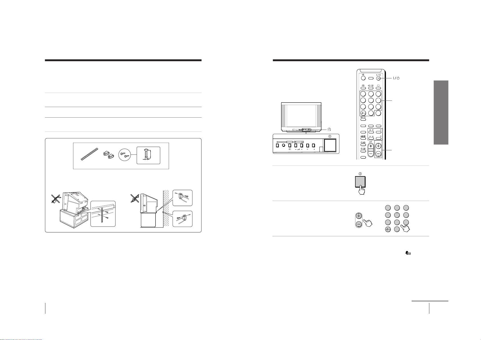
Securing the TV
To prevent the TV from falling, secure the TV using one of the following methods:
A
With the supplied screws, attach the stabilizer band to the TV stand and to
the rear of the TV using the provided hole.
OR
B
Put the cord or chain through the clamps to secure the TV against a wall or
pillar.
Note
• Use only the supplied screws. Use of other screws may damage the TV.
OR
3.8 mm
20
mm
11
Using Your New TV
Using Your New TV
1
Press ! to turn on the TV.
When the TV is in standby
mode (the 1 indicator on
the TV is lit red), press ?/1
on the remote or
PROGR +/– on the TV.
2
Press PROGR +/– or the
number buttons to select
the TV channel.
For double digit numbers, press
-, then the number (e.g., for 25,
press -, then 2 and 5).
Note
• When you turn on the TV, either the program number or video mode is
displayed for approximately 40 seconds. The ECO MODE (
) icon will
also appear if “ECO MODE “ in the “SETUP” menu is set “ON” (see
page 30).
To select a TV program quickly
(1) Press and hold PROGR +/
–.
(2) Release PROGR +/
– when the desir
ed program number appears.
Note
• When you select a TV program quickly, the picture may be disrupted.
This does not indicate a malfunction.
Number buttons
PROGR +/–
Watching the TV
This section explains various functions
and operations available while watching
the TV. Most operations can be done
using the remote.
or
1
4
7
2
5
8
0
3
6
9
FAVORITE
SOUND
MODE
RESET
PIC MODE
PROGR
DRC-MF
ENTER
MENU
SURROUND
JUMP
PROGRMENU
AUTO
PROGR
ENTER SELECT
L(MONO) R
4
PROGRMENU
AUTO
PROGR
ENTER SELECT
123
456
78
0
9
PROGR
1 indicator
continued
– 11 –
KV-EX29M61
RM-964
Page 13
13
Using Your New TV
Using Your New TV
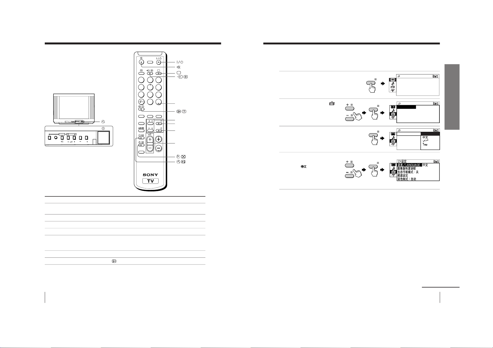
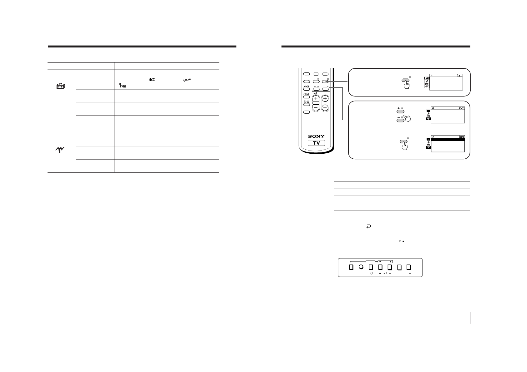
Changing the menu language
You can change the menu language as well as the on-screen language. For details on
how to use the menu, see Introducing the menu system on page 23.
1
Press MENU.
2
Press + or – to select
,
then press ENTER.
3
Make sure “LANGUAGE” is
selected then press ENTER.
4
Press + or – to select the
desired language
(e.g.,”
“), then
press ENTER.
The selected menu
language appears.
To return to the normal screen
Press MENU.
P I CTURE MO C
PICTURE
GAME MODE ++++++++++++
WI D E MODE : OFF
:
OFF
DE : DYNAM I
DRC - MF : DRC 1 2 5 0
E
COLOR SYS : AUTO
SETUP
PROGRAM SETUP
PIC ROTAT I ON
NGL I SH
ECO MODE :OF F
L ANGU AGE :
L ANGU AGE :
COLOR SYS :
T
SETUP
PROGRAM SE
F
PIC ROTAT I O
ENGL I SH
ECO MODE :O
A
continued
MENU
ENTER
ENTER
ENTER
12
Using Your New TV
Watching the TV (continued)
To
Turn off temporarily
Turn off completely
Adjust the volume
Mute the sound
Watch the video input
(VCR, camcorder, etc.)
Jump back to the previous channel
Display the on-screen information*
Press
?/ 1.
The 1 indicator on the TV lights up red.
! on the TV.
2+/–.
%.
t (or t on the TV) to select
“VIDEO 1”,
“VIDEO 2”, “VIDEO 3”, “VIDEO 4”or “DVD”.
To return to the TV screen, press a (or t on the TV).
JUMP.
.
Additional tasks
JUMP
2 +/–
MENU
1
4
7
2
5
8
0
3
6
9
FAVORITE
SOUND
MODE
RESET
PIC MODE
PROGR
DRC-MF
ENTER
MENU
SURROUND
JUMP
* Some picture/sound settings, and either the program number or video
mode are displayed. The on-screen display for the picture/sound settings
disappears after about 3 seconds.
PROGRMENU
AUTO
PROGR
ENTER SELECT
L(MONO) R
4
PROGRMENU
AUTO
PROGR
ENTER SELECT
ENTER
+/–
1 indicator
KV-EX29M61
RM-964
– 12 –
Page 14
14
Using Your New TV
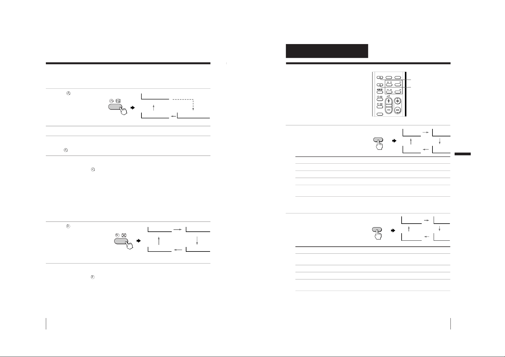
Setting the Wake Up timer
1
Press
until the desired
period of time appears.
The Wake Up timer starts
immediately after you
have set it.
2
Select the TV channel or video mode you want to wake up to.
3
Press 1/1, or set the Sleep timer if you want the TV to turn off
automatically.
The
indicator on the TV lights up orange.
To cancel the Wake Up timer
Press
until “WAKE UP TIMER: OFF” appears, or turn off the TV’s
main power.
Note
• If no buttons or controls are pressed for more than two hours after the TV
is turned on using the Wake Up timer, the TV automatically goes into
standby mode. To resume watching the TV, press any button or control on
the TV or the remote.
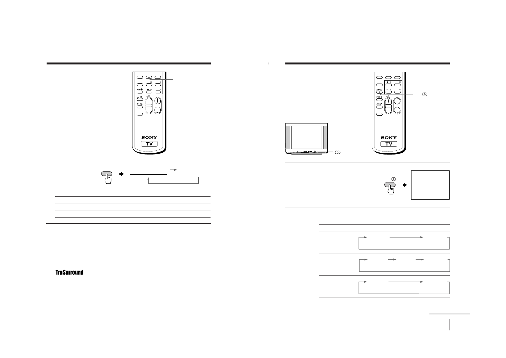
Setting the Sleep timer
Press
until the desired
period of time appears.
The Sleep timer starts
immediately after you
have set it.
To cancel the Sleep timer
Press
until “SLEEP TIMER: OFF” appears, or turn the TV off.
Watching the TV (continued)
WAKE UP TIMER:10M
WAKE UP TIMER:OFF
WAKE UP TIMER:12H00M
After 10 minutes
No Wake Up Timer After 12 hours
SLEEP TIMER:30M
SLEEP TIMER:60M
SLEEP TIMER:OFF
SLEEP TIMER:90M
After 30 minutes
No Sleep Timer
After 60 minutes
After 90 minutes
15
Advanced Operations
Advanced Operations
Advanced Operations
Selecting the picture mode
Press PIC MODE
repeatedly until the
desired picture mode is
selected.
Select
“DYNAMIC”
“STANDARD”
“HI-FINE”
“PERSONAL”
To
receive high contrast pictures.
receive normal pictures.
receive higher resolution pictures with mild contrast.
receive the last adjusted picture setting from the “ADJUST” option in the
“PICTURE” menu (see page 27).
Selecting the sound mode
Press SOUND MODE
repeatedly until the
desired sound mode is
selected.
Select
“DYNAMIC”
“DRAMA”
“SOFT”
“PERSONAL”
To
listen to dynamic and clear sound that emphasizes both the low and high
tones.
listen to sound that emphasizes voice and high tones.
receive soft sound.
receive the last adjusted sound setting from the “ADJUST” option in the
“SOUND” menu (see page 29).
Tip
• You can also set the picture and sound modes using the menu (see
Changing the “PICTURE” setting on page 26 and Changing the
“SOUND” setting on page 28 ).
Selecting the picture
and sound modes
You can select picture and sound modes
and adjust the setting to your preference
in the “PERSONAL” option.
FAVORITE
SOUND
MODE
RESET
PIC MODE
PROGR
ENTER
MENU
SURROUND
PIC MODE
PERSONAL
DYNAMIC
HI-FINE
STANDARD
PIC MODE
SOUND MODE
≥
DYNAMIC
≥
PERSONAL
≥
SOFT
≥
DRAMA
SOUND
MODE
– 13 –
KV-EX29M61
RM-964
Page 15
16
Advanced Operations
Viewing higher
quality pictures
— “DRC-MF”
The Digital Reality Creation-Multi
Function (DRC-MF) feature allows you
to enjoy higher quality pictures on your
TV. You can select “DRC1250” to watch
super real (higher resolution) pictures,
or “DRC PROGRESSIVE
” to r
educe any
jittering on the screen if necessary.
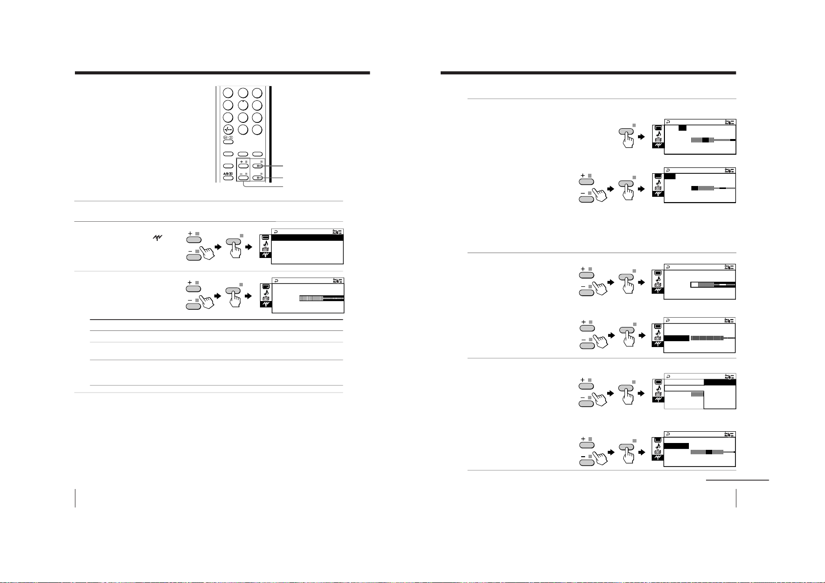
Press DRC-MF repeatedly
until you receive the
desired picture quality.
Tips
• You can also select the DRC-MF option using the menu (see Changing the
“PICTURE” setting on page 26).
• When the broadcast signal is weak, you may see some dots or noise on the
TV screen. To reduce this interference, display the
“PICTURE” menu and
select “ADJUST” in “PICTURE MODE
”, then adjust “SHARP” to r
educe
the sharpness (see page 27).
Note
• The DRC-MF mode is not selectable when the
“GAME MODE” is turned
“ON”.
The DRC-MF logo (
) and “DRC-MF” ar
e trademarks of
Sony Corporation.
Select
“DRC1250”
“DRC PROGRESSIVE
”
To
select higher resolution pictures.
reduce jitter of any small areas or scanning lines (e.g., letters
or the edge of objects) on the screen.
1
4
7
2
5
8
0
3
6
9
FAVORITE
SOUND
MODE
PIC MODE
DRC-MF
ENTER
MENU
SURROUND
JUMP
DRC-MF
DRC-MF: DRC1250 DRC-MF: DRC PROGRESSIVE
DRC-MF
17
Advanced Operations
Advanced Operations
FAVORITE
1
4
7
2
5
8
0
3
6
9
FAVORITE
SOUND
MODE
RESET
PIC MODE
PROGR
DRC-MF
ENTER
MENU
SURROUND
JUMP
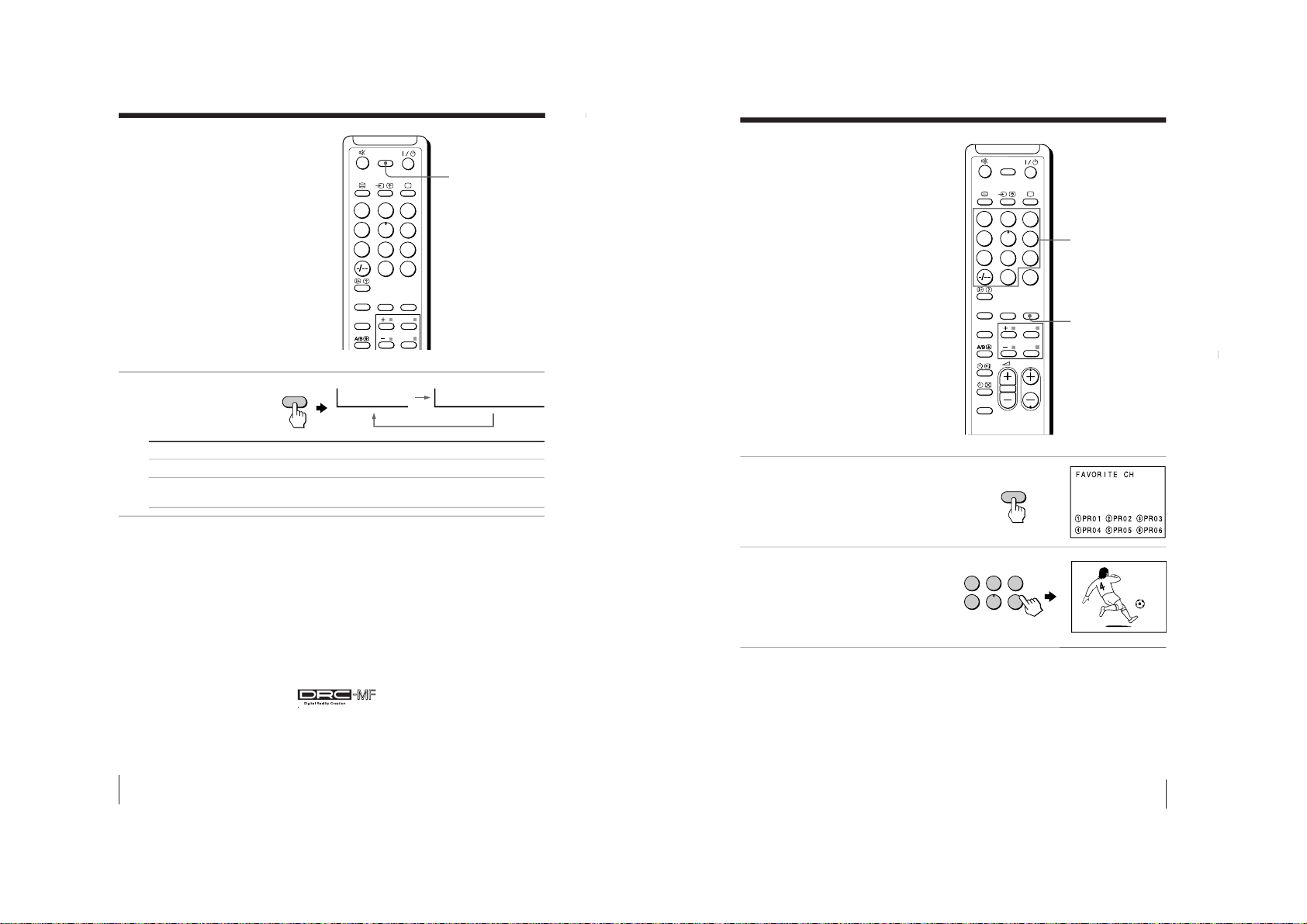
1
Press FAVORITE.
2
Press the number button
from 1 to 6 to select the
desired channel.
Tip
• To program your favorite channels, see Adjusting each channel settings
(PROGRAM SETUP) on page 31.
Viewing your
favorite channels
You can display and select six of your
favorite channels directly from your TV
screen.
Number buttons
1
2
3
4
5
6
1
b
FAVORITE
– 14 –
KV-EX29M61
RM-964
Page 16
18
Advanced Operations
Press SURROUND
repeatedly until you
receive the desired
surround sound.
Select To
“TruSurround” listen to the surround sound that spreads out to the rear of a room.
“OFF” turn off the surround sound.
Tip
• You can also select the surround option using the menu (see Changing the
“SOUND” setting on page 28).
The surround of your TV is categorized as TruSurround.
TM
is a trademark of SRS Labs, Inc. SRS and the SRS symbol are
registered trademarks of SRS Labs, Inc. in the United States and selected foreign
countries. SRS and TruSurround are incorporated under license from SRS Labs,
Inc. and are protected under United States Patent Nos. 4,748,669 and 4,841,572
with numerous additional issued and pending foreign patents.
Listening with
surround sound
The surround feature enables you to
enjoy the sound effects of a concert hall
or movie theater.
FAVORITE
SOUND
MODE
RESET
PIC MODE
PROGR
ENTER
MENU
SURROUND
SURROUND
SURROUND: OFF
SURROUND: TruSurround
SURROUND
19
Advanced Operations
Enjoying stereo or
bilingual
programs
You can enjoy stereo sound or bilingual
programs of NICAM and A2 stereo
systems.
Press A/B repeatedly until you
receive the sound you want.
The on-screen display changes to
show the selected sound.
The  indicator on the TV lights
up red when receiving any stereo
or bilingual program.
When receiving a NICAM program
A/B
Broadcasting On-screen display (Selected sound)
NICAM stereo
NICAM bilingual
NICAM monaural
FAVORITE
SOUND
MODE
RESET
PIC MODE
PROGR
ENTER
MENU
SURROUND
NICAM
MONO
(Stereo sound)
(Regular sound)
NICAM
MAIN
MONO
(Main sound)
(Regular sound)
NICAM
SUB
(Sub sound)
NICAM
MAIN
MONO
(Main sound)
(Regular sound)
NICAM
A/B
continued
L(MONO) R
4
PROGRMENU
AUTO
PROGR
ENTER SELECT
indicator
– 15 –
KV-EX29M61
RM-964
Page 17
20
Advanced Operations
When receiving an A2 program
Receiving area for NICAM and A2 programs
Notes
• If the signal is very weak, the sound becomes monaural automatically.
• If the stereo sound is noisy when receiving a NICAM program, select
“MONO”. The sound becomes monaural, but the noise is reduced.
If the sound is distorted when receiving a monaural program
through the 8 (antenna) terminal
Press A/B repeatedly until
“MONO” appears on the scr
een.
To cancel the monaural sound setting, press A/B again until
“AUTO” appears on the screen.
Notes
• The “MONO” or “AUT
O” setting is memorized for each program
position.
• You cannot receive a stereo broadcast signal when the TV is in the
“MONO” setting. Normally, set the TV to “AUTO”.
Broadcasting On-screen display (Selected sound)
A2 stereo
A2 bilingual
MAIN
SUB
(Main sound)
(Sub sound)
MONO
AUTO
System
NICAM
A2
Receiving area
Hong Kong, Singapore, New Zealand, Malaysia,
Thailand, etc.
Australia, Malaysia, Thailand, etc.
Enjoying stereo or bilingual programs (continued)
STEREO
MONO
(Stereo sound)
(Regular sound)
21
Advanced Operations
Viewing Teletext
Some TV stations broadcast an
information service called Teletext
which allows you to receive various
information, such as stock market
reports and news.
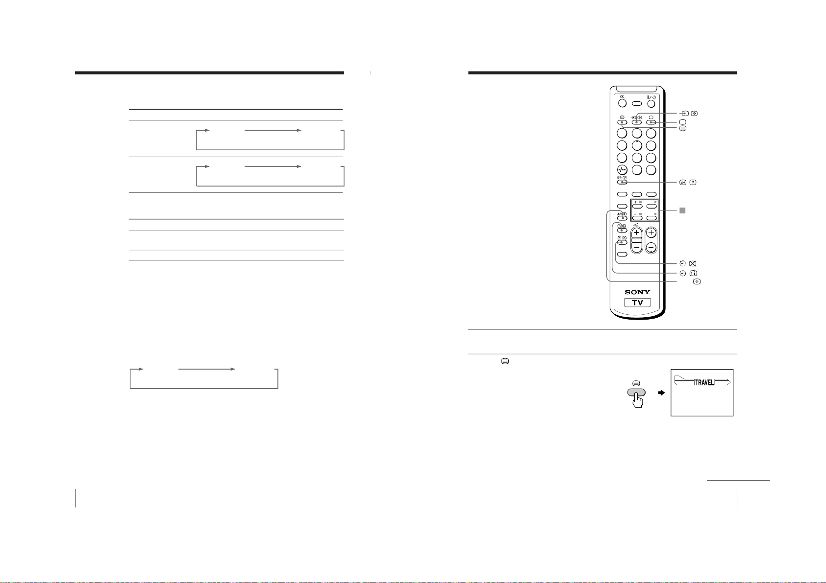
Displaying Teletext
1
Select a TV channel that carries the Teletext broadcast you want to watch.
2
Press
to display the
text.
A Teletext page (normally
the index page) is
displayed. If there is no
Teletext broadcast, “100” is
displayed at the top left
corner of the screen.
To turn off Teletext
Press a.
continued
(red, green,
yellow,blue)
1
4
7
2
5
8
0
3
6
9
FAVORITE
SOUND
MODE
RESET
PIC MODE
PROGR
DRC-MF
ENTER
MENU
SURROUND
JUMP
A/B
P166 SECTEXT 166 FR1 MAR 03:59:09
From Singapore
To PAR IS
To OSAKA
To ROMA
To SYDNEY
Day Dep/Arr Flight Alrcraft
1.6 220/0588 SQ28 747
2 2130/1225 PA115 L15
3 2115/1330 SQ26 747
2.7 2130/0745 SQ24
747
4 2300/0915 AZ487 747
2.5 1000/1715 SQ6 747
4.6 0930/2015 CX522 L10
1 2210/0610 SQ21A 747
2 2100/0835 SQ21A 747
– 16 –
KV-EX29M61
RM-964
Page 18
22
Advanced Operations
Additional Teletext tasks
To
display a Teletext page on the TV
picture
check the contents of a Teletext service
select a Teletext page
hold (pause) a Teletext display
reveal concealed information
(e.g., an answer to a quiz)
enlarge the Teletext display
stand by for a Teletext page while
watching a TV program
* You can also select a Teletext page that appears in the colored columns at
the bottom of the screen using the corresponding color-coded buttons on
the remote.
Using FASTEXT
This feature allows you to quickly access a Teletext page that uses
FASTEXT. When a FASTEXT program is broadcast, colored menus
appear at the bottom of the screen. The color of each menu
corresponds to the color-coded buttons on the remote (red
,
green , yellow , and blue ).
To access a FASTEXT menu
Press the color-coded button on the remote corresponding to the
menu you want. The menu page appears on the screen after a few
seconds.
Do this
Press
.
Each time you press
, the screen changes as
follows: Teletext n Teletext and TV n TV.
Press
.
An overview of the Teletext contents, including
page numbers, appears on the screen.
Press the number buttons to enter the three-digit
page number of the desired Teletext page.* If you
make a mistake, reenter the correct page number. To
access the next or previous page, press PROGR +/–.
Press
to display the symbol
“
j” at the top left
corner of the screen. To resume normal Teletext
viewing, press
or
.
Press
.
To conceal the information, press the button again.
Press
.
Each time you press
, the Teletext display
changes as follows: Enlarge upper half n Enlarge
lower half n Normal size.
1 Enter the Teletext page number that you want to
refer to, then press
.
2 When the page number is displayed, press
to
show the text.
Viewing teletext (continued)
23
Adjusting Your Setup (MENU)
Adjusting Your Setup (MENU)
Level 1
“PICTURE”
“SOUND”
Adjusting Your Setup (MENU)
Level 2
“DRC-MF”
“PICTURE MODE
”
“ADJUST”
“WIDE MODE”
“GAME MODE”
“SOUND MODE
”
“ADJUST”
“SURROUND”
“INTELLIGENT
VOL”
Level 3/Function
Select the “DRC-MF” mode:
“DRC1250” t “PROGRESSIVE
”
Select the picture mode:
“DYNAMIC” t “STANDARD” t “HI-FINE” t
“PERSONAL” t “ADJUST”
Adjust the “PERSONAL” option:
“PICTURE” t “COLOR” t “BRIGHT” t “HUE” t
“SHARP”
Change the picture size.
Adjust the picture settings for video games.
Select the sound mode:
“DYNAMIC” t “DRAMA” t “SOFT” t
“PERSONAL” t “ADJUST”
Adjust the “PERSONAL” option:
“BASS” t “TREBLE” t “BALANCE” t “BBE”*
Select the “SURROUND” mode:
“TruSurround” t “OFF”
Adjust volume automatically.
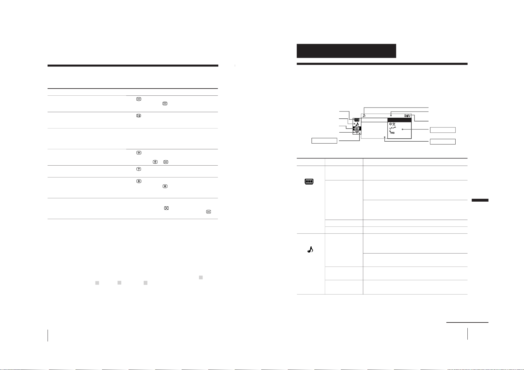
Introducing the menu system
The MENU button lets you open a menu and change the settings of your TV. The
following is an overview of the menu system.
continued
Return icon
CH PRESET icon
SETUP icon
SOUND icon
Name of the current
menu
PICTURE icon
Menu level 3
Menu level 2
Guide mark icon
Menu level 1
LANGUAGE :
COLOR SYS :
SETUP
PROGRAM SE
PIC ROTAT I
ENGL I SH
OMEC ODE : O
– 17 –
KV-EX29M61
RM-964
Page 19
24
Adjusting Your Setup (MENU)
Introducing the menu system (continued)
Level 1
“SETUP”
“CH PRESET”
Level 2
“LANGUAGE”
“PIC ROTATION”
“ECO MODE”
“PROGRAM
SETUP”
“COLOR SYS”
“AUTO
PROGRAM”
“MANUAL
PROGRAM”
“TV SYS”
Level 3/Function
Change the menu language:
“ENGLISH” t “
”(Chinese) t “
”(Arabic) t
“
” (Thai)
Adjust the picture position.
Reduce power consumption of your TV.
Adjust each channel settings.
Select the color system:
“AUTO” t“ PAL ” t “SECAM” t “NTSC3.58” t
“NTSC4.43”
Preset channels automatically.
Preset channels manually.
Select the TV system:
“B/G” t “I” t “D/K” t “M”
* The BBE is manufactured by Sony Corporation under license from BBE
Sound, Inc. It is covered by U.S. Patent No. 4,638,258 and No. 4,482,866.
The word “BBE” and the BBE symbol are the trademarks of BBE Sound, Inc.
25
Adjusting Your Setup (MENU)
Adjusting Your Setup (MENU)
How to use the menu
Press + or – to select
the desired item.
Press ENTER to
confirm your
selection and go to
the next level.
Press MENU to display
the menu.
Other menu operations
Tips
• If you want to exit from Menu level 2 to Menu level 1, press + or – until
the return icon (
) is highlighted, then press ENTER.
• Some of the menu items can be operated directly using the remote
buttons.
• The MENU, ENTER, and SELECT
/
buttons on the TV can also be used
for the operations above.
Note
• If more than 60 seconds elapse between entries, the menu screen
automatically disappears.
FAVORITE
SOUND
MODE
RESET
PIC MODE
PROGR
ENTER
MENU
SURROUND
b
PICTURE MO C
PICTURE
GAME MODENN T PIC:OFF
WIDE MODE: OFF
:OFF
DE : DYNAM I
DRC - MF :DRC 12 5 0
MENU
b
AUTO PROGR
CH PRES ET
TV SYS:B/G
MA NU A L P RO GR A M
AM
b
AUTO PROGR
CH PRE SET
TV SYS : B / G
MANUA L PROGRAM
AM
ENTER
PROGRMENU
AUTO
PROGR
ENTER SELECT
Front of TV
To
Adjust the setting value
Return to the previous menu level
Cancel the menu
Press
+ or –.
ENTER.
MENU.
– 18 –
KV-EX29M61
RM-964
Page 20
26
Adjusting Your Setup (MENU)
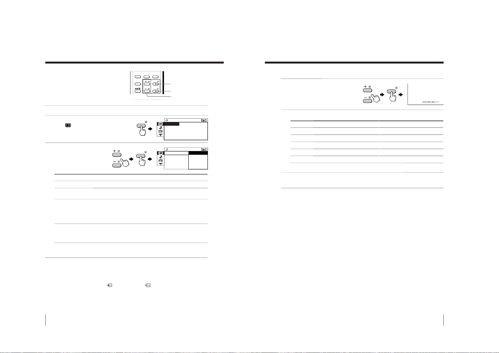
Changing the
“PICTURE” setting
The “PICTURE” menu allows you to adjust
the picture settings.
1
Press MENU.
2
Make sure the
“PICTURE”
icon (
) is selected,
then press ENTER.
3
Press + or – to select
the desired item
(e.g., “DRC-MF”),
then press ENTER.
* When the “PERSONAL” mode is selected, you can r
eceive the last
adjusted picture settings from the “ADJUST” option (see page 27).
Notes
• For details on the options under
“DRC-MF
” and “PICTURE MODE”, see
pages 16 and 15 respectively.
•“GAME MODE” is available only when receiving signals through the t
(video input),
(S video input), or
(component video input) jacks at
the front and rear of your TV.
To return to the normal screen
Press MENU.
MENU
FAVORITE
SOUND
MODE
PIC MODE
PROGR
ENTER
MENU
SURROUND
DRC - MF : DRC
C
GAME MODE : OF F
PICTURE
WI D E MODE : OFF
PI CTURE MODE : DYNAM I
1250
DRC - MF :
GAME MODE : O
PICTURE
WI DE MOD E : O
PI CTURE MOD
PROGRESSIVE
DRC1 25 0
ENTER
+/–
Select
“DRC-MF”
“PICTURE MODE”
“WIDE MODE”
“GAME MODE”
ENTER
ENTER
To
choose either “DRC1250” or “PROGRESSIVE
”.
choose either “DYNAMIC”, “ST
ANDARD”, “HI-FINE”,
“PERSONAL”*, or “ADJUST”.
change the picture size when receiving wide-mode (16:9) picture
signal.
Press + or – to select “ON”, then press ENTER.
To cancel, select “OFF”, then pr
ess ENTER.
adjust the picture setting that is suitable to view video games.
Press + or – to select “ON”, then press ENTER.
To cancel, select
“OFF”, then pr
ess ENTER.
27
Adjusting Your Setup (MENU)
Adjusting Your Setup (MENU)
Adjusting the
“ADJUST” items under
“PICTURE MODE
”
1
Press + or – to select
the desired item
(e.g.,“COLOR”),
then press ENTER.
2
Adjust the value according to the following table, then press ENTER.
* You can adjust “HUE” for the NTSC color system only
.
3
Repeat the above steps to adjust other items.
The adjusted settings will be received when you select
“PERSONAL”.
Tip
• For details on the menu system and how to use the menu, refer to
Introducing the menu system on page 23.
For
“PICTURE”
“COLOR”
“BRIGHT”
“HUE”*
“SHARP”
COLOR
08
Press + to
increase picture contrast
increase color intensity
brighten the picture
increase green picture tones
sharpen the picture
Press – to
decrease picture contrast
decrease color intensity
darken the picture
increase red picture tones
soften the picture
ENTER
– 19 –
KV-EX29M61
RM-964
Page 21
KV-EX29M61
28
Adjusting Your Setup (MENU)
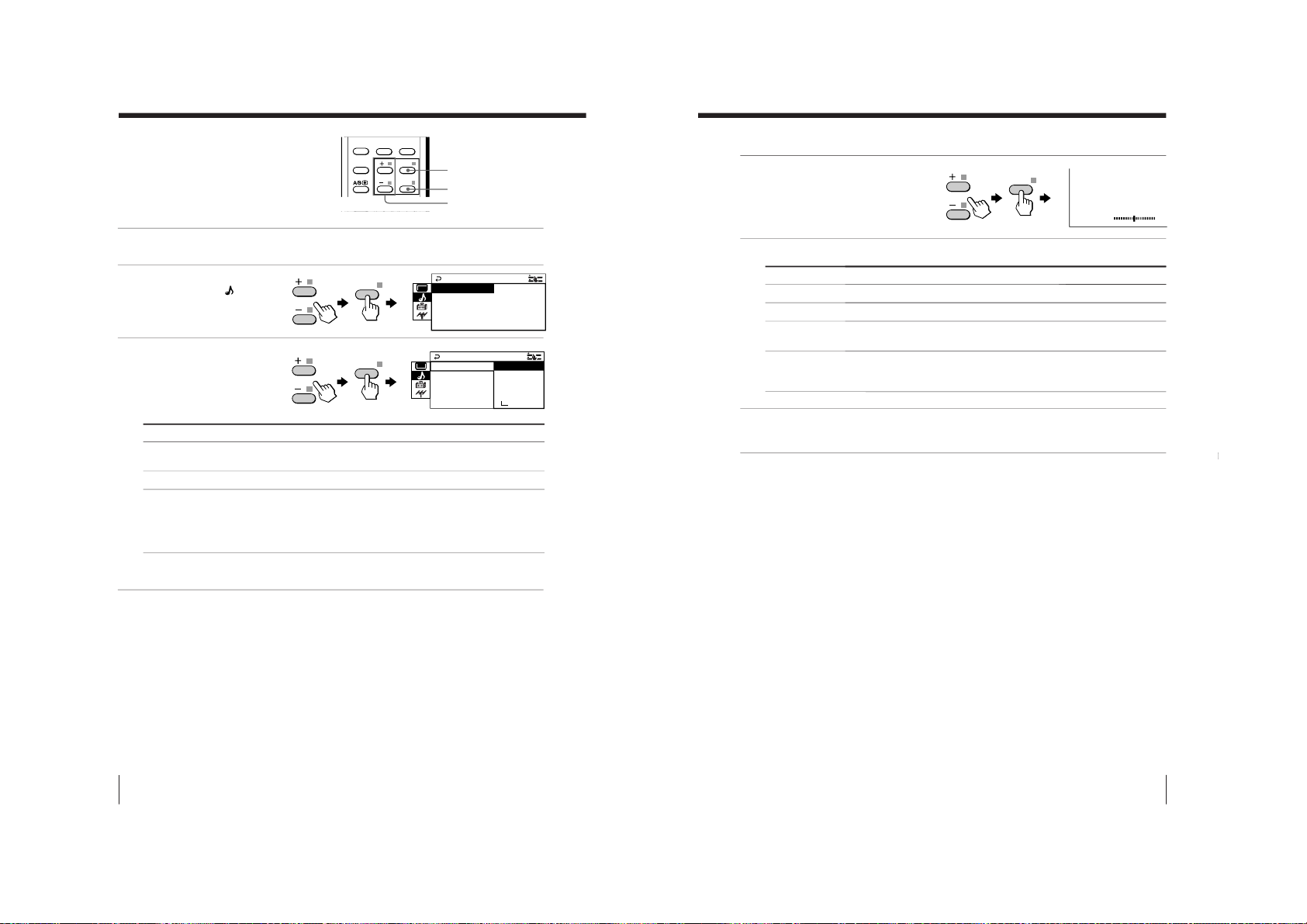
Changing the
“SOUND” setting
The “SOUND” menu allows you to adjust
the sound settings.
1
Press MENU.
2
Press + or – to select the
“SOUND” icon (
),
then press ENTER.
3
Press + or – to select
the desired item (e.g.,
“SOUND MODE
”),
then press ENTER.
* When the “PERSONAL” mode is selected, you can r
eceive the last
adjusted sound settings from the “ADJUST” option (see page 29).
Note
• For details on the options under
“SOUND MODE
” and “SURROUND”,
see pages 15 and 18 respectively.
To return to the normal screen
Press MENU.
SOUND MODE
SOUND
INTELL I GENT VOL: OFF
SUR ROU ND :OFF
: DYNAMI C
SOUND MODE
PE
SOUND
RSONAL
INTEL LIGENT SOF T
DRAMA
SUR ROU ND :OF
:
ADJ UST
DYNAMI C
Select
“SOUND MODE”
“SURROUND”
“INTELLIGENT
VOL”
MENU
FAVORITE
SOUND
MODE
PIC MODE
PROGR
ENTER
MENU
SURROUND
ENTER
+/–
To
choose either “DYNAMIC”, “DRAMA”, “SOFT”, “PERSONAL”*, or
“ADJUST”.
choose either “TruSurround” or “OFF”.
adjust the volume of all TV programs and video inputs
automatically.
Press + or – to select “ON”, then press ENTER.
To cancel, select “OFF”, then pr
ess ENTER.
ENTER
ENTER
29
Adjusting Your Setup (MENU)
Adjusting Your Setup (MENU)
Adjusting the
“ADJUST” items under
“SOUND MODE
”
1
Press + or – to select
the desired item (e.g.,
“BALANCE”),
then press ENTER.
2
Adjust the value according to the following table, then press ENTER .
3
Repeat the above steps to adjust other items.
The adjusted settings will be received when you select
“PERSONAL”.
Tip
• For details on the menu system and how to use the menu, refer to
Introducing the menu system on page 23.
BALANCE
00
For
“BASS”
“TREBLE”
“BALANCE”
“BBE”
Press – to Press + to
decrease the bass increase the bass.
decrease the treble increase the treble.
increase the left speaker’s increase the right speaker’s volume.
volume
select “HIGH” for higher enhancement of sound clarity;
select “LOW” for lower enhancement of sound clarity;
select “OFF” to turn off the BBE sound.
ENTER
RM-964
– 20 –
Page 22
30
Adjusting Your Setup (MENU)
Changing the
“SETUP” setting
The “SETUP” menu allows you to
change the menu language, adjust the
picture position, reduce your TV power
consumption, setup your programs and
select the color system.
1
Press MENU.
2
Press + or – to select
the “SETUP” icon (
),
then press ENTER.
3
Press + or – to select
the desired item
(e.g., “COLOR SYS”),
then press ENTER.
To return to the normal screen
Press MENU.
MENU
Number buttons
1
4
7
2
5
8
0
3
6
9
FAVORITE
SOUND
MODE
PIC MODE
PROGR
ENTER
MENU
SURROUND
JUMP
E
COLOR SYS : AUTO
SETUP
PROGRAM SETUP
PIC ROTA T I ON
NGL I SH
ECO MODE :OF F
L ANGU AGE :
ENTER
Select
“LANGUAGE”
“PIC ROTATION”
“ECO MODE”
“PROGRAM
SETUP”
“COLOR SYS”
E
COLOR SYS : NT
SETUP
SC3 . 5 8
PROGRAM SET N
ECAM
PIC ROTA T I O PAL
N AUTO
ECO MODE :OF S
T
SC4 . 4 3
L ANGU AGE :
To
change the menu language (see Changing the menu language on page 13).
adjust the picture position when it is not aligned with the TV screen.
Press + or – to adjust the picture position, then press ENTER.
reduce power consumption of your TV to save energy.
Press + or – to select “ON”, then pr
ess ENTER.
To cancel, select
“OFF”, then pr
ess ENTER.
adjust each channel settings (see Adjusting each channel settings
(PROGRAM SETUP) on page 31).
select the color system. Normally, set this to “AUTO”.
+/–
ENTER
ENTER
PIC ROTATION
b
b
ENTER
31
Adjusting Your Setup (MENU)
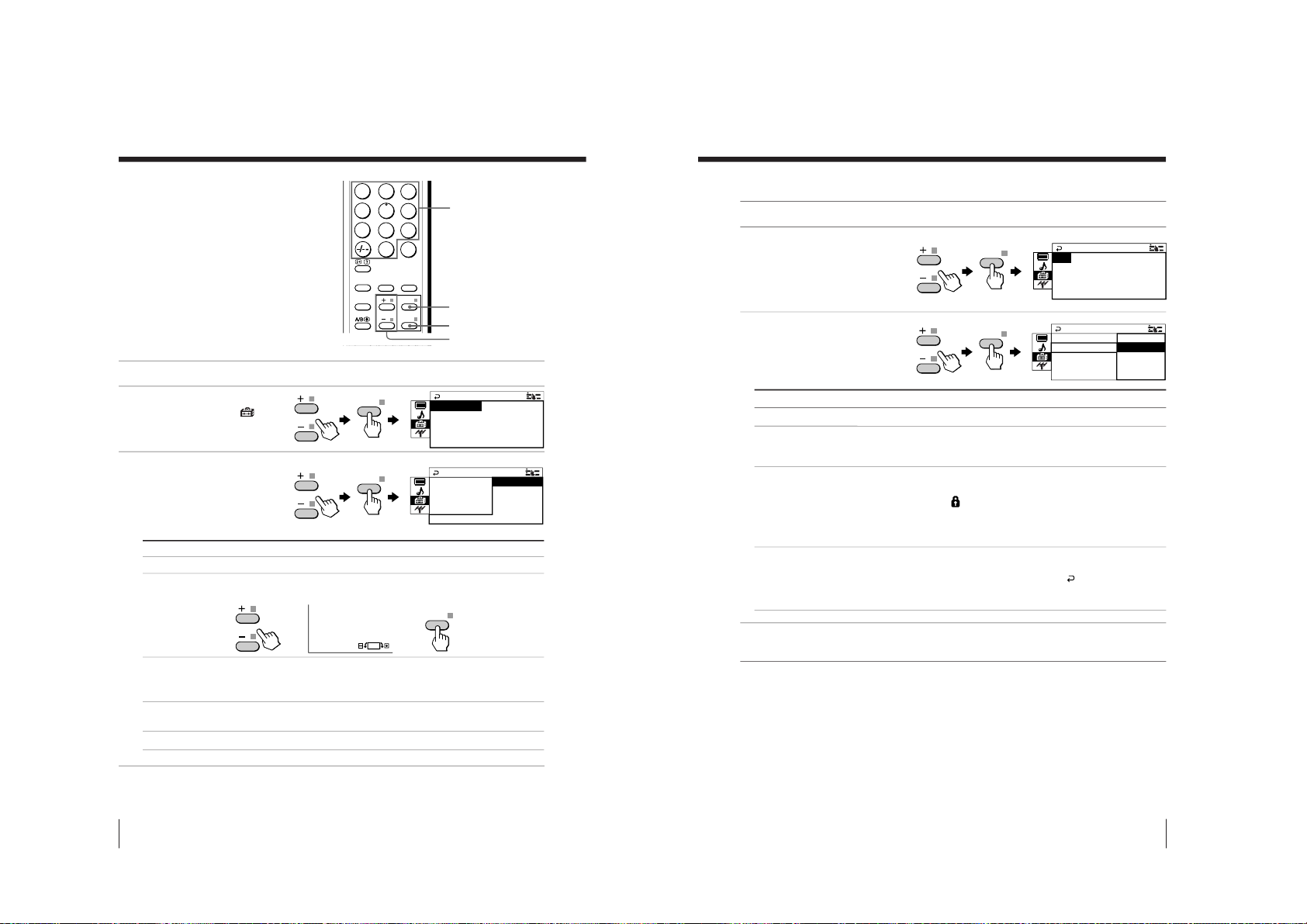
Adjusting each channel settings (PROGRAM SETUP)
1
Select “PROGRAM SETUP
” from the “SETUP” menu.
2
Select “PR” and press
ENTER. Press + or
– to
select the desired
channel you want to
adjust, then press ENTER.
3
Press + or – to select
the desired item
(e.g., “SKIP”), then
press ENTER.
Select To
“PR” select the desired channel.
“SKIP” skip unwanted or unused program number.
Press + or – to select “ON”, then pr
ess ENTER.
To cancel, select “OFF”, then pr
ess ENTER.
“CHILD LOCK”
prevent children from watching this selected channel.
Press + or – to select “ON”, then pr
ess ENTER.
The lock symbol (
) appears on the screen.
To cancel, select
“OFF”, then pr
ess ENTER.
If you preset a locked channel, that channel will be unlocked
automatically.
“FAVORITE CH” program six channels for direct selection.
Press + or – to select one of the six favorite channel numbers (if
you decide not to make any changes, select
“
”), then press
ENTER.
To view the selected favorite channel, refer page 17.
4
To continue adjusting other channels, press + or – to select “PR”, then r
epeat
step 2 and 3.
To return to the normal screen
Press MENU.
UP
FAVOR I TE CH : ––
PROGRAM S E T
CH I L D L OCK :OF F
SK I P :OFF
PR : 14
UP
FAVOR I TE CH
PROGRAM S E T
CH I L D L OCK :
SK I P OFF
ON
PR :
:
1 4
ENTER
ENTER
– 21 –
KV-EX29M61
RM-964
Page 23
32
Adjusting Your Setup (MENU)
Changing the
Channel Preset
(“CH PRESET”)
setting
The “CH PRESET” menu allows you to
adjust the setup of your TV. For
example, you can manually tune in a
channel with a weak signal that fails to
be tuned in by automatic presetting.
1
Press MENU.
2
Press + or – to select the
“CH PRESET” icon (
),
then press ENTER.
3
Press + or – to select
the desired item (e.g.,
“AUTO PROGRAM
”),
then press ENTER.
To return to the normal screen
Press MENU.
Tip
• For details on the menu system and how to use the menu, refer to
Introducing the menu system on page 23.
Select
“AUTO PROGRAM”
“MANUAL PROGRAM
”
“TV SYS”
To
preset channels automatically.
preset channels manually. See Presetting channels
manually on page 33.
select the TV system.
Press + or – to select either “B/G”, “I”, “D/K” or “M”, then
press ENTER.
M
PR : 0 1
AUTO PROGRA
VHF LOW
TV SYS:AUTO
CH PRESE T
TV SYS:B/G
MANUAL PROGRAM
AUTO PROGR
AM
MENU
1
4
7
2
5
8
0
3
6
9
FAVORITE
SOUND
MODE
PIC MODE
PROGR
ENTER
MENU
SURROUND
JUMP
ENTER
+/–
ENTER
ENTER
33
Adjusting Your Setup (MENU)
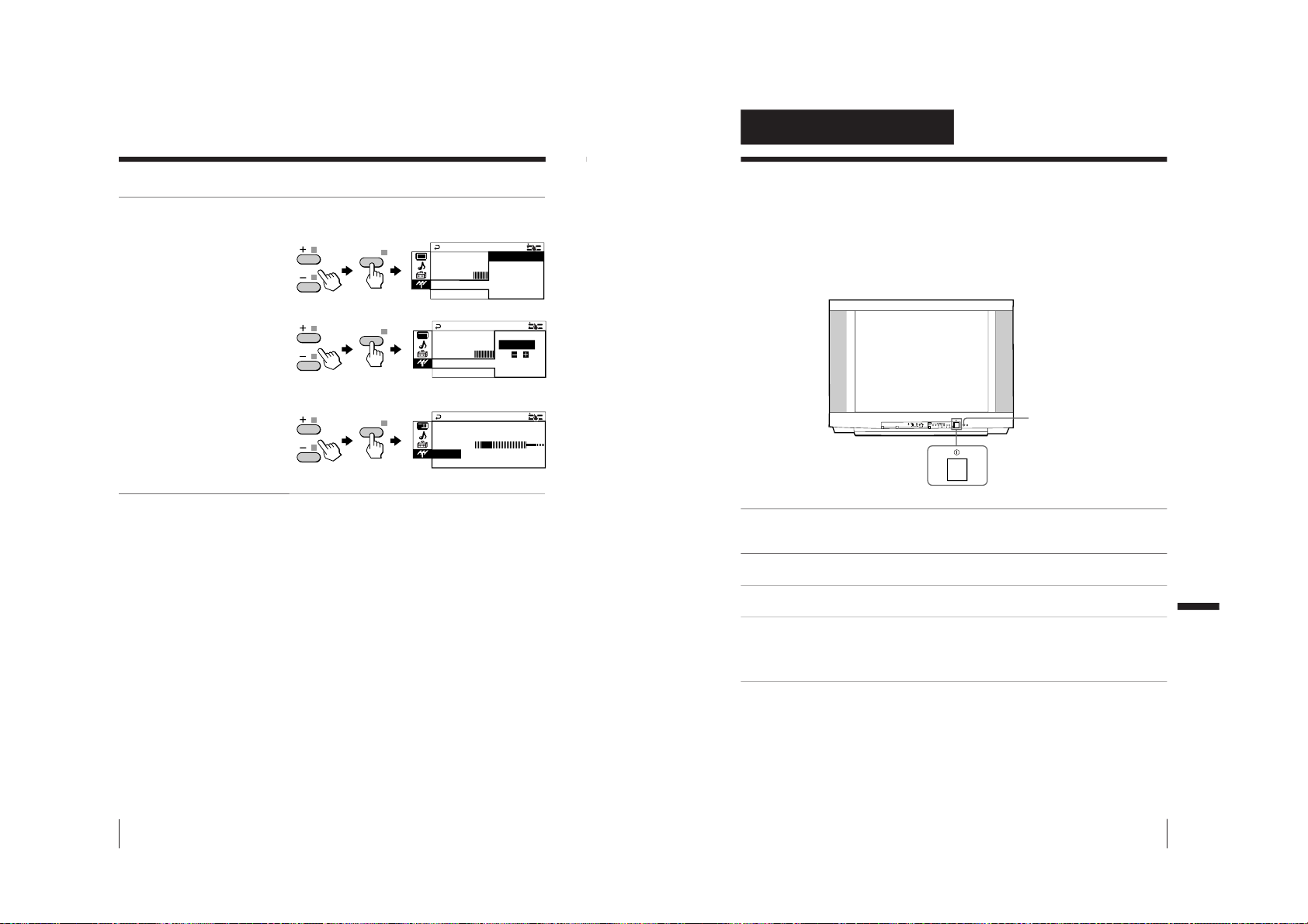
Presetting channels manually
1
After selecting
“MANUAL
PROGRAM”, select the
program number to
which you want to preset
a channel.
(1) Make sure “PR” is selected,
then press ENTER.
(2) Press + or – until the
program number you
want to preset (e.g.,
program number
“10”) appears on
the
menu, then press
ENTER
.
Tip
• You can also select the
program number with the
PROGR +/– or number
buttons.
2
Select the desired channel.
(1)
Press
+ or –
to select
either “VHF LOW”,
“VHF HIGH”,
or “UHF”, then
press ENTER.
(2) Press + or – until the
desired channel’s
broadcast appears
on the TV screen,
then press ENTER.
3
If the sound of the
desired channel is
abnormal, select the
appropriate TV system.
(1) Press + or – to
select “TV SYS”,
then press ENTER.
(2) Press + or – until
the sound becomes
normal, then
press ENTER.
MANU A L PROGRAM
PR
:
06
TV SYS
:
B/G
VHF LOW
FINE
:
AUTO
MANUAL PROGRAM
PR
:
10
TV SYS
:
B/G
VHF LOW
FINE
:
AUTO
MANU A L PROGRAM
PR
:
10
TV SYS
:
B/G
VHF LOW
FINE
:
AUTO
MANU A L PROGRAM
PR
:
10
TV SYS
:
B/G
VHF LOW
FINE
:
AUTO
MANU A L PROGRAM
PR
:
10 B/G
TV SYS
:
I
D/K
VHF LOW
M
FINE
:
AUTO
MANU A L PROGRAM
PR
:
10
TV SYS
:
I
VHF LOW
FINE
:
AUTO
continued
ENTER
ENTER
ENTER
ENTER
ENTER
ENTER
– 22 –
KV-EX29M61
RM-964
Page 24
34
Adjusting Your Setup (MENU)
4
If you are not satisfied with
the picture and sound
quality, you may be able to
improve them by using the
“FINE” tuning feature.
(1) Press + or –
to select “FINE”,
then press ENTER.
(2) Press + or – to select
“MANUAL”, then
press ENTER.
(3) Press + or –
until the picture
and sound quality
are optimal, then
press ENTER.
The + or – icon on
the menu flashes
while tuning.
To return to the normal screen
Press MENU.
Notes
• The TV system (
“TV SYS”) and fine tuning (
“FINE”) settings ar
e
memorized for each program number.
• If you preset a locked channel (
“CHILD LOCK”), that channel will be
unlocked automatically (see page 31).
MANU A L PROGRAM
PR
:
10
TV SYS
:
I MANUAL
VHF L OW
FINE
:
AUTO
MANU A L PROGRAM
PR
:
10 AUTO
TV SYS
:
I L
VHF LOW
FINE
:
MANU A
MANU A L PROGRAM
PR
:
10
TV SYS
:
I
VHF L
L
OW
FINE
:
MA
A
N
U
Changing the “CH PRESET” setting (continued)
ENTER
ENTER
ENTER
35
Additional Information
Additional Information
Additional Information
Self-diagnosis function
Your TV is equipped with a self-diagnosis function. If there is a
problem with your TV, the 1 (standby) indicator flashes red. The
number of times the 1 indicator flashes indicates the possible
causes.
1
Check that the 1 indicator flashes red a number of times between 3-second
intervals.
2
Count the number of times the 1 indicator flashes.
3
Press ! (main power) to turn off your TV.
4
Inform your nearest Sony service center about the number of times the
1 indicator flashed.
Be sure to note the model name and serial number located on the rear of
your TV.
Front of TV
1
indicator
L(MONO) R
4
PROGRMENU
AUTO
PROGR
ENTER SELECT
– 23 –
KV-EX29M61
RM-964
Page 25
36
Additional Information
Troubleshooting Shortcuts
For better viewing, please check the following connections.
• Snowy • Distorted • Noisy/
picture picture distorted
sound
Wall antenna
terminal
UHF
VHF
Booster
VCR
Check the antenna direction.
Incorrect antenna direction may cause:
Check the
antenna type.
Wrong type of antenna
may cause:
• No picture
• Snowy picture
Check connection
on the wall antenna
terminal.
Loose connection may
cause:
•
Snowy picture
• Distorted sound
Check if you need
booster to increase
signal level.
Too strong signal level
may cause:
•
Distorted picture
• Noisy sound
Antenna connection
37
Additional Information
Additional Information
P166 SECTEXT 166 FR1 MAR 03:59:09
Fom Singapore
To PARIS
To OSAKA
To ROMA
To SYDNEY
Day Dep/Arr Flight Alrcraft
1.6 220/0588 SQ28 747
2 2130/1225 PA115 L15
3 2115/1330 SQ26 747
2.7 2130/0745 SQ24
747
4 2300/0915 AZ487 747
2.5 1000/1715 SQ6 747
4.6 0930/2015 CX522 L10
1 2210/0610 SQ21A 747
2 2100/0835 SQ21A 747
Connection
to TV
For more information, please see
Troubleshooting on page 38 or consult
your dealer for guidance.
• Double
image
picture
Check connection
on the VCR and on
the TV.
Loose connection may
cause:
• Snowy picture
• Distorted sound
• No picture
• Missing
Teletext
characters
AC Connection
Check connection on
the AC socket.
Loose connection may cause:
• no power
• no picture with no sound
KV-EX29M61
RM-964
– 24 –
Page 26
38
Additional Information
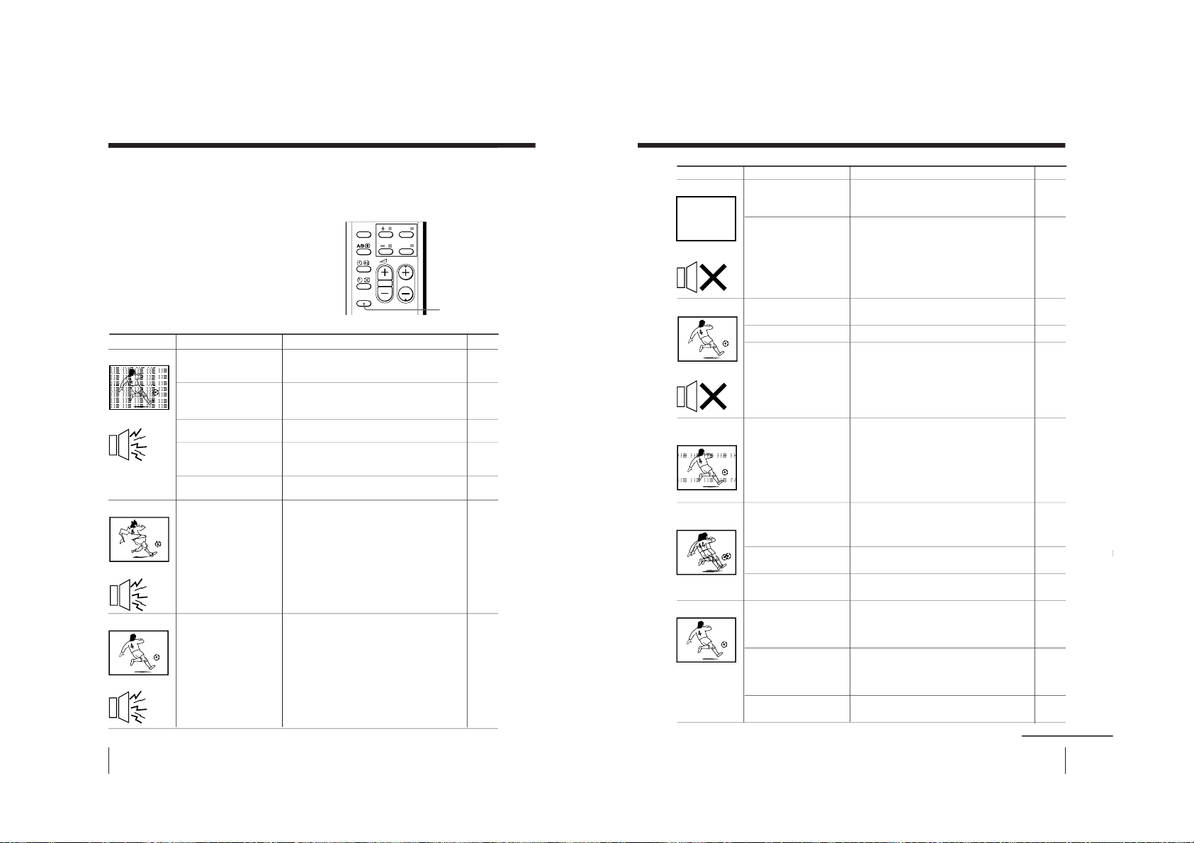
Troubleshooting
If you have any problem while viewing your TV, you can either use the Reset function or
check the Troubleshooting guide below. If the problem persists, contact your Sony dealer.
Reset function
Press the RESET button on your remote control.
Your TV will go blank for about half a second
then the picture will reappear with “RESET”
displayed on your TV screen for about 10 seconds.
Pressing RESET will set your TV to the factory
setting, but certain problems may be solved.
Troubleshooting guide
• Check the antenna cable and
connection on the TV, VCR and at the
wall.
• Display the “CH PRESET” menu and
select “MANUAL PROGRAM
” to
preset the channel again.
• Check the antenna type (VHF/UHF).
Contact a Sony dealer for advice.
• Adjust the antenna direction. Contact
a Sony dealer for advice.
• Try using a booster.
• Turn off or disconnect the booster if it
is in use.
• If the sound of all the channels are noisy,
display the “CH PRESET” menu and
select “AUTO PROGRAM” to preset the
channels again.
• If the sound of some channels is noisy,
select the channel, then display the
“CH PRESET” menu and select the
appropriate TV system (
“TV SYS”).
Possible cause
Symptom
Solutions
Snowy picture
Noisy sound
Distorted picture
Noisy sound
Good picture
Noisy sound
Page
4
33
–
–
–
–
32
33
• The connection is
loose or the cable is
damaged.
• Channel presetting
is inappropriate or
incomplete.
• The antenna type is
inappropriate.
• The antenna
direction needs
adjustment.
• Signal transmission is
low.
• Broadcast signals
are too strong.
• The TV system
setting or channel
presetting is
inappropriate or
incomplete.
RESET
PIC MODE
PROGR
ENTER
MENU
RESET
39
Additional Information
Additional Information
• Check the power cord, antenna and
the VCR connections.
• Press ?/1 (power).
• Press ! (main power) on the TV to
turn off the TV for about five
seconds, then turn it on again.
• Press ¸ + to increase the volume
level.
• Press % to cancel the muting.
• Press A/B until a better sound is
heard.
• Do not use a hair dryer or other
equipment near the TV.
• Adjust the antenna direction for
minimum interference. Contact a
Sony dealer for advice.
• Use a highly directional antenna.
• Use the fine tuning (
“FINE”) function.
• Adjust the antenna direction.
Contact a Sony dealer for advice.
• Turn off or disconnect the booster if
it is in use.
• Display the “PICTURE” menu and
select “ADJUST” of “PICTURE
MODE”, then adjust the
“COLOR”
level.
• Display the “SETUP” menu and
check the color system (
“COLOR
SYS”) setting (usually set this to
“AUTO”).
• Adjust the antenna direction.
Contact a Sony dealer for advice.
Possible cause
Symptom
Solutions
4
11
12
12
12
19
–
–
–
34
–
–
27
30
–
continued
No picture
No sound
Good picture
No sound
Dotted lines or
stripes
Double images or
“ghosts”
No color
• The power cord,
antenna or VCR is
not connected.
• The TV is not turned
on.
• The volume level is
too low.
• The sound is muted.
• The broadcast signal
has a transmission
problem.
• There is local
interference from
cars, neon signs, hair
dryers, power
generators, etc.
• Broadcast signals are
reflected by nearby
mountains or buildings.
• The antenna direction
needs adjustment.
• Use of a booster is
inappropriate.
• The color level
setting is too low.
• The color system
setting is
inappropriate.
• The antenna direction
needs adjustment.
Page
– 25 –
KV-EX29M61
RM-964
Page 27
KV-EX29M61
40
Additional Information
Troubleshooting (continued)
Possible cause
Symptom Solutions
• Keep external speakers or other
equipment away from the TV. Do not
move the TV while the TV is turned
on. Press ! (main power) on the TV
to turn off the TV for about five
minutes, then turn it on again.
• Press A/B until “AUTO” appears on
the screen.
• Check the antenna cable and
connection on the TV, VCR and on
the wall.
• Adjust the antenna direction. Contact
a Sony dealer for advice.
• Press A/B until a better sound is heard.
—
• Check the antenna cable and
connection on the TV, VCR, and at the
wall.
• Adjust the antenna direction. Contact a
Sony dealer for advice.
• Try using a booster.
• Use the fine tuning (
“FINE”) function.
• Keep external speakers or other electrical
equipment away from the TV.
• Display the “SET UP” menu and adjust
“PIC ROTATION” until the picture
position is optimal.
Abnormal color
patches
TV cannot receive
stereo broadcast
signal.
Stereo broadcast
sound switches
on and off or
is distorted.
or
The sound switches
between stereo and
monaural
frequently.
“100” appears at
the top of the
screen and there is
no Teletext display.
Teletext display is
incomplete
(snowy picture or
double images).
Picture slant
• The magnetic
disturbance from
external speakers or
other equipment, or
the direction of the
earth’s magnetic
field may affect the
TV.
• The stereo reception
setting is
inappropriate.
• The connection is
loose or the cable is
damaged.
• The antenna direction
needs adjustment.
• The broadcast signal
has a transmission
problem.
• The channel carries no
Teletext broadcast.
• Connection is loose or
the cable is damaged.
• The antenna direction
is inappropriate.
• Signal transmission
is too low.
• The magnetic
disturbance from
external speakers or
other equipment, or
the direction of the
earth’s magnetic
field may affect the
TV.
Page
–
19
4
–
19
21
4
–
–
34
–
30
Good morning!
41
Additional Information
Additional Information
Possible cause
Symptom
Solutions
• Use the fine tuning (
“FINE”) function.
• Contact your nearest Sony service
center.
—
—
—
Lines moving across
the TV screen.
The 1 indicator on
your TV flashes red
a number of times
between 3-second
intervals.
Cannot play
shooting games.
TV cabinet creaks.
A small “boom”
sound is heard
when the TV is
turned on.
34
35
–
–
–
Page
• There is interference
from external sources,
e.g., heavy
machineries, nearby
broadcast station.
• Your TV may need
servicing.
• Some shooting games
which involve pointing
a light beam at the TV
screen with an
electronic gun or rifle
cannot be used with
your TV. For detail, see
the instruction manual
supplied with the
video game software.
• Changes in room
temperature sometimes
make the TV cabinet
expand or contract,
causing a noise. This
does not indicate a
malfunction.
• The TV’s
demagnetizing
function is working.
This does not indicate a
malfunction.
RM-964
– 26 –
Page 28
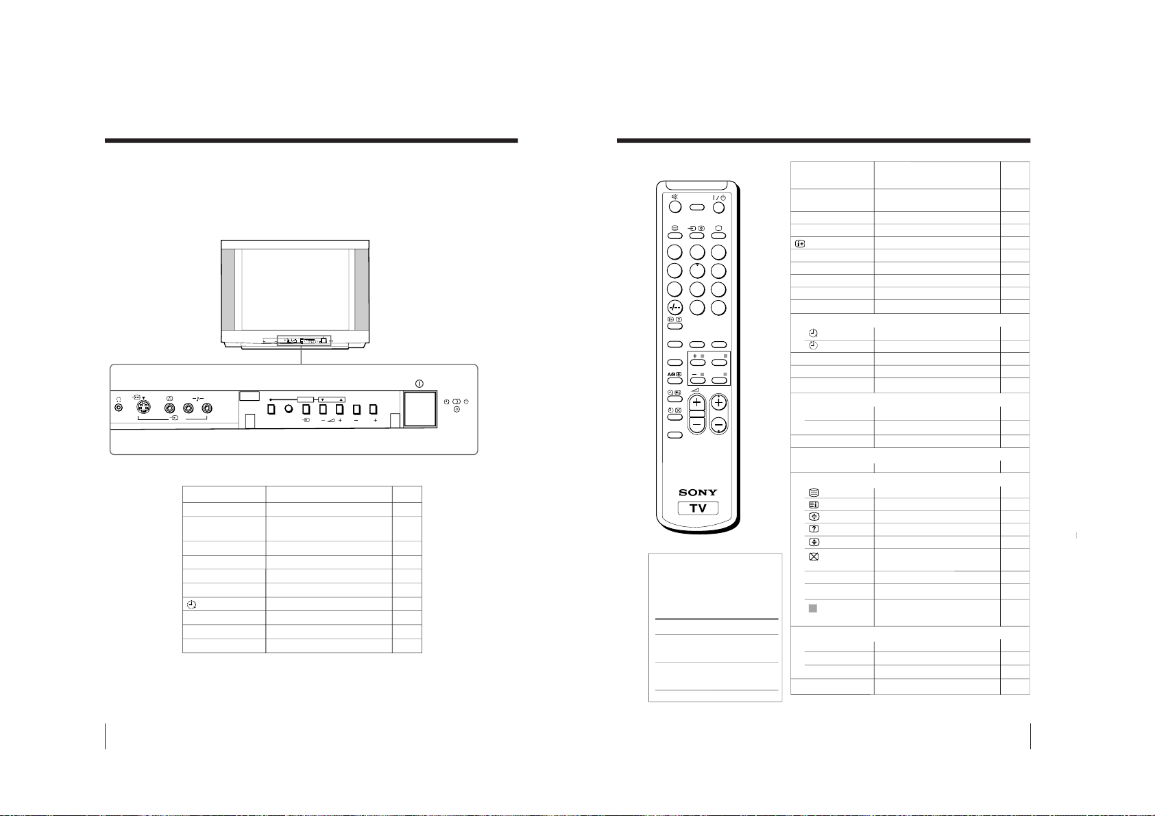
42
Additional Information
Preset channels automatically.5
Turn off completely or 11
turn on the TV.
Select program number. 11
Standby indicator.11
Adjust volume. 12
Select TV or video input. 12
Wake Up indicator.14
Stereo/Bilingual indicator.19
Display the menu. 25
Headphone jack. –
Overview of controls
TV front panel
L(MONO) R
4
PROGRMENU
AUTO
PROGR
ENTER SELECT
L(MONO) R
4
PROGRMENU
AUTO
PROGR
ENTER SELECT
PageFunction
Button
AUTO PROGR
!
PROGR +/–
1
2
+/–
t
Â
MENU
i
43
Additional Information
Additional Information
?/1
PROGR +/–
0 – 9, ÷
¤
;
t
. +/–
JUMP
Timer operation
SOUND MODE
PIC MODE
DRC-MF
Favorite Channel operations
FAVORITE
1 – 6
SURROUND
Stereo/bilingual operations
A/B
Teletext operations
0 - 9
PROGR +/–
(red, green,
yellow, blue)
Menu operations
MENU
+, –
ENTER
RESET
Turn off temporarily or 11
turn on the TV.
Select program number. 11
Input numbers. 11
Display on-screen information. 12
Mute the sound. 12
Display the TV program. 12
Select TV or video input. 12
Adjust volume. 12
Jump to previous channel. 12
Set TV to turn on automatically.
14
Set TV to turn off automatically. 14
Select sound mode. 15
Select picture mode. 15
Select DRC-MF mode. 16
Display favorite channels. 17
Select desired channel. 17
Select surround mode. 18
Select stereo/bilingual mode. 19
Display Teletext broadcast. 21
Display Teletext service contents.
22
Stop Teletext display from scrolling.
22
Reveal concealed information. 22
Enlarge the Teletext display. 22
Show TV screen while waiting
22
for Teletext page.
Input Teletext page number.22
Display the next or previous page.
22
Access a FASTEXT menu. 22
Display the menu. 25
Select and adjust items. 25
Confirm selected items. 25
Set TV to factory setting. 38
Page
Button
Function
Remote control
1
4
7
2
5
8
0
3
6
9
FAVORITE
SOUND
MODE
RESET
PIC MODE
PROGR
DRC-MF
ENTER
MENU
SURROUND
JUMP
Button function
For general TV
operations
For Teletext
operations
The names/symbols of
buttons on the remote are
indicated in different colors
to represent the available
functions.
Label color
White
Green
– 27 –
KV-EX29M61
RM-964
Page 29
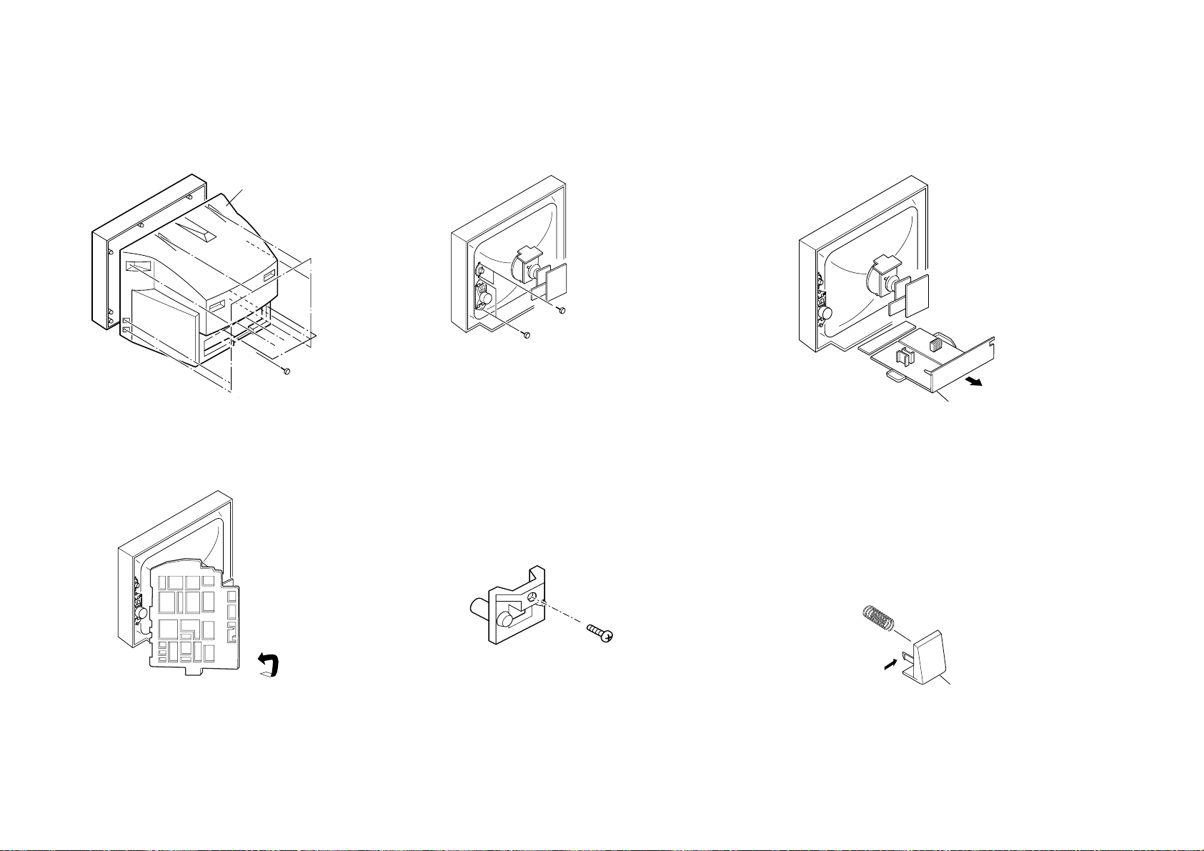
KV-EX29M61
2 Rear cover
1 Twelve screws
(+BVTP 4 × 16)
1Two screws (+BVTP 4
× 16)
2Two screws (Washer head)
1 Chassis assy
One screw
(+BVTP 3 × 12)
Power Button
– 28 –
2-1. REAR COVER REMOVAL
2-4. SERVICE POSITION
SECTION 2
DISASSEMBLY
2-2. SPEAKER REMOVAL
2-5. REPLACEMENT OF PARTS
For Power Button removal, push the claw in the
direction of the arrow and remove.
RM-964
2-3. CHASSIS ASSY REMOVAL
Note:
1. Disconnect the DGC connector from CN6603 (D board)
2. Disconnect Lead Assy Speaker (R) from Relay.
3. Undress necessary wires that creates tension while
placing the chassis into Service Position.
2-5-1. Replacement of Light Guide
2-5-2. Replacement of Power Button
Page 30
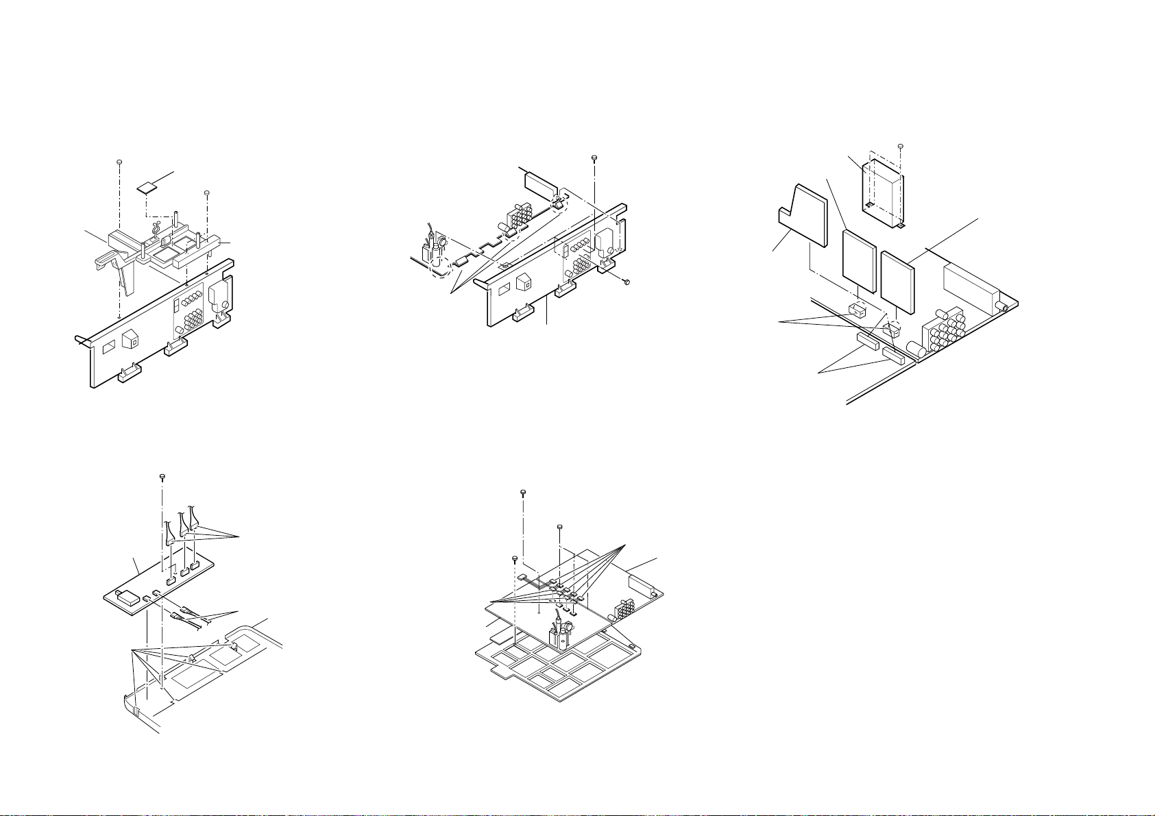
2-6. PWB AND DH BOARDS REMOVAL
PWB holder
1 Two screws
(+BVTP 3 × 12)
1 One screw
(+BVTP 3 x 12)
2 DH Board
1 Six screws
(+BVTP 3 × 12)
One screw
(+BVTP 4 × 16)
3 Three claws
4 Terminal bracket
1 Two claws
6 Two connectors
2 Metal Case
Two screws (+BVTP 3 x 12)
5 V2 board
7 D1 board
3 B3 board
3 Three connectors
6 One screw
(3 × 12)(+)BVTAP
1 Two connectors
4 Six claws
5 H1 Board
5 A Board
4 D Board
1 Three screws
(3 x 12)(+BVTAP)
2 One screw
(3 x 12)(+BVTAP)
7 One screw
(3 x 12)(+BVTAP)
(Washer Dia. 15)
3 Four connectors
6 Five connectors
2-7. TERMINAL BRACKET REMOVAL
2-8. B3, V2 AND D1 BOARDS REMOVAL
– 29 –
2-9. H1 BOARD REMOVAL
2-10. A AND D BOARDS REMOVAL
KV-EX29M61
RM-964
Page 31

KV-EX29M61
0 Four DGC clips
!£ DGC
band
!¡ Demagnetic coil
!™ Four claws
1 Two screws
(washer head)
(+P 4 × 16)
4 Speaker
(5cm)
@ºTwo nuts,
special, CRT
2 Speaker
(15 × 6.5cm)
8 Speaker
(5cm)
6 Speaker
(15 × 6.5cm)
!• Tension
spring
9 Chassis assy
!¶ Deflection
yoke
!§ Neck assy
!∞ C board
!¢ Anode cap
@¡ Picture tube
Cushion
@º Two nuts,
special, CRT
3 Two screws
(+BVTP 4 × 16)
5
7
Two screws
(washer head)
(+P 4 × 16)
Two screws
(+BVTP 4 × 16)
!ª Cap,
screw
!ª Cap,
screw
– 30 –
2-11. PICTURE TUBE REMOVAL
Note:
i) When removing the Nut, Locking; first make sure to hold the screw, special CRT
with a spanner (diameter 6) while opening the Nut, Locking using a spanner. Then
proceed to remove the Nut, special CRT using a torque driver.
ii) Remove all the necessary CRT supports located on top left and right, bottom left
and right prior to removing the CRT.
• REMOVAL OF ANODE-CAP
RM-964
NOTE : After removing the anode, short circuit the anode of the picture tube and
the anode cap to the metal chassis, CRT shield or carbon paint on the
CRT.
• REMOVING PROCEDURES
a
a
1 Turn up one side of the rubber cap in the direction indicated by the arrow a.
b
b
2 Using a thumb pull up the rubber cap firmly in the direction indicated by the arrow b.
c
Anode button
3 When one side of the rubber cap is separated from the anode button, the anode-cap
can be removed by turning up the rubber cap and pulling it up in the direction of the
arrow c.
• HOW TO HANDLE AN ANODE-CAP
1 Do not damage the surface of anode-caps with sharp shaped objects.
2 Do not press the rubber too hard so as not to damage the inside of anode-cap.
A metal fitting called the shatter-hook terminal is built into the rubber.
3 Do not turn the foot of rubber over too hard.
The shatter-hook terminal will stick out or damage the rubber.
Page 32

SECTION 3
SERVICE JIG
3-1. JIGS REQUIRED FOR SERVICING
REF NO. DESCRIPTION PART NO. REMARK
J-1 TOOL (20P), SERVICE 3-702-763-01 For A to V2 board extension
J-2 TOOL (40P), SERVICE 3-702-764-01 For B3 to A board extension
J-3 TOOL (30P), SERVICE 3-702-773-01 For D to D1 board extension
KV-EX29M61
RM-964
J-1
EX
J-2
EX
EX
1
2
3
EX
4
J-3
EX
9
EX
10
SECTION 4
CIRCUIT BOARDS LOCATION
H1
C
VM
F1
B3
V2
D1
A
DH
J
D
– 31 –
Page 33

KV-EX29M61
RM-964
SECTION 5
ADVANCE OPERATION
5-1. "RESET" FUNCTION
Purpose
1.
If a customer faces some setting problem that cannot be solved, using the "RESET" function some items
will be reset to its original setting (shipping condition).
2.
How to Operate
There are 2 ways to access to the "RESET" Function:-
a) By pressing "RESET" button on the Remote Commander.
b) By pressing "MENU" button or "SELECT" button (for non-menu models) on the Front Key Input
and hold it down for 5 seconds.
3. Subsequent of Operation
Sequential to the resetting operation (either methods being used in No. 2), TV set would shut down once
and automatically turn on again. The power-off duration is expected to be about 500msec. An OSD
message, "RESET" tentatively will be displayed for 10 sec after IK status gets stable.
As a result, some items will be reset to an initial condition (shipment condition) wheareas some other
remains at the last selection by user.
Items that remains at the last selection by user
Program No., Favourite CH Setup, PIC rotation,
OSD Language, Fine tuning, TV System, Skip
Reset Items
Video input RF
Volume 30
DRC-MF DRC1250
Picture mode DYNAMIC
Sound mode DYNAMIC
Surround mode OF
Color system(video) AUTO
Multi picture(PIP) OFF
PIP position Bottom-right
Favourite CH mode AUTO
OSD recall OFF
Intelligent volume OFF
ECO mode OFF
*= only when in RF mode
Color system(RF) AUTO*
Antenna sensitivity HIGH*
Stereo mode STEREO/NICAM*
Bilingual mode MAIN*
High-deviation mode AUTO*
Child lock OFF*
Wide mode OFF
Game mode OFF
Teletext mode OFF
Sleep timer OFF
Wake-up timer OFF
Sound muting OFF
– 32 –
Page 34

SECTION 6
Red
Blue
Green
SET-UP ADJUSTMENTS
KV-EX29M61
RM-964
• The following adjustments should be made when a
complete realignment is required or a new picture tube is
installed.
• These adjustments should be performed with rated power
supply voltage unless otherwise noted.
Controls and switches should be set as follows unless otherwise
noted:
PICTURE control ........................................................... normal
BRIGHTNESS control ................................................... normal
................................................................................................................................................................................................................................
Preparation :
• In order to reduce the influence of geomagnetism on the
set's picture tube, face it east or west.
• Switch on the set's power and degauss with the degausser.
Perform the adjustments in the following order :
1. Beam Landing
2. Convergence
3. Focus
4. White Balance
Note : Test Equipment Required.
1. Color-bar/Pattern Generator
2. Degausser
3. Oscilloscope
6-1. BEAM LANDING
1. Input a white signal with the pattern generator.
Contrast
Brightness
2. Position neck assy as shown in Fig6-1.
3. Set the pattern generator raster signal to a green raster.
4. Move the deflection yoke to the rear and adjust with the
purity control so that the green is at the center and the blue
and the red take up equally sized areas on each side.
(See Figures 6-1 through 6-3.)
5. Move the deflection yoke forward and adjust so that the
entire screen is green. (See Figure 6-2.)
6. Switch the raster signal to blue, then to red and verify the
condition.
7. When the position of the deflection yoke has been
decided, fasten the deflection yoke with the screws and
DY spacers.
8. If the beam does not land correctly in all the corners, use a
magnet to adjust it.
}
normal
Neck assy
Purity control
corrects this area.
b
c
a
d
Fig. 6-2
Fig. 6-3
Disk magnets or rotatable
disk magnets correct these
areas (a-d).
Deflection yoke positioning
corrects these areas.
Behind the G2 edge
b
c
G2G1 G3
a
Fig. 6-1
d
Fig. 6-4
– 33 –
Page 35

KV-EX29M61
RM-964
6-2. CONVERGENCE ADJUSTMENT
Preparation :
• Before starting this adjustment, adjust the focus, horizontal
size and vertical size.
• Set the PICTURE 70% and BRIGHTNESS 0%.
• Cross hatch / Dot pattern.
(1) Horizontal and Vertical Static Convergence
Center dot
R G B
H. STAT VR
R
G
B
V. STAT
Magnet
Y magnet
1 V. S TAT
a
b b
2 H. STAT VR
a
RGGBB
b
a
B
G
R
R
b
B
G
R
RV702
H. STAT
C Board
1. (Moving horizontally), adjust the H.STAT control so that
the red, green and blue dots are on top of each other at the
center of the screen.
2. (Moving vertically), adjust the V.STAT magnet so that the
red, green and blue dots are on top of each other at the
center of the screen.
3. Adjust Horizontal Trapezoid with “DAC 04 HTR” in
Service Mode to make H-Trapezoid distortion best.
4. If the H.STAT variable resistor cannot bring the red, green
and blue dots together at the center of the screen, adjust
the horizontal convergence with the H.STAT variable
resistor and the V.STAT magnet in the manner given
below.
(In this case, the H.STAT variable resistor and the V.STAT
magnet influence each other, so be sure to perform
adjustments while tracking.)
3
a
b
a
R
b
Purity
B
BMC (Hexapole)
V.STAT
b
B
GG
R
– 34 –
Page 36

KV-EX29M61
R
(B)B(R)
B
(R)
TLH +
TLH -
R
(B)
RM-964
4 BMC (Hexapole) Magnet.
If the red, green and blue dots are not balanced or aligned,
then use the BMC magnet to adjust in the manner
described below.
RG B R G B R GB
RB
G
RG
GB
RB
5 Y separation axis correction magnet adjustment.
1. Receive the cross-hatch signal and adjust [PICTURE] to
[MIN] and [BRIGHTNESS] to [STANDARD] .
2. Adjust the Y separation axis correction magnet on the neck
assembly so that the horizontal lines at the top and bottom
of the screen are straight.
Neck assy Neck assy
Blue
Red
Red
Blue
(2) Dynamic Convergence Adjustment
Preparation:
• Before starting this adjustment, adjust the horizontal static
convergence and the vertical static convergence
• Set the PICTURE and BRIGHTNESS to normal.
1. Adjust TLH. (TLH convergence piece)
1 Receive the dot/hatch pattern signal and adjust picture
quality by the menu.
2 Correct horizontal mis-convergence of red and blue of
both sides on the X axis.
When red is outside insert TLH convergence piece to right
side (TLH +) views from DY neck. And when blue is
outside, insert it to left side (TLH –) and take both sides.
2. Adjust XCV core.
To able to become balance of XCV on the X axis well.
3. Adjust V-TILT.
Correct the vertical mis-convergence of red and blue of
vertically sides on the Y axis.
4. Adjust YCH.
Adjust horizontal mis-convergence of red and blue of
vertically sides on the Y axis. Mentioned above steps 2 to
4 are adjusting respectively perform minuteness tracking.
VM board
VM board
Note
1. The Red and Blue magnets should be equally far from the
horizontal center line.
2. Do not separate the Red and Blue magnets too far. (Less
than 8 mm)
TLV2
YCH
VM board
TLV1
XCV
BMC magnet
C board
RV9001
– 35 –
Page 37

KV-EX29M61
RM-964
(3) Screen-corner Convergence
ba
a-d : screen-corner
misconvergence
cd
Fix a Permalloy assy corresponding to the
misconverged areas.
a
b
6-3. FOCUS ADJUSTMENT
Note
Focus adjustment should be completed before W/B
adjustment.
(1) Receive digital monoscope pattern.
(2) Set "A/V CONTROL" to "STANDARD".
(3) Adjust FOCUS VR so that the center of the screen
becomes just focus.
(4) Change the receiving signal to white pattern and blue
back.
(5) Confirm MAGENTA RING is not noticeable. In case
MAGENTA RING is obvious, adjust FOCUS VR to
balance between MAGENTA RING and FOCUS
adjustment.
(No Function)
d
Permalloy assembly
Focus
Screen
c
FLYBACK TRANSFORMER (T6803)
(No Function)
6-4. NECK ASSY TWIST ADJUSTMENT
(1) Receive dot/hatch pattern DRC-MF, DRC1250,
DYNAMIC.
(2) Turn FOCUS VR fully counter-clockwise.
(3) Confirm the dot shape at the screen center. (Fig. 6-4)
(4) Resume FOCUS VR.
Note
In case of turning NECK ASSY, loosen the screw 3 turns. Do
not move the position.
OK
Turn NECK ASSY clockwise.
– 36 –
Turn NECK ASSY counter clockwise.
Fig. 6-4
Page 38

6-5. G2 (SCREEN) AND WHITE BALANCE
ADJUSTMENTS
1. G2 (SCREEN) ADJUSTMENT
1) Set the PICTURE and BRIGHTNESS to normal.
2) Put to VIDEO input mode without signals.
3) Connect R, G and B of the C board cathode to the
oscilloscope.
4) Adjust BRIGHTNESS to obtain the cathode voltage to the
value below.
5) Whilst watching the picture, adjust the screen VR
[RV9002] located on the C board to the point just before
the retrace lines disappear (to the point before cut-off)
Cathode setting voltage:
170 V ± 2 (VDC)
0 V
KV-EX29M61
RM-964
2. WHITE BALANCE ADJUSTMENT
1) Set to Service Mode (Refer Section 7-1: ADJUSTMENTS
WITH COMMANDER).
2) Input white raster signal.
3) Set the following condition.
PICTURE minimum, BRIGHTNESS 50%
4) Select GCT (WHB 7) and BCT (WHB 8) with
and adjust the level with
balance.
5) Set the PICTURE to maximum.
6) Select GDR (WHB 4) and BDR (WHB 5) with
and adjust the level with
balance.
7) Write into the memory by pressing
[3] and [6] for the best white
[3] and [6] for the best white
[MUTING] then [0].
[1] and [4],
[1] and [4],
– 37 –
Page 39

KV-EX29M61
RM-964
SECTION 7
CIRCUIT ADJUSTMENTS
7-1. ADJUSTMENTS WITH COMMANDER
Service adjustments to this model can be performed using the
supplied Remote Commander RM-964.
a. ENTERING SERVICE MODE
With the unit on standby
[DISPLAY] n 5 n VOL (+) n [POWER]
n
The screen display is :
Device
Name
Item No
GEO
034Q
Suffix No
(OEM Code)
Software version
b. CANCELLATION OF SERVICE MODE
Set the standby condition (Press [POWER] button on the
commander), then press [POWER] button again, hereupon it
becomes TV mode.
c. METHOD OF WRITE INTO MEMORY
1) Set to Service Mode.
2) Press [1] (UP) and [4] (DOWN), to select the adjustment
item Name.
3) Press [3] or [6] to raise/lower the data value.
4) Press [MUTING] button to indicate WRITE on the screen.
5) Press [0] button to write into memory.
d. OTHER FUNCTION VIA REMOTE COMMANDER
7, - All the data becomes the values in memory.
8, - All goes to the standard state.
5, - Service data initialization (Be sure not to use
[DISPLAY], - Write 50Hz adjustment data to 60Hz, or vice
2, - Copy and write all data.
Cursor +/– Skip category (device) to caategory (device)
Item
Name
Data
00
VSZ 29 SERVICE
1.7M 59 000AFF 00
Total Power-On time (hours)
usually.)
versa.
Marking of new NVM
Mode
p
PAL,SECAM:50
NTSC :60
50
7-2. ADJUSTMENT METHOD
Item Number 00 of device GEO
This explanation uses V-size as an example.
1. Select “GEO 00 VSZ” with the 1 and 4 buttons.
2. Raise/lower the data with the 3 and 6 buttons.
3. Select the optimum state. (The standard is 1F for PAL
reception.)
4. Press
5. Execute the writing with the - button. (The WRITE
6. The WRITE execution is completed.
Example on screen display :-
GEO 00
GEO 00
GEO 00
Use the same method for all Items.
Note : 1. In
[MUTING] button to indicateWRITE on screen.
(The display from SERVICE (green display) to WRITE
(green display).
display changes to red color while executing and then
back to SERVICE (green display).
GREEN
29 SERVICE 50VSZ
0 034Q
Write with [MUTING]
0 034Q
Write executed with [0]
59 FFFF0 000A1.7M0 034Q
1F WRITE 50VSZ
59 0 000A1.7M
1F WRITE 50VSZ
59 FF 0 000A1.7M
Adjusted with [3]
and [6] buttons.
GREEN
RED
The WRITE
(red display)
return to SERVICE
(green display)
shows write is
executed.
[WRITE], the data for all items are written into
memory together.
2. For adjustment items that have different standard data
between 50Hz or 60Hz, be sure to use the respective
input signal after adjustment.
example : GEO 00 VSZ
↕
DAC 00 HCT
e. MEMORY WRITE CONFIRMATION METHOD
1) After adjustment, pull out the plug from AC outlet, and then
plug into AC outlet again.
2) Turn the power switch ON and set to Service Mode.
3) Call the adjusted items again to confirm adjustments were
made.
– 38 –
Page 40

Adjustment Item Table
GVTytilanoitcnuFlaitinIegnaRnoitcnuF emaNeciveD
0506
yrogetaC.oNemaN05CN05CV0506CN06CV06
OEG00ZSV12F3EZISV
A1A1
C1C1QA0012AXC
10SPV72F3NOITISOPV
5252
2222
20NLV5F0YTIRAENILV
6060
6060
30OCSA0F0NOITCERROCS
9090
9090
40ZSHE1F3EZISH
E1E1
B1B1
50SPHF2F3NOITISOPH
4222
B1A1
60PAP82F3PMANIP
D2F2
0333
70NPU52F3NIPRENROCREPPU
42 82
6292
80NPL32F3NIPRENROCREWOL
3262
4272
90ZRTC0F0MUIZEPART
B0B0
A0A0
A0LGAA0F0ELGNACFA
9090
9090
B0WOB6F0WOBCFA
A0A0
A0A0
C0
LBL 21F3GNIKNALBHTFEL
6161
1212
D0
LBR C2F3GNIKNALBHTHGIR
B1B1
C1C1
E0
NPM 03 NOITROTSIDNIPELDDIM
NOITASNEPMOC
00
00
F0
LVU 0F0YTIRAENILVREPPU0
0
01
LVL 0F0YTIRAENILVREWOL0
0
11
PCH 03 EGATLOVHGIHLATNOZIROH
NOITASNEPMOC
00
00
21
PCV 13 EGATLOVHGIHLACITREV
NOITASNEPMOC
00
00
31SAVF2F3TCEPSAV
F2 D2
F2 D2
41CSVF1F3LLORCSVF1
F1 D1F1
F1 E1
51
CSU 01 FFO/NOEDOMNACS-REDNU
01
01
61
WBV 03 LORTNOCHTDIWGNIKNALBV
02
00
71
1TA 23 GNIMITECNEREFERBKA
21
20
81YPC01 LLAOTATADOEGEHTYPOC
AERAMVNZH06/05
– 39 –
KV-EX29M61
RM-964
Page 41

Adjustment Item Table
GVTytilanoitcnuFlaitinIegnaRnoitcnuF emaNeciveD
0506edoMocE
yrogetaC.oNemaN05CN05CV0506CN06CV06ocE
CNnO
ocE
CNffO
ocE
CVNO
ocE
CVffO
CAD00TCH33FFRETNECHCC
CC
14188BM
10NLH72F3YTIRAENILH
B2B2
D2D2
20PDM62F3NIPELDDIM
F1
F1
F1 F1
30PCC73F3NIPRENROCREWOL
01
40
01
40
40RTH62F3MUIZEPARTLATNOZIROH
F1F1
F1F1
50ABPF1F3ECNALABNUNIP
6161
6161
60
HPD F1F3ESAHPFD
F1F1
F1F1
70
HPQ 91F3ESAHPPQ
9191
9191
80
CAQ 32F3EDUTILPMAPQ
3232
3232
90
CDQ 02F3LEVELCDPQ
0202
0202
A0
VDQ F1F3NOITALUDOMVPQ
F1F1
E1E1
B0
VAQ A1F3NOITALUDOMEDUTLPMAPQ
A1A1
D1D1
C0
CBA 0FFLORTNOCA/DLBA
00E700E7
D0YPC01 LLAOTATADCADEHTYPOC
AERAMVNzH06/05
GVTytilanoitcnuFlaitinIegnaRnoitcnuFnommoCemaNeciveD
yrogetaC.oNemaN
BHW00
OBC 7F01bCROFRELLECNACTESFFOCD70AQ0012AXC
10
ORC 7F01rCROFRELLECNACTESFFOCD70
20RBS81F3LORTNOCSSENTHGIRBBUS81
30
RDR 92F3EVIRDR92
40RDG52F3EVIRDG52
50RDB62F3EVIRDB62
60
TCR 42F3FFOTUCR42
70TCG21F3FFOTUCG21
80TCB13F3FFOTUCB13
90
OBS 92F3TESFFOSSENTHGIRBBUS92
A0
ODR F1F3TESFFOEVIRDRF1
B0
ODG A1F3TESFFOEVIRDGA1
C0
ODB A1F3TESFFOEVIRDBA1
D0
OCR F1F3TESFFOFFOTUCRF1
E0
OCG E1F3TESFFOFFOTUCGE1
F0
OCB 51F3TESFFOFFOTUCB51
– 40 –
KV-EX29M61
RM-964
Page 42

Adjustment Item Table
GVTytilanoitcnuFlaitinIegnaRnoitcnuFnommoC emaNeciveD
0506edoMerutciPedoMocE
yrogetaC.oNemaN 0506VToediVDVDVToediVDVDcimanyD/dradnatS
amarD
/eniF-iH
tfoS
lanosrePocE
CNnO
ocE
CNffO
ocE
CVNO
ocE
CVffO
JAS00
CIP F3F3LORTNOCERUTCIP
F3F3F3
QA0012AXC
10
TRB F1F3LORTNOCSSENTHGIRB
F1F1F1
20
LOC 72F3LORTNOCROLOC
727272
30
EUH F1F3LORTNOCEUH
F1F1F1
40
PHS 42F3LORTNOCSSENPRAHS
424242
50
LMV 33 LEVELMV
30303030
60 CYD 11 FFO/NOROLOCCIMANYD
10101010
70
MTC 01 ROFERUTAREPMETROLOC
ROLOCCIMANYD
00000000
80
XAC 23 NOITACIFICEPSXIRTAMROLOC
2020
90
AMG 33 NOITCERROCAMMAG
30303030
A0
TCD 13 LORTNOCNOISSIMNARTCD
10101010
B0
LPD 13 LORTNOCLEVELLATSEDEPOTUA
10101010
C0
MBA 03 LORTNOCEDOMLBA
00000000
D0
TBA 03 htVNOITCETEDTNERRUCLBA
LORTNOC
00000000
E0
OLC 9F0TESFFOROLOC
9090
9090
F0
WLC 37 EHTOTHTDIWPETSROLOC
N/SFOEGNAHC
30
01 OUH 9F0TESFFOEUH
9090
9090
11
OHS 7F1TESFFOSSENPRAHS
707070707070
21
WHS 17 EHTOTHTDIWPETSSSENPRAHS
N/SFOEGNAHC
10
31
ORB 7F0TESFFOSSENTHGIRB
70707070
GVTytilanoitcnuFlaitinIegnaRnoitcnuFnommoC emaNeciveD
0506edoMerutciPedoMocE
yrogetaC.oNemaN VToediVDVDVToediVDVDcimanyD/dradnatS
amarD
/eniF-iH
tfoS
lanosrePocE
CNnO
ocE
CNffO
ocE
CVNO
ocE
CVffO
LGJ00
NOP 11 ESLUPECNEREFERBKADNABGR
FFO/NOTUPTUO
10
QA0012AXC
10
BGR 77 NOITCELESTUPTUOBGR70
20
GGA 03 NOITCELESEDOMGNIGA00
30
SPD 01 EDOMSSAPENILYALEDC/Y
HCTIWS
00
40
TBB 33 LORTNOCRETTIMILMOTTOBBGR30
50
LML 03 RETTIMILEDUTILPMABGR
LORTNOC
00
60
BAP F0F0LBAKAEPROFLEVELCDF0
70
OCS C0F0LORTNOCERUTCIPBUSC0
80
2VL 7F02BGRROFLEVELGBR70
90
OFS 11 0FTIUCRICSSENPRAHS
101010101010
A0
ORP 03 OITARTOOHS-REVO/ERP
LORTNOC
000000000000
B0
1TL 23 TNEISNARTECNANIMUL
TNEMEVORPMI
20202020
C0
1TC 13 TNEISNARTECNANIMORHC
TNEMEVORPMI
10101010
– 41 –
KV-EX29M61
RM-964
Page 43

Adjustment Item Table
GVTytilanoitcnuFlaitinIegnaRnoitcnuFnommoCzH06/05emaNeciveD
yrogetaC.oNemaN VToediV
PIP00
ORP 01 ELBANEEDOMNACSEVISSERGORP000000X9849ADS
10 DER 01 EDOMELBUODDAER000000
20
IEF 03 TCELESDLEIF000000
30
SPH 53FFNOISTISOPERUTCIPLATNOZIROH535353
40
SPV B1FFNOITISOPERUTCIPLACITREVB1B1B1
50
PFH 0F0GNINOITISOPENIFLATNOZIROH000000
60
PFV 0F0GNINOITISOPENIFLACITREV000000
70
SID 03 DRADNATSYALPSID000000
80
SOH 03 EZISLATNOZIROH000000
90
SEV 03 EZISLACITREV000000
A0
SPF 03 DRADNATSTNERAPECROF000000
B0
MZH 07 MOOZLATNOZIROH000000
C0
PSV 01 NOITCUDERESIONESLUPCNYSLACITREV000000
D0
LDV 0F1YALEDESLUPCNYSLACITREV000000
E0
HRF 57 LATNOZIROHHTDIWEMARF505050
F0
VMF 23 LACITREVHTDIWEMARF202020
01
DRV 01 NOITCUDER000000
11
KBV 01 GNIKNALBLACITREV000000
21
YLD 0F YALEDTCELES000000
31
RCP 01 NOITCERROCNOITISOP000000
41
MGA 33 EDOMCGA303030
51
CGA 6F EULAVLORTNOCNIAGCITAMOTUA606060
61
BVC 03 TCELESSBVC000000
71
DPC 13 NOITARUDGNIPMALC101010
81
TPC 13 TRATSESLUPGNIPPMALC101010
91
MUL 03 TESFFOECNANIMUL000000
A1
LLP 03 TNATSNOCEMITLLPTRESNI
0000
B1
DCY 2F YALEDC/Y202020
C1
RSN 03 LLPTRESNIROFNOITCUDERESION
0000
D1
PSL 01 DEEPSNOITACIFITNEDIDRADNATS000000
E1
LIK 03 DLOHSERTRELLIKROLOC000000
F1
PGB 01 NOITISOPETAGTSRUB000000
02
CES 01 LEVELNOITACIFITNEDIMACES000000
12
MED 13 NOITCELESSISAHPMEED101010
22
AMC 03 HTIWDNABAMORHC000000
32
CFI 23 RETLIFNOITASNEPMOCFI202020
42
EUH 0F1EUH000000
52
ACS 7F1TNEMTSUJDAREIRRACBUSROLOC707070
62
NOC 0F TNEMTSUJDATSARTNOC000000
72
RLB 0F LENNAHCDERLEVELGNIKNALB000000
82
TRB 0F TNEMTSUJDASSENTHGIRB000000
92
GLB 0F LENNAHCNEERGLEVELGNIKNALB000000
A2
RIB 01 LENNAHCDERNOISREVNIGNIKNALB000000
B2
BIB 01 LENNAHCEULBNOISREVNIGNIKNALB000000
C2
BLB 0F LENNAHCEULBLEVELGNIKNALB000000
D2
TNI 01 LAVRETNIHSERFER000000
E2
RKP F4FFLENNAHCDERLEVELKAEPF4F4F4
F2
GKP F4FFLENNAHCNEERGLEVELKAEPF4F4F4
03
BKP F4FFLENNAHCEULBLEVELKAEPF4F4F4
13
YRF AF YROLOCEMARFA0A0A0
23
TUO 11 TAMROFTUPTUO101010
33
URF 0F UROLOCEMARF000000
43
VRF 0F VROLOCEMARF000000
53
TAS 7F TNEMTSUJDANOITARUTASROLOC707070
63
KPY 77 TNEMTSUJDAKAEPY707070
73
OCY 0F ELBANEGNIROCY000000
83LAP33 LEVELDILAP303030
93VOP07 LACITREVTESFFONOITISOP000000
A3HOP0F1LATNOZIROHTESFFONOITISOP000000
B3
HSV 0F1KNIRHSLACITREV000000
C3
HSH 0F1KNIRHSH000000
D3
LPC 13 HTGNELESLUPGNIPMALC101010
– 42 –
KV-EX29M61
RM-964
Page 44

Adjustment Item Table
GVTytilanoitcnuFlaitinIegnaRnoitcnuF
nommoC
itluM
bmoCbmoCD3tupnI-SrehtOVToediVDVD
VToediVDVDemaNeciveD
yrogetaC.oNemaN 050605060506
TCY00
TNT F1F3CSTNROFTNEMTSUJDATNIT
Q3212AXC
10
GNP 11 HTDIWETAGCSTN/LAP10
20
INP 01 WSYTIVITISNESCSTN/LAP00
30LCS7F0LORTNOCROLOCBUS
70707070
40TCS8F0LORTNOCTSARTNOCBUS
80808080
50 OFS 23 YCNEUQERFRETNECSSENPRAHS
GNIGNAHC
20
60
QES 33 CITSIRETCARAHCREZILAUQESSENPRAHS30
70
GHS 5F0LORTNOCNIAGSSENPRAHS
505050505050
80 LOY F1F3LORTNOCLEVELTUPTUO-YF1
90
PSB 03 GNIGNAHCTNIOPTRATSHCTERTSKCALB00
A0LOCF1F3LORTNOCLEVELTUPTUOrC/bCF1
B0
RCD 03 TNEMTSUJDAOITARNOITAROTSERCD00
C0
OFB 13 TNEMTSUJDA0FFQT/FPB10
D0
QFB 23 TNEMTSUJDAQFQT/FPB20
E0
WSF 11 HCTIWSFQT/FPB10
F0
TDS 11 HCTIWSPARTELBUODMACES10
01
FPL 11 HCTIWSFPLrC/bC/Y10
11
LDY 6F0TNEMTSUJDAEMITLD-Y
60606060
21
TMC 01 HCTIWSETUMTUPTUOrC/bC00
31
1OB 7F0)ETUORNIAM(TENMTSUJDA1TESFFObC70
41
1OR 7F0TNEMTSUJDA1TESFFOrC70
51
FDC 07 HCTIWSYCNEUQERFNWODTNUOCV00
61
MDC 03 HCTIWSEGDUJNWODTNUOCV00
71 CFA 03 HCTIWSYTIVITISNESCFA
0000
81
MVM 11 KSAMCFA+KSAMNOISIVORCAM10
91
YRS 7F0TNEMTSUJDAKCALBY-RMACES70
A1
YBS 1F0TNEMTSUJDAKCALBY-BMACES10
B1
LEB 23 GNIHCTIWSFPH/LLEBMACES20
C1
FLB 01 TNEMTSUJDA0FLLEB00
D1
1VS 01 HCTIWSDI-VMACES00
E1
PGS 03 TNEMTSUJDANOITISOPETAGMACES00
F1
DIS 11 HCTIWSYTIVITISNESMACES10
02
HIS 01 HCTIWSNOITIBIHNIMACES00
12 PTS 01 SULPLAPROFPUTESLEVELKCALBY00
22
WSA 21 WSEDOMTCELESOEDIVOTUA20
32
HSW 03 ESIONROFPETSNIAGSSENPRAHS
NOITCUDER
00
42
OCW 03 ESIONROFPETSLEVELTUPTUOrC/bC
NOITCUDER
00
52
2BC 77 )TUPNI2rCbCY(TNEMTSUJDATESFFO2bC70
62
2RC 77 )TUPNI2rCbCY(TNEMTSUJDATESFFO2rC70
72 HPH 01 HCTIWSESAHPTUPTUOSH00
82 HPV 00 ESAHPTUPTUOPVROFHCTIWS00
92 MCN 01 BMOCCSTN00
– 43 –
KV-EX29M61
RM-964
Page 45

Adjustment Item Table
GVTytilanoitcnuFlaitinIegnaRnoitcnuFnommoCcimanyDamarD/dradnatStfoS/eniF-iHlanosrePemaNeciveD
yrogetaC.oNemaN
PA00
SAB 31F1LORTNOCEDOMDNUOSESAB31313131
SF8683HB
10
ERT 21F1LORTNOCEDOMDNUOSELBERT21212121
20
EBB 99FFLORTNOCEDOMDNUOSEBB99999999
30
NOS 01 FFO/NODNUORRUS00
40
TSS 01 OERETSDNUORRUS00
50
OMS 01 LARONOMDNUORRUS00
60
POL 01 REECNAHNETCEFFEDNUORRUS00
70
RUS 07 TCEFFEDNUORRUS00
GVTytilanoitcnuFlaitinIegnaRnoitcnuFnommoCemaNeciveD
yrogetaC.oNemaN
PSM00
TSW 51FFDLOHSERHTOERETSG/W51D5143SPM
10 TBW AEFFDLOHSERHTLAUGNILIBG/WAE
20 LLW 5FFDLOHSERHTLARUANOMG/W50
30 CAW 1FOTNUOCTNEMEERGAG/W10
40 LDW 03FFYALEDHCRAESG/W03
50
LDN 02FFYALEDHCRAESMACIN02
60
LDS 01FFYALEDDAERSUTATSOERETS01
70 CGA 11 TNATSNOC/OTUAHCTIWSCGA10
80 LER 82F3EDOMTNATSNOCTANIAGCGA82
90 MRC 01 FFO/NOGNITUMREIRRAC00
A0 OCA 11 FFO/NOTUOKCOLCOIDUA10
B0
PF B1F7METSYSM-NONROFELACSERPMFB1
C0
MPF 23F7METSYSMROFELACSERPMF23
D0
HF D2F7VEDHROFELACSERPMFD2
E0
MHF 56F7MDNAVEDHROFELACSERPMF56
F0
PGW C1F7ELACSERPG/WA2
01
PIN F7F7ELACSERPMACIND6
11
RRE 05FFDLOHSERHTHCTIWSMFOTUA05
– 44 –
KV-EX29M61
RM-964
Page 46

Adjustment Item Table
GVTytilanoitcnuFlaitinIegnaRnoitcnuFnommoCVToediVedoMerutciP
emaNeciveD
yrogetaC.oNemaN cimanyDamarD/dradnatStfos/eniF-iHlanosreP
1TL00
HDL 11 NOITCELESTNEMGESMARGOTSIH10
8719ADT
10
SFC 11 NOITCELESRETLIFRUOTNOC10
20
BLW 01 HCTIWSWODNIWXOBRETTEL00
30 CDV 11 GNIROCTNADNEPEDOEDIV
10101010
40
MED 01 EDOMNOITARTSNOMED00
50
PDC 470YALEDECNANIMUL00
60
PSO 01 GNIKAEPTRAMSELURREVO10
70
OPW 01 FFOHCTERTSTNIOPETIHW00
80 KSD 01 HCTIWSENOTNIKS
00000000
90
KSA 01 NOITCELESELGNAENOTNIKS00
A0
KSW 01 NOITCELESHTDIWENOTNIKS00
B0
KSS 01 NOITCELESEZISENOTNIKS00
C0
RGD 11 HCTIWSTNEMECNAHNENEERG
10101010
D0
TGD 77 HCTIWSTNEMECNAHNENEERGFODLOHSERHT70
E0
RGG 01 NIAGTNEMECNAHNENEERG00
F0
RGW 01 HTDIWTNEMECNAHNENEERG00
01
RGS 01 EZISTNEMECNAHNENEERG00
11
LBD 01 HCTIWSHCTERTSEULB00
21
LBG 01 NOITCELESNIAGHCTERTSEULB00
31
LBS 01 NOITCELESEZISHCTERTSEULB00
41
SDC 11 SSENPRAHSTNADNEPEDROLOC
10101010
51
TSC 77 SSENPRAHSTNADNEPEDROLOCFODLOHSERHT70
61
1TC 01 TNEMEVORPMITNEISNARTROLOC
00000000
71
NOB 01 NOITASNEPMOCTESFFOKCALB
00000000
81
DTB 0F3HCTERTSKCALBEVITPADA
00000000
91
DLN 51F3REIFILPMAYTIRAENIL-NON
51515151
A1
WLN 77 REIFILPMAYTIRAENIL-NONFOHTDIWPETS40
B1
DGV 51F3AMMAGELBAIRAV
51515151
C1
WGV 07 AMMAGELBAIRAVFOHTDIWPETS00
D1
DKP F3F3EDUTILPMAGNIKAEP
F3F3F3F3
E1
WKP 8F0EDUTILPMAGNIKAEPFOHTDIWPETS80
F1
DPS 0F3NOITCERROCSSENPEETS
00000000
02
DRC 11F3LEVELGNIROC
11111111
12
WRC 9F0LEVELGNIROCHTIWPETS90
22 ORC 0F0EDOMOEDIVROFTESFFOLEVELGNIROC90
32
DWL F1F3NOITCERROCHTDIWENILF1
42 MNS 07 NOITIDNOCN/SELBAILERNUREDNUEDOMN/S10
52 CNS 3FORETNUOCEGAREVAOITARN/S
3030
62
CMF 2FORETNUOCGNIHCTAMEDOMERUTAEF20
GVTytilanoitcnuFlaitinIegnaR noitcnuF nommoCemaNeciveD
yrogetaC.oNemaN
CRD00
DOM 03 DECROF-30,EVISSERGORPDECROF-20,I0521DECROF-10,LAMRON-00)YLNONOITAULAVEROF(EDOMCRD
EVISSERGORPELPMIS
00
– 45 –
KV-EX29M61
RM-964
Page 47

Adjustment Item Tab le
GVTytilanoitcnuFlaitinIegnaRnoitcnuFnommoCVToediV
edoMRNedoMerutciP
yrogetaC.oNemaN 0edomRN1edomRN2edomRN3edomRNcimanyDamarD/dradnatStfos/eniF-iHlanosrePemaNeciveD
MC300
ZRF 01 TIBTSETYROMEMLANRETXE00
00000028046DPU
10
MRN 03 EDOMNOITAREPONOITCUDERESION00
000000
20
OCY E0F0NOITCELESTUPTUOLANGISC/YE0
E0E0E0
30
CYS 13 NOITCELESKCOLCMETSYS10
101010
40
DTS 03 NOITCELESNOITAREPODRADNATS-NON/DRADNATS00
000000
50
SSM 03 NOITCELESNOITAREPOENIL-RETNI/EMARF-RETNI00
000000
60
LIK 33 NOITCELESNOITAREPORELLIK-NON/RELLIK30
303030
70
DAE 01 HCTIWSCDA-YLANRETXE00
000000
80
SCE 13 NOITCELESTUPNICNYS-CLANRETXE10
101010
90
PPC 23 NOITCELESHTDIWESLUPPMULC&LEVELTUPNICDA20
202020
A0
RWP 01 HCTIWSHTDIWTUPNICDA00
000000
B0
PDH 57 TNEMTSUJDAESAHPLATNOZIROH50
505050
C0
LDC 47 TNEMTSUJDAYALEDLANGIS-C40
404040
D0
CYD 2F0TNEMTSUJDALEVELGNIROCNOITCETEDYD
20202020
202020
E0
GYD A0F0TNEMTSUJDANIAGNOITCETEDYD
A0A0A0A0
A0A0A0
F0
CCD 5F0TNEMTSUJDALEVELGNIROCNOITCETEDCD
50505050
505050
01
GCD 5F0TNEMTSUJDANIAGNOITCETEDCD
50505050
505050
11
RNY 1F0PUTESRETLIFRAENIL-NONRNY10
101010
21
RNC 1F0PUTESRETLIFRAENIL-NONRNC10
101010
31
CSW 13 TNEMTSUJDAGNIROCNOITCETEDESION10
41
HTV 13 DRADNATS-NONCNYS-HROFNOITCELESSISERETSYH
1010
51
RTV 13 DRADNATS-NONCNYS-HROFNOITCELESYTIVITISNES
1010
61
RDL 23 -NONCNYS-EMARFROFNOITCELESYTIVITISNES
DRADNATS
2020
71
PAV 37 EPAHSLACITREVROFTNEMTSUJDANIAG
NOITCERROC
30303030
81
IAV C0F1EPAHSLACITREVROFTNEMTSUJDAGNIHSINAV
NOITCERROC
C0C0C0C0
91
TST 01 TIBTSET00
A1
FPY 33 FPBGNIKAEP-YROFNOITCELESYCNEUQERFRETNEC
30303030
B1
GPY 8F0FPBGNIKAEP-YROFTNEMTSUJDANIAG
80808080
C1
ESV AOF0PUTESRETLIFBMOCENIL00
D1
NCC 01 HCTIWSRETLIFTILPSLANGIS-C00
E1
SOC 01 NOITCUDERESIONTAHCTIWSYALEDLANGIS-C00
F1
CDS 01 HCTIWSYTIVITISNESNOITCETEDCD00
02
YDS 11 HCTIWSYTIVITISNESLEVEL-REWOLNOITCETEDYD00
12
G2D 47 NOITCELESNIAG2D00
22
CHY 03 NOITCELESGNIROCLEVEL-REHGIHLANGIS-Y
00000000
32
GHY 01 HCTIWSNIAGLEVEL-REHGIHLANGIS-Y
00000000
42
THS 0F0TSETRETNUOCV/H&NOITCETEDDRADNATS-NON
STIB
00
52
KLC 8F0STIBTSETKCOLC00
62 LLP D0F0PUTESRETLIFLLP00
72
FRK 3F0TNEMTSUJDAECNEREFERNOITCETEDRELLIK00
82
LSH C0F0TNEMTSUJDALEVELECILSCNYS-H10
92
LSV 8F0TNEMTSUJDALEVELECILSCNYS-V00
A2
SPB 4F0TNEMTSUJDANOITISOPTRATSETAGTSRUBLANRETNIA1
B2
WPB A0F0TNEMTSUJDANOITISOPHTDIWETAGTSRUBLANRETNIC2
C2
CDA 33 NOITCELESYALEDKCOLCCDA30
D2
DPA 11 HCTIWSNWOD-REWOPCDA10
E2
DSN 11 TIBTSETNOITCETEDDRADNATS-NON10
F2
DPS 23 HCTIWSNWOD-REWOPYROMEM20
03
TNC 01 TIBTSETRNC00
KV-EX29M61
RM-964
– 46 –
Page 48

Adjustment Item Table
GVTytilanoitcnuFlaitinIegnaRnoitcnuFnommoCemaNeciveD
yrogetaC.oNemaN
TXT00HXT13 SPILIHPROFNOITISOPLATNOZIROHTXETELET101625AAS
10VXT07 SPILIHPROFNOITISOPLACITREVTXETELET10
GVTytilanoitcnuFlaitinIegnaRnoitcnuFnommoCemaNeciveD
yrogetaC.oNemaN
MPO00HSO21F3NOITISOPHDSO C0690057PXC
101WF0F31#PUTESWODNIWDLEIFNEVE/DDODSO C0CSIM-NOITPO
202WF3F32#PUTESWODNIWDLEIFNEVE/DDODSO C0
30
MOC 030NOITCELESNOITAREPOBMOC 20
40
CPA 11 HCTIWSCPA 00
50
YST 030 METSYSVTOTUAHTIWGNIHCRAESREDNUNOITCELESMETSYSVT 00
60
TUM 01 ETUMLANGISON 10
70
MFA 11 HCTIWSMFOTUA 10
80OVT37 NOITATORERUTCIPOTNOITCERROCELGNA-V 30
90LBD01 NOITCNUFKCABEULBELBASID 00
A0
OSS 13 NOITCELESHCRAESHCDEEPS 00
B0PRT0F3TUPNIHCAEROFNOITCUDERESIONGEPJ/GEPM 00
C0HCS1F7NOITIDNOCGNIPPIHSROFNOITCELESHC 10
D0ACS11 NOITIDNOCGNIPPIHSROFNOITCELESRIA/ELBAC 10
E0NSV01 EDOMOEDIVNINOITCUDERESIONELBANE 00
F0QSP01 CEPSNOITCETEDSCRISSOUNITNOCROFQESREWOP 00
GVTytilanoitcnuFlaitinIegnaRnoitcnuFnommoCemaNeciveD
yrogetaC.oNemaN
BPO001PO7EFF)TEEHSDEIFICEPSEHTEES(1STIBNOITPO7ESTIB-NOITPO
102PO71FF)TEEHSDEIFICEPSEHTEES(2STIBNOITPO23
– 47 –
KV-EX29M61
RM-964
Page 49

KV-EX29M61
RM-964
Abbreviation
VC = V-Compressed Mode NC = Non-compressed Mode ECO = Eco Mode
Sur = Surround NR = Noise Reduction
NOTE
•
shaded items are fixed data.
no data.
•
• Standard data listed on the Adjustment Item Table are reference values, therefore it may be different for each model
and for each mode.
• Note for Different Data: The data indicated in the initial colomn are the standard data values written on the
microprocessor. Therefore, the data values of the modes and stored respectively in the
memory. In case of a device replacement, adjustment by rewriting the data value is necessary
for some items.
OPTION NOTE
COM Comb Operation Selection 00 = No comb used,
TSY TV System Selection for Auto TV System 00 = B/G, 01 = I, 10 = D/K, 11 = M
SSO Speed CH Search Selection 00 = normal, 01 = 4 times, 10 = 6 times, 11 = 8 times
TRP MPEG/JPEG Noise Reduction
01 = Multi-Standard comb,
02 = 3D comb (NTSC Models only)
03 = Illegal, Do not use
Input
OP1 Items
Item
KV-EX29M61 11
AV Input 00 = no AV Input, 01 = 1 AV Input, 10 = 3 AV Input, 11 = 4 AV Input
OP2 Items
Item
KV-EX29M61
Pin P PiP models 0 = No PiP, 1 = PiP 0 = Original (Siemens), 1 = Chinese (Philips)
A-TV sys Auto TV System in Auto Program 0 = disabled, 1 = enabled
OSD Language 000 = English only, 100 = English & Chinese
(Multi) 010 = English & Arabic 110 = English, Chinese & Arabic
NOTE
No. Modes Details Entry Conditions
1.
50NC/60NC
2.
50VC/60VC
3.
ECO ON/OFF NC
4.
ECO ON/OFF VC
5.
50/60 DVD
6.
Multi Comb
7.
3D Comb
8.
S-Input
TOP
0
PiP Models
0
001 = English & Thai 101 = English, Chinese & Thai
011 = English, Arabic & Thai 111 = English, Chinese, Arabic & Thai
NICAM
1
Korean Stereo
0
Signal 50/60Hz Non-Compressed mode.
Signal 50/60Hz V-Compressed
mode.
Eco modeON/OFF
Non-Compressed mode.
ECO mode ON/OFF
V-Compressed mode.
Signal 50/60Hz Digital Video
Disk
Multi Comb Filter
3 Dimensional Comb Filter
S-Video Input
HDEV
1
Vid NTSC3.58
0
Thai Bilingual
0
A-TV sys
1
Sleep Mode
1
US Stereo
0
Input 50Hz(PAL)/60Hz(NTSC), wide mode OFF (TV/
video mode)
Input 50Hz(PAL)/60Hz(NTSC), wide mode ON (TV/
Video mode)
ECO mode ON/OFF, wide mode OFF
ECO mode ON/OFF, wide mode ON
Input 50Hz(PAL)/60Hz(NTSC), DVD
Input PAL, NTSC 3.58, Service mode category
OPM 03 COM 01 (Multi Model only)
Input NTSC 3.58 only, Service mode category
OPM 03 COM 02 (NTSC model only)
Connect S-Video Cable, video mode
DVD In
1
Chinese
1
Arabic
1
DVDVideo 4Video 3Video 2Video 1TV––
AV Input
Thai
1
HEX
6F
HEX
17
– 48 –
Page 50

KV-EX29M61
RM-964
7-3. PICTURE QUALITY ADJUSTMENTS
PICTURE ADJUSTMENT
1. Set to service mode.
2. Set A/V control to HI-FINE.
3. Set the following condition.
Adjustment condition
SAJ 00 PIC 3F
06 DYC 00
0E CLO 06
10 HUO 07
JGL 04 BBT 00
05 LML 03
ECO MODE : OFF
WIDE MODE : OFF
DRC-MF : DRC1250
MEASUREMENT POINT
VR : R100 (the pin 6 of CN1100)
VB : B100 (the pin 7 of CN1100)
CAUTION
After Adjustment, these adjustment parameters must be
recovered to the original condition.
Original Condition
SAJ 00 PIC 28 HI-FINE
06 DYC 0 HI-FINE
50 TV 50 VIDEO 60 TV 60 VIDEO
0E CLO 09 08 09 09
(ii) Copy SCT data to NTSC (RF MODE)
VR
VR2
GND
VR1 - VR2 = VR = 2.35 ± 0.07 (Vp-p)
SUB HUE/COL ADJUSTMENT
1. SUB HUE/SUB COL (VIDEO MODE)
Input signal : NTSC Color bar HI-FINE Mode.
Condition : SAJ 02 COL 1F
JGL 01 RGB 07
SAJ 10 HUO 07
Adjusting parameter:
YCT 0A COL
YCT 00 TNT
After the adjustment SAJ 10 HUO 9
2. SUB HUE/SUB COL (NTSC RF MODE)
Input signal : NTSC Color bar.
Condition : SAJ 02 COL 1F
JGL 01 RGB 07
SAJ 10 HUO 07
Adjusting parameter:
YCT 03 SCL
YCT 00 TNT
1O HUO 08 08 09 09
JGL 04 BBT 03
05 LML 00
1. DRIVE ADJUSTMENT (VIDEO MODE)
Input signal : PAL Color bar, to Video 1 [Service] mode.
(i) SUB CONTRAST
Condition : SAJ 00 PIC 3F
02 COL 00
JGL 01 RGB 04
Adjusting parameter:
YCT 08 YOL
2. DRIVE ADJUSTMENT (RF MODE)
Input signal : PAL Color bar HI-FINE Mode.
(i) SUB CONTRAST
Condition : SAJ 00 PIC 3F
02 COL 00
JGL 01 RGB 04
Adjusting parameter:
YCT 04 SCT
NTSC
VB4
VB1 VB2 VB3
VB1 = VB4 ± 70 mV
VB2 = VB3 ± 70 mV
3. SUB COLOR ADJUSTMENT (PAL RF MODE)
Input signal : RF PAL Color bar HI-FINE Mode.
Condition : SAJ 02 COL 1F
JGL 01 RGB 07
Adjusting parameter:
YCT 03 SCL
PA L
VB4
VB1 VB2 VB3
VB1 = VB2 = VB3
– 49 –
Page 51

KV-EX29M61
RM-964
7-4. DEFLECTION ADJUSTMENTS
FOR DRC 1250 (50Hz) MODE
1. Set to Service Mode.
2. Input a Pal cross hatch/dot signal.
3. Set the following condition.
Picture Mode to [DYNAMIC], Picture Rotation to [+/–0]
and Eco Mode to OFF.
4. Set to DRC-MF1250 mode.
5. Using the [1] and [4] button, select category GEO
(Service Mode).
6. Raise/lower the data using the [3] and [6] buttons.
Select and adjust the following items to obtain optimum
image.
Service Item
GEO : 00 VSZ V SIZE
01 VPS V POSITION
02 VLN V LINEARITY
03 SCO S CORRECTION
04 HSZ H SIZE
06 PAP PIN AMP
07 UPN UPPER CORNER PIN
08 LPN LOWER CORNER PIN
09 TRZ TRAPEZIUM
0A AGL AFC ANGLE
0B BOW AFC BOW
7. Using the [1] and [4] buttons select category DAC
(Service Mode).
8. Select and ad List the following items to obtain
optimum image. Raise/lower the data with the [3] and
[6] buttons.Select and adjust the following items to
obtain optimum image.
Service Item
DAC: 01 HLN H LINEARITY
04 HTR HORIZONTAL TRAPEZIUM
05 PBA PIN UNBALANCE
9. Select “GEO 04 HSZ” with the [1] and [4] buttons.
10. Confirm the H Size condition. If necessary, adjust the H
Size to get a best condition.
11. Write into the memory by pressing [MUTING] then [0]
on the remote commander.
FOR WIDE MODE, DRC1250 (50Hz)
12. Adjust condition change to WIDE MODE : ON.
13. COPY (item FOR DRC 1250 (50Hz) MODE and adjust
data for the following items.
Service Item
GEO : 00 VSZ V SIZE
01 VPS V POSITION
04 HSZ H SIZE
14. Adjust V Blanking the following items.
Service Item
GEO : 13 VAS V ASPECT
14 VSC V SCROLL
15. Adjust the following items.
Service Item
GEO : 02 VLN V LINEARITY
03 SCO S CORRECTION
05 HPS H POSITION
06 PAP PIN AMP
07 UPN UPPER CORNER PIN
08 LPN LOWER CORNER PIN
09 TRZ TRAPEZIUM
0A AGL AFC ANGLE
0B BOW AFC BOW
DAC : 01 HLN H LINEARITY
04 HTR HORIZONTAL TRAPEZIUM
05 PBA PIN UNBALANCE
16. Repeat step 5 and 6.
FOR DRC 1250 (60Hz) MODE
17. Input 525/60Hz signal.
18. Set to DRC-MF : 1250
19. COPY "DAC 00 HCT (DRC 1250, 50Hz)"
to
"DAC 00 HCT (DRC 1250, 60Hz)"
20. Adjust the Service Item listed in no. 6 and no. 8.
FOR WIDE MODE, DRC 1250 (60Hz)
21. Set to WIDE MODE : ON
22. Using the [1] and [4] buttons select category GEO
(Service Mode).
23. Select and adjust the following items to obtain optimum
image.
Raise/lower the data with the [3] and [6] buttons.
GEO 00 VSZ V SIZE
01 VPS V POSITION
04 HSZ H SIZE
24. Adjust V Blanking for the following items
GEO 13 VAS V ASPECT
14 VSC V SCROLL
25. Adjust the Service Item listed in no.15.
26. Repeat step 5 and 6
27. Input a NTSC cross hatch/dot signal and repeat all
above steps.
7-5. A BOARD ADJUSTMENT AFTER IC003
(MEMORY) REPLACEMENT
1. Enter to Service Mode.
2. Press commander buttons 5 and - (Data Initialize), and
2 and - (Data Copy) to initialize the data.
3. Call each item number and check if the respective screen
shows the normal picture.
In cases where items are not well adjusted, rectify the items
with fine adjustment.
Write the data per each item number (
4. Select item numbers “OPB00” (OP1), “OPB01” (OP2) and
respectively set the bit per model with command buttons
3 and 6.
5. Press commander buttons 8 and - (Test Normal) to
return to the data that was set on the shipment from the
factory.
(This will also cancel Service Mode.)
[MUTING] +-).
– 50 –
Page 52

KV-EX29M61
RM-964
7-6. PICTURE DISTORTION ADJUSTMENT (1)
Item Number 00 – 0B
GEO 0 VSZ (V SIZE)
GEO 1 VPS (V POSITION)
GEO 2 VLN (V LINEARITY)
GEO 3 SCO (VERTICAL S-Correction)
GEO 4 HSZ (H SIZE)
PICTURE DISTORTION ADJUSTMENT (2)
H-TRAPEZOID (DAC 4 HTR)
GEO 5 HPS (H POSITION)
GEO 6 PAP (PIN AMP)
GEO 07 UPN (UPPER CORNER PIN)
GEO 08 LPN (LOWER CORNER PIN)
GEO 9 TRZ (TRAPEZIUM)
GEO 0A AGL (AFC.ANGLE)
GEO 0B BOW (AFC.BOW)
– 51 –
Page 53

KV-EX29M61
RM-964
MEMO
○○○○○○○○○○○○○○○○○○○○○○○○○○○○○○○○○○○○○○○○○○○○○○○○○○○○○○○○○○○○○
○○○○○○○○○○○○○○○○○○○○○○○○○○○○○○○○○○○○○○○○○○○○○○○○○○○○○○○○○○○○○
○○○○○○○○○○○○○○○○○○○○○○○○○○○○○○○○○○○○○○○○○○○○○○○○○○○○○○○○○○○○○
○○○○○○○○○○○○○○○○○○○○○○○○○○○○○○○○○○○○○○○○○○○○○○○○○○○○○○○○○○○○○
○○○○○○○○○○○○○○○○○○○○○○○○○○○○○○○○○○○○○○○○○○○○○○○○○○○○○○○○○○○○○
○○○○○○○○○○○○○○○○○○○○○○○○○○○○○○○○○○○○○○○○○○○○○○○○○○○○○○○○○○○○○
○○○○○○○○○○○○○○○○○○○○○○○○○○○○○○○○○○○○○○○○○○○○○○○○○○○○○○○○○○○○○
○○○○○○○○○○○○○○○○○○○○○○○○○○○○○○○○○○○○○○○○○○○○○○○○○○○○○○○○○○○○○
○○○○○○○○○○○○○○○○○○○○○○○○○○○○○○○○○○○○○○○○○○○○○○○○○○○○○○○○○○○○○
○○○○○○○○○○○○○○○○○○○○○○○○○○○○○○○○○○○○○○○○○○○○○○○○○○○○○○○○○○○○○
○○○○○○○○○○○○○○○○○○○○○○○○○○○○○○○○○○○○○○○○○○○○○○○○○○○○○○○○○○○○○
○○○○○○○○○○○○○○○○○○○○○○○○○○○○○○○○○○○○○○○○○○○○○○○○○○○○○○○○○○○○○
○○○○○○○○○○○○○○○○○○○○○○○○○○○○○○○○○○○○○○○○○○○○○○○○○○○○○○○○○○○○○
○○○○○○○○○○○○○○○○○○○○○○○○○○○○○○○○○○○○○○○○○○○○○○○○○○○○○○○○○○○○○
○○○○○○○○○○○○○○○○○○○○○○○○○○○○○○○○○○○○○○○○○○○○○○○○○○○○○○○○○○○○○
○○○○○○○○○○○○○○○○○○○○○○○○○○○○○○○○○○○○○○○○○○○○○○○○○○○○○○○○○○○○○
○○○○○○○○○○○○○○○○○○○○○○○○○○○○○○○○○○○○○○○○○○○○○○○○○○○○○○○○○○○○○
○○○○○○○○○○○○○○○○○○○○○○○○○○○○○○○○○○○○○○○○○○○○○○○○○○○○○○○○○○○○○
○○○○○○○○○○○○○○○○○○○○○○○○○○○○○○○○○○○○○○○○○○○○○○○○○○○○○○○○○○○○○
○○○○○○○○○○○○○○○○○○○○○○○○○○○○○○○○○○○○○○○○○○○○○○○○○○○○○○○○○○○○○
○○○○○○○○○○○○○○○○○○○○○○○○○○○○○○○○○○○○○○○○○○○○○○○○○○○○○○○○○○○○○
○○○○○○○○○○○○○○○○○○○○○○○○○○○○○○○○○○○○○○○○○○○○○○○○○○○○○○○○○○○○○
○○○○○○○○○○○○○○○○○○○○○○○○○○○○○○○○○○○○○○○○○○○○○○○○○○○○○○○○○○○○○
○○○○○○○○○○○○○○○○○○○○○○○○○○○○○○○○○○○○○○○○○○○○○○○○○○○○○○○○○○○○○
○○○○○○○○○○○○○○○○○○○○○○○○○○○○○○○○○○○○○○○○○○○○○○○○○○○○○○○○○○○○○
○○○○○○○○○○○○○○○○○○○○○○○○○○○○○○○○○○○○○○○○○○○○○○○○○○○○○○○○○○○○○
○○○○○○○○○○○○○○○○○○○○○○○○○○○○○○○○○○○○○○○○○○○○○○○○○○○○○○○○○○○○○
○○○○○○○○○○○○○○○○○○○○○○○○○○○○○○○○○○○○○○○○○○○○○○○○○○○○○○○○○○○○○
○○○○○○○○○○○○○○○○○○○○○○○○○○○○○○○○○○○○○○○○○○○○○○○○○○○○○○○○○○○○○
○○○○○○○○○○○○○○○○○○○○○○○○○○○○○○○○○○○○○○○○○○○○○○○○○○○○○○○○○○○○○
○○○○○○○○○○○○○○○○○○○○○○○○○○○○○○○○○○○○○○○○○○○○○○○○○○○○○○○○○○○○○
○○○○○○○○○○○○○○○○○○○○○○○○○○○○○○○○○○○○○○○○○○○○○○○○○○○○○○○○○○○○○
○○○○○○○○○○○○○○○○○○○○○○○○○○○○○○○○○○○○○○○○○○○○○○○○○○○○○○○○○○○○○
○○○○○○○○○○○○○○○○○○○○○○○○○○○○○○○○○○○○○○○○○○○○○○○○○○○○○○○○○○○○○
○○○○○○○○○○○○○○○○○○○○○○○○○○○○○○○○○○○○○○○○○○○○○○○○○○○○○○○○○○○○○
○○○○○○○○○○○○○○○○○○○○○○○○○○○○○○○○○○○○○○○○○○○○○○○○○○○○○○○○○○○○○
○○○○○○○○○○○○○○○○○○○○○○○○○○○○○○○○○○○○○○○○○○○○○○○○○○○○○○○○○○○○○
– 52 –
Page 54

8-1. BLOCK DIAGRAM
SECTION 8
DIAGRAMS
KV-EX29M61
RM-964
KV-EX29M61
RM-964
Video In 1
J8301
43
Video In 2
Video In 3
IC8309
SW
7
3
Q8331
AMP
Q8332
BUFFER
Q8304
BUFFER
Q8303
BUFFER
SW
1
IC8312
LEVEL CONVERTER
IC8306
MAIN COLOR DECODER
1
YS
Cr2Cb2Y
29
24
YS2/YM
30
IC8306
BUFFER
Q8302
BUFFER
Q2305
12
V1
L1
R1
V2
L2
R2
V3
L3
R3
Q8362
BUFFER
Q8361
BUFFER
Q8363
BUFFER
Y B-Y R-Y L R
Component In
BUFFER
Q2306
MAIN COLOR DECODER
39
C3
CVBS OUT
41
CVBS/Y3
46
FSC
Cb OUT
10
SCP
Cr OUT
19
Y1
18
Cb IN
17
Cr IN
CVBS/Y2
44
SC
7
9
FSC
12
V IN
IC8302
AV SW
COUT2
47
NT/PAL
36
3
Y1
C1
5
7
S-1
V1
1
LV1
2
RV1
4
8
V2
LV2
9
11
RV2
V5
30
15
V3
LV3
16
RV3
18
59
LV6
RV6
61
LV4
Y4
RV4
25
24
23
13578
L IN
Y IN
R IN
TO H1 BOARD
CN1934
3
Y OUT
21
22
23
HS
9
VS
4
C 2
43
14
16
Y OUT
C OUT
MULTI COMB FILTER
43
LOUT2
ROUT2
45
60
V6 V6 (STV)
TV
63
62
LTV
64
RTV
VOUT1
53
52
LOUT1
54
ROUT1
31
RV5
29
LV5
V/YOUT2
44
41
VOUT3
39
YOUT3
COUT3
37
V4
S-4
C4
22
28
26
9
S IN
C IN
CN8301
CV IN
BUFFER
IC2300
TV
LTV
RTV
Q8301
BUFFER
Q8306
BUFFER
Q8364
Q8329
AMP
Q8330
BUFFER
1
SC
Y IN
Y OUT
6
–U IN
8
9
–V IN
PICTURE IMPROVEMENT
PROCESSOR
36
R2
35
G2
34
B2
33
2
31
–U OUT
–V OUT
IC8310
19
17
16
Q8351 BUFFER
Q8352
AMP
}
Q8337
Q8333 BUFFER
Q8356
AMP
}
Q8334
Q8335 BUFFER
Q8357
AMP
}
Q8336
VP-M
HP-M
121110
161514
VP
HP
TELE
SV-IN
CN8402
SU-IN
SY-IN
BUFFER
BUFFER
Q4320
5
3
2
BY OUT
RY OUT
SUB-CV/Y OUT
B3
Q4321
BUFFER
Q4322
VP 100
Q4315
V PROT SW
HP 100
EXTRA-PARA
63
HS_IN
59
DF_PARA
64
60
VS_IN
VM_MOD
46
V_PROT1
16
20
XRAY
G2_IN
35
36
R2_IN
34
B2_IN
YS/YM2
33
52
Y1IN
53
Cb1IN
Cr1IN
54
43
DPIC_DCTR
IC4301
R/G/B JUNGLE
R_OUT
G_OUT
B_OUT
IKIN
VM_OUT
500K
ABL_IN
ABL_FIL
VDP
VDN
EW
HD
30
28
26
25
10
1
3
5
8
R OUT
G OUT
B OUT
IK
VM
45
15
22
23
5
CN1163
X RAY
4
DYNAMIC FOCUS
5
VERTICAL SAW1
7
VERTICAL-PROT
8
VERTICAL SAW–
9
6
1
17
1
2
CN1160
HD
EW
L SW
R SW
Monitor Out
V
L
R
B
R
CN4500
G
YS
VP 100
HP 100
191715
V TEXT
H TEXT
CN1118
975
R IN
G IN
CVBS OUT
B IN
MAIN MICON, TUVIF, AUDIO AMP, RGB OUT,
A
()
YCT,COMB FILTER, VIDEO/AUDIO-IN/OUT
3
FS IN
(1/3)
– 53 –
– 54 –
Page 55

KV-EX29M61
RM-964
KV-EX29M61
RM-964
FROM AV SW
L-SWR-SW
A
(2/3)
IC1205
SW
Lout
Rout
2
3
Lch in
16
Rch in
15
TRUSURROUND
IC1206
Lch out
Rch out
10
9
YCT,COMB FILTER, VIDEO/AUDIO-IN/OUT
CN1163
DEGAUSS
NS ROT
CN1161
+5V ST-BY
OVER CURRENT PROT.
CN1100
B INT
SDA
SCL
TO BUS CONTROLLER
1
10
5
7
VP 100
YS
Q001
INVERTER
IC002
SDA
SCL
1
RESET IC
2
3
4
HP100
CN1150
Q002
BUFFER
61
52
62
6
3
7
8
R
32
G
33
B
34
36
37
35
9
19
IN2
5
IN1
28
IN1 -R
IN2 -L
IC1201
TONE + BBE
IC001
MAIN CONTROLLER
DEGAUSS
NS ROT
ST-BY
OVP
OCP
H SYNC
V SYNC
AGC MONITOR
R
G
B
YS
MSP RESET(SAP)
YM
I
RESET
B-INT
OUT2
12
OUT1
21
KEY 2
13
54
LED 1
LED 2
53
SIRCS
64
KEY 1
14
ATT SW
45
AGC
16
AFT1
17
AFT2
F MONO F MONO
MUTE
SDA 1
SCL 1
SDA0
SCL0
AFT1
AFT2
18
23
ST
ST
29
MSPR
30
31
X
Q301 Q313
MUTE
47
SDA
5
49
SCL
6
48
EEPROM
50
(A0-A7)
SCL
SDA
IC003
6
2
PRE-AMP
CN1190
TO H1 BOARD
LED R
LED G
12497
MUTE
STBY
MUTE
IC1200
SIRCS
KEY 1 IN
7
1
MIXER
Q1206
KEY 2 IN
()
RF SIGNAL
RF SIGNAL
3
5
L/CH1INL/CH
1
R/CH2INR/CH2
5
3D/CH3IN3D CH3
2
MAIN MICON, TUVIF, AUDIO AMP, RGB OUT,
YCT,COMB FILTER, VIDEO/AUDIO-IN/OUT
TU101
R OUT
L OUT
DEL OUT
SDA
SCL
NC
NC
NC (RESET)
PLL-SW
AFT OUT
RF AGC
SDA
SCL
TU3301
DET OUT
AFT OUT
SDA
SCL
Lin
1
Rin
4
MAIN MICON, TUVIF, AUDIO AMP, RGB OUT,
()
IC2200
HP-AMP
IC1204
AMP
OUT
CH1
OUT
OUT
1
7
12
7
11
BUFFER
SDA
SCL
F MONO
MODE
MSPR
ST
AFT1
AG
Q3300
Q3301
AMP
AFT2
Q101
RTV
LTVTVV6(STV)
CN1193
1
L SP
4
R SP
6
L HP
R HP
7
CN1113
1
WOOFER SP
2
WOOFER SP
A (3/3)
TO SPEAKER
TO H1 BOARD
CN1932
TO J BOARD
CN3451
ANTENNA IN
1
SIGNAL
SPLITTER
CP1300
B
R
G
YS
– 56 –– 55 –
Page 56

KV-EX29M61
RM-964
KV-EX29M61
RM-964
AC IN
CN6604
CN6603
DGC
DGC/CHK
DGC/CHK
CN6602
CN6803
VPROT
D6605
MAIN
RECT
RY6603
RELAY
TH601
Q6602
Q6604
Q6100
Q6102
RCC
SWITCHING
Q6605
RELAY
DRIVE
IC6608
Q6100
STANDBY
RECT
CN6803
COMPARATOR
DEGAUSS
1
3
1DGC
2
1
RY6601
Q6601
RELAY
DRIVE
RY6602
RELAY
D6108
DOUBLER
T6100
STANDBY
TRANS
D6323
T6602
Q6608
PIT.
26V
D6654
12.0V
D6639
6.5V
D6633
10.5V
D6644
+BV
D6631
Q6610
OCP
SW
CN6801
CN6802
CN6605
STANDBY
3
OCP
7
CONTROLLER
+7V
STANDBY
Switching transistor
FEEDBACK
Q6603
FEEDBACK
Q6600
Switching transistor
IC6600
SWITCHING
FOCUS
V SAW–
V SAW+
VC COMP –
VC COMP+
VS SAW–
VS SAW+
HD2
HD1
X-RAY
VFB2
H-SAW
M PIN
H CENTER
HP2
ABL 1
FOCUS
H LIN
HP1
OF DRIVE
8
5
N/S
10
9
7
14
10
12
8
26
25
27
16
21
23
19
15
24
HD
29
N/S
17
29
30
14
28
CN6802
MPIN
CN6802
HLIN
HD
EW
V PROT
Q6811, Q6819
Q6820, Q6821
H-OUT DRIVE
Q6806
H-OUT DRIVE
Q6805
Q6800
V DET PROT
3
5
IC6801
M-PIN OUT
48
Q6809
H-LIN OUT
30
Q6801
H-SAW
Q6813, 14
7
M PIN OUT
Q6809
Q6810
H LIN OUT
+200V
HDT
T6804
HDT
T6802
IC6801 DY-PROT
3
2
5
H-C SHIFT
Q6822
+200V RECT
D6813
PIN OUT
Q6808
H-OUT
Q6807
1
PULS-RECT
D6809
H-CAMP
Q6804, 3
T6800
H-C OUT
Q6802
D6801
5
–15V RECT
+15V RECT
D6817
D6824
D6816
PUMP UP
Q6801
DF ON/OFF SW
Q6816, 6815
DF PROT
Q6817, 18
1 HV
4
+135V
2
5
6
7
8
9
10
F
DFT
13
SC
12
11
DF DAMP
T6801
1
3
7
IC6800
V-OUT
–15V
+15V
(POWER SUPPLY, DEFLECTION HV)
Q6821
D
CN6801
V+
V.DYV.DYH.DYH.DY
6
5
V-
4
H-
3
2
H+
1
DY
200V
1
TO C BOARD
H1
4
CN9002
TO PICTURE TUBE
HV
FOCUS TO
C BOARD J9001
G2 TO C BOARD
CN9007
(DIGITAL REALITY CREATION)
B3
IC501
Clamp pluse
Y
Cr-Y
LPF
ADC
TLC5733
Cr-Y
Cb-Y Cb-Y
13.5MHz
H
PLL
TLC29321
IC603
V
Y
WPLLHD
8
8
8
2.5V
RPLLHD
IC602
16Mbit SDRAM
3.3V
IC601
DRC 1chip
(CXD2090Q)
DRC process
525i n 525p
525i n 1050i
625i n 625p
625i n 1250i
HREF
PLL
TLC2933
IC504
5.0V
54MHz
Clock
IIC BUS
Expander
(CXA1875)
IC604
IC505
Level
Converter
CN502
IC506
Level
Converter
9
8
373135
V-PULSE IN
VP 100 OUT
HP 100 OUT
V-MAIN IN
Y-MAIN IN
Y
Cr-Y
Cb-Y
33
39
U-MAIN IN
H-PULSE IN
Q902, Q908, FL902
BUFFER & FILTER
101412
Y OUT
V OUT
U OUT
Q903, Q909, FL903
BUFFER & FILTER
Q901, Q907, FL901
BUFFER & FILTER
– 58 –– 57 –
Page 57

CN5402
TO RT COIL
CN6103
ROT+
ROT-
KV-EX29M61
RM-964
KV-EX29M61
RM-964
8-2. SCHEMATIC DIAGRAMS
Note:
• All capacitors are in µF unless otherwise noted.
CN6104
QP (–)
5
IC6104
DQP-AMP
IC6354
5
6
2
3
IC4801
FF CONP1
1
3
7
1
MULTIPLAY
8
6
5
2
5
+
IC6103
M.PIN CONP
5
6
2
3
IC4800
FF CONP2
Q6128
H-SAW
3
1
IC6356
N/S. OUT
1 2 3 4 5 6 7 8 9 10
IC6101
QP-CONT
1
2
3
8
7
6
5
3
7
1
7
1
3
1
M-PIN
DF PH
3
H-LIN
4
5
QP DV
H-TRP
6
QP PH
7
QP AC
8
9
CP CTR
H-CENT
10
QP AV
11
QP DC
12
2
3
5
6
Q4800 - H DRIVE1
Q4801 - H DRIVE2
1
2
7
6
IC6105
DQP-CONT
2
3
5
6
IC6351
DC CONT.
2
3
5
6
Q6125
H LIN AMP 1
Q6126
H LIN AMP2
1
Q6107
DQP H-MOJI
8
7
1
7
14 11 10 9
IC6201
V SIZE COMP
2
34
I
IC6353
5V REG
IC6106
H-SIZE CONT
5
6
G
3
CN6100
135V
4
5
135V
14
HP1
17
N/S
28
DF DRIVE
FOCUS
29
H LIN
30
CN6106
V COMP+
10
14
V COMP-
V SAW-
12
V SAW+
8
VFB2
16
19
H CENT
21
H-SAW
M PIN
23
24
ABL 1
29
HD
HD1
25
HD2
26
HP2
15
4
5
IC6102
DQP-CONT
2
1
3
5
7
6
Q6106
CONST. C
IC6108
DAC CONT.
1
1
7
IC6202
LPF
IC4802
PLL AMP
5
6
2
3
7
1
5
IC4803
CPC-AMP
• All electrolytic capacitors are rated at 50V unless otherwise
noted.
• All resistors are in ohms.
kΩ = 1000Ω, MΩ = 1000kΩ
• Indication of resistance which does not have rating electrical
power is as follows.
Pitch: 5 mm
Rating electrical power 1/4W (CHIP: 1/10W)
•
: nonflammable resistor.
• ¢ : internal component.
• : panel designation or adjustment for repair.
• All variable and adjustable resistors have characteristic curve
B unless otherwise noted.
• Readings are taken with a color-bar signal input.
no mark : COMMON
Underline : PAL
( ) : SECAM
[ ] : NTSC 3.58
« » : NTSC 4.43
• Readings are taken with a 10MΩ digital multimeter.
• Voltage are dc with respect to ground unless otherwise
noted.
• Voltage variations may be noted due to normal production
tolerances.
• All voltages are in V.
•∗: Cannot be measured.
• Circled numbers are waveform references.
• : B + bus.
• : B – bus.
• ÷ : signal path.
Reference information
RESISTOR : RN METAL FILM
: RC SOLID
: FPRD NONFLAMMABLE CARBON
: FUSE NONFLAMMABLE FUSIBLE
: RS NONFLAMMABLE METAL OXIDE
: RB NONFLAMMABLE CEMENT
: RW NONFLAMMABLE WIREWOUND
COIL : LF-8L MICRO INDUCTOR
CAPACITOR : TA TANTALUM
Note: The component identified by shading and
: ✽ ADJUSTMENT RESISTOR
: PS STYROL
: PP POLYPROPYLENE
: PT MYLAR
: MPS METALIZED POLYESTER
: MPP METALIZED POLYPROPYLENE
: ALB BIPOLAR
: ALT HIGH TEMPERATURE
: ALR HIGH RIPPLE
mark ! are critical for safety. Replace only
with part number specified.
D1
(DYNAMIC FOCUS, DYNAMIC QUAD POLE DRIVE, HORIZONTAL DRIVE GENERATOR)
– 60 –– 59 –
Page 58

(1) Schematic Diagrams of F1, J and VM Boards
1
2
3
4
1
2
3
4
5
6
7
8
R2419
R2411
R2420
R2412
C2413
C2411
C2412
C2414
J2410
R2421
C2410
R2414
R2417
R2418
R2415
CN2410
C2418
C2419
R2410
JW3451
D2410
D2411
D2412
D2414
D2415
J3451
D3453
D3454
CN3451
220
75
22075
330p
B
47
47
330p
B
5P
220
47
220k
220k
100
100
1
1
75
8P
WHT
:S-MICRO
#
HZS9.1NB2
PROTECT
HZS9.1NB2
PROTECT
HZS9.1NB2
PROTECT
HZS9.1NB2
PROTECT
HZS9.1NB2
PROTECT
#
#
PROTECT
#
PROTECT
#
GND
GND
DVD Y
DVD BY
DVD RY
GND
DVD L
DVD R
Y
B-Y
R-Y
L
R
3D+IN
GND
GND/3D-
3D SP + (RED)
3D SP - (BLK)
3D+IN
(COMPONENT IN)
TO A BOARD
CN1113
TO A BOARD
CN8302
B-SSS11086-ES.-J..-EX29M61
123456789101112
A
KV-EX29M61
RM-964
KV-EX29M61
RM-964
13 14
B
C
D
E
CN1601
2P
:VH
AC IN
AC IN
CN1604
:TAB
GND
#
R1603
#
JW1606
#
4
1
JW1608
#
JW1605
R1602
#
3
T1602
10MH
2
JW1607
#
CN1603
#
:TAB
#
1
AC OUT
2
AC OUT
R1601
1M
1/2W
C1601
0.47
250V
CN1602
2P
:VH
TO H1 BOARD
CN1651
JW1602
#
VDR161
ERZV14D621
F1601
T5A(EX29)
250V
FB1601
1.1UH
1
2
FB1602
C1602
0.68
250V
1.1UH
FB1603
1.1UH
JW1603
#
JW1601
T1601
3
2
10MH
4
1
FB1604
C1603
0.0047
1.1UH
JW1604
#
250V
(AC LINE FILTER)
B-SSS11086-ES.-F1.-EX29M61
F
G
H
I
J
K
:S-MICRO
TO D1 BOARD
CN6104
9V/12V
CN5402
11P
WHT
VM
GND
GND
N.C.
QP(-)
N.C.
QP(+)
N.C.
135V
9V
135V
11
10
9
8
7
6
5
4
3
2
1
9V
JW5406
JW(5MM)
L5400
10UH
:LHL08
C5400
#
R5425
47
R5400
#
R5426
#
JW5407
#
C5419
2SC2785TP-HFE
C5417
0.0022
500V
R5403
9V
C5401
470
16V
R5401
#
Q5400
VM AMP
R5405
JW(5MM)
D5400
1SS119-25
TEMP-CORR
R5402
680
4.7k
C5402
0.47
:MPS
R5406
4.7k
100
1/2W
:FPRD
R5407
C5403
470
6.3V
C5420
R5428
47
R5408
– 61 –
100
#
#
R5404
1.2k
C5404
#
Q5402
2SC2785TP-HFE
BUFFER
D5401
D1NS4
VOLTAGE DROP
D5402
1SS119-25
VOLTAGE DROP
D5403
1SS119-25
VOLTAGE DROP
D5404
1SS119-25
VOLTAGE DROP
JW5400
#
2SC2785TP-HFE
R5409
220
C5405
100
16V
C5406
470
6.3V
Q5404
2SA1175TP-HFE
BUFFER
Q5401
VM AMP
R5410
47
R5412
10k
R5411
47
Q5405
2SA1175TP-HFE
BUFFER
R5413
Q5403
BUFFER
C5407
0.01
200V
:PT
C5408
0.01
200V
:PT
560
:FPRD
R5414
18k
D5405
RD22ES-B1
LEV.SHIFT
C5409
2.2
250V
D5406
RD22ES-B1
LEV.SHIFT
R5417
18k
R5418
9V
2SC2785TP-HFE
560
R5415
1/2W
:FPRD
Q5406
2SA2005
VM-OUT
R5424
15
C5410
0.001
:PT
R5419
R5420
C5411
0.001
:PT
Q5407
2SC5511
VM-OUT
R5427
15
C5412
470
16V
100
2.2k
2.2k
C5413
100
160V
R5416
2.2
:FPRD
R5421
2.2
:FPRD
R5422
100
:FPRD
C5415
0.1
200V
:PT
R5423
C5418
160V
470
3W
:RS
C5414
#
33
JW5402
JW(5MM)
FB5400
#
C5416
#
(VELOCITY MODULATION)
B-SSS11086-ES.-VM.-EX29M61
FB5401
#
1
QP-
2
N.C.
3
QP+
QP+
4
5
GND
GND
6
7
VM
VM
8
CN5401
8P
:BTOB
TO NECK ASSY
– 62 –
Page 59

(2) Schematic Diagram of A Board
123456789101112
CN1138
#
TO DH BOARD
CN3802
+7V STANBY
GND
L.C.MUTE
1
2
6.5V
10.5V
3
4
ST-BY
+5V STANBY
OVP
OCP
+6.5V
+10.5V
+30V
DEGAUSS
G
R
B
YS
RT
9V
GT
BT
BLKT
VM MOD
C4319
HP100
VP100
SDA
SCL
EX PARA
D FOCUS
V+
V-
FBP
R4302
R4305
R4304
CH:CHIP
0.1
25V
B:CHIP
R4303
:CHIP
C4325
10p
C4320
B:CHIP
V PROT
100
100 :CHIP
100
100 :CHIP
R4520
R4521
R4306
C4318
0.1
25V
R4384
R4301
R4335
R4336
B:CHIP
L.C.MUTE
G
R
B
:CHIP
BLK
#
#
#
R4307
#
0.1
25V
C4321
0.1
25V
B:CHIP
C4322
0.1 25VB:CHIP
100
100
100 :CHIP
100 :CHIP
R4337
100 :CHIP
C4518
#
R4507
#
D4309
#
D4308
#
9V
+6.5V
T
T
G
R
B:CHIP
:CHIP
:CHIP
R4347
R4317
22k
:CHIP
Q4303
2SC1623-L5L6
AGC CONT
R4350
+10.5V
T
B
C4317
0.1
25V
R4518
100
:CHIP
R4318
:RN-CP
T
K
R4398
L
B
52
53
54
55
56
57
58
59
60
61
62
63
64
R4344
100
:CHIP
100 :CHIP
15k
100
R4402
C4334
47
R,G,B,BLK
#
C4329
4.7
Y1IN
CB1IN
CR1IN
FS
Y2IN
CB2IN
CR2IN
HS_IN
VS_IN
SDA
SCL
EXTRA_PARA
DF_PARA
R4319
:RN-CP
R4320
2.2k
:RN-CP
:CHIP
#
NS ROT
9V
+10.5V
BUFFER
Q4322
BUFFER
BUFFER
T
A
D
N
D
N
I
S
G
R041 100:CHIP
R043 100:CHIP
1
2
GND
B INT
-15V
9V
C4835
#
R4908
C2600
0.1
25V
B:CHIP
+6.5V
C2602
100
16V
6.5V
Q4321
#
C2610
0.1
25V
B:CHIP
Q006
#
L
0
P
C
0
C
S
1
S
R
R039 100:CHIP
R117 100:CHIP
R116 100:CHIP
4
3
5
SCL
SDA
SCP
6
R 100
#
C2612
100
25V
C2615
B:CHIP
0
0
1
B
7
CN1100
Q4825
H SAW
0.1
25V
R2605
1.5
2W
:RS
B 100
4P
WHT
R4334
#
R4355
#
R4356
#
C4371
R4893
0.1
#
25V
B:CHIP
C4370
47
9V
R4504
0:CHIP
Q4320
R4331
#
#
BUFFER
9V
R4505
0:CHIP
R4332
##
R4506
0:CHIP
R4333
#
Y 100
U 100
CN1196
#
R095
R097
V 100
R096
#
#
R098
#
R099
#
#
2
4
3
1
GND
Y 100
B-Y100
R-Y100
R088
#
R061
#
:CHIP
Q005
#
BUFFER
#
Q007
#
BUFFER
TO BUS CONTROLLER
A
B
C
D
E
F
G
H
I
J
K
CN1161
10P
TO D BOARD
CN6605
+7V STANDBY
GND
ST-BY
GND
+5V STANBY
OVER VOLTAGE
PROT.
OVER CURRENT
PROT.
NC
ABL1
GND
CN1160
10P
TO D BOARD
CN6606
H.D
EW
-15V
+6.5V
+6.5V
GND
GND
+10.5V
GND
+30V
CN1162
10P
TO D BOARD
CN6800
SDA
SCL
+12V
GND
GND
GND
FLYBACK PULSE
GND
EXTRA PARABOLA
AFC OUT
DEGAUSS
GND
HD CLAMP
X-RAY
DYNAMIC FOCUS
VM MODULATION
VERITCAL SAW1
VERTICAL-PROT
VERTICAL SAW-
NS ROT
CN1163
10P
TO D BOARD
CN6803
CN4301
5P
GND
GND
CN4300
5P
GND
GND
GND
CN4310
#
+9V
1
2
3
4
5
6
7
8
9
10
12V
1
2
3
4
5
6
7
8
9
10
SDA
1
SCL
2
3
4
5
6
FBP
7
8
EX PARA
9
10
1
2
3
4
D FOCUS
5
VM MOD
6
V+
7
V PROT
8
V-
9
10
5
Y
4
3
U
2
1
V
5
Y
4
3
U
2
1
V
1
R063
R064
#
D007
RD5.6SB3
PROTECT
D008
#
C4333
0.1
25V
B:CHIP
R4346
18k
:RN-CP
R4340
#
C4331
0.47
NC
BPH
IREF_SIG
EW
GND
V_OSC
1
2 3 4 5
C4330
0.1
:PP
C4332
15k
0.047
:MPS
R4321
2.2
:CHIP
C4378
100pCH:CHIP
Q4318
#
AFC CORE
R4911
#
R4909
#
10.5V
I O
IC2600
PQ09RF2
9V REG
I O
IC2601
PQ05RF2
+5V REG
C2605
100
10V
C2617
100
10V
HP.M
R118 100:CHIP
0
9
4
3
GND
GND
H-PULSE M OUT
INTW
D012
#
V
5
+
Y
1
B
Y
T
E
S
K
L4302
10UH
:CHIP
R4397
0 :CHIP
R4396
:CHIP
R4395 0:CHIP
46
48495051
47
VCC
CLP_C
VM_OUT
VM_MOD
6
7
VDP
V_AGC
REG
VDN
6 7 8 9 10 11 12 13
R4348
100
:CHIP
R4341
0:CHIP
R4380
10k
:CHIP
C4380
R4403
#
R4404
#
Q4823
#
H COMP 1
#
C4837
#
G
C2613
3300
16V
G
C2616
0.1
25V
B:CHIP
I O
C2606
0.1
25V
B:CHIP
IC2604
#
2.5V REG
5
4
3
V.M
VP.M
R-Y
6
5
4
8
7
3
3
3
3
3
GND
V MAIN OUT
GND
V-PULSE M OUT
INTW
0
1
2
D013
Y
E
RD5.6SB3
K
L4305
10UH
:CHIP
R4345
12k
:CHIP
0
C4326
42434445
DPIC_DCTR
VM/SHC_OFF
CXA2100AQ
R/G/B
C
N
GND
R4354
10k
C4336 47
:RN-CP
C4338
0.1 25V B:CHIP
R4342
#
#
R4407
#
R4330
47k
:CHIP
C4308
1
Q4824
H COMP2
R4914
9V
C2601
0.1
25V
B:CHIP
5V
C2603
100
16V
G
C2607
B:CHIP
1
2
R2604
U.M
B-Y
3
2
3
3
U MAIN OUT
GND
GND
KEY2 IN
KEY1 IN
8
9
7
6
PROTECT
GND
GND
9V
R4343
100
:CHIP
C4381
T
T
T
G
B
R
R(TEXT)
B(TEXT)
G(TEXT)
C4328
C4327
1 16V F:CHIP
1 16V F:CHIP
GND
G1IN
R1_IN
IC4301
VTIM/TEST
VCC(H.V)
SCP
IREF_J
R4376 100:CHIP
C4340 100 16V
L4303
22UH:CHIP
C4342 0.01 B:CHIP
R4405
#
R4406
R4327
#
:RN-CP
P
C
S
R4328
Q4302
2SB709A-QRS-TX
ABL CONT2
R4910
#
#
#
+9V
+5V
IC2603
BA033T
3.3V REG
C2609
0.1
25V
C2604
#
R2603
#
#
Y.M
Y
1
0
9
3
3
2
GND
GND
Y MAIN OUT
SIRCS
GND
GND
5
4
SIRCS
STBY +5V
GND
Q4319
2SB709A-QRS-TX
#
R
BLKT
C4343
C4345 47
1 16V F:CHIP
0.1 25V B:CHIP
363738394041
VCC
B1_IN
YSYM1
AFC_FIL
500K
16
15
14
X4300
503.5KHZ
R4359 560:CHIP
R4358
8.2K:CHIP
C4377 #
C4344
0.047
25V
C4347
B:CHIP
L4304
10UH
:CHIP
47k
R4329
1k
:RN-CP
#
R4912
#
R4913
#
Q4826
#
HD CLAMP
100
10V
C2611
#
8
7
6
2
2
2
GND
GND
GND
LED R
STBY +5V
LED G
3
1
2
LED1
LED2
AMP
R4338
B
G
R(OSD)
G(OSD)
C4348
C4346
1 16V F:CHIP
1 16V F:CHIP
R2_IN
G2_IN
9
PABL_FIL
8
RGB_AFC
HD
HP_IN
V_PROT1
17
18
R4401
R4351 22K:CHIP
R4360
2.2K:CHIP
#
R4326
68k
:RN-CP
+2.5V
5
4
2
2
GND
+5V
CN1190
10P
BLK
:S-MICRO
TO H1 BOARD
CN1905
2SC2712-YG
C4339
22p
CH:CHIP
470
:CHIP
BLK
R4349
470
B(OSD)
:CHIP
C4349
1 16V F:CHIP
333435
B2_IN
YS/YM2
VCC
R_SH
R_OUT
G_SH
G_OUT
B_SH
B_OUT
IKIN
ABL_FIL
ABL_IN
XRAY
L2_FIL
19
C4350
0.1
25V
B:CHIP
D4301
#
C4379
220K:CHIP
#
C4307
R4382
0.47
10k
16V
:CHIP
B:CHIP
R4325
33k
:RN-CP
C4836
#
9V
+3.3V-DIGITAL
+3.3V- DIGITAL
+2.5V
+5V
3
2
1
2
2
2
+3.3V
+5V DIGITAL
+2.5V
Q4304
BUFFER
R4352
470
:CHIP
L4311
4.7UH
:CHIP
C4341
10p
CH:CHIP
R4371
#
C4352
32
31
30
29
28
27
26
C4353
25
24
23
R4361
22
21
0.1 25VB:CHIP
20
R4357
10k
:CHIP
C4351
0.001
B:CHIP
Q4315
DTC144EKA PROT SW
HP100
VP100
KEY2
KEY1
AGC
AFT1
AFT2
L
A
D
C
S
S
0
9
8
2
1
1
SCL
GND
SDA
+12V
C4324
0.1
25V B:CHIP
R4339
1.2k
:CHIP
C4355
47
0.1
25V
B:CHIP
0.1 25VB:CHIP
0.125V
0.1
0.47 16V B:CHIP
3.3M
C4301
D4314
MMDL914T1
PROTECT
R4381
750K
R4385
C4367
0
:CHIP
:CHIP
R4519
10k
:CHIP
9V
IC002
MM1476AF(TP)
5.0V RESET REG
INT
7
6
5
1
1
1
GND
GND
GND
C4335
#
C4316
47
25V
R4353
1.2k
:CHIP
C4356
R
C4358
25V
C4354
0.47
16V
B:CHIP
:CHIP
C4366
0.01
B:CHIP
0.03
C4360
-15V
+5V
STANBY
0
0
1
V
4
1
V 100 IN
GND
L4306
10UH
:CHIP
C4357
G
4.7
Q4305
5V
B:CHIP
9V
3
1
C4337
L4312
#
L4301
10UH
:CHIP
R4373
0
:CHIP
9V
B:CHIP
B:CHIP
B
C4359
0.0022
B:CHIP
R4383
#
D4302
R033
C010
0.1
25V
0
0
1
U
2
1
U 100 IN
GND
#
*
R4362 #
#
C030
25V
1
1
R4364
C4361 #
Q4306
47
:CHIP
220
C028
0.022
B:CHIP
0
0
0
0
1
1
P
V
Y
0
1
VP 100 IN
Y 100 IN
12V
12V
R4365
100
:CHIP
R4366
100
:CHIP
R4367
100
R4363
100
:CHIP
L4307
#
#
#
D4303
C022
4.7k
25V
:CHIP
R048
10k
CH:CHIP
0
0
1
P
H
9
HP 100 IN
R4314
:CHIP
:CHIP
C4309
0.22
16V
B:CHIP
C050
100p
:CHIP
R070
220
R034
R037
R036
B:CHIP
8
GND
CN4500
:S-MICRO
TO CR:CN9001
L4310
#
D4313
MA3062M-TX
SW
R4313
4.7k
:CHIP
Q4317
DTC114EK
2.2k
SW
D4312
DAN202K
STOPPER
L4308
47UH
:CHIP
L4309
47UH
:CHIP
C4369
0.1
25V
B:CHIP
C4310
#
R4308
Q4307
2SB709A-QRS-TX
0
BUFFER
:CHIP
JR4301
C4311
0
#
:CHIP
R4368
#
R4316
6.8k
R4322
:CHIP
#
C4362
0.1
25V
B:CHIP
Q4301
2SC2712-YG
ABL CONT 1
RD3.9ES-B2 CLIP
5V
C031
0.47
16V
B:CHIP
6
7
DVP
GND
GND
CD
RESET
1 2 3 4
R044
4.7k
:CHIP
R045
4.7k
:CHIP
:CHIP
C003
#
C011
#
#
220 :CHIP
220
:CHIP
C009
0.1
R049
25V
#
R060
C1102
680P
B:CHIP
C1101
1000p
B:CHIP
6
7
4
5
GND
GND
GND
FPD
10P
WHT
R OUT
1
FB4387
:CHIP
D4311
DAN202K
STOPPER
SW
Q4316
2SC2712-YG
C4363
47
C4365
#
C4364
47
R4372
1k
:CHIP
R4375
C4312
#
:CHIP
R4310
0 :CHIP
C4313
#
Q4308
2SB709A-QRS-TX
BUFFER
R4369
:CHIP
D4304
DTZ9.1
CLAP
R4370
1k
:CHIP
R4323
22k
:RN-CP
:RN-CP
+7V STBY
STBY +5V
5
OUT
L005 10UH
IN
C036
100
25V
R068
10k
OCP
:CHIP
C045
C046
100p
CH:CHIP
OVP
R052
R031
X001
CSA20.00MXZ040
R042
R071
100
FB005
0UH
R050
#
#
R062
#
3
1
2
GND
GND
TO B3 BOARD
G OUT
GND
3
2
9V
0
R4387
0
:CHIP
R
R4309
#
1k
100
R4324
4.7k
C021
B:CHIP
L006 10UH
E-B6
R051
:CHIP
CH:CHIP
100p
1k
220 :CHIP
FB003
0UH
0 :CHIP
100 :CHIP
R072
:CHIP
FB004
0UH
R046
220
:CHIP
C018
#
HP.M
CN1108
40P
:BTOB
CN502
0
0
1
R
0.01
1k
:CHIP
R107
GND
4
R4388
:CHIP
R4311
R093
:CHIP
#
Q008
R119
:CHIP
FB4388
0
C4300
0
0
1
B
10k
#
4.7
B OUT
5
G
#
C4314
R4312
:CHIP
C4315
+12V
IK
GND
GND
6
7
9
8
FB4389
0:CHIP
0:CHIP
FB4389
B
12V
P
I
H
#
C
:
5
1
k
3
1
4
7
R
7
3
Q4310
4
R
#
0
#
D4305
DTZ9.1
PROTECT
R4374
100
:CHIP
D4306
MMDL914T1
PROTECT
10
Q4300
2SD601A-Q-TX
RGB BUFFER
R4300
100
:CHIP
R4390
2.2k
:CHIP
5V
C044
100p
CH:CHIP
S
C
R
I
S
R047
220
:CHIP
FB006
0UH
JL001
#
SIRCS
1
B-INT READY
2
NC
OCP
3
NC
4
NC
5
1
OVP
6
7
H SYNC
8
V SYNC
9
RESET
2
10
VSS
11
XTAL
12
EXTAL
13
KEY2
14
KEY1
NOISE DETECTOR
15
AGC MONITOR
16
AFT1
17
AFT2
18
B-INT
19
LOW DETECTION
20 21 222324
C035
100p
CH:CHIP
R067
#
VP.M
R121
4.7
:CHIP
HP 100
+9V
R122
#
9
8
0
1
1
2
H TEXT/NC
G
V TEXT/NC
+9V
N
D
KV-EX29M61
+9V
VM
GND
2
0
1
1
1
1
R1222
1.8k
1
IC1205
NJU4066BM
SW
C1291
100
BUFFER
25V
2SB709A-QRS-TX
C1292
0.1
B:CHIP
R4391
2.2k
:CHIP
9V
R4393
#
R4392
47k
:CHIP
R4394
#
Q4311
2SB709A-QRS-TX
RGB CORE
E
S
T
S
U
Y
U
M
B
A
.
-
G
C
T
E
.
S
D
L
CH:CHIP
R003
R040 220:CHIP
R053 220:CHIP
FB008
0UH
6264 63
Y
E
S
B
C
T
C
S
-
N
U
N
U
T
M
A
S
.
G
C
E
.
D
L
IC001
CXP750096-034Q
MAIN CONTROLLER
C
MODE2
F MONO
INTW
N
COMB RESET
25 26 272829
R030 100:CHIP
R054 1K:CHIP
R025 1K:CHIP
INTW
F MONO
JR1220
#
MAIN CV2
JR1221
#
SCL
SDA
CVBST
R120 #:CHIP
7
6
5
4
3
1
1
1
1
1
G
S
CVBS OUT
SDA
N
C
D
L
2
3
4
5
6
7
C1293
C1294
C1303
100
25V
2SB709A-QRS-TX
LEVEL SHIFT
C043
100p
#
58596061
C
N
MODE1
R032 1K:CHIP
R026 1K:CHIP
2
1
FSC
G
N
D
0:CHIP
VP 100
C1232
4.7
R1220
10V
2.2k
:CHIP
F:CHIP
:CHIP
R1221
:CHIP
1.8k
VCC
L IN
14
L OUT
13
LSW
R OUT
12
R IN
11
10
RSW
CENTER
9
SW
8
GND
C1288
0.22
16V
B:CHIP
C1290
0.01 B:CHIP
Lch In
Rch In
FIL-OUT
V+
MODE1
MODE2
1
2 3 4
10
10
R4399
2.2k
:RN-CP
R4409
R4408
10k
:RN-CP
Q4312
1
C001
D
100p
E
L
CH:CHIP
R066
1k
:CHIP
R001
220
:CHIP
CH:CHIP
525354555657
1
2
R
C
D
D
T
N
E
E
C
L
L
L
MODE
B
A
SCL0
SCL1(NVM)
SDA0
SDA1(NVM)
AUDIO PROTECTION
ATT SW
EXLC
5
4
E
T
T
U
TRAP
MSP RESET(SAP)
L/R ATTN
S
R
M
32
31
30
R073
R016
FB002 0UH
R028 1K:CHIP
R019 1K:CHIP
:CHIP
TRAP
R027
1k
C047 100P CH:CHIP
:CHIP
MSPR
ST
C048
R029
100p
1k
CH:CHIP
:CHIP
C IN
MAIN C22
RT
GT
FSC
1
0
9
7
8
6
1
1
NC/COMB RST
NC/ C IN
NC/C OUT
R IN/NC
G IN/NC
RM-964
R-SW
R1219
2.2k
:CHIP
C1289
0.0047
B:CHIP
13141516
FIL-IN1
FIL-IN2
VREF
FIL2-OUT
5 6 7 8
R1214
R1216
1.8K:CHIP
:CHIP
C1299
R1212
56k
0.0047 B:CHIP
:CHIP
C1305
0.01
B:CHIP
Q4313
2SD601A-Q-TX
BUFFER
D4307
R4410
#
#
R4411
12k
:RN-CP
2.2k
CHIP
R083
1k
:CHIP
2SC2712-YG
2
C002
D
100p
E
L
CH:CHIP
R002
:CHIP
C042
100p
NS ROT
51
50
49
48
R077
47
R076
46
NC
:CHIP
45
NC
44
43
NC
VSS
42
41
VDD
NC
40
39
XLC
38
37
YM
YS
36
I
35
34
B
33
G
3
1.8k
:CHIP
C024
10p
2.2k
CH:CHIP
R
R065
680
:CHIP
R
Y IN
+5V
BT
BLKT
4
5
3
2
FS IN/NC
NC/Y IN
B IN/NC
+5V
L-SW
C1233
4.7
10V
F:CHIP
R1289
1M
:CHIP
R1217
1.5k
R1290
:CHIP
4.7k
:CHIP
R1218
1.5k
:CHIP
IC1206
C1218
NJM2188M-TE2
TRUSURROUND
0.22 16VB:CHIP
101112
9
Lch Out
FIL-IN3
Rch Out
FIL2-IN
GND
FIL2-IN2
R1215
82k
:CHIP
R1213
2.2M
33k
:CHIP
R1210
:CHIP
C1304
0.0047
R1211
B:CHIP
1.5k
:CHIP
R4412
2.2k
:CHIP
R4413
56K
:CHIP
C4303
0.22
16V
:CHIP
C033
0.1
B:CHIP
Q003
BUFFER
R094
10k
220
:CHIP
NS ROT
R008
4.7k
:CHIP
R069
4.7k
:CHIP
C041
R009
100p
#
CH:CHIP
R079
100
:CHIP
R078
0 :CHIP
100 :CHIP
R017
0
1k :CHIP
R124
100
:CHIP
R123
C032
100
0.01
:CHIP
B:CHIP
C049
#
R024
:CHIP
3.9k
D002
MMDL914T1
STOPPER
R022
220
:CHIP
R075
1.8k
:CHIP
R074
1.8k
:CHIP
R058
0
:CHIP
D001
MMDL914T1
STOPPER
BLKT
BT
GT
RT
1
GND
CN1118
20P
:BTOB
TO V2 BOARD(CN5801)
KV-EX29M61
BH3868AFS-E2
R1288
TONE+BBE CONTROL
1M
:CHIP
1
C1208
1
2
1
C1209
3
C1210
0.0047
B:CHIP
4
C1211
4.7 10VF:CHIP
5
C1212
0.033
6
B:CHIP
7
C1213
0.0033
B:CHIP
8
C1216
9
0.068
25V
B:CHIP
10
C1217
0.001
11
B:CHIP
12
C1222
4.7
13
C1223
4.7
14
15
C1224
22
16 17
82k
JR1209
#
9V
Q4314
2SB709A-QRS-TX
PIC CORE
R087
C034
220
220p
:CHIP
CH:CHIP
R085
R086
4.7k
10k
:RN-CP
:CHIP
R084
1k
:CHIP
5V
5V
L002
10UH
R011
R010
3.3k
4.7k
:CHIP
:CHIP
C013
0.01
B:CHIP
C016
47p
L003
1UH
CH:CHIP
:CHIP
R006
R080
100
3.9k
:CHIP
:CHIP
2SC2712-YG
D006
Q001
R035
R020
C012
R055
0 :CHIP
D005
MMDL914T1
OSD(R)SW
D301
MMDL914T1
VOLTAGE SHIFT
R303
47k
:CHIP
YS BUFFER
MMDL914T1
OSD(B)SW
R021
2.2k
2.2k
10p
2SA1037AK-T146
C301
1000
16V
MMDL914T1
OSD(YM)SW
2SA1037AK-T146
OSD(INTENSITY)SW
+10.5V
D300
0:CHIP
STOPPER
D317
MMDL914T1
STBY MUTE
RM-964
IC1201
GND
LS1
AGCAD
LS2
SOUT
IN2
BBASA
BBASB
BTREA
BTREB
BTREB
BAS2
TRE2
OUT2
VC2
I
N
2
-
TC
>
L
VCC
CHIP
R012
3.3k
:CHIP
EMI
FL001
EMI
C017
68p
CH:CHIP
R081
100
:CHIP
Q002
D003
0
:CHIP
:CHIP
:CHIP
CH:CHIP
MMDL914T1
OSD(G)SW
Q301
MUTE
R302
47k
:CHIP
C326
10
FILTE
PS2
PS1
IN1
BBASA
BBASB
BTREA
BAS1
TRE1
OUT1
VC1
I
N
1
BC
>
R
SDA
SCL
2SC2712-YG
C015
CH:CHIP
D004
Y.M
Y.M
C1225
32
31
R1292
C1226
30
0.1 25VB:CHIP
29
4.7 10VF:CHIP
28
27
26
25
24
23
22
21
20
19
18
R1294
100
:CHIP
9V
Q004
SW
L001
10UH
SP PROT
R013
4.7k
:CHIP
R007
#
SDA
ATT
GND
C014
47
R082
470
:CHIP
R023
100
:CHIP
R038
680
:CHIP
B(OSD)
10p
G(OSD)
R018
680
:CHIP
Q313
2SC2712-YG
MUTE
R301
470k
:CHIP
V.M
U.M
VP.M
V.M
U.M
VP.M
R2202
:CHIP
100
25V
R1291
56k :CHIP
33k
0.1
25V B:CHIP
C1227
C1228
C1229
0.033
B:CHIP
C1230
0.0033
B:CHIP
C1231
0.068
25V
B:CHIP
C1240
0.001
B:CHIP
C1286
4.7
C1287
4.7
R1293
100K
:CHIP
MODE
R014
SCL
100
:CHIP
100:CHIP
JR001
:CHIP
5V
YS
JR002
#
R092
B
SDA
G
SCL
SP MUTE
STBY MUTE
SCL
HP.M
CVBST
HP.M
CVBST
TO PAGE 2
AGND
4.7k
:CHIP
SDA
SCL
C1205
10
25V
:BP
R1207
3.3k
:CHIP
R1204
1k
C1203
:CHIP
47
16V
C008
#
R015
0
#
1 2 3 4
D302
MMDL914T1
MUTING SW
SDA
S-TV
SCL
SDA
S-TV
9V
IC2200
D2201
RD9.1SB
PROTECT
C1296
0.1
B:CHIP
C1204
100p
CH:CHIP
R1203
:CHIP
9V
C007
C006
0.1
16V
B:CHIP
R004
0
:CHIP
VCC
E0
E1WCE2
1 2 3 4
VCC
E0
E1WCE2
TV L
M-TV
M-TV
C2200
R2200
68
:CHIP
R2201
4.7k
:CHIP
C2202
R2203 68:CHIP
10
R2204
10k
:CHIP
C2201 10
8
NJM4560M
SUB-HP-AMP
1 2 3 4
R2211
100k
:CHIP
C2206
10
C2208
2.2
16V
:CHIP
R
L
C2207
2.2UF
16V
:CHIP
Q2201
DTC143TKA-T146
MUTE5
C1295
10
C1206
100
R1202
3.3k
:CHIP
1
2
3
1k
4
UPC4558G22
100
16V
C005
220p
B:CHIP
R005
0
:CHIP
5678
SCL
SDA
GND
R091
#
5678
R090
#
SCL
EEPROM(A8-AB)
GND SDA
TV R
TV L
TV R
CN1193
10P
WHT
:S-MICRO
TO H BOARD
CN1932
10
R2205
100k
:CHIP
567
R
L
C2209
R2212
10k
:CHIP
R2210
47k
:CHIP
C2205
2.2
16V
F:CHIP
DTC143TKA-T146
R2213
47k
:CHIP
R
L
IC1200
PRE-AMP
R3304
#
C004
220p
B:CHIP
IC003
M24C16-MN6T
EEPROM(A0-A7)
IC004
#
+5V
+30V
+9V
100
R2209
680k
:CHIP
Q2200
MUTE4
L1201
10UH
:FLR50
8
7
6
5
V
T
S
5V
HP MUTE
PULL UP
0
9
1
D2200
RD9.1SB
PROTECT
R2207
4.7k
:CHIP
R2206
680k
:CHIP
C2203
4.7
R2208
4.7k
:CHIP
R2215
47k
:CHIP
C2204
2.2
16V
F:CHIP
SP MUTE
C1207
C1202
47
16V
R1200
3.3k
:CHIP
C1200
100p
CH:CHIP
R3300
#
RV3300
Q3300
AMP
L3302
#
L3303
L3304
GND HP
AUDIO GND
AUDIO GND
GND
8
10
25V
:BP
R HP
L HP
7
5
6
R2214 47K:CHIP
R SP
4
3
P
P
S
P
S
S
R
L
G
R
G
R
LOW CUT FILTER
C1312
2.2
16V
F:CHIP
L
R1239
:CHIP
L SP
1
2
C1247
16V
F:CHIP
P
S
L
R1232
100K
:CHIP
IC1203
UPC4558G2
C1251
680
:CHIP
10k
D1202
#
RECT
R1252
#
:CHIP
2.2
R1236
100K
:CHIP
C1264
C1256
R1205
10k
:CHIP
C1248
680:CHIP
R1234
:CHIP
R1235
:CHIP
#
10
R1242
:CHIP
#
#
#
C1252
:CHIP
R1250
C1254
F:CHIP
R
R1226
C1272
#
L
R1253
:CHIP
R1255
R
R1257
4.7k
:CHIP
#
2.2k
C1269
#
#
R1256
2.2k
:CHIP
C1268
4700P
B:CHIP
C1267
0.047
:MPS
C1201
100
:CHIP
R1201
3.3k
:CHIP
L
5V
2
T
F
A
#
TV
R3374
R3362
#
#
JR1301
JR1302
#
#
C3330
C3331
#
#
#
L3306
C3352
9V
L3305
#
#
C3337
#
C3338
C3336
#
#
C3302
#
R3320
#
R3323
#
R3334
#
#
C3355
(
C3350
C3351
#
MAIN MICON,TUVIF,AUDIO AMP
RGB OUT,YCT,COMB FILTER
VIDEO/AUDIO-IN/OUT
#
#
C3354
#
IC1204
AN7583Z
3 CHANNEL AMP
R1206
10k
:CHIP
D1200
UDZ-TE-17-16B
DROPPER
C1250
2.2
16V
F:CHIP
R1233
#
:CHIP
4
2
3
1
5 6 7 8
0.022
#
:CHIP
R1238
10k
:CHIP
0.1
25V
Q1204
FET(DBFB)
R1243
#
:CHIP
R1254
4.7k
:CHIP
C1271
0.047
:MPS
L OUT
R OUT
NC
SDA
SCL
NC
NC
NC
PLL-SW
DET OUT
5V
NC
NC
NC
NC
NC
GND
AFT OUT
9V
VIF
RF AGC
AS
SDA
SCL
5V
30V
9V
C3353
#
R1237
:CHIP
#
C1257
C1270
B:CHIP
#
C1259
#
Q1200
C1253
2.2
16V
F:CHIP
R1240
:CHIP
#
R1241
#
:CHIP
S
R1244
#
:CHIP
C1258
#
Q1201
# #
D100
MA111-TX
MSP RESET SW
TU3301
#
+5V
+30V
+9V
R1247
:CHIP
#
R1260
:CHIP
R1251
:CHIP
R1245
:CHIP
#
#
#
#
B-SSS11086-ES.-A..(P1)-EX29M61
In
In
L/Ch1
3D/Ch3
1 2 3 4 5 6
C1298
1
#
C1215
R1223
#
C1249
0.022
:CHIP
R1249
:CHIP
9V
9V
#
C1274
0.1
B:CHIP
Q1205
#
BUFFER
C1262
#
C1260
#
C1261
#
Q1202
#
R1259
1k
:CHIP
S-80743AL-A7-T1
MSP-RESET
1
FMONO
MODE
MSPR
ST
AGC
L101
10UH
M-TV
RV100
#
Q101
2SA1037AK-T146
BUFFER
L102
10UH
R1263
:CHIP
C1263
R1248
:CHIP
DTC114TKA-T146
R1258
:CHIP
IC100
2
L103
L104
10UH
(
RF
R1224
10k
:CHIP
C1275
100
35V
C1220
R1231
:CHIP
10k
C1265
#
#
L1200
10UH
:FLR50
C1273
10
Q1206
#
MIXER
R1246
#
:CHIP
JR1213
#
:CHIP
JR1212
#
C1246
#
JR1214
1
:CHIP
Q1203
BUFFER
10k
D1204
MMDL914T1
STOPPER
3
JR107
0
:CHIP
R105
0
:CHIP
R110
560
:CHIP
R109
470
:CHIP
5V
10UH
B:CHIP
R/ChInMute
GND
(Input)
R1225
1
D1201
1SS355TE-17
STOPPER
0
10K
Q1207
2SA1162-G
BUFFER
R1264
9V
D1208
D1203
MMDL914T1
PROTECT
C1266
10
ATT
TV R
TV L
SDA
SCL
AFT1
SDA
SCL
9V
C111
470p
Ch3
Ch2
R/Out
7 8 9
#
C1242
#
C1221 #
C1241 2200
P
D1210
S
R
D1213
R1268
22
:FPRD
C1322
0.047
:MPS
C1255
470
25V
OUT
B/D
1 2 3 4 5 6 7 8 9
C1307
#
#
C1309
FB1208
R1286
#
C1310
#
L1202
#
C1313
#
C1314
#
#
E
T
U
M
Y
B
T
S
JR105
#
R102
R100
#
R114
R115
#
#
9V
C103
B:CHIP
0.1
16V
B:CHIP
L105
10UH
C104
100
16V
C109
C114
470p
47
B:CHIP
13 14
Ch3
Ch1
(output)
10 11 12
P
S
R
G
R1230
100
FREQ
F/C
#
R1276
#
(AUDIO L)
#
C106
#
C108
100
16V
R112
C110
470p
B:CHIP
VCC
C1243
6800
GND
C1311
C1316
#
#
R103
#
#
3D/Out
-VCC
R1281
#
JR102
0:CHIP
L/Out
D1211
D1214
R1229
#
MODE
IN
10 11 12 13
C1284
#
(AUDIO R)
C1219
#
Q1214
#
PROTECT
R1267
#
C1320
#
JR109
(AUDIO R)
C101
#
C112
100
16V
D1212
C1244
VCC
#
#
#
Mute
GND
CH1+2
R1227
8.2K:CHIP
P
#
S
L
#
G
Q1208
DTC114TKA-T146
MUTE
B OUT
NC
#
#
C1306
#
#
C1308
L1204
C1315
#
R1287
#
D1209
STBY MUTE
D1216
MMDL914T1
STOPPER
E
T
U
M
P
S
R106
#
R101
100:CHIP
100:CHIP
R104
JR111
#
5V
TV
C107
470p
R111
100
:CHIP
100 :CHIP
C113
47
#
#
R1262
:FPRD
VREG
C1285
C1318
#
Q1209
MUTE
VCC
#
#
R1282
C1317
#
R1269
D1215
#
-VCC
14
PS1204
Q1212
#
#
#
P
S
L
C1323
#
-VCC
15
C1214
R1280
C1276
R1279
#
#
#
R1270
#
R1272
#
TU101
BTF-WG411
L OUT
R OUT
NC
SDA
SCL
NC
NC
NC
PLL-SW
DET OUT
5V
NC
NC
NC
NC
NC
GND
AFT OUT
9V
VIF
RF AGC
AS
SDA
SCL
5V
30V
9V
C1245
2200
C1297
0.047
:MPS
R1228
100
Q1210
DTC114TKA-T146
MUTE
IC1207
#
PS1202
#
R1278
#
#
R1261
#
#
C1283
#
C1319
C1282
#
C1277
#
R1285
#
C1278
#
C1321
#
Q1215
#
PROTECT
(RESET)
R1265
:FPRD
#
#
JR1218
#
R1271
#
22
JR1215
#
:CHIP
C1281
#
C1280
T
O
R
P
P
S
C1302
0.1
B:CHIP
#
C1301
100
16V
PS1201
JR1216
:CHIP
JR1217
FB1205
FB1206
R1284
D1205
R1283
#
Q1213
FB1300
:CHIP
5.0A
#
#
#
C1279
#
#
#
#
R1266
#
Q1211
PROTECT
R1277
#
R1273
#
0
CN1114
4P
WHT
:S-MICRO
TO D BOARD
CN6619
1
AU VCC
2
AU VCC
3
AU GND
4
AU GND
JR1210
#
:CHIP
1
WOOFER SP
2
WOOFER SP
3
AU GND
4
AU GND
#
1
1
CN1113
2
1
#
R
J
WHT
:S-MICRO
TO J4 BOARD
CN3451
1
3D VCC+
2
3D VCC+
3
AU GND
4
AU GND
5
3D VCC-
6
3D VCC-
CN1112
#
#
+9V
#
TO CP1300
1
9V
2
ATT SW
3
GND
CN1117
#
L1300
10UH
+9V
C1300
#
1
GND
CN1116
1P
:FASTEN
1
GND
CN2600
1P
1
GND
CN1119
#
– 64 –– 63 –
Page 60

KV-EX29M61
RM-964
KV-EX29M61
RM-964
A
B
C
D
E
F
G
H
I
J
K
123456789101112
BT
RT
GT
BLKT
R8321
100
:CHIP
R8332 100:CHIP
R8331 100:CHIP
GT
RT
C8375
10
RT
GT
C8380 1 16V F:CHIP
C8377 1 16V F:CHIP
C8378 1 16V F:CHIP
353637
38
R2
G2
Xtal
YS2/YM
BPH-FIL
CXA2163Q-T6
COLOR DECODER
COMB Y
CVBS OUT(2VPpp)
VS
SYNC IN
CVBS/Y1
1 2 3 456 7 8 9
C8376
0.1
VS
25V
B:CHIP
R8416
R8471
#
100
:CHIP
R8345
220
:CHIP
R8346
Q8310
2SC2712-YG
180
:CHIP
BUFFER
R8478
R8479
100k
4.7K
:CHIP
:CHIP
Q8327
DTC144EKA
R8481
82k
:CHIP
47k
L
C
S
Q8326
2SC2712-YG
IC8310
TDA9178T/N1.118
SC
1
NC
2
ADEXT1
3
SOUT
4
ADEXT2
VCC
ADEXT3
5
YIN
6
YOUT
ADR
7
VEE
-UIN
8
-UOUT
9
-VIN
-VOUT
NC
10
DEC
11
SCL
SDA
12
NC
R8333
100:CHIP
N
N
N
I
I
I
-
-
U
V
Y
S
S
S
C8383 1 16V F:CHIP
C8384 1 16V F:CHIP
C8385 1 16V F:CHIP
31
323334
Y2
B2
Cr2
Cb2
Y/C Vcc
IC8306
HS
D-GND
COMB C/FORCED S
SCP
D-VDD
10 11 12 13 14
HS
C8381
0.01
B:CHIP
R8413
#
C8448
0.0022
CH:CHIP
DTC144EKA
SW
SW
NC
24
C8454
0.1
NC
23
25V
CF
B:CHIP
22
21
20
19
18
17
16
15
14
13
NC
A
D
S
C8386
0.1
25V
B:CHIP
C8387 #
2627282930
R1
Y/C GND
SYNC-GND
Y FOR SYNC
SYNCC-Vcc
C8460
R8470
6.8k
:CHIP
Q8328
SW
C8455
47
16V
Y
13
-BY
14
-RY
R8508
100
:CHIP
C8396
#
C8394
#
C8388 180:CHIP
C8389 220:CHIP
25
B1
G1
12
YS1
24
Cr OUT
23
16
22
Cb OUT
17
21
Y OUT
18
20
APL-FIL
19
Y1
18
Cb1
Cr1
17
16
15
YS3
SDA
SCL
R8418
:CHIP
C8461
#
#
1
IN B
VCC
2
IN A
3
OUT
GND
R8480
10k
:CHIP
C8449
#
IC8309
MM1115XFBE
SW
C8450
0.47
16V
B:CHIP
Y
B
R8491
-
100
:CHIP
R8492
470
:CHIP
R8372
0
:CHIP
R8580
#
D8331
MA113-(TX)
VOLTAGE SHIFT
R8577
15
0
C8453
:CHIP
0.1
R8494
25V
B:CHIP
:CHIP
R8467
470
E
:CHIP
L
E
S
2SA1037AK-T146
C8395
#
R8336
0
:CHIP
R8335
2SA1037AK-T146
#
R8464
100
:CHIP
R8466
100
:CHIP
C8391
0.1 25VB:CHIP
C8390
4.7
R8417
100
:CHIP
100
5
IC8312
TC7SET08FU-TE85
LEVEL SHIFTER
4
MAIN-CV
GND
CVIN
1 2 3 4
Q8334
2SC2712-YG
BUFFER
R8493
22k
:CHIP
#
C8456
Q8356
47
16V
Q8333
2SC2712-YG
AMP
R8495
22k
:CHIP
R8553
#
C8478
#
470
R8468
470
:CHIP
Q8319
BUFFER
Q8320
BUFFER
R8465
100
:CHIP
C8392
0.1 25V B:CHIP
C8393
0.1
25V
B:CHIP
SDA
SCL
R8415
1k
:CHIP
5678
NC
VCC
YOUT
NC
YIN
SW
C8451
2.2
16V
F:CHIP
R8496
1k
:CHIP
R8469
Q8321
2SA1037AK-T146
BUFFER
DVD INPUT
R8419
47
:CHIP
R8420
47
:CHIP
R8483
#
Y
R
R8497
-
100
:CHIP
R8498
560
:CHIP
R8373
0
:CHIP
R8581
#
R8578
220
:CHIP
470
:CHIP
RY
BY
Y
DVD INPUT
YN
Y
:CHIP
7
5
3
#
C8457
8
Q
R8500
220
:CHIP
Q8336
2SC2712-YG
AMP
R8499
22K
47
16V
Q8335
2SC2712-YG
BUFFER
R8501
22k
:CHIP
R8554
#
C8479
#
R8502
:CHIP
DVD
1k
C8462
Y
0.1
25V
B:CHIP
R8537
Q8351
2SC2712-YG
AMP
R8536
C8475
100
#
:CHIP
C8476
R8435
0
:CHIP
R8539
C8459
R8538
0.1
25V
470
B:CHIP
:CHIP
#
R8541
390
:CHIP
R8549
#
C8477
R8540
L8305
470
#
#
:CHIP
R8361
47
:CHIP
J8301
S TERMINAL
J8302
12P
VIDEO IN 1
L/MONO
AUDIO
VIDEO IN 2
L/MONO
AUDIO
VIDEO IN 3
L/MONO
AUDIO
VIDEO
MONITOR
L/MONO
AUDIO
R
CN8301
10P
WHT
:S-MICRO
TO H1 BOARD
CN1934
R IN
GND
L IN
GND
Y IN
GND
CV IN
S IN
C IN
GND
12
E-B6
V1
R1
R2
V3
R3
OUT
V4
CN8302
8P
WHT
S:MICRO
TO J BOARD
CN2410
GND
BY
GND
RY
GND
34
L1
V2
L2
L3
L4
R4
Y
L
R
1
2
3
4
5
6
7
8
9
10
C8301
470p
CH:CHIP
CH:CHIP
C8308
470p
CH:CHIP
R8303
:CHIP
1
2
3
4
5
6
7
8
C8307
470p
68
R8301
470
:CHIP
C8302
470p
CH:CHIP
R8304
2.2k
:CHIP
CH:CHIP
CH:CHIP
CH:CHIP
R8302
470
:CHIP
R8305
:CHIP
CH:CHIP
R8326
470k
470k
:CHIP
R8327
:CHIP
R8306 R8322
75
:CHIP75:CHIP
R8307
R8323
75
:CHIP
C8303
R8308
470p
220k
CH:CHIP
:CHIP
R8309
C8304
220k
470p
:CHIP
R8324
R8310
75
:CHIP
:CHIP
C8305
R8311
470p
220k
:CHIP
R8312
C8306
220k
470p
:CHIP
R8325
R8313
0
75
:CHIP
:CHIP
R8314
220k
:CHIP
R8315
220k
:CHIP
R8316
470k
:CHIP
C8309
470p
C8310
470p
CH:CHIP
Y
BY
RY
R8330 R8337
75
:CHIP
:CHIP
R8334
:CHIP
0
0.1 25V B:CHIP
C8320
4.7
10V
F:CHIP
0
:CHIP
C8321
4.7
0
10V
F:CHIP
C8322
1
16V
F:CHIP
C8323
F:CHIP
C8314
1
16V
F:CHIP
R8328
470k
:CHIP
R8329
470k
:CHIP
L
R
L
R
75
0
C8317
C8311
1
16V
F:CHIP
C8312
1
16V
F:CHIP
1
16V
C8324
4.7
10V
F:CHIP
C8313
1
16V
F:CHIP
MAIN MICON,TUVIF,AUDIO AMP
RGB OUT,YCT,COMB FILTER
(
VIDEO/AUDIO-IN/OUT
C8330
1
16V
F:CHIP
C8331
1 16VF:CHIP
C8300
16VB:CHIP
0.47
D8301
RD9.1SB
PROTECT
R8339
4.7k
:CHIP
R8340
4.7k
:CHIP
R8341
4.7k
:CHIP
:CHIP
C8325
470
16V
C8318
1
16V
F:CHIP
C8319
1
16V
F:CHIP
R8354
4.7k
:CHIP
R8343
4.7k
:CHIP
R8342
4.7k
R8338
RD9.1SB
PROTECT
C8349
R8348
C8382
R8344
75
:CHIP
C8326
0.47
16V
B:CHIP
4.7k
:CHIP
D8315
D8316
RD9.1SB
PROTECT
4.7
2.2k
0.1
D8320
RD9.1SB
PROTECT
D8302
RD9.1SB
PROTECT
D8303
RD9.1SB
PROTECT
D8304
RD9.1SB
PROTECT
D8305
RD9.1SB
PROTECT
D8306
RD9.1SB
PROTECT
D8307
RD9.1SB
PROTECT
D8308
RD9.1SB
PROTECT
D8309
RD9.1SB
PROTECT
D8310
RD9.1SB
PROTECT
D8311
RD9.1SB
PROTECT
D8312
RD9.1SB
PROTECT
D8313
RD9.1SB
PROTECT
D8314
RD9.1SB
PROTECT
R8353
4.7k
:CHIP
10V
F:CHIP
:CHIP
25V
B:CHIP
D8322
RD9.1SB
PROTECT
S-TV
TV L
M-TV
TV R
R8349
:CHIP
C8338
R8351
4.7k
:CHIP
R8352
4.7k
:CHIP
D8323
RD9.1SB
PROTECT
D8321
RD9.1SB
PROTECT
1k
R8350
1k
:CHIP
1 16V
R8356
C8339
16V
F:CHIP
RD9.1SB
PROTECT
R8355
0 :CHIP
:CHIP
0
1
R8359
D8324
F:CHIP
#
CV4
D8325
RD9.1SB
PROTECT
Y1
C1
S1
CV1
L1
R1
CV2
CV3
L3
R4
L4
Y4
S4
C4
5V
L2
R2
R3
CV
0.47 16VB:CHIP
B:CHIP
R8360
L
R
C8341
0.47
16V
#
C8340
CV
L
R
(
L2300
10UH
C2301
22
C2304
25V
:CHIP
FL8301
EMI
EMI
1
L
R
C2310
#
C2311
#
C2303
1
25V
:CHIP
-2-2
5V
C8337
C8336
0.1
47
25V
16V
B:CHIP
R8364
470
:CHIP
Q8301
2SA1037AK-T146
BUFFER
CVBS
C8342
10
LOUT1
52
53
VOUT1
54
ROUT1
55
TRAP1
56
YOUT1
57
VGND
58
COUT1
59
LV6
60
V6
61
RV6
R8365
62
LTV
2.2k :CHIP
63
TV
64
RTV
R8366
2.2k
:CHIP
IC2300
TDA9181T
MULTICOMB FILTER
16
1
C OUT
INSEL
2
OUTSEL
14
3
Y OUT
DGND
4
AGND
VDD
5
V IN
6
VCC
SYS1
SC
7
SYS2
FSCSEL
8
FSC
FB2300
1.1UH
-2
Q8302
2SC2712-YG
BUFFER
R8367
470
:CHIP
R8377
100
:CHIP
R8370
100
:CHIP
R8376
1k
:CHIP
4748495051
BIAS
CI N1
YI N1
MUTE
COUT2
11
10
C1
V1
LV1Y1RV1
1 2 3 4 5 6 7
1
V
1
1
1
1
C
L
Y
R
C
S-TV
M-TV
S-TV
R2316
10M
15
:CHIP
13
12
11
10
9
R OUT
TRAP2
S2-1
1
S
M-TV
R8378
:CHIP
R8379
220
:CHIP
ROUT2
S-1
R2312
4.7K
5V
Q2304
UN2213
SW
JR2301
#
Q8325
MAIN-C2
MAIN-CV2
#
MAIN-C
MAIN-CV
2SC2712-YG
R8476
220
#
JR8303
#
R8477
R8509
#
#
C8346
0.1
25V
B:CHIP
L OUT
R8381
100
:CHIP
40414243444546
VCC
LOUT2
LOUT3
YOUT3
VOUT3
ROUT3
V/YOUT2
IC8302
CXA2069Q
AV SW
Y2
V2
S2-2
S-2
LV2
RV2
C2
8 9 10 11 12 13 14 15 16 17 18 19
2
2
V
2
L
C
R
TV L
TV R
TV L
TV R
C2307
0.1:PP
Q8303
BUFFER
R8384
100
:CHIP
V3
3
V
C
FSC
R8380
COUT3
LV3
3
L
C2308
:CHIP
100
:CHIP
C8343
16V
AGND
NT/PAL
R2311
220
:CHIP
2SC2712-YG
BUFFER
0.1
R2313
470
R2314
150
:CHIP
9V
R8382
220
:CHIP
R8383
220
:CHIP
Q8304
2SC2712-YG
BUFFER
R8388
#
:CHIP
47
R8389
#
:CHIP
33343536373839
SCL
SDA
AGND
ADR
RV5
V5
LV5
S-4
S2-4
C4
RV4
Y4
LV4
V4
S-3
S2-3
Y3
RV3
3
R
Q2305
MAIN-Y
32
31
30
29
28
27
26
25
24
23
22
21
20
R2310
220
:CHIP
5V
R2315
1
:CHIP
Q2306
2SA1162-G
BUFFER
CVBST
R8399
100:CHIP
R8400
100
:CHIP
4.7 10V F:CHIP
S4
C4
R4
Y4
L4
CV4
SUB-CV
Q8306
2SC2712-YG
BUFFER
R8395
220
:CHIP
R8396
220
:CHIP
SDA
SCL
C8379
C IN
Y IN
+5V
5V
MAIN-CV2
Q8329
2SC2712-YG
AMP
Y
5V
Y
B
R8484
:CHIP
R8576
:CHIP
R8485
:CHIP
680
33
330
MAIN-C
SDA
SCL
FL8303
C8354
0.47
16V
B:CHIP
MAIN-Y
+9V
R OUT
L OUT
AGND
Q8330
2SC2712-YG
AMP
Y
B
-
EMI
EMI
R8411
:CHIP
R
L
R8486
:CHIP
27k
C8355
C8356
C8357
C8358
1k
C8369
47
16V
0.01
1 16VF:CHIP
1
100
R8593
3.9k
C8361
2.2
C8359
0.022
C8360
#
C8480
#
FL8305
EMI
EMI
FL8311
EMI
R-SW
L-SW
AGND
Y
R
R8487
680
:CHIP
Q8331
2SC2712-YG
AMP
R8488
470
:CHIP
SDA
SCL
R8300
22k
:CHIP
C8366
0.01
B:CHIP
B:CHIP
0.01 B:CHIP
16VF:CHIP
:CHIP
R8414
:CHIP
B:CHIP
R8582
4.7M
:CHIP
FL8304
EMI
EMI
C8367
47
16V
EMI
C8368
47
16V
C8447
0.1
25V
B:CHIP
C8446
47
16V
Q8332
2SC2712-YG
BUFFER
Y
R
-
C8372
0.1
25V
B:CHIP
C8373
10p
CH:CHIP
X8301
16.2MHz
C3
39
APC-FIL
40
CVBS/Y3
41
ADD(88H)
42
C2
43
CVBS/Y2
44
COMB SYS
45
FSC OUT
46
AFC-FIL
47
C1
48
R8583
4.7M
:CHIP
R8584
4.7M
:CHIP
C8370
0.1
25V
B:CHIP
C8371
0.1
25V
B:CHIP
R8347
100
:CHIP
Q8364
2SA1037K-T146
BUFFER
R8482
:CHIP
PICTURE IMPROVEMENT PROCESSOR
C8452
0.1
25V
B:CHIP
R8490
1k
:CHIP
R8489
1k
:CHIP
YN
-BY
-RY
R8507
100
:CHIP
Q8352
2SA1037AK-T146
BUFFER
R8550
#
R8579
0
:CHIP
R8551
1k
#
:CHIP
R8552
#
#
R8357
47
:CHIP
R8358
47
:CHIP
13 14
R8447
:CHIP
R8442
1k
:CHIP
R8514
390
C8433
Q8359
DTC144EKA
SW
Y.M
TRAP
R8441
1k
R8515
:CHIP
#
L8304
47UH
:CHIP
Y.M
SUB-CV
T
S
B
V
C
R8516
:CHIP
0
U.M
100
:CHIP
R8452
47k
:CHIP
R8448 R8453
100
:CHIP
R8454
47k
:CHIP
R8449
100
:CHIP
1k
R8520
#
Q8360
DTC144EKA
BUFFER
V.M
U.M
TO PAGE 1TO PAGE 1
Q8361
2SC2712-YG
BUFFER
Q8362
2SC2712-YG
BUFFER
Q8363
2SC2712-YG
BUFFER
R8446
1k
:CHIP
Q8337
2SC2712-YG
BUFFER
R8513
390
:CHIP
C8431
C8432
47p
CH:CHIP
CH:CHIP
L8302
47UH
:CHIP
R8519
R8518
820
:CHIP
Q8358
DTC144EKA
SW
33p
L8303
47UH
:CHIP
820
:CHIP
:CHIP
C8411
4.7
R8450
10V
47k
F:CHIP
:CHIP
Y
R8451
100k
:CHIP
C8413
4.7
10V
F:CHIP
BY
100k
:CHIP
C8430
4.7
10V
F:CHIP
RY
R8455
BY
100k
:CHIP
RY
HP.M
VP.M
SY-IN
SU-IN
SV-IN
SELE
VP.M
HP.M
+5V
SDA
R8517
#
Y.M
2SA1037AK-T146
BUFFER
V.M
U.M
VP.M
HP.M
V.M
VP.M
HP.M
B-SSS11086-ES.-A..(P2)-EX29M61
C8441
16V
F:CHIP
+9V
SCL
Q8344
1
CN8402
TO P BOARD
(TO PIP)
1
+9V
2
BY OUT
3
RY OUT
4
GND
5
SUB-CV/ Y OUT
6
NC
7
NC
8
GND
9
GND
10
SY-IN
11
SU-IN
12
SV-IN
13
GND
14
SELE
15
VP
16
HP
17
GND
18
+5V
19
SDA
20
SCL
1
GND
#
CN8801
– 66 –– 65 –
Page 61

(3) Schematic Diagram of D Board
123456789101112
A
B
CN6604
2P
:VH
TO H1 BOARD
CN1652
5
AC IN
4
N.C.
3
N.C.
2
N.C.
1
AC IN
CN6603
3P
WHT
:S-MICRO
C
D
E
F
G
H
TO DGC
DGC
DGC
DGC CHK
DGC CHK
CN6602
2P
:MINI
3
2
N.C
1
2
1
STOPPER1
9V
RD7.5ES-B2
C6602
0.033
630V
:MPS
C6604
47
D6806
1SS119-25
R6820
4.7k
:CHIP
R6821
#
DTC144EKA
V-PROT
C6800
10
R6801
R6800
10k
D6800
CLAP
THERMISTOR
RY6601
RELAY
R6601
JW(7.5MM)
Q6601
2SC2785T-HFE
SW
R6687
RD3.6ES-B1
LEVEL-SHIFT
R6861
0
:CHIP
Q6811
D6801
1SS119-25
CLIP
R6802
10k
:RN
10k
Q6800
2SD601A-Q-TX
V-SAW
#
TH6601
R6602
D6807
C6801
R6803
10k
:CHIP
1k
C6878
10
16V
:BP
Q6819
DTC144EKA
INVER
R6804
:CHIP
1
1SS119-25
STOPPER
STOPPER2
3.9k
12V
D6601
D6808
DAN202K
2PD601A-Q-TX
V-PROT MAX
1
C6802
0.01
B:CHIP
+12V
R6862
22k
:CHIP
C6863
10
Q6820
2SA1037AK-T146
V-PROT MIN
R6870
2.2k
:CHIP
1 2 3 4 5 6 7
C6803
#
C6805
330
25V
C6804
#
R6880
6.8k
:RN-CP
R6805
6.8k
:RN-CP
R6901
15k
:RN-CP
R6900
15k
:RN-CP
R6864
:CHIP
R6865
:CHIP
Q6821
DRIVE-IN
I
C6852
#
0
9
8
4
5
6
J
CN6803
10P
WHT
DIP PIN
TO A BOARD
CN1163
1
N/S
VSAW-
VPROT
VSAW+
7
1
2
3
VM
GND
X-RAY
FOCUS
DEGAUSS
HD CLAMP
0
9
1
AFC OUT
EXTRA PARA
7
8
GND
12V
5
6
GND
GND
AFC PULSE
22k
180k
VCC
2
D6803
S3L20UF4
V-BOOST
R6806
3.9k
:CHIP
4
GND
R6603
10k
:RN-CP
10.5V
R6867
4.7k
:CHIP
R6868
:CHIP
R6869
:CHIP
VEE
OUT-PUT
FB-PLS
C6809
0.001
B
C6806
100
100V
C6808
:MPS
R6904
R6807
1.5
:FPRD
9V
Q6813
2SD601A-Q-TX
H-SAW
R6871
47k
:RN-CP
4
3
1
2
CN6800
SCL
SDA
WHT
+12V
DIP PIN
TO A BOARD
CN1162
4.7k
560k
100V
10P
0.22
#
R6605
120K
:RN
R6604
10k
:RN-CP
VCC(OUT)
C6807
#
C6810
0.1
100V
:MPS
R6809
JW(5MM)
R6808
#
TH6801
#
R6878
330
:RN-CP
C6871
470p
CH:CHIP
5
REF-VOLT
3
6
V+
STV9379
C6811
R6877
:RN-CP
5
V-
R6609
680K
:RN
R6608
680K:RN
R6607
680K
:RN
R6606
75K
:RN
R6611
4.7k
:RN-CP
CATHODE
3
ANODE
2
REF
1
IC6601
UPC1093J-1-T
REG
-15V
IC6800
V-OUT
CN6812
-15V
1P
C6868
B:CHIP
330
25V
D6805
R6811
220
3W
:RS
R6810
1.8
1/2W
:RN
Q6814
2SA1037AK-T146
H-SAW
2.2k
C6872
0.001
CH:CHIP
2
3
4
1
H-
H-
H+
H+
TO D1 BOARD
6
R6613
680K
R6612
0.01
#
JW(5mm)
CN6801
TO DY
CN6819
30P
:BTOB
CN6106
:RN
120K
:RN
D6602
MA111-TX
STOPPER
R6617
390K
:CHIP
R6616
100K
:CHIP
R6610
100K
:CHIP
C6605
Q6801
#
C6812
7
6P
#
R6615
680K
:RN
R6614
R6618
75K
:RN
L6800
10UH
:LHL08
R6813
1.8
1/2W
:RN
0
3
R6686
680K
:RN
PROT
8.2M
1W
R6812
9
2
MA111-TX
STOPPER
-15V
#
8
2
HD
DJ12D1-0(M) TV-8
D6603
MA111-TX
RECT
R6619
470K
C6609
1.0
D6604
R6620
470K:CHIP
C6606
C6610
100P
100P
:CHIP
:CHIP
-15V
7
4
5
6
2
2
2
2
EW
HD1
HD2
ABL 1
X RAY
:RN
R6621
:CHIP
C6607
470p
250V
RY6603
10K
R6885
4.7k
:RN-CP
3
2
M PIN
B
RY6602
RELAY
C6611
0.001
C6880
0.1
25V
B:CHIP
1
2
2
2
9V
C6612
9V
11
0
2
H-SAW
10
1
2
3
4
5
6
7
T6800
DRIVE
GND
JW(7.5MM)
VD6603
ERZV14D621
C6608
470p
250V
B
OUT+2
OUT1
VCC
IN1
IN1+
IN2-
IN2+
IC6608
UPC339C
COMP
CH:CHIP
PS6801
1.6A
C6814
10V
B:CHIP
IC6801
LM393N
DY-PROTECT
1
2
3
4
R6886
4.7k
:RN-CP
8
9
7
1
1
1
GND
GND
H-CENT
JW6601
14
OUT3
13
OUT4
12
GND
11
IN4+
10
IN4-
IN3+
IN3-
C6615
100p
IRF720-LF49
H CENT OUT
3
2
4
5
Q6804
2SC2785-HFE
H CENT AMP 1
2.2
H CENT AMP 2
9V
D6830
DAN202K
STOPPER
5
6
1
1
HP2
VFB2
PFC IN
3
9
8
Q6802
C6884
2.2
10V
B:CHIP
Q6803
2SA1175-HFE
R6814
2.2k
:CHIP
2PD601A-Q-TX
8
7
6
5
R6902
100k
4
2
3
1
1
1
GND
V COMP-
NC
1
2
C6613
0.0047
:RN-CP
1
6
Q6823
H-C MUTE
R6899
:CHIP
1
1
V SAW-
15V PULSE
CN6607
PFC OUT
JW6602
JW(7.5MM)
500V
E
C6614
0.0047
500V
E
R6622
0.47
10W
:RB
R6628
10k
:CHIP
MA111-TX
PROTECT
R6701
:CHIP
R6624
100k
R6819
2.2k
R6817
#
C6883
22
C6813
B:CHIP
10k
10
0
9
1
GND
V COMP+
#
D6608
Q6614
2SA1175-HFE
LATCH
10k
R6702
:CHIP
D6632
MA111-TX
LATCH
D6621
LATCH
C6618
0.01
B:CHIP
L6801
4.7mmH
:LHL10
C6816
0.047
400V
:PP
9V
470K:RN
R6818
R6816
120k
1/2W
:RN
0.001
R6815
6.2k
:RN-CP
6
7
8
GND
GND
V SAW+
39k
#
R6711
D6827
R6712
C6817
R6882
5
AFC OUT
R6636
680k
:RN
R6635
680k
:RN
R6634
680k
:RN
#
#
SW
#
47
30K
:RN
4
GND
135V
135V
C6617
0.0047
500V
D6605
D4SB60L
AC RECT
D6653
15.0MM
STOPPER
R6633
36k
:RN
C6624
3.3
R6822
5.6k
2W
:RS
9V
R6883
:RN-CP
2
3
GND
HD CLAMP
E
R6881
22k
:RN
10k
C6619
0.0047
500V
R6713
R6714
1
VM
E
47k
#
R6639
R6637
56k
:RN
MA111-TX
R6648
4.7k
:CHIP
R6827
R6825
180
R6823
3.3k
2W
:RS
R6824
180
Q6616
#
OVP
C6815
0.001 B:CHIP
R6847
2.2k
R6845
180K
:CH
1SS119-25
0
9
2
3
H LIN
FOCUS
KV-EX29M61
C6622
1200
250V
1
C6629
#
15W
450V
JW6605
#
JW6606
#
JW6604
#
JW6603
R6638
#
1
15W
C6320
R6500
#
0.47
10W
:RB
C6680
#
C6681
#
R6625
150
1W
:RS
D6614
RD12ES-B1
SW
D6611
STOPPER
C6823
3.3k
0.047
2W
200V
:RS
:PT
C6819
2SD774-34
1
H DRIVE 2
R6829
330
C6822
470p
B
C6821
R6826
0.047
2.7k
200V
:PT
2W
:RS
Q6805
2SD774-34
H DRIVE 1
C6818
R6828
1
330
C6820
470p
B
D6826
ISS119-25
H-C MUTE
Q6822
2SA1037AK-T146
H-C SHIFT
C6847
0.1
25V
:CHIP
D6823
C6881
#
TEMP
9V
9
4
5
6
7
8
2
2
2
2
2
6.5V
GND
GND
GND
DF DRIVE
R6642
470K
1/2W
R6641
470K
1/2W
C6621
0.0012
1/2W
R6623
150
1W
:RS
D6615
1SS119-25
STOPPER
D6609
1SS119-25
STOPPER
D6648
RD12ES-B1
SW
D6610
MA111-TX
Q6602
2SC2785-HFE
SW
Q6806
C6825
C6824
#
R6879
220k
:CHIP
R6848
150k
:CHIP
1
2
3
2
2
2
5V
6.5V
GND
VD6601
VARISTOR
SW
R6640
22K
:CHIP
#
-15V
0
9
2
1
-15V
FB6101
5MM
D6613
U05G
PROTECT
D6612
U05G
PROTECT
C6627
#
2SA1175-HFE
T6804
HDT
R6831
10k
1/2W
:FPRD
C6827
330p
500V
B
R6830
10k
1/2W
:FPRD
C6826
330p
500V
B
7
8
1
1
GND
10.5V
RM-964
FB6103
5MM
R6645
0.1
1W
:RF
C6623
#
Q6604
SW
R6649
4.7k
R6643
22K
:CHIP
Q6605
2SC2712-YG
SW
C6616
2.2
7
6
5
T6802
HDT
7
6
5
6
4
5
1
1
1
HP1
N/S
10.5V
EX PARA
D6100
D2SB60A-F04
STBY AC RECT
C6111
0.0047
500V
D6102
DTZ.TT11-15B
PROTECT
C6101
450V
R6655
10k
:CHIP
1
2
3
4
1
2
3
4
9V
9V
R6843
10k
:CHIP
8
2
3
1
1
1
1
NC
12V
AFC PULSE
KV-EX29M61
C6102
0.0047
500V
-
E
22
R6699
:CHIP
R6654
:CHIP
NC
2SK2663
S
C6103
470p
B:CHIP
R6101
:CHIP
R6100
3.3
1/2W
R6626
9.1k
:RN
C6620
0.01
B:CHIP
R6675
470
:CHIP
C6633
0.001
:PP
R6631
12k
:RN-CP
C6635
4.7
C6637
0.1
25VB:CHIP
C6645
0.001
:CHIP
R6632
100
10k
:CHIP
47k
135V
R6835
0.22
3W
:RS
CN6811
1P
R6834
0.22
3W
:RS
12V
6.5V
9
8
4
5
6
7
NC
NC
SCL
SDA
135V
E
0
1
+
C6108
0.0047
Q6100
SW
680
R6627
C6630
#
R6661
#
C6634
10
2SC5480-01
PIN-OUT
R6837
10
3W
:RS
Q6807
2SC5480-01
H-OUT
R6836
10
3W
:RS
R6832
220k
:RN
D6825
DAN202K
CN-PROT
2
3
NC
NC
135V
C6100
0.0047
500V
500V
330k
:RN
Q6808
R6833
1M
:RN
1
PROT
E
E
R6104
R6103
R6647
:CHIP
12V
22M
1/2W
:RB
22
:CHIP
2SD2114K
1
2
3
4
5
6
7
8
9
330
MA111-TX
PROTECT
Q6102
VSENSE
F/B
CT
RT
GND
TIMER
SS
VC1
OCP
TO D1 BOARD
RM-964
TH6100
THERMISTOR NTC
R6106
C6106
470p
2.2k
B:CHIP
:CHIP
D6103
C6104
0.001
B:CHIP
SW
R6629 R6630
330k
330k
:RN
:RN
VD
18
NC
17
VG(H)
16
15
VS
VB
14
NC
13
VG(L)
12
P-GND
11
VC2
10
PH6601
ON3171-R
R6669
C6830
#
C6832
6800pF
C6885
#
C6831
6200pF
1.5kV
:PP
C6829
100p
2kV
B
C6833
C6828
0.001
R6838
200V
:PT
D6809
GP08D
PULS-RECT
+12V
CN6802
30P
:BTOB
CN6100
R6102
:FPRD
C6107
0.01
250V
R6107
47k
:CHIP
R6105
100k
:CHIP
C6105
0.1
25V
B:CHIP
R6644
:FRPD
IC6600
MCZ3001D
SW CONTROL
D6606
#
C6646
#
D6616
#
1k
C6838
680p
1.5k
:PP
1.5kV
:PP
C6837
680p
1.5k
:PP
C6835
680p
1.5k
:PP
C6834
680P 1.5K:PP
4700pF
100V
:PP
47k
:RN
4.7
C6110
0.001
B:CHIP
C6112
#
C6109
470
1k
C6673
:MPS
D6617
#
10.5V
R6839
100
:FPRD
R6884
100k
C6836
10000 100V:PP
C6840
100
16V
12V
C6839
100
16V
R6108
1M
:RN
D6105
ERA22-08
SNUBBER
R6658
:FPRD
D6607
#
0.1
250V
PH6602
ON3171-R
135V
RD18ES-B2
10
C6647
C6841
250V
6.5V
D6108
D1NL20U-TR
RECT
R6110
470
:FPRD
D6101
SW
Q6600
IRFIB7N50A
SW
R6660
10k
:CHIP
D6618
UF4005PKG23
STOPPER
Q6603
IRFIB7N50A
SW
R6659
10
:FPRD
R6670
10k
10
:CHIP
D6622
#
5V
C6848
0.047
250V
:PP
C6842
0.47
250V
:PP
C6846
0.18
250V
:PP
C6845
0.22
250V
0.12
:PP
:PP
Q6809
2SK2251-01-F19
M PIN OUT
C6844
0.1
B:CHIP
C6843
0.1
B:CHIP
1
D6104
D1N20R
RECT
C6113
22
S
C6649
680pF
1kV
S
200V RECT
L6802
IRF1830G-LF49
H LIN OUT
RD15ES-B1
IC6804
BA09T
9V-REG
G
IC6805
BA12T
12V-REG
G
2
3
4
5
6
C6648
680pF
1kV
C6672
0.047 800V :PP
R6676
5.0MM
C6603
220
35V
R6671
0.1
2W
:RB
R6672
D6813
ELIZ
L6803
2.2UH
:LHL13
#
10.5V
Q6810
R6844
100
R6840
#
D6812
PROTECT
IO
C6850
0.1
B:CHIP
IO
C6849
0.1
B:CHIP
10.5V
R6841
TO C BOARD
12
1-433-844-11
11
C6318
10
9
8
7
D6620
D1NL20U-TR
RECT
R6674
R6673
2.2k
10.5V
JR6603
0
:CHIP
1.8k
1W
:RS
CN6810
1P
:TAB
CN9007
T6100
#
1.2k
JW(5)
D6323
D1NS6
7V RECT
C6334
330
25V
JR6602
#
135V
C6853
470p
500V
B
C6851
47
160V
R6846
220k
1/2W
C6854
470
25V
200V
D6814
RGP02-20EL-6394
G2 RECT
C6882
0.0047
2k
1
B
G2
E-A3
792
6118
5
T6602
SRT
FB6603
C6669
5V
-15V
C6855
33
160V
C6857
470p
500V
B
D6817
S3L20UF4
-15V RECT1
D6824
S3L20UF4
-15V RECT2
C6856
470
-15V
R6898
JW(5MM)
R6704
:FPRD
680p
1kV
135V
0.47
4
3
17
CN6609
16
CN6611
15
14
CN6610
13
12
CN6614
11
10
CN6615
CN6616
JW(5MM)
200V
1P
1P
PS6606
5A
1P
CN6613
1P
1P
C6670
680pF
1kV
1P
1P
D6631
D4SBL20U
+B RECT
R6850
R6849
JW(5MM)
:LHL08
C6858
470p
500V
D6816
S3L20UF4
+15V RECT
R6906
18k
:CHIP
R6907
:CHIP
R6876
1.5
3W
:RS
JW6804
(5.0MM)
1
2
N.C
200V
R6679
47k
Q6608
2SC2500-B
SW
D1NL20U-TR
L6600
0.45UH
L6609
0.45UH
PS6605
5A
FB6604
0.45UH
CN6612
1P
D6644
D10SBS4F
10.5V RECT
R6651
0.33
5W
FB6602
C6651
680p
1kV
CN6618
1P
R6695
TO CRT ANODE
L6806
3.3UH
:LHL08
R6852
L6805
3.3UH
L6804
B
3.3UH
:LHL08
:FPRD
18k
4
3
H1
GND
TO C BOARD
+B CONTROL
D6639
15V RECT
FB6606
FB6605
0.45UH
#
R6853
0.47
1/2W
:FPRD
0.47
1W
:RS
R6851
0.47
1/2W
R6905
4.7
:FPRD
R6887
22k
:CHIP
R6888
:CHIP
C6877
10
R6896
47k
:CHIP
D6822
RECT
CN6804
4P
CN9002
IC6607
DM-58
C6653
0.0047
1.1
AUDIO RECT
D6633
D10SC4M
6.5V RECT
L6607
3.3UH
C6655
3300
16V
C6650
680pF
1kV
C6658
470pF
1kV
R6680
0.27
2W
1
4
2
5
6
7
8
9
10
C6879
4.7
160V
R6855
24k
1/2W
:RN
Q6816
2SD774-34
DF 0N/OFF SW1
47k
R6895
100k
:CHIP
R6897
100k
:CHIP
#
1234
R6684
#
C6657
R6681
10k
C6674
330
25V
D6654
D10SB4F
PS6608
JW(5)
R6689
PS6602
JW(5)
C6654
3300
16V
PS6601
JW(5)
L6604
10UH
C6652
330
160V
D6634
R6894
680k
1/2W
C6870
#
#
4.7
DTA144ESA
#
R6682
C6656
0.1
C6874
:MPS
C6876
B:CHIP
C6662
16V
L6605
10UH
C6661
16V
Q6609
OCP SW
820
CN6813
R6854
10k
3W
:RS
CN6816
0.1
0.01
47
#
I
R6688
1k
:FPRD
R6685
2.2k
C6660
1
C6600
2200
L6606
10UH
47
R6683
220k
1/2W
2SC2785-HFE
R6856 R6857
#
R6891
6.8k
:CHIP
R6889
150k
1/2W
R6892
100k
:CHIP
G VC
IC6806
#
REG
7V
L6608
10UH
C6667
Q6610
10k
3W
:RS
R6890
O
#
R6691
OCP
150k
1/2W
R6694
120k
:RN
135V
470k
1/2W
HV
NX-4522/J1B4
F
13
SC
C6859
R6859
12
11
L6807
2.2mH
:LHL08
CN6814
10k
:RS
CN6817
R6893
33k
:CHIP
Q6818
DTC144EKA
DF-PROT
D6635
RD18ES-B
OVP
R6693
18k
:RN
Q6611
DTC114ESA
R6600
0
:CHIP
C6601
47
C6666
0.01
5V
R6710
D6636
1SS119-25
OCP SW
R6690
10k
C6665
10
5V
T6803
C6860
220p
2kV
B
150p
2kV
B
2.2k
1W
:RS
#
R6860
3W
#
2SA1776TV2Q
DF ON/OFF SW
C6875
47
16V
C6869
#
R6697
OVP
10.5V
0.47
5W
10k
3W
:RS
R6858
1/2W
Q6815
#
27k
:RN
R6863
R6842
6.5V
4
6
2.2k
2W
:RS
10k
3W
:RS
R6664
2.2k
R6662
10k
Q6619
2SC2785-HFE
25V
R6696
22k
3W
6.5V
D6641
RD6.8ES-B1
PROTECT
135V
R6692
270
T6801
DFT
3
2
1
R6866
3.3
:RN
C6862
0.022
200V
:PP
R6903
10k
3W
:RS
CN6818
#
CN6815
#
Q6817
2SD601A-Q-TX
INVER
13 14
Q6613
DTC144ESA
OVP
D6642
1SS119-25
STOPPER
R6663
R6667
4.7k
10k
5
2
-
3
R6666
9
2
1
6
10k
1
6
S
D
S
Q6620
1
2SC2785-HFE
25V
10.5V
-15V
30V
D6640
RD30ES-B2
30V CLAMP
C6668
47
25V
D6637
#
5V
-15V
L6808
D6820
3.3mmH
ERA38-06
:LHL10
SNUBER
R6873
150k
1/2W
R6872
C6865
150k
0.022
1/2W
400V
:PP
C6864
0.0022
630V
:PP
)
POWER SUPPLY ,
DEFLECTION HV
5V
C6866
330p
500V
7V
D6821
ERA38-06
DF DAMP
B
7V
C6678
#
R6715
C6679
10k
0.47
:CHIP
16V
B:CHIP
Q6812
2SC3840(3)
DF OUT
C6867
0.47
100V
R6875
:MPS
1k
)
B-SSS11086-ES.-D..-EX29M61
TO A BOARD
1
25V
2
25V
3
GND
4
GND
TO A BOARD
1
HD
2
EW
3
-15V
4
+6.5V
5
+6.5V
6
GND
7
GND
8
+10.5V
9
GND
10
+30V
TO A BOARD
1
+7.0V
2
GND
3
STANDBY
4
GND
5
+5V STANBY
OVERVOLTAGE
6
OVERCURRENT
7
8
NC
9
ABL 1
10
GND
1
GND
1
GND
1
GND
1
GND
1
GND
CN6619
4P
YEL
:S-MICRO
CN1114
CN6606
10P
WHT
:S-MICRO
CN1160
CN6605
10P
WHT
:S-MICRO
CN1161
G4
CN6805
1P
TAB
CN6807
1P
TAB
CN6808
1P
TAB
CN6809
1P
TAB
CN6617
1P
TAB
PROT
PROT
K
H.DY V.DY
H.DY
V.DY
– 68 –– 67 –
Page 62

(4) Schematic Diagram of D1 Board
123456789101112
A
IC6101
QP-CONT
R6109
10k
:CHIP
D6101
D1NS4-TR
DC CLAP
C6102
2.2
:BP
5678
R6105
4.7k
:RN-CP
R6108
:CHIP
R6172
220k
:CHIP
C6104
22
10k
B
C
R6101
100
:CHIP
R6102
#
R6103
R6104
1k
:CHIP
4.7k
:CHIP
5V
C6101
10
:BP
C6103
10
:BP
CXA1211M-T
1 2 3 4
D
9V
R6350
E
F
G
H
I
J
CN4800
1P
:TAB
GND
CN4801
4P
BLK
:S-MICRO
HD CLAMP
GND
GND
CN4802
#
HD
9V
2SD601A-Q-TX
1
1
2
3
4
1
-15V
Q6203
ABL INV
C6204
0.01
B:CHIP
R6201
680
1/2W
:FPRD
C6201
47
25V
D6201
RD5.6ES-B1
-5V-REF
R4807
1k
:CHIP
C4808
0.1
:MPS
5V
R6207
3.3k
:RN-CP
R6208
10k
:RN-CP
1 2 3 4
C4800
:MPS
C4829
#
:CHIP
R4809
10k
:CHIP
Q4802
2SC2712-YG
INVER H DRIVE
5.6k
:CHIP
RD5.6ES-B1
R6209
:CHIP
C6202
47
25V
R6218
180k
:RN-CP
IC6201
CA0007AD
V SIZE COMP
C6211
R4801
0.1
:CHIP
R4802
10k
:CHIP
Q4800
2SC2712-YG
H DRIVE1
R4806
2.7k
:RN-CP
D6210
CLAMP
120k
10
C4827
0
:CHIP
1k
C4810
25V
B:CHIP
R6327
5.6k
:CHIP
R6219
:RN-CP
7
CH:CHIP
R4892
:CHIP
0.1
1k
6
1011121314
5 6 7
C4809
0.001
0
B:CHIP
D6350
DAN202K
CLAP
R6213
C6353
100k
100p
:CHIP
CH:CHIP
C6212
0.22
25V
F:CHIP
R6220
C6206
10
47k
:RN-CP
R6227
220
:CHIP
8
9
R6221
47k
:RN-CP
C4828
R4800
:CHIP
2.2k
:CHIP
C4801
R4803
0.047
:MPS
:CHIP
R4804
4.7k
:CHIP
R4810 22K:RN-CP
R4811
22k
:RN-CP
R4812
0
:CHIP
K
9V
C6352
#
5V
R6171
470k
:CHIP
R6106
4.7k
:RN-CP
R6133
18k
:RN-CP
5V
C6108
0.1
25V
B:CHIP
D6104
1SS119-25
DQP H CLAMP1
D6110
ERA85-009
DQP-H CLAP2
C6351
47
25V
C6350
0.1
25V
Q6350
2SC2712-YG
BUFFER
C6205
0.01
B:CHIP
9V
#
Q4801
2SC2712-YG
H DRIVE2
1k
1
2
3
4
IC4800
LM393N
FF CONP2
9V
1
2
3
4
IC4801
LM393N
FF CONP1
R6114
10k
:RN-CP
R6115
22k
:RN-CP
R6357
2.2k
:CHIP
D6351
DAN202K
CLAP
C6203
47
25V
9V
15V
C4802
0.001
CH:CHIP
R6204
:CHIP
C6213
9V
5 6 7 8
R6203
15
3W
:RS
:LHL16
Q6107
2SB733-34
DQP-H MOJI
R6206
2.2k
:CHIP
C6355
100p
CH:CHIP
R6360
10k
:CHIP
R6361
100k
9V
:CHIP
R6367
12k
:RN-CP
R6362
#
78
IC6202
UPC358C
LPF
1 2 3 4
#
5
R4805
2.7k
:RN-CP
DISV-SHARGE
9V
8
7
C4807
6
0.001
B:CHIP
5
8
7
C4811
6
B:CHIP
5
C6105
100
16V
L6101
10mH
220
R6359
100k
:CHIP
C6356
0.047
25V
B:CHIP
R6368
:RN-CP
4
56
R6222
0
:CHIP
C4803
0.1
25V
B:CHIP
D4800
DAN202K
0.1
25V
C6107
IC6102
LM393N
DQP-CONT
1234
R6116
2.2k
:CHIP
D6102
D1NS4-T
DC CLAP
R6202
C6113
0.0047
630V
:PP
C6114
47
25V
5 6
15k
R6223
:CHIP
C6215
C6214
#
220:CHIP
C4804
47
R4822
1k
:CHIP
C4812
47
#
IRF720-LF49
DQP-DRIVE
R6117
:RN-CP
R6118
:RN-CP
3.3k
PS6101
0.75A
:CFK-I
IC6351
LM393N
DC-CONT
+
-
7
C6358
0.1
25V
B:CHIP
C6216
0
:RN-CP
#
R6224
:RN-CP
R6226
C4805
10
R4813
47k
:CHIP
R4815
R4821
10k
:CHIP
R4823
1k
R4824
:CHIP
:CHIP
Q4806
2SC2712-YG
FF2
Q6103
D6103
D1NL20U-TR
DQP-SW
1k
15k
R6130
10k :CHIP
:CHIP
D6112
D6109
1SS119-25
D6355
DAN202K
CLAP
R6375
470
1234
:CHIP
+
-
8
C6361
0.1
25V
B:CHIP
#
R6225
56k
56k
R4814
100k
:CHIP
R4816
10k
:CHIP
C4806
470p
CH:CHIP
100k
:RN-CP
R4820
10k
:CHIP
Q4804
2SC2712-YG
FF2
R4825
10k
:CHIP
2SB709A-QRS-TX
H PRE DRIVE1
9V
-15V
C6110
#
C6136
0.015
630V
9V
#
R6378
150k
B:CHIP
C6362
0.0033
B:CHIP
2SC2712-YG
H SIZE SAFT
R4817
1M
:RN-CP
R4819
1k
R4818
:CHIP
:CHIP
Q4805
2SC2712-YG
FF1
10k
Q4807
2SC2712-YG
FF1
Q4808
C6109
47
25V
R6127
120k
:RN-CP
R6123
1k
:RN-CP
5 6 7 8
R6145
R6124
5.6k
:RN-CP
R6113 47K:RN-CP
D6356
R6385
:RN
0
:CHIP
C6365
0.047
R6379
0
25V
:CHIP
R6382
100k
9V
:RN-CP
R6326
12k
:RN-CP
Q6356
2SC2712-YG
DF.PRE DRIVE
Q4803
IC4802
NJM3404ADW
PLL AMP
1
2
3
4
2.2k
R4826
CN6104
8P
WHT
:S-MICRO
TO VM BOARD
IC6104
LA6500-FA
DQP-AMP
1 2 3 4 5
R6128
220k
:RN-CP
R6126
4.7k
:RN-CP
R6197
0:CHIP
#
10.5V
#
R6391
1K
:CHIP
C4813
0.1
25V
B:CHIP
8
7
6
5
1k
:CHIP
R4828
680
:CHIP
R4829
680
:CHIP
2SB709A-QRS-TX
H PRE DRIVE2
6.5V
C6118
R6129
2.2
1W
:RS
IC6105
LM393N
DQP-CONT
1234
C6133
:MPS
R6107
:CHIP
R6169
560
:RN-CP
R6386
100k
:RN-CP
C6366
#
R4831
4.7k
:RN-CP
R4832
:RN-CP
C4816
10P
:CHIP
R4833
47k
:RN-CP
R4834
2.2k
:RN-CP
R4835
2.2k
:RN-CP
Q4809
8
47
16V
0.47
2.2k
D6357
47k
9V
GND
7
3
JW6157
7.5MM
JW6158
#
R6161
:RN-CP
#
:RN-CP
R4837
:RN-CP
C4817
25V
DAN202K
PROTECT
UPC358C
CPC-AMP
R4849
:CHIP
N.C
6
L6102
10mH
:LHL13
9V
22k
R6149
:RN-CP
R6456
100k
:CHIP
R6457
#
R6394
6.8k
:CHIP
R4884
47k
C4814
47
25V
C4815
22P
:CHIP
47k
2SC2712-YG
47
D4801
IC4803
C4818
2.2
C4819
#
33K
QP(-)
5
82k
:RN-CP
Q4811
H PULS
N.C
QP(+)
4
3
9V
R6143
2.7k
:RN-CP
9V
R6458
47k
:CHIP
R4836
47k
:RN-CP
R4843
2.2k
:CHIP
R4899
5 6 7 8
R4847
10k
:CHIP
N.C
135V
2
1
5V
135V
Q6455
2SC2712-YG
H PUL 2
R6459
:CHIP
9V
Q4810
2SC2712-YG
H PULS
R4841
2.2k
:CHIP
:CHIP
R4842
47k
:RN-CP
#
C4835
B:CHIP
R4848
10k
:CHIP
KV-EX29M61
CN6103
3P
BLK
:S-MICRO
5V
Q6127
#
R6110
:CHIP
R6111
#
10.5V
C6112
0.022
R4827
0
:CHIP
D4802
RD4.7ES-B2
CLAMP
R4897
#
1234
C4821
47
16V
R4839
8.2K
:RN-CP
#
C4820
47
R4852
22k
:CHIP
D4804
1SS119-25
CPC2
B:CHIP
:RN-CP
R4840
:CHIP
R4853
:CHIP
2.2k
R4898
0.1
25V
PROT
0
9V
C6123
0.01
B:CHIP
R4808
#
:CHIP
R4838
100k
0
C4830
R4880
:CHIP
R4890
R4851
1.5k
:CHIP
R4850
100k
:CHIP
1.5k
123
R4845
100k
:RN-CP
#
0
R4399
#
C4822
1SS119-25
ROT-
#
16V
RM-964
ROT+
R6154
6.8K
:RN-CP
R6155
47k
:RN-CP
R6142
10k
:RN-CP
9V
R4855
4.7K
47
:CHIP
D4803
CPC1
R4854
5.6K
:CHIP
2
C6131
10
:CI
R6141
100k
:RN-CP
R4856
2.2k
:CHIP
Q4813
2SB709A-QRS-TX
E/W BUFFER
Q4812
2SB709A-QRS-TX
GATE2
R4844
3.9k
:RN-CP
R4846
0
:CHIP
KV-EX29M61
IC6108
MB88141APF-ER
CON
C6138
1 2 3 4 5 6 7 8 9 10
R6418
470k
:CHIP
R6419
C6380
100k
0.068
:CHIP
:MPS
D6106
D1NS4
:PUMP-UP
R6162
1K
R6216
4.7k
:CHIP
R6210
R6217
2.2k
10k
:CHIP
:CHIP
C6124
0.01
B:CHIP
Q6201
2SC2712-YG
H-SAW
R4857
5.6K
:RN-CP
C4823
0.0047
B:CHIP
9V
R4896
#
C4832
2SB709A-QRS-TX
PIN BUFFER1
100
+
C6210
B:CHIP
R4871
68K
:RN-CP
#
Q4818
9V
R6176
Q6128
2SD2114K
H-SAW
C6209
470p
CH:CHIP
R6212
:CHIP
R6211
10k
:CHIP
0.001
D4805
R4858
#
:RN-CP
D4812
1SS119-25
E/W ABL3
RD2.2ES-B2
E/W ABL4
RM-964
GND
M-PIN
1
PIN BAL
VSS1
2
VDD1
DF PH
3
SDA
H-LIN
4
QP DV
SCL
5
H-TRP
MOD
6
QP PH
CS2
7
CS1
QP AC
8
CP CTR
CS0
9
H-CENT
VDD2
10
VSS2
QP AV
11
VCC
QP DC
12 13
IC6356
LA6510
N/S-OUT
4.7:FPRD
2.2k
R4859
:RN-CP
R4860
3.3K
D4815
:RN-CP
R4883
:RN-CP
5V
R6420
390k
:CHIP
R6433
100k
:CHIP
R6138
:RN-CP
R6214
#
B:CHIP
R6170
:CHIP
Q6202
2SC2712-YG
H-SAW
R4861
:CHIP
Q4815
2SA1162-G
GATE1
3.3k
RD5.6ESB2
CN PROT
R4882
220K
330k
R4872
:CHIP
0.01B:CHIP
C6392
47
25V
+
--
C6386
47
25V
4.7k
R6168
4.7k
:CHIP
C6116
0.001
CH:CHIP
D6133
1SS119-25
H SAW-TEP
C6115
470p
330
Q6118
2SC2712-YG
H-SAW
2.2k
D4813
E/W ABL2
R4870
2.2k
R4885
R4873
C6128
R6167
:CHIP
R6174
:CHIP
2SB709-QRS
D4811
#
#
:FPRD
#
R6215
:RN-CP
R6177
:CHIP
18k
Q4814
BIAS
1.0
R4867
R4868
#
13
13
12V
R6178
4.7
R6148
180k
4.7k
R4862
:RN-CP
B:CHIP
#
#
5V
C6129
10
C6388
R6438
#
R6134
7.5K
:RN-CP
C6208
-15V
R6150
10k
:RN-CP
0.001
C6117
CH:CHIP
10k
R4863
C4824
R4864
0.047
25V
1.8K
:RN-CP
R4865
220
:RN-CP
D4814
MA111-(K8).SO
PROTECT
D4809
DAN202K
E/W ABL1
R4869
22k
:RN-CP
C4826
R4886
Q4817
2SC2712-YG
PIN BUFFER2
R4874
0
:CHIP
R4875
2.2k
:CHIP
MALUTIPLAY
1 2 3 4
10
4.7k
:RN
47
25V
R6180
2.2k :CHIP
1
2
3
M.PIN CONP
4
D4806
#
#
R4888
#
#
HD2
D6105
RD2.7ES-B2
DC SHIFT
9V
C6354
10
12V
C6409
4.7
5678
IC6354
CA0005AD
C6385
47
25V
R6139
7.5K
:RN-CP
R6175
27k
:RN-CP
R6132
#
R6125
#
R6112
Q6108
#
HCT ABL
9V
8
7
IC6103
LM393N
H.LIN
6
5
B:CHIP
D4807
#
BIAS
R4887
:RN-CP
22k
R4877
2.2k
:CHIP
#
C4825
0.1
25V
B:CHIP
C4831
R4876
Q4816
2SA1037AK-T146
H.CONP
HD1
X
1
2
3
VCC
OUT
4
VEE
IC6107
CA0005AD
P.BAL CONT
DAN202K
R6442
2.2k
:CHIP
C6381
10
Q6405
2SA1037AK-T146
BUFFER
R6159
5.6K
:RN-CP
C6139
1
C6207
47
25V
#
C6106
#
R6200
75K
:RN-CP
R6190
2.2k
:CHIP
R6122
0
:CHIP
C6121
4.7
C4850
0.1
25V
R4866
47k
:CHIP
D4808
DAN202K
PROTECT
R4879
220k
:CHIP
R4878
180k
:RN-CP
#
#
(
-15V
6.5V
Q6105
2SC2712-YG
AMP
R6151
1K
:CHIP
R6153
220k
:CHIP
R6158
R6157
47k
:CHIP
12V
Q4820
2SC2712-YG
H SIZE PROT1
R4410
2.2k
:CHIP
C4833
10
Q4821
DTC144EKA
H SIZE PROT2
135V
5V
R6140
15k
:CHIP
R6152
22k
:CHIP
39k
:CHIP
C6140
1
IC6353
TA7805S
5V-REG
C6376
47
25V
Q6124
DTC144EKA
H-CIN MUTE
HD
R4411
:CHIP
10k
R4412
100k
:CHIP
R6135
10k
:CHIP
R4413
Y
:CHIP
8
7
6
5
R6136
1/2W
D6404
CLAP
R6416
12k
:RN-CP
R6413
10k
:RN-CP
9V
D6108
1SS119-25
TEMP.CORR
R6181
#
R6179
C6122
C6127
0.01
B:CHIP
L4800
100UH
:LHL08
R4881
0
:CHIP
10k
1k
#
47
25V
R6131
27K
:RN-CP
R6195
10K
:RN-CP
RD5.1ES-B1
9V
9V
D6107
BIAS
R6137
1K
:CHIP
Q6104
2SC2712-YG
INVERT
12V
R6156
15k
:CHIP
Q6106
2SA1037AK-T146
CONST.C
C6120
0.047
25V
B:CHIP
R6196
0.47
:FPRD
R6144
270K
:RN-CP
R6147
#
R6192
0
:CHIP
9V
R4408
100
:CHIP
R4409
10k
:CHIP
5V
Q6125
2SC2712-YG
H LIN AMP1
Q6126
2SA1037AK-T146
H LIN AMP2
5V
DYNAMIC FOCUS,DYNAMIC QUAD POLE
DRIVE,HORIZONTAL DRIVE GENERATOR
R6119
3.9k
:RN-CP
10.5V
I O
C6125
22
25V
R6173
100k
:CHIP
2SC2712-YG
D4816
1SS119-25
DIS CHARGE
1 2 3
IC6106
UPC1093J-I-T
H-SIZE CONT
5V
G
C6377
47
25V
D6134
1SS119-25
HL MUTE
9V
C4834
100
16V
Q4822
ON MUTE
(
R6120
10k
:RN-CP
12V
13 14
D6111
R6121
#
39k
3W
:RS
R6325
47
:CHIP
R6324
47
:CHIP
10.5V
5V
C6378
0.1
B:CHIP
9V
5V
135V
5V
-15V
9V
B-SSS11086-ES.-D1.-EX29M61
6.5V
1
1
PROT
2
N.C.
3
N.C.
4
135V
5
135V
6
N.C.
7
N.C.
8
SDA2
9
SCL
10
N.C
11
N.C.
12
12V
13
AFC PULSE
14
HP1
15
EX PARA
16
10.5V
17
N/S
18
10.5V
19
GND
20
-15V
21
GND
22
5V
6.5V
23
24
6.5V
25
GND
26
GND
27
GND
28
DF DRIVE
29
FOCUS
30
H LIN
TO D BOARD
1
VM
2
GND
NC
3
4
GND
5
AFC OUT
6
GND
7
GND
8
V SAW+
9
GND
10
V COMP+
15V PULSE
11
12
V SAW-
13
GND
14
V COMP-
15
HP2
16
VFB2
17
GND
18
GND
19
H CENT
20
GND
21
H-SAW
22
9V
23
M PIN
24
ABL1
25
HD1
26
HD2
27
X RAY
28
EW
29
H.D
30
PROT
CN6100
30P
:BTOB
TO D BOARD
CN6802
CN6106
30P
:BTOB
CN6819
– 70 –– 69 –
Page 63

(5) Schematic Dia gram of B3 Boar d
123456789101112
3.3V
KV-EX29M61
RM-964
KV-EX29M61
RM-964
13 14
A
B
C
D
E
F
G
H
I
J
K
3.3V
DOM
XWE
XCAS
XRAS
XCS
RB019
47
:CHIP
DQ0
DQ1
DQ2
DQ3
DQ4
DQ5
DQ6
DQ7
RB027
47
:CHIP
A11
A10
A0
A1
A2
A3
C645
0.01
B:CHIP
RB023
47
:CHIP
RB024
:CHIP
RB020
47
:CHIP
47
22:CHIP
R639
47
R612
:CHIP
R640
:CHIP
10k
C635
B:CHIP
C633
0.01
B:CHIP
0.01
16
C
C
V
1
W
S
1 2 3 4 5 6 7 8
R625
#
C646
#
3.3V
FL603
CKD510JB1A105ST
EMI
G
C632
100
6.3V
:AL-CP
1
VCC
2
DQ0
3
DQ1
VSSQ
4
5
DQ2
DQ3
6
7
VCCQ
DQ4
8
DQ5
9
10
VSSQ
DQ6
11
DQ7
12
VCCQ
13
LDQM
14
WE
15
CAS
16
RAS
17
18
CS
ADDR11
19
20
ADDR10
ADDR0
21
ADDR1
22
ADDR2
23
24
ADDR3
25
VCC
IC602
MSM56V16160D-10
R626
10k
:CHIP
121314
15
11
2
1
L
A
D
D
C
D
A
A
S
S
S
S
4
2
3
0
C
C
C
W
A
A
A
S
D
D
D
DAC4
DAC3
DAC2
R624
R623
0
:CHIP
:CHIP
VSS
DQ15
DQ14
VSSQ
DQ13
DQ12
VCCQ
DQ11
DQ10
VSSQ
DQ9
DQ8
VCCQ
UDOM
CLK
CKE
ADDR9
ADDR8
ADDR7
ADDR6
ADDR5
ADDR4
VSS
10
0
D
A
S
1
C
A
D
DAC1
0
NC
NC
3
W
S
0
C
A
D
DAC0
50
49
48
47
46
45
44
43
42
41
40
39
38
37
36
35
34
33
32
31
30
29
28
27
26
9
2
W
S
D
N
G
:CHIP
R622
:CHIP
R991
:CHIP
R990
470k
:CHIP
R621
0
0
0
C634
0.01
B:CHIP
RB025
47
:CHIP
RB026
47
:CHIP
C636
0.01
B:CHIP
IC604
CXA1875AM-T4
I/O EXPANDER
R942
330
:CHIP
C557
0.01
B:CHIP
R989
22k
:CHIP
C556
47
16V
:AL-CP
FL601
CKD510JB1A105ST
EMI
G
C637
0.01
B:CHIP
FL602
CKD510JB1A105ST
EMI
C640
0.01
B:CHIP
10k :CHIP
10k :CHIP
10k :CHIP
R657
22
:CHIP
DQ15
DQ14
DQ13
DQ12
DQ11
DQ10
DQ9
DQ8
RB021
47
:CHIP
RB022
47
:CHIP
C554
0.01
B:CHIP
R943
220
:CHIP
R988
220
:CHIP
R987
1k
:CHIP
C555
0.1
25V
F:CHIP
G
C602
10
16V
:AL-CP
C603
0.01
B:CHIP
R601
R602
R603
XCAS
XRAS
XWE
DOM
C604
0.01
B:CHIP
DQ7
DQ6
DQ5
DQ4
DQ3
DQ2
DQ1
DQ0
C605
0.01
B:CHIP
C606
0.01
B:CHIP
DQ15
DQ14
DQ13
DQ12
DQ11
DQ10
DQ9
DQ8
C607
0.01
B:CHIP
A11
A10
A9
A8
A7
A6
A5
A4
C608
0.01
B:CHIP
A3
A2
A1
A0
C609
0.01
B:CHIP
L508
10UH
:CHIP
IC504
TLC2933IPWR-12
PLL
1
2
3
4
5
6
7
R986
3.3k
:CHIP
:AL-CP
XCS
R984
3.3k
14
:CHIP
13
12
11
10
9
8
Q518
2SA1162-G
BIAS
3.3VGR
C601
16V
10
L509
10UH
:CHIP
1
2
3
4
5
6
7
8
9
10
11
12
13
14
15
16
17
18
19
20
21
22
23
24
25
26
27
28
29
30
31
32
33
34
35
36
37
38
39
40
41
42
43
44
45
46
47
48
49
50
51
52
B:CHIP
R985
470k
:CHIP
VD1
VS1
W13ID
IHDD
IVDD
MODE
XCAS
XRAS
XWE
DOM
XCS
VS2
DQ7
DQ6
DQ5
DQ4
DQ3
DQ2
DQ1
DQ0
VD2
VS3
AVD1
AVS1
DQ15
DQ14
DQ13
DQ12
DQ11
DQ10
DQ9
DQ8
TENA3
VS4
ADDR11
ADDR10
ADDR9
ADDR8
ADDR7
ADDR6
ADDR5
ADDR4
VD3
VS5
C13O
ADDR3
ADDR2
ADDR1
ADDR0
AVD2
AVS2
VD4
C610
0.01
C631
0.01
B:CHIP
207
208
206
6
6
S
D
V
V
A
A
T
F
S
6
V
S
D
V
53 54 55
R605
0
:CHIP
R607
R606
#
R608
0
:CHIP
Q517
2SC1623--L5L6
BUFFER
C551
0.01
B:CHIP
Q516
2SC1623-L5L6
3.3V REG
3.3V
R685 10K:CHIP
R686 10K:CHIP
R684 10K:CHIP
R683 10K:CHIP
205
203
204
7
6
5
4
D
D
D
D
Y
Y
Y
Y
I
I
I
I
D
D
D
D
T
T
I
C
N
P
I
H
V
F
L
F
F
I
D
58
57
56
#
R611
R609
10K:CHIP
R682 10K:CHIP
R681 10K:CHIP
R680 10K:CHIP
202
200201
3
2
1
D
D
D
Y
Y
Y
I
I
I
D
D
D
0
1
L
L
L
L
I
I
T
T
I
S
S
X
V
V
P
6059 61 62
R630
#
R629
:CHIP
10k
R613
4.7k
:CHIP
10K:CHIP
R620
#
R993
47k
R982
:CHIP
330
:CHIP
R983
47k
:CHIP
R679 10K:CHIP
C630
0.01
B:CHIP
198
199
197
0
8
2
D
1
1
Y
I
S
D
D
V
V
0
L
R
L
C
P
D
D
D
V
V
V
63 64
R617
:CHIP
R619
10k
:CHIP
:CHIP
B:CHIP
:CHIP
R675 10K:CHIP
R678 10K:CHIP
R677 10K:CHIP
R676 10K:CHIP
193
194
192
195196
7
6
5
4
D
D
D
D
C
C
C
C
I
I
I
I
D
D
D
D
T
T
1
C
S
7
L
R
R
S
D
C
X
V
V
65 66
67
6968
8
1
#
6
R
0
R616
10k
C611
0.01
B:CHIP
R627
#
R628
0
:CHIP
A5V1
C546
0.01
C550
0.01
B:CHIP
:AL-CP
R981
330
D501
UDZ-TE-17-3.9B
CLAMP
R672 10K:CHIP
R673 10K:CHIP
R674 10K:CHIP
189
190191
3
2
1
D
D
D
C
C
C
I
I
I
D
D
D
L
S
E
K
M
0
C
A
M
O
G
70
71
#
R633
R631
0:CHIP
R632 R634
3
#
C
:CHIP
A
D
L505
10UH
:CHIP
C545
47
16V
:AL-CP
C549
47
L507
16V
R671
10k
:CHIP
188
0
D
C
I
D
1
M
R635
0:CHIP
0
#
R637
R636
7
1
S
V
L
S
B
R
#
#
C629
0.01
B:CHIP
187
T
S
R
T
5
D
V
747372 7776
75
C612
0.01
B:CHIP
R638
0
:CHIP
C543
B:CHIP
7
Y
183
182
185186 184
1
S
O
I
K
1
D
M
D
C
D
T
T
T
T
V
IC601
CXD2095AQ
DRC MULTI FUNC.
L
1
0
E
D
D
8
S
Y
Y
2
S
F
C
C
B
V
79
78 83
80
R641 #
R643
R642
0
0
:CHIP
:CHIP
R646
#
R644
#
DAC2
D601
MMDL914T1
STOPPER
L506
1UH
:CHIP
C548
0.01
B:CHIP
FL506
CKD510JB1A105ST
0.01
6
5
Y
Y
179
180181
7
6
5
Y
Y
Y
I
I
I
D
D
D
3
D
V
1
0
A
S
S
81
82
C613
0.01
B:CHIP
R645 0:CHIP
DAC1
EMI
D5V
157
N
D
O
H
C
D
R
A
156
CLP
155
VS14
154
DBO9
153
DBO8
152
DBO7
151
DBO6
150
DBO5
149
DBO4
148
DBO3
147
DBO2
146
DBO1
145
DBO0
144
AVS5
143
AVD5
142
VS13
141
VD9
140
DRO9
139
DRO8
138
DRO7
137
DRO6
136
DRO5
135
DRO4
134
DRO3
133
DRO2
132
DRO1
131
DRO0
130
VS12
129
DYO9
128
DYO8
127
DYO7
126
DYO6
125
DYO5
124
DYO4
123
DYO3
122
DYO2
121
DYO1
120
DYO0
119
C27O
118
VS11
117
C54O
116
VD8
115
AVS4
114
AVD4
113
ABO
112
DAVS
111
DAVD
110
VG
109
ARO
108
VB
107
IRF
106
VRF
105
AYO
0
1
7
D
S
V
V
104
C615
0.01
B:CHIP
TC7SET00FU(TE85)
3
2
1
TC7SET00FU(TE85)
LEVEL SHIFT
3
2
1
C540
0.01
B:CHIP
R687
0
:CHIP
2
3
IC506
LEVEL SHIFT
IC505
C539
16V
:AL-CP
1
47
ADTB
C627
3
4
1
2
0
Y
Y
Y
Y
Y
7
6
5
4
C
C
C
C
C628
0.01
B:CHIP
178
173172
176
174
175
177
4
2
3
1
Y
Y
Y
Y
I
I
I
I
D
D
D
D
168
169
170171
6
0
0
7
6
5
4
1
1
Y
C
C
C
I
D
C
S
D
I
I
I
I
V
V
D
D
D
D
0.01
B:CHIP
3
2
1
0
C
C
C
C
R670
0
:CHIP
164
163
158
162
167
165
166
3
2
C
C
I
I
D
D
159
160161
D
5
I
N
H
1
0
1
D
3
O
L
C
C
I
I
S
V
1
C
L
D
D
V
I
B
P
W
W
7
D
3
S
V
A
R651
:CHIP
R652
L
L
R
H
E
E
E
C
I
L
V
S
D
9
S
V
84
0
#
R
O
85
B:CHIP
86
C614
0.01
0
C
A
D
O
X
C
E
N
X
R
X
L
I
909193
898887
R615
47k
:CHIP
R655 0:CHIP
R656 #
W
D
6
O
S
P
D
F
P
F
V
F
F
94
929596 97
R653
100
:CHIP
R647
0
:CHIP
4
C
A
D
H
I
O
O
O
L
F
4
2
2
O
9
9
L
E
5
D
D
9
V
H
P
R
52
C
H
V
V
X
X
R
H
103
102
101100
99
98
V SNYC
H SNYC
D5V
+5V
A5V
L503
1UH
:CHIP
R688
3.3k
:CHIP
R658
:CHIP
C626
0.01
B:CHIP
C625
B:CHIP
B:CHIP
C623
B:CHIP
B:CHIP
R668
47
:CHIP
C621
0.01
B:CHIP
220:CHIP
R654
220
:CHIP
:RN-CP
4
5
4
5
C559
0.01
B:CHIP
1k
0.01
C624
0.01
0.01
C622
0.01
R604
R650
22
C560
0.01
B:CHIP
EMI
Q601
2SC1623-L5L6
BUFFER
R689
2.2k
:CHIP
FB601
BLM21B201S
R659
100
:CHIP
R664
0
:CHIP
R614
0
:CHIP
EMI
FL606
G
#
C620
0.01
B:CHIP
C619
0.1 25VF:CHIP
C617
R610
220
25V
:CHIP
C618
F:CHIP
0.1
25V
F:CHIP
R667
3.3k
R666
:RN-CP
:RN-CP
C616
R665
47
16V
:CHIP
:AL-CP
FL504
CKD510JB1A105ST
2SC1623-L5L6
:CHIP
R692
:CHIP
0.1
620
270
Q602
BUFFER
R690
0
R691
3.3k
:CHIP
2.2k
R-Y
R694
:CHIP
F:CHIP
:RN-CP
:RN-CP
ADTB
0
B-Y
C519
0.1
25V
F:CHIP
C520
0.1
25V
R578
47
R577
47
R695
820
:CHIP
Y
:RN-CP
C524
16V
:AL-CP
R693
:CHIP
R574
10
B:CHIP
22
:AL-CP
R957
220
:RN-CP
R959
220
:RN-CP
R961
220
:RN-CP
Q909
2SA1162-G
BUFFER
1k
:RN-CP
C523
0.01
B:CHIP
L604
C639
0.01
10UH
:CHIP
IC603
TLC2932IPWR
PLL
LOGICVDD
1
VCO VDD
SELECT
2
R BIAS
VCO OUT
3
VCO IN
FINA
4
VCO GND
FINB
5
VCO INHBIT
PFD OUT
6
PFD INHBIT
LOGIC GND
7
R696
1k
:CHIP
C644
4.7
35V
2SA1162-G
BUFFER
R962
220
:RN-CP
R575
R572
82
47
:RN-CP
R573
15k
:RN-CP
R576
82
:RN-CP
1
VRB(A)
OE(A)
2
NT/PAL
3
TEST
4
5
DGND(QA)
Y7
D(A)8
6
Y6
D(A)7
7
Y5
8
D(A)6
Y4
D(A)5
9
Y3
D(A)4
10
Y2
D(A)3
11
Y1
D(A)2
12
Y0
D(A)1
13
VDD(QA)
14
DGND(QB)
15
VDD(QB)
16
I
M
E
FL510
CKD510JB1A105ST
3.3V
C638
0.01
B:CHIP
L605
10UH
:CHIP
R600
5.1k
:CHIP
14
13
R700
12
#
11
10
9
8
NC
R697
C643
680k
0.01
:CHIP
B:CHIP
TH355LNJ-9030
12
Q907
2SA1162-G
BUFFER
R960
220
:RN-CP
Q908
R571
0
:CHIP
C517
0.01
B:CHIP
R560
47
:RN-CP
63
62
61
64
VRT(A)
V IN(A)
GND(A)
VCC(A)
D(B) 7
D(B) 5
D(B) 8
D(B) 6
17
19 20
18
7
6
5
4
C
C
C
C
FL511
CKD510JB1A105ST
I
M
E
C642
1
0.01
B:CHIP
R660
470
R699
:RN-CP
0
:CHIP
R698
680k
:CHIP
FL901
1 3 6
2 4 5
10
R958
220
:RN-CP
9
1 2 3
7
R907
2.2k
:RN-CP
R910
:CHIP
Q901
2SA1162-G
BUFFER
R908
:RN-CP
46
FL902
H354LDI-9029
1 2 3
B:CHIP
21
R909
2.2k
:RN-CP
FL903
H354LDI-9029
46
R557
1k
:CHIP
C514
0.1
C516
0.1
25V
R559
:CHIP
CLPV(A)
D(B) 4
3
C
:AL-CP
25V
B:CHIP
R558
100
R556
:CHIP
#
R555
15k
15k
:CHIP
59 4950
58 57 5354555660
CLK
CLPEN
XSYNC
I BIAS(B)
I BIAS(A)
EXT CLP
IC501
TLC5733AIPM
A/D CONVERTER
I BIAS(C)
D(B) 1
VDD
D(B) 2
DGND
D(B) 3
25 27
22
26
24
23
28
2
1
0
C
C
C
R579
15k
:CHIP
C525
C528
10
16V
B:CHIP
C527
C526
0.1
0.01
25V
B:CHIP
B:CHIP
5V
(
DIGITAL REALITY
234
1k
2.2k
CLPV(B)
CLPV(C)
0.01
2SA1162-G
C515
0.01
B:CHIP
52
VRT(B)
VRT(C)
29 30
PQ07VZ012ZP
5
R648
1K
:RN-CP
R649
#
R911
1k
:CHIP
Q902
BUFFER
R553
0
:CHIP
R554
47
:RN-CP
:RN-CP
51
VCC(B)
V IN(B)
GND(B)
VRB(B)
OE(B)
MODE0
MODE1
DGND(QC)
D(C)1
D(C)2
D(C)3
D(C)4
D(C)5
D(C)6
D(C)7
D(C)8
VDD(QC)
OE(C)
VRB(C)
V IN(C)
GND(C)
VCC(C)
31 32
R580
0
:CHIP
+3.3V
CREATION
IC605
R912
1k
:CHIP
Q903
2SA1162-G
BUFFER
R552
47
48
47
46
45
44
43
42
41
40
39
38
37
36
35
34
33
CKD510JB1A105ST
C518
47
16V
R551
82
:RN-CP
R550
:RN-CP
C522
0.1
25V
F:CHIP
C511
0.1
25V
F:CHIP
(
82
FL512
EMI
R548
:RN-CP
R549
:RN-CP
1
GND
2
GND
3
GND
4
GND
5
GND
6
FPD
7
GND
8
HP 100 OUT
9
VP 100 OUT
10
Y-OUT
11
GND
12
U-OUT
13
GND
14
V-OUT
15
GND
16
GND
17
GND
18
GND
19
SDA
SCL
20
21
+5V DIGITAL
22
+2.5V
23
+3.3V
24
A5V
25
GND
26
GND
27
GND
GND
28
29
GND
GND
30
31
Y-IN
GND
32
33
U-IN
GND
34
35
V-IN
36
GND
37
VP-IN
GND
38
HP-IN
39
40
GND
TO A BOARD
CN502
40P
:BTOB
CN1108
L512
:CHIP
1UH
EMI
CKD510JB1A105ST
C512
0.01
B:CHIP
FL505
R502
100:CHIP
R501
100:CHIP
R506
100
:CHIP
R507
100
:CHIP
L501
C509
#
R537
2.2k
:RN-CP
R538
#
R539
#
R598
100
:CHIP
FB503
BLM21B102S
FB504
BLM21B102S
R503
0 :CHIP
R504
0 :CHIP
R505
0 :CHIP
FB501
BLM21B102S
FB502
BLM21B102S
FL509
#
EMI
R513
560:CHIP
R514
560:CHIP
R515
560:CHIP
R516
1k :CHIP
R517
1k :CHIP
5V
C503
4
10
16V
:AL-CP
R528
330
:CHIP
C504
#
C521
0.01
C507
10
16V
:AL-CP
C505
10
16V
:AL-CP
C506
#
5
C508
#
Q501
2SA1162-G
BUFFER
R529
5.6k
:RN-CP
2SC1623-L5L6
BUFFER
R531
180
:CHIP
2SC1623-L5L6
R533
180
:CHIP
Q502
:RN-CP
Q503
BUFFER
:RN-CP
R530
5.6k
R532
5.6k
47
47
B:CHIP
6
FL501
LPF
1 3 6
2 4 5
912
10
1 2 3
1 2 3
C502
10
16V
:AL-CP
46
46
7
FL502
LPF
FL503
LPF
B:CHIP
R520
:RN-CP
R519
R523
560
:RN-CP
R526
560
:RN-CP
560
C501
0.01
#
R522
:CHIP
:CHIP
:CHIP
R525
R518
R521
#
R524
#
Q521
2SC1623-L5L6
BUFFER
0
R561
560
:CHIP
Q522
2SC1623-L5L6
0
0
BUFFER
R562
560
:CHIP
Q523
2SC1623-L5L6
BUFFER
R563
560
:CHIP
+3.3V
B-SSS11086-ES.-B3.-EX29M61
– 72 –– 71 –
Page 64

(6) Schematic Dia gram of C Board
123456789101112
KV-EX29M61
RM-964
KV-EX29M61
RM-964
13 14
A
B
C
D
E
F
G
H
I
J
CN9005
#
GND
R
B
R DRV
E
G DRV
E
B DRV
E
12V
IK
E
CN9001
9P
BLK
:S-MICRO
TO A BOARD
CN4500
(pin 1-7)
CN9004
:TAB
E
TO COATING
EARTH
R9089
:CHIP
RV9003
#
1
2
3
R9091
#
:CHIP
1
2
3
4
5
6
7
8
9
1
R9065
6.8k
:CHIP
2SA1037AK-T146
BUFFER
#
C9046
R9087
R9086
#
:CHIP
6
7
R9022
#
:CHIP
Q9001
R9012
:CHIP
C9013
:CHIP
#
#
:CHIP
1k
CN9007
1P
G4
12V
#
Q9003
12V
R9088
:CHIP
R9070
330
:CHIP
#
#
5
R9020
#
:CHIP
12V
R9006
10k
:CHIP
R9008
:CHIP
R9073
2.2k
:CHIP
R9071
330
:CHIP
R9072
330
:CHIP
R9021
:CHIP
R9013
1k
:CHIP
33k
R9014
Q9004
0
R9015
#
:CHIP
#
:CHIP
R9048
2.2k
#
:CHIP
Q9009
2SA1037AK-T146
R DRIVE
2SA1037AK-T146
Q9010
2SA1037AK-T146
G DRIVE
R9023
0
:CHIP
R9019
2.7k
:CHIP
C9010
CH:CHIP
C9042
330
25V
R9068
150k
:CHIP
D9002
MA3091
PROTECT
Q9011
B DRIVE
4p
R9016
:CHIP
Q9005
#
R9049
2.2k
:CHIP
#
R9001
2.7k
:CHIP
R9007
2k
:RN-CP
C9008
8p
CH:CHIP
R9031
2k
:RN-CP
C9007
CH:CHIP
B
C9012
0.047
1 2 3 4 5 6 7 8 9
250V
E
C9019
D9011
0
0.047
:CHIP
F:CHIP
R9036
1k
R
C9015
4p
CH:CHIP
R9026
2k
:RN-CP
C9006
4p
CH:CHIP
R9018
2.7k
:CHIP
8p
12V
:CHIP
12V
G
200V
C9009
8p
CH:CHIP
12V
200V
+12V
R9002
#
C9022
0.01
F
12V
D9005
MA111-TX
STOPPER
R9034
5.6k
:RN-CP
R9042
1K
:CHIP
R9035
2.2k
:RN-CP
C9021
10
250V
:HT
R9033
12k
:RN-CP
D9013
0
:CHIP
IC9001
TDA6111Q/N4
RED-VIDEO-OUT
12V
VIVBE
R
C9005
4p
CH:CHIP
VB
C9026
0.047
F:CHIP
C9025
220
16V
:HT
C9023
C9027
0.01
0.01
F
F
F:CHIP
R9004
#
RED.OUT
IK
200V
R9040
JW(5)
R9037
100
3W
C9018
10
250V
:HT
VB
12VVIE
1 2 3 4 5 6 7 8 9
R9038
2.2k
:RN-CP
R9041
1K
:CHIP
VB
12VVIE
1 2 3 4 5 6 7 8 9
C9024
0.047
R9039
2.2k
:RN-CP
VOF
VF
VO
R
C9028
HSS83TD
0.0047
PROTECT
B:CHIP
IC9002
TDA6111Q/N4
GREEN-VIDEO-OUT
IK
G
1k
C9003
CH:CHIP
D9012
0
:CHIP
IK
B
R9042
1k
:CHIP
C9002
4p
CH:CHIP
R9047
220
1/2W
:RC
200V
D9006
200VVFVO
C9011
0.047 250V E
4p
R9003
#
200VVFVO
C9014
0.047 250V E
200V
C9020
10
250V
:HT
J9001
SOCKET CRT
RV9001
110M
1/2W
R9050
3.9k
L9002
1UH
:EL0606
GREEN.OUT
VOF
G
R9045
JW(5)
C9029
0.0047
B:CHIP
R9043
100
3W
:RS
BLUE.OUT
VOF
R9046
JW(5)
C9030
0.0047
B:CHIP
B
R9044
100
3W
:RS
G4
3 5
CV
1
13
G1-3
12
KR
1
H ST
BLUE-VIDEO-OUT
R
R9051
R9053
220
3.9k
1/2W
:RC
L9003
1UH
:EL0606
D9007
HSS83TD
PROTECT
IC9003
TDA6111Q/N4
R9052
220
1/2W
:RC
D9008
HSS83TD
PROTECT
2
G
10
11
KG
3
B
R9054
3.9k
L9004
1UH
:EL0606
G2
G1-1
6
7
H1
H2
8
9
G1-2
KB
NL9003
L
4
C9004
0.0047
2kV
B
D9010
RD10ES-B2
BUFFER
R9057
560k
1/2W
:RC
R9030
#
C9033
250V
D9009
GP08D
PROTECT
R9059
1k
1/2W
:RC
( VIDEO AMPLIFIER )
R9056
22K
1/2W
:RC
22
R9061
100
1/2W
:RC
C9016
100P
TO D BOARD
CN6810
C9031
0.0047
2kV
B
C9035
0.0047
2kV
B
200V
C9047
4.7
250V
NL9001
:L
R9069
100
1/2W
:RC
R9055
820k
1/2W
:RC
R9058
820k
1/2W
:RC
2
G
1
RV9002
2.2M
1/2W
C9032
680p
2kV
B
C9034
#
NL9002
L9001
2.2UH
:LHL08
L9006
12UH
:LHL08
L9005
150UH
:LHL10
#
1
200V
2
E
3
H1
CN9002
3P
TO D BOARD
CN6804
CN9003
:TAB
1
E
TO COATING EARTH
CN9006
#
:TAB
1
E
29RSN
1
2
G
G
PICTURE TUBE
M68LNH070X
4
V
G
H
H
B
R
G
K
K
K
K
B-SSS11086-ES.-C..-EX29M61
– 74 –– 73 –
Page 65

(7) Schematic Dia gram of V2 Board
123456789101112
KV-EX29M61
RM-964
KV-EX29M61
RM-964
13 14
A
B
C
D
E
F
G
H
I
5V
R5801
:CHIP
C5801
47 16V
5V
5V
5V
5V
D5802
C5825
#
R5841
100
:CHIP
R5885
100 :CHIP
R5845
47 :CHIP
5V
R5860
1k
:CHIP
2SC1623-L5L6
DAP202K-T-146
PROTECT
5V
5V
R5842
R5843
4.7k
:CHIP
:CHIP
C5826
5V
R5849
1k
:CHIP
:CHIP
R5888
:CHIP
Q5807
G BUFFER
R5887
120
330
R5847
:CHIP
R5893
120
:CHIP
C5828
#
5V
4.7k
RD3.3M-T1B2
R5846
4.7
330
1k
:CHIP
Q5801
2SC1623-L5L6
BUFFER
R5886
470
:CHIP
5V
Q5808
2SC1623-L5L6
R BUFFER
R5848
120
:CHIP
R5863
100 :CHIP
D5803
R5884
100
:CHIP
5V
R5861
100
:CHIP
R5882
100
C5830
F:CHIP
C5843
:CHIP
0.1
25V
#
5V
C5831
330
6.3V
Q5810
2SC1623-L5L6
BUFFER
R5891
1k
:CHIP
R
G
G
IC5802
5V REG
C5833
R5857
1k :CHIP
B
5V
FB5805
IO
C5835
#
#
R5880
1k
:CHIP
Q5817
2SA1037-T146
BUFFER
R5890
#
1k
:CHIP
G
B
#
C5837
#
V SYNC TEXT
H SYNC TEXT
R
CVBS IN
B-SSS11086-ES.-V2.-EX29M61
C5815
100p
CH:CHIP
FB5802
1.1UH
C5821
D5801
#
FB5804
470UH
C5824
#
C5822
0.001
B:CHIP
Q5803
2SC1623-L5L6
RESET
5V
5V
C5823
100
16V
IC5801
SAA5261
TEXT DECODER
1
0.0
2
0.1
3
0.2
4
0.3
5
1.0
6
1.1
7
1.2
8
1.3(PWM)
9
RES
10
RES
11
RES
12
RES
13
VSS D
14
CL(NVM)
R5802
100
:CHIP
#
R5817
#
R5816
#
R5815
0
C5803
C5804
#
#
C5807
#
C5806
0.1
25V
F:CHIP
C5805
0.1
25V
F:CHIP
R5822
100 :CHIP
4
R5821
27k
:CHIP
15
16
17
18
19
20
21
22
23
24
25
26
DA(NVM)
SL ADDR
FIELD
HMD
VMD
PDI
PH.L
VSSA
CVBS
N.C
BLACK
I REF
EAST
PKTX/30
RGB REF
ODD
/WEST
8/30
SDA
SCL
LCB
DSR
LIST
VDDM
RESET
X OUT
X IN
X GND
VDDT
VDDA
VP
HP
BLK
R OUT
G OUT
B OUT
PON
COR
VSSA
/EVEN
52
51
R5829
50
49
48
47
46
45
44
43
42
41
CH:CHIP
40
39
38
37
36
35
34
33
32
31
30
29
C5812
28
27
C5811
R5831
0 :CHIP
R5830
R5828
R5827
R5825
0 :CHIP
R5824
C5818
33p
1
2
3
R
R5800
10k
RN:CHIP
C5813
#
#
#
0 :CHIP
100 :CHIP
:CHIP
100
0
:CHIP
R5835
0
:CHIP
0 :CHIP
C5817
0.1 25V B:CHIP
C5816
2.2
16V
X5801
157877421
C5820
33p
CH:CHIP
FB5803
1.1UH
C5814
0.01 B:CHIP
G
B
0.1 25VF:CHIP
R5839
R5832
RN:CHIP
2.2k
C5819
#
1.5k
RN:CHIP
FB5801
1.1UH
F:CHIP
(TELETEXT)
9V
R OUT
G OUT
B OUT
FS OUT
L5800
100UH
:LHL08
SCL
R5866
#
SDA
CN5801
20P
:BTOB
TO A BOARD
CN1118
1
GND
2
+5V
3
FS OUT
4
NC
5
B OUT
6
NC
7
G OUT
8
NC
9
R OUT
10
NC
11
NC
12
GND
13
GND
14
SCL
15
CVBS IN
16
SDA
17
V SYNC TEXT
18
GND
19
H SYNC TEXT
20
+9V
J
K
5V
R5879
1k
:CHIP
Q5806
2SC1623-L5L6
R
R5889
330
:CHIP
– 76 –– 75 –
Page 66

(8) Schematic Dia gram of H1 Boar d
123456789101112
A
KV-EX29M61
RM-964
KV-EX29M61
RM-964
13 14
B
C
D
E
F
G
H
D1942
#
PROTECTOR
D1940
#
PROTECTOR
J1931
AU GND
HP L IN
HP R IN
HP GND
2
1
3
4
#
D1943
PROTECTOR
D1941
#
PROTECTOR
L1932
10UH
:EL0606
L1931
10UH
:EL0606
D1945
1SS119-25
PROTECT
PULL UP
HP MUTE
6
5
1SS119-25
CN1932
6P
WHT
:S-MICRO
TO A BOARD
CN1193
C1930
0.01
:MPS
C1932
0.01
:MPS
D1946
PROTECT
D1930
HZS9.1NB2
PROTECT
R1952
2.2k
D1931
#
R1948
JW(5)
R1950
JW(5)
R1932
#
12
34
J1932
CN1934
:S-MICRO
TO A BOARD
CN8301
D1948
#
D1934
#
D1937
#
R1949
JW(5)
R1947
#
R1954
#
10P
WHT
D1947
CN1905
10P
BLK
:S-MICRO
TO A BOARD
R IN
GND
GND
L IN
1
3
2
4
#
R
L
JW1933
PROTECTOR
R1953
JW(5)
PROTECTOR
R1951
JW(5)
C1935
470p
JW1934
#
V
Y IN
5
#
D1932
#
D1938
#
R1933
470k
L
CV IN
GND
6
7
R1934
100
GND
C IN
S IN
0
9
8
1
R
AUDIO LEFT
D1933
PROTECTOR
R1935
100
PROTECTOR
R1936
470k
AUDIO RIGHT
J1933
3P
CN1190 & CN1195
#
D1939
#
C1938
470p
R1911
330
Q1901
DTC144ESA
LED DRIVER
LED(2 COLOR LED)
STBY +5V
LED 2
2
3
R1913
RG
D1906
SIRCS
4
5
10k
R1920
100
LED 1
1
SPB-25MVWF
GND
GND
6
KEY 2
7
GND
KEY 1 OUT
INTW
0
8
9
1
R1915
10k
R1914
330
R1921
100
Q1902
DTC144ESA
LED DRIVER
SBX1981-51RP
REMOTE SENSOR
IC1901
C1910
47
16V
C1911
47
16V
1
CN1652
4P
WHT
:VH
TO D BOARD
CN6604
R1916
2
C1912
3
470p
47
R1917
100
S1972
MENU
AC OUTNCNC
4
NNCD9.1A-T1
PROTECT
R1970
5.6k
S1973
AUTO
PRESET
2
3
D1905
AC OUT
1
TV/VIDEO
S1651
AC-PUSH-SW
NNCD9.1A-T1
PROTECT
R1971
470
S1974
S1975
VOL-
D1907
R1972
1k
AC IN
4
S1976
VOL+
NC
3
R1973
NC
2
NNCD9.1A-T1
PROTECT
1.8k
TO F1 BOARD
AC IN
1
D1944
R1974
3.3k
S1977
PRG-
CN1651
4P
WHT
:VH
CN1602
S1978
PRG+
I
J
K
(AC SW,AV INPUT,PRESET KEY,PHONE OUT,LED,SIRCS RECEIVER)
B-SSS11086-ES.-H1.-EX29M61
– 78 –– 77 –
Page 67

(9) Schematic Dia gram of DH Board
123456789101112
KV-EX29M61
RM-964
KV-EX29M61
RM-964
13 14
A
B
C
D
E
F
G
CN3804
#
TO LCC
N/S(B)
N/S(E)
N/S(E)
DEGAUSS
GND
CN3802
#
TO A BOARD
CN1138
7V
11V
C3801
1
2
3
1
2
3
4
#
11V
JW3803
#
C3805
#
R3847
#
BUFFER
1
2
3
4
7V
Q3810
#
D3805
#
STOPPER
VCC
GND
REF
X
OUT
Q3807
#
SW
IC3807
#
R3846
#
R3848
#
R3802
#
NC
REG
NC
8
7
6
Q3811
#
BUFFER
R3807
JW3801
5V
R3805
#
R3804
#
Q3808
SW
#
#
#
R3803
IC3805
#
N/S DRIVE
VS2
R3857
#
#
VCC
D3807
#
7V
7V
D3809
D3808
#
#
D3810
#
R3828
#
R3849
#
C3822
#
R3823
#
-IN2
#
R3808
#
R3845
#
OUT2
R3850
-IN1
R3810
#
+IN1
VS1
OUT 1
1 2 3 4 5 6 7 8 9 10
R3856
#
5V
R3851
#
JW3804
#
#
C3804
#
C3820
#
R3839
R3854
#
C3816
#
C3819
#
N/S DRIVE MUTE
#
Q3812
#
R3814
#
R3853
#
R3852
#
R3809
#
Q3809
#
N/S DRIVE MUTE
GND
+IN2
R3825
H
I
J
K
HD CLAMP
CN4701
4P
:S-MICRO
HD
GND
9V
7V
1
-2
R4701
1k
:CHIP
C4702
10
Q4701
2SC2712-YG
R4702
4.7k
:CHIP
R4703
33k
:CHIP
-2
-2
2
3
-2
4
C4701
0.1
25V
:B
9V
Q4703
2SB709A-QRS-TX
-2
C4703
0.001
:CH
-2
R4704
4.7k
:CHIP
Q4704
2SB709A-QRS-TX
R4707
2.2k
:CHIP
-2
R4705
10k
:CHIP
R4706
10k
:CHIP
Q4702
2SC2712-YG
C4704
0.1
25V
:B
-2
-2
C3807
#
C3808
#
(MAGNETIC FIELD CORRECTION)
B-SSS11086-ES.-DH.-EX29M61
– 80 –– 79 –
Page 68

8-3. VOLTAGE MEASUREMENTS
A(1/4) BOARD VOLTAGE LIST
Ref Pin No. Voltage[v]
IC001 1 4.8
IC002 1 0
20
30
4 0.8
5 0.8
60
7 0.4
80
9 4.9
10 0
11 2.2
12 [(
13 4.9
14 4.9
15 [(
16 [(0.5)]<1.6>
17 2.4
18 1.0
19 4.9
20 0
21 0
22 4.9
23 0
24 [(
25 0
26 0
27 4.9
28 0
29 4.8
30 4.9
31 4.9
32 0
33 0
34 0
35 4.9
36 0
37 0
38 2.5
39 2.5
40 4.7
41 4.9
42 0
43 [(
44 0.6
45 0
46 0
47 4.9
48 4.7
49 4.9
50 4.6
51 0
52 2.6
53 0
54 [(
55 0.1
56 0
57 0
58 0
59 0
60 0
61 0
62 4.4
63 0.4
64 4.8
2 4.9
3 4.9
4 7.0
✽)] <2.2>
0.6)]<1.6>
0.5)]<1.6>
0.5)]<1.6>
4.5)]<0>
Ref Pin No. Voltage[v] Ref Pin No. Voltage[v]
54.9
60
70.9
IC003 1 0
20
30
40
54.9
64.9
70
84.9
IC004 1 0
IC100 1 4.9
IC1200 1 4.5
IC1201 1 0
IC1203 1 4.5
20
3<[
40
50
64.9
70
8[0]<(4.9)>
24.9
30
24.5
34.5
40
5<(
64.5
7<(
8<(9.0)>[0]
2<[
3<(1.2)>[0]
44.5
54.5
64.5
74.5
84.5
94.5
10 4.5
11 4.5
12 4.5
13 <(
14 2.5
15 <(
16 4.6
17 4.6
18 2.8
19 <(
20 4.5
21 4.5
22 4.5
23 4.5
24 4.5
25 4.5
26 4.5
27 4.5
28 4.5
29
30 <(3.2)>[0]
31 <(
32 4.4
2[
3<[
40
54.5
4.9]>(0)
4.5)>[4.9]
4.5)>[0]
0]>(0.9)
0.6)>[0]
9.0)>[0.2]
0.6)>[0]
0<[(4.5)]>
4.5)>[3.3]
0]<(4.5)>
4.5]>(0)
IC1204 1 0
IC1205 1 4.5
IC1206 1 ✻
IC1207 1 0
IC2200 1 4.5
64.5
74.5
89.0
20
3 27.5
40
50
6<(
7 13.6
8
90
10 28.3
11 13.2
12 13.4
24.5
34.5
44.5
54.9
60.4
70
80.2
90.2
10 0.2
11 0.2
12 <(
13 4.9
14 9.0
2 ✻
3 ✻
4 ✻
5 ✻
6 ✻
7 ✻
8 ✻
94.5
10 4.5
11 4.5
12 4.5
13 4.5
14 4.5
15 4.5
16 4.5
20
30
40.1
50
60
70
80
90
10 0
11 0
12 0
13 0
14 0
15 0
24.5
34.3
40
5<(
6[(0)]<4.5>
74.6
89.1
0.6)>[3.5]
1.4[3.5]<(0.9)>
0.2)>[0]
4.2)>[0]
KV-EX29M61
RM-964
– 81 –
Page 69

KV-EX29M61
RM-964
A(2/4) BOARD VOLTAGE LIST
Ref Pin No. Voltage[v]
IC2300 1 0.9
IC2600 I 13.0
IC2601 I 7.5
IC2603 I 7.3
IC2604 1 1.2
IC4301 1 4.0
22
31.3
40
54.9
64.9
71.5
80
90.6
10 [(
11 [(
12 1.4
13 0
14 1.5
15 0
16 1.5
G9.1
O0
G0
O5.0
G0
O3.3
22.6
34.8
20
34.4
44.7
53.5
6<[
77.6
80
90
10 0.4
11 1.8
12 [
13 1.0
14 5.1
15 2.6
16 0
17 3.5
18 2.7
19 4.2
20 0
21 [
22 1.7
23 [
24 0
25 0
26 2.4
27 3.3
28 2.6
29 2.6
30 2.4
31 3.3
32 9.1
33 0
34 4.8
35 4.8
36 4.8
37 9.1
38 0
39 [
40 4.3
41 4.3
3.6)]<0>
0)]<4.9>
3.4]>(0)
0]<(9.1)>
0]<(6.3)>
6.5]<(0)>
0]<(4.3)>
Ref Pin No. Voltage[v] Ref Pin No. Voltage[v]
42 0
43 0
44 0
45 [
46 [
47 9.1
48 6.0
49 2.6
50 4.1
51 0
52 0
53 6.0
54 6.0
55 0
56 6.0
57 6.0
58 6.0
59 0.4
60 0
61 4.6
62 [
63 4.4
64 3.6
IC8302 1 4.4
24.5
34.0
4[
54.4
60.1
75.0
84.0
94.5
10 [
11 0.3
12 4.4
13 0.1
14 5.0
15 4.0
16 4.5
17 4.2
18 4.5
19 4.4
20 0.1
21 [
22 4.0
23 4.5
24 4.0
25 4.5
26 4.4
27 0.1
28 5.0
29 4.5
30 [
31 4.5
32 0
33 4.6
34 4.6
35 0
36 0
37 4.4
38 4.5
39 3.8
40 4.5
41 4.5
42 9.0
43 4.5
44 4.3
45 4.5
46 3.8
0]<(6.6)>
0]<(9.1)>
0]<(4.6)>
0]<(4.5)>
0]<(4.2)>
0]<(5.0)>
0]<(4.5)>
47 [
48 0
49 4.2
50 4.5
51 4.4
52 4.5
53 4.5
54 4.5
55 [
56 3.2
57 0
58 [
59 4.5
60 4.2
61 4.5
62 4.5
63 4.3
64 4.5
IC8305 I 13.1
G0
O9.1
IC8306 1 <[
2[
3[
40.1
52.6
64.9
72.6
80
90.3
10 0.9
11 2.5
12 4.9
13 4.6
14 4.6
15 0
16 0
17 2.5
18 2.5
19 1.4
20 2.3
21 1.8
22 1.8
23 [
24 0.1
25 [
26 [
27 [0]<(1.9)>
28 0
29 <[
30 [0](2.0)<1.6>
31 <[
32 [
33 [0.1]<(2.5)>
34 [
35 [
36 0
37 [
38 3.9
39 1.8
40 3.3
41 [
42 0
43 0
44 [
45 3.6
46 2.3
47 [
48 1.7
0]<(4.4)>
0]<(3.8)>
0]<(4.3)>
0]>(2.2)
0.1]<(1.9)>
0]<(1.6)>
0]<(1.8)>
0]<(1.9)>
0]<(1.9)>
0]>(2.0)
0]>(1.2)
0.1]<(4.9)>
0]<(2.5)>
0]<(2.50)>
0]<(1.1)>
0]<(2.3)>
0]<(2.3)>
0]<(3.6)>
– 82 –
Page 70

A(3/4) BOARD VOLTAGE LIST
Ref Pin No. Voltage[v]
IC8309 1 3.0
IC8310 1 0.8
IC8312 1 4.9
Q001 B 4.9
Q002 B 0
Q003 B 0.4
Q004 B 0.1
Q005 B 1.6
Q006 B 1.8
Q007 B 1.8
Q101 B <(
Q301 B [
Q313 B ✻
2 5.3
3 2.8
40
50
6 9.0
7 2.0
80
20
30
40
50
6 2.0
70
8 5.0
9 5.8
10 0
11 4.6
12 0
13 0
14 4.6
15 5.1
16 2.5
17 2.5
18 0
19 2.9
20 8.2
21 2.5
22 0.2
23 0
24 0
2 0.3
30
40
5 4.9
C0
E 0.6
C 4.9
E0
C 4.9
E 0.3
C0
E0
C0
E 2.2
C0
E 2.4
C0
E 2.4
2.8)>[0]
C0
E 3.4
0]<(12.9)>
C0
E 12.3
C ✻
E ✻
Ref Pin No. Voltage[v] Ref Pin No. Voltage[v]
Q1203 B 0
Q1204 D 0
Q1205 B [(
Q1206 B 2.9
Q1207 B 28.0
Q1208 B 0
Q1209 B 0
Q1210 B 0
Q1211 B 9.0
Q1215 B 0
Q2200 B 0
Q2201 B 0
Q2304 B [(
Q2305 B [(
Q2306 B 0.8
Q3300 B <(
Q4300 B 6.2
Q4301 B -11.9
Q4302 B 0
Q4303 B <(
Q4304 B 7.1
Q4307 B <(
C5.0
E(0.2)<[0]>
G0
S0
0)]<5.5>
C[(
E[0]<(4.9)>
C<
E<(2.3)>[0]
C0
E 18.1
C 13.2
E0
C 13.2
E0
C<(
E0
C0
E9.0
C[
E0
C0
E0
C0
E0
C[(
E0
C4.9
E[(1.5)]<2.3>
C0
E1.5
C0
E4.6
C9.1
E<(5.5)>[0]
C1.7
E -11.7
C 11.7
E<(0.6)>[0]
C<(1.6)>[3.2]
E0
C9.1
E6.5
C<(
E0
0)]<9.0>
5.5>[(0)]
13.4)>[0]
0]<(9.0)>
3.6)]<0>
0)]<4.9>
2.3)]<3.1>
4.6)>[0]
0.3)>[0]
2.8)>[0]
0)>[4.5]
Q4308 B 2.5
Q4310 B 2.4
Q4311 B 5.5
Q4312 B 8.0
Q4313 B ✻
Q4314 B 0.9
Q4315 B [(
Q4316 B <(
Q4317 B <(
Q4319 B 6.5
Q4320 B 1.6
Q4321 B 1.8
Q4322 B 1.8
Q4823 B 1.1
Q4824 B ✻
Q4825 B [(
Q4826 B ✻
Q8301 B 4.5
Q8302 B 4.4
Q8303 B 4.4
Q8304 B 4.4
Q8306 B 4.2
C0
E3.2
C0
E[0]<(3.1)>
C0
E6.2
C1.4
E8.6
C ✻
E ✻
C0
E1.6
C0
E0
C<(
E3.2
C4.5
E<(0)>[3.2]
C1.9
E7.1
C0
E2.2
C0
E2.4
C0
E2.4
C0
E1.7
C ✻
E ✻
C[
E[0.8]<(0)>
C ✻
E ✻
C0
E5.2
C9.0
E3.8
C9.0
E3.7
C9.0
E3.8
C9.0
E3.6
3.2)]<3.5>
3.0)>[2.5]
4.5)>[0]
0)>[3.1]
0)]<-1.0>
9.1]<(0)>
KV-EX29M61
RM-964
– 83 –
Page 71

KV-EX29M61
RM-964
A(4/4) BOARD VOLTAGE LIST
Ref Pin No. Voltage[v]
Q8308 B 3.8
Q8309 B 4.4
Q8310 B 0.1
Q8319 B [
Q8320 B 1.8
Q8321 B 1.7
Q8326 B 0.2
Q8327 B 3.5
Q8328 B 0.2
Q8329 B 2.4
C9.0
E3.1
C9.0
E3.8
C4.9
E<(0.1)>[0]
0]<(1.8)>
C0
E2.4
C0
E2.4
C0
E2.3
C3.4
E0
C0.2
E0
C5.3
E0
C5.6
E1.8
Ref Pin No. Voltage[v] Ref Pin No. Voltage[v]
Q8330 B 5.6
Q8331 B 2.4
Q8332 B 6.4
Q8333 B 2.5
Q8334 B 4.4
Q8335 B 2.5
Q8336 B 4.4
Q8337 B 0
Q8344 B 0
Q8351 B 2.9
C9.0
E5.0
C6.4
E1.8
C9.0
E5.8
C[(
E1.9
C9.0
E3.8
C<
E1.9
C9.0
E3.8
C9.0
E0
C0
E0.7
C8.4
E2.3
7.1)]<6.7>
7.1>[(6.7)]
Q8352 B 8.4
C3.7
E9.0
Q8358 B 0
C0
E0
Q8359 B 0
C0
E0
Q8360 B 0
C0
E0
Q8361 B 3.0
C4.9
E2.4
Q8362 B 3.0
C4.9
E2.4
Q8363 B 3.0
C5.0
E2.4
Q8364 B 1.6
C0
E2.2
V2 BOARD VOLTAGE LIST
Ref Pin No. Voltage[v]
IC5801 1 0
20
30
40
50
60
70
80
90
10 0
11 0
12 0
13 0
14 0
15 0
16 00
17 0
18 0
19 0
20 0.9
21 0.9
22 0
23 2.2
24 0.9
25 2.0
26 2.4
Ref Pin No. Voltage[v] Ref Pin No. Voltage[v]
27 2.4
28 -0
29 0.9
30 0
31 1.8
32 0.2
33 0.5
34 0.2
35 4.8
36 0.3
37 0.1
38 4.9
39 4.9
40 0
41 2.3
42 2.5
43 0
44 4.8
45 0
46 0
47 4.9
48 0
49 4.5
50 4.5
51 0
52 0
IC5802 I 7.9
G0
O4.9
Q5801 B 4.8
C4.9
E4.2
Q5803 B 0.7
C 0.02
E0
Q5806 B 0.03
C4.9
E0
Q5807 B 0.04
C4.9
E0
Q5808 B 0.04
C4.9
E0
Q5810 B 0.3
C4.9
E0.3
Q5817 B 4.9
C0.1
E 0.09
– 84 –
Page 72

D1(1/2) BOARD VOLTAGE LIST
Ref Pin No. Voltage[v]
IC4800 1 0.3
2 4.4
3 4.5
40
5 4.5
6 3.4
7 0.4
8 9.0
IC4801 1 0.3
2 4.4
3 4.5
40
5 4.5
6 3.1
7 0.4
8 9.0
IC4802 1 4.5
2 4.5
3 4.5
40
5 0.8
6 0.7
7 3.5
8 9.0
IC6101 1 2.6
2 2.0
3 2.1
40
5 2.1
6 2.4
7 2.6
8 5.0
IC6102 1 0
2 1.7
3 1.8
40
5 5.0
6 4.5
7 4.5
8 9.0
IC6103 1 2.9
2 1.6
3 1.4
40
5 1.1
6 4.0
7 1.2
8 9.0
IC6104 1 2.0
2 2.4
3 -15.4
4 1.4
5 6.7
IC6105 1 5.5
2 1.1
3 2.0
4 0.3
5 1.7
6 0.9
7 2.0
8 0.3
IC6106 1 2.5
20
3 8.9
IC6107 1 4.6
20
3 9.0
40
5 4.5
6 4.5
Ref Pin No. Voltage[v] Ref Pin No. Voltage[v]
70
86.5
IC6108 1 2.5
22.6
32.4
40.8
52.4
61.4
71.9
82.8
91.2
10 3.1
11 2.0
12 2.5
13 0
14 0
15 0
16 0
17 0
18 0
19 0
20 4.6
21 4.6
22 5.0
23 0
24 0
IC6201 1 0
20
30
4 -21.7
50
60
70
80
90
10 0
11 2.17
12 0
13 5.0
14 5.0
IC6202 1 3.5
23.5
33.4
40
53.4
63.4
73.4
89.0
IC6351 1 5.2
24.4
34.8
40
54.1
64.5
70.4
89.0
IC6353 I 11.0
G0
O0
IC6354 1 4.6
20
39.0
40
54.5
64.5
70
83.4
IC6356 1 -2.8
2-6.3
3-3.0
Q4800 B 1.2
Q4801 B 0.6
Q4802 B 1.3
Q4803 B 0
Q4804 B 0.4
Q4805 B 0.3
Q4806 B 0.4
Q4807 B 0
Q4808 B 0
Q4809 B 0.5
Q4810 B 0.1
Q4811 B 0
Q4812 B 1.4
Q4813 B 2.6
Q4814 B 1.8
Q4815 B 1.4
Q4816 B 1.8
Q4817 B 3.9
Q4818 B 3.3
Q4820 B 4.5
4-3.3
5 -15.0
6-3.5
7-3.0
8-4.0
9-4.1
10 11.7
C3.3
E0
C5.6
E0
C4.4
E0
C8.9
E5.1
C3.8
E0
C4.8
E0
C3.9
E0
C4.8
E0
C4.2
E3.2
C0.8
E0
C8.9
E0.4
C8.9
E0.2
C0
E0.8
C0
E0.8
C0
E0.7
C0
E0.7
C0
E2.4
C8.9
E3.3
C0
E3.9
C0
E5.2
KV-EX29M61
RM-964
– 85 –
Page 73

KV-EX29M61
RM-964
D1(2/2) BOARD VOLTAGE LIST
Ref Pin No. Voltage[v]
Q4821 B 4.3
C0
E0
Q4822 B 0
C0
E0
Q6103 D 30.2
G4.4
S0
Q6104 B 0.6
C2.9
E0
Q6105 B 3.4
C5.0
E2.9
Q6106 B 2.5
C -3.3
E3.1
Q6107 B 10.8
C4.8
E 11.1
Ref Pin No. Voltage[v] Ref Pin No. Voltage[v]
Q6108 B 1.7
C0
E2.4
Q6118 B 0
C4.1
E0
Q6124 B 0
C1.5
E0
Q6125 B 1.5
C8.9
E1.6
Q6126 B 1.5
C0
E1.6
Q6128 B 1.1
C8.9
E2.8
Q6201 B 0.4
C4.8
E0
Q6202 B -0.6
C2.6
E0
Q6203 B -6.0
C-2.3
E-6.6
Q6350 B 0.4
C2.1
E0
Q6356 B 0.4
C1.7
E0
Q6405 B -0.6
C-4.5
E0
Q6455 B 2.6
C8.9
E1.9
DH BOARD VOLTAGE LIST
Ref Pin No. Voltage[v]
IC3805 1 4.2
23.8
32.6
42.6
50
62.6
72.6
82.6
92.4
10 6.6
IC3807 1 10.8
20
32.5
41.7
50
60
74.9
80
H1 BOARD VOLTAGE LIST
Ref Pin No. Voltage[v]
IC901 1 4.9
24.8
30
Q1901 B 0.1
C4.9
E0.1
Q1902 B 4.5
C2.6
E1.8
Ref Pin No. Voltage[v]
Q3807 B 0
C4.8
E0
Q3808 B 4.8
C0.1
E0
Q3809 B 0.1
C1.5
E2.6
Q3810 B 2.5
C0
E3.2
Q3811 B 3.2
C6.6
E2.5
Q3812 B 0.1
C2.6
E1.5
– 86 –
Page 74

B3(1/3) BOARD VOLTAGE LIST
Ref Pin No. Voltage[v]
IC501 1 0
20
30
40
50
60.6
70.2
81.2
90
10 1.5
11 0
12 1.3
13 0
14 3.3
15 -0
16 3.3
17 1.2
18 1.6
19 1.8
20 1.6
21 2.0
22 1.9
23 1.7
24 1.8
25 -0
26 4.8
27 2.4
28 0
29 3.4
30 4.8
31 2.4
32 0
33 1.4
34 0
35 0
36 1.4
37 1.4
38 0
39 0
40 0
41 0
42 0
43 0
44 0
45 4.8
46 0
47 0
48 0
49 0
50 2.4
51 4.8
52 3.4
53 2.4
54 0
55 0
56 1.4
Ref Pin No. Voltage[v] Ref Pin No. Voltage[v]
57 0
58 0
59 0
60 1.5
61 3.4
62 0
63 0
64 0
IC504 1 0
20
30
43.3
51.6
62.0
70
80
90
10 0
11 0
12 2.1
13 2.2
14 0
IC505 1 0
23.2
34.8
44.8
50
IC506 1 0
23.0
30
40
50
IC602 1 3.3
21.5
31.4
40
51.1
61.6
73.3
81.5
91.4
10 0
11 1.4
12 0.9
13 3.3
14 0.5
15 3.2
16 0
17 3.1
18 3.1
19 0
20 0
21 0
22 0
23 0
24 0
IC603 1 0
IC604 1 4.9
25 3.3
26 0
27 0
28 0
29 0
30 0
31 0
32 0
33 0
34 3.3
35 1.5
36 0.5
37 0
38 3.3
39 1.6
40 1.4
41 0
42 1.4
43 1.7
44 3.3
45 1.6
46 1.5
47 0
48 1.3
49 0.8
50 0
20
31.2
40.2
51.3
61.3
70
80
90
10 0
11 0
12 1.3
13 0
14 3.3
20
30
40.3
50.3
60.4
70.3
80
93.2
10 3.2
11 0
12 4.9
13 0
14 4.6
15 4.6
16 4.9
KV-EX29M61
RM-964
– 87 –
Page 75

KV-EX29M61
RM-964
B3(2/3) BOARD VOLTAGE LIST
Ref Pin No. Voltage[v]
IC601 1 2.3
20
30
40
50
60
70
80
90
10 0.4
11 0
12 0
13 0
14 0
15 0
16 0
17 0
18 0
19 0
20 1.5
21 0
22 0
23 3.3
24 0
25 0
26 0
27 1.6
28 0
29 0
30 0
31 0
32 1.6
33 3.2
34 -0
35 0
36 0
37 0
38 0
39 0
40 0
41 0
42 0
43 2.3
44 0
45 1.2
46 0
47 0
48 0
49 0
50 0
51 0
52 0
53 0
54 3.3
55 0
56 0
57 2.9
58 2.9
59 0
60 0
61 0
62 0
63 2.9
64 2.9
65 0
66 0
67 3.3
68 0
69 0.3
70 0
71 0
72 3.3
73 0
Ref Pin No. Voltage[v] Ref Pin No. Voltage[v]
74 2.4
66 0
67 3.3
68 0
69 0.3
70 0
71 0
72 3.3
73 0
74 2.4
75 0
76 0
77 0
78 3.3
79 3.3
80 0.3
81 0.4
82 3.2
83 0
84 0
85 3.3
86 0.3
87 3.3
88 0
89 0
90 0
91 1.6
92 1.6
93 0
94 2.4
95 1.6
96 0
97 2.0
98 3.0
99 0
100 0
101 0
102 0.2
103 2.4
104 0
105 0.3
106 1.0
107 1.2
108 1.0
109 0.5
110 2.2
111 3.3
112 0
113 0.5
114 3.3
115 3.3
116 2.4
117 1.5
118 0
119 0
120 1.1
121 1.1
122 1.3
123 1.3
124 1.5
125 1.5
126 2.0
127 1.3
128 1.1
129 0.1
130 0.1
131 1.0
132 0.9
133 1.8
134 1.8
135 2.3
136 2.2
137 1.8
138 0
139 1.7
140 1.3
141 2.4
142 0
143 3.3
144 0
145 1.1
146 0.9
147 1.4
148 1.4
149 1.5
150 1.8
151 1.4
152 1.7
153 1.6
154 1.7
155 0
156 0.1
157 3.2
158 0.9
159 0.9
160 1.3
161 1.3
162 0
163 0
164 1.5
165 1.5
166 1.7
167 1.9
168 1.4
169 1.6
170 1.5
171 1.5
172 2.4
173 0
174 1.7
175 1.4
176 1.0
177 1.5
178 1.8
179 0
180 1.2
181 0.6
182 0
183 0
184 2.6
185 2.6
186 2.6
187 2.6
188 0
189 0.3
190 0
191 0.3
192 0
193 0.3
194 0
195 0.3
196 0.3
197 2.3
198 0
199 0.3
200 0.3
201 0.3
202 0.3
203 0.3
204 0.3
205 0
206 0.3
207 3.3
208 0
– 88 –
Page 76

B3(3/3) BOARD VOLTAGE LIST
Ref Pin No. Voltage[v]
Q501 B 0
C2.9
E2.2
Q502 B 4.8
C2.1
E2.8
Q503 B 4.8
C2.1
E2.7
Q516 B 4.0
C2.5
E3.2
Q517 B 4.1
C3.4
E0
Q518 B 0.7
C1.3
E0
Ref Pin No. Voltage[v] Ref Pin No. Voltage[v]
Q521 B 4.8
C2.4
E3.1
Q522 B 4.8
C3.1
E3.7
Q523 B 4.8
C3.0
E0
Q601 B 4.0
C0.7
E0
Q602 B 4.2
C0.4
E0.5
Q901 B 0.8
C0.7
E0
Q902 B 0
C0.8
E0.2
Q903 B 0.7
C0.8
E0.2
Q907 B 0
C1.2
E0.5
Q908 B 0
C1.0
E0.3
Q909 B 0
C1.2
E0
KV-EX29M61
RM-964
C BOARD VOLTAGE LIST
Ref Pin No. Voltage[v]
IC9001 1 3.4
IC9002 1 3.4
2 11.7
3 3.3
4-0
8.3)<[8.8]>
5(
6 199
7<[
8<(
9(144)<[147]>
2 11.7
3 3.3
4-0
5 8.6
6 199
149]>(144)
159)>[154]
VM BOARD VOLTAGE LIST
Ref Pin No. Voltage[v]
Q5400 B 1.5
Q5401 B 1.6
Q5402 B 7.2
Q5403 B 6.6
C 8.4
E 0.9
C 5.2
E 1.0
C 9.0
E 6.6
C 9.0
E 6.2
Ref Pin No. Voltage[v] Ref Pin No. Voltage[v]
7<(
8<(
9<[139]>(133)
IC9003 1 3.4
2 11.8
33.4
4<[
58.5
6 198
7<[
8 160
9 143.9
J9001 3 520
5<(
8 160
Ref Pin No. Voltage[v]
Q5404 B 5.2
C0
E5.9
Q5405 B 5.9
C0
E6.2
Q5406 B 134
C 67.7
E 134
Q5407 B 1.3
C 67.8
E0.8
140)>[134]
159)>[137]
-0]>(0.12)
146]>(141)
22.2)>[-0]
Q9001 B 8.3
Q9009 B 3.0
Q9010 B 3.2
Q9011 B 2.9
9 159
10 156
C0
E4.5
C0
E3.6
C0
E3.8
C0
E3.6
– 89 –
Page 77

KV-EX29M61
RM-964
D BOARD VOLTAGE LIST
Ref Pin No. Voltage[v]
IC6600 1 2.7
21.9
32.2
42.5
50
60
74.6
8 17.8
9 0.01
10 10.4
11 0
12 4.8
13 ✻
14 139
15 129
16 133
17 ✻
18 294
IC6601 1 2.4
20
35.0
IC6607 1 134
22.5
38.8
40
IC6608 1 0.04
2 0.04
318
47.0
54.2
67.0
74.1
83.2
95.0
10 8.8
11 5.0
12 0
13 0.11
14 18
IC6800 1 1.1
2 13.5
3 -13.6
4 -15
50.4
614
71.1
IC6801 1 8.0
21.5
33.1
40
53.8
66.6
70.2
89.0
IC6804 I 11.1
G0
O9.0
IC6805 I 14
G0
O 11.9
Ref Pin No. Voltage[v] Ref Pin No. Voltage[v]
IC6806 I ✻
G ✻
O ✻
VC ✻
Q6100 D 302
G0.9
S0
Q6102 B 0.4
C1.0
E0
Q6600 D 297
G 134
S 130
Q6601 B -0.02
C12
E0
Q6602 B 0.3
C18
E0
Q6603 D 131
G4.8
S0
Q6604 B 16.9
C 17.6
E 17.7
Q6605 B 0.8
C 0.13
E 0.12
Q6608 B 0.6
C0
E0
Q6609 B 4.9
C0
E5.0
Q6610 B 0.5
C4.9
E0.2
Q6611 B 0.4
C7.1
E0
Q6613 B 0
C0.6
E0
Q6614 B 17.6
C0
E 17.7
Q6617 B 0
C7.0
E0
Q6618 B 7.0
C0
E7.0
Q6800 B -0.5
C 13.9
E0.9
Q6803 B 7.0
C0
E7.0
Q6804 B 8.0
C9.0
E8.0
Q6805 B -0.3
C68
E0
Q6806 B -0.3
C59
E0
Q6809 D 20.0
G2.7
S0
Q6810 D 136
G1.7
S0
Q6811 B 0
C9.0
E0
Q6812 B -0.8
C81
E0
Q6813 B 0.4
C6.4
E0
Q6814 B 9.1
C3.0
E9.0
Q6815 B 135
C 134
E 135
Q6816 B 0.6
C0
E0
Q6817 B 0
C0.5
E0
Q6818 B 3.0
C0
E0
Q6819 B -9.0
C-9.4
E -12.9
Q6820 B 0.2
C0.3
E0
Q6821 B 0
C -10.9
E0
Q6823 B 0
C8.9
E3.1
– 90 –
Page 78

8-4. WAVEFORMS
A BOARD WAVEFORMS
1 2 3 4 5
KV-EX29M61
RM-964
5.5Vp-p
6 7 8 9
1.5Vp-p
NTSC
10 1211 13
0.9Vp-p
15
0.1Vp-p
4.2Vp-p
1.6Vp-p
16 18
1.1Vp-p
0.4Vp-p
4.4Vp-p
1.2Vp-p 1.6Vp-p2.6Vp-p
17
1.4Vp-p 0.6Vp-p
D BOARD WAVEFORMS
1
0.7Vp-p
5 6
2
30.8Vp-p
3
0.9Vp-p
7
0.4Vp-p
2.8Vp-p
4
1.9Vp-p
8 9
0.3Vp-p
10
PA L
1.4Vp-p
14
5.2Vp-p
4
SECAM/NTSC
53Vp-p
2.9Vp-p
10
0.7Vp-p 7.3Vp-p
242Vp-p
11
D1 BOARD WAVEFORMS
1
6.6Vp-p 6.4Vp-p
6
0.7Vp-p 0.6Vp-p
2
7
378Vp-p
3 4 5
294Vp-p 1.4Vp-p 1.6Vp-p
76.8Vp-p
3.6Vp-p
– 91 –
Page 79

KV-EX29M61
RM-964
B3 BOARD WAVEFORMS
1
2 3 4 5
0.8Vp-p
6 7
1.4Vp-p
0.9Vp-p
6.8Vp-p
1.0Vp-p 1.6Vp-p 1.4Vp-p
C BOARD WAVEFORMS
1 1 2 2 2
PAL
120Vp-p
3 3
PAL
120Vp-p
PAL
5
NTSC
0.6Vp-p
NTSC
114Vp-p
SECAM/NTSC
5
PAL
122Vp-p
3
NTSC
106Vp-p
PAL
6 6
SECAM
5.0Vp-p
4 4
PAL
0.1Vp-p
NTSC
NTSC
3.0Vp-p
NTSC
106Vp-p
PAL
7
4.0Vp-p
NTSC
7
4.6Vp-p
0.3Vp-p 4.1Vp-p
NTSC
7
3.7Vp-p
V2 BOARD WAVEFORMS
1 2 3 4
0.6Vp-p 3.7Vp-p 4.0Vp-p 1.2Vp-p
2.2Vp-p
4.0Vp-p
– 92 –
Page 80

8-5. PRINTED WIRING BOARDS AND PARTS LOCATION
PRINTED WIRING BOARDS
[MAIN MICON, TUVIF, AUDIO AMPLIFIER, RGB OUT,
A
YCT, COMB FILTER, VIDEO/AUDIO IN/OUT]
KV-EX29M61
RM-964
KV-EX29M61
RM-964
– A Board – (Component Side)
123456789101112
A
B
C
D
E
F
13
A BOARD (Componet Side)
IC
IC001 C-13
IC002 C-11
IC003 C-13
IC004 C-13
IC1204 F-7
IC1207 G-13
IC2300 D-5
IC2600 E-9
IC2601 E-6
IC2603 F-5
IC4301 C-7
IC8302 C-2
IC8306 D-4
IC8312 C-4
TRANSISTOR
Q001 C-13
Q003 D-12
Q004 D-12
Q008 C-11
Q1204 H-8
Q4304 C-9
Q4305 D-8
Q4306 D-7
Q4308 D-8
Q4316 D-9
Q4319 C-8
Q4323 B-7
Q8310 C-4
Q8329 D-6
Q8330 D-6
Q8331 D-6
Q8332 C-6
Q8351 C-6
Q8358 C-7
Q8359 C-7
Q8360 C-7
Q8361 D-4
Q8363 D-3
G
H
DIODE
D001 D-12
D002 C-13
D003 D-13
D004 D-13
D005 D-12
D006 C-13
D1214 F-8
D4302 D-8
D4303 D-8
D4308 B-7
D4309 B-7
D4311 D-9
D4312 D-9
D4314 D-7
D8331 C-5
• : Pattern from the side which
enables seeing.
• : Pattern from the rear side.
– 94 –– 93 –
Page 81

[MAIN MICON, TUVIF, AUDIO AMPLIFIER, RGB OUT,
A
YCT, COMB FILTER, VIDEO/AUDIO IN/OUT]
KV-EX29M61
RM-964
KV-EX29M61
RM-964
– A Board – (Conductor Side)
12345 6 7 89101112
A
B
C
D
E
F
G
H
13
A BOARD (Conductor Side)
IC
IC001 F-10
IC1200 G-3
IC1201 H-4
IC1203 G-4
IC1204 F-7
IC1205 G-4
IC1206 H-3
IC1207 H-1
IC2200 F-4
IC2600 E-6
IC2601 E-8
IC2603 F-9
IC2604 B-10
IC8309 D-9
IC8310 C-7
TRANSISTOR
Q002 C-1
Q005 A-1
Q006 A-11
Q007 A-11
Q101 F-10
Q301 H-7
Q313 H-7
Q1200 G-7
Q1201 G-7
Q1202 G-6
Q1203 F-6
Q1204 H-6
Q1205 G-5
Q1206 G-5
Q1207 G-5
Q1208 F-6
Q1209 F-6
Q1210 G-5
Q1211 F-1
Q1212 F-1
Q1213 F-1
Q1214 E-2
Q1215 F-2
Q2200 G-3
Q2201 G-3
Q2304 D-9
Q2305 D-9
Q2306 C-9
Q3300 G-9
Q4300 A-5
Q4301 D-7
Q4302 E-7
Q4303 B-7
Q4307 C-6
Q4310 D-6
Q4311 B-5
Q4312 B-4
Q4313 B-4
Q4314 B-4
Q4315 C-7
Q4317 D-5
Q4318 D-8
Q4320 A-10
Q4321 A-10
Q4322 A-10
Q4823 A-4
Q4824 A-4
Q4825 A-4
Q4826 A-4
Q8301 B-12
Q8302 C-12
Q8303 C-11
Q8304 C-11
Q8306 C-11
Q8319 D-9
Q8320 D-9
Q8321 D-10
Q8325 C-11
Q8326 D-8
Q8327 D-8
Q8328 D-8
Q8333 B-9
Q8334 B-9
Q8335 C-9
Q8336 B-10
Q8337 C-8
Q8344 B-8
Q8352 B-8
Q8356 B-9
Q8357 C-9
Q8357 C-9
Q8362 D-10
Q8364 C-10
DIODE
D007 A-1
D008 A-1
D012 A-1
D013 A-1
D100 F-9
D300 H-7
D301 H-7
D302 F-4
D317 H-7
D1200 G-5
D1201 G-5
D1202 H-6
D1203 F-4
D1204 G-7
D1205 F-1
D1208 F-4
D1209 F-4
D1210 G-7
D1211 F-6
D1212 F-6
D1213 G-7
D1215 F-5
D1216 F-5
D2200 F-4
D2201 F-4
D4303 D-7
D4304 D-7
D4305 C-4
D4306 B-5
D4307 B-4
D4313 C-5
D8301 A-13
D8302 A-13
D8303 B-12
D8304 B-12
D8305 B-12
D8306 B-12
D8307 C-12
D8308 B-12
D8309 C-12
D8310 C-12
D8311 C-12
D8312 D-12
D8313 D-12
D8314 E-13
D8315 B-12
D8316 B-12
D8320 D-12
D8321 A-13
D8322 D-12
D8323 D-12
D8324 D-12
D8325 D-12
– 96 –– 95 –
Page 82

KV-EX29M61
RM-964
KV-EX29M61
RM-964
PRINTED WIRING BOARDS
D
[POWER SUPPLY, DEFLECTION HV]
– D Board –
1 2 3 4 5 6 7 8 9 10 11 12 13
A
B
C
D
E
F
G
H
I
J
NOTE:
The circuit indicated at left contains high voltage of over
1220 Vp-p. Please pay attention when inspecting or repairing it to prevent an electric shock.
D BOARD
IC
IC6600 G8
IC6601 H13
IC6607 C13
IC6608 G12
IC6800 D7
IC6801 C5
IC6804 E6
IC6805 D7
IC6806 G5
TRANSISTOR
Q6100 F-13
Q6102 G-13
Q6600 G-10
Q6601 I-6
Q6602 F-12
Q6603 F-9
Q6604 H-12
Q6605 G12
Q6608 C-12
Q6609 A-13
Q6610 A-8
Q6611 B-13
Q6613 C-13
Q6614 G-12
Q6616 B-1
Q6619 B-13
Q6620 B-13
Q6800 B-7
Q6801 E-8
Q6802 D-5
Q6803 D-6
Q6804 D-6
Q6805 C-2
Q6806 C-2
Q6807 E-1
Q6808 E-3
Q6809 C-4
Q6810 D-5
Q6811 B-8
Q6812 H-7
Q6813 B-4
Q6814 B-4
Q6815 I-7
Q6816 J-5
Q6817 I-4
Q6818 I-4
Q6819 D-9
Q6820 B-8
Q6821 D-9
Q6822 C-5
Q6823 B-5
TRANSISTOR
D6100 I-13
D6101 F-12
D6102 G-13
D6103 G-13
D6104 F-12
D6105 F-13
D6108 F-12
D6323 E-13
D6601 J-6
D6602 G-13
D6603 G-13
D6604 G-13
D6605 I-10
D6606 F-9
D6607 F-9
D6608 I-12
D6609 G-12
D6610 F-13
D6611 G-13
D6612 H-9
D6613 H-8
D6614 F-11
D6615 G-11
D6616 F-8
D6617 G-8
D6618 F-8
D6620 F-11
D6621 I-12
D6622 G-8
D6623 B-13
D6624 G-9
D6631 B-9
D6632 I-12
D6633 B-12
D6634 B-4
D6636 A-8
D6639 D-9
D6640 A-8
D6641 A-12
D6642 B-12
D6644 B-11
D6648 G-12
D6653 I-12
D6654 D-12
D6800 C-8
D6801 B-7
D6803 D-7
D6805 E-7
D6806 B-8
D6807 B-8
D6808 B-8
D6809 D-4
D6812 D-5
D6813 F-5
D6814 F-4
D6816 H5
D6817 G-5
D6820 G-6
D6821 I-5
D6822 G-5
D6823 C-5
D6824 H-5
D6825 B-1
D6826 B-4
D6827 B-2
D6830 B-4
– 98 –– 97 –
Page 83

PRINTED WIRING BOARDS
[DYNAMIC FOCUS, DYNAMIC QUAD POLE
D1
DRIVE, HORIZONTAL DRIVE GENERATOR]
– D1 Board –
[AC SW, AV INPUT, PRESET KEY,
H1
PHONE OUT,LED, SIRCS RECEIVER]
KV-EX29M61
RM-964
KV-EX29M61
RM-964
DH
[MAGNETIC FIELD CORRECTION]
– DH Board –
J
[COMPONENT IN]
– H1 Board –
– J Board –
– 100 –– 99 –
Page 84

PRINTED WIRING BOARD
B3
[DIGITAL REALITY CREATION]
– B3 Board – (Component Side)
KV-EX29M61
RM-964
1234
L
F
6
0
6
C
6
1
6
R659
0
7
A
B
C
D
FL511
C524
C525
L
F
5
1
0
C
5
2
2
C
5
2
1
1
0
5
R551
C
I
4
5
5
R
R
R
R559
5
5
5
5
6
5
4
1
5
C
C
C
5
5
0
0
5
7
Q501
Q502Q503
2
F
0
5
3
L
0
R
5
3
9
Q522
Q523
6
R
3
F
R
0
B
6
6
9
6
0
3
1
C
I
4
5
0
0
6
6
L
L
C
6
2
9
R600
C
6
R
7
0
0
4
4
R699
3
2
1
0
0
0
6
6
6
R
R
R
R
R
5
5
7
6
2
0
6
1
5
C
C518
C
5
0
3
L
F
5
1
2
1
0
5
L
F
5
L
F
9
4
5
C
C
5
5
0
Q521
7
3
5
R
IC601
7
2
RB025 RB026
0
B
R
R
6
3
9
R
B
0
2
3
RB024
IC605
2
0
5
C
R
C
5
0
1
6
6
0
L
5
0
7
C
5
4
3
4
0
5
L512
L
F
F
F
L
L
5
5
0
0
5
9
2
1
5
C
R668
7
R
6
6
7
5
1
6
R
C
6
1
2
C611
R
0
B
1
9
R
0
B
2
0
RB021 RB022
IC602
R
6
4
8
3
0
5
L
C
5
6
3
0
R
9
5
L
5
F
0
7
R
5
0
6
8
C
N
5
2
0
C556
C
6
1
I
C
5
0
3
4
9
4
R
2
4
9
R
R653
8
0
5
L
C
6
0
1
R
6
0
8
C640
F
L
6
0
3
4
2
6
R
C
6
3
2
3
0
R962
9
L
F
2
0
9
L
F
5
9
R
5
0
5
I
C
5
0
6
C
C
5
5
6
5
0
9
9
0
5
L
C
F
L
6
6
3
0
7
1
5
4
5
C
2
4
3
3
6
6
R
R
D601
6
0
C
2
R
6
4
7
L
F
6
0
2
5
1
2
3
2
2
2
2
6
6
6
6
R
R
R
R
C
6
4
5
L
5
0
6
5
4
C
8
L505
1
6
9
7
R
5
Q
9
0
9
9
R
7
0
9
Q
8
5
9
R
8
0
9
Q
L
F
9
0
1
B3 BOARD (Component Side)
I
C
IC
IC501 C-1
IC504 A-3
IC505 A-4
IC505 A-4
IC601 B-2
IC602 C-2
IC603 A-1
TRANSISTOR
Q501 D-1
Q502 D-1
Q503 D-1
Q521 D-2
Q522 D-1
Q523 D-1
Q907 D-4
Q908 D-4
Q909 C-4
DIODE
D601 B-3
E
– B3 Board – (Conductor Side)
1234
L
F
6
0
6
R668
C
6
2
C556
7
8
9
R
R
C
9
5
8
A
B
C
D
5
4
5
I
C
5
0
5
6
0
I
C
5
C
C
5
5
5
6
9
0
8
5
Q
5
1
8
R
9
9
8
0
6
5
L
R
9
9
3
5
1
Q
7
C
F
L
6
6
6
3
4
0
7
5
1
C
R
R
5
R
4
6
6
5
3
6
3
1
2
3
C
7
4
2
3
3
6
6
R
R
R
6
2
8
D601
R613
6
0
2
R
6
0
9
R
6
4
7
R620
6
0
2
C640
3
2
1
5
2
2
2
2
6
6
6
6
R
R
R
R
IC604
4
5
L
5
0
6
4
8
R
6
L505
2
6
1
6
9
7
R
5
Q
9
0
9
Q
9
0
3
9
9
9
5
0
R
9
9
R
R962
R
Q
9
0
2
7
0
9
8
Q
8
0
5
9
9
R
R
8
0
9
Q
0
6
9
R
R
R
L
F
9
0
1
5
5
0
0
2
1
4
2
1
6
R
C
6
1
7
C
I
5
C
5
4
5
8
8
0
9
R
4
R
9
C
C
5
5
5
5
8
7
1
0
5
L
R
6
3
5
C
6
0
1
R
6
3
7
6
3
6
6
3
8
R611
C
R619
R
6
0
5
L
F
R
6
0
R
7
6
0
6
C
4
2
6
6
4
6
R
J
R
J
6
R
0
2
6
0
1
C
6
R
6
1
2
C
5
R
R
9
9
1
1
0
2
F
B
5
0
3
R
6
5
4
R
6
6
6
6
3
7
6
4
5
9
R
6
6
R
0
R
5
6
5
R
1
6
C
2
1
4
9
9
9
R
R
8
1
4
R653
6
1
6
C
R
C
9
9
C
0
6
5
9
1
1
8
3
6
9
R
R
R
C
6
6
1
1
7
2
R
6
1
8
R
R629
6
C611
1
R
6
R
R
6
3
0
C610
R
6
0
8
C609
R
R
0
0
B
B
2
1
0
9
F
L
6
0
3
C
6
3
2
C
6
3
3
R
9
3
1
1
0
9
L
F
2
0
9
L
F
Q
9
0
1
7
0
9
R
R
5
R
5
0
0
4
5
R
F
B
5
0
5
3
0
4
R
5
0
6
R
5
9
8
C
6
2
4
C
6
2
3
C
6
2
1
0
2
6
9
C
1
6
C
R
6
1
0
R604
R
6
5
8
2
4
6
2
6
4
4
5
5
4
6
6
6
6
6
R
R
R
R
R
IC601
3
5
1
5
1
4
5
5
4
4
6
6
6
6
6
R
R
R
R
R
C
6
0
4
C607
C
C
6
6
0
0
5
6
C608
RB021RB022
RB025RB026
C
6
3
6
4
C
6
6
3
4
6
R
IC602
R657
R640
C
6
3
5
RB024
IC605
R
R
6
6
4
6
0
8
3
0
5
L
0
C
4
5
5
C
4
C
3
5
6
3
0
R
9
5
L
5
0
F
7
F
F
B
B
5
5
0
0
F
1
2
L
5
0
9
2
C
N
0
5
B3 BOARD (Conductor Side)
IC
R
6
R558
8
8
C
R
6
1
6
Q
6
0
1
7
8
6
6
8
9
R
R659
C626
C625
7
5
5
R
8
2
6
C
C
6
3
0
C
C
6
6
3
0
1
3
7
2
0
B
R
R
6
3
9
R
B
0
2
3
2
0
5
C
C
5
0
1
0
7
L
5
4
0
5
L512
L
F
9
0
5
F
C
L
5
0
5
2
1
5
C
R
6
9
0
0
0
1
Q
2
6
7
9
6
6
R
3
R
F
R
0
R
C
B
6
6
9
6
6
6
0
3
9
2
1
2
7
C
I
R694
C639
R
4
6
0
9
6
5
L
R
6
9
8
C
6
2
9
R
6
9
C
C
R
6
6
R
7
6
0
0
6
4
4
9
4
3
7
R699
9
7
6
R
3
2
1
0
0
0
6
6
6
R
R
R
C
C
R
R
R
R
5
5
5
5
5
5
2
2
7
7
7
7
3
0
4
3
8
7
5
6
7
7
5
5
R
R
9
1
5
C
1
R
R
7
5
5
5
6
7
0
2
R
C518
L
F
5
1
2
9
1
5
R
1
0
R
5
L
5
F
1
8
9
4
1
5
6
5
C
R
C
5
5
L501
0
R
R
R
5
5
5
1
1
1
5
4
3
Q521
R
6
4
9
7
3
5
R
4
1
2
5
3
7
7
7
7
7
6
6
6
6
6
R
R
R
R
R
8
2
3
4
6
6
C
C
5
0
6
R
L
6
7
8
R
R
6
6
7
7
7
R600
0
8
6
R
C525
R559
C
5
0
4
C
5
0
3
8
2
5
R
0
2
5
R
6
D
5
0
1
3
8
9
R
1
2
8
8
Q516
6
6
R
R
1
2
8
8
9
9
R
R
R
R
R
R
FL511
6
6
6
6
8
8
8
8
3
4
5
6
C524
C
R
5
5
L
F
5
1
0
2
7
7
9
C
5
2
6
C
5
2
2
C
C
R
R
5
5
5
5
1
2
4
4
1
8
8
9
C
5
2
1
R
1
5
0
5
0
5
R551
C
I
3
5
2
7
4
5
1
5
1
5
5
5
5
5
5
R
C
C
R
R
R
R
5
5
5
5
6
5
4
1
5
C
6
R
1
5
5
8
C
0
C
C
5
5
0
0
8
6
C
C
5
5
0
0
7
5
R
R
R
5
5
5
3
3
2
3
1
9
Q501
Q502 Q503
2
0
3
3
5
5
R
R
R
R
5
5
2
2
3
6
0
5
3
L
F
5
0
L
F
2
3
2
2
5
6
6
2
2
5
5
5
5
R
R
R
R
R
R
5
5
2
2
4
1
8
3
5
R
R
5
3
9
Q522
Q523
R
5
1
7
R
5
1
6
IC604 C-1
TRANSISTOR
Q516 B-4
Q517 B-1
Q518 A-1
Q601 A-3
Q602 A-3
Q901 D-2
Q902 D-1
Q903 C-1
TRANSISTOR
D501 A-4
• :Pattern from the side which enable seeing.
• :Pattern from the rear side.
E
– 101 –
Page 85

KV-EX29M61
RM-964
PRINTED WIRING BOARDS
C
[VIDEO AMPLIFIER]
– C Board –
F1
[AC LINE FILTER]
– F1 Board –
– 102 –
Page 86

PRINTED WIRING BOARDS
KV-EX29M61
RM-964
V2
– V2 Board –
[TELETEXT]
VM
[VELOCITY MODULATION]
– VM Board –
– 103 –
Page 87

KV-EX29M61
3
2
1
1
1
2
2
3
3
1
1
2
4
3
2
3
4
RM-964
8-6 SEMICONDUCTORS
TRANSISTOR
B
1
2
3
3
2
1
C
E
E
C
B
2SK2663 2SC5480-01
LETTER SIDE
E
C
B
DTC144ESA
E
C
2SC2500-B
DTC114ESA
2SA1175-HFE
2SC2785-HFE
B
2SA1776TV2Q
2SA2005
2SC5511
2SC3840(3)
IRF1830G-LF49
IRFIB7N50A
BA12T
BA09T
+
~
~
-
2
2
D10SBS4F D2SB60A-F04 MA3091
RD3.3M-B2
MA3062M-TX
2SK2251-01-F19
2SB733-34
2SD774-34
IRF720-LF49
DIODE
C
B
1
2
3
DTC144EKA
2SA1037AK-T146R
2SA1162-YG
2SC1623-L5L6
2SC2712-YG
2SD601A-Q
DTC114TKA-T146
UN2213
2SD2114K
3
1
3
1
CATHODE
ANODE
U05G
E
DTC114EK
2SB709A-QRS
DTC143TKA-T146
ON3171-R
D10SC4M
ANODE
(GRN)
CATHODE
SPB-25MVWF
ANODE
(GRN)
3
2
1
3
2
1
DAN202K
DAP202K
D4SBL20U
D4SB60L
DTZ9.1
MA111-TX
MA113-(TX)
RD5.6ES-B1
RD5.6ES-B2
RD5.6SB3
RD9.1S-B
ANODE
CATHODE
UDZ-TE17-3.9B
UDZ-TE17-16B
UD2S-TE17-15B
1SS355TE-17
– 104 –
D1NL20U-TR
GP08D
HSS83TD
NNCD9.1A-T1
HZS9.1NB2
UF4005PKG23
1SS119-25
CATHODE
ANODE
RGP02-20EL-6394
D1NS6
ERA22-08
EL1Z
S3L20UF4
Page 88

KV-EX29M61
Single In -line Package
Pin 8~98
1
TOP VIEW
SOP
RM-964
DIODE
CATHODE
ANODE
MMDL914T1
STV9379 S-80743AL-A7-S TDA6111Q/N4 TA7805S
D1NS4
RD5.1ESB2
RD2.2ESB2
RD10ESB2
RD2.7ESB2
RD4.7ESB2
RD12ESB1
RD30ESB2
RD22ESB1
ERA85-009
1
2
ERA38-06
D1N20R
DM-58
RD18ES-B2
RD18ESB
RD3.6ES-B1
RD6.8ES-B1
RD7.5ES-B2
RD15ES-B1
RD3.9ES-B2
1
3
9
PQ09RF2
2SK2251-01
IC
BH3868BFS-E2
CXA1211M
MB88141APF-ER
MM1115XFBE
MM1476AF(TP)
M24C16-MN6T
TC7SET08FU(TE85)
TDA9178T/N1.118
TLC2932IPW
TLC2933IPWR
UPC358C
UPC4558G2
NJM2188M-TE2
NJM4560M
1
2
3
1
2
3
PQ07VZ012ZP UPC1093J-1-T
TA78L05S
1
LA6500-FA
LA6510
BA033T
DIP
1
TOP VIEW
Dual In-line Package
Pin 6
~
5
SBX1981-51RP
CA0007AD
CA0005AD
MCZ3001D
NJM3404ADW
LM393N
MARKING SIDE VIEW
Single In-line Package
~
99
1
PQ05RF2
2
3
4
Pin 6
AN7583Z
98
NJU4066BM
TDA9181T
UPC399-C
SAA5261
TLC5733AIPM
CXA2069Q
CXA2100AQ
CXP750096-034Q
CXA2163Q-T6
51
52
64
1 19
TOP VIEW
33
32
20
– 105 –
Page 89

KV-EX29M61
RM-964
SECTION 9
EXPLODED VIEWS
NOTE:
• Items with no part number and no
description are not stocked because
they are seldom required for routine
service.
• The construction parts of an assembled
part are indicated with a collation
number in the remark column.
9-1. SPEAKER BRACKET
p : 7-685-663-71 SCREW +BVTP 4 × 16
• Items marked " ∗ " are not stocked since
they are seldom required for routine
service. Some delay should be
anticipated when ordering these items.
2
5
3
1
4
The components identified by
shading and mark ! are critical
for safety.
Replace only with part number
specified.
6
REF. NO. PART NO. DESCRIPTION REMARK
1 4-302-404-03 SCREW (WASHER HEAD) (+P 4 x 16)
2 1-529-968-21 SPEAKER (5CM)
3 1-529-563-11 SPEAKER (15 x 6.5CM)
4 * 4-046-981-01 BRACKET, SPEAKER
5 4-374-745-21 CUSHION (A)
2
5
3
1
4
6 X-4038-161-1 COVER ASSY REAR ( p 12 SCREWS)
– 106 –
Page 90

9-2. CHASSIS
r : 7-685-648-79 SCREW +BVTP 3 × 12
p : 7-685-663-71 SCREW +BVTP 4 × 16
KV-EX29M61
RM-964
117
104
105
113
111
116
102
114
101
REF. NO. PART NO. DESCRIPTION REMARK
101 * A-1372-869-A H1 BOARD, MOUNTED
102 * A-1299-657-A A BOARD, COMPLETE
103 * A-1388-332-A J BOARD, MOUNTED
104 ! 4-022-115-12 HOLDER, AC CORD
105 ! 1-823-551-11 CORD AC, POWER (WITH CONNECTOR)
112
103
115
106
116
107
108
109
110
106 * 4-075-447-81 BRACKET, TERMINAL
107 * A-1343-928-A D1 BOARD, MOUNTED
108 * A-1346-975-A D BOARD, COMPLETE
109 ! 1-453-363-11 TRANSFORMER ASSY, FLYBACK
(NX-4522//J1B4)
110 * 4-075-446-01 BRACKET, MAIN
111 8-598-451-20 TUNER, FSS BTF-WG441
112 * A-1347-165-A V2 BOARD, COMPLETE
113 * 4-076-315-02 BRACKET, PWB
114 * A-1241-437-A F1 BOARD, MOUNTED
115 * A-1136-132-A B3 BOARD, COMPLETE
116 4-046-797-01 SCREW (3 x 12), (+)BVTAP
117 * A-1333-004-A DH BOARD MOUNTED
– 107 –
Page 91

KV-EX29M61
RM-964
9-3. PICTURE TUBE
r : 7-685-648-79 SCREW +BVTP 3 × 12
p : 7-685-663-71 SCREW +BVTP 4 × 16
158
163
164
165
154
153
176
152
170
171
178
177
160
157
178
155
172
159
161
159
156
162
174
157
169
167
168
164
166
165
173
175
151
REF. NO. PART NO. DESCRIPTION REMARK REF. NO. PART NO. DESCRIPTION REMARK
151 X-4039-625-1 BEZNET ASSY 152-155
152 4-036-405-11 SPRING, COMPRESSION
153 4-075-747-01 BUTTON, POWER
154 4-047-464-01 CATCHER, PUSH
155 * 4-075-749-01 GUIDE, LIGHT
156 ! 8-735-056-05 PICTURE TUBE (M68LNH070X)
157 4-387-204-01 NUT, SPECIAL, CRT
158 * 3-704-372-11 HOLDER, HV CABLE
159 4-046-600-11 SPACER DY
160 X-4387-214-3 PERMALOY ASSY, CORRECTION
161 ! 8-451-504-61 DEFLECTION YOKE (Y29RSC-S2)
162 * A-1332-101-A C BOARD, MOUNTED
163 ! 1-419-294-11 COIL, DEGAUSSING
164 4-063-935-21 CUSHION (50 x 550), DGC
165 4-062-970-12 CLIP (29RSN), DGC
166 4-064-883-03 HOLDER, DGC
167 1-452-896-11 COIL, NA ROTATION (RT200)
168 * A-1342-570-A VM BOARD, MOUNTED
169 4-369-318-61 SPRING, TENSION
170 1-452-032-00 MAGNET, DISC
171 1-452-094-00 CIRCULAR DISC MAGNET B
172 4-077-228-02 PIECE, TLH CONVERGENCE
173 4-079-376-01 BAND, DGC
174 8-453-011-41 NA299-C
175 4-075-748-91 CONTROL, DOOR
176 X-4038-460-3 CRT (TOP LEFT) SUPPORT ASSY
177 X-4038-461-3 CRT (TOP RIGHT) SUPPORT ASSY
178 4-079-175-01 SCREW CRT (TAPPING 7+M 8)
– 108 –
Page 92

The components identified by shading
and mark ! are critical for safety.
Replace only with part number specified.
SECTION 10
ELECTRICAL PARTS LIST
REF NO. PART NO. DESCRIPTION REMARK REF NO. PART NO. DESCRIPTION REMARK
NOTE:
The components identified by shading
and mark ! are critical for safety.
Replace only with part number specified.
When indicating parts by reference
number, please include the board name.
REF NO. PART NO. DESCRIPTION REMARK REF NO. PART NO. DESCRIPTION REMARK
* A-1299-657-A A BOARD COMPLETE
********************
• Items marked " ∗ " are not stocked since
they are seldom required for routine
service. Some delay should be anticipated when ordering these items.
• All variable and adjustable resistors have
characteristic curve B, unless otherwise
noted.
C114 1-126-967-11 ELECT 47UF 20.00% 50V
C301 1-126-767-11 ELECT 1000UF 20.00% 16V
• All resistors are in ohms
• F : nonflammable
CAPACITORS
• MF : µF, PF : µµF
COILS
• MMH : mH, UH : µH
KV-EX29M61
RM-964
A
4-382-854-11 SCREW (M3X10), P, SW (+)
<CAPACITOR>
C001 1-163-251-11 CERAMIC CHIP 100PF 5.00% 50V
C002 1-163-251-11 CERAMIC CHIP 100PF 5.00% 50V
C004 1-163-001-11 CERAMIC CHIP 220PF 10.00% 50V
C005 1-163-001-11 CERAMIC CHIP 220PF 10.00% 50V
C006 1-107-725-11 CERAMIC CHIP 0.1UF 10.00% 16V
C007 1-126-933-11 ELECT 100UF 20.00% 16V
C009 1-164-004-11 CERAMIC CHIP 0.1UF 10.00% 25V
C010 1-164-004-11 CERAMIC CHIP 0.1UF 10.00% 25V
C012 1-163-227-11 CERAMIC CHIP 10PF 0.50PF 50V
C013 1-163-021-91 CERAMIC CHIP 0.01UF 10.00% 50V
C014 1-126-967-11 ELECT 47UF 20.00% 50V
C015 1-163-227-11 CERAMIC CHIP 10PF 0.50PF 50V
C016 1-163-243-11 CERAMIC CHIP 47PF 5.00% 50V
C017 1-163-247-91 CERAMIC CHIP 68PF 5.00% 50V
C021 1-163-021-91 CERAMIC CHIP 0.01UF 10.00% 50V
C022 1-163-809-11 CERAMIC CHIP 0.047UF 10.00% 25V
C024 1-163-227-11 CERAMIC CHIP 10PF 0.50PF 50V
C028 1-163-037-11 CERAMIC CHIP 0.022UF 10.00% 50V
C030 1-126-947-11 ELECT 47UF 20.00% 25V
C031 1-107-823-11 CERAMIC CHIP 0.47UF 10.00% 16V
C032 1-163-021-91 CERAMIC CHIP 0.01UF 10.00% 50V
C033 1-115-339-11 CERAMIC CHIP 0.1UF 10.00% 50V
C034 1-163-259-91 CERAMIC CHIP 220PF 5.00% 50V
C035 1-163-251-11 CERAMIC CHIP 100PF 5.00% 50V
C036 1-104-665-11 ELECT 100UF 20.00% 25V
C326 1-126-964-11 ELECT 10UF 20.00% 50V
C1100 1-163-239-11 CERAMIC CHIP 33PF 5.00% 50V
C1101 1-163-009-91 CERAMIC CHIP 0.001UF 10.00% 50V
C1102 1-163-007-11 CERAMIC CHIP 680PF 10.00% 50V
C1200 1-163-251-11 CERAMIC CHIP 100PF 5.00% 50V
C1201 1-216-025-11 RES-CHIP 100 5% 1/10W
C1202 1-126-947-11 ELECT 47UF 20.00% 16V
C1203 1-126-947-11 ELECT 47UF 20.00% 16V
C1204 1-163-251-11 CERAMIC CHIP 100PF 5.00% 50V
C1205 1-107-698-11 ELECT 10UF 20.00% 25V
C1206 1-216-025-11 RES-CHIP 100 5% 1/10W
C1207 1-107-698-11 ELECT 10UF 20.00% 25V
C1208 1-126-960-11 ELECT 1UF 20.00% 50V
C1209 1-126-960-11 ELECT 1UF 20.00% 50V
C1210 1-163-017-00 CERAMIC CHIP 0.0047UF 10.00% 50V
C1211 1-117-720-11 CERAMIC CHIP 4.7UF 10V
C1212 1-115-185-11 CERAMIC CHIP 0.033UF 10.00% 50V
C1213 1-164-182-11 CERAMIC CHIP 0.0033UF 10.00% 50V
C1216 1-164-344-11 CERAMIC CHIP 0.068UF 10.00% 25V
C1217 1-163-009-91 CERAMIC CHIP 0.001UF 10.00% 50V
C1218 1-164-489-11 CERAMIC CHIP 0.22UF 10.00% 16V
C1220 1-126-960-11 ELECT 1UF 20.00% 50V
C1222 1-126-963-11 ELECT 4.7UF 20.00% 50V
C1223 1-126-963-11 ELECT 4.7UF 20.00% 50V
C1224 1-126-965-91 ELECT 22UF 20.00% 50V
C1225 1-104-665-11 ELECT 100UF 20.00% 25V
C1226 1-164-004-11 CERAMIC CHIP 0.1UF 10.00% 25V
C1227 1-164-004-11 CERAMIC CHIP 0.1UF 10.00% 25V
C1228 1-117-720-11 CERAMIC CHIP 4.7UF 10V
C1229 1-115-185-11 CERAMIC CHIP 0.033UF 10.00% 50V
C041 1-163-251-11 CERAMIC CHIP 100PF 5.00% 50V
C042 1-163-251-11 CERAMIC CHIP 100PF 5.00% 50V
C043 1-163-251-11 CERAMIC CHIP 100PF 5.00% 50V
C044 1-163-251-11 CERAMIC CHIP 100PF 5.00% 50V
C045 1-163-251-11 CERAMIC CHIP 100PF 5.00% 50V
C046 1-163-251-11 CERAMIC CHIP 100PF 5.00% 50V
C047 1-163-251-11 CERAMIC CHIP 100PF 5.00% 50V
C048 1-163-251-11 CERAMIC CHIP 100PF 5.00% 50V
C050 1-163-251-11 CERAMIC CHIP 100PF 5.00% 50V
C103 1-107-725-11 CERAMIC CHIP 0.1UF 10.00% 16V
C104 1-126-933-11 ELECT 100UF 20.00% 16V
C107 1-163-005-91 CERAMIC CHIP 470PF 10.00% 50V
C108 1-126-933-11 ELECT 100UF 20.00% 16V
C109 1-163-005-91 CERAMIC CHIP 470PF 10.00% 50V
C110 1-163-005-91 CERAMIC CHIP 470PF 10.00% 50V
C111 1-163-005-91 CERAMIC CHIP 470PF 10.00% 50V
C112 1-126-933-11 ELECT 100UF 20.00% 16V
C113 1-126-967-11 ELECT 47UF 20.00% 50V
C1230 1-164-182-11 CERAMIC CHIP 0.0033UF 10.00% 50V
C1231 1-164-344-11 CERAMIC CHIP 0.068UF 10.00% 25V
C1232 1-117-720-11 CERAMIC CHIP 4.7UF 10V
C1233 1-117-720-11 CERAMIC CHIP 4.7UF 10V
C1240 1-163-009-91 CERAMIC CHIP 0.001UF 10.00% 50V
C1241 1-128-550-11 ELECT 2200UF 20.00% 50V
C1243 1-131-612-11 ELECT 6800UF 20% 50V
C1245 1-128-550-11 ELECT 2200UF 20.00% 50V
C1247 1-164-505-11 CERAMIC CHIP 2.2UF 16V
C1248 1-216-045-00 RES-CHIP 680 5% 1/10W
C1249 1-163-037-11 CERAMIC CHIP 0.022UF 10.00% 50V
C1250 1-164-505-11 CERAMIC CHIP 2.2UF 16V
C1251 1-216-045-00 RES-CHIP 680 5% 1/10W
C1252 1-163-037-11 CERAMIC CHIP 0.022UF 10.00% 50V
C1253 1-164-505-11 CERAMIC CHIP 2.2UF 16V
C1254 1-163-038-91 CERAMIC CHIP 0.1UF 25V
C1255 1-126-941-11 ELECT 470UF 20.00% 25V
C1256 1-126-964-11 ELECT 10UF 20.00% 50V
– 109 –
Page 93

KV-EX29M61
RM-964
A
REF NO. PART NO. DESCRIPTION REMARK REF NO. PART NO. DESCRIPTION REMARK
C1265 1-249-429-11 CARBON 10K 5% 1/4W
C1266 1-126-964-11 ELECT 10UF 20.00% 50V
The components identified by shading
and mark ! are critical for safety.
Replace only with part number specified.
C4301 1-164-004-11 CERAMIC CHIP 0.1UF 10.00% 25V
C4303 1-164-489-11 CERAMIC CHIP 0.22UF 10.00% 16V
C1267 1-136-161-00 FILM 0.047UF 5.00% 50V
C1268 1-163-017-00 CERAMIC CHIP 0.0047UF 10.00% 50V
C1270 1-163-017-00 CERAMIC CHIP 0.0047UF 10.00% 50V
C1271 1-136-161-00 FILM 0.047UF 5.00% 50V
C1273 1-126-964-11 ELECT 10UF 20.00% 50V
C1274 1-115-339-11 CERAMIC CHIP 0.1UF 10.00% 50V
C1275 1-126-948-11 ELECT 100UF 20.00% 35V
C1286 1-126-963-11 ELECT 4.7UF 20.00% 50V
C1287 1-126-963-11 ELECT 4.7UF 20.00% 50V
C1288 1-164-489-11 CERAMIC CHIP 0.22UF 10.00% 16V
C1289 1-163-017-00 CERAMIC CHIP 0.0047UF 10.00% 50V
C1290 1-163-021-91 CERAMIC CHIP 0.01UF 10.00% 50V
C1291 1-104-665-11 ELECT 100UF 20.00% 25V
C1292 1-115-339-11 CERAMIC CHIP 0.1UF 10.00% 50V
C1293 1-126-964-11 ELECT 10UF 20.00% 50V
C1294 1-126-964-11 ELECT 10UF 20.00% 50V
C1295 1-126-964-11 ELECT 10UF 20.00% 50V
C1296 1-115-339-11 CERAMIC CHIP 0.1UF 10.00% 50V
C1297 1-136-161-00 FILM 0.047UF 5.00% 50V
C1298 1-126-960-11 ELECT 1UF 20.00% 50V
C1299 1-163-017-00 CERAMIC CHIP 0.0047UF 10.00% 50V
C1301 1-126-933-11 ELECT 100UF 20.00% 16V
C1302 1-115-339-11 CERAMIC CHIP 0.1UF 10.00% 50V
C1303 1-104-665-11 ELECT 100UF 20.00% 25V
C1304 1-163-017-00 CERAMIC CHIP 0.0047UF 10.00% 50V
C1305 1-163-021-91 CERAMIC CHIP 0.01UF 10.00% 50V
C1312 1-164-505-11 CERAMIC CHIP 2.2UF 16V
C1322 1-136-161-00 FILM 0.047UF 5.00% 50V
C2200 1-126-964-11 ELECT 10UF 20.00% 50V
C2201 1-126-964-11 ELECT 10UF 20.00% 50V
C4307 1-107-823-11 CERAMIC CHIP 0.47UF 10.00% 16V
C4308 1-126-960-11 ELECT 1UF 20.00% 50V
C4309 1-164-489-11 CERAMIC CHIP 0.22UF 10.00% 16V
C4316 1-126-947-11 ELECT 47UF 20.00% 25V
C4317 1-164-004-11 CERAMIC CHIP 0.1UF 10.00% 25V
C4318 1-164-004-11 CERAMIC CHIP 0.1UF 10.00% 25V
C4319 1-164-004-11 CERAMIC CHIP 0.1UF 10.00% 25V
C4320 1-164-004-11 CERAMIC CHIP 0.1UF 10.00% 25V
C4321 1-164-004-11 CERAMIC CHIP 0.1UF 10.00% 25V
C4322 1-164-004-11 CERAMIC CHIP 0.1UF 10.00% 25V
C4324 1-164-004-11 CERAMIC CHIP 0.1UF 10.00% 25V
C4325 1-163-227-11 CERAMIC CHIP 10PF 0.50PF 50V
C4326 1-164-346-11 CERAMIC CHIP 1UF 16V
C4327 1-164-346-11 CERAMIC CHIP 1UF 16V
C4328 1-164-346-11 CERAMIC CHIP 1UF 16V
C4329 1-126-963-11 ELECT 4.7UF 20.00% 50V
C4330 1-136-244-11 FILM 0.1UF 5.00% 50V
C4331 1-126-959-11 ELECT 0.47UF 20.00% 50V
C4332 1-136-161-00 FILM 0.047UF 5.00% 50V
C4333 1-164-004-11 CERAMIC CHIP 0.1UF 10.00% 25V
C4334 1-126-967-11 ELECT 47UF 20.00% 50V
C4336 1-126-967-11 ELECT 47UF 20.00% 50V
C4338 1-164-004-11 CERAMIC CHIP 0.1UF 10.00% 25V
C4339 1-163-235-11 CERAMIC CHIP 22PF 5.00% 50V
C4340 1-126-933-11 ELECT 100UF 20.00% 16V
C4341 1-163-227-11 CERAMIC CHIP 10PF 0.50PF 50V
C4342 1-163-021-91 CERAMIC CHIP 0.01UF 10.00% 50V
C4343 1-164-004-11 CERAMIC CHIP 0.1UF 10.00% 25V
C4344 1-163-809-11 CERAMIC CHIP 0.047UF 10.00% 25V
C4345 1-126-967-11 ELECT 47UF 20.00% 50V
C2202 1-126-964-11 ELECT 10UF 20.00% 50V
C2203 1-126-963-11 ELECT 4.7UF 20.00% 50V
C2204 1-164-505-11 CERAMIC CHIP 2.2UF 16V
C2205 1-164-505-11 CERAMIC CHIP 2.2UF 16V
C2206 1-126-964-11 ELECT 10UF 20.00% 50V
C2207 1-164-505-11 CERAMIC CHIP 2.2UF 16V
C2208 1-164-505-11 CERAMIC CHIP 2.2UF 16V
C2209 1-126-968-11 ELECT 100UF 20.00% 50V
C2301 1-126-965-91 ELECT 22UF 20.00% 50V
C2303 1-164-004-11 CERAMIC CHIP 0.1UF 10.00% 25V
C2304 1-164-004-11 CERAMIC CHIP 0.1UF 10.00% 25V
C2307 1-136-165-00 FILM 0.1UF 5.00% 50V
C2308 1-163-021-91 CERAMIC CHIP 0.01UF 10.00% 50V
C2600 1-164-004-11 CERAMIC CHIP 0.1UF 10.00% 25V
C2601 1-164-004-11 CERAMIC CHIP 0.1UF 10.00% 25V
C2602 1-126-933-11 ELECT 100UF 20.00% 16V
C2603 1-126-933-11 ELECT 100UF 20.00% 16V
C2605 1-104-665-11 ELECT 100UF 20.00% 10V
C2606 1-164-004-11 CERAMIC CHIP 0.1UF 10.00% 25V
C2607 1-164-004-11 CERAMIC CHIP 0.1UF 10.00% 25V
C2609 1-104-665-11 ELECT 100UF 20.00% 10V
C2610 1-164-004-11 CERAMIC CHIP 0.1UF 10.00% 25V
C2612 1-104-665-11 ELECT 100UF 20.00% 25V
C2613 1-126-936-11 ELECT 3300UF 20.00% 16V
C2615 1-164-004-11 CERAMIC CHIP 0.1UF 10.00% 25V
C2616 1-164-004-11 CERAMIC CHIP 0.1UF 10.00% 25V
C2617 1-104-665-11 ELECT 100UF 20.00% 10V
C4300 1-126-964-11 ELECT 10UF 20.00% 50V
C4346 1-164-346-11 CERAMIC CHIP 1UF 16V
C4348 1-164-346-11 CERAMIC CHIP 1UF 16V
C4349 1-164-346-11 CERAMIC CHIP 1UF 16V
C4350 1-164-004-11 CERAMIC CHIP 0.1UF 10.00% 25V
C4351 1-163-009-91 CERAMIC CHIP 0.001UF 10.00% 50V
C4352 1-126-967-11 ELECT 47UF 20.00% 50V
C4353 1-107-823-11 CERAMIC CHIP 0.47UF 10.00% 16V
C4354 1-107-823-11 CERAMIC CHIP 0.47UF 10.00% 16V
C4355 1-164-004-11 CERAMIC CHIP 0.1UF 10.00% 25V
C4356 1-164-004-11 CERAMIC CHIP 0.1UF 10.00% 25V
C4357 1-164-004-11 CERAMIC CHIP 0.1UF 10.00% 25V
C4358 1-164-004-11 CERAMIC CHIP 0.1UF 10.00% 25V
C4359 1-164-161-11 CERAMIC CHIP 0.0022UF 10.00% 50V
C4360 1-126-963-11 ELECT 4.7UF 20.00% 50V
C4362 1-164-004-11 CERAMIC CHIP 0.1UF 10.00% 25V
C4363 1-126-967-11 ELECT 47UF 20.00% 50V
C4364 1-126-967-11 ELECT 47UF 20.00% 50V
C4366 1-163-021-91 CERAMIC CHIP 0.01UF 10.00% 50V
C4367 1-115-185-11 CERAMIC CHIP 0.033UF 10.00% 50V
C4369 1-164-004-11 CERAMIC CHIP 0.1UF 10.00% 25V
C4370 1-126-967-11 ELECT 47UF 20.00% 50V
C4371 1-164-004-11 CERAMIC CHIP 0.1UF 10.00% 25V
C4378 1-163-251-11 CERAMIC CHIP 100PF 5.00% 50V
C8300 1-107-823-11 CERAMIC CHIP 0.47UF 10.00% 16V
C8301 1-163-133-00 CERAMIC CHIP 470PF 5.00% 50V
C8302 1-163-133-00 CERAMIC CHIP 470PF 5.00% 50V
C8303 1-163-133-00 CERAMIC CHIP 470PF 5.00% 50V
C8304 1-163-133-00 CERAMIC CHIP 470PF 5.00% 50V
C8305 1-163-133-00 CERAMIC CHIP 470PF 5.00% 50V
C8306 1-163-133-00 CERAMIC CHIP 470PF 5.00% 50V
– 110 –
Page 94

KV-EX29M61
The components identified by shading
and mark ! are critical for safety.
Replace only with part number specified.
REF NO. PART NO. DESCRIPTION REMARK REF NO. PART NO. DESCRIPTION REMARK
C8307 1-163-133-00 CERAMIC CHIP 470PF 5.00% 50V
C8308 1-163-133-00 CERAMIC CHIP 470PF 5.00% 50V
C8309 1-163-133-00 CERAMIC CHIP 470PF 5.00% 50V
C8310 1-163-133-00 CERAMIC CHIP 470PF 5.00% 50V
C8311 1-164-346-11 CERAMIC CHIP 1UF 16V
C8393 1-164-004-11 CERAMIC CHIP 0.1UF 10.00% 25V
C8411 1-117-720-11 CERAMIC CHIP 4.7UF 10V
C8413 1-117-720-11 CERAMIC CHIP 4.7UF 10V
C8430 1-117-720-11 CERAMIC CHIP 4.7UF 10V
C8431 1-163-243-11 CERAMIC CHIP 47PF 5.00% 50V
RM-964
A
C8312 1-164-346-11 CERAMIC CHIP 1UF 16V
C8313 1-164-346-11 CERAMIC CHIP 1UF 16V
C8314 1-164-346-11 CERAMIC CHIP 1UF 16V
C8317 1-164-004-11 CERAMIC CHIP 0.1UF 10.00% 25V
C8318 1-164-346-11 CERAMIC CHIP 1UF 16V
C8319 1-164-346-11 CERAMIC CHIP 1UF 16V
C8320 1-117-720-11 CERAMIC CHIP 4.7UF 10V
C8321 1-117-720-11 CERAMIC CHIP 4.7UF 10V
C8322 1-164-346-11 CERAMIC CHIP 1UF 16V
C8323 1-164-346-11 CERAMIC CHIP 1UF 16V
C8324 1-117-720-11 CERAMIC CHIP 4.7UF 10V
C8325 1-126-935-11 ELECT 470UF 20.00% 16V
C8326 1-107-823-11 CERAMIC CHIP 0.47UF 10.00% 16V
C8330 1-164-346-11 CERAMIC CHIP 1UF 16V
C8331 1-164-346-11 CERAMIC CHIP 1UF 16V
C8336 1-126-947-11 ELECT 47UF 20.00% 16V
C8337 1-164-004-11 CERAMIC CHIP 0.1UF 10.00% 25V
C8338 1-164-346-11 CERAMIC CHIP 1UF 16V
C8339 1-164-346-11 CERAMIC CHIP 1UF 16V
C8340 1-107-823-11 CERAMIC CHIP 0.47UF 10.00% 16V
C8341 1-107-823-11 CERAMIC CHIP 0.47UF 10.00% 16V
C8342 1-126-964-11 ELECT 10UF 20.00% 50V
C8343 1-126-947-11 ELECT 47UF 20.00% 16V
C8346 1-164-004-11 CERAMIC CHIP 0.1UF 10.00% 25V
C8349 1-117-720-11 CERAMIC CHIP 4.7UF 10V
C8354 1-107-823-11 CERAMIC CHIP 0.47UF 10.00% 16V
C8355 1-163-021-91 CERAMIC CHIP 0.01UF 10.00% 50V
C8356 1-164-346-11 CERAMIC CHIP 1UF 16V
C8357 1-163-021-91 CERAMIC CHIP 0.01UF 10.00% 50V
C8358 1-164-346-11 CERAMIC CHIP 1UF 16V
C8432 1-163-239-11 CERAMIC CHIP 33PF 5.00% 50V
C8441 1-164-346-11 CERAMIC CHIP 1UF 16V
C8446 1-126-947-11 ELECT 47UF 20.00% 16V
C8447 1-164-004-11 CERAMIC CHIP 0.1UF 10.00% 25V
C8448 1-164-690-91 CERAMIC CHIP 0.0022UF 5.00% 50V
C8450 1-107-823-11 CERAMIC CHIP 0.47UF 10.00% 16V
C8451 1-164-505-11 CERAMIC CHIP 2.2UF 16V
C8452 1-164-004-11 CERAMIC CHIP 0.1UF 10.00% 25V
C8453 1-164-004-11 CERAMIC CHIP 0.1UF 10.00% 25V
C8454 1-164-004-11 CERAMIC CHIP 0.1UF 10.00% 25V
C8455 1-126-947-11 ELECT 47UF 20.00% 16V
C8456 1-126-947-11 ELECT 47UF 20.00% 16V
C8457 1-126-947-11 ELECT 47UF 20.00% 16V
C8459 1-164-004-11 CERAMIC CHIP 0.1UF 10.00% 25V
C8462 1-164-004-11 CERAMIC CHIP 0.1UF 10.00% 25V
<CONNECTOR>
CN1100 * 1-785-608-11 PIN, CONNECTOR 4P
CN1108 1-793-494-11 CONNECTOR, BOARD TO BOARD 40P
CN1114 * 1-564-507-11 PLUG, CONNECTOR 4P
CN1116 1-695-915-11 TAB (CONTACT)
CN1118 1-793-493-11 CONNECTOR, BOARD TO BOARD 20P
CN1190 * 1-764-333-11 PLUG, CONNECTOR 10P
CN1193 * 1-764-333-11 PLUG, CONNECTOR 10P
CN2600 1-695-915-11 TAB (CONTACT)
CN4500 * 1-764-333-11 PLUG, CONNECTOR 10P
CN8301 * 1-764-333-11 PLUG, CONNECTOR 10P
CN8302 * 1-564-511-11 PLUG, CONNECTOR 8P
C8359 1-163-037-11 CERAMIC CHIP 0.022UF 10.00% 50V
C8361 1-126-961-11 ELECT 2.2UF 20.00% 50V
C8366 1-163-021-91 CERAMIC CHIP 0.01UF 10.00% 50V
C8367 1-126-947-11 ELECT 47UF 20.00% 16V
C8368 1-126-947-11 ELECT 47UF 20.00% 16V
C8369 1-126-947-11 ELECT 47UF 20.00% 16V
C8370 1-164-004-11 CERAMIC CHIP 0.1UF 10.00% 25V
C8371 1-164-004-11 CERAMIC CHIP 0.1UF 10.00% 25V
C8372 1-164-004-11 CERAMIC CHIP 0.1UF 10.00% 25V
C8373 1-163-227-11 CERAMIC CHIP 10PF 0.50PF 50V
C8375 1-126-964-11 ELECT 10UF 20.00% 50V
C8376 1-164-004-11 CERAMIC CHIP 0.1UF 10.00% 25V
C8377 1-164-346-11 CERAMIC CHIP 1UF 16V
C8378 1-164-346-11 CERAMIC CHIP 1UF 16V
C8379 1-117-720-11 CERAMIC CHIP 4.7UF 10V
C8380 1-164-346-11 CERAMIC CHIP 1UF 16V
C8381 1-163-021-91 CERAMIC CHIP 0.01UF 10.00% 50V
C8382 1-164-004-11 CERAMIC CHIP 0.1UF 10.00% 25V
C8383 1-164-346-11 CERAMIC CHIP 1UF 16V
C8384 1-164-346-11 CERAMIC CHIP 1UF 16V
C8385 1-164-346-11 CERAMIC CHIP 1UF 16V
C8386 1-164-004-11 CERAMIC CHIP 0.1UF 10.00% 25V
C8390 1-126-963-11 ELECT 4.7UF 20.00% 50V
C8391 1-164-004-11 CERAMIC CHIP 0.1UF 10.00% 25V
C8392 1-164-004-11 CERAMIC CHIP 0.1UF 10.00% 25V
<DIODE>
D001 8-719-081-97 MMDL914T1
D002 8-719-081-97 MMDL914T1
D003 8-719-081-97 MMDL914T1
D004 8-719-081-97 MMDL914T1
D005 8-719-081-97 MMDL914T1
D006 8-719-081-97 MMDL914T1
D007 8-719-158-18 RD5.6SB3
D013 8-719-158-18 RD5.6SB3
D100 8-719-081-97 MMDL914T1
D300 1-216-295-91 SHORT 0
D301 8-719-081-97 MMDL914T1
D302 8-719-081-97 MMDL914T1
D317 8-719-081-97 MMDL914T1
D1200 8-719-083-52 UDZS-TE17-16B
D1201 8-719-081-97 MMDL914T1
D1203 8-719-081-97 MMDL914T1
D1204 8-719-081-97 MMDL914T1
D1216 8-719-081-97 MMDL914T1
D2200 8-719-158-35 RD9.1S-B
D2201 8-719-158-35 RD9.1S-B
D4303 8-719-109-72 RD3.9ES-B2
D4304 8-719-977-22 DTZ9.1
D4305 8-719-977-22 DTZ9.1
D4306 8-719-081-97 MMDL914T1
D4311 8-719-914-43 DAN202K
– 111 –
Page 95

KV-EX29M61
RM-964
A
REF NO. PART NO. DESCRIPTION REMARK REF NO. PART NO. DESCRIPTION REMARK
D4312 8-719-914-43 DAN202K
D4313 8-719-401-63 MA3062M-TX
D4314 8-719-081-97 MMDL914T1
D8301 8-719-158-35 RD9.1S-B
D8302 8-719-158-35 RD9.1S-B
D8303 8-719-158-35 RD9.1S-B
D8304 8-719-158-35 RD9.1S-B
D8305 8-719-158-35 RD9.1S-B
D8306 8-719-158-35 RD9.1S-B
D8307 8-719-158-35 RD9.1S-B
D8308 8-719-158-35 RD9.1S-B
D8309 8-719-158-35 RD9.1S-B
D8310 8-719-158-35 RD9.1S-B
D8311 8-719-158-35 RD9.1S-B
D8312 8-719-158-35 RD9.1S-B
The components identified by shading
and mark ! are critical for safety.
Replace only with part number specified.
IC1205 8-759-711-10 NJU4066BM
IC1206 8-759-689-71 NJM2188M-TE2
IC2200 8-759-745-64 NJM4560M
IC2300 8-759-666-90 IC TDA9181T
IC2600 8-759-095-63 PQ09RF2
IC2601 8-759-065-07 PQ05RF2
IC2603 8-759-445-59 BA033T
IC4301 8-752-090-87 CXA2100AQ
IC8302 8-752-080-04 CXA2069Q
IC8306 8-752-096-06 CXA2163Q-T6
IC8309 8-759-337-26 MM1115XFBE
IC8310 8-759-572-04 TDA9178T/N1.118
IC8312 8-759-485-79 TC7SET08FU(TE85L
D8313 8-719-158-35 RD9.1S-B
D8314 8-719-158-35 RD9.1S-B
D8315 8-719-158-35 RD9.1S-B
D8316 8-719-158-35 RD9.1S-B
D8320 8-719-158-35 RD9.1S-B
D8321 8-719-158-35 RD9.1S-B
D8322 8-719-158-35 RD9.1S-B
D8323 8-719-158-35 RD9.1S-B
D8324 8-719-158-35 RD9.1S-B
D8325 8-719-158-35 RD9.1S-B
D8331 8-719-041-97 MA113-(TX)
<FERRITE BEAD>
FB002 1-414-233-22 FERRITE 0UH
FB003 1-414-233-22 FERRITE 0UH
FB004 1-414-233-22 FERRITE 0UH
FB005 1-414-233-22 FERRITE 0UH
FB006 1-414-233-22 FERRITE 0UH
FB008 1-414-233-22 FERRITE 0UH
FB1300 1-216-295-91 SHORT 0
FB2300 1-410-397-21 FERRITE 1.1UH
FB4387 1-216-295-91 SHORT 0
FB4388 1-216-295-91 SHORT 0
FB4389 1-216-295-91 SHORT 0
<FILTER>
FL001 1-236-071-11 ENCAPSULATED COMPONENT
FL8301 1-236-071-11 ENCAPSULATED COMPONENT
FL8303 1-236-071-11 ENCAPSULATED COMPONENT
FL8304 1-236-071-11 ENCAPSULATED COMPONENT
FL8305 1-236-071-11 ENCAPSULATED COMPONENT
FL8311 1-236-071-11 ENCAPSULATED COMPONENT
<IC>
<JACK>
J8301 1-784-646-11 TERMINAL, S
J8302 1-778-387-11 JACK BLOCK, PIN 12P
<CHIP CONDUCTOR>
JR001 1-216-295-91 SHORT 0
JR102 1-216-295-91 SHORT 0
JR107 1-216-295-91 SHORT 0
JR1214 1-216-295-91 SHORT 0
JR1219 1-216-295-91 SHORT 0
JR4301 1-216-295-91 SHORT 0
JR4302 1-216-295-91 SHORT 0
JR4303 1-216-295-91 SHORT 0
<COIL>
L001 1-414-856-11 INDUCTOR 10UH
L002 1-414-856-11 INDUCTOR 10UH
L003 1-414-751-11 INDUCTOR 1UH
L005 1-414-856-11 INDUCTOR 10UH
L006 1-412-525-31 INDUCTOR 10UH
L101 1-414-856-11 INDUCTOR 10UH
L102 1-414-856-11 INDUCTOR 10UH
L103 1-414-856-11 INDUCTOR 10UH
L104 1-414-856-11 INDUCTOR 10UH
L105 1-414-856-11 INDUCTOR 10UH
L1200 1-414-856-11 INDUCTOR 10UH
L1201 1-414-856-11 INDUCTOR 10UH
L1300 1-414-856-11 INDUCTOR 10UH
L2300 1-414-856-11 INDUCTOR 10UH
L4301 1-412-029-11 INDUCTOR 10UH
L4302 1-412-029-11 INDUCTOR 10UH
L4303 1-412-030-11 INDUCTOR 22UH
L4304 1-412-029-11 INDUCTOR 10UH
L4305 1-412-029-11 INDUCTOR 10UH
L4306 1-412-029-11 INDUCTOR 10UH
IC001 8-752-920-70 CXP750096-034Q
IC002 8-759-663-29 MM1476AF(TP)
IC003 8-759-699-33 M24C16-MN6T(A)
IC100 8-759-042-02 S-80743AL-A7-S
IC1200 8-759-100-96 UPC4558G2
IC1201 8-759-690-57 BH3868BFS-E2
IC1203 8-759-100-96 UPC4558G2
IC1204 6-700-540-01 IC AN7582Z
L4308 1-412-031-11 INDUCTOR 47UH
L4309 1-412-031-11 INDUCTOR 47UH
L4311 1-412-002-31 INDUCTOR 4.7UH
L8302 1-414-196-41 INDUCTOR 47UH
L8303 1-414-196-41 INDUCTOR 47UH
L8304 1-414-196-41 INDUCTOR 47UH
– 112 –
Page 96

KV-EX29M61
The components identified by shading
and mark ! are critical for safety.
Replace only with part number specified.
REF NO. PART NO. DESCRIPTION REMARK REF NO. PART NO. DESCRIPTION REMARK
<IC LINK>
PS1201 1-533-597-41 LINK, IC
<TRANSISTOR>
Q001 8-729-026-49 2SA1037AK-T146-R
Q002 8-729-230-49 2SC2712-YG
Q003 8-729-230-49 2SC2712-YG
Q004 8-729-230-49 2SC2712-YG
Q101 8-729-026-49 2SA1037AK-T146-R
Q8352 8-729-026-49 2SA1037AK-T146-R
Q8358 1-801-806-11 TR DTC144EKA
Q8359 1-801-806-11 TR DTC144EKA
Q8360 1-801-806-11 TR DTC144EKA
Q8361 8-729-230-49 2SC2712-YG
Q8362 8-729-230-49 2SC2712-YG
Q8363 8-729-230-49 2SC2712-YG
Q8364 8-729-026-49 2SA1037AK-T146-R
<RESISTOR>
RM-964
A
Q301 8-729-026-49 2SA1037AK-T146-R
Q313 8-729-230-49 2SC2712-YG
Q1203 8-729-027-44 DTC114TKA-T146
Q1207 8-729-216-22 2SA1162-G
Q1208 8-729-027-44 DTC114TKA-T146
Q1210 8-729-027-44 DTC114TKA-T146
Q2200 8-729-027-56 DTC143TKA-T146
Q2201 8-729-027-56 DTC143TKA-T146
Q2304 8-729-421-19 UN2213
Q2305 8-729-230-49 2SC2712-YG
Q2306 8-729-216-22 2SA1162-G
Q4300 8-729-422-33 2SD601A-Q-TX
Q4301 8-729-230-49 2SC2712-YG
Q4302 8-729-424-02 2SB709A-QRS-TX
Q4303 8-729-120-28 2SC1623-L5L6
Q4304 8-729-230-49 2SC2712-YG
Q4307 8-729-424-02 2SB709A-QRS-TX
Q4308 8-729-424-02 2SB709A-QRS-TX
Q4310 8-729-424-02 2SB709A-QRS-TX
Q4311 8-729-424-02 2SB709A-QRS-TX
Q4312 8-729-424-02 2SB709A-QRS-TX
Q4313 8-729-422-33 2SD601A-Q-TX
Q4314 8-729-424-02 2SB709A-QRS-TX
Q4315 1-801-806-11 TR DTC144EKA
Q4316 8-729-230-49 2SC2712-YG
Q4317 8-729-900-53 DTC114EK
Q4319 8-729-424-02 2SB709A-QRS-TX
Q8301 8-729-026-49 2SA1037AK-T146-R
Q8302 8-729-230-49 2SC2712-YG
Q8303 8-729-230-49 2SC2712-YG
R001 1-216-033-00 RES-CHIP 220 5% 1/10W
R002 1-216-033-00 RES-CHIP 220 5% 1/10W
R004 1-216-295-91 SHORT 0
R005 1-216-295-91 SHORT 0
R006 1-216-029-00 RES-CHIP 150 5% 1/10W
R008 1-216-065-91 RES-CHIP 4.7K 5% 1/10W
R010 1-216-061-91 RES-CHIP 3.3K 5% 1/10W
R011 1-216-065-91 RES-CHIP 4.7K 5% 1/10W
R012 1-216-061-91 RES-CHIP 3.3K 5% 1/10W
R013 1-216-065-91 RES-CHIP 4.7K 5% 1/10W
R014 1-216-025-11 RES-CHIP 100 5% 1/10W
R015 1-216-025-11 RES-CHIP 100 5% 1/10W
R016 1-216-057-00 RES-CHIP 2.2K 5% 1/10W
R017 1-216-049-11 RES-CHIP 1K 5% 1/10W
R018 1-216-045-00 RES-CHIP 680 5% 1/10W
R019 1-216-049-11 RES-CHIP 1K 5% 1/10W
R020 1-216-057-00 RES-CHIP 2.2K 5% 1/10W
R021 1-216-295-91 SHORT 0
R022 1-216-033-00 RES-CHIP 220 5% 1/10W
R023 1-216-025-11 RES-CHIP 100 5% 1/10W
R024 1-216-063-91 RES-CHIP 3.9K 5% 1/10W
R025 1-216-049-11 RES-CHIP 1K 5% 1/10W
R026 1-216-049-11 RES-CHIP 1K 5% 1/10W
R027 1-216-049-11 RES-CHIP 1K 5% 1/10W
R028 1-216-049-11 RES-CHIP 1K 5% 1/10W
R029 1-216-049-11 RES-CHIP 1K 5% 1/10W
R031 1-216-033-00 RES-CHIP 220 5% 1/10W
R032 1-216-049-11 RES-CHIP 1K 5% 1/10W
R033 1-216-033-00 RES-CHIP 220 5% 1/10W
R035 1-216-057-00 RES-CHIP 2.2K 5% 1/10W
Q8304 8-729-230-49 2SC2712-YG
Q8306 8-729-230-49 2SC2712-YG
Q8310 8-729-230-49 2SC2712-YG
Q8319 8-729-026-49 2SA1037AK-T146-R
Q8320 8-729-026-49 2SA1037AK-T146-R
Q8321 8-729-026-49 2SA1037AK-T146-R
Q8326 8-729-230-49 2SC2712-YG
Q8327 1-801-806-11 TR DTC144EKA
Q8328 1-801-806-11 TR DTC144EKA
Q8329 8-729-230-49 2SC2712-YG
Q8330 8-729-230-49 2SC2712-YG
Q8331 8-729-230-49 2SC2712-YG
Q8332 8-729-230-49 2SC2712-YG
Q8333 8-729-230-49 2SC2712-YG
Q8334 8-729-230-49 2SC2712-YG
Q8335 8-729-230-49 2SC2712-YG
Q8336 8-729-230-49 2SC2712-YG
Q8337 8-729-230-49 2SC2712-YG
Q8344 8-729-026-49 2SA1037AK-T146-R
Q8351 8-729-230-49 2SC2712-YG
R036 1-216-033-00 RES-CHIP 220 5% 1/10W
R037 1-216-033-00 RES-CHIP 220 5% 1/10W
R038 1-216-045-00 RES-CHIP 680 5% 1/10W
R039 1-216-025-11 RES-CHIP 100 5% 1/10W
R040 1-216-033-00 RES-CHIP 220 5% 1/10W
R041 1-216-025-11 RES-CHIP 100 5% 1/10W
R042 1-216-295-91 SHORT 0
R043 1-216-025-11 RES-CHIP 100 5% 1/10W
R044 1-216-065-91 RES-CHIP 4.7K 5% 1/10W
R045 1-216-065-91 RES-CHIP 4.7K 5% 1/10W
R046 1-216-033-00 RES-CHIP 220 5% 1/10W
R047 1-216-033-00 RES-CHIP 220 5% 1/10W
R048 1-216-073-91 RES-CHIP 10K 5% 1/10W
R051 1-216-049-11 RES-CHIP 1K 5% 1/10W
R052 1-216-049-11 RES-CHIP 1K 5% 1/10W
R053 1-216-049-11 RES-CHIP 1K 5% 1/10W
R054 1-216-049-11 RES-CHIP 1K 5% 1/10W
R055 1-216-295-91 SHORT 0
R058 1-216-295-91 SHORT 0
R065 1-216-045-00 RES-CHIP 680 5% 1/10W
– 113 –
Page 97

KV-EX29M61
RM-964
A
REF NO. PART NO. DESCRIPTION REMARK REF NO. PART NO. DESCRIPTION REMARK
R066 1-216-049-11 RES-CHIP 1K 5% 1/10W
R068 1-216-073-91 RES-CHIP 10K 5% 1/10W
R069 1-216-065-91 RES-CHIP 4.7K 5% 1/10W
R070 1-216-033-00 RES-CHIP 220 5% 1/10W
R071 1-216-025-11 RES-CHIP 100 5% 1/10W
The components identified by shading
and mark ! are critical for safety.
Replace only with part number specified.
R1222 1-216-055-00 RES-CHIP 1.8K 5% 1/10W
R1224 1-216-073-91 RES-CHIP 10K 5% 1/10W
R1227 1-216-071-00 RES-CHIP 8.2K 5% 1/10W
R1228 1-249-405-11 CARBON 100 5% 1/4W
R1230 1-249-405-11 CARBON 100 5% 1/4W
R072 1-216-025-11 RES-CHIP 100 5% 1/10W
R073 1-216-055-00 RES-CHIP 1.8K 5% 1/10W
R074 1-216-055-00 RES-CHIP 1.8K 5% 1/10W
R075 1-216-055-00 RES-CHIP 1.8K 5% 1/10W
R076 1-216-295-91 SHORT 0
R077 1-216-025-11 RES-CHIP 100 5% 1/10W
R078 1-216-295-91 SHORT 0
R079 1-216-025-11 RES-CHIP 100 5% 1/10W
R080 1-216-063-91 RES-CHIP 3.9K 5% 1/10W
R081 1-216-025-11 RES-CHIP 100 5% 1/10W
R082 1-216-041-00 RES-CHIP 470 5% 1/10W
R083 1-216-049-11 RES-CHIP 1K 5% 1/10W
R084 1-216-049-11 RES-CHIP 1K 5% 1/10W
R085 1-208-798-11 METAL CHIP 4.7K 0.5% 1/10W
R086 1-216-073-91 RES-CHIP 10K 5% 1/10W
R087 1-216-033-00 RES-CHIP 220 5% 1/10W
R093 1-216-073-91 RES-CHIP 10K 5% 1/10W
R094 1-216-073-91 RES-CHIP 10K 5% 1/10W
R101 1-216-025-11 RES-CHIP 100 5% 1/10W
R102 1-216-025-11 RES-CHIP 100 5% 1/10W
R105 1-216-295-91 SHORT 0
R109 1-216-041-00 RES-CHIP 470 5% 1/10W
R110 1-216-043-91 RES-CHIP 560 5% 1/10W
R111 1-216-025-11 RES-CHIP 100 5% 1/10W
R112 1-216-025-11 RES-CHIP 100 5% 1/10W
R116 1-216-025-11 RES-CHIP 100 5% 1/10W
R117 1-216-025-11 RES-CHIP 100 5% 1/10W
R118 1-216-025-11 RES-CHIP 100 5% 1/10W
R119 1-216-017-91 RES-CHIP 47 5% 1/10W
R121 1-216-017-91 RES-CHIP 47 5% 1/10W
R1231 1-216-295-91 SHORT 0
R1232 1-216-097-11 RES-CHIP 100K 5% 1/10W
R1236 1-216-097-11 RES-CHIP 100K 5% 1/10W
R1238 1-216-073-91 RES-CHIP 10K 5% 1/10W
R1239 1-216-073-91 RES-CHIP 10K 5% 1/10W
R1253 1-216-057-00 RES-CHIP 2.2K 5% 1/10W
R1254 1-216-065-91 RES-CHIP 4.7K 5% 1/10W
R1256 1-216-057-00 RES-CHIP 2.2K 5% 1/10W
R1257 1-216-065-91 RES-CHIP 4.7K 5% 1/10W
R1258 1-216-073-91 RES-CHIP 10K 5% 1/10W
R1259 1-216-049-11 RES-CHIP 1K 5% 1/10W
R1263 1-216-073-91 RES-CHIP 10K 5% 1/10W
R1265 1-249-397-11 CARBON 22 5% 1/4W
R1268 1-249-397-11 CARBON 22 5% 1/4W
R1288 1-216-121-11 RES-CHIP 1M 5% 1/10W
R1289 1-216-121-11 RES-CHIP 1M 5% 1/10W
R1290 1-216-065-91 RES-CHIP 4.7K 5% 1/10W
R1291 1-216-091-00 RES-CHIP 56K 5% 1/10W
R1292 1-216-085-91 RES-CHIP 33K 5% 1/10W
R1293 1-216-025-11 RES-CHIP 100 5% 1/10W
R1294 1-216-025-11 RES-CHIP 100 5% 1/10W
R2200 1-216-021-00 RES-CHIP 68 5% 1/10W
R2201 1-216-065-91 RES-CHIP 4.7K 5% 1/10W
R2202 1-216-065-91 RES-CHIP 4.7K 5% 1/10W
R2203 1-216-021-00 RES-CHIP 68 5% 1/10W
R2204 1-216-073-91 RES-CHIP 10K 5% 1/10W
R2205 1-216-097-11 RES-CHIP 100K 5% 1/10W
R2206 1-216-117-00 RES-CHIP 680K 5% 1/10W
R2207 1-216-065-91 RES-CHIP 4.7K 5% 1/10W
R2208 1-216-065-91 RES-CHIP 4.7K 5% 1/10W
R123 1-216-025-11 RES-CHIP 100 5% 1/10W
R124 1-216-025-11 RES-CHIP 100 5% 1/10W
R301 1-216-113-00 RES-CHIP 470K 5% 1/10W
R302 1-216-089-91 RES-CHIP 47K 5% 1/10W
R303 1-216-089-91 RES-CHIP 47K 5% 1/10W
R1200 1-216-061-91 RES-CHIP 3.3K 5% 1/10W
R1201 1-216-061-91 RES-CHIP 3.3K 5% 1/10W
R1202 1-216-061-91 RES-CHIP 3.3K 5% 1/10W
R1203 1-216-049-11 RES-CHIP 1K 5% 1/10W
R1204 1-216-049-11 RES-CHIP 1K 5% 1/10W
R1205 1-216-073-91 RES-CHIP 10K 5% 1/10W
R1206 1-216-073-91 RES-CHIP 10K 5% 1/10W
R1207 1-216-061-91 RES-CHIP 3.3K 5% 1/10W
R1210 1-216-095-00 RES-CHIP 82K 5% 1/10W
R1211 1-216-053-00 RES-CHIP 1.5K 5% 1/10W
R1212 1-216-091-00 RES-CHIP 56K 5% 1/10W
R1213 1-216-085-91 RES-CHIP 33K 5% 1/10W
R1214 1-216-129-00 RES-CHIP 2.2M 5% 1/10W
R1215 1-216-095-00 RES-CHIP 82K 5% 1/10W
R1216 1-216-055-00 RES-CHIP 1.8K 5% 1/10W
R1217 1-216-053-00 RES-CHIP 1.5K 5% 1/10W
R1218 1-216-053-00 RES-CHIP 1.5K 5% 1/10W
R1219 1-216-057-00 RES-CHIP 2.2K 5% 1/10W
R1220 1-216-057-00 RES-CHIP 2.2K 5% 1/10W
R1221 1-216-055-00 RES-CHIP 1.8K 5% 1/10W
R2209 1-216-117-00 RES-CHIP 680K 5% 1/10W
R2210 1-216-089-91 RES-CHIP 47K 5% 1/10W
R2211 1-216-097-11 RES-CHIP 100K 5% 1/10W
R2212 1-216-073-91 RES-CHIP 10K 5% 1/10W
R2213 1-216-089-91 RES-CHIP 47K 5% 1/10W
R2214 1-216-089-91 RES-CHIP 47K 5% 1/10W
R2215 1-216-089-91 RES-CHIP 47K 5% 1/10W
R2310 1-216-033-00 RES-CHIP 220 5% 1/10W
R2311 1-216-033-00 RES-CHIP 220 5% 1/10W
R2312 1-216-065-91 RES-CHIP 4.7K 5% 1/10W
R2313 1-216-041-00 RES-CHIP 470 5% 1/10W
R2314 1-216-029-00 RES-CHIP 150 5% 1/10W
R2315 1-216-049-11 RES-CHIP 1K 5% 1/10W
R2316 1-218-179-11 RES-CHIP 10M 5% 1/10W
R2605 1-216-371-00 METAL OXIDE 1.5 5% 2W
R4300 1-216-025-11 RES-CHIP 100 5% 1/10W
R4301 1-216-025-11 RES-CHIP 100 5% 1/10W
R4302 1-216-025-11 RES-CHIP 100 5% 1/10W
R4303 1-216-025-11 RES-CHIP 100 5% 1/10W
R4304 1-216-025-11 RES-CHIP 100 5% 1/10W
R4305 1-216-025-11 RES-CHIP 100 5% 1/10W
R4308 1-216-295-91 SHORT 0
R4310 1-216-295-91 SHORT 0
R4312 1-216-295-91 SHORT 0
R4313 1-216-065-91 RES-CHIP 4.7K 5% 1/10W
– 114 –
Page 98

KV-EX29M61
The components identified by shading
and mark ! are critical for safety.
Replace only with part number specified.
REF NO. PART NO. DESCRIPTION REMARK REF NO. PART NO. DESCRIPTION REMARK
R4314 1-216-057-00 RES-CHIP 2.2K 5% 1/10W
R4316 1-216-069-00 RES-CHIP 6.8K 5% 1/10W
R4317 1-216-081-00 RES-CHIP 22K 5% 1/10W
R4318 1-208-810-11 METAL CHIP 15K 0.5% 1/10W
R4319 1-208-810-11 METAL CHIP 15K 0.5% 1/10W
R4392 1-216-089-91 RES-CHIP 47K 5% 1/10W
R4395 1-216-295-91 SHORT 0
R4396 1-216-295-91 SHORT 0
R4397 1-216-295-91 SHORT 0
R4399 1-208-790-11 METAL CHIP 2.2K 0.5% 1/10W
RM-964
A
R4320 1-208-790-11 METAL CHIP 2.2K 0.5% 1/10W
R4321 1-216-298-00 RES-CHIP 2.2 5% 1/10W
R4323 1-208-814-91 METAL CHIP 22K 0.5% 1/10W
R4324 1-208-798-11 METAL CHIP 4.7K 0.5% 1/10W
R4325 1-208-818-11 METAL CHIP 33K 0.5% 1/10W
R4326 1-208-826-11 METAL CHIP 68K 0.5% 1/10W
R4327 1-208-822-11 METAL CHIP 47K 0.5% 1/10W
R4329 1-208-782-11 METAL CHIP 1K 0.5% 1/10W
R4330 1-216-089-91 RES-CHIP 47K 5% 1/10W
R4335 1-216-025-11 RES-CHIP 100 5% 1/10W
R4336 1-216-025-11 RES-CHIP 100 5% 1/10W
R4337 1-216-025-11 RES-CHIP 100 5% 1/10W
R4338 1-216-041-00 RES-CHIP 470 5% 1/10W
R4339 1-216-051-00 RES-CHIP 1.2K 5% 1/10W
R4341 1-216-295-91 SHORT 0
R4343 1-216-025-11 RES-CHIP 100 5% 1/10W
R4344 1-216-025-11 RES-CHIP 100 5% 1/10W
R4345 1-216-075-00 RES-CHIP 12K 5% 1/10W
R4346 1-208-812-11 METAL CHIP 18K 0.5% 1/10W
R4347 1-216-025-11 RES-CHIP 100 5% 1/10W
R4348 1-216-025-11 RES-CHIP 100 5% 1/10W
R4349 1-216-041-00 RES-CHIP 470 5% 1/10W
R4350 1-216-025-11 RES-CHIP 100 5% 1/10W
R4351 1-216-081-00 RES-CHIP 22K 5% 1/10W
R4352 1-216-041-00 RES-CHIP 470 5% 1/10W
R4353 1-216-051-00 RES-CHIP 1.2K 5% 1/10W
R4354 1-208-806-11 METAL CHIP 10K 0.5% 1/10W
R4357 1-216-073-91 RES-CHIP 10K 5% 1/10W
R4358 1-216-071-00 RES-CHIP 8.2K 5% 1/10W
R4359 1-216-043-91 RES-CHIP 560 5% 1/10W
R4401 1-216-105-91 RES-CHIP 220K 5% 1/10W
R4408 1-208-806-11 METAL CHIP 10K 0.5% 1/10W
R4409 1-216-057-00 RES-CHIP 2.2K 5% 1/10W
R4411 1-208-808-11 METAL CHIP 12K 0.5% 1/10W
R4412 1-216-057-00 RES-CHIP 2.2K 5% 1/10W
R4413 1-208-824-11 METAL CHIP 56K 0.5% 1/10W
R4504 1-216-295-91 SHORT 0
R4505 1-216-295-91 SHORT 0
R4506 1-216-295-91 SHORT 0
R4518 1-216-025-11 RES-CHIP 100 5% 1/10W
R4519 1-216-073-91 RES-CHIP 10K 5% 1/10W
R8300 1-216-081-00 RES-CHIP 22K 5% 1/10W
R8301 1-216-041-00 RES-CHIP 470 5% 1/10W
R8302 1-216-041-00 RES-CHIP 470 5% 1/10W
R8303 1-216-021-00 RES-CHIP 68 5% 1/10W
R8304 1-216-057-00 RES-CHIP 2.2K 5% 1/10W
R8305 1-216-113-00 RES-CHIP 470K 5% 1/10W
R8306 1-216-022-00 RES-CHIP 75 5% 1/10W
R8307 1-216-022-00 RES-CHIP 75 5% 1/10W
R8308 1-216-105-91 RES-CHIP 220K 5% 1/10W
R8309 1-216-105-91 RES-CHIP 220K 5% 1/10W
R8310 1-216-022-00 RES-CHIP 75 5% 1/10W
R8311 1-216-105-91 RES-CHIP 220K 5% 1/10W
R8312 1-216-105-91 RES-CHIP 220K 5% 1/10W
R8313 1-216-022-00 RES-CHIP 75 5% 1/10W
R8314 1-216-105-91 RES-CHIP 220K 5% 1/10W
R8315 1-216-105-91 RES-CHIP 220K 5% 1/10W
R8316 1-216-113-00 RES-CHIP 470K 5% 1/10W
R8321 1-216-025-11 RES-CHIP 100 5% 1/10W
R8322 1-216-022-00 RES-CHIP 75 5% 1/10W
R4360 1-216-057-00 RES-CHIP 2.2K 5% 1/10W
R4361 1-216-133-91 RES-CHIP 3.3M 5% 1/10W
R4363 1-216-025-11 RES-CHIP 100 5% 1/10W
R4365 1-216-025-11 RES-CHIP 100 5% 1/10W
R4366 1-216-025-11 RES-CHIP 100 5% 1/10W
R4367 1-216-025-11 RES-CHIP 100 5% 1/10W
R4369 1-216-025-11 RES-CHIP 100 5% 1/10W
R4370 1-216-049-11 RES-CHIP 1K 5% 1/10W
R4372 1-216-049-11 RES-CHIP 1K 5% 1/10W
R4373 1-216-295-91 SHORT 0
R4374 1-216-025-11 RES-CHIP 100 5% 1/10W
R4375 1-216-049-11 RES-CHIP 1K 5% 1/10W
R4376 1-216-025-11 RES-CHIP 100 5% 1/10W
R4377 1-216-049-11 RES-CHIP 1K 5% 1/10W
R4380 1-216-073-91 RES-CHIP 10K 5% 1/10W
R4381 1-208-851-11 METAL CHIP 750K 0.5% 1/10W
R4382 1-216-073-91 RES-CHIP 10K 5% 1/10W
R4383 1-208-825-11 METAL CHIP 62K 0.5% 1/10W
R4384 1-216-025-11 RES-CHIP 100 5% 1/10W
R4385 1-216-295-91 SHORT 0
R4387 1-216-295-91 SHORT 0
R4388 1-216-295-91 SHORT 0
R4389 1-216-295-91 SHORT 0
R4390 1-216-057-00 RES-CHIP 2.2K 5% 1/10W
R4391 1-216-057-00 RES-CHIP 2.2K 5% 1/10W
R8323 1-216-295-91 SHORT 0
R8324 1-216-295-91 SHORT 0
R8325 1-216-295-91 SHORT 0
R8326 1-216-113-00 RES-CHIP 470K 5% 1/10W
R8327 1-216-295-91 SHORT 0
R8328 1-216-113-00 RES-CHIP 470K 5% 1/10W
R8329 1-216-113-00 RES-CHIP 470K 5% 1/10W
R8330 1-216-022-00 RES-CHIP 75 5% 1/10W
R8331 1-216-025-11 RES-CHIP 100 5% 1/10W
R8332 1-216-025-11 RES-CHIP 100 5% 1/10W
R8333 1-216-025-11 RES-CHIP 100 5% 1/10W
R8334 1-216-295-91 SHORT 0
R8336 1-216-295-91 SHORT 0
R8337 1-216-022-00 RES-CHIP 75 5% 1/10W
R8338 1-216-065-91 RES-CHIP 4.7K 5% 1/10W
R8339 1-216-065-91 RES-CHIP 4.7K 5% 1/10W
R8340 1-216-065-91 RES-CHIP 4.7K 5% 1/10W
R8341 1-216-065-91 RES-CHIP 4.7K 5% 1/10W
R8342 1-216-065-91 RES-CHIP 4.7K 5% 1/10W
R8343 1-216-065-91 RES-CHIP 4.7K 5% 1/10W
R8344 1-216-022-00 RES-CHIP 75 5% 1/10W
R8345 1-216-033-00 RES-CHIP 220 5% 1/10W
R8346 1-216-031-00 RES-CHIP 180 5% 1/10W
R8347 1-216-025-11 RES-CHIP 100 5% 1/10W
R8348 1-216-057-00 RES-CHIP 2.2K 5% 1/10W
– 115 –
Page 99

KV-EX29M61
RM-964
A
REF NO. PART NO. DESCRIPTION REMARK REF NO. PART NO. DESCRIPTION REMARK
R8349 1-216-049-11 RES-CHIP 1K 5% 1/10W
R8350 1-216-049-11 RES-CHIP 1K 5% 1/10W
R8351 1-216-065-91 RES-CHIP 4.7K 5% 1/10W
R8352 1-216-065-91 RES-CHIP 4.7K 5% 1/10W
R8353 1-216-065-91 RES-CHIP 4.7K 5% 1/10W
The components identified by shading
and mark ! are critical for safety.
Replace only with part number specified.
R8471 1-216-025-11 RES-CHIP 100 5% 1/10W
R8478 1-216-089-91 RES-CHIP 47K 5% 1/10W
R8479 1-216-097-11 RES-CHIP 100K 5% 1/10W
R8480 1-216-073-91 RES-CHIP 10K 5% 1/10W
R8481 1-216-095-00 RES-CHIP 82K 5% 1/10W
R8354 1-216-065-91 RES-CHIP 4.7K 5% 1/10W
R8355 1-216-295-91 SHORT 0
R8356 1-216-295-91 SHORT 0
R8357 1-216-017-91 RES-CHIP 47 5% 1/10W
R8358 1-216-017-91 RES-CHIP 47 5% 1/10W
R8361 1-216-017-91 RES-CHIP 47 5% 1/10W
R8364 1-216-041-00 RES-CHIP 470 5% 1/10W
R8365 1-216-067-00 RES-CHIP 5.6K 5% 1/10W
R8366 1-216-067-00 RES-CHIP 5.6K 5% 1/10W
R8367 1-216-041-00 RES-CHIP 470 5% 1/10W
R8370 1-216-025-11 RES-CHIP 100 5% 1/10W
R8372 1-216-295-91 SHORT 0
R8373 1-216-295-91 SHORT 0
R8376 1-216-049-11 RES-CHIP 1K 5% 1/10W
R8377 1-216-025-11 RES-CHIP 100 5% 1/10W
R8378 1-216-033-00 RES-CHIP 220 5% 1/10W
R8379 1-216-033-00 RES-CHIP 220 5% 1/10W
R8380 1-216-025-11 RES-CHIP 100 5% 1/10W
R8381 1-216-025-11 RES-CHIP 100 5% 1/10W
R8382 1-216-033-00 RES-CHIP 220 5% 1/10W
R8383 1-216-033-00 RES-CHIP 220 5% 1/10W
R8384 1-216-025-11 RES-CHIP 100 5% 1/10W
R8388 1-216-031-00 RES-CHIP 180 5% 1/10W
R8389 1-216-033-00 RES-CHIP 220 5% 1/10W
R8395 1-216-033-00 RES-CHIP 220 5% 1/10W
R8396 1-216-033-00 RES-CHIP 220 5% 1/10W
R8399 1-216-025-11 RES-CHIP 100 5% 1/10W
R8400 1-216-025-11 RES-CHIP 100 5% 1/10W
R8411 1-216-083-00 RES-CHIP 27K 5% 1/10W
R8414 1-208-796-11 METAL CHIP 3.9K 0.5% 1/10W
R8482 1-216-089-91 RES-CHIP 47K 5% 1/10W
R8484 1-216-045-00 RES-CHIP 680 5% 1/10W
R8485 1-216-037-00 RES-CHIP 330 5% 1/10W
R8486 1-216-049-11 RES-CHIP 1K 5% 1/10W
R8487 1-216-045-00 RES-CHIP 680 5% 1/10W
R8488 1-216-041-00 RES-CHIP 470 5% 1/10W
R8489 1-216-049-11 RES-CHIP 1K 5% 1/10W
R8490 1-216-049-11 RES-CHIP 1K 5% 1/10W
R8491 1-216-025-11 RES-CHIP 100 5% 1/10W
R8492 1-216-041-00 RES-CHIP 470 5% 1/10W
R8493 1-216-081-00 RES-CHIP 22K 5% 1/10W
R8494 1-216-041-00 RES-CHIP 470 5% 1/10W
R8495 1-216-081-00 RES-CHIP 22K 5% 1/10W
R8496 1-216-049-11 RES-CHIP 1K 5% 1/10W
R8497 1-216-025-11 RES-CHIP 100 5% 1/10W
R8498 1-216-043-91 RES-CHIP 560 5% 1/10W
R8499 1-216-081-00 RES-CHIP 22K 5% 1/10W
R8500 1-216-033-00 RES-CHIP 220 5% 1/10W
R8501 1-216-081-00 RES-CHIP 22K 5% 1/10W
R8502 1-216-049-11 RES-CHIP 1K 5% 1/10W
R8507 1-216-025-11 RES-CHIP 100 5% 1/10W
R8508 1-216-025-11 RES-CHIP 100 5% 1/10W
R8513 1-216-039-00 RES-CHIP 390 5% 1/10W
R8514 1-216-039-00 RES-CHIP 390 5% 1/10W
R8515 1-216-295-91 SHORT 0
R8516 1-216-049-11 RES-CHIP 1K 5% 1/10W
R8518 1-216-047-91 RES-CHIP 820 5% 1/10W
R8519 1-216-047-91 RES-CHIP 820 5% 1/10W
R8536 1-216-025-11 RES-CHIP 100 5% 1/10W
R8538 1-216-041-00 RES-CHIP 470 5% 1/10W
R8415 1-216-049-11 RES-CHIP 1K 5% 1/10W
R8417 1-216-025-11 RES-CHIP 100 5% 1/10W
R8418 1-216-025-11 RES-CHIP 100 5% 1/10W
R8419 1-216-017-91 RES-CHIP 47 5% 1/10W
R8420 1-216-017-91 RES-CHIP 47 5% 1/10W
R8435 1-216-295-91 SHORT 0
R8441 1-216-049-11 RES-CHIP 1K 5% 1/10W
R8442 1-216-049-11 RES-CHIP 1K 5% 1/10W
R8446 1-216-049-11 RES-CHIP 1K 5% 1/10W
R8447 1-216-025-11 RES-CHIP 100 5% 1/10W
R8448 1-216-025-11 RES-CHIP 100 5% 1/10W
R8449 1-216-025-11 RES-CHIP 100 5% 1/10W
R8450 1-216-089-91 RES-CHIP 47K 5% 1/10W
R8451 1-216-097-11 RES-CHIP 100K 5% 1/10W
R8452 1-216-089-91 RES-CHIP 47K 5% 1/10W
R8453 1-216-097-11 RES-CHIP 100K 5% 1/10W
R8454 1-216-089-91 RES-CHIP 47K 5% 1/10W
R8455 1-216-097-11 RES-CHIP 100K 5% 1/10W
R8464 1-216-025-11 RES-CHIP 100 5% 1/10W
R8465 1-216-025-11 RES-CHIP 100 5% 1/10W
R8466 1-216-025-11 RES-CHIP 100 5% 1/10W
R8467 1-216-041-00 RES-CHIP 470 5% 1/10W
R8468 1-216-041-00 RES-CHIP 470 5% 1/10W
R8469 1-216-041-00 RES-CHIP 470 5% 1/10W
R8470 1-216-069-00 RES-CHIP 6.8K 5% 1/10W
R8540 1-216-041-00 RES-CHIP 470 5% 1/10W
R8541 1-216-039-00 RES-CHIP 390 5% 1/10W
R8551 1-216-049-11 RES-CHIP 1K 5% 1/10W
R8576 1-216-013-00 RES-CHIP 33 5% 1/10W
R8577 1-216-295-91 SHORT 0
R8578 1-216-033-00 RES-CHIP 220 5% 1/10W
R8579 1-216-295-91 SHORT 0
R8582 1-208-291-11 RES-CHIP 4.7M 5% 1/10W
R8583 1-208-291-11 RES-CHIP 4.7M 5% 1/10W
R8584 1-208-291-11 RES-CHIP 4.7M 5% 1/10W
R8593 1-216-025-11 RES-CHIP 100 5% 1/10W
<TUNER>
TU101 8-598-451-00 TUNER, FSS BTF-WG441
<CRYSTAL>
X001 1-567-928-11 VIBLATOR, CERAMIC
X4300 1-767-127-11 VIBRATOR, CERAMIC
X8301 1-781-612-11 VIBRATOR, CRYSTAL
*************************************************************
– 116 –
Page 100

KV-EX29M61
The components identified by shading
and mark ! are critical for safety.
Replace only with part number specified.
REF NO. PART NO. DESCRIPTION REMARK REF NO. PART NO. DESCRIPTION REMARK
* A-1136-132-A B3 BOARD COMPLETE
*********************
<CAPACITOR>
C619 1-163-038-91 CERAMIC CHIP 0.1UF 25V
C620 1-163-021-91 CERAMIC CHIP 0.01UF 10.00% 50V
C621 1-163-021-91 CERAMIC CHIP 0.01UF 10.00% 50V
C622 1-163-021-91 CERAMIC CHIP 0.01UF 10.00% 50V
C623 1-163-021-91 CERAMIC CHIP 0.01UF 10.00% 50V
RM-964
B3
C501 1-163-021-91 CERAMIC CHIP 0.01UF 10.00% 50V
C502 1-124-779-00 ELECT CHIP 10UF 20.00% 16V
C503 1-124-779-00 ELECT CHIP 10UF 20.00% 16V
C505 1-124-779-00 ELECT CHIP 10UF 20.00% 16V
C507 1-124-779-00 ELECT CHIP 10UF 20.00% 16V
C511 1-163-038-91 CERAMIC CHIP 0.1UF 25V
C512 1-163-021-91 CERAMIC CHIP 0.01UF 10.00% 50V
C514 1-164-004-11 CERAMIC CHIP 0.1UF 10.00% 25V
C515 1-163-021-91 CERAMIC CHIP 0.01UF 10.00% 50V
C516 1-164-004-11 CERAMIC CHIP 0.1UF 10.00% 25V
C517 1-163-021-91 CERAMIC CHIP 0.01UF 10.00% 50V
C518 1-126-204-11 ELECT CHIP 47UF 20.00% 16V
C519 1-163-038-91 CERAMIC CHIP 0.1UF 25V
C520 1-163-038-91 CERAMIC CHIP 0.1UF 25V
C521 1-163-021-91 CERAMIC CHIP 0.01UF 10.00% 50V
C522 1-163-038-91 CERAMIC CHIP 0.1UF 25V
C523 1-163-021-91 CERAMIC CHIP 0.01UF 10.00% 50V
C524 1-124-779-00 ELECT CHIP 10UF 20.00% 16V
C525 1-126-394-11 ELECT CHIP 10UF 20.00% 16V
C526 1-163-021-91 CERAMIC CHIP 0.01UF 10.00% 50V
C527 1-164-004-11 CERAMIC CHIP 0.1UF 10.00% 25V
C528 1-163-021-91 CERAMIC CHIP 0.01UF 10.00% 50V
C539 1-126-204-11 ELECT CHIP 47UF 20.00% 16V
C540 1-163-021-91 CERAMIC CHIP 0.01UF 10.00% 50V
C543 1-163-021-91 CERAMIC CHIP 0.01UF 10.00% 50V
C545 1-126-396-11 ELECT CHIP 47UF 20.00% 16V
C546 1-163-021-91 CERAMIC CHIP 0.01UF 10.00% 50V
C548 1-163-021-91 CERAMIC CHIP 0.01UF 10.00% 50V
C549 1-126-204-11 ELECT CHIP 47UF 20.00% 16V
C550 1-163-021-91 CERAMIC CHIP 0.01UF 10.00% 50V
C551 1-163-021-91 CERAMIC CHIP 0.01UF 10.00% 50V
C554 1-163-021-91 CERAMIC CHIP 0.01UF 10.00% 50V
C555 1-163-038-91 CERAMIC CHIP 0.1UF 25V
C556 1-126-396-11 ELECT CHIP 47UF 20.00% 16V
C557 1-163-021-91 CERAMIC CHIP 0.01UF 10.00% 50V
C559 1-163-021-91 CERAMIC CHIP 0.01UF 10.00% 50V
C560 1-163-021-91 CERAMIC CHIP 0.01UF 10.00% 50V
C601 1-126-394-11 ELECT CHIP 10UF 20.00% 16V
C602 1-126-394-11 ELECT CHIP 10UF 20.00% 16V
C603 1-163-021-91 CERAMIC CHIP 0.01UF 10.00% 50V
C604 1-163-021-91 CERAMIC CHIP 0.01UF 10.00% 50V
C605 1-163-021-91 CERAMIC CHIP 0.01UF 10.00% 50V
C606 1-163-021-91 CERAMIC CHIP 0.01UF 10.00% 50V
C607 1-163-021-91 CERAMIC CHIP 0.01UF 10.00% 50V
C608 1-163-021-91 CERAMIC CHIP 0.01UF 10.00% 50V
C609 1-163-021-91 CERAMIC CHIP 0.01UF 10.00% 50V
C610 1-163-021-91 CERAMIC CHIP 0.01UF 10.00% 50V
C611 1-163-021-91 CERAMIC CHIP 0.01UF 10.00% 50V
C612 1-163-021-91 CERAMIC CHIP 0.01UF 10.00% 50V
C613 1-163-021-91 CERAMIC CHIP 0.01UF 10.00% 50V
C614 1-163-021-91 CERAMIC CHIP 0.01UF 10.00% 50V
C615 1-163-021-91 CERAMIC CHIP 0.01UF 10.00% 50V
C616 1-126-396-11 ELECT CHIP 47UF 20.00% 16V
C617 1-163-038-91 CERAMIC CHIP 0.1UF 25V
C618 1-163-038-91 CERAMIC CHIP 0.1UF 25V
C624 1-163-021-91 CERAMIC CHIP 0.01UF 10.00% 50V
C625 1-163-021-91 CERAMIC CHIP 0.01UF 10.00% 50V
C626 1-163-021-91 CERAMIC CHIP 0.01UF 10.00% 50V
C627 1-163-021-91 CERAMIC CHIP 0.01UF 10.00% 50V
C628 1-163-021-91 CERAMIC CHIP 0.01UF 10.00% 50V
C629 1-163-021-91 CERAMIC CHIP 0.01UF 10.00% 50V
C630 1-163-021-91 CERAMIC CHIP 0.01UF 10.00% 50V
C631 1-163-021-91 CERAMIC CHIP 0.01UF 10.00% 50V
C632 1-126-206-11 ELECT CHIP 100UF 20.00% 6.3V
C633 1-163-021-91 CERAMIC CHIP 0.01UF 10.00% 50V
C634 1-163-021-91 CERAMIC CHIP 0.01UF 10.00% 50V
C635 1-163-021-91 CERAMIC CHIP 0.01UF 10.00% 50V
C636 1-163-021-91 CERAMIC CHIP 0.01UF 10.00% 50V
C637 1-163-021-91 CERAMIC CHIP 0.01UF 10.00% 50V
C638 1-163-021-91 CERAMIC CHIP 0.01UF 10.00% 50V
C639 1-163-021-91 CERAMIC CHIP 0.01UF 10.00% 50V
C640 1-163-021-91 CERAMIC CHIP 0.01UF 10.00% 50V
C642 1-163-021-91 CERAMIC CHIP 0.01UF 10.00% 50V
C643 1-163-021-91 CERAMIC CHIP 0.01UF 10.00% 50V
C644 1-126-398-11 ELECT CHIP 4.7UF 20.00% 35V
C645 1-163-021-91 CERAMIC CHIP 0.01UF 10.00% 50V
<CONNECTOR>
CN502 1-793-497-11 CONNECTOR, BOARD TO BOARD 40P
<DIODE>
D501 8-719-056-77 UDZ-TE-17-3.9B
D601 8-719-081-97 MMDL914T1
<FERRITE BEAD>
FB501 1-414-813-11 FERRITE 0UH
FB502 1-414-813-11 FERRITE 0UH
FB503 1-414-813-11 FERRITE 0UH
FB504 1-414-813-11 FERRITE 0UH
FB601 1-414-553-11 FERRITE 0UH
<FILTER>
FL501 1-233-877-11 FILTER, LOW PASS
FL502 1-233-504-21 FILTER, LOW PASS
FL503 1-233-504-21 FILTER, LOW PASS
FL504 1-234-177-21 FILTER, CHIP EMI
FL505 1-234-177-21 FILTER, CHIP EMI
FL506 1-234-177-21 FILTER, CHIP EMI
FL510 1-234-177-21 FILTER, CHIP EMI
FL511 1-234-177-21 FILTER, CHIP EMI
FL512 1-234-177-21 FILTER, CHIP EMI
FL601 1-234-177-21 FILTER, CHIP EMI
FL602 1-234-177-21 FILTER, CHIP EMI
FL603 1-234-177-21 FILTER, CHIP EMI
FL901 1-234-113-21 FILTER, LOW PASS
FL902 1-234-112-21 FILTER, LOW PASS
FL903 1-234-112-21 FILTER, LOW PASS
– 117 –
 Loading...