

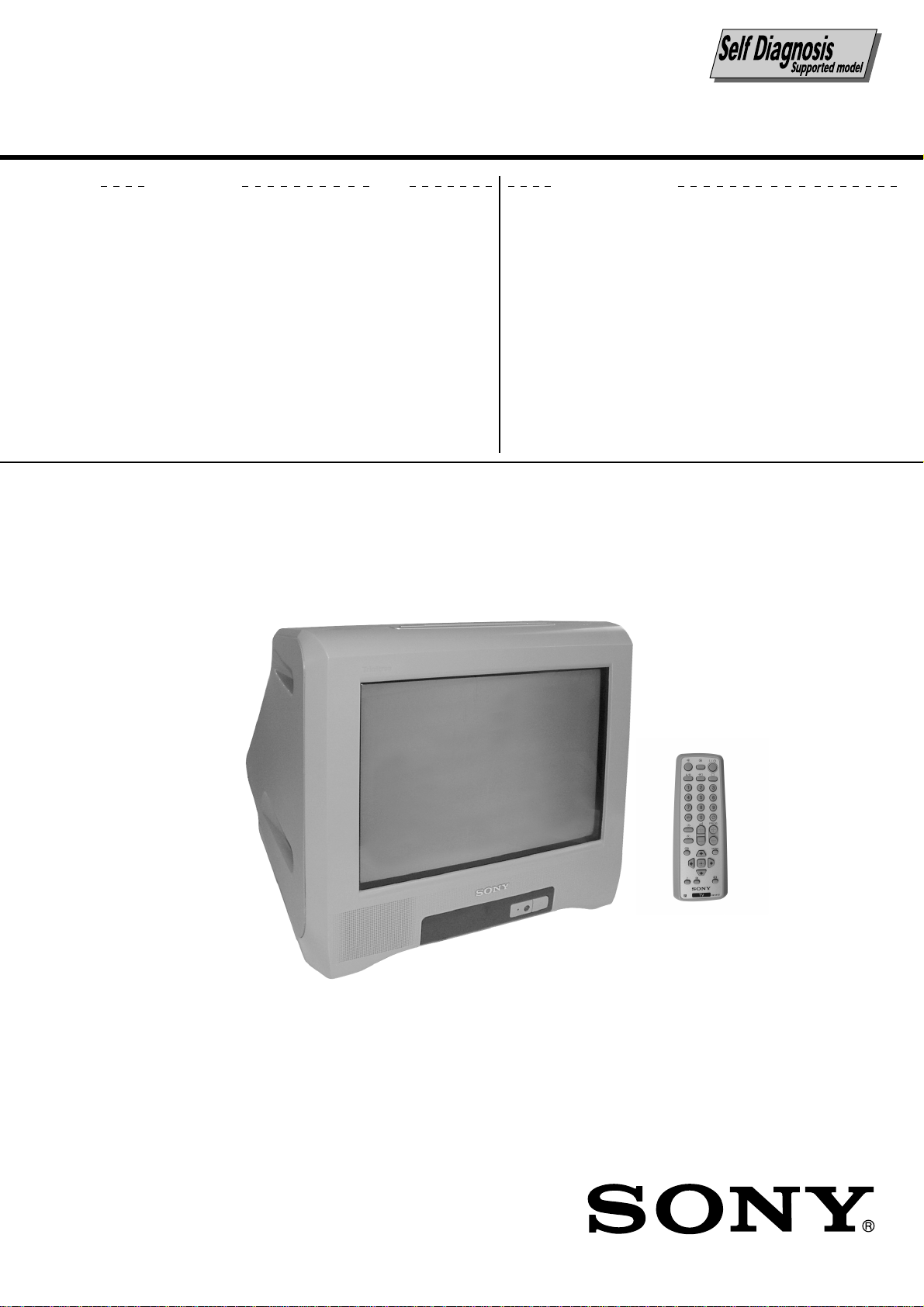
SONY KV-BM14M70, KV-BM14P42, KV-BM14P42/L, KV-BM14P42/V SERVICE MANUAL

REVISION HISTORY
BX1S
CHASSIS
MODEL
KV-BM14M70
KV-BM14P42
KV-BM14P42/L
KV-BM14P42/V
NO. SUFFIX DATE SUPPL. / CORR DESCRIPTION
1 -01 2003/8 -- 1st. Issue
PART NO.: 9-872-363-02
2 -02 2004/4 Supp-1 Service Data Version Change (Page 66)
SERVICE MANUAL
BX1S
CHASSIS
MODEL COMMANDER DEST. CHASSIS NO.
KV-BM14M70 RM-W101 ME SCC-U90G-A KV-BM14P42 RM-W101 Thailand SCC-U94K-A
KV-BM14P42/LRM-W101 Thailand SCC-U94L-A
(BLUE)
KV-BM14P42/VRM-W101 Thailand SCC-U94M-A
(CHAMPAGNE GOLD)
MODEL COMMANDER DEST. CHASSIS NO.
RM-W101
TRINITRON
®
COLOR TV

KV-BM14M70/BM14P42/P42/L/P42/V
RM-W101
SPECIFICATIONS
Note
Power requirements 220-240 V AC, 50/60 Hz KV-BM14P42/BM14P42/L
BM14P42/V
110-240 V AC, 50/60 Hz KV-BM14M70
Power consumption (W) Indicated on the rear of the TV
Television system B/G KV-BM14P42/BM14P42/L
BM14P42/V
B/G, I, D/K, M KV-BM14M70
Color system PAL, PAL 60, NTSC3.58 (AV IN), NTSC4.43 KV-BM14P42/BM14P42/L
BM14P42/V
PAL, PAL 60, SECAM, NTSC3.58, NTSC4.43 KV-BM14M70
Stereo/Bilingual system A2 Bilingual B/G KV-BM14P42/BM14P42/L
BM14P42/V/KV-BM14M70
Channel Coverage
B/G VHF: E2 to E12 / UHF: E21 to E69 KV-BM14P42/BM14P42/L
CATV: S01 to S03, S1 to S41 BM14P42/V
I UHF: B21 to B68 KV-BM14M70
CATV: S01 to S03, S1 to S41
D/K VHF: C1 to C12, R1 to R12 / UHF: C13 to C57, R21 to R60 / KV-BM14M70
CATV: S01 to S03, S1 to S41, Z1 to Z39
M VHF: A2 to A13 / UHF: A14 to A79 / KV-BM14M70
CATV: A-8 to A-2, A to W+4, W+6 to W+84
8 (Antenna) 75-ohm external terminal
Audio output (Speaker) 3W
Number of terminal
D Video Input: 2 Output: 1 Phono jacks; 1 VP-P, 75 ohms
≥ Audio Input: 2 Output: 1 Phono jacks; 500 mVrms
Earphone Output: 1 Monaural minijack
Picture tube 14 in.
Tube size (cm) 37 Measured diagonally
Screen size (cm) 34 Measured diagonally
Dimension (w/h/d, mm) 374 x 355 x 420
Mass (kg) 12
CAUTION
SHORT CIRCUIT THE ANODE OF THE PICTURE TUBE AND
THE ANODE CAP TO THE METAL CHASSIS, CRT SHIELD,
OR CARBON PAINTED ON THE CRT, AFTER REMOVING THE
ANODE.
Design and specifications are subject to change without notice.
SAFETY-RELATED COMPONENT WARNING!!
COMPONENTS IDENTIFIED BY SHADING AND MARK ! ON
THE SCHEMATIC DIAGRAMS, EXPLODED VIEWS AND IN
THE PARTS LIST ARE CRITICAL TO SAFE OPERATION.
REPLACE THESE COMPONENTS WITH SONY PARTS
WHOSE PART NUMBERS APPEAR AS SHOWN IN THIS
MANUAL OR IN SUPPLEMENTS PUBLISHED BY SONY.
– 2 –

TABLE OF CONTENTS
KV-BM14M70/BM14P42/P42/L/P42/V
RM-W101
Section Title Page
SELF DIAGNOSTIC FUNCTION.............................. 4
1. DISASSEMBLY
1-1. Rear Cover Removal ................................................. 7
1-2. Speaker Removal ...................................................... 7
1-3. Chassis Assy Removal .............................................. 7
1-4. Service Position ........................................................ 7
1-5. Terminal Bracket Removal ....................................... 7
1-6. A Board Removal ...................................................... 7
1-7. Picture Tube Removal............................................... 8
2. SET-UP ADJUSTMENTS
2-1. Beam Landing ........................................................... 9
2-2. Convergence............................................................ 10
2-3. Focus Adjustment ................................................... 12
2-4. G2 (SCREEN) Adjustments ................................... 12
2-5 White Balance Adjustment ..................................... 12
2-6 Sub Bright Adjustment ........................................... 12
3. CIRCUIT ADJUSTMENTS
3-1. Adjustment With Commander ................................ 13
3-2. Adjustment Method ................................................ 14
3-3. Picture Quality Adjustments ................................... 28
3-4. Deflection Adjustment ............................................ 28
3-5. Drive Adjustment .................................................... 29
3-6. Picture Distortion Adjustment ................................ 30
Section Title Page
4. DIAGRAMS
4-1. Block Diagram ........................................................ 31
4-2. Circuit Boards Location .......................................... 32
4-3. Schematic Diagram ................................................. 32
4-3-1. A Board — Processer (Block A) ................ 33
4-3-2. A Board — Audio (Block B) ..................... 35
4-3-3. A Board — Power Supply (Block C) ........ 37
4-3-4. A Board — Deflection (Block D) .............. 39
4-3-5. A Board — Tuner (Block E) ...................... 41
4-3-6. A Board — Jack (Block F) ........................ 43
4-3-7. C Board ....................................................... 45
4-4. Voltage Measurement and Waveforms ................... 47
4-5. Printed Wiring Boards and Parts Location ............. 50
4-6. Semiconductors ....................................................... 53
5. EXPLODED VIEWS
5-1. Chassis ..................................................................... 55
6. ELECTRICAL PARTS LIST .................................... 57
OPERATING INSTRUCTIONS
– 3 –

KV-BM14M70/BM14P42/P42/L/P42/V
RM-W101
SELF DIAGNOSTIC FUNCTION
The units in this manual contain a self diagnostic function. If an error occurs, the STANDBY (1) indicator will automatically
begin to flash. A description of the self-diagnosis function is explained in the instruction manual. The number of times the
STANDBY (1) indicator flashes translates to a probable source of the problem. If an error symptom cannot be reproduced,
the remote commander can be used to review the failure occurrence data stored in memory to reveal past problems and
how often these problems occur.
1. DIAGNOSTIC TEST INDICATORS
When an errors occurs, the STANDBY (1) indicator will flash a set number of times to indicate the possible cause of the
problem. If there is more than one error, the indicator will identify the first of the problem areas.
Result for all of the following diagnosis items are displayed on screen. No error has occured if the screen displays a “0”.
Diagnosis
Item
Description
Power does
not turn on
+B overcurrent
(OCP)*
V-Protect
IK (AKB)
Power supply
NG (+5V) for
Video Processor
* If a +B overcurrent is detected, stoppage of the vertical deflection is detected simultaneously. The symptom that is
diagnosed first by the mirco controller is displayed on the screen.
** Refer to Screen (G2) Adjustment in this manual.
No. of timer
STANDBY (1)
indicator flashes
Does not light
2 times
4 times
5 times
8 times
Self-Diagnostic
display/
Diagnosis result
–
2:0
or
2:1 ~ 255
4:0
or
4:1 ~ 255
5:0
or
5:1 ~ 255
8:0
or
8:1 ~ 255
Probable Cause
Location
• Power cord is not plugged
in.
• Fuse is burned out (F600)
A board.
• H OUT (Q805) is shorted.
(A board)
• IC751 is shorted. (C board)
• +13V is not supplied.
(A board)
• IC804 is faulty. (A board)
• Video OUT (IC1545) is
faulty. (A board)
• IC001 is faulty. (A board)
• Screen (G2) is improperly
adjusted.**
• IC604 faulty.
• IC602 faulty.
Detected
Symptoms
• Power does not turn on.
• No power is supplied on
TV.
• AC Power supply is faulty.
• Power does not come on.
• Load on power line is
shorted.
• Has entered standby state
after horizontal raster.
• Vertical deflection pulse is
stopped.
• Power line is shorted or
power supply is shorted.
• No raster is generated.
• CRT Cathode current
detection reference pulse
output is small.
• No power supply to CRT
ANODE.
• No RASTER is generated.
– 4 –
2. DISPLAY OF STANDBY (1) INDICATOR
FLASH COUNT
2 times
4 times
5 times
8 times
Lamp ON 300ms
Lamp OFF 300ms
Lamp OFF 3 sec.
KV-BM14M70/BM14P42/P42/L/P42/V
RM-W101
Diagnostic Item Flash Count*
+B overcurrent 2 times
V-Protect 4 times
IK (AKB) 5 times
Power Supply NG (+5V) 8 times
for Video processor
* One flash count is not used for self-diagnosis.
STANDBY indicator
3. STOPPING THE
STANDBY (1) INDICATOR FLASH
Turn off the power switch on the TV main unit or unplug the power cord from the outlet to stop the STANDBY (1)
indicator from flashing.
4. SELF-DIAGNOSTIC SCREEN DISPLAY
For errors with symptoms such as "power sometimes shuts off" or "screen sometimes goes off" that cannot be confirmed,
it is possible to bring up past occurrences of failure on the screen for confirmation.
[To Bring Up Screen Test]
In standby mode, press buttons on the remote commander sequentially in rapid succession as shown below:
Display
/ Channel 5 / Volume / Power / TV
˘
Note that this differs from entering the service mode (volume [+]).
The following screen will be displayed indicating the error count.
SELF DIAGNOSTIC
2 : 0
3 : N/A
4 : 0
5 : 1
8 : 0
101 : N/A
Numeral "0" means that no fault was detected.
Numeral "1" means the number of a fault occurrence (1 ~ 255).
– 5 –
KV-BM14M70/BM14P42/P42/L/P42/V
RM-W101
5. HANDLING OF SELF-DIAGNOSTIC SCREEN DISPLAY
Since the diagnostic results displayed on the screen are not automatically cleared, always check the self-diagnostic
screen during repairs. When you have completed the repairs, clear the result display to “0”.
Unless the result display is cleared to “0”, the self-diagnosis function will not be able to detect subsequent faults after
completion of the repairs.
[Clearing the result display]
To clear the result display to “0”, press buttons on the remote commander subsequent as shown below when the
self-diagnostic screen is being displayed.
8 , -
[Quitting Self-diagnostic screen]
To quit the entire self-diagnostic screen, turn off the power switch on the remote commander or the main unit.
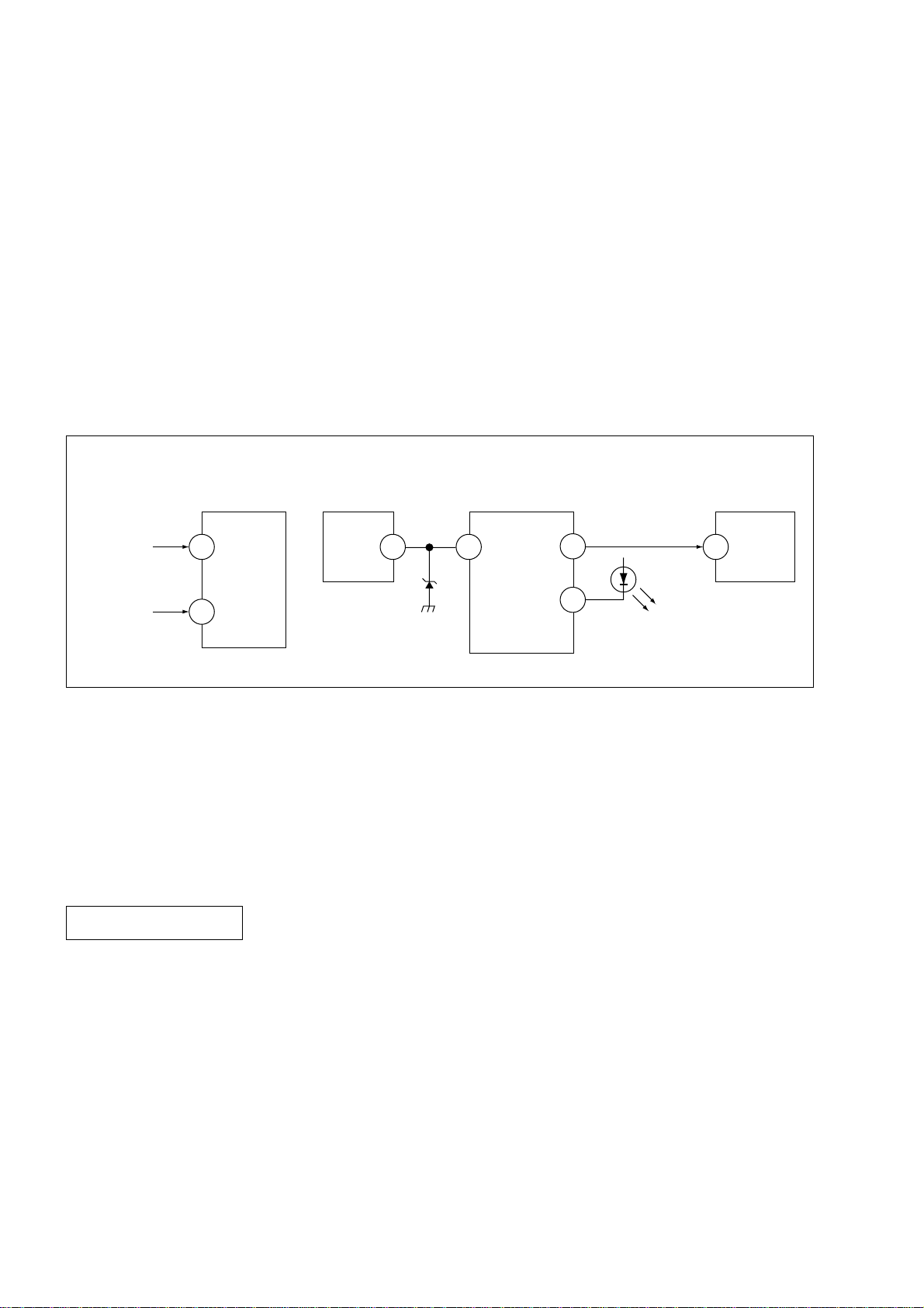
6. SELF-DIAGNOSTIC CIRCUIT
FROM
C BOARD
IC751 PIN 5
A BOARD
FROM
Q804
COLLECTOR
A BOARD
IC001
Y/CHROMA JUNGLE
IK
32
EHTO
A BOARD
IC804
V.OUT
F.B-PLS
A BOARD
IC001
SYSTEM
SDA1
3 1384
V.GUARD
RED LED
99
122
DISPLAY
A BOARD
IC003
MEMORY
5
SDA
[+B overcurrent $OCP%] Occurs when an overcurrent on the +B(135V) line is detected by pin 32 of IC001 (A board).
If the voltage of pin 32 of IC001 (A board) is more than 4V, the unit will automatically go
to standby.
[V-PROTECT] Occurs when an absence of the vertical deflection pulse is detected by pin 13 of IC001
(A board).
[IK $AKB%] If the RGB levels* do not balance within 15 sec after the power is turned on, this error will
be detected by IC001 (A board). TV will stay on, but there will be 5 times LED blinking.
POWER SUPPLY NG (+5V)
for VIDEO PROCESSOR
Occurs when IC001 internal HV protect detects an abnormal H-Pulse (frequency) due to
improper power supply to IC001. TV cuts off high voltage power of anode CRT. No picture
will be detected. eg: IC602, IC604 go faulty.
* (Refers to the RGB levels of the AKB detection Ref pulse that detects IK.)
– 6 –
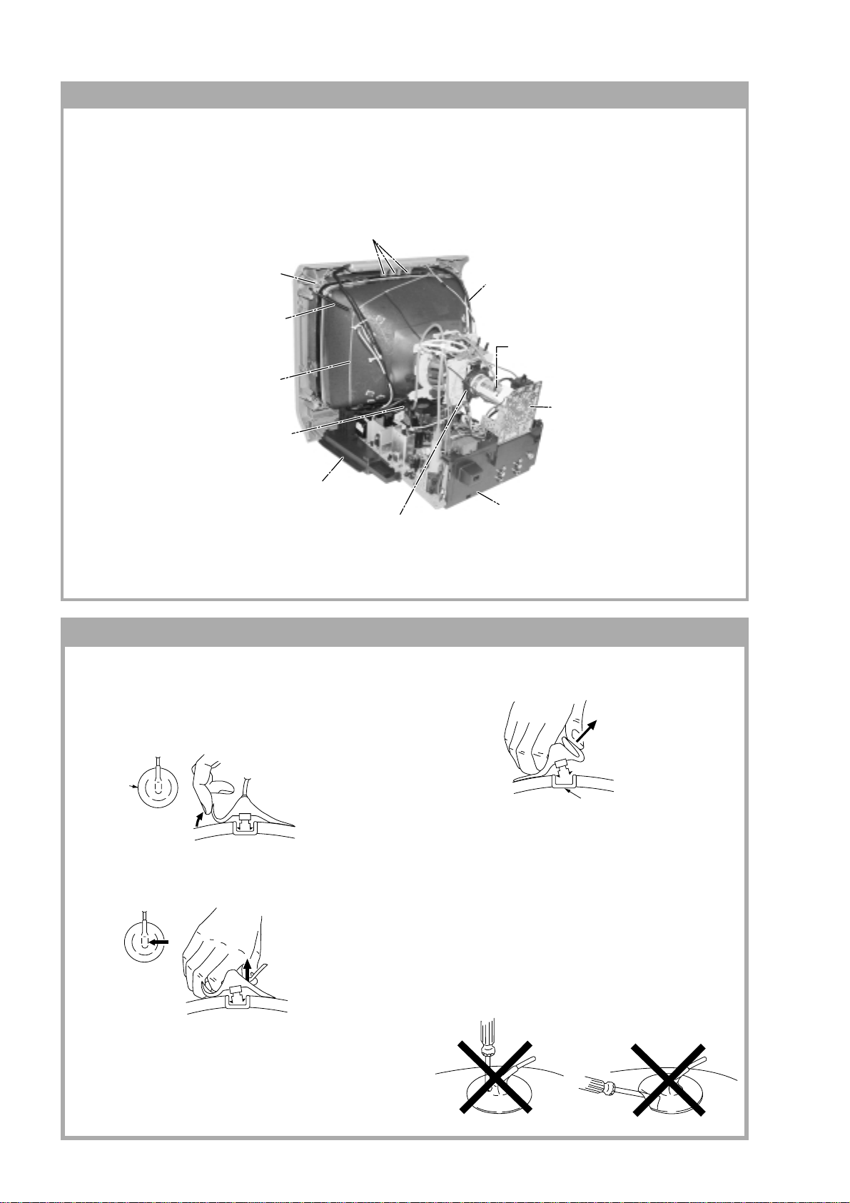
SECTION 1
DISASSEMBLY
KV-BM14M70/BM14P42/P42/L/P42/V
RM-W101
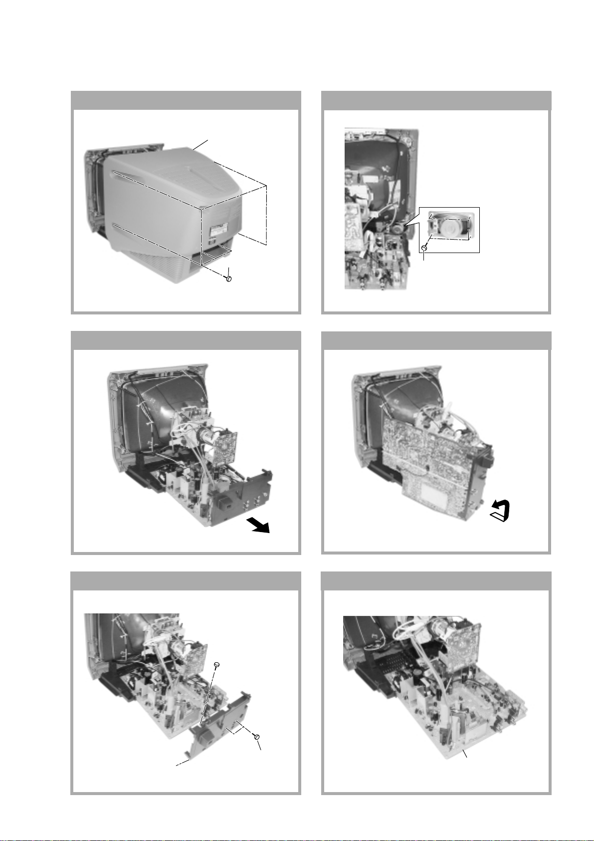
1-1. REAR COVER REMOVAL
1 Rear cover
2 Six screws
(+BVTP 4 × 16)
1-3. CHASSIS ASSY REMOVAL
1-2. SPEAKER REMOVAL
1 Four screw
(+BVTP 4 × 16)
1-4. SERVICE POSITION
1-5. TERMINAL BRACKET REMOVAL 1-6. A BOARD REMOVAL
3 One screw
(+BVTP 3 × 12)
1 Terminal
bracket
2 Two screw
(+BVTP 4 × 16)
– 7 –
1 A board
KV-BM14M70/BM14P42/P42/L/P42/V
c
RM-W101
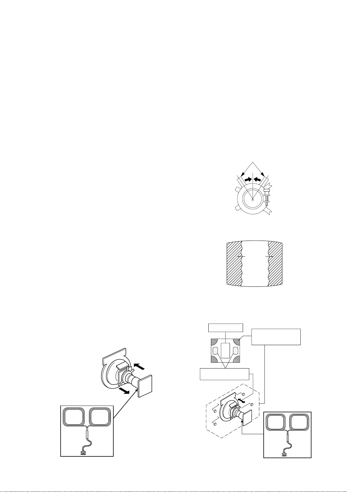
1-7. PICTURE TUBE REMOVAL
Note:
• Please make sure the TV set is not in standing position before removing necessary CRT support located on bottom
right and left.
1) Place the TV set with the CRT face down on a cushion jig.
2) Remove the rear cover.
3) Unplug all inder connecting leads from the Deflection Yoke, Degaussing Coil and CRT grounding strap.
qf Block Center
qd Nut, Special, CRT (4)
qa Spring Tension Removal
0 Earth Coating Assy
4 Anode Cap Removal
9 Support, CRT(2) Removal
7 Loosen the Deflection Yoke
fixing screw and remove
qs Band, DGC Removal
6 Loosen the Neck Assembly
fixing screw and remove
5 C Board Removal
8 Chassis Assy Removal
• REMOVAL OF ANODE-CAP
Note:
• After removing the anode, short circuit the anode of the picture tube and the anode cap to the metal chassis, CRT
shield or carbon paint on the CRT.
• REMOVING PROCEDURES
a
a
1 Turn up one side of the rubber cap in the direction
indicated by the arrow A.
b
b
2 Using a thumb pull up the rubber cap firmly in the di-
rection indicated by the arrow B.
3 When one side of the rubber cap is separated from
the anode button, the anode-cap can be removed by
anode button
turning up the rubber cap and pulling it up in the
direction of the arrow C.
• HOW TO HANDLE AN ANODE-CAP
1 Do not damage the surface of anode-caps with
sharp shaped objects.
2 Do not press the rubber too hard so as not to
damage the inside of anode-cap.
A metal fitting called the shatter-hook terminal is
built into the rubber.
3 Do not turn the foot of rubber over too hard.
The shatter-hook terminal will stick out or damage
the rubber.
– 8 –
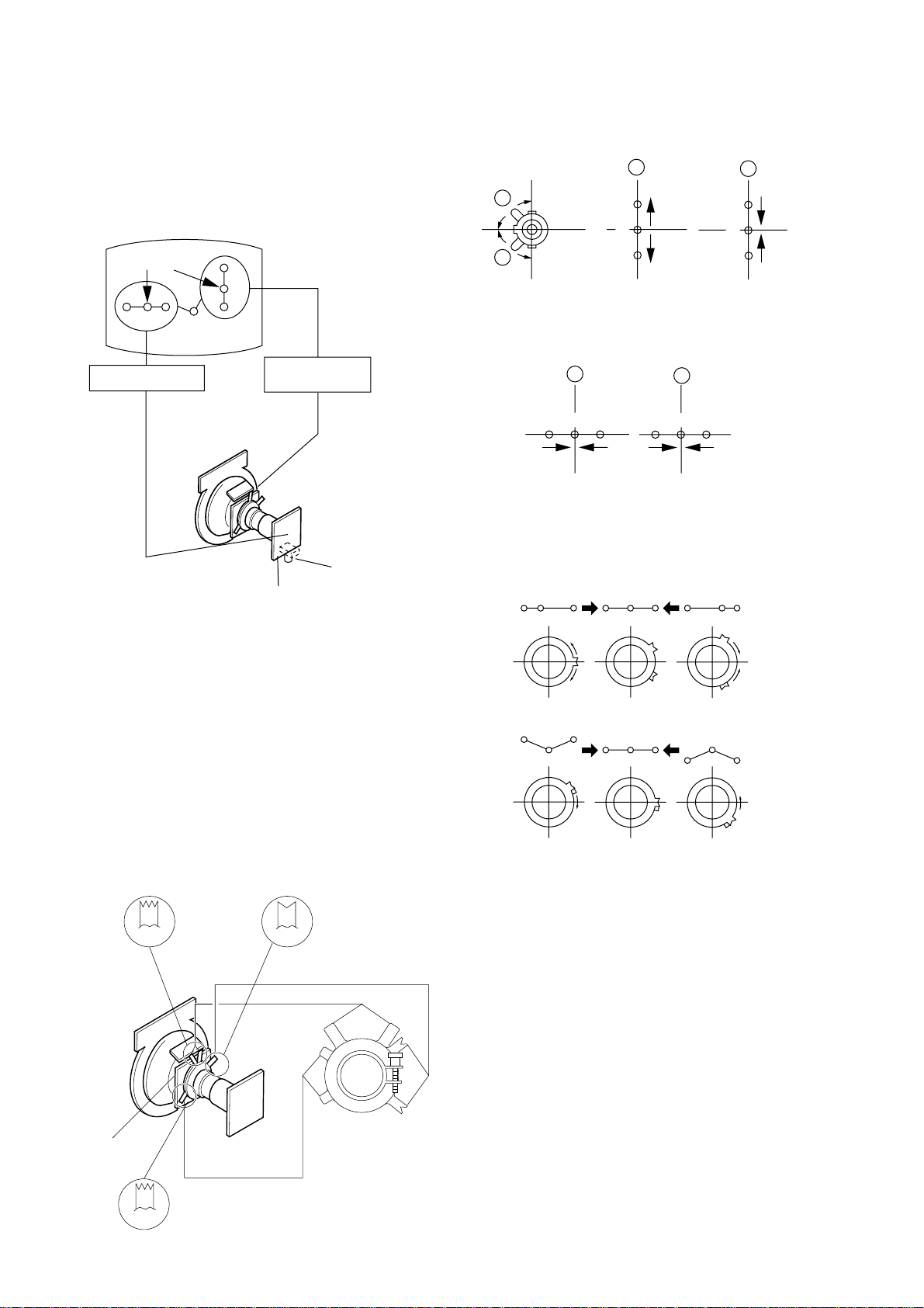
SECTION 2
Purity control
SET-UP ADJUSTMENTS
KV-BM14M70/BM14P42/P42/L/P42/V
RM-W101
• The following adjustments should be made when a
complete realignment is required or a new picture
tube is installed.
Perform the adjustments in the following order :
1. Beam Landing
2. Convergence
3. Focus
Set the controls as follows unless otherwise noted:
VIDEO model ..................................................... Standard
PICTURE control .................................................. normal
BRIGHTNESS control .......................................... normal
4. Screen(G2)
5. White Balance
Note : Test Equipment Required.
1. Pattern Generator
2. Degausser
3. DC Power Supply
4. Digital Multimeter
5. Oscilloscope
......................................................................................................................................................................................................................
Preparation :
• In order to reduce the influence of geomagnetism on
the set's picture tube, face it east or west.
• Switch on the set's power and degauss with the
degausser.
2-1. BEAM LANDING
Picture Mode: DYNAMIC
1. Input a white signal with the pattern generator.
Contrast
Brightness
}
normal
2. Set the pattern generator raster signal to a green
raster.
3. Move the deflection yoke to the rear and adjust with
purity control so that the green is at the center and
the blue and the red take up equally sized areas on
each side. (See Figures 2-1 through 2-4.)
4. Move the deflection yoke forward and adjust so that
the entire screen is green. (See Figure 2-1.)
5. Switch the raster signal to blue then to red and verify
the condition.
6. When the position of the deflection yoke has been
decided fasten the deflection yoke with the screws
and DY spacers.
7. If the beam does not land correctly in all the corners,
use a magnet to adjust it. (See Figure 2-4.)
Purity control
corrects this area.
b
Fig. 2-2
Blue
Red
Green
Fig. 2-3
Disk magnets or rotatable
disk magnets correct these
a
areas (a-d).
d
c
Deflection yoke positioning
corrects these areas.
b
c
a
d
Fig. 2-1 Fig. 2-4
– 9 –
KV-BM14M70/BM14P42/P42/L/P42/V
RM-W101
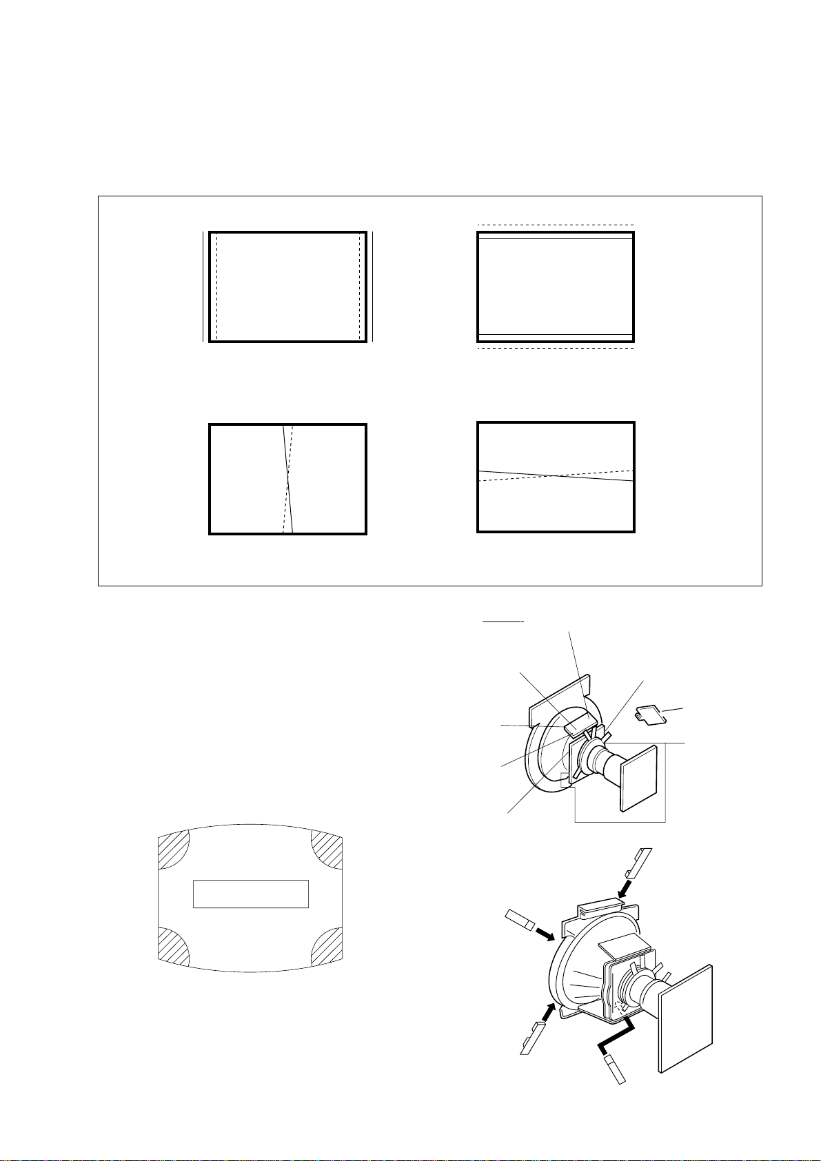
2-2. CONVERGENCE
• Before starting this adjustment, adjust the focus,
horizontal size and vertical size.
• Receive dot/hatch signal.
• Pic mode: Soft.
(1) Horizontal and Vertical Static Convergence
Center dot
R G B
H. STAT VR
R
G
B
V. STAT
Magnet
RV750
H. STAT
C Board
Operation of V.STAT magnet
If the V.Stat magnet is moved in the “A” and “B” arrows,
the red, green and blue dots moves as shown below.
A
B
A
B
G
R
B
B
G
R
Moved RV750 H.STAT.
the red, green and blue dots move as shown below.
A
RGGBB
B
R
4. BMC (Hexapole) Magnet.
If the red, green and blue dots are not balanced or
aligned, then use the BMC magnet to adjust in the
manner described below.
RG B R G B R GB
1. (Moving vertically), adjust the V.STAT magnet so that
the red, green and blue dots are on top of each other
at the center of the screen.
2. (Moving horizontally), adjust the H.STAT control so
that the red, green and blue dots are on top of each
other at the center of the screen.
3. If the H.STAT variable resistor cannot bring the red,
green and blue dots together at the center of the
screen, adjust the horizontal convergence with the
H.STAT variable resistor and the V.STAT magnet in
the manner given below.
(In this case, the H.STAT variable resistor and the
V.STAT magnet influence each other, so be sure to
perform adjustments while tracking.)
BMCPurity
BMC (Hexapole)
Purity
RB
G
RG
GB
RB
DY pocket
V.STAT
V.STAT
– 10 –
(2) Convergence Rough Adjustment
Preparation:
• Before starting this adjustment, adjust the horizontal
static convergence and the vertical static
convergence
B
R
KV-BM14M70/BM14P42/P42/L/P42/V
RM-W101
B
R
TLH
RB
YCH
TLH Insert TLH Correction Plate to DY Pocket
(Left or Right)
YCH Insert YCH VOL on DY
TLV Rotate TLV VOL on DY
XCV Rotate XCV Adj core on DY
(3) Screen corner Convergence
1. Affix a Piece A (90), conv. correct corresponding to
the misconverged areas.
R
B
ON DY:
TLV
XCV
YCH
TLV
XCV
TLV
DY pocket
TLH Plate
XCV
ba
a-d : screen-corner
misconvergence
cd
– 11 –
DY pocket
a
d
Piece A (90), conv. correct
b
c
KV-BM14M70/BM14P42/P42/L/P42/V
RM-W101
2-3. FOCUS ADJUSTMENT
FOCUS adjustment should be completed before the W/B
adjustment:
1. Receive digital monoscope pattern.
2. Set picture mode: DYNAMIC.
3. Adjust focus VR to obtain a just focus at the center of
the screen.
4. Change receiving signal to white pattern and blue
back.
5. Confirm MAGENTA RING is not noticeable. Incase
magenta ring is obvious, then adjust FOCUS VR to
balance magenta ring and FOCUS.
FOCUS
2-5. WHITE BALANCE ADJUSTMENT
1. Set to Service Mode (Refer Section 3-1:
ADJUSTMENTS WITH COMMANDER)
2. Input white raster signal.
3. Set Picture to <DYNAMIC mode>
4. Select RDRV (02) with 1 and 4 and fixed the value
to 25 with 3 and 6
5. Adjust WHBL GDRV (03) and BDRV (04) with 1 and
4 and adjust the data with 3 and 6 for best white
balance in Highlight condition.
6. Write into the memory by pressing [MUTING] then -.
7. Adjust WHBL BKOR (00) and BKOG (01) with 1 and
4 and adjust the level with 3 and 6 for best white
balance cut-off condition.
8. Write into memory by pressing [MUTING] then -.
2-6. SUB BRIGHT ADJUSTMENT
1. Set to service mode.
2. Brightness set to 50%, Picture....Minimum
3. Select WHBL SBRT (10) with 1 and 4 and adjust
SBRT (10) data with 3 and 6 so that the third
stripe from right dimly lit.
4. Write into the memory by pressing [MUTING] then -.
5. GA models Cut Off : 10 IRE
Slightly Glimmer : 20 IRE
SCREEN
FLYBACK TRANSFORMER (T802-14")
FLYBACK TRANSFORMER (T801-21")
2-4. G2 (SCREEN) ADJUSTMENTS
1. Set the PICTURE & BRIGHTNESS to STANDARD.
2. Put the Video input mode signal.
3. Connect R,G,B of the C board cathode to
oscilloscope.
4. Adjust Brightness to obtain the cathode value to
value below.
5. Adjust G2 (screen) on the FBT until picture shows
the point before cut off.
165 ± 2VDC
– 12 –

KV-BM14M70/BM14P42/P42/L/P42/V
SECTION 3
CIRCUIT ADJUSTMENTS
3-1. ADJUSTMENTS WITH COMMANDER
Service adjustments to this model can be performed using the supplied remote commander RM-W101.
a. ENTERING SERVICE MODE
With the unit on standby
t [DISPLAY] t 5 t [VOL $+% ] t [POWER]
This operation sequence puts the unit into service mode.
This screen display is:
RM-W101
category in decimal item name in decimal NG service command frequency video input name
GEOM 006 HSIZ 031 x SERVICE 60 S VIDEO 1
release ID version in binary for factory color system (decimal?)
SUS01 0.69U 0001 1111 FF FF NTSC3 65535
111 11 11 1 7 11 FG xy 111 000000 000000
S : for Sony
A : Aiwa
U S : US/Latin/Taiwan
E U : Europe
G A : General Area
J P : Japan
item no. service data NVM field channel no./
software service data reserved power on time
Status Byte Status Byte
Flash DCXO #1 SSD #2 SSD
VDSP_C Flag
CO_LOCKED
VDSP
Detected Stereo Type (Direct Value from CZ_ Stereo_Mode)
111 Needed for Nicam DCXO aligment Purpose
xy Value of x = 0 - Unknown, 1 - BTSC, 2 - A2, 3 - NICAM,
4 - KOREAN, 5 - Japan, 6 - AV Stereo
Value of y = 0 - Mono, 1 - Stereo, 2 - Bilingual, 4 - SAP/Single
0 1 : serial no. of the M/P release
for each destination
b. METHOD OF CANCELLATION FROM SERVICE MODE
Set the standby condition (Press [POWER] button on the commander), then press [POWER] button again, hereupon it
becomes TV mode.
c. METHOD OF WRITE INTO MEMORY
1. Set to Service Mode.
2. Press 1 (UP) and 4 (DOWN), to select the adjustment item.
3. Change item by pressing 3, 6.
4. Press [MUTING] button to indicate WRITE on the screen.
5. Press - button to write into memory.
1, 4 Select the adjustment item.
r
3, 6 Raise/lower the data value.
r
[MUTING] Writes.
r
- Executes the writing.
d. MEMORY WRITE CONFIRMATION METHOD
1. After adjustment, pull out the plug from AC outlet, and then plug into AC outlet again.
2. Turn the power switch ON and set to Service Mode.
3. Call the adjusted items again to confirm adjustments were made.
– 13 –
KV-BM14M70/BM14P42/P42/L/P42/V
RM-W101
e. OTHER FUNCTION VIA REMOTE COMMANDER
7, - All the data becomes the values in memory.
8, - All user control goes to the standard state.
Display, - Service data initialization (Be sure not to use usually.)
2, 5 Select Device or Category
3-2. ADJUSTMENT METHOD
Item Number 000 HPOS
This explanation uses H POSITION as an example.
1. Select "000 HPOS" with the 1 and 4 buttons, or 2 and 5.
2. Raise/lower the data with the 3 and 6 buttons.
3. Select the optimum state. (The standard is IF for PAL reception.)
4. Write with the [MUTING] button. (The display changes to WRITE.)
5. Execute the writing with the - button. (The WRITE display will be changed to red color while excuting, and back to
SERVICE.)
Example on screen display :-
GREEN
GEOM 000 HPOS 039 SERVICE 50 VIDEO 1
Adjusted with [3] and [6] buttons.
GREEN
GEOM 000 HPOS 039 WRITE 50 VIDEO 1
write with [MUTING].
RED
GEOM 000 HPOS 039 WRITE 50 VIDEO 1
Write executed with [0].
The WRITE display
then returns to green
SERVICE
Use the same method for all Items. Use 1 and 4 to select the adjustment item, use 3 and 6 to adjust, write with
[MUTING], then execute the write with -.
Note : 1. In [WRITE], the data for all items are written into memory together.
2. For adjustment items that have different standard data between 50Hz or 60Hz, be sure to use the respective
input signal after adjustment.
– 14 –
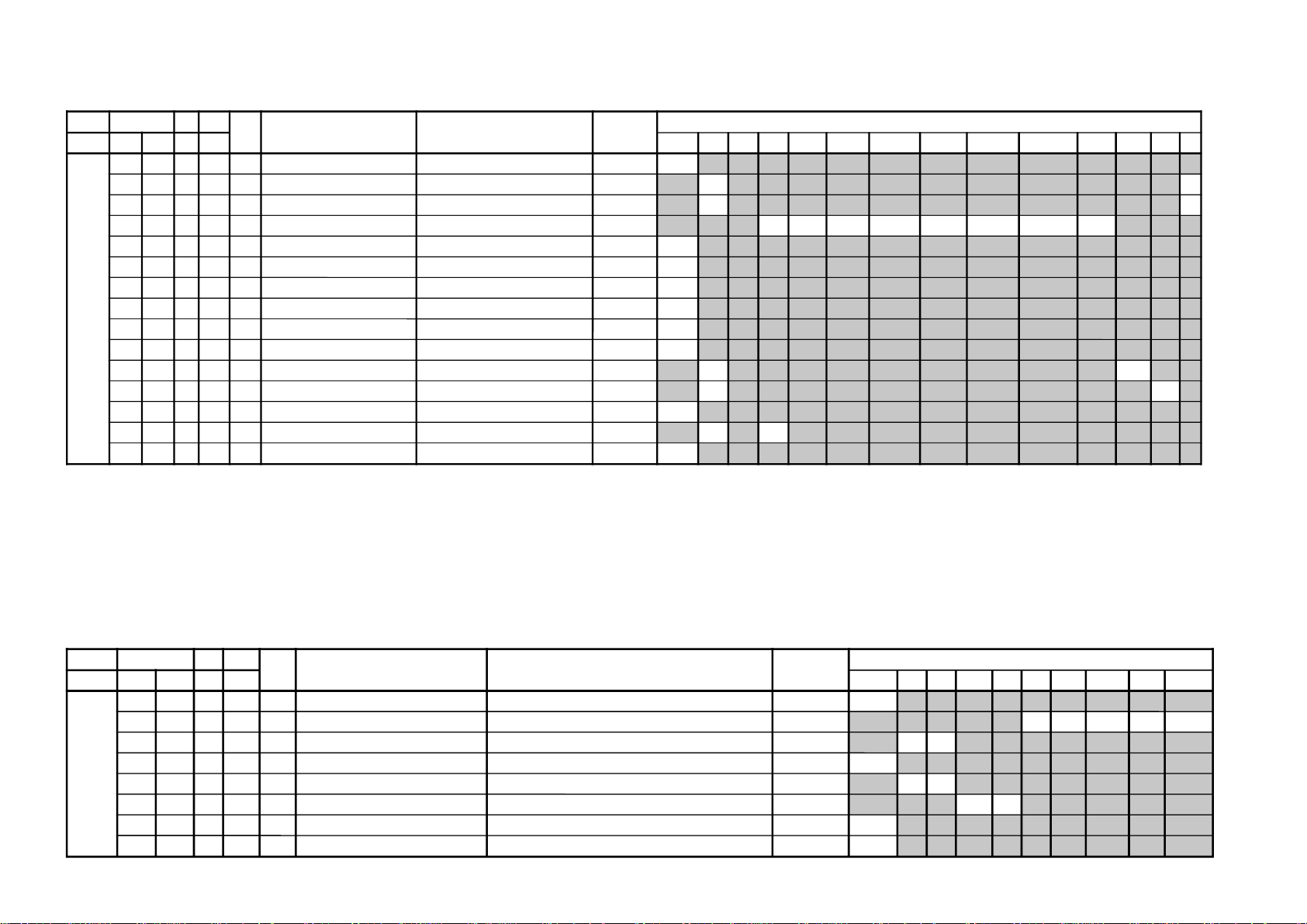
Adjustment Item Table
JVTytilanoitcnuF.tinIegnaRATADnoitcnuFetoN&elbaTemaNeciveD)deliateD(eulaVlaitinI/sserddAMVN
yrogetaC.oNemaNceDceD )sserddAevalS(nommoC050605w06w
MOEG000SOPH130360TSUJDA)SH(tfihSlatnoziroH )BGRNPJ+(06w/05w/06/05rossecorP-VT
24242424
100RAPH130360TSUJDAmargolellaraPlatnoziroH06w/05w/06/05)hA8(
13131313
200WOBH130360TSUJDAwoBlatnoziroH06w/05w/06/05
13131313
300NILV130360TSUJDAytiraeniLlacitreV06w/05w/06/05
13131313
400RCSV130360TSUJDAllorcSlacitreV06w/05w/06/05
13131313
500ZISH130360TSUJDA)WE(htdiWWE06w/05w/06/05
52525252
600WPWE130360TSUJDA)WP(htdiW/alobaraPWE )BGRNPJ+(06w/05w/06/05
13131313
700POCU710360TSUJDAalobaraPrenroCreppUWE06w/05w/06/05
13131313
800POCL710360TSUJDAalobaraPrenroCrewoLWE06w/05w/06/05
13131313
900ZTWE130360TSUJDAmuizeparTWE06w/05w/06/05
13131313
010PLSV130360TSUJDA)SV(epolSlacitreV06w/05w/06/05
13131313
110ZISV510360TSUJDAedutilpmAlacitreV06w/05w/06/05
51515151
210ROCS410360TSUJDA)CS(noitcerroC-S06w/05w/06/05
52525252
310SOPV130360TSUJDA)HSV(tfihSlacitreV06w/05w/06/05
13131313
410LBH000100XIFedoMgniknalBBGR06w/05w/06/05
10101010
510FBW700510XIF)FBW(gniknalBediWfognimiT06w/05w/06/05
70707070
610RBW700510XIF)RBW(gniknalBediWfognimiT06w/05w/06/05
01010101
710LBS000100XIFgniknalBecivreSenon00
810YPOC000100XIFaeraMVNzH06/05llaotatadOEGehtypoCenon00
– 15 –
KV-BM14M70/BM14P42/P42/L/P42/V
RM-W101
– 16 –
JVTytilanoitcnuF.tinIegnaRATADnoitcnuFetoN&elbaTemaNeciveD )deliateD(eulaVlaitinI/sserddAMVN
yrogetaC.oNemaNceDceD
)sserddAevalS(nommoCpmeTloC
)rehtoHGIH(
pmeTloC
)rehtoWOL(
pmeTloC
)rehtoMRON(
pmeTloC
)VUYHGIH(
pmeTloC
)VUYWOL(
pmeTloC
)VUYLAMRON(
pmeTloC
)BGRHGIH(
pmeTloC
)BGRWOL(
pmeTloC
)BGRMRON(
srehtOBGRVUYedomciP
0
edomciP
1
edomciP
2
edomciP
3
LBHW000ROKB130360TSUJDARtesffOleveLkcalB )srehtO/BGR/VU(*)lamroN/WOL/HGIH(pmetlocrossecorP-VT
131313131313131313
100GOKB130360TSUJDAGtesffOleveLkcalB )srehtO/BGR/VU(*)lamroN/WOL/HGIH(pmetloc)hA8(
131313131313131313
200VRDR730360XIFRtnioPetihW )srehtO/BGR/VU(*)lamroN/WOL/HGIH(pmetloc)HA8(orP-VT
737373737373737373
300VRDG730360TSUJDAGtnioPetihW )srehtO/BGR/VU(*)lamroN/WOL/HGIH(pmetloc
131313131313131313
400VRDB730360TSUJDABtnioPetihW )srehtO/BGR/VU(*)lamroN/WOL/HGIH(pmetloc
131313131313131313
500GPL000100XIFteserPniaGBGR enon10
600RGP130721XIF)RGP(RniaGteserP enon
**
700GGP130721XIF)GGP(GniaGteserP enon
**
800BGP130721XIF)BGP(BniaGteserP enon
**
900FONG000510XIFtesffOniaGteserP enonpoolCCC51
010TRBS130360TSUJDAssenthgirB-buS VUY/BGR/srehtO
131313
110ORBS000300XIF)ciPtnegilletnI(tesffOssenthgirB-buS enon00
210LGE000100XIFmetsySCCCnipooLniaGelbanE enon10
310LGS000300XIFmetsySCCCnitnerruChgiHfonoitceleS enon00
410BKA000100XIFnoitazilibatStnerruCkcalB enon00
510SBC000100XIFgnitimiLtnerruCmaeBfoecneuqeSlortnoC enon00
610BBGR000300XIFgniknalBBGR enon00
710GBLB000100XIFtuptuOneerG&eulBfogniknalB enon00
810BFO000100XIFeulBtesffOleveLkcalB enon10
910RBSN000510XIFtesffOssenthgirBdradnatSnoN enon50
020PBW000300XIF)woL:3,2,lamroN:1,hgiH:0(gnitteSpmeTroloC edoMerutciP
00102010
JVTytilanoitcnuF
.tinIegnaRATADnoitcnuFetoN&elbaTemaNeciveD )deliateD(eulaVlaitinI/sserddAMVN
yrogetaC.oNemaNceDceD
)sserddAevalS(nommoCVUYlap05
)VT(
lap05
)oediV(
maces05
)VT(
maces05
)oediV(
VT06oediV06VUY05VUY06BGR05BGR06edomciP
0
edomciP
1
edomciP
2
edomciP
3
ocE*cimanyD
)npJ(dts
ocE*cimanyD
)npJ(hcum
ocE*dradnatS
)npJ(dts
ocE*dradnatS
)npJ(hcum
dtsocE
)npJ(
hcumocE
)npJ(
VToediVVT
ediW
oediV
ediW
MVA
)npJ(
ediWVA
)npJ(
JDAS000XAMP360360TSUJDAmumixaMerutciP )BGRNPJ+(>ediW/lamroN</)ediW/lamroN(*)oediV/VT( rossecorP-VT
737373737373
100EUHS700510TSUJDAeuH-buS oediV/VT
7070
200PHSS510360XIFssenprahS-buS )BGRNPJ+(VUY/oediV/VT
**
****
300OHSS000300XIF)ciPtnegilletnI(tesffOssenprahS-buS enon20
400LOCS130360TSUJDAroloC-buS /)oediv(maces05/)vt(maces05/)oediv(lap05/)vt(lap05
BGR06/BGR05/VUY06/VUY05/oediv06/VT06
13131313131313131313
500OOCS000300XIF)ciPtnegilletnI(tesffOroloC-buS enon20
600CIP130721XIF
;)dilavni(001>,)dilav(001-0:AG[lortnoCerutciP
])dilavni(6tiberongi;)dilav(36-0:srehtO
)ataDteseRresU=lanosreP:AG(ledoMerutciP
0010856001
700LOC130721XIF
;)dilavni(001>,)dilav(001-0:AG[lortnoCroloC
])dilavni(6tiberongi;)dilav(36-0:srehtO
)ataDteseRresU=lanosreP:AG(ledoMerutciP
65050405
800TRB130721XIF
,)dilav(001-0:AG[lortnoCssenthgirB
tiberongi;)dilav(36-0:srehtO;)dilavni(001>
])dilavni(6
)ataDteseRresU=lanosreP:AG(ledoMerutciP
05050605
900EUH130721XIF
;)dilavni(001>,)dilav(001-0:AG[lortnoCeuH
])dilavni(6tiberongi;)dilav(36-0:srehtO
)ataDteseRresU=lanosreP:AG(ledoMerutciP
05050505
010PHS130721XIF
,)dilav(001-0:AG[lortnoCssenprahS
tiberongi;)dilav(36-0:srehtO;)dilavni(001>
])dilavni(6
)ataDteseRresU=lanosreP:AG(ledoMerutciP
06050505
110OCEP200300XIF
edomevasrewopniataderutciP
)ylnoNAPAJrofdilav(
)hcumocE/dtsocE(*edoMerutciP
00000000
210VLRP200300XIF
edomevasrewopfotneiciffeoC
)ylnoNAPAJrofdilav(
hcumocE/dtsocE
0000
NOTE
• Column with (**) please refer page 24.
KV-BM14M70/BM14P42/P42/L/P42/V
RM-W101
NOTE
• Column with (**) please refer page 24.
– 17 –
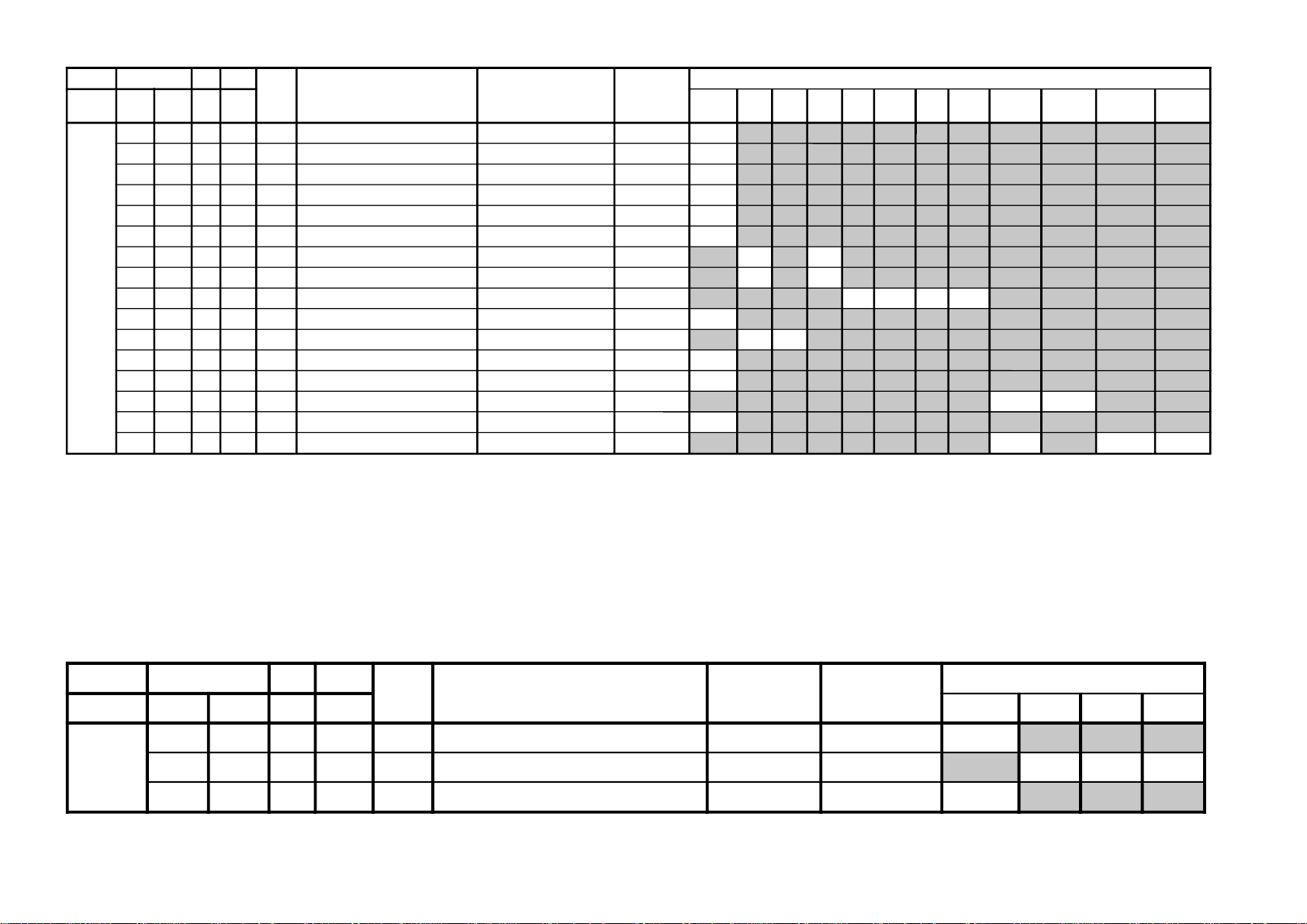
JVTytilanoitcnuF.tinIegnaRATADnoitcnuFetoN&elbaTemaNeciveD )deliateD(eulaVlaitinI/sserddAMVN
yrogetaC.oNemaNceDceD )sserddAevalS(nommoCsrehtOBGRVUY)VT(LAP)VT(CSTN)VT(MACES)oediV(LAP)oediV(CSTN)oediV(MACESTUPNI-SMACESCSTNVT
CY000QRFP000300XIFyaleDdnaycneuqerFretneCgnikaeP rossecorP-VT
**
100APR####300XIFtoohSrevO&erPoitaR rehto/VT
20
20
200OPR200300XIFskaePevitageN&evitisoPfooitaR rehto/VT
20
20
300YLDY210510XIFyaleD-Y TUPNI-S/VUY+)OEDIV/VT(*)MACES/CSTN/LAP(
****************
400TAMC000300XIFxirtaM)ASU/napaJ(CSTNroMACES-LAP )BGRNPJ(00
500LCA100100XIFgnitimiLroloCcitamotuA 10
600BC000100XIFycneuqerFretneCssapdnaBamorhC )xif0:oediV*(VThtiwylnodilav10
700OBS100300XIFtesffOkcalBMACES 00
800ESHC100300XIFytivitisneStnedICSTN/LAP 20
900OLC000100XIFretliF)lleB(ehcolCfoycneuqerFretneC 00
010PRTC000100XIFedoMparTamorhC srehto/MACES
00
10
110SPB000100XIFeniLyaleDdnab-esaBamorhCfossapyB srehto/CSTN
**
**
210OCF000100XIFnOroloCdecroF 00
310TNIT130360XIFlortnoCtniTdnaB-esaB srehto/VUY
13
13
410VUT000100XIFslangiSVUnolortnoCtniT 00
JVTytilanoitcnuF.tinIegnaRATADnoitcnuFetoN&elbaTemaNeciveD )deliateD(eulaVlaitinI/sserddAMVN
yrogetaC.oNemaNceDceD )sserddAevalS(nommoC0506srehtoVUYVToediVtxeteleTpi-VTlangisoN
CNYS000SYS000100XIFtupnICNYSYnonoitazinorhcnyS 00
100OF000300XIFtnatsnoCemiT1esahP )FR(langisoNrogninuTotuA/txeteleT/oediV/FFOPIVT/NOPIVT
3030100000
200DIV000100XIFedoMtnedIoediV 06/05
0000
300LSF000100XIFcnySlacitreVrofleveLgnicilSdecroF 00
400LSS000100XIFrotarapeScnySleveLgnicilS 06/05
0000
500DIVS100700XIFnoitacifitnedIoediVrofnoitceleSecruoS srehtO/VUY
0070
600FROF000300XIFycneuqerFdleiFdecroF 30
700KVM000100XIFgniyeKnoisiVorcaM 10
NOTE
• Column with (**) please refer page 24.
KV-BM14M70/BM14P42/P42/L/P42/V
RM-W101
KV-BM14M70/BM14P42/P42/L/P42/V
JVTytilanoitcnuF.tinIegnaRATADnoitcnuFetoN&elbaTemaNeciveD)deliateD(eulaVlaitinI/sserddAMVN
yrogetaC.oNemaNceDceD )sserddAevalS(nommoCVUYVToediV
WS0002VC000100XIFnoitceleSlangiStupnI2SBVC 00
100OVS100300XIF84@niPISBVC/OVS/OVFIfonoitcnuFVUY/oediV/VT
201010
200LFD000100XIFnoitcetorPhsalF 00
JVTytilanoitcnuF.tinIegnaRATADnoitcnuFetoN&elbaTemaNeciveD )deliateD(eulaVlaitinI/sserddAMVN
yrogetaC.oNemaNceDceD
)sserddAevalS(nommoCsrehtOBGReviLVT
)nyD(
VT
)srehtO(
oediV
)nyD(
oediV
)srehtO(
pmeTroloC
)HGIH(
pmeTroloC
)srehtO(
roloC
)WOL(pmeT
pmeTroloC
)LAMRON(
TCIP000LDAC700510XIFleveLevirDedohtaC 00
100AFC000300XIFedoMretliFbmoC
**
200COS200300XIFleveLgnippilCtfoS )hA8(00
300LWP100100XIFhctiwSgnitimiLetihWkaeP 10
400LTHW600510XIFgnitimiLetihWkaeP 00
500MAG100100XIFammaG 00
600STW100300XIFhctertSetihWdnalortnoCammaGsrehtO/eviL
10
10
700RFT000100XIFlangiSecnanimuLfooitaRrefsnarTCD )BGRNPJ+(srehtO/eviL
10
10
800ROC300300XIFgniroC )srehto/anyD(*)oediV/VT(
00000000
900OROC000100XIF)ciPtnegilletnI(tesffOgniroC 00
010SKB300300XIFhctertSkcalBsrehto/BGR
2020
110SAA100100XIFhctertSkcalBehtffohctiwSotaerAkcalB 00
210KSD000100XIFlortnoCnikScimanyD 00
310SLB000100XIFhctertSeulB )SREHTO/HGIH(pmetloc
0000
410SLBN000100XIFtiucriChctertSeulBnoitarepO 00
510RRN000100XIFnoitcudeRdeRnoN )LAMRON/WOL/HGIH(pmetloc
10
1010
RM-W101
– 18 –
NOTE
• Column with (**) please refer page 24.
– 19 –
JVTytilanoitcnuF.tinIegnaRATADnoitcnuFetoN&elbaTemaNeciveDnommoC
yrogetaC.oNemaNceDceD )sserddAevalS(
FIV000DFIO630360XIFrotaludomeDFItesffO rossecorP-VT63
100TCGA130360XIFrevo-ekaTCGA )hA8(13
200MTS000100XIFedoMgninuThcraeS 10
300DG000100XIFlangiS1SBVCnoyaleDpuorG 00
400SCGA100300XIFdeepSCGAFI 10
500IFF000100XIFLLPFIretliFtsaF 00
600PMAO300300XIF)metsyS'L&Lylno(edutilpmAlangiStuptuOoediV 30
700IAV000100XIF)metsyS'L&Lylno(noitcerroCedutilpmAlangiStuptuOImetsyS 00
JVTytilanoitcnuF.tinIegnaRATADnoitcnuFetoN&elbaTemaNeciveD)deliateD(eulaVlaitinI/sserddAMVN
yrogetaC.oNemaNceDceD
)sserddAevalS(nommoCedomciP
0
edomciP
1
edomviP
2
edomciP
3
MV000DBGR300700XIFtuptuOMVottuptuOBGRfoyaleDenonrossecorP-VT20
100AMV300300XIFtuptuOMVfoedutilpmAenon)hA8(
**
200PAMV200300XIF)FFO:3,2,woL:1,hgiH:0(gnittesMVedoMerutciP
00102000
300OMMV300300XIFedoMMV 10
NOTE
• Column with (**) please refer page 24.
KV-BM14M70/BM14P42/P42/L/P42/V
RM-W101
KV-BM14M70/BM14P42/P42/L/P42/V
JVTytilanoitcnuF.tinIegnaRATADnoitcnuFetoN&elbaTemaNeciveDnommoC
yrogetaC.oNemaNceDceD )sserddAevalS(
MEDS000SWMF000300XIFrotaludomeDMFrofnoitceleSwodniW rossecorP-VT20
100SSQ100100XIF)ledoMAGtpecxe(edoMreifilpmA)SSQ(dnuoStilpSisauQ )hA8(10
200BPB000100XIFretliFssapdnaBdnuoSfossapyB 00
300OLMA000100XIFdnuoSMAroflangiStuptuOoiduA 00
400CVPH000100XIFlortnoCemuloVenohPdaeH 00
JVTytilanoitcnuF.tinIegnaRATADnoitcnuFetoN&elbaTemaNeciveDnommoC
yrogetaC.oNemaNceDceD )sserddAevalS(
TXT000VXT930360XIFspilihProfnoitisoPlacitreVtxeteleT redoceDtxeT93
100DHT500721XIFtfihSegdEevitcAcnus-HtxeteleT 50
200RBT400510XIFssenthgirBBGRtxeteleT 40
RM-W101
– 20 –
JVTytilanoitcnuF.tinIegnaRATADnoitcnuFetoN&elbaTemaNeciveD
)sserddAevalS(
)deliateD(eulaVlaitinI/sserddAMVN
yrogetaC.oNemaNceDceD nommoC)oruE(L-VTVToediVffOWOW/SRSdnuorrusurToeretsIonomI
PSDS000MVA200700XIFedoMLVA DSS20
100VVA500510XIFleveLecnerefeRLVA )h0B(90
200LBB000510XIFruotnoCEBB
****
300HBB000510XIFssecorPEBB
****
400WLBB000510XIFtesffOruotnoCEBB
****
500FOVS000510XIFtesffOemuloVedoMtceffE/dnuorruS onomI/oeretsI/dnuorrusurT/)WOW/SRS(ffO
0070002000
600FOVI000700XIFtesffOevitisoPemuloVretsaM 60
700FOVE000700XIFtesffOevitageNemuloVretsaM 60
800DAL000130XIFtsujdAleveLredoceD 50
900MAL000130XIFtsujdAleveLonoM 50
010NAL000130XIFtsujdAleveLmaciN 71
110SAL000130XIFtsujdAleveLPAS 80
210AAL000130XIFtsujdAleveLCDA oediV/Lnon-VT/L-VTI)oruEnoN(oediV/vT
000000
310FES300700XIFtceffEoeretS/onoMelbidercnI onomI/oeretsI
5030
410L1A000552XIFtfeLemuloV1XUA 00
510R1A000552XIFthgiRemuloV1XUA 00
610SAB800510XIFtesffOssaBniaM
****
710ERT800510XIFtesffOelberTniaM
****
8101QE800510XIFtesffO)zH001(dnaBlennahCniaMrezilauqE
****
9102QE800510XIFtesffO)zH003(dnaBlennahCniaMrezilauqE
****
0203QE800510XIFtesffO)zH0001(dnaBlennahCniaMrezilauqE
****
1204QE800510XIFtesffO)zH0003(dnaBlennahCniaMrezilauqE
****
2205QE800510XIFtesffO)zH0008(dnaBlennahCniaMrezilauqE
****
320TCFB500700XIFlortnoCEBBdnaBUD,EBD
****
420NECS100510XIFlortnoCretneCD3SRS 40
520APSS000510XIFlortnoCecapSD3SRS 10
620WHBB000510XIFedomWOWnitesffossecorpEBB
****
720ERTS200700XIFedomdnuorrusroftesffOelberT
****
820THBB000510XIFedomVTnitesffOEBB 00
920AWD000000XIFAWD 00
030ERTT200700XIFedoMVTnitesffOelberT 10
– 21 –
NOTE
• Column with (**) please refer page 24.
KV-BM14M70/BM14P42/P42/L/P42/V
RM-W101

KV-BM14M70/BM14P42/P42/L/P42/V
JVTytilanoitcnuF.tinIegnaRATADnoitcnuFetoN&elbaTemaNeciveD
)sserddAevalS(
nommoC
yrogetaC.oNemaNceDceD
CEDS000UTPM300510XIF)CSTB(noitcetedtolipXPMrofdlohserhTreppU DSS20
100LTPM900510XIF)CSTB(noitcetedtolipXPMrofdlohserhTrewoL )h0B(50
200UTPS300510XIFnoitcetedreirracPASrofdlohserhTreppU 80
300LTPS600510XIFnoitcetedreirracPASrofdlohserhTrewoL 51
400HT1C000130XIF1CSfonoitcetedrofdlohserhTlamroN 00
500PA1C000130XIF1CSfonoitcetedrofdlohserhTmargorPotuA 00
600HTPS000130XIFPASfoetumotuarofdlohserhTesioN 00
700YHPS400510XIFPASfoetumotuarofezissiseretsyH 30
800HTMF000130XIFdradnats2AMFni2CSfoetumotuarofdlohserhTesioN 81
900YHMF400510XIFdradnats2AMFni2CSfoetumotuarofezissiseretsyH 70
010HTTB000130XIFreirracoeretsCSTBfoetumotuarofdlohserhTesioN 00
110YHTB400510XIFoeretsCSTBfoetumotuarofezissiseretsyH 30
210HTJE000130XIFreirracbusMFJAIEfoetumotuarofdlohserhTesioN 00
310YHJE400510XIFreirracbusMFJAIEfoetumotuarofezissiseretsyH 40
410YLNO000100XIFtuptuoCEDnoMACINdetalerylnoecudorpeR 00
510MAXE000100XIF)PEDD(LdradnatsnietumotuafoesacniecruoskcabllaF 00
610TMIN000100XIF)PEDD(etarrorretibnodnepednoitcnufetumotuaMACIN 00
710ELIN001552XIF)PEDD(timilrorrerewolMACIN 05
810EUIN002552XIF)PEDD(timilrorrereppuMACIN 002
910DMPE100300XIF)PEDD(gnimmargorPysaECEDMED 20
020SDTS910130XIFsedomSSSdnaDSArofdexelpitlumstiB 13
120AMVO100100XIFnoitpadanoitaludomrevoMF 00
220WBLF000300XIFhtdiwdnabretlifrotaludomedMA/MF 30
320DMDI000300XIFedomSSSnideepstnediMF 00
420LAPF000100XIFgnidocedCSTBrofycneuqefeniL 00
520TMVO100200XIFlanimonotevitalerdlohserhtlevelnoitaludomrevO 30
620IXCD000100XIFretrevnIlortnoCgnilacSOXCDMACIN 00
720GXCD000700XIFniaGlortnoCgnilacSOXCDMACIN 00
820LLCD110510XIF)L(timiLlortnoCgnilacSOXCDMACIN 00
920HLCD000130XIF)H(timiLlortnoCgnilacSOXCDMACIN 00
030UEDI100300XIFDTS2AnaeporuErofgnittesDOMDI 00
130RKDI100300XIFDTSMnaeroKrofgnittesDOMDI 00
230PJDI100300XIFDTSJAIErofgnittesDOMDI 10
– 22 –
RM-W101
– 23 –
JVTytilanoitcnuF.tinIegnaRATADnoitcnuFetoN&elbaTemaNeciveD
)sserddAevalS(
)deliateD(eulaVlaitinI/sserddAMVN
yrogetaC.oNemaNceDceD nommoC0506
MTPO000THSA600700XIF)nim5*atad(remitffotuhsotuA 00
100BDSO000510XIFssenthgirbDSO h06orciM/RMM00
200HDSO500510XIFnoitisoPlatnoziroHDSO h06orciM/RMM50
300VDSO730360XIFnoitisoPlacitreVDSO 06/05h06orciM/RMM
3613
400ETUM000100XIF)delbane=1(hctiwSetuMlangiSoN 00
500LUFR510510XIF)hf0nehwelbasiD(dekcolnUretfaretnuoCegnahClangiSFR 40
600KLFR510510XIF)hf0nehwelbasiD(dekcoLretfaretnuoCegnahClangiSFR 00
700LUVA510510XIF)hF0nehwelbasiD(dekcolnUretfaretnuoCegnahClangiSVA 40
800KLVA510510XIF)hF0nehwelbasiD(dekcoLretfaretnuoCegnahClangiSVA 00
900GNAL000300XIFnoitidnocgnippihsegaugnalDSO 00
010TXTH000100XIFwsrotarepescnyS )A8(rossecorP-VT0
110SSMC000100XIFwscnyS )A8(rossecorP-VT1
210OXCD060592XIFeulaVOXCD PSD/h06orciM/RFS95
310LBXE000510XIFesioNetihWetanimilEotremiTgniknalBdednetxE 70
410SYST000300XIF )ledoMAG(]K/D:3,M:2,I:1,G/B:0[teseRtseTtaMVNnisySVTeziromeM 00
JVTytilanoitcnuF.tinIegnaRATADnoitcnuFetoN&elbaTemaNeciveD
)sserddAevalS(
nommoCetoN
yrogetaC.oNemaNceDceD
BTPO000LLAI000100XIF)MVNnideziromemton(hctiwSetirWdradnatS 00
1001BPO000552XIF)detalermetsyS(1noitpO
*****
kramerroF *****
2002BPO000552XIF)detalerlangiSoediV(2noitpO
*****
noitpootrefeR
3003BPO000552XIF)detalergnidoceDoeretS(3noitpO
*****
nognittestiB
4004BPO000552XIF)suoenallecsiM(4noitpO
*****
62egaP
5005BPO000552XIF)suoenallecsiM(5noitpO
*****
6006BPO000552XIF)detaleregaugnaLDSO(6noitpO
*****
700TWSB000510XIF)MVNnideziromemton(emiTtiaWhctiwSdnaB 00
NOTE
•
• Standard data listed on the Adjustment Item Table are reference values, therefore it may be different for each model and for each mode.
• Note for Different Data Those are the standard data values written on the microprocessor. Therefore, the data values of the modes and stored respectively in the memory.
shaded items are no data.
In case of a device replacement, adjustment by rewriting the data value is necessary for some items.
KV-BM14M70/BM14P42/P42/L/P42/V
RM-W101
KV-BM14M70/BM14P42/P42/L/P42/V
RM-W101
NOTE: This data with remark ****
Category No Name Model Data
WHBL 006 PGR Without VM 61
007 PGG Without VM 61
008 PGB Without VM 61
Category No Name Model Data
VM 001 VMA Without VM 00
Category No Name Model Table
YC 003 YDLY Non-Comb Model 02 02 10 2 2 2 09 09
Category No Name Model Table
PAL NTSC SECAM PAL NTSC SECAM YUV S-Input
(TV) (TV) (TV) (VIDEO) (VIDEO) (VIDEO)
TV Video YUV
SADJ 002 SSHP
Category No Name Model Data
PICT 001 CFA Non-Comb models 01
Category No Name Model Data
YC 000 PFRQ Non-Comb models 00
Category No Name Model Table
YC 011 BPS Non-Comb models 00 00
Category No Name
SDSP 002 BBL 00
003 BBH 00
004 BBLW 06
016 BAS 00
017 TRE 00
018 EQ1 00
019 EQ2 00
020 EQ3 00
021 EQ4 00
022 EQ5 00
023 BFCT 00
026 BBHW 00
027 STRE 01
21"Non-Comb models &
All 14" models
35 38 35
NTSC Others
Category No Name Stereo models Non-stereo models
SDEC 26 DCXI 01 00
027 DCXG 03 00
029 DCLH 06 00
– 24 –
ITEM INFORMATION
No. OPB1
Item
KV-BM14M70
KV-BM14P42
KV-BM14P42/L
KV-BM14P42/V
SPEED SEARCH (Time of speed search) 00 = disabled (original cycle speed)
TV System Selection 0 = disabled, 1 = enabled
No. OPB2
Item
KV-BM14M70
KV-BM14P42
KV-BM14P42/L
KV-BM14P42/V
Speed Search
0
0
0
0
D1(JPN)
0
0
0
0
1
1
1
1
AV Multi/
PAM(GA)
0
1
1
1
M/N(US)
0
0
0
0
Component
0
1
1
1
KV-BM14M70/BM14P42/P42/L/P42/V
L’
0
0
0
0
Composite (SCART) Color Decording
1
1
1
1
M
1
0
0
0
01 = 4 time speed from the original
10 = 6 time speed from the original
11 = 8 time speed from the original
0
0
0
0
B/G
1
1
1
1
SECAM
1
0
0
0
I
1
0
0
0
0
0
0
0
D/K
1
0
0
0
0
0
0
0
RM-W101
No. OPB3
Item
KV-BM14M70
KV-BM14P42
KV-BM14P42/L
KV-BM14P42/V
D1 (D1 Terminal) 0 = not available, 1 = available
AV Multi/ (AV Multi Terminal) - JP 0 = not available, 1 = available
PAM Portable Audio Mode - GA 0 = not available, 1 = available
Component (Component [YCbCr] Terminals) 0 = not available, 1 = available
Composite (No. of Composite Terminals) 00 = no composite terminal
(Euro:no Scart) BX1L:No Video
(SCART) (No. of SCART Terminals) 01 = 1 composite terminal
(Euro:1 Scart) BX1L:2 Video in
10 = 2 composite terminals
(Euro:2 Scart) BX1L:3 Video in
11 = 3 composite terminals
(Euro:no terminal) BX1L:4 Video in
SECAM (SECAM Color System) 0 = not available, 1 = available
Color decoding (Color Crystal Selection) 00 = PAL/NTSC/SECAM (Multi)
01 = NTSC (3.58MHz)
10 = PAL/NTSC/SECAM (4.43MHz)
11 = PAL/NTSC (Tri-Norma)
HDEV
0
0
0
0
HDEV (High Deviation Mode) 0 = disabled, 1 = enabled
NICAM ST (NICAM Stereo) 0 = disabled, 1 = enabled
NICAM BI (NICAM Stereo) 0 = disabled, 1 = enabled
A2 ST/BI (A2 [West German]
Thai Bilingual (A2 [Thai] Bilingual)
JP/US ST (JP/US Stereo) 0 = disabled, 1 = enabled
Korean ST (Korean Stereo) 0 = disabled, 1 = enabled
MONO (Monaural Model) 0 = Stereo (SSD) Model
NICAM ST
0
0
0
0
Stereo/Bilingual) 0 = disabled, 1 = enabled
or Force SAP if JP/US ST is act 0 = disabled, 1 = enabled
NICAM BI
0
0
0
0
A2 ST
0
1
1
1
Thai Bilingual
0
1
1
1
1 = Monuaral Model
JP/US ST
0
0
0
0
Korean ST
0
0
0
0
MONO
0
0
0
0
– 25 –

KV-BM14M70/BM14P42/P42/L/P42/V
RM-W101
No. OPB4
Item
KV-BM14M70
KV-BM14P42
KV-BM14P42/L
KV-BM14P42/V
Firmware/
SMAT
1
1
1
1
Firmware (SSD Firmware Downloading) 0 = disabled, 1 = enabled
SMAT Surround Matrix 0 = Active, 1 = Passive
1 spk Models 1 Speaker Models 0 = 2 or 3 Speaker Models,
VM (Velocity Modulation) 0 = disabled, 1 = enabled
Equalizer (5-band Equalizer Model) 0 = Bass/Treble Model, 1 = Equalizer Model
Surround (US/GA Surround Selection) 0 = Off/Simulated/Surround
V-Chip (V-Chip Model) 0 = Channel Block Model (no rating)
TOP (Forced TOP) 0 = Auto Mode (TOP/FLOF), 1 = Forced TOP
TEXT (Teletext Model) 0 = Non-Teletext Model, 1 = Teletext Model
Models
1 spk
1
1
1
1
VM
0
0
0
0
Equalizer
1
1
1
1
Surround
0
0
0
0
1 = 1 speaker Models
1 = Off/Simulated/WOW/TruSurround (US)
1 = Off/Simulated/SRS (3D) Surround (GA)
1 = Parental Control Model (rating)
V-Chip
0
0
0
0
To p
0
0
0
0
Te xt
0
0
0
0
No. OPB5
Item
KV-BM14M70
KV-BM14P42
KV-BM14P42/L
KV-BM14P42/V
Full
Surround
0
0
0
0
Full Surround (Full Surround option) 0 = Normal Surround Model
No Surround (No Surround Model) 0 = Surround Model, 1 = Non-Surround Model
Forced 60 (Forced 60Hz in no signal) 0 = 50Hz, 1 = 60Hz
ASD (Automatic Standard Detection) 0 = disabled, 1 = enabled
Tilt (Tilt Correction/PIC Rotation) 0 = disabled, 1 = enabled
IP Plus (Intelligent Picture Plus) 0 = disabled, 1 = enabled
IP (Intelligent Picture) 0 = disabled, 1 = enabled
Wide (Wide Mode/V-Compressed) 0 = disabled, 1 = enabled
No
Surround
0
0
0
0
Forced 60
0
0
0
0
ASD
0
0
0
0
Tilt
0
0
0
0
1 = Full Surround Model
IP Plus
1
1
1
1
(Off/simulated/surround/
SRS/WOW/TruSurround)
IP
1
1
1
1
Wide
1
1
1
1
– 26 –

No. OPB6
KV-BM14M70/BM14P42/P42/L/P42/V
RM-W101
Item
KV-BM14M70
KV-BM14P42
KV-BM14P42/L
KV-BM14P42/V
GA US
1
1
1
1
GA US (US Model Destination) 0 = US/CANADA/Latin
Latin (US Model Latin Destination) 0 = US/CANADA (No Volume Figure Display)
Feature 2 (Temporary for BX1L) 0 = Comb Not available
Feature 1 (Temporary for BX1L) 0 = PiP Not Available
OSD Language Selection 01xx = French
(English always available except JP) US 0x1x = Spanish
Latin
0
0
0
0
Feature 2
0
0
0
0
Feature 1
0
0
0
0
US 1x1x = Complicated Chinese
(GA NTSC) 1xx1 = Korean
GA x1xx = Arabic
OSD Language Selection
X
X
X
X
1 = Taiwan/Korea/Philippine
(Wake-up timer enable)
(GA Surround Spec:OFF,
SIMULATED, SRS)
1 = Latin (Volume Figure Display)
1 = Comb available
1 = PiP available
1
X
X
X
0xx1 = Portuguese
1xxx = Simplified Chinese
xx1x = Thai
xxx1 = Vietnamese
X
1
1
1
X
X
X
X
0000 = Destination ADE
EU 0001 = Destination BL
0010 = Destination KR
0011 = Destination U
– 27 –
KV-BM14M70/BM14P42/P42/L/P42/V
RM-W101
3-3. PICTURE QUALITY ADJUSTMENTS
PMX/CONTRAST ADJUSTMENT
1. Select Video Mode.
2. Input PAL CB to TV set.
3. Set PICT 03 "PWL" to 00h and WHBL 21 "BLBG" to 01h.
4. Set the following condition:
PICTURE 100%, COLOR 0%, BRIGHTNESS 50%.
5. Connect an oscilloscope to pin 4 (R output) of CN004.
6. Set to Service Mode "PWL" to 00h, “BLBG” to 01h.
7. Select SADJ00 "PMX" with 1 and 4 of the
commander then adjust VR within spec with 3 and 6.
8. Select 'WIDE' mode for TV and Video mode write
'PMAX' data 8 steps (for models with V-Compression
features only).
VR
Black
1.38 ± 0.03 Vp-p = (For 14" models)
1.23 ± 0.03 Vp-p = (For with VM models NTSC models)
1.46 ± 0.03 Vp-p = For 21" without VM models
1.65 ± 0.03 Vp-p = For GA with VM models except NTSC models
1.10 ± 0.03 Vp-p = 21 without VM models for NTSC models
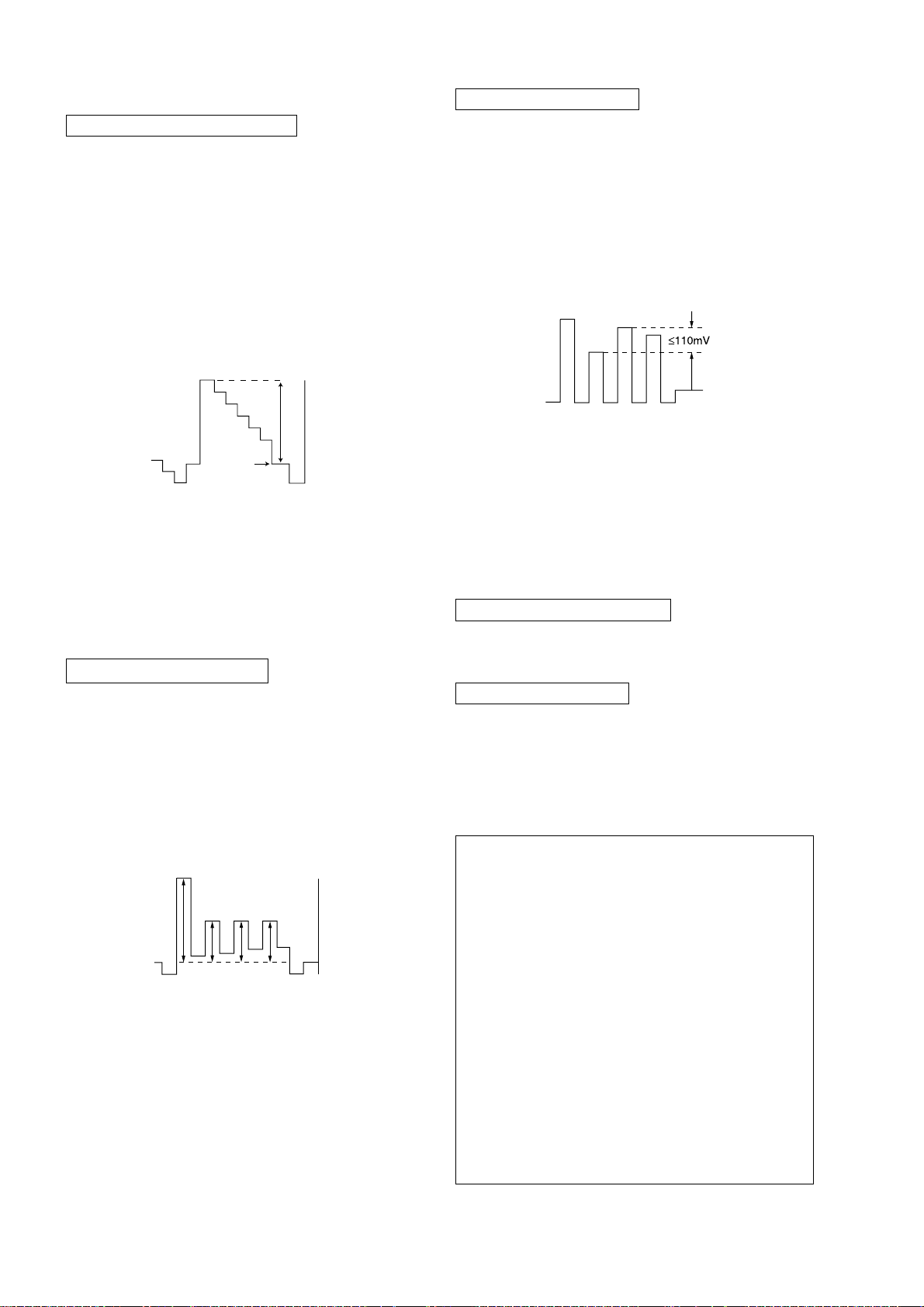
SUB HUE ADJUSTMENT
1. Select Video.
2. Input a NTSC 3.58 Color Bar to TV set.
3. Set the following condition:
PICTURE 100%, COLOR 50%, BRIGHTNESS 50%
4. Connect an oscilloscope to pin 2 (B output) of CN004.
5. Set to Service and adjust SADJ01 "SHUE" with 1
and 4 of commander then adjust to VB1 = VB2 =
VB3 = VB4 with 3 and 6.
6. Then press [MUTING] t - to write the data.
VB1
VB2
VB3
VB4
The highest level of VB1, VB2, VB3, VB4 must be
aligned at the same time.
The ideal difference between VB2 and VB3 is within
±110mV.
For single system with NTSC 4.43 select TV channel
with NTSC 4.43 and repeat 4 t 6.
9. Then press [MUTING] t - to write the data
10. Set "PWL" and "BLBG" back to initial data repectively.
(PWL: 01h and BLGG: 00h)
SUB COLOR ADJUSTMENT
1. Select Video and set Picture mode.
2. Input PAL 100% CB to TV set.
3. Set PICT 06 "WTS" to 00h.
4. Set the following condition:
PICTURE 100%, COLOR 50%, BRIGHTNESS 50%.
5. Connect an oscilloscope to pin 2 (B output) of CN004.
6. Select to Service Mode and adjust SADJ04 "SCOL"
with 1 and 4 of commander then adjust to
VB2 = VB3 = VB4 with 3 and 6.
VB1
VB2 VB3 VB4
VB2 = VB3 = VB4
(Difference is within 70mV)
7. Then press [MUTING] t - to write the data.
8. Set "WTS" back to original data.
3-4. DEFLECTION ADJUSTMENT
H-TRAPEZOID ADJUSTMENT
1. Receive cross hatch/dotsignal.
2. Adjust on to make H-Trapezoid distortion best.
NORMAL MODE (50Hz)
1. Set to Service Mode.
2. Input SPCB Signal (Select Video Mode for USA).
3. Using the 1 and 4 button select GEO (Service
Mode).
4. Rasie/lower data using the 3 and 6 buttons adjust
the following items:-
GEOM : 000 HPOS Horizontal Shift (HS)
001 HPAR Horizontal Parallelogram
002 HBOW Horizontal Bow
003 VLIN Vertical Linearity
004 VSCR Vertical Scroll
005 HSIZ EW Width (EW)
006 EWPW EW Parabola/Width (PW)
007 UCOP EW Upper Corner Parabola
008 LCOP EW Lower Corner Parabola
009 EWTZ EW Trapezium
010 VSLP Vertical Slope (VS)
011 VSIZ Vertical Amplitude
012 SCOR S-Correction (SC)
013 VPOS Vertical Shift (VSH)
014 HBL RGB Blanking Mode
015 WBF Timing of Wide Blanking (WBF)
016 WBR Timing of Wide Blanking (WBR)
017 SBL Service Blanking
018 COPY Copy the GEO data to all
50/60Hz NVM area
5. Write into memory by pressing [MUTING] then - on
the remote commander.
– 28 –
KV-BM14M70/BM14P42/P42/L/P42/V
RM-W101
WIDE MODE (50Hz)
(V-Compression Adjustment)
1. Input SPCB signal.
2. Adjust condition change to WIDE MODE : ON
3. Copy (Item from normal mode 50Hz) all Normal
Mode adjusted data.
NORMAL MODE (60Hz)
1. Input 525/60Hz signal.
2. They can copy 50Hz first.
("COPY" under GEOM is set to
3. Using the
(Service Mode).
4. Raise/lower data using the
obtain optimum image.
GEOM : 000 HPOS Horizontal Shift (HS)
1 and 4 button, select category GEO
001 HPAR Horizontal Parallelogram
002 HBOW Horizontal Bow
003 VLIN Vertical Linearity
004 VSCR Vertical Scroll
005 HSIZ EW Width (EW)
006 EWPW EW Parabola/Width (PW)
007 UCOP EW Upper Corner Parabola
008 LCOP EW Lower Corner Parabola
009 EWTZ EW Trapezium
010 VSLP Vertical Slope (VS)
011 VSIZ Vertical Amplitude
012 SCOR S-Correction (SC)
013 VPOS Vertical Shift (VSH)
014 HBL RGB Blanking Mode
015 WBF Timing of Wide Blanking (WBF)
016 WBR Timing of Wide Blanking (WBR)
017 SBL Service Blanking
018 COPY Copy the GEO data to all
50/60Hz NVM area
1, then [MUTE] + -)
3 and 6 buttons to
WIDE MODE (60Hz)
(V-Compression Adjustment)
1. Input mono scope signal.
2. Adjust condition change to WIDE MODE : ON
3. "COPY" is set to
1, then [MUTE] + -
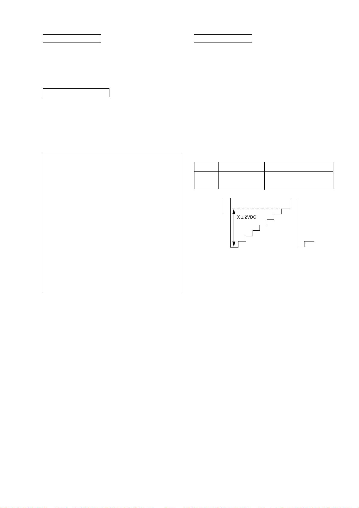
3-5. DRIVE ADJUSTMENT
1. Input signal 70% Color Bar (USA)
100% Color Bar (Other)
2. Make sure only red is active.
3. Set following condition :-
PICTURE 100%, COLOR 0%, Other 50%
4. Select SADJ00 "PMAX" with
until voltage in R out X gain
5. Then press [MUTING] t
X±2VDC (R Cathode on C or CV board)
1 and 4 then adjust
[recorded] = SPEC
- to write data.
Model 14” 21”
GA 83.0 88.0 - Non VM Models
99.0 - VM Models
6. Set VIDP 36 BLBG back to 00.
– 29 –
 Loading...