

Sony KV-AR34M81, KV-AR34N90 Service Manual
REVISION HISTORY
BG3R
CHASSIS
MODEL
KV-AR34M81
KV-AR34N90
NO. SUFFIX DATE SUPPL. / CORR DESCRIPTION
1 -01 2002/09 -- 1st. Issue
PART NO. : 9-872-340-01
SERVICE MANUAL BG3R
CHASSIS
MODEL COMMANDER DEST. CHASSIS NO.
KV-AR34M81 RM-995 ME SCC-U48V-A
KV-AR34N90 RM-996 Taiwan SCC-U54F-A
MODEL COMMANDER DEST. CHASSIS NO.
RM-995RM-996
TRINITRON
®
COLOR TV
KV-AR34M81/AR34N90
RM-995 RM-996
Power requirements 110-240 V AC, 50/60 Hz
Power consumption (W) Indicated on the rear of the TV
Television system B/G, I, D/K, M
Color system PAL, PAL 60, SECAM, NTSC3.58, NTSC4.43
Teletext language English, Farsi (Persian), French
Channel coverage
B/G VHF: E2 to E12 / UHF: E21 to E69
I UHF: B21 to B68 / CATV: S01 to S03, S1 to S41
D/K VHF: C1 to C12, R1 to R12 /
M VHF: A2 to A13 / UHF: A14 to A79
˘(Antenna) 75-ohm external terminal
Audio output (Speaker) 8W + 8W
Number of terminal
DVideo Input: 4* Output: 1 * Three input lines available Phono jacks; 1 Vp-p, 75 ohms
≥ Audio Input: 4* Output: 1 * Three input lines available Phono jacks; 500 mVrms
(S Video) Input : 2 Y: 1 Vp-p, 75 ohms
(Component Input : 1 Phono jacks:
Video) Y: 1 Vp-p, 75 ohms
2 (Headphone) Output: 1 Stereo minijack
Picture tube 34
Tube size (cm) 86 Measured diagonally
Screen size (cm) 80 Measured diagonally
Dimension (w/h/d,mm) 896 × 686 × 569
Mass (kg) 79
SPECIFICATIONS
(KV-AR34M81)
CATV: S01 to S03, S1 to S41
UHF: C13 to C57, R21 to R60 /
CATV: S01 to S03, S1 to S41, Z1 to Z39
CATV: A-8 to A-2, A to W+4, W+6 to W+84
Note
unbalanced, sync negative
C: 0.286 Vp-p, 75 ohms
sync negative
CB: 0.7 Vp-p, 75 ohms
R: 0.7 Vp-p, 75 ohms
C
Audio: 500mVrms
CAUTION
SHORT CIRCUIT THE ANODE OF THE PICTURE TUBE AND
THE ANODE CAP TO THE METAL CHASSIS, CRT SHIELD, OR
CARBON PAINTED ON THE CRT, AFTER REMOVING THE
ANODE.
Design and specifications are subject to change without notice.
SAFETY-RELATED COMPONENT WARNING!!
COMPONENTS IDENTIFIED BY SHADING AND MARK ! ON
THE SCHEMATIC DIAGRAMS, EXPLODED VIEWS AND IN THE
PARTS LIST ARE CRITICAL TO SAFE OPERATION. REPLACE
THESE COMPONENTS WITH SONY PARTS WHOSE PART
NUMBERS APPEAR AS SHOWN IN THIS MANUAL OR IN
SUPPLEMENTS PUBLISHED BY SONY.
– 2 –

KV-AR34M81/AR34N90
RM-995 RM-996
SPECIFICATIONS
(KV-AR34N90)
Note
Power requirements 110 V AC, 60 .Hz
Power consumption (W) Indicated on the rear of the TV
Television system M
Color system NTSC3.58, PAL*, PAL 60*, SECAM*, NTSC4.43* * AV IN only
Stereo/Bilingual System MTS
Channel coverage VHF : 2 to 13 / UHF : 14 to 69 / CATV : 1 to 125
˘(Antenna) 75-ohm external terminal
Audio output (Speaker) 8W + 8W
Number of terminal
Video Input: 4* Output: 1 * Three input lines available Phono jacks; 1 Vp-p, 75 ohms
Audio Input: 4* Output: 1 * Three input lines available Phono jacks; 500 mVrms
(S Video) Input : 2 Y: 1 Vp-p, 75 ohms
unbalanced, sync negative
C: 0.286 Vp-p, 75 ohms
Component Input : 1 Phono jacks:
Video (DVD) IN Y: 1 Vp-p, 75 ohms
sync negative
B: 0.7 Vp-p, 75 ohms
C
R: 0.7 Vp-p, 75 ohms
C
Audio: 500mVrms
2 (Headphone) Output: 1 Stereo minijack
Picture tube 34
Tube size 859 mm Measured diagonally
Screen size 803 mm Measured diagonally
Dimension (w/h/d,mm) 896 × 686 × 569
Mass (kg) 79 kg
CAUTION
SHORT CIRCUIT THE ANODE OF THE PICTURE TUBE AND
THE ANODE CAP TO THE METAL CHASSIS, CRT SHIELD, OR
CARBON PAINTED ON THE CRT, AFTER REMOVING THE
ANODE.
Design and specifications are subject to change without notice.
SAFETY-RELATED COMPONENT WARNING!!
COMPONENTS IDENTIFIED BY SHADING AND MARK ! ON
THE SCHEMATIC DIAGRAMS, EXPLODED VIEWS AND IN THE
PARTS LIST ARE CRITICAL TO SAFE OPERATION. REPLACE
THESE COMPONENTS WITH SONY PARTS WHOSE PART
NUMBERS APPEAR AS SHOWN IN THIS MANUAL OR IN
SUPPLEMENTS PUBLISHED BY SONY.
– 3 –

KV-AR34M81/AR34N90
RM-995 RM-996
TABLE OF CONTENTS
Section Title Page
SELF DIAGNOSTIC FUNCTION ........................................ 5
1. DISASSEMBLY
1-1. Rear Cover Removal ................................................... 8
1-2. Speaker Removal ........................................................ 8
1-3. Chassis Assy Removal ................................................ 8
1-4. F Board Removal ........................................................ 8
1-5. Service Position .......................................................... 8
1-6 HV Cap Block, PWB Holder and
DH Board Removal .................................................... 8
1-7. Terminal Bracket and J Board Removal .................... 9
1-8. D2 Board Removal ..................................................... 9
1-9. H1 and H2 Boards Removal ....................................... 9
1-10. B1 and V1 Boards Removal ....................................... 9
1-11. A and B10 Boards Removal ....................................... 9
1-12. Picture Tube Removal ............................................... 10
2. ADVANCE OPERATION
2-1. "RESET" Function .................................................... 11
3. SET-UP ADJUSTMENTS
3-1. Beam Landing ........................................................... 12
3-2. Convergence .............................................................. 13
3-3. Focus Adjustment ..................................................... 15
3-4. G2 (SCREEN) and White Balance Adjustment ....... 16
4. CIRCUIT ADJUSTMENTS
4-1. Adjustment With Commander .................................. 17
4-2. Adjustment Method .................................................. 17
4-3. Adjustment for Non Digital Texture Enhancer (DTE)
Model ........................................................................ 29
4-4. Adjustment for Digital Texture Enhancer (DTE)
Model ........................................................................ 29
4-5. Display Position Adjustment .................................... 30
4-6. Deflection Adjustment .............................................. 30
4-7. H-Trapezoid Adjustment .......................................... 31
4-8. A Board Adjustment After IC003 (MEMORY)
Replacement .............................................................. 31
4-9. Picture Distortion Adjustment .................................. 32
Section Title Page
5. DIAGRAMS
5-1. Block Diagram .......................................................... 33
5-2. Circuit Board Location ............................................. 35
5-3. Schematic Diagram ................................................... 36
(1) C6 and J Boards Schematic Diagrams ............... 37
(2) A Board Schematic Diagram .............................. 39
(3) D2 Board Schematic Diagram ............................ 43
(4) H1 and F Boards Schematic Diagrams............... 45
(5) B10 Board Schematic Diagram .......................... 47
(6) V1 Board Schematic Diagram ............................ 49
(7) B1 Board Schematic Diagram ............................ 51
(8) DH Board Schematic Diagram ........................... 52
(9) H2 Board Schematic Diagram ............................ 53
(10) VM1 Board Schematic Diagram ...................... 54
5-4. Voltage List and Waveforms ..................................... 56
5-5. Printed Wiring Boards and Parts Location............... 61
5-6. Semiconductors ......................................................... 68
6. EXPLODED VIEWS
6-1. Speaker Bracket ........................................................ 70
6-2. Chassis ...................................................................... 71
6-3. Picture Tube .............................................................. 72
7. ELECTRICAL PARTS LIST ......................................... 73
OPERATING INSTRUCTIONS
– 4 –

KV-AR34M81/AR34N90
RM-995 RM-996
SELF DIAGNOSTIC FUNCTION
The units in this manual contain a self-diagnostic function. If an error occurs, the STANDBY/TIMER lamp will automatically
begin to flash.
The number of times the lamp flashes translates to a probable source of the problem. A definition of the STANDBY/TIMER
lamp flash indicators is listed in the instruction manual for the user’s knowledge and reference. If an error symptom cannot
be reproduced, the remote commander can be used to review the failure occurrence data stored in memory to reveal past
problems and how often these problems occur.
1. DIAGNOSTIC TEST INDICATORS
When an errors occurs, the STANDBY/TIMER lamp will flash a set number of times to indicate the possible cause of the
problem. If there is more than one error, the lamp will identify the first of the problem areas.
Result for all of the following diagnostic items are displayed on screen. No error has occured if the screen displays a “0”.
Diagnostic
Item
Description
• Power does not
turn on
• +B overcurrent
(OCP) or
overvoltage
(OVP)
• Vertical deflection
stopped
• Horizontal
deflection
overdrive
• White balance
failure (no
PICTURE)
No. of times
STANDBY/TIMER
lamp flashes
Does not light
2 times
5 times
Self-diagnostic
display/Diagnostic
result
—
002:000 or
002:001~255
003:001~255
004:001~255
at the same time
005:000 or
005:001~225
Probable
Cause
Location
• Power cord is not plugged
in.
• Fuse is burned out F4601
(F)
• H.OUT Q511 is shorted.
(A board)
• Q701, Q702, Q703 is
shorted (C6 board)
• -13V is not supplied.
(A board)
• IC 503 faulty (A board)
• G2 is improperly adjusted.
(Note 2)
• CRT problem.
• R(Q703), G(Q702) or
B(Q701) out is faulty
(C6 board)
• IC301 is faulty. (A board)
• No connection A board to
C6 board.
Detected
Symptoms
• Power does not come on.
• No power is supplied to the
TV.
• AC power supply is faulty.
• Power does not come on.
• Load on power line is
shorted.
• Has entered standby state
after horizontal raster.
• Vertical deflection pulse is
stopped.
• Power line is shorted or
power supply is stopped.
• No raster is generated.
• CRT cathode current
detection reference pulse
output is small.
• Micro reset
Note 1: If a + B overcurrent is detected, stoppage of the vertical deflection is detected simultaneously.
The symptom that is diagnosed first by the microcontroller is displayed on the screen.
Note 2: Refer to screen (G2) Adjustment in section 3-4 of this manual.
* R(Q703), G(Q702) or B(Q701) out is faulty (C6 board).
—
101:00 or
101:001~225
• Discharge CRT (C6 Board)
• Static discharge
• External noise
• Power is shut down shortly,
after this return back to
normal.
• Detect Micro latch up.
– 5 –
KV-AR34M81/AR34N90
RM-995 RM-996
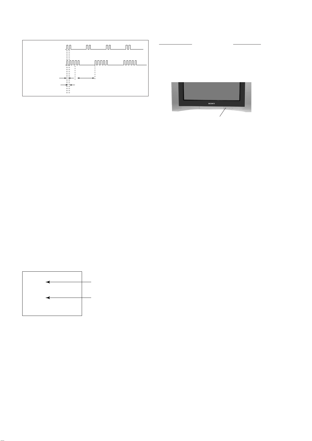
2. DISPLAY OF STANDBY/TIMER LIGHT FLASH COUNT
2 times
+B overcurrent/overvoltage 2 times
Vertical deflection stopped
Diagnostic Item Flash Count*
5 times
Lamp ON 0.3 sec.
Lamp OFF 0.3 sec.
Lamp OFF 3 sec.
White balance failure 5 times
* One flash count is not used for self-diagnostic.
STANDBY/SLEEP lamp
3. STOPPING THE STANDBY/TIMER FLASH
Turn off the power switch on the TV main unit or unplug the power cord from the outlet to stop the STANDBY/TIMER lamp
from flashing.
4. SELF-DIAGNOSTIC SCREEN DIPLAY
For errors with symptoms such as “power sometimes shuts off” or “screen sometimes goes out” that cannot be confirmed, it
is possible to bring up past occurances of failure for confirmation on the screen:
[To Bring Up Screen Test]
In standby mode, press buttons on the remote commander sequentially in rapid succession as shown below:
[Screendisplay] / channel [5] / Sound volume [-] / Power ON
˘
Note that this differs from entering the service mode (mode volume [+]).
Self-Diagnosis screen display
SELF DIAGNOSTIC
002 : 000
003 : 000
004 : 000
005 : 001
101 : 000
Numeral "0" means that no fault has been detected.
Numeral "1" means a fault has been detected.
– 6 –
KV-AR34M81/AR34N90
RM-995 RM-996
5. HANDLING OF SELF-DIAGNOSTIC SCREEN DISPLAY
Since the diagnostic results displayed on the screen are not automatically cleared, always check the self-diagnostic screen
during repairs. When you have completed the repairs, clear the result display to “0”.
Unless the result display is cleared to “0”, the self-diagnostic function will not be able to detect subsequent faults after
completion of the repairs.
[Clearing the result display]
To clear the result display to “0”, press buttons on the remote commander sequentially as shown below when the diagnostic
screen is being displayed.
Channel [8] / 0
[Quitting Self-diagnostic screen]
To quit the entire self-diagnostic screen, turn off the power switch on the remote commander or the main unit.
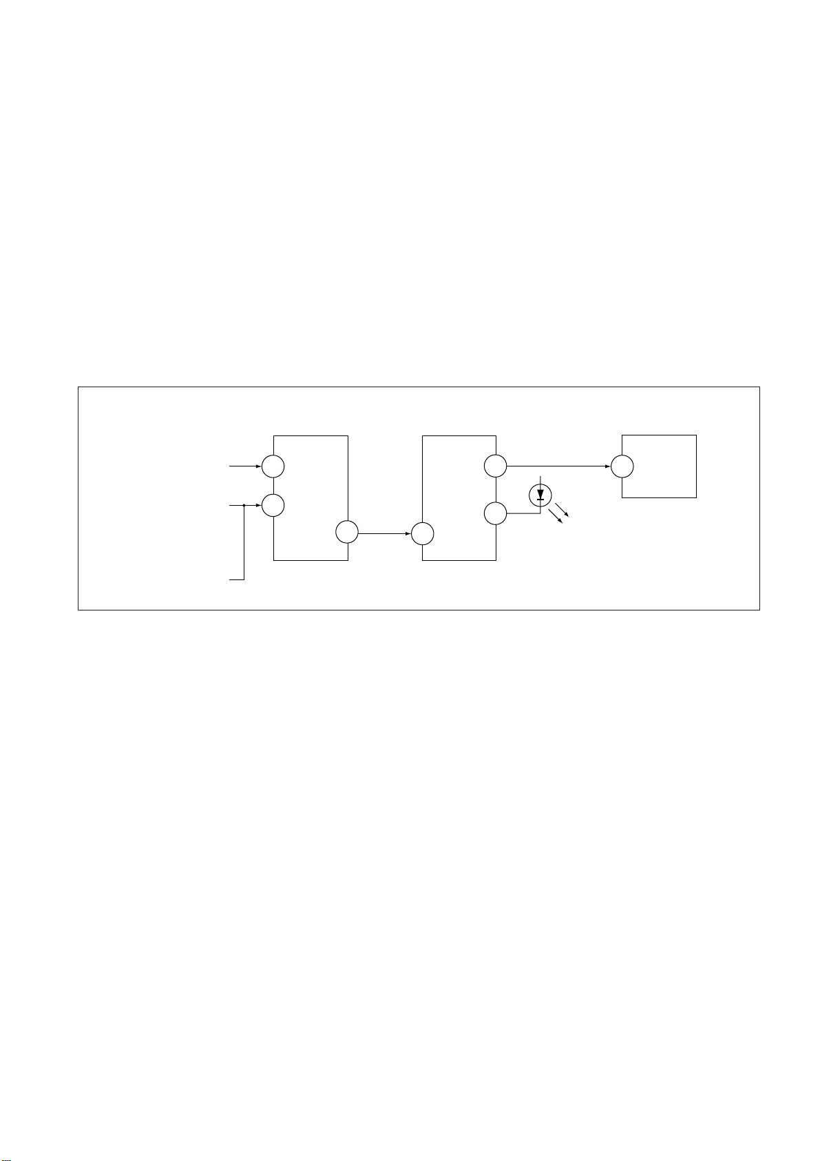
6. SELF-DIANOSTIC CIRCUIT
FROM
CRT
FROM
[+B] Q604 C6
[V] Q509/507
IC301
Y/CHROMA JUNGLE
IK-IN
MP/
18
PROTECT
35
SDA
IC001
SYSTEM
IO-8DAT B-DAT
O-LED
46
IO-SDAT
45
51
IC003
MEMORY
521
[+BovercurrentªOCPº] Occurs when an overcurrent on the +B(135) line is detected by Q604. If Q604 go to ON
and the voltage to pin 18 of IC301 should go down when V.SYNC is more than seven
verticals in a period, the unit will automatically turn off.
[Verticaldeflectionstopped] Occurs when an absence of the vertical deflection pulse is detected by Q509 and IC001
shut down the power supply.
[Verticaldeflectionovercurrent] Occurs when an overcurrent on V drive line is detected by Q507. Power supply will be
shut down when detect this by IC001.
[Whitebalancefailure] If the RGB levels* do not balance or become low level within 5 seconds, this error will be
detected by IC301. TV will stay on, but there will be no picture.
* (Refers to the RGB levels of the AKB detection Ref pulse that detects IK.)
– 7 –
KV-AR34M81/AR34N90
3 Two screws
(+BVTP 4 × 16)
1 Two screws
(+BVTP 4 × 16)
2 Two screws
(Washer Head) (+P4x16)
RM-995 RM-996
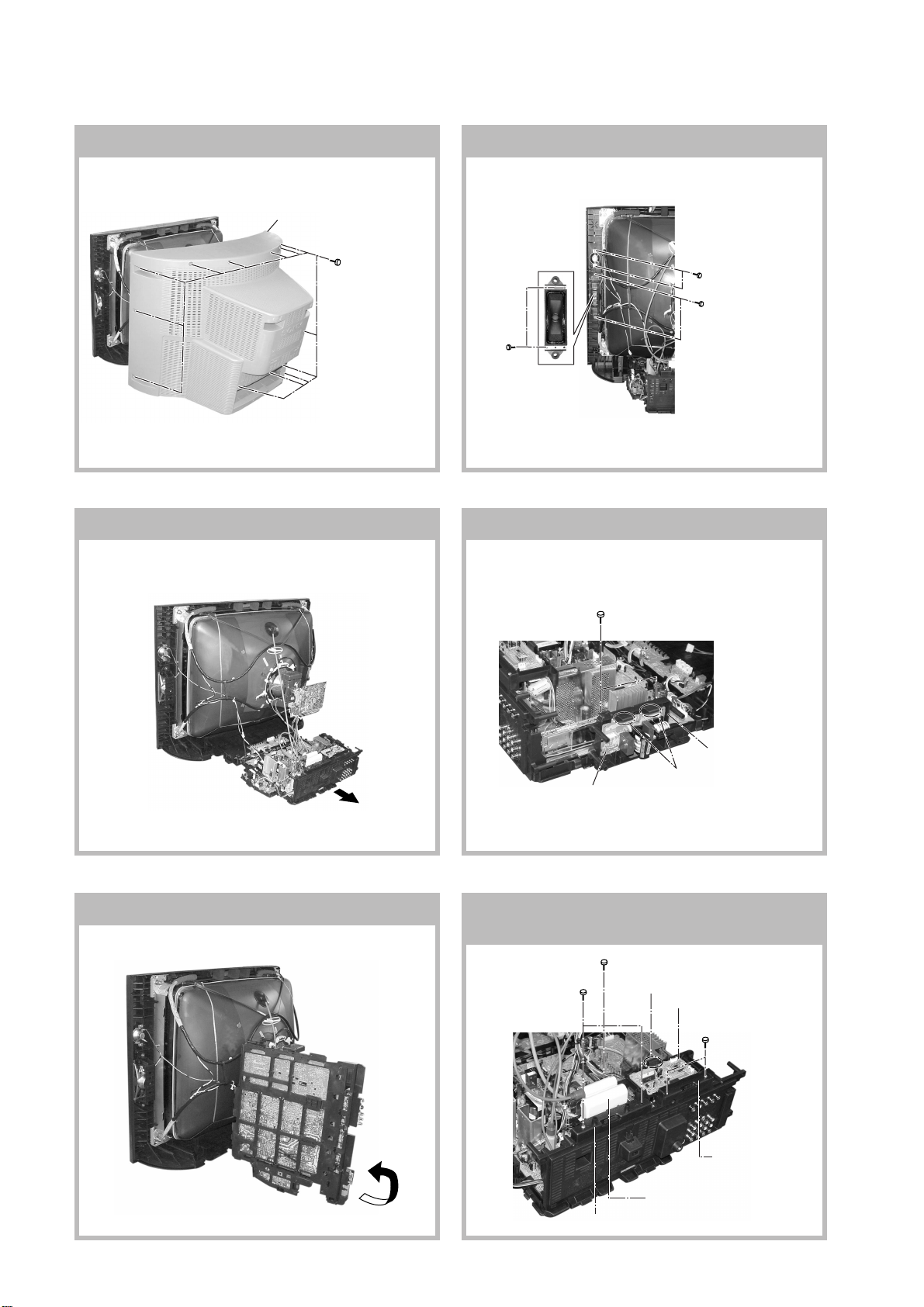
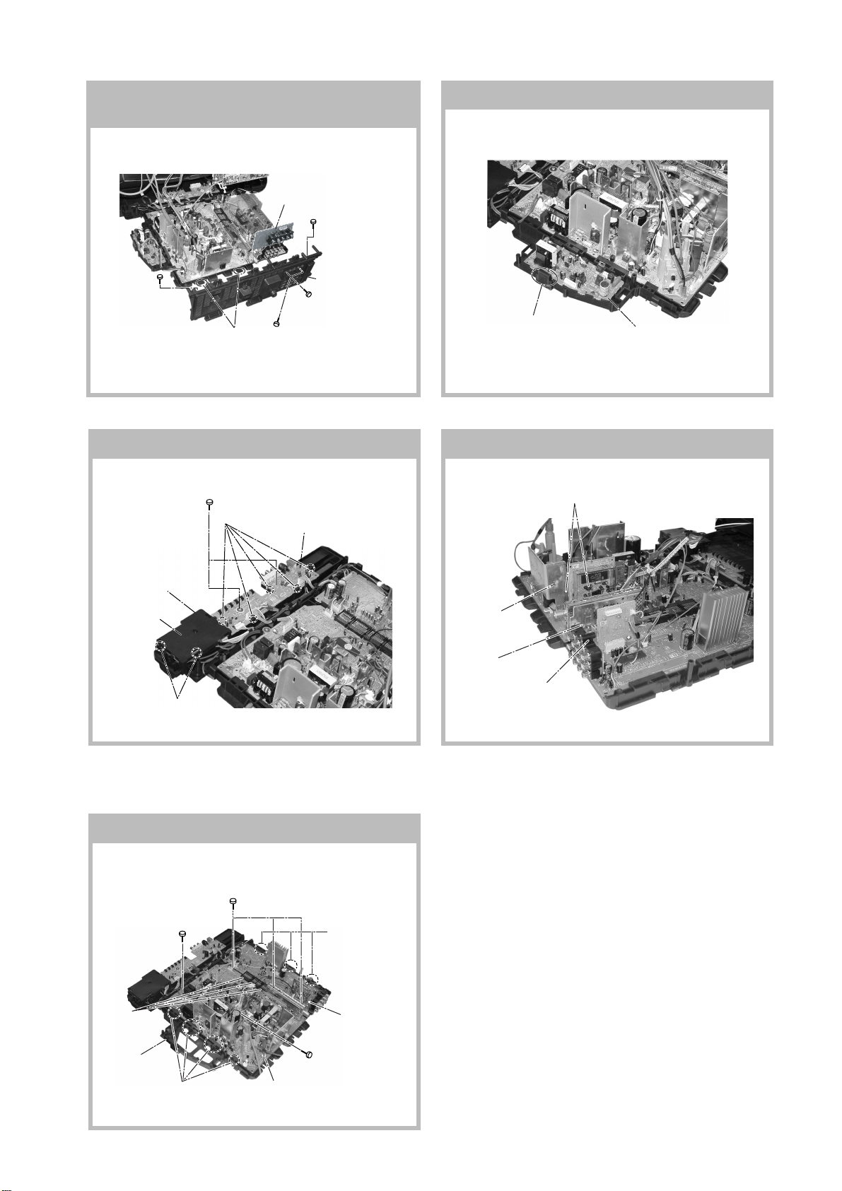
SECTION 1
DISASSEMBLY
1-1. REAR COVER REMOVAL
2 Rear cover
1 Thirteen screws
(+BVTP 4 × 16)
1-2. SPEAKER REMOVAL
1-3. CHASSIS ASSY REMOVAL 1-4. F BOARD REMOVAL
1-5. SERVICE POSITION
1 Two screws (+BVTP 3x12)
2 F Board bracket
4 F Board
3 Two hooks
1-6. HV CAP BLOCK, PWB HOLDER AND
DH BOARD REMOVAL
6 One screw
5 Two screws
(+BVTP 3x12)
(+BVTP 4x16)
4 One Hook
3 DH Board
(KV-AR34N90)
1Two screws
(+BVTP 3x12)
2 PWB holder
7 HV Cap block
8 Bracket HVC
– 8 –
KV-AR34M81/AR34N90
RM-995 RM-996
1-7. TERMINAL BRACKET AND J BOARD
REMOVAL
5 J Board
1 One screw
(+BVTP 3 × 12)
2 One screw
(+BVTP 3 × 12)
6 Two Hooks
3 One screw
(+BVTP 4 × 16)
7 Terminal bracket
4 Two screws
(+BVTP 3 × 12)
1-9. H1 AND H2 BOARDS REMOVAL
1 Two screws (Washer head)
(+BVTP 3 x12)
2 Five hooks
3 H1 Board
1-8. D2 BOARD REMOVAL
1 One Hooks
2 D2 Board
1-10. B1 AND V1 BOARDS REMOVAL
4 Two connectors
6 H2 Board
5 Cover, H
4 Two Hooks
1-11. A AND B10 BOARDS REMOVAL
2 Three screws (Washer head)
1 One screw
(Washer head)
(3 × 12)(+)(BVTP)
(3 × 12)(+) BVTP
7 Three hooks
2 V1 Board
(KV-AR34M81)
1 B1 Board
3 One connector
8 Three
connectors
9 D2 Board
6 Four hooks
4 A Board
5 B10 Board
3 One screw
(Washer head)
(3 × 12)(+)(BVTAP)
– 9 –
KV-AR34M81/AR34N90
c
RM-995 RM-996
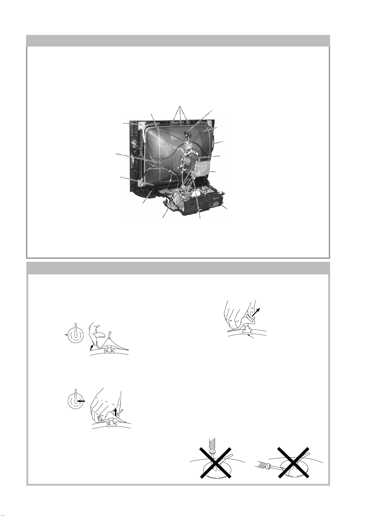
1-12. PICTURE TUBE REMOVAL
Note:
• Please make sure the TV set is not in standing position before removing necessary CRT support located on bottom
right and left.
1) Place the TV set with the CRT face down on a cushion jig.
2) Removal the rear cover.
3) Unplug all interconnecting leads from the Deflection yoke, Neck assy, Degaussing Coil and CRT grounding strap.
qs Earth Coating Assy
!∞ Block Center
4 Anode Cap Removal
!¶ Nut, Special, CRT (4)
!¢ Holder, DGC(2) Removal
qa Spring Tension(2) Removal
0 Support, CRT(2) Removal
8 Loosen the Deflection Yoke
fixing screw and remove
7 VM1 Board Removal
!£ Band, DGC Removal
!§ Degaussing Coil
6 Loosen the Neck Assembly
fixing screw and removal
5 C6 Board Removal
9 Chassis Assy Removal
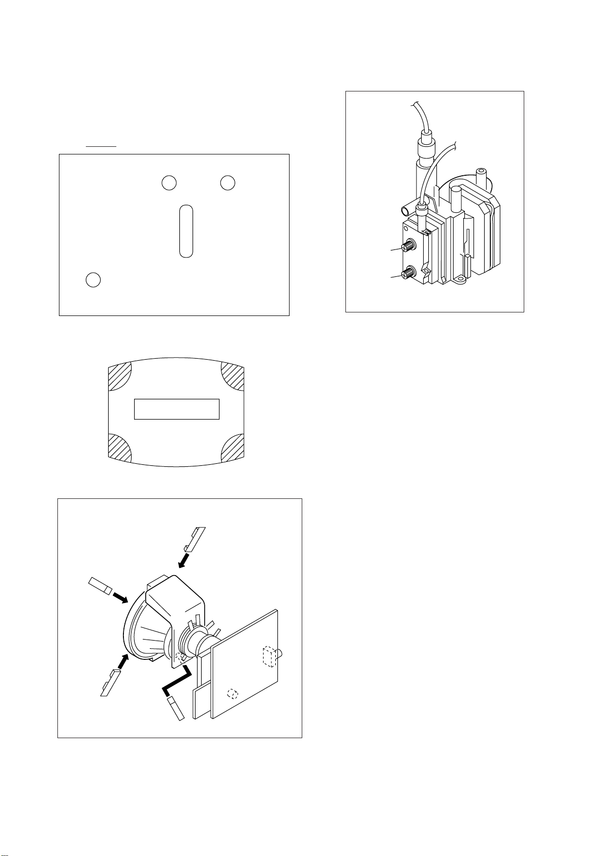
• REMOVAL OF ANODE-CAP
Note:
• After removing the anode, short circuit the anode of the picture tube and the anode cap to the metal chassis, CRT
shield or carbon paint on the CRT.
• REMOVING PROCEDURES
a
a
1 Turn up one side of the rubber cap in the direction
indicated by the arrow a.
b
b
2 Using a thumb pull up the rubber cap firmly in the direc-
tion indicated by the arrow b.
anode button
3 When one side of the rubber cap is separated from the
anode button, the anode-cap can be removed by
turning up the rubber cap and pulling it up in the
direction of the arrow c.
• HOW TO HANDLE AN ANODE-CAP
1 Do not damage the surface of anode-caps with
sharp shaped objects.
2 Do not press the rubber too hard so as not to
damage the inside of anode-cap.
A metal fitting called the shatter-hook terminal is
built into the rubber.
3 Do not turn the foot of rubber over too hard.
The shatter-hook terminal will stick out or damage
the rubber.
– 10 –
KV-AR34M81/AR34N90
RM-995 RM-996
SECTION 2
ADVANCE OPERATION
2-1. "RESET" FUNCTION
1. Purpose
If a customer faces some setting problem that cannot be solved, using the "RESET" function some items will
be reset to its original setting (shipment condition)
2. How to Operate
The way to access to the "RESET" Function:-
a) By pressing "MENU" button or "SELECT" button (for non-menu models) on the Front Key Input and
hold it down for 5 seconds.
3. Subsequent of Operation
Sequential to the resetting operation (either methods being used in No. 2), TV set would shut down once and
automatically turn on again. The power-off duration is expected to be about 500msec. An OSD message,
"RESET" tentatively will be displayed for 10 sec after IK status gets stable.
As a result, some items will be reset to an initial condition (shipment condition) wheareas some other remains
at the last selection by user.
Items that remains at the last selection by user
Channel No., PIC rotation, OSD Language, Skip
Reset Items
Video input RF
Volume 30
Picture mode DYNAMIC
DTE ON (Not used for this models)
Sound mode DYNAMIC
Surround mode OFF
Favourite CH mode AUTO (Not used for this models)
Multi Picture (PIP) OFF (Not used for this models)
PIP position Bottom Right
(Not used for this models)
OSD recall (Not used for this model)
Antenna sensitivity OFF (Not used for this models)
*= only when in RF mode
Antenna sensitivity OFF (Not used for this models)
Antenna sensitivity HIGH* (Not used for this models)
Stereo mode STEREO
Bilingual mode MAIN* (Not used for this models)
High-deviation mode AUTO (Not used for this models)
Child lock OFF*
Wide mode OFF
Game mode OFF (Not used for this models)
Sleep timer OFF
Wake-up timer OFF
Sound muting OFF
– 11 –
KV-AR34M81/AR34N90
RM-995 RM-996
SECTION 3
SET-UP ADJUSTMENTS
• The following adjustments should be made when a complete
realignment is required or a new picture tube is installed.
• These adjustments should be performed with rated power
supply voltage unless otherwise noted.
Perform the adjustments in the following order :
1. Beam Landing
2. Convergence
3. Focus
4. White Balance
Controls and switches should be set as follows unless otherwise noted:
PICTURE control ........................................................... normal
BRIGHTNESS control ................................................... normal
Note : Test Equipment Required.
1. Pattern Generator
2. Degausser
3. Oscilloscope
○○○○○○○○○○○○○○○○○○○○○○○○○○○○○○○○○○○○○○○○○○○○○○○○○○○○○○○○○○○○○○○
Preparation :
• In order to reduce the influence of geomagnetism on the set's
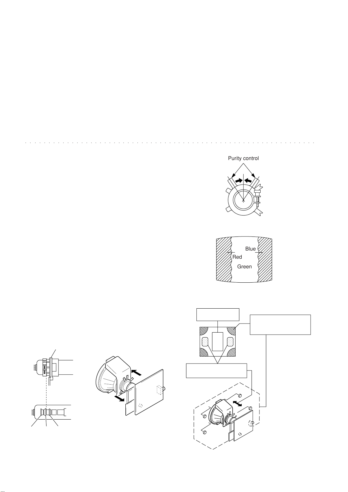
Purity control
picture tube, face it east or west.
• Switch on the set's power and degauss with the degausser.
3-1. BEAM LANDING
1. Input a white signal with the pattern generator.
Contrast
Brightness
2. Position neck assy as shown in Fig3-2.
}
normal
Fig. 3-3
3. Set the pattern generator raster signal to a green raster.
4. Move the deflection yoke to the rear and adjust with the
purity control so that the green is at the center and the blue
and the red take up equally sized areas on each side.
(See Figures 3-1 through 3-4.)
5. Move the deflection yoke forward and adjust so that the
Blue
Red
Green
entire screen is green. (See Figure 3-2.)
6. Switch the raster signal to blue, then to red and verify the
condition.
7. When the position of the deflection yoke has been decided,
Fig. 3-4
fasten the deflection yoke with the screws and DY spacers.
8. If the beam does not land correctly in all the corners, use a
magnet to adjust it.
(See Figure 3-5.)
Purity control
corrects this area.
b
a
Disk magnets or rotatable
disk magnets correct these
areas (a-d).
Neck Assy
Behind the G3 edge
G2G1 G3
Fig. 3-1
Fig. 3-2
– 12 –
c
Deflection yoke positioning
corrects these areas.
a
d
d
Fig. 3-5
b
c
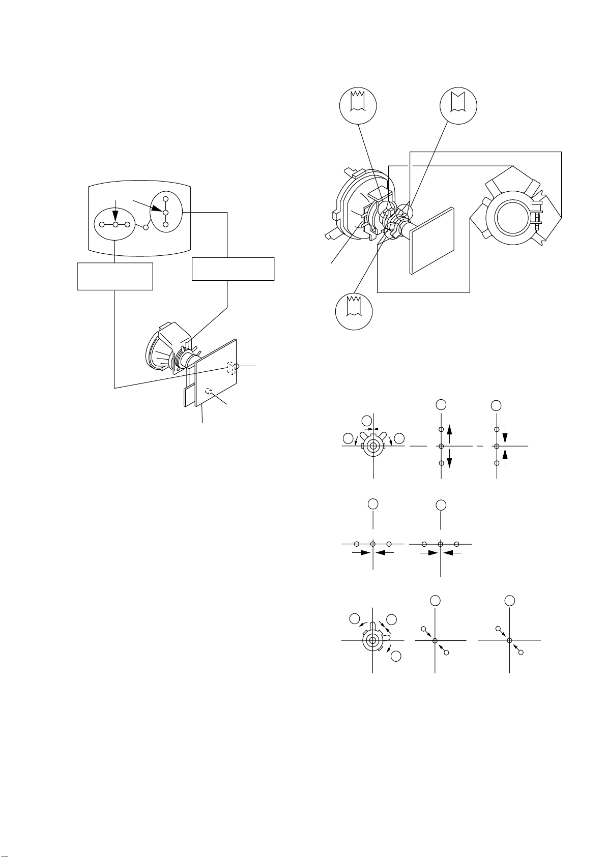
3-2. CONVERGENCE
Purity
BMC
BMC (Hexapole)
Purity
DY pocket
V.STAT
V.STAT
Preparation :
• Before starting this adjustment, adjust the focus, horizontal size
and vertical size.
• Receive dot/hatch signal.
• Pic mode: Personal (Pic 90%, Brightness 50%, Colour 50 %,
Hue 50%, Sharpness 50%).
(1) Horizontal and Vertical Static Convergence
KV-AR34M81/AR34N90
RM-995 RM-996
Center dot
R
GB
H. STAT VR
R
G
B
V. STST
Magnet
RV702
H. STAT
RV701
SCREEN (G2)
C6 Board
1. (Moving horizontally), adjust the H.STAT control so that the
red, green and blue dots are on top of each other at the center of
the screen.
2. (Moving vertically), adjust the V.STAT magnet so that the red,
green and blue dots are on top of each other at the center of the
screen.
3. If the H.STAT variable resistor cannot bring the red, green and
blue dots together at the center of the screen, adjust the
horizontal convergence with the H.STAT variable resistor and
the V.STAT magnet in the manner given below.
(In this case, the H.STAT variable resistor and the V.STAT
magnet influence each other, so be sure to perform adjustments
while tracking.)
1 V. STAT
a
b b
2 H. STAT VR
a
RGGBB
3
a
B
G
R
b
R
a
b
B
G
R
b
– 13 –
b
a
R
b
G
B
B
G
R
KV-AR34M81/AR34N90
RM-995 RM-996
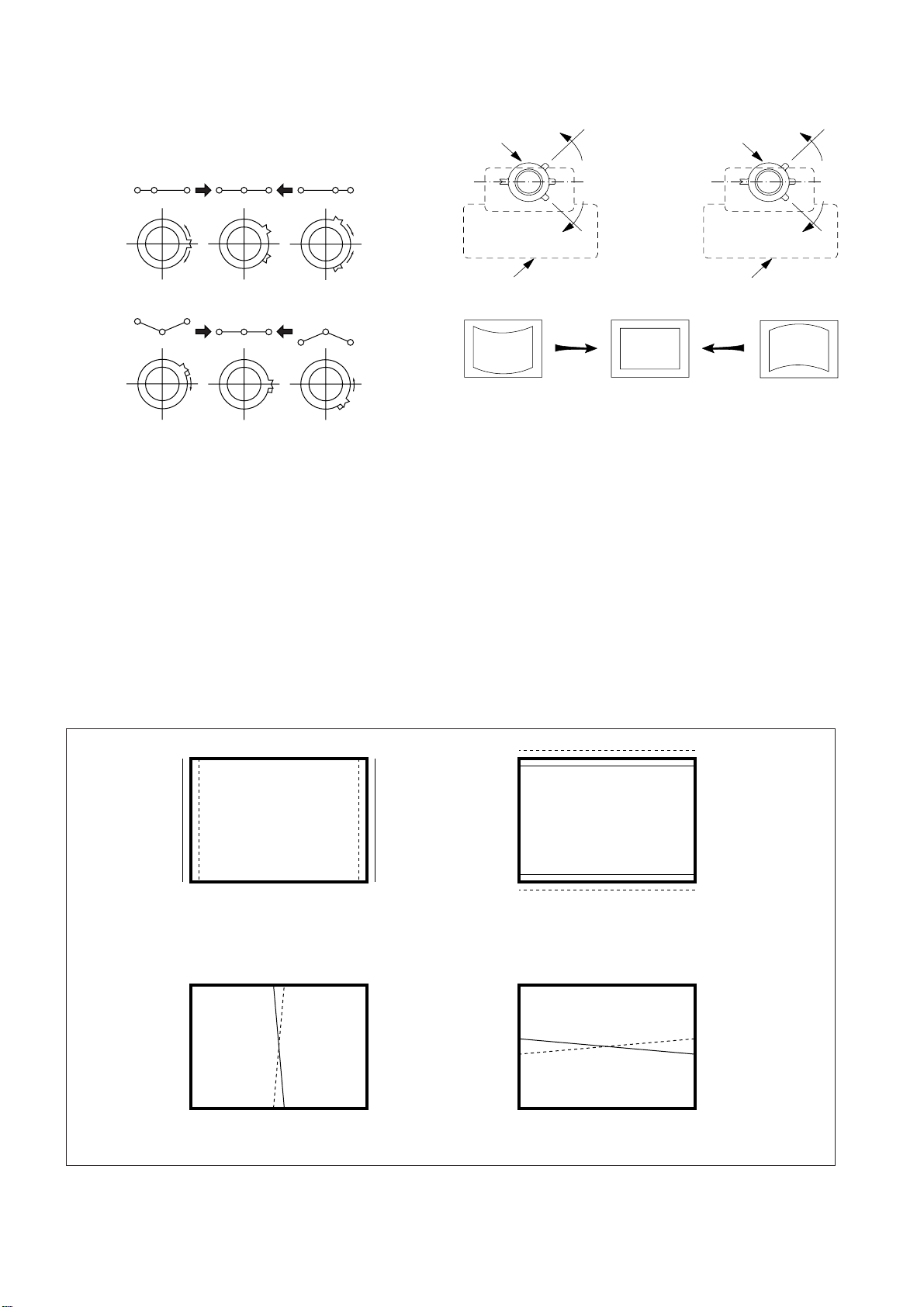
4 BMC (Hexapole) Magnet.
If the red, green and blue dots are not balanced or aligned, then
use the BMC magnet to adjust in the manner described below.
Neck assy Neck assy
Blue
Red
GB
R
R
G
RGB R GB
B
GBRG
R
B
5 Y separation axis correction magnet adjustment.
1. Receive the cross-hatch signal and adjust [PICTURE] to [MIN]
and [BRIGHTNESS] to [STANDARD] .
2. Adjust the Y separation axis correction magnet on the neck
assembly so that the horizontal lines at the top and bottom of
the screen are straight.
Red Blue
VM1 board VM1 board
Note
1. The Red and Blue magnets should be equally far from the
horizontal center line.
2. Do not separate the Red and Blue magnets too far. (Less than
8 mm)
(2) Dynamic Convergence Adjustment
Preparation:
• Before starting this adjustment, adjust the horizontal static
convergence and the vertical static convergence
RB
TLH TLV
RB
B
R
R
B
YCH XCV
– 14 –
KV-AR34M81/AR34N90
RM-995 RM-996
TLV Rotate TLV-2 VOL (29”, 34”) on DY
XCV Rotate XCV Adj core on DY
YCH Rotate YCH VOL on DY
TLH Insert TLH Correction Plate to DY Pocket
(Left or Right)
ON DY:
YCH
TLV1
XCV
TLV2
(3) Screen-corner Convergence
ba
a-d : screen-corner
misconvergence
cd
3-3. FOCUS ADJUSTMENT
FOCUS adjustment should be completed before W/B adjustment.
Focus
Screen
FLYBACK TRANSFORMER (T503)
1. Receive digital monoscope pattern.
2. Set "Picture Mode" to "Standard".
3. Set S2801 to mechanical center position.
4. Adjust focus VR so that the center of the screen becomes just
focus.
5. Adjust S2801 when corner focus is unbalance is right and left.
6. Change the receiving signal to white pattern blue back.
7. Confirm Magenta ring is not noticable. Incase magneta ring is
obvious, reset S2801 to mechanical center position and then
adjust FOCUS VR to balance between MAGENTA RING and
FOCUS.
Fix a Permalloy assy corresponding to the misconverged
areas.
a
d
Permalloy assembly
b
c
– 15 –
KV-AR34M81/AR34N90
RM-995 RM-996
3-4. G2 (SCREEN) AND WHITE BALANCE
ADJUSTMENTS
1. G2 (SCREEN) ADJUSTMENT
1) Set the PICTURE to normal.
2) Put to VIDEO input mode without signals.
3) Connect R, G and B of the C6 board cathode to the
oscilloscope.
4) Adjust BRIGHTNESS to obtain the cathode voltage to the
value below.
5) Adjust G2 (screen) on the FBT until picture shows the point
before cut off.
Cathode setting voltage:
175 V ± 2 (VDC)
0 V
2. WHITE BALANCE ADJUSTMENT
1) Set to Service Mode (Refer Section 4-1: ADJUSTMENTS
WITH COMMANDER).
2) Input white raster signal.
3) Set the PICTURE to minimum.
4) Select WHB 04 "GCT" and WHB 05 "BCT" with [1] and [4],
and adjust the level with [3] and [6] for the best white
balance.
5) Set the PICTURE to maximum.
6) Select WHB 01 "GDR" and WHB 02 "BDR" with [1] and [4],
and adjust the level with [3] and [6] for the best white
balance.
7) Write into the memory by pressing [MUTING] then [0].
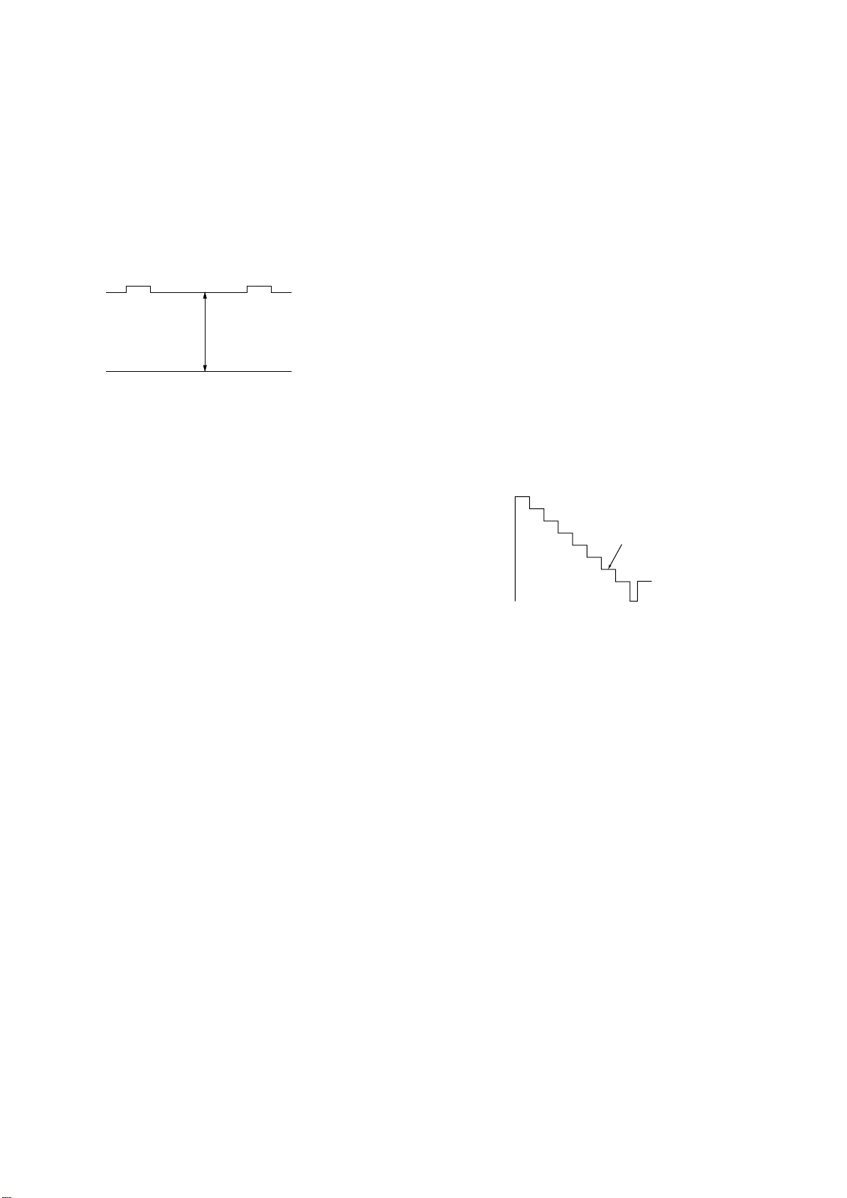
3. SUB BRIGHT ADJUSTMENT
1) Set to service mode.
2) Input a staircase signal of black to white from the pattern
generator.
3) BRIGHTNESS ....50%.
PICTURE ............MINIMUM
4) Select WHB 07 "SBR" with [1] and [4], and adjust WHB 07
"SBR" level with [3] and [6] so that the second stripe from the
right is dimly lit.
White
second from the right
Black
– 16 –
SECTION 4
CIRCUIT ADJUSTMENTS
KV-AR34M81/AR34N90
RM-995 RM-996
4-1. ADJUSTMENTS WITH COMMANDER
Service adjustments to this model can be performed using the
supplied Remote Commander RM-995 and RM-996.
a. ENTERING SERVICE MODE
With the unit on standby
n
[DISPLAY] n 5 n VOL (+) n [POWER]
This operation sequence puts the unit into service mode.
The screen display is :
Device
Name
GEO
605S
(KV-AR34M81)
604S
(KV-AR34N90)
Suffix No
(OEM Code)
Software version Total Power-On time (hours)
b. METHOD OF CANCELLATION FROM SERVICE
MODE
Set the standby condition (Press [POWER] button on the commander),
then press [POWER] button again, hereupon it becomes TV mode.
Item
Name
Item No
00
HPS 1C
1.1M
59 7F 000A
0.2N
Marking of new NVM
Data Mode
p
SERVICE
0
50
PAL,SECAM:50
NTSC :60
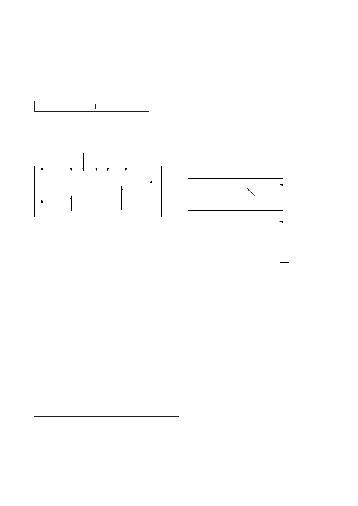
4-2. ADJUSTMENT METHOD
Item Number 00 of device GEO
This explanation uses H-Position as an example.
1. Select “GEO 00 HPS” with the 1 and 4 buttons.
2. Raise/lower the data with the 3 and 6 buttons.
3. Select the optimum state. (The standard is 1F for PAL
reception.)
4. Write with the [MUTING] button. (The display changes to
WRITE.)
5. Execute the writing with the - button. (The WRITE
display will be changed to red color while excuting, and
back to SERVICE.)
Example on screen display :-
GEO 00
605S
(KV-AR34M81)
604S
(KV-AR34N90)
GEO 00
605S
(KV-AR34M81)
604S
(KV-AR34N90)
1.1M
0.2N
1.1M
0.2N
Write with [MUTING]
1F SERVICE 50HPS
7F 0 000A59
1F 50HPS
WRITE
7F 0 000A59
GREEN
Adjusted with 3
and 6 buttons.
GREEN
c. METHOD OF WRITE INTO MEMORY
1) Set to Service Mode.
2) Press [1] (UP) and [4] (DOWN), to select the adjustment.
4) Press [MUTING] button to indicate WRITE on the screen.
5) Press [0] button to write into memory.
d. MEMORY WRITE CONFIRMATION METHOD
1) After adjustment, pull out the plug from AC outlet, and then
plug into AC outlet again.
2) Turn the power switch ON and set to Service Mode.
3) Call the adjusted items again to confirm adjustments were made.
1, 4 Select the adjustment item.
↓
3, 6 Raise/lower the data value.
↓
[MUTING] Writes.
↓
- Executes the writing.
7, - All the data becomes the values in memory.
8, - All user control goes to the standard state.
5, - Service data initialization (Be sure not to use
usually.)
[MUTING], - Write 50Hz adjustment data to 60Hz, or vice
versa.
2, - Copy and write all data.
WRITE
605S
(KV-AR34M81)
604S
(KV-AR34N90)
Write executed with -
1F 50HPSGEO 00
7F 0 000A591.1M
0.2N
RED
The WRITE display
then the display
returns to green
SERVICE.
Use the same method for all Items. Use 1 and 4 to select the
adjustment item, use 3 and 6 to adjust, write with [MUTING],
then execute the write with -.
Note : 1. In [WRITE], the data for all items are written into
memory together.
2. For adjustment items that have different standard data
between 50Hz or 60Hz, be sure to use the respective
input signal after adjustment.
– 17 –
KV-AR34M81/AR34N90
GVTytilanoitcnuF
noitcnuFetoN&elbaTemaNeciveD
)deliateD(eulaVlaitinI/sserddAMVN
yrogetaCoNemaN nommoCCN05CN06CV05CV06
OEG00SPHnoitisoPH )06/05(ediW/)06/05(lamroNS9512AXC
21A021A018M43RA-VK
00SPHnoitisoPH )06/05(ediW/)06/05(lamroN
E1E1E1E109N43RA-VK
10ZSHeziSH )06/05(ediW/)06/05(lamroN
52525252
20PAPpmAniP )06/05(ediW/)06/05(lamroN
F1F1F1F1
30TLTmuizeparT )06/05(ediW/)06/05(lamroN
70707070
40SPVnoitisoPV )06/05(ediW/)06/05(lamroN
F1F1F1F1
50ZSVeziSV )06/05(ediW/)06/05(lamroN
F0F07070
60OCSnoitcerroCS )06/05(ediW/)06/05(lamroN
70707070
70NLVytiraeniLV )06/05(ediW/)06/05(lamroN
70707070
80WOBwoBCFA )06/05(ediW/)06/05(lamroN
70707070
90LGAelgnACFA )06/05(ediW/)06/05(lamroN
70707070
A0NPUniPreppU )06/05(ediW/)06/05(lamroN
F1F1F1F1
B0NPLniPrewoL )06/05(ediW/)06/05(lamroN
F1F1F1F1
C0
LBHffo/nogniknalBH 10
D0
LBLgniknalBHtfeL )06/05(ediW/)06/05(lamroN
A0F0A0F0
E0
LBRgniknalBHthgiR )06/05(ediW/)06/05(lamroN
20202020
GVTytilanoitcnuF
noitcnuFetoN&elbaTemaNeciveD
)deliateD(eulaVlaitinI/sserddAMVN
yrogetaCoNemaN nommoCMACESsrehtOcimanyDsrehtO
BHW00
RDRevirDR srehto/CIMANYDS9512AXC
52A2
10RDGevirDG srehto/CIMANYD
5252
20RDBevirDB srehto/CIMANYD
5252
30
TCRffotuCR srehto/MACES
7070
40TCGffotuCG srehto/MACES
7070
50TCBffotuCB srehto/MACES
7070
60
NMBataDmuminiMssenthgirB 51
70RBSlortnoCssenthgirBbuS 52
80
BPA3#erutciPtnegilletnIrofhctiwSlortnoCthgirBbuS 30
RM-995 RM-996
Adjustment Item Table (Except KV-AR34M60)
– 18 –
KV-AR34M81/AR34N90
GVTytilanoitcnuF
noitcnuFetoN&elbaTemaNeciveD
)deliateD(eulaVlaitinI/sserddAMVN
yrogetaCoNemaN CNCVCNCSTNCNSREHTOCVCSTNCVSREHTOVToediV
JAS00 XMPataDmumixaMerutciP ediW/ediW-nonS9512AXC6313
10UHSlortnoCeuHbuS oediV/VT
7070
20
HSSlortnoCssenprahSbuS ediW/VT
4090
30LCSlortnoCroloCbuS )srehto/CSTN(EDIW/)srehto/CSTN(
321202E1
GVTytilanoitcnuF
noitcnuFetoN&elbaTemaNeciveD
)deliateD(eulaVlaitinI/sserddAMVN
yrogetaCoNemaN nommoCCN05CN06CV05CV06DTS-NONCSTNDTS-NONSREHTODTSCSTNDTSSREHTO
PV00
THEmpoCTHE )06/05(ediW/)06/05(lamroNS9512AXC
50505050
10AMG)edomDRADNATSnidetatapes(noitcerroCammaG )srehto/CSTN(.DTS/)srehto/CSTN(.DTS-NON
30
30
20
20
20GPA3#erutciPtnegilletnIrofhctiwSlortnoCammaG )srehto/CSTN(.DTS/)srehto/CSTN(.DTS-NON
00
00
00
00
GVTytilanoitcnuF
noitcnuFetoN&elbaTemaNeciveD
)deliateD(eulaVlaitinI/sserddAMVN
yrogetaCoNemaN nommoCMACESCSTNLAPDVDTXET
PV30
LDYyaleDY DVD/CSTN/MACES/LAP
90806080
40
TSSnoitisoPtratSDIMACES CSTN&LAP-DECROF/OTUTA&MACES
10
10
50
PSSnoitisoPpotSDIMACES CSTN&LAP-DECROF/OTUTA&MACES
10
10
60
MLRtimiLBGR 00
70
VLSleveLDIMACES CSTN&LAP-DECROF/OTUTA&MACES
20
20
80
FBSOfLLEBMACES CSTN&LAP-DECROF/OTUTA&MACES
22
22
RM-995 RM-996
– 19 –
KV-AR34M81/AR34N90
GVTytilanoitcnuF
noitcnuFetoN&elbaTemaNeciveD
)deliateD(eulaVlaitinI/sserddAMVN
yrogetaCoNemaN nommoCCSTNsrehtOVToediVTXET
PV90
CYDffo/noroloCcimanyD 10
A0
LBA)edomDRADNATStpecxe(gnihctiwSedoMLBA DRADNATStpecxe10
B0
HTVgnihctiwShtVnoitceteDLBA 10
C0
0FSssenprahSrofgnihctiwSOF srehto/CSTN
1010
D0
XCDgnihctiwSoitaR.snarTCD 10
E0
THShctiwSoitartoohsrevO/-erP srehto/CSTN
1010
F0
WDHhctiwShtdiWesluPevirDH 00
01
CFAlortnoCniaGCFA txeT/oediV/VT
100010
11SOHnoitallicsOH 70
21
SSH.peScnySHfoleveLecilS 00
31
SSV.peScnySVfoleveLecilS 00
GVTytilanoitcnuF
noitcnuFetoN&elbaTemaNeciveD
)deliateD(eulaVlaitinI/sserddAMVN
yrogetaCoNemaN nommoCCN05CN06CV05CV06CNCSTNCNSREHTOCVCSTNCVSREHTO
PV41
SMHno/ffom/CnoisiVorcaM S9512AXC
10101010
51
VUYLESY 00
61
VDClangisonrednuFRdnaoediVrofedomDC 10
71
NORNOR 10
81
NOGNOG 10
91
NOBNOB 10
A1
NOPNOP 10
B1
NXAWSSIXA
10101010
C1
LSRLESBGR 00
D1
WBVWKLBV 00
E1
PFRPFER 00
F1
CMVleveLMV 00
02
FBCretliFssapdnaBamorhC 10
12
OTCffOparTamorhC 10
RM-995 RM-996
– 20 –
KV-AR34M81/AR34N90
GVTytilanoitcnuF
noitcnuF
)deliateD(eulaVlaitinI/sserddAMVN
yrogetaCoNemaNnommoCcimanyDamarD/dradnatStfoS/eniF-iHwsbanyDwsbamarDwsbtfoS
2PA00
SBBgnitteSleveLtsooBssaB30
10
BCBlortnoCssaBbuSroftcelestuctsooB00
20
SBSgnitteSleveLssaBbuS00
30
TCBlortnoCelberTbuSroftcelestuctsooB00
40
STSgnitteSleveLelberTbuS00
50
LGAgnitteSleveLCGA00
60
WSBhctiwSFFO/NOtsooBssaB00
70
SABlortnoCedomdnuosssaB
113030113030
80
ERTlortnoCedomdnuoselberT
414120414120
90
EBBlortnoCedomdnuoSEBB
98C60098C600
GVTytilanoitcnuF
noitcnuFemaNeciveD
)deliateD(eulaVlaitinI/sserddAMVN
yrogetaCoNemaN nommoCMACESCSTNLAP
PSM00
TSWdlohserhToeretSG/W05143PSM51
10
TBWdlohserhTlaugniliBG/W CE
20
LLWdlohserhTlaruanoMG/W 50
30
CAWtnuoCtnemeergAG/W 10
40
LDWyaleDhcraeSG/W 03
50
LDNyaleDhcraeSMACIN 02
60
LDSyaleDdaeRsutatsoeretS 01
70
CGAtnatsnoC/otuAhctiwSCGA 10
80
LERedoMtnatsnoCtaniaGCGA 82
90
MRCffo/nognitumreirraC 00
A0
OCAffo/notuokcolCoiduA 10
B0
PFmetsysM-nonrofelacserPMF B1
C0
MPFmetsysMrofelacserPMF 23
D0
HFVEDHrofelacserPMF 63
E0
MHFMdnaVEDHrofelacserPMF 56
F0
PGWelacserPG/W C1
01
PINelacserPMACIN F7
11
RREdlohserhThctiwsMFotuA 05
21
RREh0ff7oth0007niagrekaepSduoL D6
RM-995 RM-996
– 21 –
KV-AR34M81/AR34N90
GVTytilanoitcnuF
noitcnuFemaNeciveD
)deliateD(eulaVlaitinI/sserddAMVN
yrogetaCoNemaN nommoCMACESCSTNLAP
PIP00
ORPelbanEedoMnacSevieergorP05143PSM00
10
DERedoMelbuoDdaeR 00
20
IEFtceleSdleiF 00
30
SPHnoitisoPerutciPlatnoziroH 33
40
SPVnoitisoPerutciPlacitreV B1
50
PFHgninoitisoPeniFlatnoziroH 80
60
PFVgninoitisoPeniFlacitreV 00
70
SIDdradnatsyalpsiD 00
80
SOHmooZlatnoziroH 00
90
SEVnoitcudeResioNeluPcnySlacitreV 00
A0
SPFdradnatStneraPecroF 00
B0
MZHmooZlatnoziroH 00
C0
PSVnoitcudeResioNeluPcnySlacitreV 10
D0
LDVyaleDesluPcnySlacitreV 00
E0
HRFlatnoziroHhtdiWemarF 50
F0
VWFlacitreVhtdiWemarF 20
01
DRVnoitcudeR 00
11
KBVgniknalBlacitreV 00
21
YLDyaleDtceleS 10
31
RCPnoitcerroCnoitisoP 00
41
MGAedoMCGA 30
51
CGAeulaVlortnoCniaGcitamotuA 90
61
NVCtceleSSBVC 00
71
DPCnoitaruDGNIPMALC 10
81
TPCtratsesluPGNIPMALC 10
91
MULtesffoecnanimuL 00
RM-995 RM-996
– 22 –
KV-AR34M81/AR34N90
GVTytilanoitcnuF
noitcnuF
)deliateD(eulaVlaitinI/sserddAMVN
yrogetaCoNemaNMACESCSTNLAPVToediVDVD
PIPA1
LLPtnatsnoCemiTLLPtresnI
0000
B1
DCYyaleDC/Y808080
80
C1
RSNIIPtesnirofnoitcudeResioN
2000
GVTytilanoitcnuF
noitcnuFetoN&elbaT
)deliateD(eulaVlaitinI/sserddAMVN
yrogetaCoNemaN nommoC0506
PIPD1
PSLdeepSnoitacifitnedIdradnatS 00
E1
LIKdlohserhTrelliKroloC 20
F1
PGBnoitisoPetaGtsruB 10
02
CESleveLnoitacifitnedIMACES 10
12
MEDnoitceleswsahpmeeD 10
22
AMChtiwdnaBamorhC 00
32
CFIretliFnoitasnepmoCFI 20
42
EUHeuH 00
52
ACStnemtsujdAreirracbuSroloC 60
62
NOCtnemtsujdAtsartnoC 00
72
RLBlennahCdeRleveLgniknalB 00
82
TRBtnemtsujdAssenthgirB 30
92
GLBlennahCneerGleveLgniknalB 00
A2
RIBlennahCdeRnoisrevnIgniknalB 00
B2
BIBlennahCeulBnoisrevnIgniknalB 00
C2
BLBlennahCeulBleveLgniknalB 00
D2
TNIlavretnIhserfeR 00
E2
RKPlennahCdeRleveLkaeP 58
F2
GKPlennahCneerGleveLkaeP 58
03
BKPlennahCeulBleveLkaeP 58
13
YRFYroloCemarF 90
23
TUOtamroFtuptuO 10
33
URFYroloCemarF 00
43
VRFVroloCemarF 00
53
TAStnemtsujdAnoitarutaSroloC 90
63
KDYtnemtsujdAkaePY 30
73
OCYelbanEgniroCY 10
83
LAPleveLDILAP 30
93
VOPlacitreVtesffOnoitisoP 00
A3
HOPlatnoziroHtesffOnoitisoP 00
B3
HSVknirhSlacitreV 00
C3
HSHknirhSH 00
D3
LPChtgneLesluPGNIPMALC 10
RM-995 RM-996
– 23 –
KV-AR34M81/AR34N90
GVTytilanoitcnuF
noitcnuFemaNeciveD
)deliateD(eulaVlaitinI/sserddAMVN
yrogetaCoNemaN NOMMOCTUPNI-SVTOEDIV
TCY00UHStnemtsujdAeuHbuSQA3612AXC
E0
21
10
GNPhtdiWetaGCSTN/LAP 10
20
INPWSytivitisneSCSTN/LAP 00
GVTytilanoitcnuF
noitcnuFetoN&elbaTemaNeciveD
)deliateD(eulaVlaitinI/sserddAMVN
yrogetaCoNemaN NOMMOCVT05OEDIV05DVD05VT06OEDIV06DVD06
TCY30
LCSlortnoCroloCbuSoediV/VT*06/05QA3612AXC
50
70
50
70
40
TCSlortnoCtsartnoCbuSoediV/VT*06-05
50
80
50
80
50
0FSgnignahCycneuqerFretneCssenprahS 20
60
QEScitsiretcarahCrezilauqEssenprahS 00
70
GHSlortnoCniaGssenprahSDVD/oediV/VT*06/05
7080A06080A0
80LOYlortnoCleveLtuptuo-Y 12
90
PSBgnignahCtnioPtratShtcertSkcalB 00
RM-995 RM-996
– 24 –
KV-AR34M81/AR34N90
GVTytilanoitcnuF
noitcnuFetoN&elbaTemaNeciveD
)deliateD(eulaVlaitinI/sserddAMVN
yrogetaCoN
emaN NOMMOCTUPNI-SVTOEDIVDVDSREHTO
TCYA0
LOClortnoCleveLtuptuOrC/bC QA3612AXC
72 E1
B0
RCDtnemtsujdAoitaRnoitarotseRCD 00
C0
0FBtnemtsujdA0FFQT/FPB 10
D0
QFBtnemtsujdAQFQT/FPB 20
E0
WSFhctiwSFQT/FPB 10
F0
TDShctiwSparTelbuoDMACES 10
01
FPLhctiwSFPLrC/bC/Y 10
11
LDYtnemtsujdAemiTLD-YDVD/tupni-S/oediV/VT
50605050
21
TMChctiwSetuMtuptuOrC/bC 00
31
10B)etuorniam(tnemtsujdA1tesffObC 70
41
1ORtnemtsujdA1tesffOrC 70
51
FDChctiwSycneuqerFnwoDtnuoCV langisonrofzH05decrof00
61
MDChctiwSegduJnwoDtnuoCV 00
71
CFAhctiwSytivitisneSCFADVD/oediV)/VT(
0000
81
MVMksaMCFA+ksaMnoisivorcaM 10
91
YRStnemtsujdAkcalBY-RMACES 70
A1
YBStnemtsujdAkcalBY-BMACES 10
B1
LEBgnihctiwSFPH/LLEBMACES 20
C1
FLBtnemtsujdA0fLLEB 00
D1
IVShctiwSDI-VMACES 00
E1
PGStnemtsujdAnoitisoPetaGMACES 00
F1
DIShctiwSytivitisneSMACESMACEStpecxe10
02
HIShctiwSnoitibihnIMACES 00
12
PTSsulpLAProfputeSleveLkcalBY 00
22
WSAWSedoMtceleSoediVotuA 10
32
HSWnoitcuderesionrofpetSniaGssenprahS 00
42
OCWnoitcuderesionrofpetSleveLtuptuOrC/bC 00
52
2BC)tupni2rCbCY(tnemtsujbatesffo2bC 70
62
2RC)tupni2rCbCY(tnemtsujbatesffo2rC 70
72
HPHhctiwsesahptuptuOSH 00
82
HPVesahptuptuoPVrofhctiwS 00
92
MCNBMOCCSTN 00
RM-995 RM-996
– 25 –
KV-AR34M81/AR34N90
GVTytilanoitcnuF
noitcnuFetoN&elbaTemaNeciveD
)deliateD(eulaVlaitinI/sserddAMVN
yrogetaCoN
emaN NOMMOCCSTNSREHTO
ET00
0RNRNsrehtO/CSTNETD
1010
10
0CTgniroCETsrehtO/CSTN
5050
20
0GTniaGETsrehtO/CSTN
5050
30
HTSssapybET:1ssapybETdecroF 00
40
FOC)215(FFO:1FFOtnenopmoCroloC 00
50
FOYFFO:1FFOtnenopmoCecnanimuL 00
60
RJV2PS:32PS:21PS:1NO:0lortnocrettijV 00
70
FOTFFOET:1FFOET 00
80
FODFFORNtoD:1FFORNtoD 00
90
FOFFFOFPL:1FFOFPLET 10
A0
HTCFFO:1FFOETroloC 00
B0
LSPnoitceleSretemaraPET 20
C0
PLCleveLpmalCtupnI 80
D0
2LCleveLpmalCtuptuO 80
E0
1AL)etihW,+(niaGdnepedleveL 00
F0
2AL)kcalB,+(niaGdnepedleveL 10
01
3AL)etihW,-(niaGdnepedleveL F0
11
4AL)kcalB,-(niaGdnepedleveL 10
21
WRCoitarnoitasnepmocC/YET 40
31
DCYtnemtsujdayaledtuptuoC/YET 40
41
OSOtesffossenprahsffO 00
RN00
OMD)edoMomeD=1(FFO/NOedoMomeDRN ETD00
10
VHTnoitceridlacitrevrofleveldlohserhTesioNfotesffO 30
20
HHTnoitceridlatnozirohrofleveldlohserhTlevelfotesffO 11
30
LLBleveLkcalBrofnoitcetedleveLfotesffO 70
40
TSCleveLroloCrofnoitcetedleveLfotesffO 70
50
CHTdlohserhTnoitceteDegdEfotesffO 90
60
FRN0=knaRsyawla0RN 00
70
GID)nIlatigiD=1(nIlatigiDronID/A 00
TXT00
HXTnoitisoPlatnoziroHtxeteleT 1625AAS00
10
VXTnoitisoPlacitreVtxeteleT 00
MPO00HSOnoitisoPHDSO 790057PXC
F0
10
MOC ]ETD[)enoN:3,D3:2,itluM:1,enoN:0(/]ETD-NON[)D3:3,itluM:2,CSTN:1,enoN:0(noitceleSbmoC 20
RM-995 RM-996
– 26 –
KV-AR34M81/AR34N90
GVTytilanoitcnuF
noitcnuFetoN&elbaTemaNeciveD
)deliateD(eulaVlaitinI/sserddAMVN
yrogetaCoN
emaN NOMMOCCSTNsrehtO
MPO20
CPAhctiwSCPA 790057PXC10
30
YSTotuAtasySVT 00
40
TUMetuMlangiSoN 10
50
MFAhctiwsMFotuA 10
60
BFRlortnoCFPB-C 00
70
OVTtesffoelgnA-VottliT 30
80
LBDnoitcnuFkcabeulBelbasiD 00
90
OSS)x8:3,x6:2,x4:1,ffO:0(noitpOhcraeSdeepS 10
A0
HCSnoitidnoCgnippihSrofnoitceleSHCylnosledoMCSTN70
B0
ACSnoitidnocgnippihsrofnoitcelesriA/elbaCylnosledoMCSTN10
C0
ROPTCYmorFnoitcetceDteseRnOrewoP 00
D0
CRNISCIProfretnuoCteD-N F1
E0
CURdekcolnUretfaretnuocegnahclangiSFR F0
F0
CLRdekcoLretfaretnuocegnahclangiSFR F0
01
PYBISCIPssapyB 00
11
LBPgniknalBFFO/NOISCIP 00
BPO00
1PO)SEGAPDEIFICEPSees(1stiBlanoitpOstiB-noitpO
10
2PO)SEGAPDEIFICEPSees(2stiBlanoitpO
20
3PO)SEGAPDEIFICEPSees(3stiBlanoitpO
30
4PO)SEGAPDEIFICEPSees(4stiBlanoitpO
RM-995 RM-996
shaded items are fixed data.
NOTE
•
In case of a device replacement, adjustment by rewriting the data value is necessary for some items.
• Standard data listed on the Adjustment Item Table are reference values, therefore it may be different for each model and for each mode.
• Note for Different Data Those are the standard data values written on the microprocessor. Therefore, the data values of the modes and stored respectively in the memory.
– 27 –
KV-AR34M81/AR34N90
RM-995 RM-996
ITEM INFORMATION
No. OPB0 OP1
Item
KV-AR34M81
KV-AR34N90
No. OPB1 OP2
Item
KV-AR34M81
KV-AR34N90
AV Input 00 = no AV Input 01 = 1 AV Input
DVD Input Effective only when "AV Input" is set to 3 AV Input
PIP 4 PIP 4 0 = disabled, 1 = enabled
No. OPB2 OP3
Item
KV-AR34M81
KV-AR34N90
XTAL 4.43
1
1
TOP
0
0
Initial Menu
1
1
XTAL 3.58
1
1
NICAM
0
0
AP2
1
1
SECAM
1
1
HDEV
0
0
2nd. Lang
1
1
Thai Bil
0
0
B/G
1
0
PIP4
0
0
10 = 2 AV Input 11 = 3 AV Input
Auto PIC
1
1
A-TVsys
0
0
US ST
0
1
I
1
0
DVD Input
1
1
DTE
0
0
D/K
1
0
AV Input
1
1
Forced 50/60
0
0
M
1
1
1
1
Colour SW*
2
1
1
Initial Menu Initial Men Setup 0 = disabled, 1 = enabled
AP2 Auto Processor Selection 0 = AP, 1 = AP2.
Auto PIC
*3
A-TVsys Auto TV System in Auto Program0 = disabled, 1 = enabled
*
US ST
DTE DTE Model Selection 0 = Non DTE, 1 = DTE
Forced 50/60 Forced to 50/60 Hz during no signal condition 0=60Hz, 1=50Hz
Color SW
Note:*1 - For XA21/XH29 Models Only
No. OPB3 *OP4
*2
- For XA34/29/25 Models Only
*3
- For PNC3, the enables are from service item APG and APB.
Item
KV-AR34M81
KV-AR34N90
*2
PNC2
0
1
Korean ST
0
0
Auto Picture Improvement 0 = off PNC1/PNC2
1 = activate PNC1/PNC2
USA Stereo 0 = disabled, 1 = enabled
Color Data Selection in Dynamic Mode 0 = 65 (No PIP), 1 = 57 (PIP)
Vid NTSC3.58
0
0
Wide
1
1
Video3
0
0
Chinese(Multi mdl)
1
0
Arabic/C.Chinese
Thai/Korean
1
1
1
0
APPLICABLE TO XS ONLY - Sub Language Selection (Bit 0 - Bit 2)
Korean Stereo* Korean Stereo 0 = disabled, 1 = enabled
2
PNC2*
Enable switch of PNC2 0 = disable, 1 = enable
Video NTSC3.58* Video Color System 0 = Multi System, 1 = Single System (NTSC3.58)
Wide Enable wide mode 0 = disable, 1 = enable
Note : *APPLICABLE FOR NTSC MODELS ONLY
– 28 –
KV-AR34M81/AR34N90
VY
RM-995 RM-996
4-3. ADJUSTMENT FOR NON DIGITAL TEXTURE
ENHANCER (DTE) MODEL
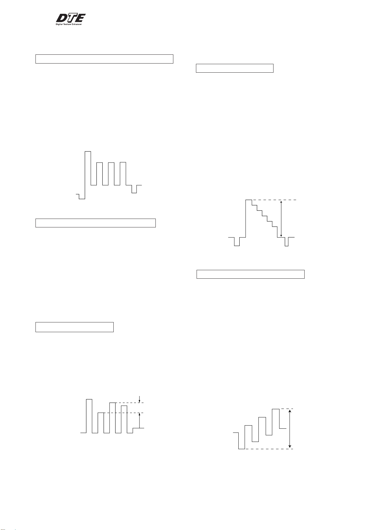
SUB COLOR ADJUSTMENT (KV-AR25/AR29)
1. Select Video.
2. Input PAL Color Bar
3. Set to following condition PICTURE 100%, BRIGHTNESS
50%, Color 50%.
4. Connect an oscilloscope to pin 1 (BOUT) of CN305, A Board.
5. Set the service mode and select SAJ 3 ‘SCL’ with 1 and 4 of
the commander then adjust the VB2=VB3=VB4 3 and 6.
6. Press
7. Input NTSC Color Bar to set and repeat items (3 to 7).
8. Select "WIDE" mode, write the "SAME DATA- 3 STEPS" for
[MUTING] → - of the commander to write the data.
both PAL and NTSC Color Bar input.
VB1
VB2 VB3
VB2 = VB3 = VB4
VB2 = VB3 = VB4 (Difference is within 70mV)
VB4
4-4. ADJUSTMENT FOR DIGITAL TEXTURE
ENHANCER (DTE) MODEL
(not used for this models)
Y LEVEL ADJUSTMENT
1. Select Video.
2. Input PAL Color Bar to TV set (white reference 100%).
3. Set the following condition:
DTE : ON
Picture Mode : Dynamic
4. Connect an oscilloscope to pin 1 (CV/Y in) of CN106, A
Board.
5. Set to Service Mode and YCT 08 ‘YOL’ with 1 and 4 of the
commander then adjust to VY within spec with 3 and 6.
6. Then press
7. Select RF.
8. Repeat item 2 to 4.
9. Set to Service Mode and YCT 04 ‘SCT’ with 1 and 4 of the
commander then adjust to VY within spec with 3 to 6.
10. Copy SCT data to NTSC (RF).
[MUTING] → - to write the data.
SCT Setting (Video Mode) : 07h (NTSC & PAL)
SUB COLOR ADJUSTMENT (KV-AR34)
1. Select Video.
2. Input PAL Color Bar
3. Set to following condition PICTURE 100%, BRIGHTNESS
50%, Color 50%.
4. Connect an oscilloscope to pin 1 (BOUT) of CN305, A Board.
5. Set the service mode and select SAJ 3 ‘SCL’ with 1 and 4 of
the commander then adjust the VB2=VB3=VB4 3 and 6.
6. Press
[MUTING] → - of the commander to write the data.
7. Add 6 steps and save the data.
8. Input NTSC Color Bar to TV set and repeat items 3 to 7.
9. Select "WIDE" mode, write the "SAME DATA- 3 STEPS" for
both PAL and NTSC Color Bar input.
SUB HUE ADJUSTMENT
1. Select Video 1.
2. Input a NTSC 3.58 color-bar, video into Video 1.
3. Set the following condition:
PICTURE 100%, BRIGHTNESS 50%, COLOR 50%
4. Connect an oscilloscope to pin 1 (B OUT) of CN305, A board.
5. Select SAJ 1 "SHU" with 1 and 4 of the commander by
setting to Service Mode and adjust to VB1=VB2=VB3=VB4
with 3 and 6.
VB1
VB2
VB3
VB4
± 110mV
SPEC: VY : 1.2 Vpp ± 0.05m Vpp
SUB COLOR (YCT) ADJUSTMENT
1. Select Video.
2. Input NTSC Color Bar.
3. Set the following condition:
DTE : ON
Picture Mode : Dynamic
NTSC 75% Color Bar
4. Connect an oscilloscope to pin 2 (B-Y in) of CN303, A Board.
5. Set to Service Mode and YCT 0A ‘COL’ with 1 and 4 of the
commander then adjust to VB within spec with 3 and 6.
6. Then press
7. Select RF.
8. Repeat item no 2 to 4.
9. Set to Service Mode and YCT 03 ‘COL’ with 1 and 4 of the
commander then adjust the waveform within spec with 3 and
6.
10. Then press
11. Input PAL Color Bar (75%) and repeat item no 8 to 10.
[MUTING] → - to write the data.
[MUTING] → - to write the data.
VB1 = VB2 = VB3 = VB4
The highest level of VB1,VB2,VB3,VB4 must be aligned at
the same line. Ideal difference level between VB2 and VB3
should be within ± 110mV.
6. Press [MUTING] → - of the commander to write the data.
7. Adjust SAJ 1 "SHU" as step 3 to 6 when receiving TV mode.
VB
SPEC :
VIDEO : VB = 0.931 Vpp ± 50 mVpp
RF : VB = 0.931 Vpp ± 50 mVpp
– 29 –
 Loading...