

Sony KV-AR29M90 Service Manual
REVISION HISTORY
BG3R
CHASSIS
MODEL
KV-AR29M90
NO. SUFFIX DATE SUPPL. / CORR DESCRIPTION
1 -01 2002/5 -- 1st. Issue
PA RT NO. : 9-872-312-01
SERVICE MANUAL
BG3R
CHASSIS
MODEL COMMANDER DEST. CHASSIS NO.
KV-AR29M90 RM-993 Hong Kong SCC-U50F-A
MODEL COMMANDER DEST. CHASSIS NO.
TRINITRON
®
COLOR TV
KV-AR29M90
RM-993
Power requirements 220-240 V AC, 50/60Hz
Power consumption (W) Indicated on the rear of the TV
Television system B/G, I, D/K, M
Color system PAL, PAL 60, SECAM, NTSC3.58, NTSC4.43
Stereo/Bilingual System NICAM Stereo/Bilingual B/G, I, A2 Stereo/Bilingual B/G
Channel coverage
B/G VHF: E2 to E12 / UHF: E21 to E69
I UHF: B21 to B68 / CATV: S01 to S03, S1 to S41
D/K VHF: C1 to C12, R1 to R12
M VHF: A2 to A13 / UHF: A14 to A79
˘(Antenna) 75-ohm external terminal
Audio output (Speaker) 8W + 8W
Number of terminal
DVideo Input: 4* Output: 1 * Three input lines available Phone jacks; 1 Vp-p, 75 ohms
≥ (Audio) Input: 4* Output: 1 * Three input lines available Phone jacks; 500 mVrms
Video) Y: 1 Vp-p, 75 ohms
2 (Headphone) Output: 1 Stereo minijack
Picture tube 29 in
Tube size (cm) 72 measured diagonally
Screen size (cm) 68 measured diagonally
Dimension (w/h/d,mm) 765 × 578 × 502
Mass (kg) 49
SPECIFICATIONS
Note
CATV: S01 to S03, S1 to S41
UHF: C13 to C57, R21 to R60
CATV: S01 to S03, S1 to S41, Z1 to Z39
CATV: A-8 to A-2, A to W+4, W+6 to W+84
(S Video) Input : 2 Y: 1 Vp-p, 75 ohms
unbalanced, sync negative
C: 0.286 Vp-p, 75 ohms
(Component Input : 1 Phono jacks:
sync negative
CB: 0.7 Vp-p, 75 ohms
R: 0.7 Vp-p, 75 ohms
C
Audio: 500mVrms
CAUTION
SHORT CIRCUIT THE ANODE OF THE PICTURE TUBE AND
THE ANODE CAP TO THE METAL CHASSIS, CRT SHIELD, OR
CARBON PAINTED ON THE CRT, AFTER REMOVING THE
ANODE.
Design and specifications are subject to change without notice.
SAFETY-RELATED COMPONENT WARNING!!
COMPONENTS IDENTIFIED BY SHADING AND MARK ! ON
THE SCHEMATIC DIAGRAMS, EXPLODED VIEWS AND IN THE
PARTS LIST ARE CRITICAL TO SAFE OPERATION. REPLACE
THESE COMPONENTS WITH SONY PARTS WHOSE PART
NUMBERS APPEAR AS SHOWN IN THIS MANUAL OR IN
SUPPLEMENTS PUBLISHED BY SONY.
– 2 –

TABLE OF CONTENTS
KV-AR29M90
RM-993
Section Title Page
SELF DIAGNOSTIC FUNCTION ........................................4
1. DISASSEMBLY
1-1. Rear Cover Removal ................................................... 7
1-2. Speaker Removal ........................................................ 7
1-3. Chassis Assy Removal ................................................ 7
1-4. F Board Removal ........................................................ 7
1-5. Service Position .......................................................... 7
1-6. Terminal Bracket and J Board Removal .................... 7
1-7. D3 Board Removal ..................................................... 8
1-8. B1 Board Removal...................................................... 8
1-9. H1 and H2 Boards Removal ....................................... 8
1-10. A and B10 Boards Removal ....................................... 8
1-11. Picture Tube Removal ................................................. 9
2. ADVANCE OPERATION
2-1. "RESET" Function .................................................... 10
3. SET-UP ADJUSTMENTS
3-1. Beam Landing ........................................................... 11
3-2. Convergence.............................................................. 12
3-3. Focus Adjustment ..................................................... 14
3-4. G2 (SCREEN) and White Balance Adjustment ....... 15
Section Title Page
5. DIAGRAMS
5-1. Block Diagram .......................................................... 27
5-2. Circuit Boards Location ........................................... 29
5-3. Schematic Diagram ................................................... 30
(1) C6 Board Schematic Diagram ............................ 31
(2) A Board Schematic Diagram .............................. 33
(3) B10 Board Schematic Diagram .......................... 37
(4) B1 and D3 Boards Schematic Diagrams ............ 39
(5) F and VM1 Boards Schematic Diagrams ........... 41
(6) H1 Board Schematic Diagram ............................ 43
(7) J Board Schematic Diagram ............................... 45
(8) H2 Board Schematic Diagram ............................ 46
5-4. Voltage List and Waveforms..................................... 48
5-5. Printed Wiring Boards and Parts Location ............... 53
5-6. Semiconductors......................................................... 61
6. EXPLODED VIEWS
6-1. Speaker Bracket ........................................................ 62
6-2. Chassis ...................................................................... 63
6-3. Picture Tube .............................................................. 64
7. ELECTRICAL PARTS LIST ......................................... 65
4. CIRCUIT ADJUSTMENTS
4-1. Adjustment With Commander .................................. 16
4-2. Adjustment Method .................................................. 16
4-3. Adjustment for Non Digital Texture Enchancer
(DTE) Model ............................................................. 24
4-4. Adjustment for Digital Texture Enchancer
(DTE) Model ............................................................. 24
4-5. Display Position Adjustment .................................... 25
4-6. Deflection Adjustment .............................................. 25
4-7. Picture Distortion Adjustment .................................. 26
OPERATING MANUAL
– 3 –

KV-AR29M90
RM-993
SELF DIAGNOSTIC FUNCTION
The units in this manual contain a self-diagnostic function. If an error occurs, the STANDBY/TIMER lamp will automatically
begin to flash.
The number of times the lamp flashes translates to a probable source of the problem. A definition of the STANDBY/TIMER
lamp flash indicators is listed in the instruction manual for the user’s knowledge and reference. If an error symptom cannot
be reproduced, the remote commander can be used to review the failure occurrence data stored in memory to reveal past
problems and how often these problems occur.
1. DIAGNOSTIC TEST INDICATORS
When an errors occurs, the STANDBY/TIMER lamp will flash a set number of times to indicate the possible cause of the
problem. If there is more than one error, the lamp will identify the first of the problem areas.
Result for all of the following diagnostic items are displayed on screen. No error has occured if the screen displays a “0”.
Diagnostic
Item
Description
• Power does not
turn on
• +B overcurrent
(OCP) or
overvoltage
(OVP)
• Vertical deflection
stopped
• Horizontal
deflection
overdrive
• White balance
failure (no
PICTURE)
No. of times
STANDBY/TIMER
lamp flashes
Does not light
2 times
5 times
Self-diagnostic
display/Diagnostic
result
—
002:000 or
002:001~255
003:001~255
004:001~255
at the same time
005:000 or
005:001~225
Probable
Cause
Location
• Power cord is not plugged
in.
• Fuse is burned out F4601
(F)
• H.OUT Q511 is shorted.
(A board)
• Q701, Q702, Q703 is
shorted (C6 board)
• -13V is not supplied.
(A board)
• IC 503 faulty (A board)
• G2 is improperly adjusted.
(Note 2)
• CRT problem.
• R(Q703), G(Q702) or
B(Q701) out is faulty
(C6 board)
• IC301 is faulty. (A board)
• No connection A board to
C6 board.
Detected
Symptoms
• Power does not come on.
• No power is supplied to the
TV.
• AC power supply is faulty.
• Power does not come on.
• Load on power line is
shorted.
• Has entered standby state
after horizontal raster.
• Vertical deflection pulse is
stopped.
• Power line is shorted or
power supply is stopped.
• No raster is generated.
• CRT cathode current
detection reference pulse
output is small.
• Micro reset
Note 1: If a + B overcurrent is detected, stoppage of the vertical deflection is detected simultaneously.
The symptom that is diagnosed first by the microcontroller is displayed on the screen.
Note 2: Refer to screen (G2) Adjustment in section 3-4 of this manual.
* R(Q703), G(Q702) or B(Q701) out is faulty (C6 board).
—
101:00 or
101:001~225
• Discharge CRT (C6 Board)
• Static discharge
• External noise
• Power is shut down shortly,
after this return back to
normal.
• Detect Micro latch up.
– 4 –
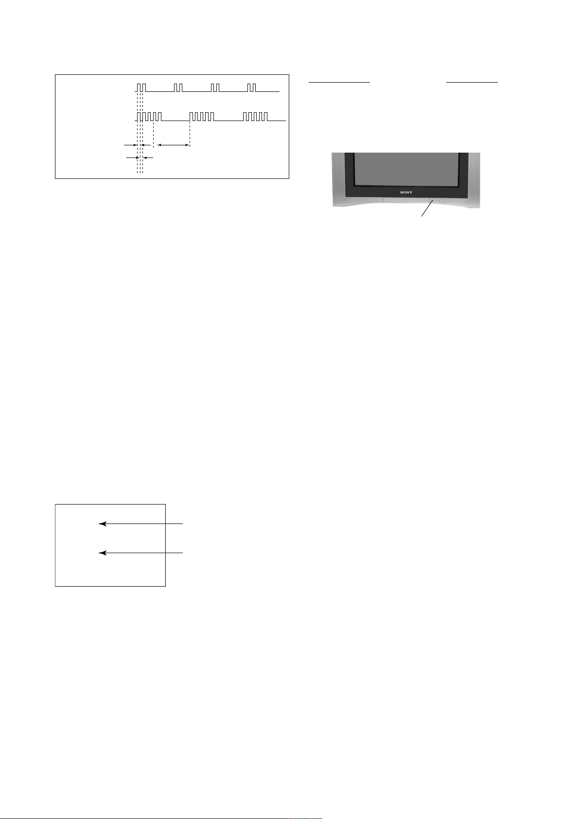
2. DISPLAY OF STANDBY/TIMER LIGHT FLASH COUNT
KV-AR29M90
RM-993
2 times
+B overcurrent/overvoltage 2 times
Vertical deflection stopped
Diagnostic Item Flash Count*
3 times
Lamp ON 0.3 sec.
Lamp OFF 0.3 sec.
Lamp OFF 3 sec.
White balance failure 5 times
* One flash count is not used for self-diagnostic.
STANDBY/SLEEP lamp
3. STOPPING THE STANDBY/TIMER FLASH
Turn off the power switch on the TV main unit or unplug the power cord from the outlet to stop the STANDBY/TIMER lamp
from flashing.
4. SELF-DIAGNOSTIC SCREEN DIPLAY
For errors with symptoms such as “power sometimes shuts off” or “screen sometimes goes out” that cannot be confirmed, it
is possible to bring up past occurances of failure for confirmation on the screen:
[To Bring Up Screen Test]
In standby mode, press buttons on the remote commander sequentially in rapid succession as shown below:
[Screendisplay] / channel [5] / Sound volume [-] / Power ON
˘
Note that this differs from entering the service mode (mode volume [+]).
Self-Diagnosis screen display
SELF DIAGNOSTIC
002 : 000
003 : 000
004 : 000
005 : 001
101 : 000
Numeral "0" means that no fault has been detected.
Numeral "1" means a fault has been detected.
– 5 –
KV-AR29M90
RM-993
5. HANDLING OF SELF-DIAGNOSTIC SCREEN DISPLAY
Since the diagnostic results displayed on the screen are not automatically cleared, always check the self-diagnostic screen
during repairs. When you have completed the repairs, clear the result display to “0”.
Unless the result display is cleared to “0”, the self-diagnostic function will not be able to detect subsequent faults after
completion of the repairs.
[Clearing the result display]
To clear the result display to “0”, press buttons on the remote commander sequentially as shown below when the diagnostic
screen is being displayed.
Channel [8] / 0
[Quitting Self-diagnostic screen]
To quit the entire self-diagnostic screen, turn off the power switch on the remote commander or the main unit.
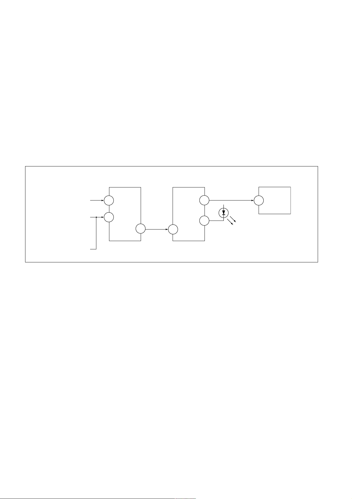
6. SELF-DIANOSTIC CIRCUIT
FROM
CRT
FROM
[+B] Q604 C6
[V] Q509/507
IC301
Y/CHROMA JUNGLE
IK-IN
MP/
18
PROTECT
35
SDA
IC001
SYSTEM
IO-8DAT B-DAT
O-LED
46
IO-SDAT
45
51
IC003
MEMORY
521
[+BovercurrentªOCPº] Occurs when an overcurrent on the +B(135) line is detected by Q604. If Q604 go to ON
and the voltage to pin 18 of IC301 should go down when V.SYNC is more than seven
verticals in a period, the unit will automatically turn off.
[Verticaldeflectionstopped] Occurs when an absence of the vertical deflection pulse is detected by Q509 and IC001
shut down the power supply.
[Verticaldeflectionovercurrent] Occurs when an overcurrent on V drive line is detected by Q507. Power supply will be
shut down when detect this by IC001.
[Whitebalancefailure] If the RGB levels* do not balance or become low level within 5 seconds, this error will be
detected by IC301. TV will stay on, but there will be no picture.
* (Refers to the RGB levels of the AKB detection Ref pulse that detects IK.)
– 6 –

SECTION 1
DISASSEMBLY
KV-AR29M90
RM-993
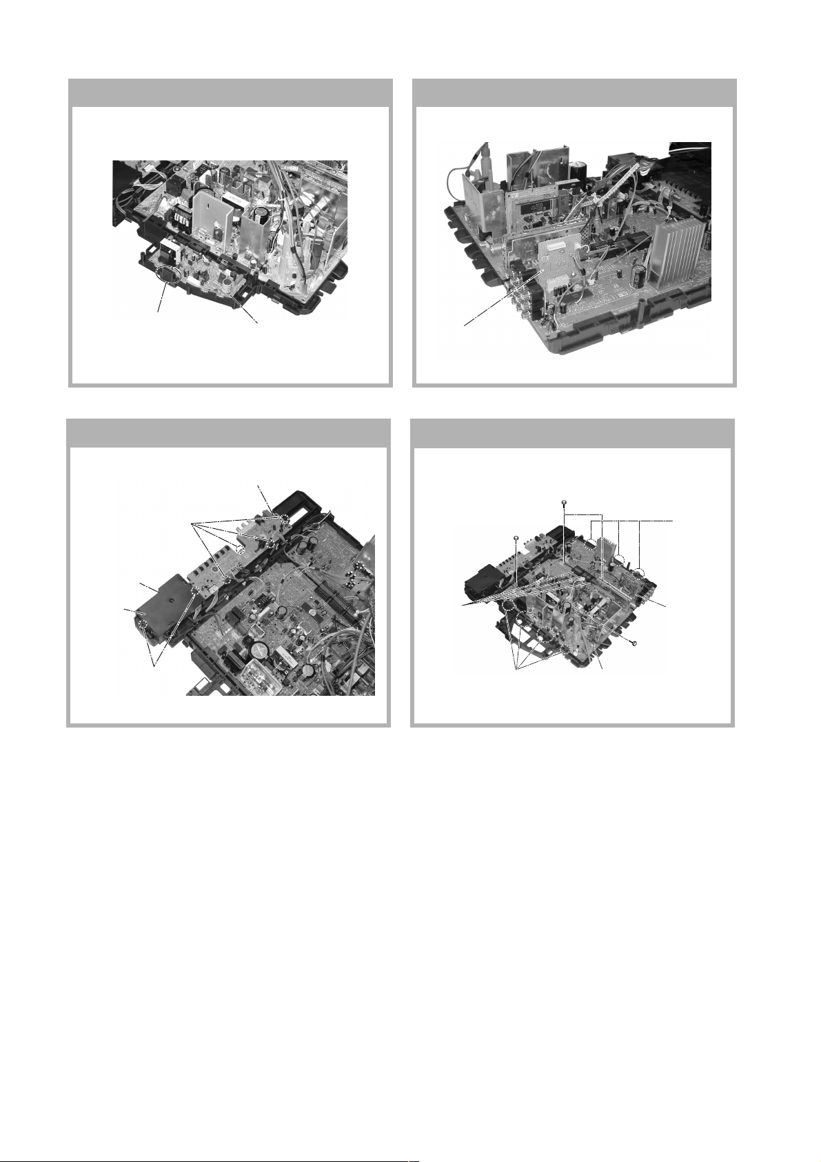
1-1. REAR COVER REMOVAL
2 Rear cover
1 Night screws
(+BVTP 4 × 16)
1-2. SPEAKER REMOVAL
3 Two screws
(+BVTP 4 × 16)
1-3. CHASSIS ASSY REMOVAL 1-4. F BOARD REMOVAL
1 Two screws
(+BVTP 4 × 16)
2 Two screws
(Washer Head) (+P4x16)
1 Two screw
(Washer Head) (+P4x16)
2 F Board bracket
3 Two hooks
4 F Board
1-5. SERVICE POSITION 1-6. TERMINAL BRACKET AND J BOARD
REMOVAL
6 J Board
1 One screw
(+BVTP 3 × 12)
– 7 –
1 One screw
(+BVTP 3 × 12)
2 Two Hooks
4 Terminal bracket
5 Two screws
(+BVTP 4 × 16)
3 One screw
(+BVTP 4 × 16)
KV-AR29M90
RM-993
1-7. D3 BOARD REMOVAL 1-8. B1 BOARD REMOVAL
1 One Hooks
2 D3 Board
1-9. H1 AND H2 BOARDS REMOVAL
2 H1 Board
1 Four hooks
5 H2 Board
4 Cover, H
3 Two hooks
2 B1 Board
1-10. A AND B10 BOARDS REMOVAL
2 Two screws
(3 × 12)(+) BVTP
5 One screw
(3 × 12)(+)(BVTP)
1 Three connectors
5 One screw
(3 × 12)(+)(BVTP)
6 Four hooks
7 A Board
3 Three hooks
4 B10 Board
– 8 –

KV-AR29M90
c
1-11. PICTURE TUBE REMOVAL
Note:
• Please make sure the TV set is not in standing posotion before removing necessary CRT support located on bottom
right and left.
1) Place the TV set with the CRT face down on a cushion jig.
2) Removal the rear cover.
1 Anode Cap Removal
qa Earth Coating Assy
RM-993
qs Nut, locking
8 Holder, DGC(2)
Removal
q; Spring Tension(2)
Removal
5 Loosen the Neck Assembly
fixing screw and removal
4 VM1 Board Removal
7 Band, DGC Removal
9 Degaussing Coil
3 Loosen the Neck Assembly
fixing screw and removal
2 C6 Board Removal
6 Chassis Assy Removal
• REMOVAL OF ANODE-CAP
Note:
• After removing the anode, short circuit the anode of the picture tube and the anode cap to the metal chassis, CRT
shield or carbon paint on the CRT.
• REMOVING PROCEDURES
a
a
1 Turn up one side of the rubber cap in the direction
indicated by the arrow a.
b
b
2 Using a thumb pull up the rubber cap firmly in the direc-
tion indicated by the arrow b.
anode button
3 When one side of the rubber cap is separated from the
anode button, the anode-cap can be removed by
turning up the rubber cap and pulling it up in the
direction of the arrow c.
• HOW TO HANDLE AN ANODE-CAP
1 Do not damage the surface of anode-caps with
sharp shaped objects.
2 Do not press the rubber too hard so as not to
damage the inside of anode-cap.
A metal fitting called the shatter-hook terminal is
built into the rubber.
3 Do not turn the foot of rubber over too hard.
The shatter-hook terminal will stick out or damage
the rubber.
– 9 –
KV-AR29M90
RM-993
SECTION 2
ADVANCE OPERATION
2-1. "RESET" FUNCTION
1. Purpose
If a customer faces some setting problem that cannot be solved, using the "RESET" function some items will
be reset to its original setting (shipment condition)
2. How to Operate
The way to access to the "RESET" Function:-
a) By pressing "MENU" button or "SELECT" button (for non-menu models) on the Front Key Input and
hold it down for 5 seconds.
3. Subsequent of Operation
Sequential to the resetting operation (either methods being used in No. 2), TV set would shut down once and
automatically turn on again. The power-off duration is expected to be about 500msec. An OSD message,
"RESET" tentatively will be displayed for 10 sec after IK status gets stable.
As a result, some items will be reset to an initial condition (shipment condition) wheareas some other remains
at the last selection by user.
Items that remains at the last selection by user
Channel No., Favourite CH Setup,
PIC rotation, OSD Language, Fine tuning, TV System, Skip
Reset Items
Video input RF
Volume 30
Picture mode DYNAMIC
PICSI
Sound mode DYNAMIC
Surround mode OFF
Favourite CH mode AUTO
Multi Picture (PIP) OFF
PIP position Bottom Right
OSD recall OFF
Antenna sensitivity OFF
*= only when in RF mode
Antenna sensitivity HIGH*
Stereo mode STEREO
Bilingual mode MAIN*
High-deviation mode AUTO
Child lock OFF*
Wide mode OFF
Game mode OFF
Sleep timer OFF
Wake-up timer OFF
Sound muting OFF
– 10 –
SECTION 3
SET-UP ADJUSTMENTS
KV-AR29M90
RM-993
• The following adjustments should be made when a complete
realignment is required or a new picture tube is installed.
• These adjustments should be performed with rated power
supply voltage unless otherwise noted.
Perform the adjustments in the following order :
1. Beam Landing
2. Convergence
3. Focus
4. White Balance
Controls and switches should be set as follows unless otherwise noted:
PICTURE control ........................................................... normal
BRIGHTNESS control ................................................... normal
Note : Test Equipment Required.
1. Pattern Generator
2. Degausser
3. Oscilloscope
○○○○○○○○○○○○○○○○○○○○○○○○○○○○○○○○○○○○○○○○○○○○○○○○○○○○○○○○○○○○○○○
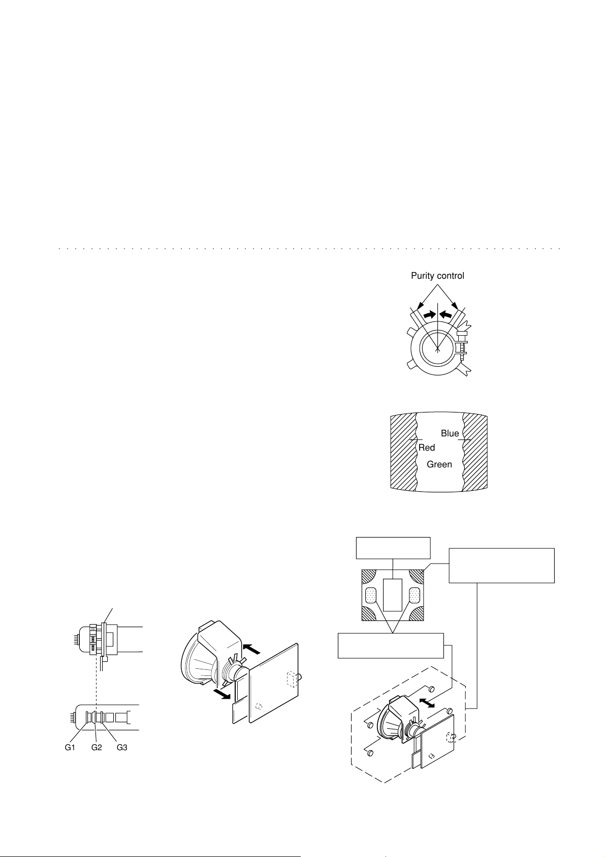
Preparation :
• In order to reduce the influence of geomagnetism on the set's
Purity control
picture tube, face it east or west.
• Switch on the set's power and degauss with the degausser.
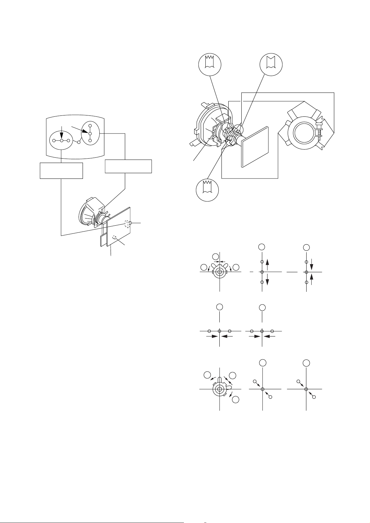
3-1. BEAM LANDING
1. Input a white signal with the pattern generator.
Contrast
Brightness
2. Position neck assy as shown in Fig3-2.
}
normal
Fig. 3-3
3. Set the pattern generator raster signal to a green raster.
4. Move the deflection yoke to the rear and adjust with the
purity control so that the green is at the center and the blue
and the red take up equally sized areas on each side.
(See Figures 3-1 through 3-4.)
5. Move the deflection yoke forward and adjust so that the
Blue
Red
Green
entire screen is green. (See Figure 3-2.)
6. Switch the raster signal to blue, then to red and verify the
condition.
7. When the position of the deflection yoke has been decided,
Fig. 3-4
fasten the deflection yoke with the screws and DY spacers.
8. If the beam does not land correctly in all the corners, use a
magnet to adjust it.
(See Figure 3-5.)
Purity control
corrects this area.
b
a
Disk magnets or rotatable
disk magnets correct these
areas (a-d).
Neck Assy
Behind the G2 edge
G2G1 G3
Fig. 3-1
Fig. 3-2
– 11 –
c
Deflection yoke positioning
corrects these areas.
a
d
d
Fig. 3-5
b
c
KV-AR29M90
RM-993
3-2. CONVERGENCE
Preparation :
• Before starting this adjustment, adjust the focus, horizontal size
and vertical size.
• Receive dot/hatch signal.
• Pic mode: Personal (Pic 90%, Brightness 50%, Colour 50 %,
Hue 50%, Sharpness 50%).
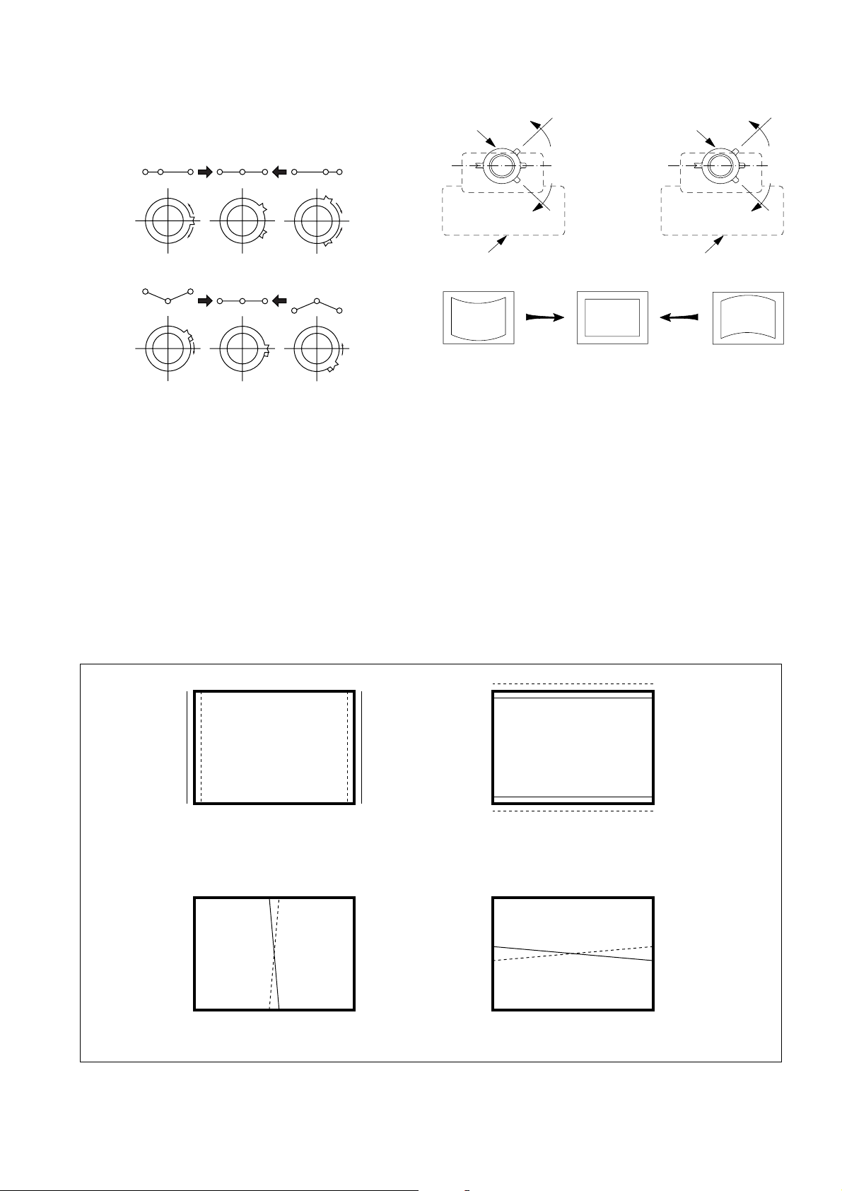
(1) Horizontal and Vertical Static Convergence
Purity
BMC
BMC (Hexapole)
Purity
Center dot
R G B
H. STAT VR
R
G
B
V. STST
Magnet
RV702
H. STAT
RV701
SCREEN (G2)
C6 Board
1. (Moving horizontally), adjust the H.STAT control so that the
red, green and blue dots are on top of each other at the center of
the screen.
2. (Moving vertically), adjust the V.STAT magnet so that the red,
green and blue dots are on top of each other at the center of the
screen.
3. If the H.STAT variable resistor cannot bring the red, green and
blue dots together at the center of the screen, adjust the
horizontal convergence with the H.STAT variable resistor and
the V.STAT magnet in the manner given below.
(In this case, the H.STAT variable resistor and the V.STAT
magnet influence each other, so be sure to perform adjustments
while tracking.)
DY pocket
V.STAT
1 V. S TAT
b b
2 H. STAT VR
RGGBB
3
V.STAT
a
a
B
G
R
a
b
R
a
b
B
G
R
b
– 12 –
b
a
R
G
b
B
B
G
R
4 BMC (Hexapole) Magnet.
Neck assy Neck assy
Blue
Red Blue
Red
VM1 board VM1 board
If the red, green and blue dots are not balanced or aligned, then
use the BMC magnet to adjust in the manner described below.
RG B R G B R GB
KV-AR29M90
RM-993
RB
G
RG
GB
RB
5 Y separation axis correction magnet adjustment.
1. Receive the cross-hatch signal and adjust [PICTURE] to [MIN]
and [BRIGHTNESS] to [STANDARD] .
2. Adjust the Y separation axis correction magnet on the neck
assembly so that the horizontal lines at the top and bottom of
the screen are straight.
(2) Dynamic Convergence Adjustment
Preparation:
• Before starting this adjustment, adjust the horizontal static
convergence and the vertical static convergence
RB
Note
1. The Red and Blue magnets should be equally far from the
horizontal center line.
2. Do not separate the Red and Blue magnets too far. (Less than
8 mm)
B
R
TLH TLV
YCH XCV
RB
R
B
– 13 –
KV-AR29M90
RM-993
TLV Rotate TLV-2 VOL (29”, 34”) on DY
XCV Rotate XCV Adj core on DY
YCH Rotate YCH VOL on DY
TLH Insert TLH Correction Plate to DY Pocket
(Left or Right)
ON DY:
YCH
TLV1
XCV
TLV2
(3) Screen-corner Convergence
ba
a-d : screen-corner
misconvergence
cd
3-3. FOCUS ADJUSTMENT
FOCUS adjustment should be completed before W/B adjustment.
Focus
Screen
FLYBACK TRANSFORMER (T503)
1. Receive digital monoscope pattern.
2. Set "Picture Mode" to "Standard".
3. Set S2801 to mechanical center position.
4. Adjust focus VR so that the center of the screen becomes just
focus.
5. Adjust S2801 when corner focus is unbalance is right and left.
6. Change the receiving signal to white pattern blue back.
7. Confirm Magenta ring is not noticable. Incase magneta ring is
obvious, reset S2801 to mechanical center position and then
adjust FOCUS VR to balance between MAGENTA RING and
FOCUS.
Fix a Permalloy assy corresponding to the misconverged
areas.
a
d
Permalloy assembly
b
c
– 14 –
KV-AR29M90
RM-993
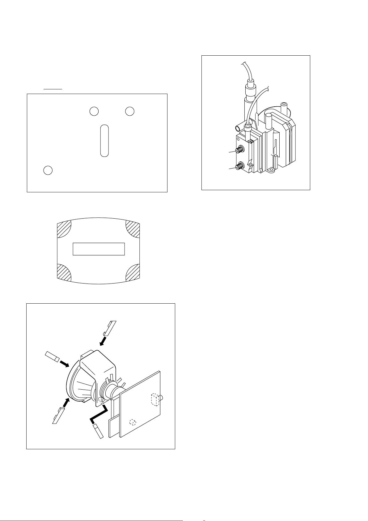
3-4. G2 (SCREEN) AND WHITE BALANCE
ADJUSTMENTS
1. G2 (SCREEN) ADJUSTMENT
1) Set the PICTURE to normal.
2) Put to VIDEO input mode without signals.
3) Connect R, G and B of the C6 board cathode to the
oscilloscope.
4) Adjust BRIGHTNESS to obtain the cathode voltage to the
value below.
5) Adjust G2 (screen) on the FBT until picture shows the point
before cut off.
Cathode setting voltage:
175 V ± 2 (VDC)
0 V
2. WHITE BALANCE ADJUSTMENT
1) Set to Service Mode (Refer Section 4-1: ADJUSTMENTS
WITH COMMANDER).
2) Input white raster signal.
3) Set the PICTURE to minimum.
4) Select GCT (WHB 4) and BCT (WHB 5) with [1] and [4], and
adjust the level with [3] and [6] for the best white balance.
5) Set the PICTURE to maximum.
6) Select GDR (WHB 1) and BDR (WHB 2) with [1] and [4],
and adjust the level with [3] and [6] for the best white
balance.
7) Write into the memory by pressing [MUTING] then [0].
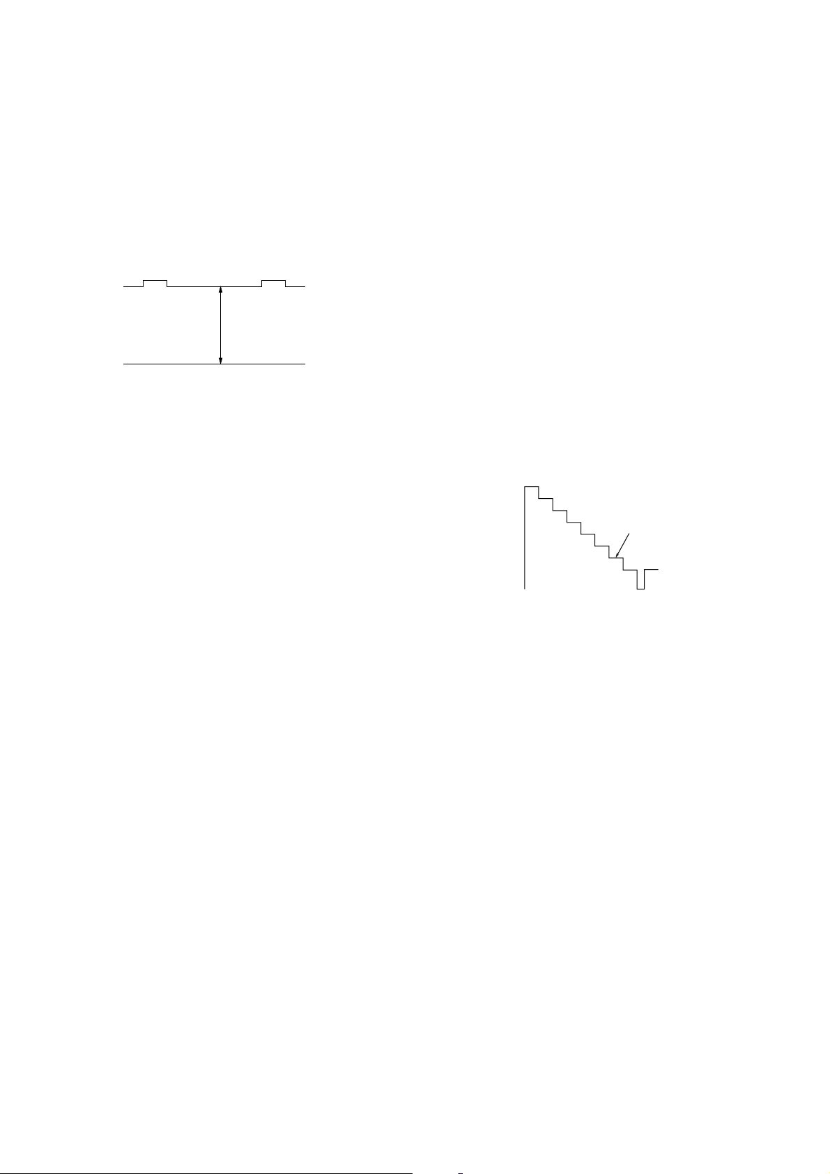
3. SUB BRIGHT ADJUSTMENT
1) Set to service mode.
2) Input a staircase signal of black to white from the pattern
generator.
3) BRIGHTNESS ....50%.
PICTURE ............MINIMUM
4) Select SBR (WHB7) with [1] and [4], and adjust SBR
(WHB7) level with [3] and [6] so that the second stripe from
the right is dimly lit.
White
second from the right
Black
– 15 –
KV-AR29M90
RM-993
SECTION 4
CIRCUIT ADJUSTMENTS
4-1. ADJUSTMENTS WITH COMMANDER
Service adjustments to this model can be performed using the
supplied Remote Commander RM-993.
a. ENTERING SERVICE MODE
With the unit on standby
n
[DISPLAY] n 5 n VOL (+) n [POWER]
This operation sequence puts the unit into service mode.
The screen display is :
Device
Name
Suffix No
(OEM Code)
Software version Total Power-On time (hours)
b. METHOD OF CANCELLATION FROM SERVICE
MODE
Set the standby condition (Press [POWER] button on the commander),
then press [POWER] button again, hereupon it becomes TV mode.
c. METHOD OF WRITE INTO MEMORY
1) Set to Service Mode.
2) Press [1] (UP) and [4] (DOWN), to select the adjustment.
4) Press [MUTING] button to indicate WRITE on the screen.
5) Press [0] button to write into memory.
d. MEMORY WRITE CONFIRMATION METHOD
1) After adjustment, pull out the plug from AC outlet, and then
plug into AC outlet again.
2) Turn the power switch ON and set to Service Mode.
3) Call the adjusted items again to confirm adjustments were made.
1, 4 Select the adjustment item.
↓
3, 6 Raise/lower the data value.
↓
Item No
00
1.0C
Item
Name
Data Mode
HPS 1C pGEO
59 7F 000A0602S
Marking of new NVM
PAL,SECAM:50
NTSC :60
[MUTING] Writes.
↓
- Executes the writing.
4-2. ADJUSTMENT METHOD
Item Number 00 of device GEO
This explanation uses H-Position as an example.
1. Select “GEO 00 HPS” with the 1 and 4 buttons.
2. Raise/lower the data with the 3 and 6 buttons.
3. Select the optimum state. (The standard is 1F for PAL
reception.)
4. Write with the [MUTING] button. (The display changes to
WRITE.)
5. Execute the writing with the - button. (The WRITE
display will be changed to red color while excuting, and
back to SERVICE.)
Example on screen display :-
GEO 00
602S 1.0C
GEO 00
602S 1.0C
Write with [MUTING]
GEO 00
602S 1.0C
Write executed with -
1F 50HPS
7F 0 000A59
1F WRITE 50HPS
7F 0 000A59
1F 50HPS
7F 0 000A59
GREEN
Adjusted with 3
and 6 buttons.
GREEN
RED
The WRITE display
then the display
returns to green
SERVICE.
Use the same method for all Items. Use 1 and 4 to select the
adjustment item, use 3 and 6 to adjust, write with [MUTING],
then execute the write with -.
Note :1.In [WRITE], the data for all items are written into
memory together.
2. For adjustment items that have different standard data
between 50Hz or 60Hz, be sure to use the respective
input signal after adjustment.
7, - All the data becomes the values in memory.
8, - All user control goes to the standard state.
5, - Service data initialization (Be sure not to use
usually.)
[MUTING]+ - Write 50Hz adjustment data to 60Hz, or vice
versa.
2, - Copy and write all data.
– 16 –
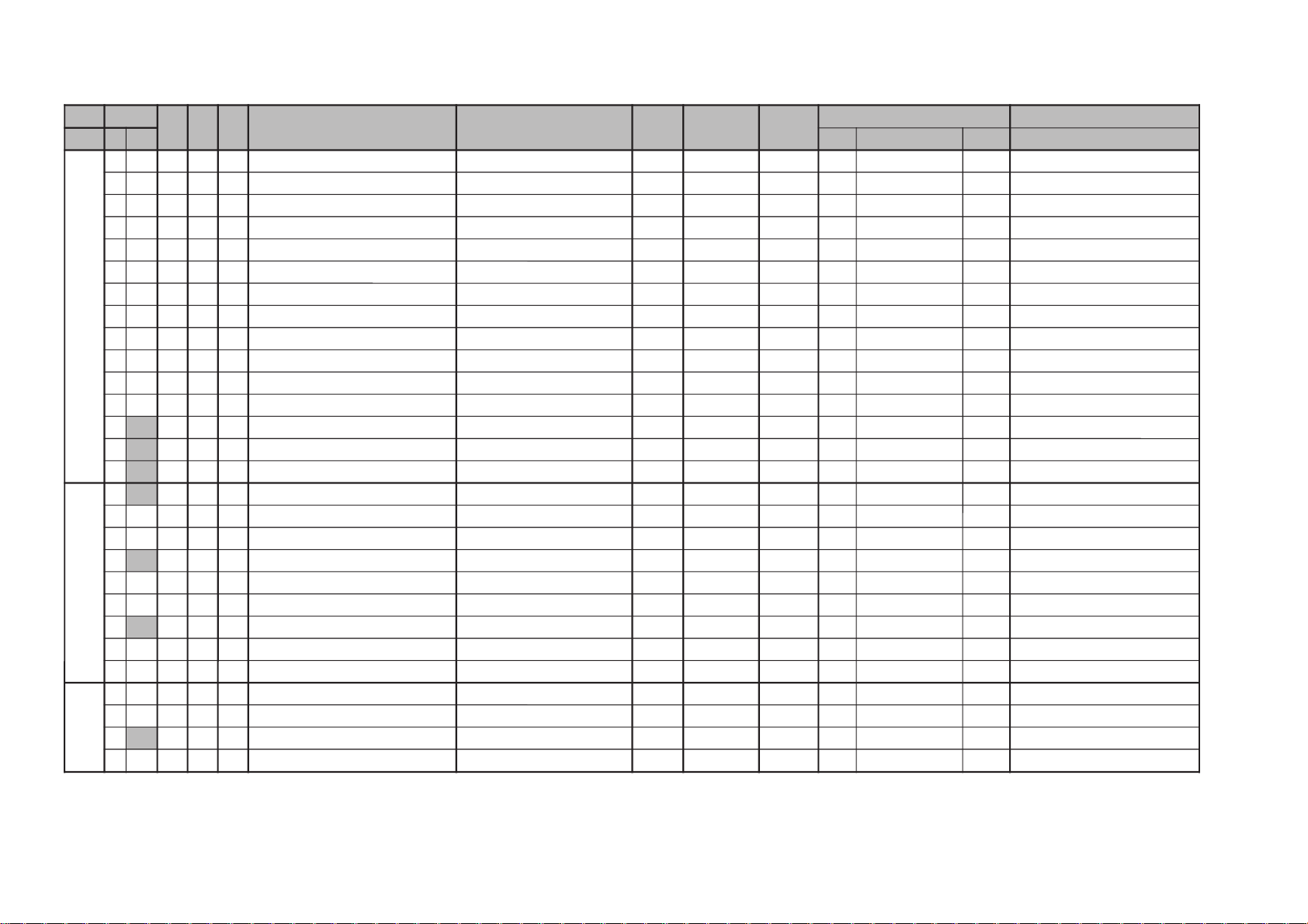
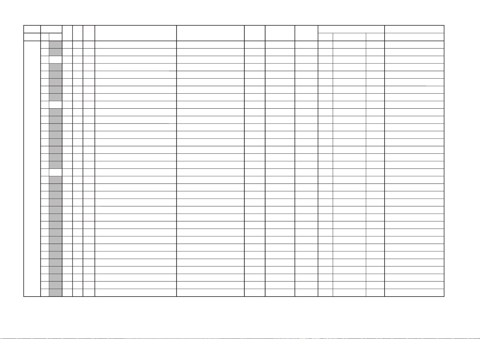
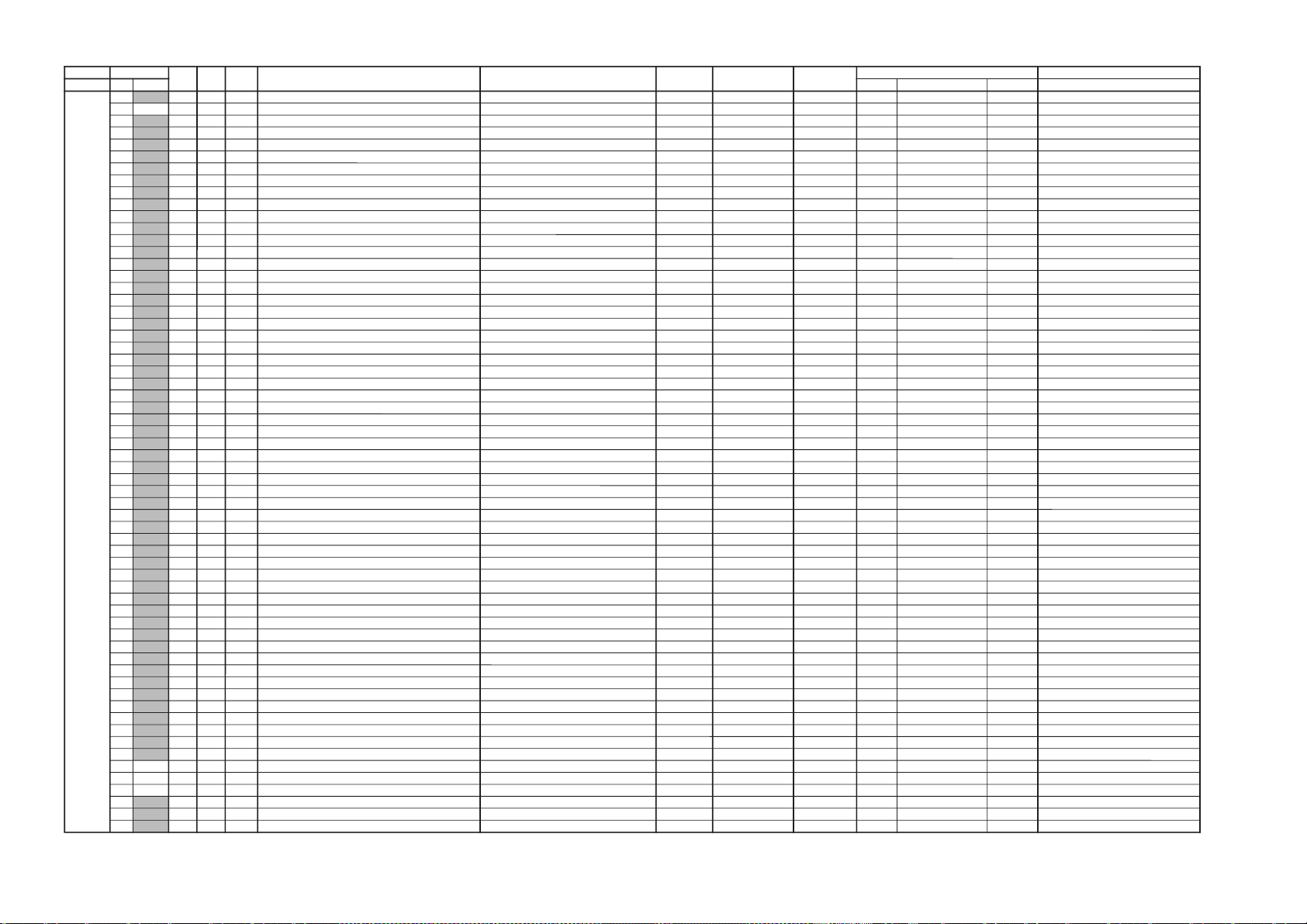
Adjustment Item Table
GVT
ytilanoitcnuF
oN
ceD
laitinI
egnaR
noitcnuF
etoN&elbaT
.oNretsigeR
)egnaRtiB(
emaNeciveD
)sserddAevalS(
sserddAMAR
)egnaRtiB(
sserddAMVN
:skrameR
yrogetaC
.oN
emaN
evalS
buS
tiB
selbatrofatadlaitinI
OEG00SPH0E1F3noitisoPH })06/05(ediW/)06/05(lamroN{srehtO:ORN)2-7(41)H88(S9512AXC)2-7(E96A)17/F6(/)D6/B6(2-7)zH06rof(E1
10ZSH152F3eziSH )06/05(ediW/)06/05(lamroN)2-7(31)2-7(D94A/0A)E4/34(/)DA/0A(2-7lacipyt
20PAP2F1F3pmAniP )06/05(ediW/)06/05(lamroN)2-7(51)2-7(F94A/0A)05/54(/)FA/2A(2-7lacipyt
30TLT37F0muizeparT )06/05(ediW/)06/05(lamroN)4-7(71)4-7(1A4A/0A)25/74(/)1B/4A(4-7lacipyt
40SPV4F1F3noitisoPV )06/05(ediW/)06/05(lamroN)2-7(11)2-7(B94A/0A)C4/14(/)BA/E9(2-7lacipyt
50ZSV5F1F3ezisV )06/05(ediW/)06/05(lamroN)2-7(01)2-7(A94A/0A)B4/04(/)AA/D9(2-7lacipyt
60OCS67F0noitcerroCS )06/05(ediW/)06/05(lamroN)4-7(21)4-7(C94A/0A)D4/24(/)CA/F9(4-7lacipyt
70NLV77F0ytiraeniLV )06/05(ediW/)06/05(lamroN)0-3(21)0-3(C94A/0A)D4/24(/)CA/F9(0-3lacipyt
80WOB87F0woBCFA )06/05(ediW/)06/05(lamroN)4-7(81)4-7(2A4A/0A)35/84(/)2B/5A(4-7lacipyt
90LGA97F0elgnACFA )06/05(ediW/)06/05(lamroN)0-3(81)0-3(2A4A/0A)35/84(/)2B/5A(0-3lacipyt
A0NPU01F1F3niPreppU )06/05(ediW/)06/05(lamroN)2-7(61)2-7(0A4A/0A)15/64(/)0B/3A(2-7lacipyt
B0NPL11F1F3niPrewoL )06/05(ediW/)06/05(lamroN)2-7(A1)2-7(4A4A/0A)55/A4(/)4B/7A(2-7lacipyt
C0
LBH2111 ffo/nogniknalBH srehtO:ORN)1(A1)1(476A371 lacipyt
D0
LBL31B0F0gniknalBHtfeL })06/05(ediW/)06/05(lamroN{srehtO:ORN)4-7(91)4-7(3A6A)27/07(/)E6/C6(4-7)zH06rof(F0
E0
LBR412F0gniknalBHthgiR })06/05(ediW/)06/05(lamroN{srehtO:ORN)0-3(91)0-3(3A6A.)27/07(/)E6/C6(0-3lacipyt
BHW00
RDR052F3evirDR srehto/CIMANYD)2-7(B0)H88(S9512AXC)2-7(E730AAB/0C2-7)CIMANYD-nonrof(A2
10RDG152F3evirDG srehto/CIMANYD)2-7(C0)2-7(F730ABB/1C2-7lacipyt
20RDB252F3evirDB srehto/CIMANYD)2-7(D0)2-7(0830ACB/2C2-7lacipyt
30
TCR37F0ffotuCR srehto/MACES)0-3(90)0-3(2830ADB/3C0-3lacipyt
40TCG47F0ffotuCG srehto/MACES)4-7(A0)2-7(3830AEB/4C4-7lacipyt
50TCB57F0ffotuCB srehto/MACES)0-3(A0)0-3(3830AEB/4C0-3lacipyt
60
NMB651F1ataDmuminiMssenthgirB )2-7(80)2-6(6010A222-6-
70RBS752F3lortnoCssenthgirBbuS )2-7(80)2-7(7010A322-7-
80BPA 803 3#erutciPtnegilletnIrofhctiwSlortnoCthgirBbuS )2-7(80)0-1(7010A320-1-
JAS00XMP083F3ataDmumixaMerutciP ediW/ediW-non)2-7(50)H88(S9512AXC)2-7(5010A02/122-7lacipyt
10UHS17F0lortnoCeuHbuS oediV/VT)2-7(70)2-5(8010A83/422-5lacipyt
20
HSS25F0lortnoCssenprahSbuS oediV/VT)4-7(90)2-7(9010A63/524-7)OEDIVrof(90
30LCS3F1F3lortnoCroloCbuS )srehto/CSTN(EDIW/)srehto/CSTN()2-7(60)2-7(A010A)B3/C3(/)62/73(2-7lacipyt
– 17 –
KV-AR29M90
RM-993
KV-AR29M90
GVTytilanoitcnuF.oN
ceD
laitinIegnaRnoitcnuFetoN&elbaT.oNretsigeR
)egnaRtiB(
emaNeciveD
sserddAevalS
sserddAMAR
)egnaRtiB(
sserddAMVN:skrameR
yrogetaC.oNemaN evalSbuStiBselbatrofatadlaitinI
PV00
THE05F0pmoCTHE zH06/05)0-3(71)H88(S9512AXC)0-3(1A]4A/[0A])25/74(/[1B/4A0-3lacipyt
10
AMG123 )edomDRADNATSnidetatapes(noitcerroCammaG )srehto/CSTN(DTS/)srehto/CSTN(DTS-NON)0-1(D0)0-1(7634A96/A6/76/860-1lacipyt
20GPA201 3#erutciPtnegilletnIrofhctiwSlortnoCammaG )srehto/CSTN(DTS/)srehto/CSTN(DTS-NON)0-1(D0)2(7634A96/A6/76/862 -
30
LDY36F0yaleDY DVD/CSTN/MACES/LAP)0-3(E0)0-3(C634AF3/D3/E3/C30-3)DVD/CSTN/MACESrof80/80/90(
40 TSS413 noitisoPtratSDIMACES CSTN&LAP-DECROF/OTUTA&MACES)4-5(30)4-5(9634AD6/B64-5)CSTN/LAPdecrofrof00(
50 PSS513 noitisoPpotSDIMACES CSTN&LAP-DECROF/OTUTA&MACES)6-7(30)6-7(9634AD6/B66-7)CSTN/LAPdecrofrof30(
60
MLR603 timiLBGR )0-1(30)0-1(D50A380-1lacipyt
70 VLS723OleveLDIMACES CSTN&LAP-DECROF/OTUTA&MACES)0-1(40)0-1(A634AE6/C60-1)CSTN/LAPdecrofrof20(
80FBS822F3OfLLEBMACES CSTN&LAP-DECROF/OTUTA&MACES)2-7(40)2-7(A634AE6/C62-7)CSTN/LAPdecrofrof22(
90 CYD911 ffo/noroloCcimanyD )1(C0)1(660AC81 -
A0 LBA0111 )edomDRADNATStpecxe(gnihctiwSedoMLBA DRADNATStpecxe)1(B0)1(560AB81 )DRADNATSrof00(
B0
HTV1111 gnihctiwShtVnoitceteDLBA )0(B0)0(560AB80 -
C0
0FS2111 ssenprahSrofgnihctiwSOF srehto/CSTN)1(70)1(A534A95/C51 lacipyt
D0 XCD3111 gnihctiwSoitaR.snarTCD )1(80)1(260A881 -
E0
THS4111 hctiwSoitartoohsrevO/-erP srehto/CSTN)0(80)0(B534AA5/D50 lacipyt
F0
WDH5101 hctiwShtdiWesluPevirDH )6(00)6(A50A086 -
01 CFA611 3OlortnoCniaGCFA txeT/oediV/VT)0-1(11)0-1(7A0AA2/92/820-1)TXET/OEDIVrod10/00(
11SOH717 F0noitallicsOH )4-7(E0)4-7(860AE84-7-
21
SSH8101 .peScnySHfoleveLecilS )1(F0)1(960AF81 -
31
SSV9101 .peScnySVfoleveLecilS )0(F0)0(960AF80 -
41
SMH0211 no/ffom/CnoisiVorcaM zH06/05)0(01)0(A9]4A/[0A])B4/04(/[AA/D90 lacipyt
51
VUY1201 LESY )2(00)2(A50A082 -
61 VDC2213 langisonrednuFRdnaoedivrofedomDC ylnooediv)4-5(F0)4-5(5630AB24-5-
71 NOR3211 NOR deziromemton)2(10)2(B50A182 desiromemton
81 NOG4211 NOG deziromemton)1(10)1(B50A181 desiromemton
91
NOB5211 NOB deziromemton)0(10)0(B50A180 desiromemton
A1 NOP6211 NOP deziromemton)7(00)7(A50A087 desiromemton
B1 NXA7211 WSSIXA )CIMANYDrofylno(srehto/CSTN)0(70)0(A010A])B3/C3(/[62/730 -
C1
LSR8201 LESBGR )0(C0)0(660AC80 -
D1
WBV9203 WKLBV )0-1(61)0-1(070A690-1-
E1
PFR0301 PFER )0(41)0(E60A490 -
F1
CMV1303 leveLMV )2-3(30)2-3(D60A382-3-
02 FBC2301 retliFssapdnaBamorhC
12
OTC3301 ffOparTamorhC
RM-993
– 18 –

GVTytilanoitcnuF.oN
ceD
laitinIegnaRnoitcnuFetoN&elbaT.oNretsigeR
)egnaRtiB(
emaNeciveD
sserddAevalS
sserddAMAR
)egnaRtiB(
sserddAMVN:skrameR
yrogetaC.oNemaN evalSbuStiBselbatrofatadlaitinI
2PA00
SBB03F0gnitteSleveLtsooBssaB 0A444-7
10
BCB101 lortnoCssaBbuSroftcelestuctsooB 0A542
20
SBS203 gnitteSleveLssaBbuS 0A540-1
30
TCB301 lortnoCelberTbuSroftcelestuctsooB 0A642
40
STS403 gnitteSleveLelberTbuS 0A640-1
50
LGA503 gnitteSleveLCGA 0A842-3
60
WSB601 hctiwSFFO/NOtsooBssaB 0A443
70
SAB70F1lortnocedomdnuosssaB tfos/amard/anyd 6A}B7/87/57{}48/18/E7{0-4
80
ERT80F1lortnocedomdnuoselberT tfos/amard/anyd 6A}C7/97/67{}58/28/F7{0-4
90
EBB90FFlortnoCedomdnuoSEBB tfos/amard/anyd 6A}D7/A7/77{}68/38/08{0-7
PSM00
TSW051FFdlohserhToeretSG/W )H48(D5143PSM5610A060-7-
10
TBW1CEFFdlohserhTlaugniliBG/W 6610A160-7-
20
LLW25FFdlohserhTlaruanoMG/W 7610A260-7-
30
CAW31F0tnuoCtnemeergAG/W )0-3(8610A360-3-
40
LDW403FFyaleDhcraeSG/W 9610A460-7-
50
LDN502FFyaleDhcraeSMACIN A610A560-7-
60
LDS601FFyaleDdaeRsutatsoeretS B610A660-7-
70
CGA711 tnatsnoC/otuAhctiwSCGA )7(BB00)7(6110A867 -
80
LER882F3edoMtnatsnoCtaniaGCGA )1-6(BB00)1-6(6110A861-6-
90
MRC901 ffo/nognitumreirraC )9(BB00)9(5110A761 -
A0
OCA0111 ffo/notuokcolCoiduA )5(3800)5(A110A965 -
B0
PF11B1F7metsysM-nonrofelacserPMF )8-41(E000F230AA60-6-
C0
MPF2123F7metsysMrofelacserPMF )8-41(E0000330AB60-6-
D0
HF3163F7VEDHrofelacserPMF )8-41(E0001330AC60-6-
E0
MHF4156F7MdnaVEDHrofelacserPMF )8-41(E0002330AD60-6-
F0
PGW51C1F7elacserPG/W )8-41(E0003330AE60-6-
01
PIN61F7F7elacserPMACIN )8-41(01007410AF60-6-
11
RRE7105FFdlohserhThctiwsMFotuA )3-01(12004710A070-7-
21
LOV81D6FFh0ff7oth007niagrekaepSduoL )4-51(00000634A260-7-
– 19 –
KV-AR29M90
RM-993
KV-AR29M90
GVTytilanoitcnuF.oN
ceD
laitinIegnaRnoitcnuFetoN&elbaT.oNretsigeR
)egnaRtiB(
emaNeciveD
sserddAevalS
sserddAMAR
)egnaRtiB(
sserddAMVN:skrameR
yrogetaC.oNemaN evalSbuStiBselbatrofatadlaitinI
PIP00
ORP001 elbanEedoMnacSevieergorP )H6D(X8829ADS)3-6(2914AC13-6
10DER101 edoMelbuoDdaeR
20
IEF203 tceleSdleiF
30
SPH353FFnoitisoPerutciPlatnoziroH
40
SPV4B1FFnoitisoPerutciPlacitreV
50
PFH50F0gninoitisoPeniFlatnoziroH
60
PFV60F0gninoitisoPeniFlacitreV
70
SID703 dradnatsyalpsiD
80
SOH803 eziSlatnoziroH
90
SEV903 eziSlacitreV
A0
SPF0103 dradnatStneraPecroF
B0
MZH1107 mooZlatnoziroH
C0
PSV2101 noitcudeResioNeluPcnySlacitreV
D0
LDV310 F1yaleDesluPcnySlacitreV
E0
HRF4157 latnoziroHhtdiWemarF
F0
VWF5123 lacitreVhtdiWemarF
01
DRV6101 noitcudeR
11
KBV7101 gniknalBlacitreV
21
YLD810F yaleDtceleS
31
RCP9101 noitcerroCnoitisoP
41
MGA0233 edoMCGA
51
CGA126F eulaVlortnoCniaGcitamotuA
61
BVC2203 tceleSSBVC
71
DPC3213 noitaruDGNIPMALC
81
TPC4213 tratsesluPGNIPMALC
91
MUL5203 tesffoecnanimuL
A1
LLP6203 tnatsnoCemiTLLPtresnI
B1
DCY722F yaleDC/Y
C1
RSN8203 llPtresnirofnoitcudeResioN
D1
PSL9201 deepSnoitacifitnedIdradnatS
E1
LIK0303 dlohserTrelliKroloC
F1
PGB1301 noitisoPetaGtsruB
02
CES2301 levelnoitacifitnedIMACES
12
MED3313 noitceleswsahpmeeD
22
AMC4303 htiwdnaBamorhC
32
CFI5323 retliFnoitasnepmoCFI
42
EUH630 F1euH
52
ACS737 F1tnemtsujdAreirracbuSroloC
62
NOC830F tnemtsujdAtsartnoC
72
RLB930F lennahCdeRleveLgniknalB
82
TRB040F tnemtsujdAssenthgirB
92
GLB140F lennahCneerGleveLgniknalB
A2
RIB2401 lennahCdeRnoisrevnIgniknalB
B2
BIB3401 lennahCeulBnoisrevnIgniknalB
C2
BLB440F lennahceulblevelgniknalB
D2
TNI5401 lavretnIhserfeR
E2
RKP64F4FFlennahCdeRleveLkaeP
F2
GKP74F4FFlennahCneerGleveLkaeP
03
BKP84F4FFlennahCeulBleveLkaeP
13
YRF94AF YroloCemarF
23
TUO0511 tamroFtuptuO
33
URF150F UroloCemarF
43
VRF250F VroloCemarF
53
TAS357F tnemtsujdAnoitarapeSroloC
63
KPY4577 tnemtsujdAkaePY
73
OCY550F elbanEgniroCY
83LAP6533 levelDILAP
93VOP7507 lacitreVtesffOnoitisoP
A3HOP850 F1latnoziroHtesffOnoitisoP
B3
HSV950 F1knirhSlacitreV 1A14A920-7-
C3
HSH060 F1knirhSH 2A14AA20-7-
D3
LPC1613 htgneLesluPGNIPMALC )0-2(5914AF10-2-
RM-993
– 20 –
GVTytilanoitcnuF.oN
ceD
laitinIegnaRnoitcnuFetoN&elbaT.oNretsigeR
)egnaRtiB(
emaNeciveD
sserddAevalS
sserddAMAR
)egnaRtiB(
sserddAMVN:skrameR
yrogetaC.oNemaN evalSbuStiBselbatrofatadlaitinI
TCY00
UHS0F0F1tnemtsujdAeuHbuS oediV/VT)HA8(QA3612AXC
10
GNP111 htdiWetaGCSTN/LAP
20
INP201 WSytivitisneSCSTN/LAP
30LCS37F0lortnoCroloCbuS oediV/VT*06/05
40TCS48F0lortnoCtsartnoCbuS oediV/VT*06/05
50
0FS523 gnignahCycneuqerFretneCssenprahS
60
QES633 citsiretcarahCrezilauqEssenprahS
70
GHS75F0lortnoCniaGssenprahS DVD/oediV/VT*06/05
80LOY8F1F3lortnoCleveLtuptuO-Y
90
PSB903 gnignahCtnioPtratShctertSkcalB
A0LOC01F1F3lortnoCleveLtuptuOrC/bC
B0
RCD1103 tnemtsujdAoitaRnoitarotseRCD
C0
0FB2113 tnemtsujdA0FFQT/FPB
D0
QFB3123 tnemtsujdAQFQT/FPB
E0
WSF4111 hctiwSFQT/FPB
F0
TDS5111 hctiwSparTelbuoDMACES
01
FPL6111 hctiwSFPLrC/bC/Y
11
LDY716 F0tnemtsujdAemiTLD-Y DVD/tupni-S/oediV/VT
21
TMC8101 hctiwSetuMtuptuOrC/bC
31
10B917 F0)etuorniam(tnemtsujdAtesffObC
41
1OR027 F0tnemtsujdAtesffOrC
51
FDC1207 hctiwSycneuqerFnwoDtnuoCV langisonrofzH05decrof
61
MDC2203 hctiwSegduJnwoDtnuoCV
71
CFA3203 hctiwSytivitisneSCFA DVD/oediV)/VT(
81
MVM4211 ksaMCFA+ksaMnoisivorcaM
91
YRS527 F0tnemtsujdAkcalBY-RMACES
A1
YBS621 F0tnemtsujdAkcalBY-BMACES
B1
LEB7223 gnihctiwSFPH/LLEBMACES
C1
FLB8201 tnemtsujdA0fLLEB
D1
IVS9201 hctiwSDI-VMACES
E1
PGS0303 tnemtsujdAnoitisoPetaGMACES
F1
DIS1311 hctiwSytivitisneSMACES MACEStpecxe
02
HIS2301 hctiwSnoitibihnIMACES
12
PTS3301 sulpLAProfputeSleveLkcalBY
22
WSA4311 WSedomtcelesoediVotuA
32
HSW5303 noitcuderesionrofpetSniaGssenprahS
42
OCW6303 noitcuderesionrofpetSleveLtuptuOrC/bC
52
2BC737 F0)tupni2rCbCY(tnemtsujdatesffo2bC
62
2RC837 F0)tupni2rCbCY(tnemtsujdatesffo2rC
72
HPH9301 hctiwsesahptuptuOSH
82
HPV0401 esahptuptuoPVrofhctiwS
92
MCN1401 BMOCCSTN
– 21 –
KV-AR29M90
RM-993
KV-AR29M90
GVTytilanoitcnuF.oN
ceD
laitinIegnaRnoitcnuFetoN&elbaT.oNretsigeR
)egnaRtiB(
emaNeciveD
sserddAevalS
sserddAMAR
)egnaRtiB(
sserddAMVN:skrameR
yrogetaC.oNemaN evalSbuStiBselbatrofatadlaitinI
ET00
0RN01070RN srehtO/CSTN)HA8(QA3612AXC
10
0CT140F0gniroCET srehtO/CSTN
20
0GT25070niaGET srehtO/CSTN
30
HTS30010ssapybET:1ssapybETdecroF
40
FOC40010)215(FFO:1FFOtnenopmoCroloC
50
FOY50010FFO:1FFOtnenopmoCecnanimuL
60
RJV600302PS:32PS:21PS:1NO:0lortnocrettijV
70
FOT70010FFOET:1FFOET
80
FOD80010FFORNtoD:1FFORNtoD
90
FOF91010FFOFPL:1FFOFPLET
A0
HTC010010FFO:1FFOETroloC
B0
LSP112030noitceleSretemaraPET
C0
PLC2180F0leveLpmalCtupnI
D0
2LC3180F0leveLpmalCtuptuO
E0
1AL4100F0)etihW,+(niaGdnepedleveL
F0
2AL5110F0)kcalB,+(niaGdnepedleveL
01
3AL61F0F0)etihW,-(niaGdnepedleveL
11
4AL7110F0)kcalB,-(niaGdnepedleveL
21
WRC814070oitarnoitasnepmoCC/YET
31
DCY913070tnemtsujdayaledtuptuoC/YET
RN00
OMD00010)edoMomeD=1(FFO/NOedoMomeDRN
20
HHT2F0F1noitceridlatnozirohrofleveldlohserhTesioNfotesffO
30
LLB370F0leveLkcalBrofnoitcetedleveLfotesffO
40
TSC470F0leveLroloCrofnoitcetedleveLfotesffO
50
CHT570F0dlohserhTnoitceteDegdEfotesffO
60
FRN600100=knaRsyawla0RN
70
GID70010)nIlatigiD=1(nIlatigiDroniD/A
TXT00
HXT003 noitisoPlatnoziroHtxeteleT )0-1(01)H85(1625AAS)0-1(694A850-1-
10
VXT103 noitisoPlacitreVtxeteleT )4-5(01)4-5(694A854-5-
EJP00
EJP001 )lortnoCecivreSenignE-JP( )HA6(xxxxPXC
MPO00HSO0D0F3noitisoPHDSO csiM-noitpO1F1)H06(790057PXC)2-7(B710A722-7-
10
MOC123 )D3:3,latigiD:2,CSTN:1,enoN:0(noitceleSbmoC )6-7(D430A056-7-
20
CPA211 hctiwSCPA )5(C430AF45 -
30
YST303 sySVTotuAtasySVT )3-4(C430AF43-4-
40
TUM401 etuMlangisoN )0(C430AF40 -
50
MFA511 hctiwsMFotuA )1(C430AF41 -
60
BFR603 lortnoCFPB-C )4-5(D430A054-5-
70OVT727 tesffoelgnA-VottliT )0-2(D430A050-2-
80
LBD801 noitcnuFkcabeulBelbasiD )2(C430AF42 -
90
OSS913 )x8:3,x6:2,x4:1,ffO:0(noitpOhcraeSdeepS )6-7(C430AF46-7-
A0
HCS011 F7noitidnoCgnippihSrofnoitceleSHC ylnosledomCSTN )6-0(7830AD30-6-
B0
ACS1111 noitidnocgnippihsrofnoitcelesriA/elbaC ylnosledomCSTN )7(7830AD37 -
C0
ROP2101 TCYmorFnoitceteDteseRnorewoP )3(D430A053 -
D0
CRN313 FFETDrofretnuoCteD-N
BPO00
1PO0FFFF)wolebees(1stiBlanoitpO stiB-noitpO)H06(790057PXCE40AD20-7-
10
2PO176FF)wolebees(2stiBlanoitpO F40AE20-7-
20
3PO213FF)wolebees(3stiBlanoitpO 050AF20-7-
30
4PO379FF)wolebees(4stiBlanoitpO 150A030-7-
RM-993
– 22 –
NOTE
•
shaded items are fixed data.
• Standard data listed on the Adjustment Item Table are reference values, therefore it may be different for each model and for each mode.
• Note for Different Data Those are the standard data values written on the microprocessor. Therefore, the data values of the modes and stored respectively in the memory.
In case of a device replacement, adjustment by rewriting the data value is necessary for some items.

ITEM INFORMATION
No. OPB0 OP1
Item
KV-AR29M90
(APPLICABLE FOR XF-L(21" & 14") MODELS ONLY.
No. OPB1 OP2
Item
KV-AR29M90
AV Input 00 = no AV Input 01 = 1 AV Input
DVD Input Effective only when "AV Input" is set to 3 AV Input
PIP 4 PIP 4 0 = disabled, 1 = enabled
No. OPB2 OP3
Item
KV-AR29M90
XTAL 4.43
1
TOP
1
Initial menu
1
XTAL 3.58
1
NICAM
1
AP2
1
SECAM
1
HDEV
1
2nd. Lang
1
Thai Bil
0
B/G
1
PIP 4
1
10 = 2 AV Input 11 = 3 AV Input
Auto PIC
1
A-TVsys
1
US ST
0
I
1
DVD Input
1
DTE
0
D/K
1
AV Input
Forced 50/60
0
KV-AR29M90
M
1
11
2
Colour SW
*
1
RM-993
Initial Menu Initial Menu Setup 0 = disabled, 1 = enabled
AP2 Auto Processor Selection 0 = AP, 1 = AP2.
Auto PIC
*3
A-TVsys Auto TV System in Auto Program0 = disabled, 1 = enabled
*
US ST
DTE DTE Model Selection 0 = Non DTE, 1 = DTE
Forced 50/60 Forced to 50/60 Hz during no signal condition 0=60Hz, 1=50Hz
Color SW
Note:*1 - For XA21/XH29 Models Only
No. OPB3 *OP4
*2
- For XA34/29/25 Models Only
*3
- For PNC3, the enables are from service item APG and APB.
Item
KV-AR29M90
*2
PNC2
0
Korean ST
0
Auto Picture Improvement 0 = off PNC1/PNC2
1 = activate PNC1/PNC2
USA Stereo 0 = disabled, 1 = enabled
Color Data Selection in Dynamic Mode 0 = 65 (No PIP), 1 = 57 (PIP)
Vid NTSC3.58
0
Wide
0
Video3
0
Chinese(multi mdl)
1
Arabic/C.Chinese
1
Thai/Korean
1
APPLICABLE TO XS ONLY - Sub Language Selection (Bit 0 - Bit 2)
Korean Stereo* Korean Stereo 0 = disabled, 1 = enabled
2
PNC2*
Enable switch of PNC2 0 = disable, 1 = enable
Video NTSC3.58* Video Color System 0 = Multi System, 1 = Single System (NTSC3.58)
Wide Enable wide mode 0 = disable, 1 = enable
Note : *APPLICABLE FOR NTSC MODELS ONLY
– 23 –
KV-AR29M90
VY
RM-993
4-3. ADJUSTMENT FOR NON DIGITAL TEXTURE
ENHANCER (DTE) MODEL
(not used for this model)
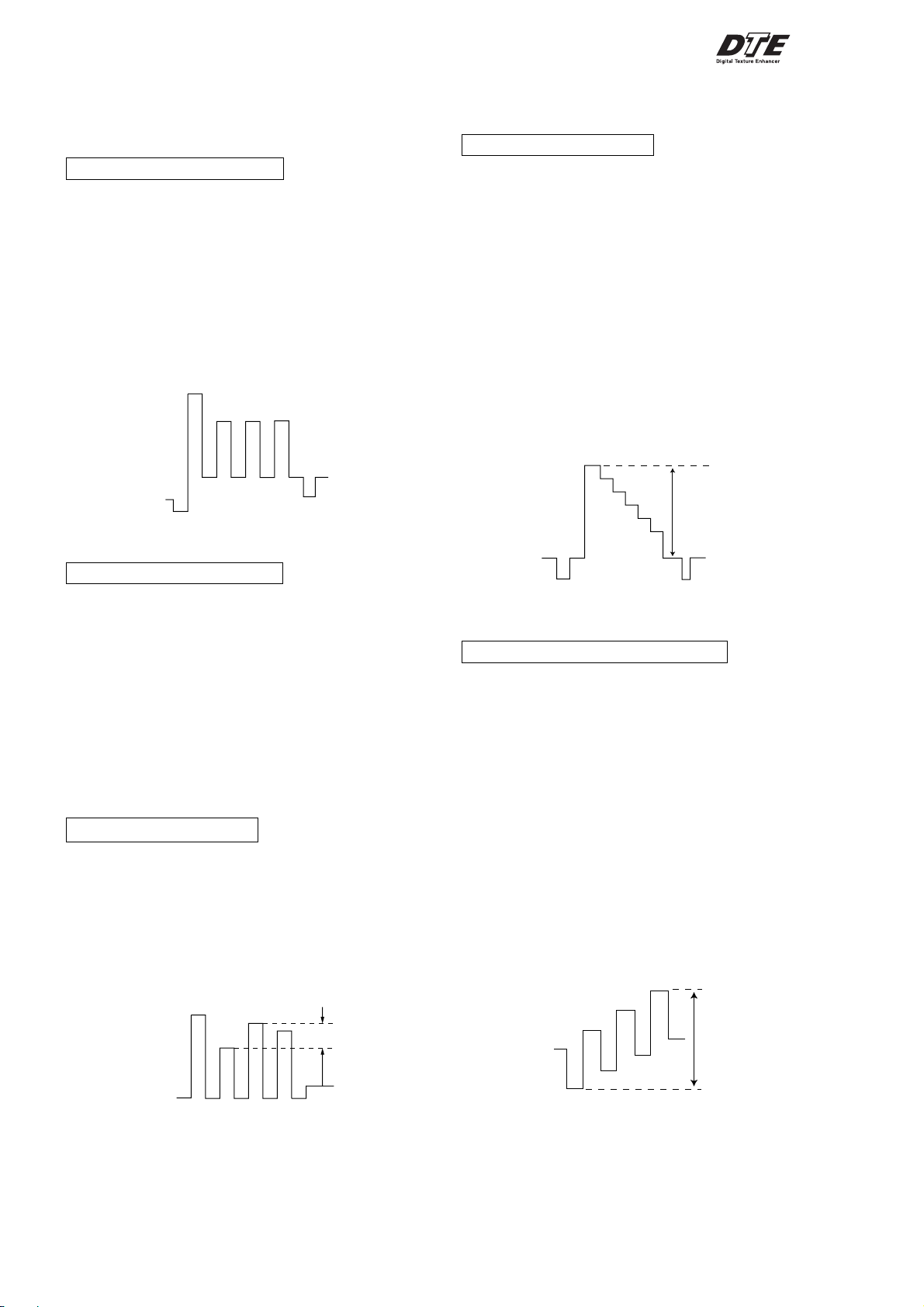
SUB COLOR ADJUSTMENT
1. Select Video.
2. Input PAL Color Bar
3. Set to following condition PICTURE 100%, BRIGHTNESS
50%, Color 50%.
4. Connect an oscilloscope to pin 1 (BOUT) of CN305, A Board.
5. Set the service mode and select SAJ 3 ‘SCL’ with 1 and 4 of
the commander then adjust the VB2=VB3=VB4 3 and 6.
6. Press
7. Input NTSC Color Bar to set and repeat items (3 to 7).
8. Select "WIDE" mode, write the "SAME DATA- 3 STEPS" for
[MUTING] → - of the commander to write the data.
both PAL and NTSC Color Bar input.
VB1
VB2 VB3
VB2 = VB3 = VB4
VB2 = VB3 = VB4 (Difference is within 70mV)
VB4
4-4. ADJUSTMENT FOR DIGITAL TEXTURE
ENHANCER (DTE) MODEL
Y LEVEL ADJUSTMENT
1. Select Video.
2. Input PAL Color Bar to TV set (white reference 100%).
3. Set the following condition:
DTE : ON
Picture Mode : Dynamic
4. Connect an oscilloscope to pin 1 (CV/Y in) of CN106, A
Board.
5. Set to Service Mode and YCT 08 ‘YOL’ with 1 and 4 of the
commander then adjust to VY within spec with 3 and 6.
6. Then press
7. Select RF.
8. Repeat item 2 to 4.
9. Set to Service Mode and YCT 04 ‘SCT’ with 1 and 4 of the
commander then adjust to VY within spec with 3 to 6.
10. Copy SCT data to NTSC (RF).
SCT Setting (Video Mode) : 07h (NTSC & PAL)
[MUTING] → - to write the data.
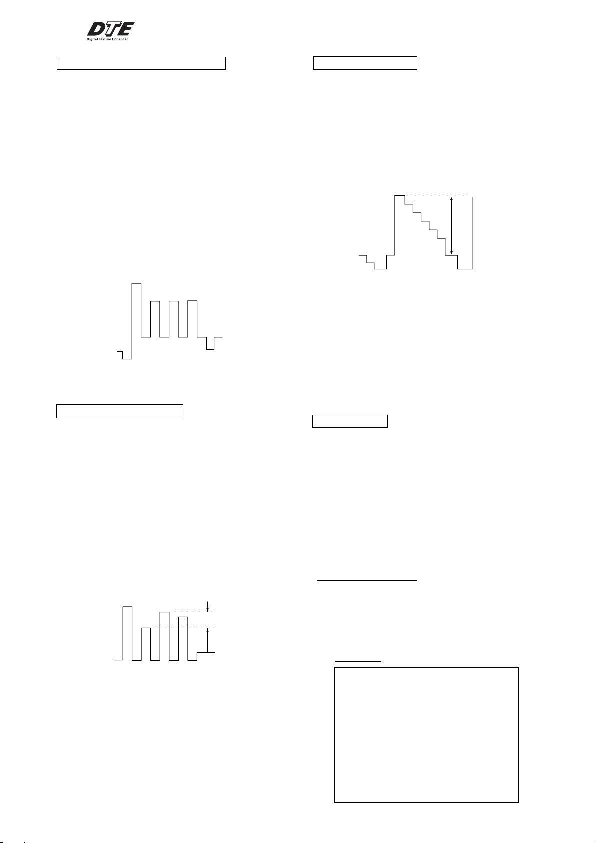
SUB COLOR ADJUSTMENT
1. Select Video.
2. Input PAL Color Bar
3. Set to following condition PICTURE 100%, BRIGHTNESS
50%, Color 50%.
4. Connect an oscilloscope to pin 1 (BOUT) of CN305, A Board.
5. Set the service mode and select SAJ 3 ‘SCL’ with 1 and 4 of
the commander then adjust the VB2=VB3=VB4 3 and 6.
6. Press
[MUTING] → - of the commander to write the data.
7. Add 6 steps and save the data.
8. Input NTSC Color Bar to TV set and repeat items 3 to 7.
9. Select "WIDE" mode, write the "SAME DATA- 3 STEPS" for
both PAL and NTSC Color Bar input.
SUB HUE ADJUSTMENT
1. Select Video 1.
2. Input a NTSC 3.58 color-bar, video into Video 1.
3. Set the following condition:
PICTURE 100%, BRIGHTNESS 50%, COLOR 50%
4. Connect an oscilloscope to pin 1 (B OUT) of CN305, A board.
5. Select SAJ 1 "SHU" with 1 and 4 of the commander by
setting to Service Mode and adjust to VB1=VB2=VB3=VB4
with 3 and 6.
VB1
VB2
VB3
VB4
± 110mV
SPEC: VY : 1.2 Vpp ± 0.05m Vpp
SUB COLOR (YCT) ADJUSTMENT
1. Select Video.
2. Input NTSC Color Bar.
3. Set the following condition:
DTE : ON
Picture Mode : Dynamic
NTSC 75% Color Bar
4. Connect an oscilloscope to pin 2 (B-Y in) of CN303, A Board.
5. Set to Service Mode and YCT 0A ‘COL’ with 1 and 4 of the
commander then adjust to VB within spec with 3 and 6.
6. Then press
7. Select RF.
8. Repeat item no 2 to 4.
9. Set to Service Mode and YCT 03 ‘COL’ with 1 and 4 of the
commander then adjust the waveform within spec with 3 and
6.
10. Then press
11. Input PAL Color Bar (75%) and repeat item no 8 to 10.
[MUTING] → - to write the data.
[MUTING] → - to write the data.
VB
VB1 = VB2 = VB3 = VB4
The highest level of VB1,VB2,VB3,VB4 must be aligned at
the same line. Ideal difference level between VB2 and VB3
should be within ± 110mV.
6. Press [MUTING] → - of the commander to write the data.
7. Adjust SAJ 1 "SHU" as step 3 to 6 when receiving TV mode.
SPEC :
VIDEO : VB = 0.931 Vpp ± 50 mVpp
RF : VB = 0.931 Vpp ± 50 mVpp
– 24 –
KV-AR29M90
RM-993
SUB COLOR (YCJ) ADJUSTMENT
1. Select Video.
2. Input PAL Color Bar to TV set.
3. Set the following condition:
Pic: 100%, Col: 50%, Brightness: 50%, DTE: OFF
4. Connect an oscilloscope to pin 2 (B output) of CN305, A
Board.
5. Set to Service Mode and SAJ 03 ‘SCL’ with 1 and 4 of the
commander then adjust to VB2 = VB3 = VB4 = with 3 and
6.
6. Then press
[MUTING] → - to write the data.
7. Add offset steps and save the data.
Offset: 25... 0
29... 0
34... 0
8. Input NTSC color bar to TV set and repeat item no 3 to 7.
10. Select "WIDE" mode, write the "SAME DATA - 3 STEPS" for
both PAL and NTSC input.
VB1
VB2 VB3
VB2 = VB3 = VB4
VB4
VB2 = VB3 = VB4 (Difference is within 70mV)
SUB HUE ADJUSTMENT
1. Select Video.
2. Input NTSC 3.58 Color Bar to TV Set.
3. Set the following condition:
Pic: 100%, Col: 50%, Brightness: 50%, DTE: OFF
4. Connect an oscilloscope to pin 1 (B output) of CN305, A
Board.
5. Set to Service Mode and YCT 00 ‘SHU’ with 1 and 4 of the
commander then adjust to VB1 = VB2 = VB3 = VB4 = with 3
and 6.
6. Then press
7. Select RF.
8. Input NTSC 3.58 and repeat item no 3 and 6.
The highest level of VB1, VB2, VB3, VB4 must be
aligned at the same time.
Ideal difference level between VB2 and VB3 should
be within ± 110 mVpp.
[MUTING] → - to write the data.
VB1
VB3
VB4
VB2
VB1 = VB2 = VB3 = VB4
110mV
PMX ADJUSTMENT
1. Select Video (Wide mode: OFF).
2. Input PAL Color Bar to TV set.
3. Set the following condition:
Pic: 100%, Col: 50%, Brightness: 50%, DTE: OFF
4. Connect an oscilloscope to pin 3 (R output) of CN305, A
Board.
5. Set to Service Mode and SAJ 00 ‘PMX’ with 1 and 4 of the
commander then adjust to VR within spec with 3 and 6.
6. Then press
[MUTING] → - to write the data.
7. Select "Wide" mode, write the "SAME DATA- 5 STEPS".
VR
VR = 2.35 Vpp
(Difference is within 50 mVpp)
VP 06 RLM : 03H
17 R ON : 01H
18 G ON : 00H
19 B ON : 00H
After adjustment, these adjustment parameters must be recovered
to the original condition.
4-5. DISPLAY POSITION ADJUSTMENT
(not used for this model)
PIP POSITION
1. Input a PAL color-bar.
2. Press PIP button of the remote commander to set the PIP
picture.
3. Set to Service Mode.
4. Use 1 and 4 of the remote commander to select PIP 03 “HPS”
and use 3 and 6 to set data “15”.
5. Select PIP 04 “VPS” to set data “2E”.
6. Press
[MUTING] → - of the remote commander to write the
data.
7. Use the screen display menu changing the PIP position to check
the PIP position.
4-6. DEFLECTION ADJUSTMENT
NORMAL MODE (50Hz)
1. Set Video Mode.
2. Using the 1 and 4 button, select category GEO
(Service Mode).
3. Raise/lower the data using the 3 and 6 buttons.
Select and adjust the following items to obtain optimum
image.
Service Item
GEO : 00 HPS H POSITION
01 HSZ H SIZE
02 PAP PIN AMP
03 TLT TILT
04 VPS V POSITION
05 VSZ V SIZE
06 SCO S CORRECTION
07 VLN V LINEARITY
08 BOW AFC BOW
09 AGL AFC ANGLE
0A UPN UPPER CORNER PIN
0B LPN LOWER CORNER PIN
– 25 –
KV-AR29M90
RM-993
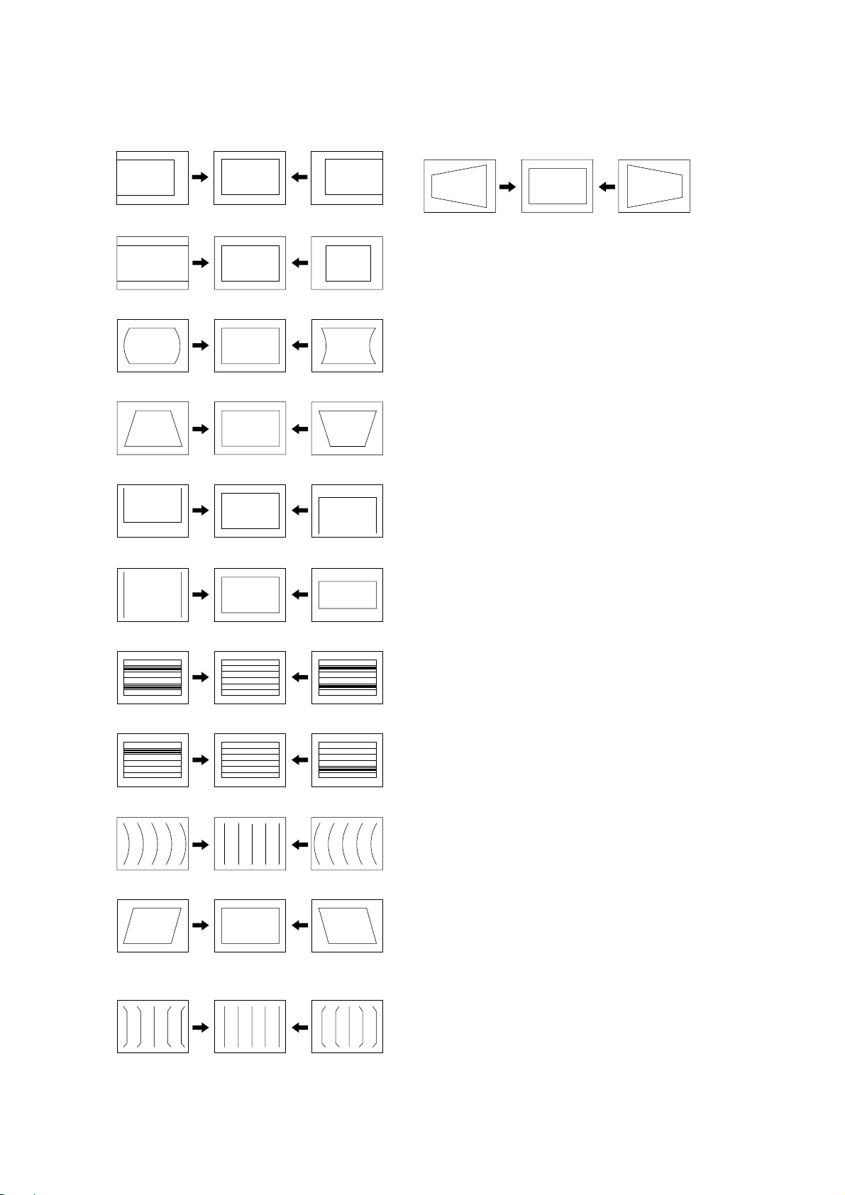
4-7. PICTURE DISTORTION ADJUSTMENT (1)
Item Number 00 – 0B
GEO 0 HPS (H POSITION)
GEO 1 HSZ ( H SIZE)
GEO 2 PAP (PIN AMP)
GEO 3 TLT (TRAPEZIUM)
GEO 4 VPS (V POSITION)
PICTURE DISTORTION ADJUSTMENT (2)
H-TRAPEZOID (DAC 4 HTR)
GEO 5
GEO 6
GEO 7
GEO 8
GEO 9
VSZ (V SIZE)
SCO (VERTICAL S-Correction)
VLN (V LINEARITY)
BOW (AFC. BOW)
AGL (AFC. ANGLE)
GEO 0A
GEO 0B
UPN (UPPER CORNER PIN)
LPN (LOWER CORNER PIN)
– 26 –
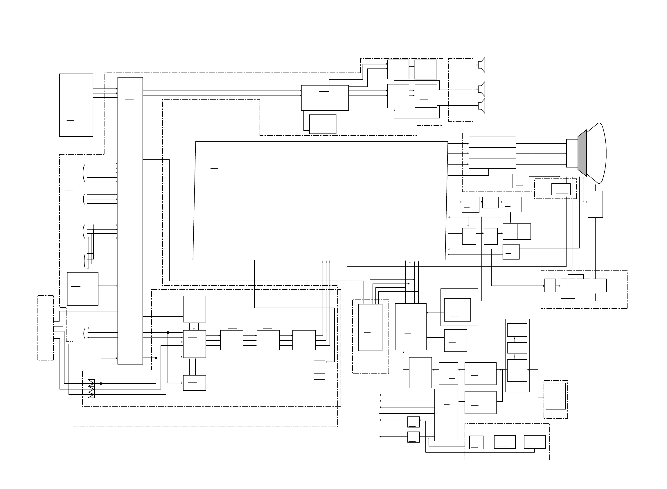
5-1. BLOCK DIAGRAM
SECTION 5
DIAGRAMS
KV-AR29M90
RM-993
KV-AR29M90
RM-993
J
(DVD,3D
TERMINAL)
R
L
V
U
V
MAIN.TUVF
with
STEREO
DECODER
(MSP3415)
CN1407
TV.V In
TV.L In
TV.R In
47
46
45
<slave: 86H>
TU101
BTF-WG441
<slave: C0H>
V1.V In
1
V1.L In
2
V1.R In
VIDEO IN 1
JACK BLACK
J1402
PIN 12P
VIDEO IN 2
VIDEO IN 3
V1.Y In
V1.C In
V2.V In
V2. L In
V2.R In
V3.L In
V3.R In
V3 CV/Y In
V3.C In
4
3
6
7
8
10
14
16
15
17
FRONT
VIDEO IN 3
SUB.TUVIF
TU1401
SUB.TV. V In
33
BTF-LG434
<slave: C2H>
R
11
L
18
V out2
29
MONITOR
OUT
YY
U
V
L out2
28
R out2
26
V
18 18
U
V
B10
(Audio AMP, Surround Processor, AV IN/OUT, VM Driver)
AV SW
IC1401
46
45
L1 out
R1 out
CXA1855S
<slave: 90H>
43
23
43
45
Sub V
CV/Y OUT
C OUT
YC JUNGLE
IC301
CXA2159S
<slave: 88H>
A (
System controller, Y/C Jungle,Deflection,
Tuvif, Front Amp, Power Supply)
IC4103
PIP
SDA9588
XB23
<slave : D6h>
IC4104
YCT
CXA2163
<slave : 8Ah>
YC
IC4102
TDA9181
Adaptive Comb Filter
Y
U
V
<slave : BEh>
IC4203
NR
CXD9694
Y Out
T BC
CXD9695
IC4301
IC3302
NJW1139
Audio Processor
DAC IC3205
CXA1315P
<slave: 46H>
Y
IC4402
Y
TE
CXD9696
<slave : EOh>
B1 (
Picture in Picture & DVD Switch
U
V
VM
Shape
Q4318/4324
<slave:82h>
U
V
)
(30) DBFB
Q6202/
Q6206/Q6207
IC3202
Q3204/3201
RGB BLK
TEXT
DECODER
with Ucom
IC801
SAA5261
<slave: 58H>
*V1
(Tele Text)
(Not used for this model)
+B
Audio Front Voc
+Audio 3D Vcc
-Audio 3D Vcc
+9V
+5V
AUDIO OUT
IC6201
TDA7481
AUDIO OUT
IC6200
TA8200AH
28 29 304333239 31
BG R
BLK
SYSTEM
Ucom
IC001
CXP750097
5V REQ
& RESET
IC002
A1N1318AF
9V REG
IC603
5V REG
IC604
HALF
SIRCS
I2L
STB TRANS
135V
11V
7V
H1
(
Front AV IN,
Sensor)
R out
24
B out
25
B out
26
IK in
25
H DRIVE
21
H.PULSE
20
E/W
13
VD+
15
VD-
16
H2
RECEIVER
SBX3081
IC3901
MEMORY
IC003
CAT24D08P
T604
SRT
T603
3D BOX ASSY
SP ASSY
RED OUT Q703 2SC2611
GREEN OUT Q702 2SC2611
BLUE OUT Q701 2SC2611
C6 (
Video Amp, Rotation Circuit
)
N/S DRIVE
IC1800
RGB OUT
H-DRIVE
Q506
2SC2688
PIN-CONT
IC502
NJM2903D
HDT
T501
PIN-OUT
Q505
IRF614
STB SW TR
O605
25K2845
POWER
IC601
STR-F64565
DH
(Magnetic Field Correction) (Not used for this model)
N/S DRIVE
IC3805
H-OUT
Q511
2SC4927
PMT
PMT
T505
T504
V-OUT
IC503
TDA8172
DGC
THP
THP600
LINE
FILTER
T601
N/S DRIVE MUTE
Q3809/3812
SENSOR UNIT
IC3807
CRT SOCKET
R out
G out
B out
VM1
(Velocity
Modulation)
VM DRIVE
Q5902/5906
V.PARA
IC2801
AC CORD
LINE
FILTER
T4601
T4602
F
(Cispr)
DY
Y29RSA-S
NECK ASSY
DQP
V.DRIVE
Q2802/2803
/2804
CRT
M68LNH070X
FBT
T503
NX-4009
DQP
H.DRIVE
Q2801
D3
(Dynamic
DF TRANS
Focus, DQP)
T2800
– 28 –– 27 –
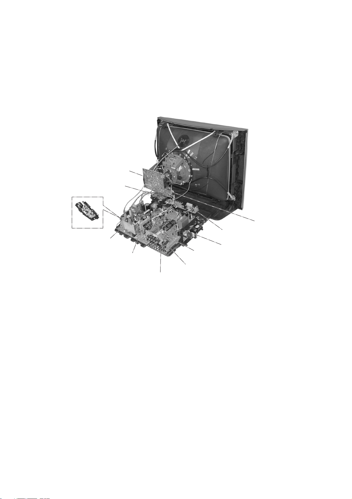
5-2. CIRCUIT BOARDS LOCATION
C6 Board
KV-AR29M90
RM-993
D3 Board
H2 Board
A Board
V1 Board
(Not used for
this model)
VM1 Board
H1 Board
F Board
B1 Board
B10 Board
J Board
– 29 –

KV-AR29M90
RM-993
5-3. SCHEMATIC DIAGRAM
Note:
• All capacitors are in µF unless otherwise noted.
• All electrolytic capacitors are rated at 50V unless otherwise
noted.
• All resistors are in ohms.
kΩ = 1000Ω, MΩ = 1000kΩ
• Indication of resistance which does not have rating electrical
power is as follows.
Pitch: 5 mm
Rating electrical power 1/4W (CHIP: 1/10W)
• : nonflammable resistor.
• ¢ : internal component.
• : panel designation or adjustment for rrepair.
• All variable and adjustable resistors have characteristic curve
B unless otherwise noted.
• Redings are taken with a color-bar signal input.
no mark : Common
(): PAL
[ ] : NTSC 3.58
• Readings are taken with a 10 Ω digital multimeter.
• Voltage are dc with respect to ground unless otherwise
noted.
• Voltage variations may be noted due to normal production tolerances.
• All voltage are in V.
• ✽ : Cannot be measured.
• Circled numbers are waveform references.
• : B +bus.
• : B –bus.
• ÷ : signal path.
Reference information
RESISTOR : RN METAL FILM
COIL : LF-8L MICRO INDUCTOR
CAPACITOR : TA TANTALUM
Note: The component identified by shading and
: RC SOLID
: FPRD NONFLAMMABLE CARBON
: FUSE NONFLAMMABLE FUSIBLE
: RS NONFLAMMABLE METAL OXIDE
: RB NONFLAMMABLE CEMENT
: RW NONFLAMMABLE WIREWOUND
: ✽ ADJUSTMENT RESISTOR
: PS STYROL
: PP POLYPROPYLENE
: PT MYLAR
: MPS METALIZED POLYESTER
: MPP METALIZED POLYPROPYLENE
: ALB BIPOLAR
: ALT HIGH TEMPERATURE
: ALR HIGH RIPPLE
mark ! are critical for safety. Replace only
with part number specified.
– 30 –
 Loading...