

Sony KV43TR27, Trinitron KV-13TR27 Service Manual

KV43TR27
RM-781
SERVICE MANUAL
US Model
Chassis No.
SCC-D37L-A
Canadian Model
Chassis No.
SCC-D36H-A
P-3B
CHASSIS
Television system
Channel coverage
Picture tube
Power requirements
Power consumption
Accessories supplied
Optional accessories
Speaker size :
American TV standards
VHF : 2-13
UHF : 14-69
MODELS OF THE SAME SERIES
1 KV-13TR24X
I
I
KV-13TR14,‘13TR24
SPECIFICATIONS
Speaker Impedance
Speaker Wattage
Dimensions
Weight
812
Approx. 2W
Approx. 356X 331 X 407 mm (w/h/d)
Approx. 10.5kg
Cable TV : 1-125
Mirror black Trinitron tube
13-inch picture measured diagonally
14-inch picture tube measured diagonally
VIDEO IN (phono jack) : lVp-p,
75ohms unbalanced, sync negative
AUDIO IN(phono jack) : 408mVrms
(100%
modulation)
impedance : 47k ohms
120V AC, 60Hz
97W (Max.) 3W (STAND BY)
Remote Commander RM-781
.
with 2 size AA (R6) batteries
VHF/UHF telescopic dipole antenna (1)
Antenna connector (1)
U/V mixer EAC-66
Connecting cord
VMG606M/607M,
etc.
77mm X 1
Designs and specifications are subject to change without
notice.
TRINITRONB
COLOR TV
SONY@
TABLE OF CONTENTS
Section Title
m
1. GENERAL
1-1.
Location
of
Controls.. ....................................... .
l-2.
Presetting
TTJ
Channels.. ....................
Z..
...........
5
1-3.
Watching
TT,~
Programs..
..................................
.
l-4.
Adjusting
the Picture
.......................................
6
1-5.
Enjoying the Convenient Features ....................7
l-6.
Timer/Block..
................................................... .
2. DISASSEMBLY
2-l.
Service Position
..............................................
10
2-2.
Picture Tube Removal ....................................
11
3. SET-UP ADJUSTMENTS
3-l.
Beam Landing
.................................................
12
3-2.
Convergence.. ..................................................
13
3-3.
Focus ..............................................................
14
3-4.
Sub
BRT
.........................................................
14
3-5.
White Balance .................................................
14
WARNING !!
ATTENTION!!
AN ISOLATION TRANSFORMER SHOULD BE USED
DURING ANY SERVICE TO AVOID POSSIBLE SHOCK
HAZARD, BECAUSE OF LIVE CHASSIS.
THE CHASSIS OF THIS RECEIVER IS DIRECTLY CONNECTED TO THE AC POWER LINE.
AFIN D’EVITER TOUT RISQUE D’ELECTROCUTION
PROVENANT D’UN CHkBIS SOUS TENSION, UN
TRANSFORMATEUR D’ISOLEMENT DOIT ETRE
UTILISC LORS DE TOUT
DiPANNAGE.
LE CHk!SlS DE CE RiCEPtEUR EST DIRECTEMENT
RACCORO~ i& L’ALIMENTATION SECTEUR.
SAFETY-RELATED COMPONENT WARNING !!
COMPONENTS IDENTIFIED BY SHADING AND MARK
A
ON THE SCHEMATIC DIAGRAMS, EXPLODED
VIEWS AND IN THE PARTS LIST ARE CRITICAL TO
SAFE OPERATION. REPLACE THESE COMPONENTS
WITH SONY PARTS WHOSE PART NUMBERS APPEAR
AS SHOWN IN THIS MANUAL OR IN SUPPLEMENTS
PUBLISHED BY SONY. CIRCUIT ADJUSTMENTS
THAT ARE CRITICAL TO SAFE OPERATION
AkE
IDENTIFIED IN THIS MANUAL. FOLLOW THESE PRO-
CEDURES WHENEVER CRITICAL COMPONENTS ARE
REPLACED OR IMPROPER OPERATION IS SUSPECTED.
Section
4. SAFETY RELATED ADJUSTMENT....................... 15
5. ELECTRICAL ADJUSTMENTS
5-1.
A Board
Adjustment
. . . . . . . . . . . . . . . . . . . . . . . . . . . . . . . . . . . . . . .
17
6. DIAGRAMS
6-1.
Circuit Board Location.. .................................
19
6-2.
Printed Wiring Board
.....................................
20
6-3.
Schematic Diagram ..........................................
23
6-4.
Semiconductors.. ..............................................
27
7.
EXPLODED VIEW
. . . . . . . . . . . . . . . . . . . . . . . . . . . . . . . . . . . . . . . . . . . . . . . . . . .
28
8.
ELECTRICAL
PARTS LIST
. . . . . ..a............................
29
ATTENTION AUX COMPOSANTS RELATIFS A LA
ShURITi!!
LES COMPOSANTS IDENTIFIiS PAR UNE TRAME ET
PAR UNE MARQUE
ASUR
LES
SCHiMAS
DE PRiNCIPE,
LES VUES EXPLOSiES ET LES LISTES DE PIECES
SONT D*UirE IMPORTANCE CRITIQUE POUR LA
SiCURlTi
DU FONCTIONNEMENT. NE LES REM-
PLACER QUE PAR DES COMPOSANTS SONY DONT LE
NUMiRO DE PIiCE EST INDlOUi DANS LE
PRhENT
MANUEL OU DANS DES SUPPLiMENTB PUBLliS PAR
SONY. LES RiGLAGES DE ‘*CIRCUIT DONT L’IMPOR-
TANCE EST CRITIQUE POUR LA SkCURITi DU
FONCTIONNEMENT SONT IDENTIFIES DANS LE
PRiSENT MANUEL. SUIVRE CES PROCiDURES LORS
DE CHAOUE REMPLACEMENT DE COMPOSANTS
CRITIQUES. OU LORSQU’UN
MAUVAIS
FONCTIONNE-
MENT EST SUSPECTi.
-2-
SAFETY CHECK-OUT
(
KV-13W871
(US Model only)
After correcting the original service problem,
perform the following safety checks before releasing
the set to the customer:
1.
Check the area of your repair for unsoldered or
poorly-soldered connections. Check the entire
board surface for solder splashes and bridges.
2.
Check the inierboard wiring to ensure that no
wires are “pinched” or contact high-wattage
resistors.
3.
Check that all control knobs, shields, covers,
ground straps, and mounting hardware have
been replaced. Be absolutely certain that you
have replaced all the insulators.
4. Look for unauthorized replacement parts, particularly transistors, that were installed during a
previous repair. Point them out to the customer
and recommend their replacement.
5.
Look for parts which, though functioning, show
obvious signs of deterioration. Point them out
to the customer and recommend their replacement ,
6.
Check the line cord for cracks and abrasion.
Recommend the replacement of any such line
cord to the customer.
7.
Check the condition of the monopole antenna
(if any).
Make sure the end is not broken off, and has
the plastic cap on it. Point out the danger of
impalement on a broken antenna to the
customer,
and’ recommend the antenna’s
replacement.
8.
Check the B+ and HV to see they are at the
values specified. Make sure your instruments
are accurate; be suspicious of your HV meter
if sets always have low HV.
9.
Check the antenna terminals,
meta!
trim,
“metallized” knobs, screws, and all other
exposed metal parts for AC leakage.
Check
leakage as described below.
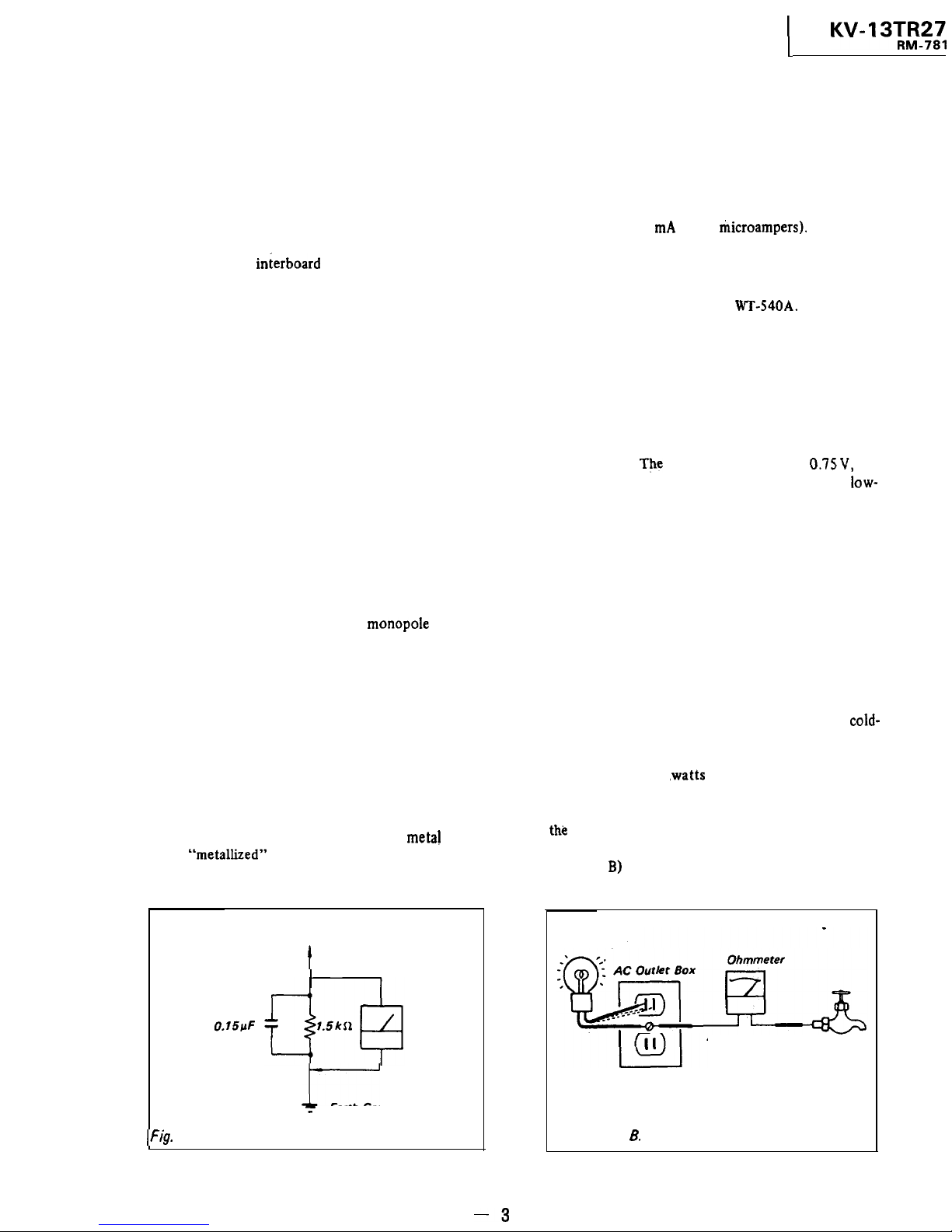
LEAKAGE TEST
The AC leakage from any exposed metal part to
earth ground and from all exposed metal parts to any
exposed metal part having a return to chassis, must
not exceed 0.5 mA (500 microampers).
Leakage
current can be measured by any one of three
methods.
1.
A commercial leakage tester, such as the
Simpson 229 or RCA
WT-540A.
Follow the
manufacturers’ instructions to use these instruments.
2.
A battery-operated AC milliammeter. The Data
Precision 245 digital multimeter is suitable for
this job.
3. Measuring the voltage drop across a resistor by
means of a VOM or battery-operated AC voltmeter.
The
“limit” indication is 0.75V, so
analog meters must have an accurate
low-
voltage scale. The Simpson 250 and Sanwa
SH-63Trd are examples of a passive VOM that
is suitable. Nearly all battery operated digital
multimeters that have a 2V AC range are
suitable. (See Fig. A)
HOW TO FIND A GOOD EARTH GROUND
A cold-water pipe is guaranteed earth ground; the
cover-plate retaining screw on most AC outlet boxes is
also at earth ground. If the retaining screw is to be
used as your earth-ground, verify that it is at ground
by measuring the resistance between it and a
cold-
water pipe with an ohmmeter. The reading should be
zero ohms. If a cold-water pipe is not accessible,
connect a 60-100
.watts
trouble light (not a neon
lamp) between the hot side of the receptacle and the
retaining screw. Try both slots, if necessary, to locate
the
hot side of the line, the lamp should light at
normal brilliance if the screw is at ground potential.
(See Fig.
B)
To Exposed Me tat
Parts on Set
I
0.15pF
AC
voltmeter
10.75 VI
I
-
Earth Ground
liig. A.
Using an AC voltmeter to check AC leakage.
Fig. 6.Checking for earth ground.
Trouble Light
Cold-water Pipe
-3
SECTION I
GENERAL
l-l. LOCATION OF CONTROLS
Ffefer
to the
pai
mdlcated I” 0 for detals
Monitor-
I
P
r----------u
I
I
I
I
b
I
I
1---------I
TV,VIDEO button ’
me....
control detector
VOLUME
+/-
buttons
TfMER lamp
CHANNEL
+/-
buttons
bOWER
switch
On-screen displays
a *
Channel numbers
. “MUTfNG”or “SLEEP” mdlcatlon
. ‘VIDEO
lndlcatu3n
b) -
‘AUTO PROGRAM’, ‘TIMER or TIMER
BLOCK mdlcaton
c) *
Bar dwplay for volume OP
picture
adJustmeN
.
Currpnt +,me
for
Twner/Block
AUDIO IN jack
VIDEO IN jack
VHF/UHF antenna terminal
RemotecornmandsrRY-781
MUTING button
TIMER/BLOCK setting buttons
-
(TIMER/BLOCK, CLEAR, AM/PM,
OFF/REPEAT)
Channel presetting buttons
-
(AUTO PGM, ADD, ERASE)
Channel number buttons
-
DISPLAY button
PICTURE
+I-
buttons
*
VOL (volume)
+I-
buttons
-
-SLEEP
button
-*
POWER switch
Picture adjusting buttons
(SELECT, RESET, LEVEL
1
CABLE button
*
TV/VIDEO button
6)
ENTER button
JUMP button
*
CH (channel) +/-buttons
-The functions of these buttons
are also
available
on ihe TV.
. In normal operaton.
batteries will
last up to half a year.lf
the Commander does not operate properly, the
batteries
might
be exhausted Replace them wth new ones.
l To
avoid
damage from
posstble
battery leakage, remove
the battenes when the Commander wll not be used for a
long me.
l If a Remote Commander that
IS
not recommended IS used
to operate
this N.
or of the suppked Remote Commander
1s
used to operate another N. the TV may not operate
properly
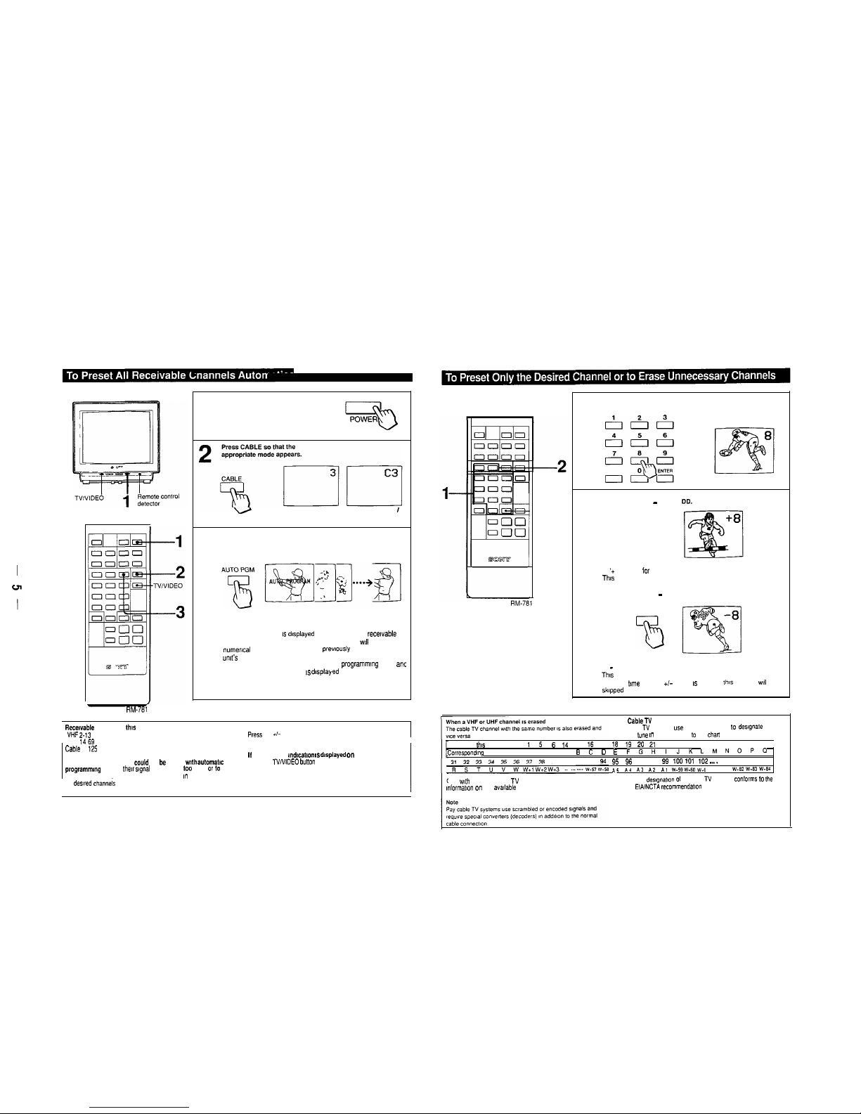
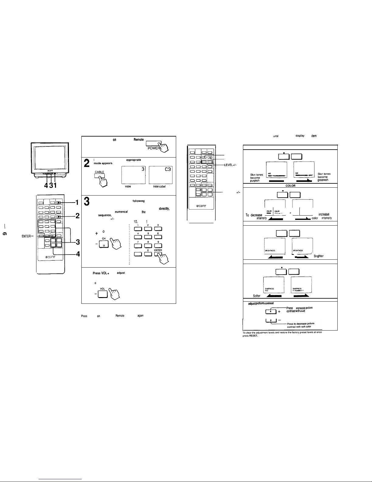
l-2. PRESETTING TV CHANNELS
RM-781
1
Press POWER on the TV or the Remote
Commander to turn the N on.
To preset VHF or UHF
To preset cable TV
channels channels
3
Press AUTO PGM.
“AUTO PROGRAM IS dlsplayed on the screen and recavable
channels (other than the channels already preset) wll be preset I”
numerical sequence The channels
prewously
preset reman I” the
umt’s
memory
When no more channels can be found the
programrmng
stops ant
the lowest numbered channel IS dIsplayed
Recewable channels of thls TV are:
I
VHF 2.13
TO check Preset channels
PESS CH +,-
1 UHF ,469 I
Cable
1
125
I,
the “VIDEO”
md,catlon IS dasplayed
on the screen
To add the channels that
could
not be preset wth
automatic
p,og,amm,ng because the,, s,gna, strength was loo weak or lo
erase unnecessary channels, follow the steps I”To preset only
Press the TVNIDEO bunon on the TV or the Remote
Commander so that a channel “umber appears
the
dewed
channeis on the next Page
-ENTER
1
Press the channel number button(s) and then ENTER to select
the channel to be added or erased.
2
To add channels - Press A
ADD
a
A ‘+ appears ior a moment
This
channel has now bee” added to the channel scan memory
To erase channels - Press ERASE.
ERASE
T3
A - appears for a moment
Thus
channel has now bee” erased from the channel scan memory
The next
t,me
the CH +/- button IS pressed
this
channel
will
be
skipped
Repeat steps 1 and 2 for other channels to be added or erased
CableT” channel chart’
Cable TV systems use letters or numbers 10 designate channels
To tune I” a channel refer lo the
cha”
below
Number on this TV
1
5
6 14 15 15 17 18 19 20 21 22 23 24 25 26 27 28 29 30
Correspo”d!“g
CAT” channel A 8 A-7 A-6 A
B
c 0
E
FGHIJK
LMNOPrI
39
. . . . . . . . . . . . . . . .
$3 95 96 97 98 99 100 to, 102
..__
123 124 125
115 1\4 4\3 .a2 1\? w-59w.60~.6
W.82 W.83
wed
Check
w,th your local cable TV company for more complete
.
The des,g”at,on of the cable TV channels conformS 10 the
,nformabon on the ava,,able channels
EWNCTA recommendat~o”
I
aa
I
l-3. WATCHING TV PROGRAMS
ENTER-
RM-781
1
Press POWER on the N or the
Remote
Commander to turn the N on.
Press SELECT repeatedly
unto1
the on-screen
display
of the
Item
lo be adjusted
appears. then press LEVEL +/-
Press CABLE so that the
appropriate
RESET
SELECT
LEVEL+/-
purplish
To
wew
VHF or UHF
To wew cabel TV
channels
channels
3
Select a channel in one of the
followmg
two ways:
To scan the preset
:
To select a channel dwectly,
channels in numerICal :
press the channel number
SeCf”e”Ce,
I button(s) and then ENTER
press CH
+I-
I For example, to select channel
1
10.
press 1 0 and ENTER
f
o
0
-PICTURE +/-
- LEVEL +
no
r--I
RM-781
~~
decrease 1
=
1
k-*
- 1 TO
mcrease
color mterwty
-
L
color
lntenslty
BRIGHT (brightness)
- LEVEL +
IO
1
’
Darker
1
- .y
Srlghter
SHARP (sharpness)
- LEVEL +
4
press VOL + or-to adlust the volume.
f
0
Note
To turn off the N
To
adlust plCt”FZ COtItraSt
IZF-
press
to
InCreaSe pcture
cm,,ras, w,,h wwd
color
Press POWER on the TV or the Remote Commander
awn
PICTURE
14. ADJUSTING THE PICTURE
HUE
- LEVEL +
-\
Sharper
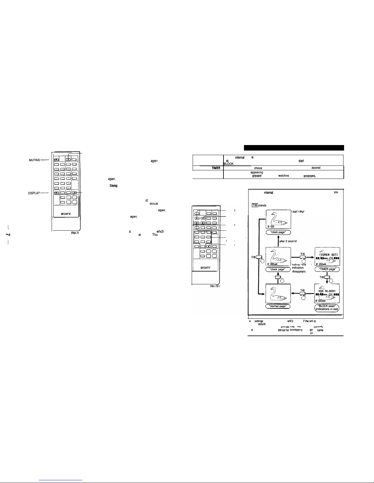
l-5. ENJOYING THE CONVENIENT FEATURES l-6. TIMER/BLOCK
MUTING-
DISPLAY-
RM-7t
-SLEEP
Muting the sound
Press MUTING.
The “MUTING” indication will appear on the screen.
To restore the sound. press MUTING
agal”
or VOL +
Keeping the channel displayed
Press DISPLAY.
To make the channel display disappear, press DISPLAY
agal”.
Using
the SLEEP timer
-JUMP
Press SLEEP
The TV will be turned off automatically after about one hour.
The green “SLEEP ON” indication will appear on the screen
for a few seconds when SLEEP 1s pressed and the red
“SLEEP” indication will appear one mmute before the TV is
turned off.
To cancel the SLEEP timer, press SLEEP
agam.
or turn off
the TV. The “SLEEP OFF” indication will appear when
SLEEP is pressed
agam.
Switching quickly between two channels
Press JUMP
Each time JUMP IS pressed. the channel which appeared on
the screen directly before IS recalled.
Thts
button enables
you to keep track of two programs alternately.
Internal clock
Once the Internal clock IS set. the current time will appear on the screen.
It IS necessary to set the clock correctly to activate the program stalt TIMER and channel
Program start
TlMER
Makes a program of your
choice
appear on the screen automatically at the dewed time.
Channel BLOCK
Blocks a channel from appearmg on the screen for 12 hours.
Use channel BLOCK to mevent children from watchma undesirable
proarams.
The buttons used for the above functions
are located on the Remote Commander.
CLEAR
I
I
TIMER/BLOCKTIMER/BLOCK
AM/PM
OFF/REPEAT
Channel numberChannel number
buttons
I
ENTER
To set the mternal clock, program start TIMER and channel BLOCK,
YOU
must summon the corresponding “pages”. “clock page.” “TIMER page”
and “BLOCK page.”
To change the “pages”. press TIMEWBLOCK.
IT/Bstands for the TIMEWBLOCK button.
k--l
“AM”/“PM”
indication disappears
before “AM/PM”
T/B
a
All settmgs will be erased from the unit3 memory it the umt 15 unplugged. or if a power
failure
omws.
. The TIMER and BLOCK will overate ontv if :he clock is set correctI”.
. ,I the TIMER and BLOCK are
;et tar o”&pp,“g
times .,n the
sam;
channel. the
blocked channel wilt appear on the screen at the time set on the TIMER.
I
co
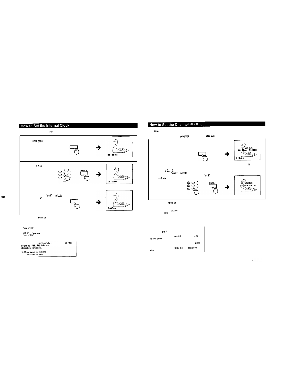
I
Example: To set the clock to
9:OS
PM
1
Press TIMER/BLOCK once to change from “normal page”
to
“clock
page.-
TIMEWBLOCK
“clock page”
2
Press 0.9,O. 5 AM/PM (0 necessary).
I I 1
3
If you have performed the operation correctly, press
ENTER.
The numbers will “wmk” to
Indicate
that the clock has been
set. (The 0 m front will disappear.)
ENTER
If you have made a mistake, press CLEAR and return to step 2.
The “AM/PM” indication will disappear after 2 seconds.
To summon “TIMER page,” press TIMER/BLOCK before
the “AM”/“PM” indication disappears.
To retwn to
“normal
page,” press TIMER/BLOCK after
the “AM”/“PM” indication has disappeared.
To reset the clock, s”mm~” “cloCk page” and
Press
CLEAR
before the “AMY’PM” indication disappears. Then follow the
Make
sure
that the clock has been set correctly before Setting the channel BLOCK.
Example: To set the BLOCK for a program which begins at
930 AM
on channel 9
1
Press TIMER/BLOCK three times to change from “normal
page” to “BLOCK page.”
TIMEWBLOCK
“BLOCK page”
(indications m red)
2
Press
0.9.3.0.
ENTER (0 necessary).
Numbers will “wmk” to
Indicate
that the time has been Set.
Press 8, ENTER (0 not necessary). Numbers will “wmk” to
Indicate
that the channel has been Set.
The BLOCK has now been set.
If you have made a mstake, press CLEAR and return to
step 2.
At the preset time, the
picture
of the selected channel will
be blocked from wew and the sound will be muted.
A red “BLOCKED’ indication will appear on the screen while
the channel is blocked.
Normal reception will be resumed after 12 hours.
To return to normal reception white the channel is blocked,
recall “BLOCK page” and press CLEAR.
The BLOCK setting blocks a speafled channel for the same
12.how pewad everyday.
TO clear BLOCK setting. summon “BLOCK page” and Press
CLEAR.
To reset, clear the setting and follow fhe steps
above
from
steo 2.

I
W
Make sure that the clock has been set correctly before setting the program start TIMER.
Example: To set the TIMER for a program
which
begins at IO:30 PM on channel 12
1
Press TIMERBLOCK once to change from
“normal page” to “clock page.”
TIMEWBLOCK
“clock page”
2
Press TIMER/BLOCK before the “AWf’PM”
indlcabon
disappears and summon “TIMER
page
,*
TIMER/BLOCK
“TIMER page”
3
Press 1.0.3.0, AM/PM, ENTER
Numbers
will
“v,“W lo
lndlcate
that the
bme
has
been
SB,
&I&;,
. I 6
AM/PM ENTER
4
Press 1,2, ENTER (0 not necessary)
Numbers
will
“wmk” to
mdlcate
that the
channel has been set
The TIMER lamp
wtll ltght
up to
lndlcate
that the TIMER has
been set
If you have
made
a
nIlstake, p’ess
CLEAR
and ref”m 10 step
3
me TIMER operates Only once. but the bme and the channel I”,,,
remam m fhe “W’s
memory
A, the preset
tme,
the selected channel
WI,,
appear on the screen
and the TIMER lamp wtll go out The TIMER
w,,,
operate whether
you are wa,ch,ng a TV Program or a VCR playback. or
eve”
If you
have turned OR the TV
If you want to preset the same channel at the same time for a
MUE
de, press OFF~EPEAT
me
TIMER lamp
w,,
,lght “p
lo indwte ,hai
the TIMER has been r.?acWa,ed
If no
button
is pressed within 2 hours after the preset time. an
‘OFF
,“d,ca,,on “,,I, appear
on
the screen
for 1
m,n”,e If
a
bunon
1s sttll
no,
,o”cCed during
the 1
m,n”,e. the
TV wl,
turn
o”
a”tOmatlCally
a* a
safely
precautvx
If you want
to
deact,vate
the TIMER, press OFF/REPEAT
agan so that ,he TIMER ‘amp goes out I, IS no, necessary to
summa” -TIMER page” to “se the OFF/REPEAT
bun””
F”“hermore. ,h,s
button 15
effective even 1, the
TV has bee”
,“m?.d ofi
To clear the TlUER setting. summon “TIMER page” and press
CLEAR
To reset. clear the seblng and lollaw the s,ePs from step 3
 Loading...