

Sony KV-36FS12, KV-32FV26, KV-32FV16, KV-36FS16, KV-3 6FV26 User Manual
...
4-075-587-23
TM
© 2000 by Sony Corporation
Operating Instructions
KV-32FV16 KV-36FS12 KV-36FV16
KV-32FV26 KV-36FS16 KV-36FV26

WARNING
T o reduce the risk of fire or shock hazard, do not expose the TV to
rain or moisture.
CAUTION
RISK OF ELECTRIC SHOCK
DO NOT OPEN
ATTENTION
RISQUE DE CHOC ELECTRIQUE,
NE PAS OUVRIR
PRECAUCION
RIESGO DE CHOQUE ELECTRICO
NO ABRIR
CAUTION: TO REDUCE THE RISK OF ELECTRIC SHOCK,
DO NOT REMOVE COVER (OR BACK).
NO USER-SERVICEABLE PARTS INSIDE.
REFER SERVICING TO QUALIFIED SERVICE PERSONNEL.
This symbol is intended to alert the user to the
presence of uninsulated “dangerous voltage”
within the product’s enclosure that may be of
sufficient magnitude to constitute a risk of
electric shock to persons.
This symbol is intended to alert the user to the
presence of important operating and maintenance
(servicing) instructions in the literature
accompanying the appliance.
CAUTION
TO PREVENT ELECTRIC SHOCK, MATCH WIDE BL A D E OF
PLUG TO WIDE SLOT, FULLY INSERT.
CAUTION
When using TV games, computers, and similar products with your
TV, keep the brightness and contrast funct ions at low settings. If a
fixed (non-moving) pattern is left on the screen for long periods of
time at a high brightness or contrast setting, the image can be
permanently imprinted onto the screen. Continuously watching
the same program can cause the imprint of station logos onto the
TV screen. These types of imprints are not covered by your
warranty because they are the result of misuse.
Note on Caption Vision
This television receiver provides display of television closed
captioning in accordance with §15.119 of the FCC rules.
Note on Cleaning the TV
Clean the TV with a soft dry cloth. Never use strong solvents such
as thinner or benzine, which might damage the finish of the
cabinet.
Note to CATV System Installer
This reminder is provided to call the CATV system installer’s
attention to Article 820-40 of the NEC that provides guidelines for
proper grounding and, in particular , specifies that the cable ground
shall be connected to the grounding system of the building, as close
to the point of cable entry as practical.
Use of this television receiver for other than private viewing of
programs broadcast on UHF or VHF or transmitted by cable
companies for the use of the general public may require
authorization from the broadcaster/cable company and/or
program owner.
NOTIFICATION
This equipment has been tested and found to comply with the
limits for a Class B digital device pursuant to Part 15 of the FCC
Rules. These limits are designed to provide reasonable protection
against harmful interference in a residential installation. This
equipment generates, uses, and can radiate radio frequency energy
and, if not installed and used in accordance with the instructions,
may cause harmful interference with radio communications.
However, there is no guarantee that interference will not occur in a
particular installation. If this equipment does cause harmful
interference to radio or television reception, which can be
determined by turning the equipment off and on, the user is
encouraged to try to correct the interference by one or more of the
following measures:
❑ Reorient or relocate the receiving antennas.
❑ Increase the separation between the equipment and receiver.
❑ Connect the equipment into an outlet on a circuit different
from that to which the receiver is connected.
❑ Consult the dealer or an experienced radio/TV technician for
help.
You are cautioned that any changes or modifications not
expressly approved in this manual could void your authority
to operate this equipment.
Safety
❑ Operate the TV only on 120 V AC.
❑ The plug is designed, for safety purposes, to fit into the wall
outlet only one way. If you are unable to insert the plug fully
into the outlet, contact your dealer.
❑ If any liquid or solid object should fall inside the cabinet,
unplug the TV im mediately and hav e i t checked by quali fied
service personnel before operating it further.
Installing
❑ T o prevent internal heat buildup, do not block the ventilation
openings.
❑ Do not install the TV in a hot or humid place, or in a place
subject to excessive dust or mechanical vibration.
❑ The AC power cord is attached to the rear of the TV with
hooks. Do not attempt to remove the cord from these hooks.
Doing so could cause damage t o the TV
As an ENERGY STAR Partner,
Sony has determined that this
product or product models meets
NERGY STAR guidelines
the E
for energy efficiency.
ENERGY STAR is a U.S. registered mark.
®
(z)
SRS Sound Retrieval System
The (z) SRS (SOUND RETRIEVAL SYSTEM) is manufactured by
Sony Corporation under license from SRS Labs, Inc. It is covered by
U.S. Patent No. 4,748,669. Other U.S. and foreign patents pending.
The word “SRS” and the SRS symbol (z) are register ed trademarks
of SRS Labs, Inc.
Licensed by BBE Sound, Inc. under USP 4638258.4482866. BBE and
BBE symbol are tra demarks of BBE Sound, Inc .
FD Trinitron and the Wega logo are trademarks of Sony
Corporation.
®
®
®
Owner’s Record
The model and serial numbers are provided on the front of this
instruction manual and at the rear of the TV. Refer to them
whenever you call upon your Sony dealer regarding this product.
About this Manual
This manual is for models KV-32FV16, KV -32FV26, KV-36FS12, KV36FS16, KV-36FV16, and KV-36FV26. The menu and illustrations
shown are for model KV-36FV26 to show the maximum features
available. Differences in operation will be indicated in the text, for
example, “For KV-36FV26 only.”
Important Safeguards
For your protection, please read these instructions completely, and
keep thi s manual for future reference.
Carefully observe and comply with all warnings, cautions and
instructions placed on the set or described in the operating
instructions or service manual.
WARNING
T o guard against injury, the following basic safety precautions
should be observed in the installation, use and servicing of the set.
Use
Pow er S our ces
This set should be operated only from the type
of power source indicated on the serial/model
plate. If you are not sure of the type of electrical
power supplied to your home, consult your
dealer or local power company . For those sets
designed to operate from battery power, refer
to the operating instructions.
Grounding or Polarization
This set is equipped with a polarized AC power cord plug (a plug
having one blade wider than the other), or with a three-wire
grounding type plug (a plug having a third pin for
grounding).Follow the instructions below:
For the set with a polarized AC power cord plug
This plug will fit into the power outlet only one
way . This is a safety feature. If you are unable to
insert the plug fully into the outlet, try reversing
the plug. If the plug still fails to fit, contact your electrician to have
a suitable outlet installed. Do not defeat the safety purpose of the
polarized plug by forcing it in.
Alternate Warning
For the set with a three-wire grounding type AC plug
This plug will only fit into a grounding-type
power outlet. This is a safety feature. If you are
unable to insert the plug into the outlet, contact
your electrician to have a suitable outlet installed.
Do not defeat the safety purpose of the grounding plug.
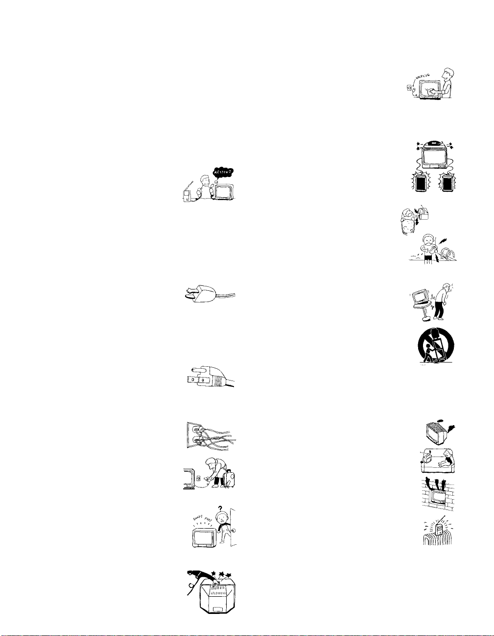
Overloading
Do not overload wall outlets, extension cords or
convenience receptacles beyond their capacity,
since this can result in fire or electric shock.
Always turn the set off when it is not being
used. When the set is left unattended and
unused for long periods of time, unplug it
from the wall outlet as a precaution against
the possibility of an internal malfunction that
could create a fire hazard.
If a snapping or popping sound from a TV set is
continuous or frequent while the TV is operating,
unplug the TV and consult your dealer or service
technician. It is normal for some TV sets to make
occasional snapping or popping sounds,
particularly when being turned on or off.
Object and Liquid Entry
Never push objects of any kind into the set
through the cabinet slots as they may touch
dangerous voltage points or short out parts that
could result in a fire or electric shock. Never spill
liquid of any kind on the set.
Cleaning
Unplug the set from the wall outlet before
cleaning or polishing it. Do not use liquid
cleaners or aerosol cleaners. Use a cloth lightly
dampened with water for cleaning the exterior
of the set.
Installation
Attachments
Do not use attachments not recommended by the
manufacturer, as they may cause hazards.
Water and Moisture
Do not use power-line operated sets near
water — for example, near a bathtub,
washbowl, kitchen sink, or laundry tub, in a
wet basement, or near a swimming pool, etc.
Accessories
Do not place the set on an unstable cart, stand,
table or shelf. The set may fall, causing serious
injury to a child or an adult and serious damage
to the set. Use only a cart or stand recommended
by the manufacturer for the specific model of TV.
An appliance and cart combination should be
moved with care. Quick stops, excessive force,
and uneven surfaces may cause the appliance and
cart combination to overturn.
Ventilation
The slots and openings in the cabinet and in the back or bottom are
provided for necessary ventilation. To ensure reliable operation of
the set, and to protect it from overheating, these slots and openings
must never b e blocked or covered.
❑ Never cover the slots and openings with a
cloth or other materials.
❑ Never block the slots and openings by
placing the set on a bed, sofa, rug or other
similar surface.
❑ Never place the set in a confined space, such
as a bookcase or built-in cabinet, unless
proper ventilation is provided.
❑ Do not place the set near or over a radiator
or heat register , or where it is exposed to
direct sunlight.
Power-Cord Protection
Do not allow anything to rest on or roll over the
power cord, and do not place the set where the
power cord is subject to wear or abuse.
Antennas
Outdoor Antenna Grounding
If an outdoor antenna is installed, follow the pr ecautions below. An
outdoor antenna system should not be located in the vicinity of
overhead power lines or other electric light or power circuits, or
where it can come in contact with such power lines or circuits.
WHEN INSTALLING AN OUTDOOR ANTENNA SY ST EM,
EXTREME CARE SHOULD BE TAKEN TO KEEP FROM
CONTACTING SUCH POWER LINES OR CIRCUITS AS
CONTACT WITH THEM IS ALMOST INVARIABLY FATAL.
Be sure the antenna system is grounded so as to provide some
protection against voltage surges and built-up static charges.
Section 810 of the National Electrical Code (NEC) in USA and
Section 54 of the Canadian Electrical Code in Canada provides
information with respect to proper grounding of the mast and
supporting structure, grounding of the lead-in wire to an antenna
discharge unit, size of grounding conductors, location of antenna
discharge unit, connection to grounding electrodes, and
requirements for the grounding electrode.
Antenna Grounding According to the NEC
Refer to section 54-300 of Canadian Electrical Code for Antenna
Grounding.
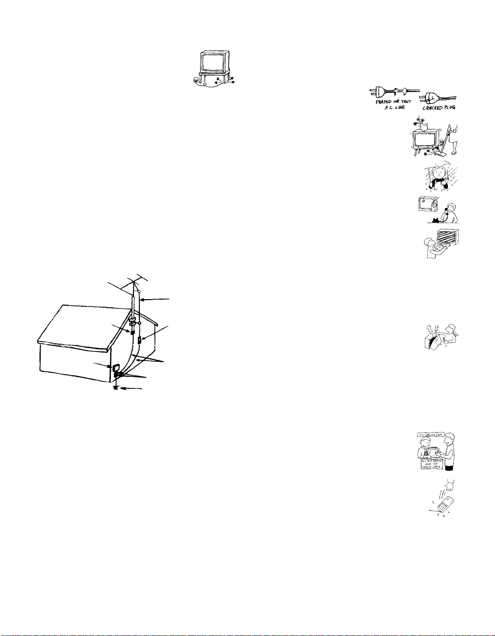
Service
Damage Requiring Servic e
Unplug the set from the wall outlet and refer servicing to qualified
service personnel under the following conditions:
❑ When the power cord or plug
is damaged or frayed.
❑ If liquid has been spilled into
the set.
❑ If the set has been exposed to
rain or water.
❑ If the set has been subject to
excessive shock by being
dropped, or the cabinet has
been damaged.
❑ If the set does not operate
normally when following the
operating instructions. Adjust
only those controls that are
specified in the operating
instructions. Improper
adjustment of other controls
may result in damage and
will often require extensive
work by a qualified technician
to restore the set to normal operation.
Antenna lead-in wire
Ground clamp
Electrical wire
equipment
NEC: National Electrical Code
Antenna discharge unit
(NEC Section 810-20)
Ground clamps
Antenna lead-in wire
Power service grounding electrode
system (NEC Art 250 Part H)
Lightning
For added protection for this television receiver during a lightning
storm, or when it is left unattended and unused f or lo ng periods of
time, unplug it from the wall outlet and disconnect the antenna.
This will prevent damage to the receiver due to lightning and
power-l ine surges.
❑ When the set exhibits a distinct change in performance, it
indicates a need for service.
Servicing
Do not attempt to service the set yourself since
opening the cabinet may expose you to dangerous
voltage or other hazards. Refer all servicing to
qualified service personnel.
Replacement Parts
When replacement parts are required, be sure the service
technician certifies in writing that he has used replacement parts
specified by the manufacturer that have the same characteristics as
the original parts.
Unauthorized substitutions may result in fire, electric shock or
other hazards.
Safety Check
Upon completion of any service or repairs to the
set, ask the service technician to perform routine
safety checks (as specif ied b y t he manufacturer) to
determine that the set is in safe operating
condition, and to so certify. When the set reaches
the end of its useful life, improper disposal could
result in a picture tube implosion. Ask a qualified
service technician to dispose of the set.

Contents
Introducing the FD Trinitron Wega
Overview................................................................1
Presenting the FD Trinitron Wega......................2
Using the Remote Control...................................3
Installing the TV
Overview................................................................7
TV Controls and Connectors...............................8
Connecting a Cable or Antenna........................10
Connecting a VCR and Cable....................... .... .14
Connecting a VCR and Cable Box................... .15
Connecting Two VCRs for Tape Editing.........17
Connecting a Satellite Receiver........................ .18
Connecting a Satellite Receiver wi th a VCR...19
Connecting an Audio Receiver.........................21
Connecting a DVD Player with Component
Video Connectors........................................22
Connecting a DVD Player with
A/V Connectors..........................................23
Connecting a Camcorder........................... ........24
Using the CONTROL S Feature........................25
Setting Up the TV Automatically.....................26
Using the Features
Overview..............................................................27
Using Favorite Channels....................................28
Using Picture in Picture (PIP) ...........................29
Using Wireless Headphones .............................32
Using the Menus
Overview..............................................................35
Using the Video Menu.................................... ...36
Using the Audio Menu......................................38
Using the Channel Menu...................................40
Using the Parent Menu ......................................42
Using the Timer Menu.......................................45
Using the Setup Menu........................................47
Using the Basic Menu.........................................49
Other Information
Overview..............................................................51
Troubleshooting..................................................57
Specifications.......................................................59
Index.....................................................................61
v


Introducing the FD Trinitron Wega
Overview
This chapter defines the contents of your Wega TV and provides an
overview of how to set up and use basic features.
Topic Page
Presenting the FD Trinitron Wega 2
Contents 3
Using the Remote Control 3
1

Introducing the FD Trinitron Wega
Presenting the FD Trinitron Wega
The FD Trinitron Wega (pronounced VAY-GAH) is characterized by
outstanding contrast, uncompromising accuracy, and corner-tocorner detail.
You’ll recognize the superiority of Wega technology almost
immediately. The first thing you’ll notice is minimal glare from the
flat picture tube. This flat-screen technology improves picture detail
without distortion, unlike conventional curved screens. The FD
Trinitron delivers outstanding image detail not only at the screen
center, but also at the corners — so you can enjoy a bright, clear
picture from any location in a room.
Features Some of the features that you will enjoy with your new TV include:
❑ 16:9 Enhancement: Vertical Compression technology that
maximizes picture resolution on “anamorphic” or “enhanced for
widescreen” sources, including selected DVDs.
❑ Velocity Modulation: Vertical line enhance ment that sharpens
picture definition.
❑ Steady Sound: Equalizes volume levels so there is consistent
output between programs and commercials.
❑ Parental Control: V-Chip technology allows parents to block
unsuitable programming for younger viewers.
❑ Component V ideo Inputs: Offers the best video quality for DVD
player connections.
❑ S-VIDEO Inputs: Provides a high-quality image for connected
equipment.
❑ Dual Tuner Picture in Picture (PIP): Allows you to watch two
programs at once (except model KV-36FS12).
❑ Favorite Channel Preview: Preview up to eight favorite channels
without leaving the current channel (except model KV-36FS12).
❑ Wireless Infrared Headphones: Enjoy listening to programs
without disturbing anyone else (models KV-32FV26, 36FV26
only).
2
Introducing the FD Trinitron Wega
Contents
Your box contains your new Trinitron TV, a remote control and two
AA batteries. No peripheral cables are included with this TV. Please
check the hookup instructions fo r your desired setup before you
begin. You may need to purchase cables and/or splitters to complete
the hookup properly.
Models KV-32FV26 and 36FV26 also contain wireless headphones
and one additional AA battery.
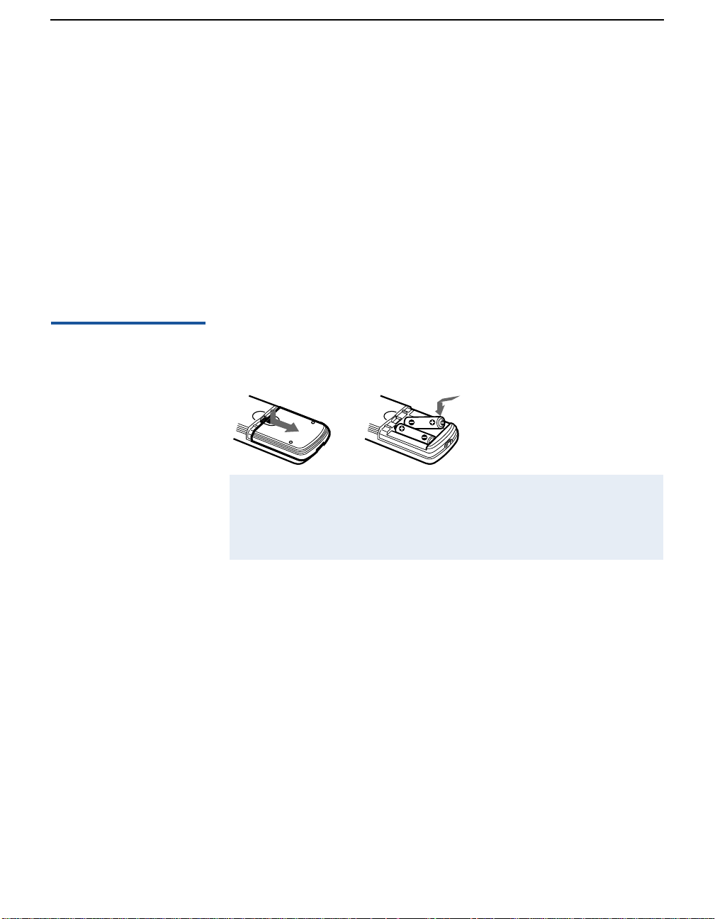
Using the Remote Control
Inserting Batteries Insert two size AA (R6) batteries (supplied) by matching the + and –
on the batteries to the diagram inside the battery compartment.
✍ Remove the batteries to avoid damage from possible battery leakage whenever
you anticipate that the remote control will not be used for an extended period.
Handle the remote control with care. Avoid dropping it, getting it wet, or
placing it in direct sunlight, near a heater, or where the humidity is high.
3
Introducing the FD Trinitron Wega
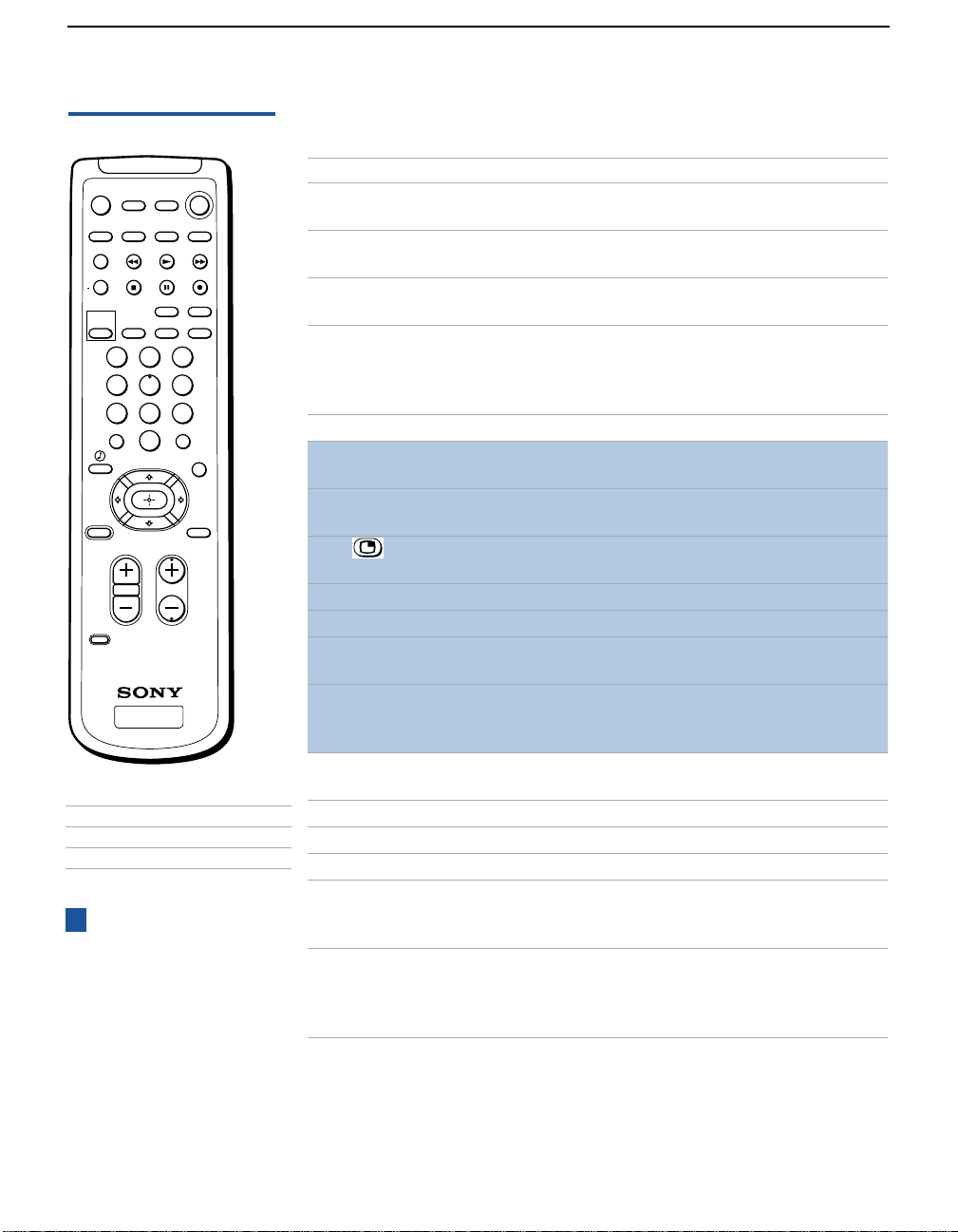
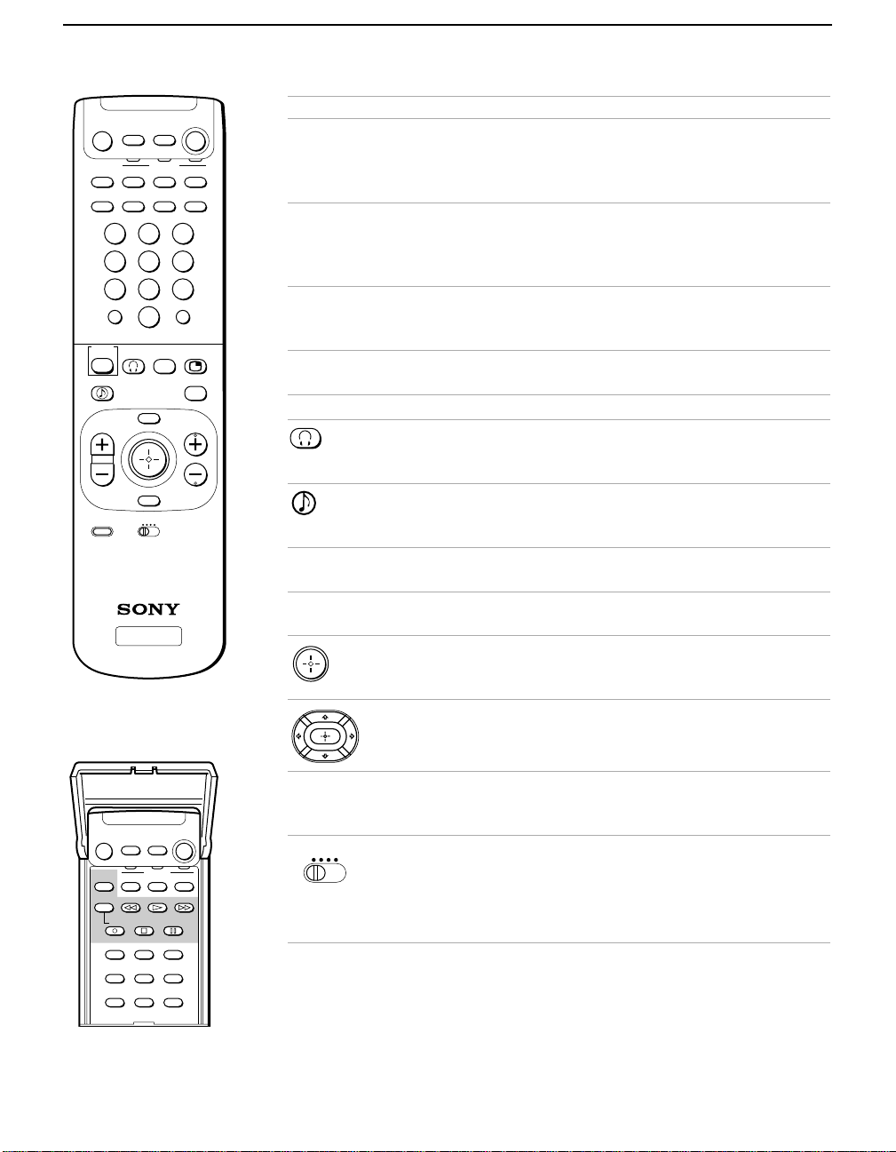
Button Descriptions
MUTING
SYSTEM
TV/VTR
+
PICTURE
MODE
OFF
CH
VTR/DVD
VTR/DVD
FREEZE
POSITION
SLEEP MTS/SAP
SAT/CABLE
SAT/CABLE
SWAP
AUDIO
ANT TV/VIDEO
POWER
TV
TV
PIP
TV/VIDEO
DISPLAY
1 2 3
4 5 6
7 809
JUMP
TV/SAT
RESET MENU
CODE SET
ENTER
GUIDE
CHVOL
RM-Y169
TV
Model Remote
KV-36FS16
KV-32FV16 and 36FV16
KV-36FS12
KV-32FV26 and 36FV26
z
Yellow Picture-in-Picture
buttons (highlighted above right)
are not available on the RM-Y168
remote (model KV-36FS12).
Buttons with asterisks (*) in the list
are located on the inside panel of
the RM-Y170 remote (models
KV-32FV26 and 36FV26).
RM-Y169
RM-Y171
RM-Y168
RM-Y170
Button Description
MUTING Mutes the sound. Press again or press VOL + to res tore
the sound.
POWER buttons
(GREEN)
Turn on and off the TV and other audio/video
equipment.
SYSTEM OFF Powers off all Sony equipment at once. (This feature
may not work wi th older Sony equi pment.)
FUNCTION buttons
(WHITE or BLACK)
Select the equipment (TV, VCR/DVD, SAT/CABLE)
that you want to operate. The indicator lights up
momentarily when pressed to show which device the
remote control is operating.
* TV/VTR Changes the VHF/UHF output of the VCR.
* FREEZE Freezes the window picture. Press again to restore the
picture.
SWAP Switches the position of the main picture with the
window picture.
PIP or Turns on/off PIP. For details, see “Using Picture in
Picture (PIP)” on page 29.
* CH+/- Changes the channel in the window picture.
* POSITION Moves the location of the window picture.
* AUDIO Alternates sound between the main picture and the
window picture.
* PIP TV/VIDEO In the window picture, cycles thr ough the vi deo
equipment connected to your TV’s video inputs: TV ,
VIDEO 1, VIDEO 2, VIDEO 3, VIDEO 4.
* TV/VIDEO Cycles through the video equipment connected to your
TV’s video inputs.
* DVD MENU Displays the DVD menu.
* TITLE Displays the DVD’s Title menu.
ANT Changes the VHF/UHF input to the AUX input.
PICTURE MODE Cycles through the available video picture modes: Vivid,
Standard, Movie, Sports. Also available in the V ideo menu.
For details, see “Selecting Video Options” on page 36.
SLEEP Press repeatedly until the TV displays the time in
minutes (15, 30, 45, 60, or 90) that you want the TV to
remain on before shutting off automatically. Cancel by
pressing until SLEEP OFF appears.
4
Introducing the FD Trinitron Wega
MUTING
VTR/DVD SAT/CABLE
SYSTEM
VTR/DVD SAT/CABLE
SLEEP DISPLAY ANT TV/VIDEO
POWER
TV
FUNCTION
213
546
879
JUMP ENTER
0
PICTURE
MODE
TV/SAT
VOL
CODE SET
SWAP
MENU
RESET
VTR 1 2 3 DVD/MDP
GUIDE
CH
RM -Y170
TV
Button Description
* MTS/SAP Cycles through the Multi-channel TV Sound (MTS)
options: Stereo, Auto-SAP (Second Audio Program), and
TVOFF
Mono. For details, see “Using the Audio Menu” on
page 38.
DISPLAY Press once to display t he cu rrent time and channe l la bel
(if set) and channel number. Press again to turn Display
off. For details on setting the time, see “To set the
Current Time” on page 45.
JUMP Press to jump ba ck and forth b etween two channels . The
TV alternates between the current channel and the last
channel that was selected.
TV/SAT Switches between the TV and SAT (satellite) inputs
when in SAT FUNCTION mode.
GUIDE Displays the program guide of your satellite antenna.
(Models KV-32FV26, 36FV26 only.) Turns on/off the
headphones. For details, see “Using Wireless
Headphones” on page 32.
Provides quick access to for changing available audio
settings. For details, see “Selecting Audio Options” on
page 38.
RESET Press when in a menu to reset the setting s to t he f a ct o ry
defaults.
MENU Press to display the TV menu. Press again to exit from
the menus.
Joystick (models KV-32FV26, 36FV26 only). Allows for
movement of the on-screen cursor. Pressing down on
the center of the joystick selects the item.
Arrows and Select (all models except KV-32FV26 and
36FV26). Pressin g dow n on th e c ent er b u tton selects the
item.
MUTING
VTR/DVD SAT/CABLE
VTR/DVD SAT/CABLE
TV/VTR
REC
TITLE DVD MENU MTS/SAP
AUDIO FREEZE CH
POSITION TV/VIDEO CH
PICTURE
MODE
TV/DBS
VOL
MENU
FUNCTION
SWAP
POWER
TV
TV
+
-
GUIDE
MTS
CH
CODE SET Used for programming the remote control to operate
non-Sony video equipment. For details, see
“Programming the Remote Control” on page 52.
VTR 1 2 3 DVD/MDP
(Models KV-32FV26, 36FV26 only). Use to switch
control for connected video equipment. You can
program one video source for each switch position. For
details, see “Programming the Remote Control” on
page 52).
5

Installing the TV
Overview
This chapter includes illustrated instructions for setting up your TV.
Topic Page
TV Controls and Connectors 8
Basic Connection (cable TV, antenna or cable box) 10
Connecting a VCR and Cable 14
Connecting a VCR and Cable Box 15
Connecting Two VCRs for Tape Editing 17
Connecting a Satellite Receiver 18
Connecting a Satellite Receiver with a VCR 19
Connecting an Audio Receiver 21
Connecting a DVD Player with Component Video
Connectors
Connecting a DVD Player with A/V Connectors 23
Connecting a Camcorder 24
Using the CONTROL S Feature 25
Setting Up the TV Automatically 26
22
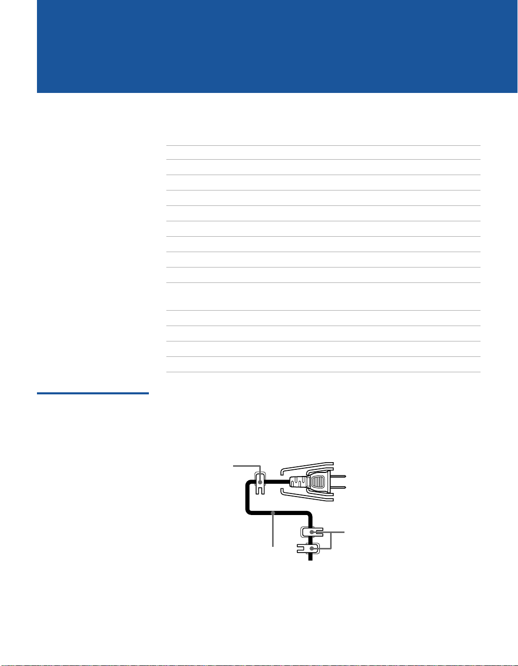
Note About the AC Power Cord
The AC power cord is attached to the rear of the TV with hooks. Use
caution when removing the AC plug from its holder . Gently slide the
cord in the upward direction without removing the cord from the two
lower hooks.
You can detach
the cord from
this hook
Do not remove the cord from the
hook(s). (The KV-36FS 12, 36FS16,
AC Power cord
36FV16 and 36FV26 models have
only one, larger hook.
7
Installing the TV
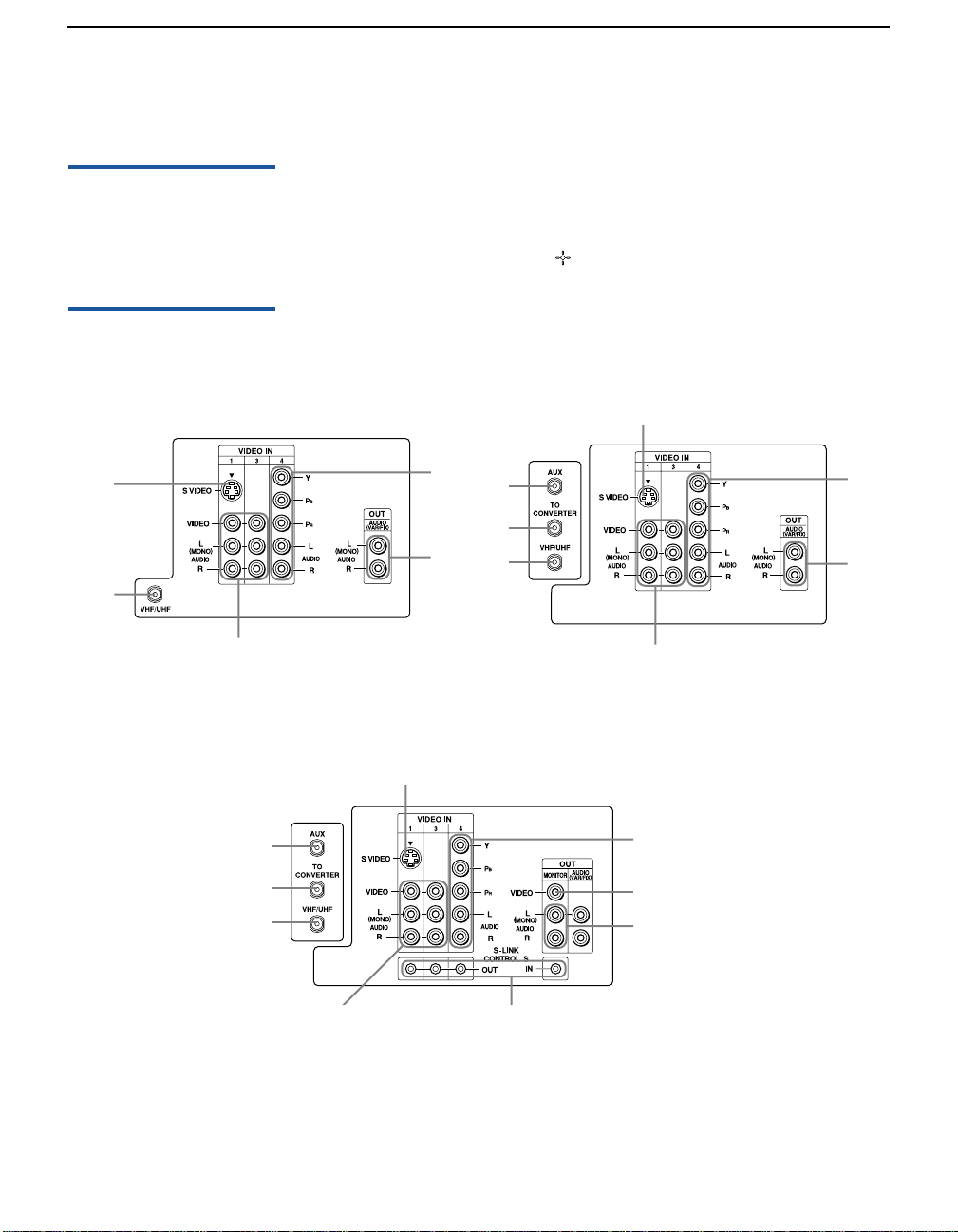
TV Controls and Connectors
Front Panel Menu Controls
TV Rear Panel
Model KV-36FS12 Model KV-36FS16
4
3
6
The front panel menu controls allow access to the on-screen menus
without the use of a remote control. Pressing the
MENU button brings
up the on-screen menus. The arrow buttons (Vv) move the on-screen
cursor in the menus and the ( ) button selects the menu item.
4
9
7
1
2
3
6
9
7
Models KV-32FV16, 32FV26, 36FV16 and 36FV26
4
1
2
3
6
8
9
5
7
8

Installing the TV
Back Panel Descriptions
Connection Description
1AUX
(except
KV-36FS12)
Allows you to view l ocal and c able cha nnels if yo ur cable
provider does not feature local channels. You can switch
between local and cable channels easily by pressing ANT
on the remote control. Devices connected to the AUX
input cannot be viewed in PIP.
2TO CONVERTER
(except
KV-36FS12)
This is a VHF/UHF out jack that lets you set up your TV
to switch between scrambled channels (through a cable
box) and normal c able channels (CATV). Use this jack
instead of a splitter to get better picture quality when
needing to switch between scrambled and unscrambled
cable channels.
3VHF/UHF Connects to your VHF /U H F ant e nn a or cable.
4S VIDEO Connects to the S VIDEO OUT jack of your VCR or other
S VIDEO-equipped video component. Provides better
picture quality than the VHF/UHF jacks or the V ideo IN
jack.
5MONITOR OUT
(except models
KV-36FS12 and
Lets you record the program you are watching to a VCR.
When two VCRs are connected (see page 17), you can
use your TV as a monitor for tape-to-tape editing.
36FS16)
6AUDIO (L/R)/
VIDEO
Connects to the audio and video OU T jacks on your VCR
or other video component. A third video input (VIDEO
2) is located on the front panel of the TV. The Audio and
Video IN jacks provide better picture quality than the
VHF/UHF jack.
7AUDIO OUT
(VAR/FIX)
L (MONO)/R
8S-LINK
CONTROL S IN/OUT
(except models
Connects to the left a nd ri ght a udio inputs of your audio
or video component. You can use these outputs to listen
to your TV’s audio through your stereo system .
Allows the TV to receive (IN) and send (OUT) remote
control signals to other Sony infr ared-contr olled audio or
video components.
KV-36FS12 and
36FS16)
B, PR, L, R Connects to your DV D pla ye r ’s or Digital Set-top box’s
9Y, P
component video (Y, P
B, PR) and audio (L/R) jacks.
9

Installing the TV
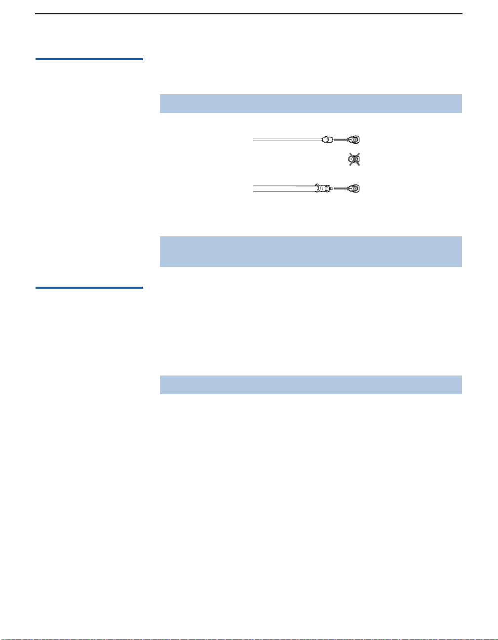
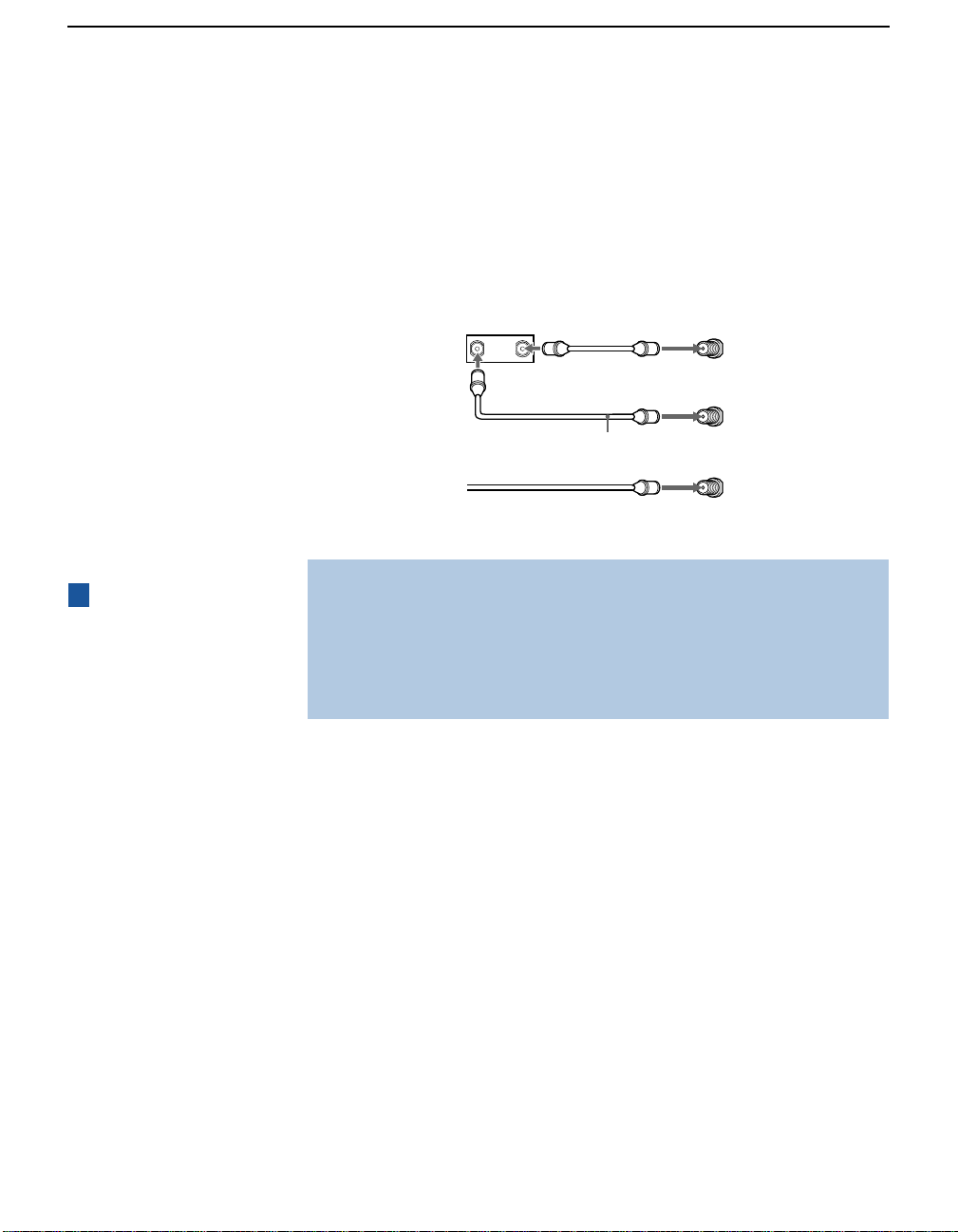
Connect ing a Cable or Antenna
Connecting Directly to Cable or an Antenna
The connection you choose depends on the cable found in your
home. Newer homes are equipped with standard coaxial cable (see
A); older homes probably have 300-ohm, twin-lead cable (see B);
other homes may contain both (see
A VHF Only or VHF/UHF or Cable
75-ohm
coaxial
cable
B VHF Only or UHF Only or VHF/UHF
300-ohm twin
lead cable
Antenna connector
C VHF and UHF
75-ohm
coaxial cable
C).
VHF/UHF
Rear of TV
VHF/UHF
Rear of TV
VHF/UHF
Rear of TV
U/V Mixer
(not supplied)
10
300-ohm twin
lead cable
Installing the TV
Cable and Antenna If your cable provider does not feature local channels, you may find
this set up convenient.
✍ This connection applies to all models except KV-36FS12.
Basic Cable Box Connections
CATV cable
(No connection to
TO CONVERTER)
Antenna cable
Select CABLE or antenna (ANT) mode by pressing
AUX
Rear of TV
TO CONVERTER
VHF/UHF
ANT on the remote
control.
✍ To receive channels with an antenna, you need to turn your Cable to OFF (see
page 40) and perform the Auto Program function (see page41).
Cable Box and Ca b le
This is the preferred basic cable TV hookup to use if:
❑ Your cable TV company scrambles some channels, but not all of
them (pay channels vs. regular cable channels), and you need to
use a cable box, and
❑ You want to enjoy the PIP feature.
✍ This connection applies to all models except KV-36FS12.
With this setup you can:
❑ Use the TV remote control to change channels using your cable
box when the signal is scrambled.
❑ Use the TV remote control to change channels using your TV
when the signal is not scrambled. (Your TV’s tuner provides a
better signal than the cable box.)
❑ Use the PIP feature. (When all channels are routed through your
cable box, only one signal is sent to the TV , s o you cannot use the
PIP feature.)
(Continued on the next page)
11
Installing the TV
1 Connect the Cable TV cable to the TV’s VH F/UHF jack.
2 Using a coaxial cable, connect the TV’s TO CONVERTER jack to
the cable box’s IN jack. The TV’s internal converter allows you to
switch betweeen unscrambled signals coming straight into the
TV and scrambled signals coming in through the cable box,
eliminating the need for an external splitter.
3 Using a coaxi al cable, connect the cable box’s OUT jack to the
TV’s AUX jack.
Cable box
IN
75-ohm coaxial cable (not supplied)
75-ohm coaxial cable
(not supplied)
3
OUT
TO CONVERTER
2
1
CATV cable (unscrambled channels)
AUX
VHF/UHF
R
e
a
r
o
f
T
V
z
Pressing ANT on the
remote control switches
between the channels
coming in through the
cable box (scrambled) and
those coming directly to
the TV (unscrambled).
✍ Your Sony remote control can be programmed to operate your cable box (see
“Programming the Remote Control” on page 52).
✍ To change chann els using the cable bo x , set yo ur TV to chann el 3 o r 4. Setting
the Channel Fix feature in the Channel menu (see “Using the Chan nel Menu”
on page 40) ensures that you do not accidentally switch the channels using
your TV.
12
Installing the TV
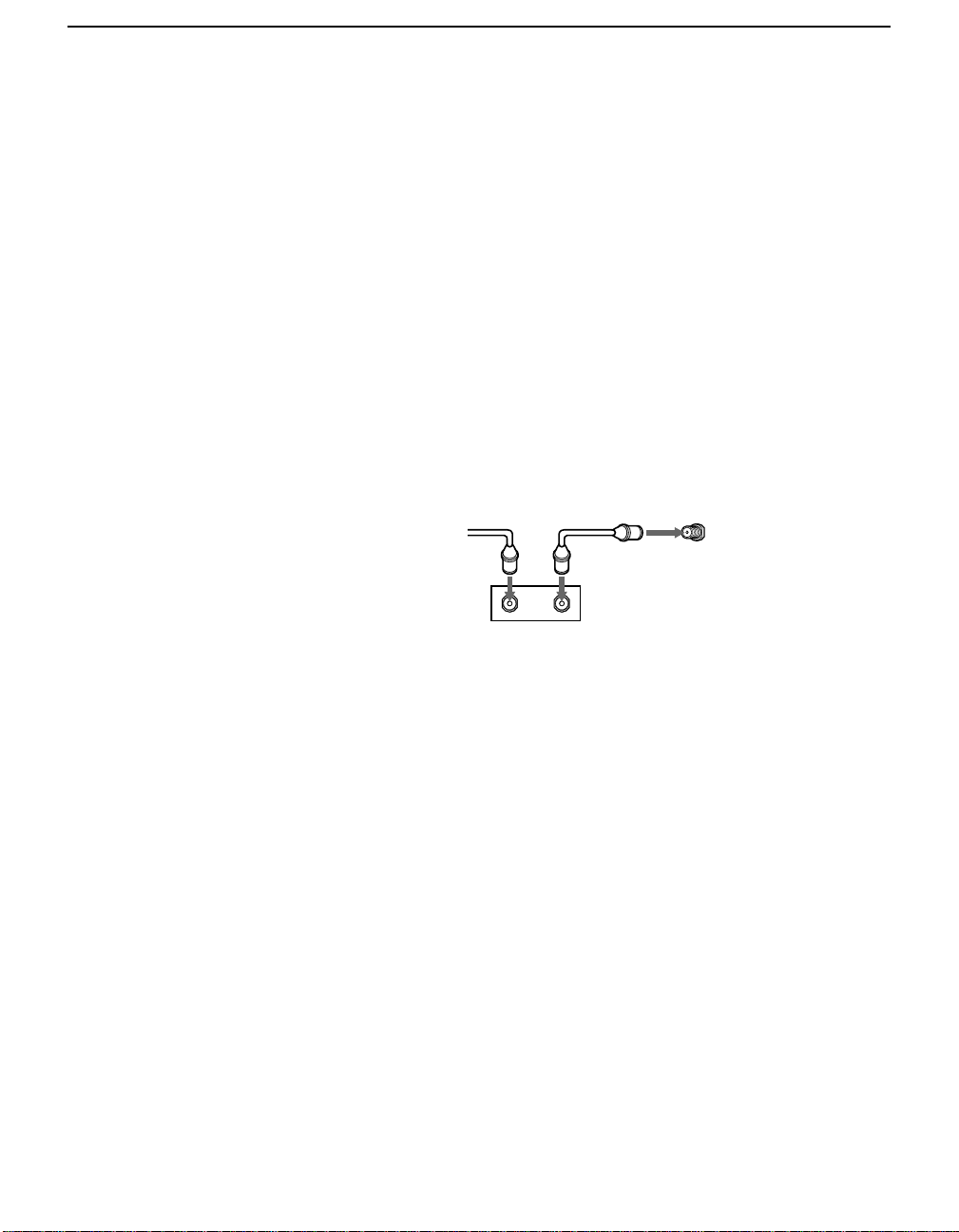
Cable Box only
Use this hookup if:
❑ You subscribe to a cable TV system that scrambles or encodes all
signals, requiring a cable box to view all channels, and
❑ You do not intend to hook up any other audio or video
equipment to your TV.
When all channels are routed through your cable box, only one
unscrambled signal is sent to the TV, so you cannot use the PIP
feature. If some of your channels are scrambled, but others are not,
consider using the hookup “Cable Box and Cable” on page 11
instead.
1 Connect the coaxial connector from your cable service to the
cable box’s IN jack.
2 Using a coaxi al cable, connect the cable box’s OUT jack to the
TV’s VHF/UHF jack.
Cable
12
VHF/UHF
Rear of TV
IN
OUT
Cable box
13

Installing the TV
Connecting a VCR and Cable
Use this hookup if:
❑ You subscribe to a cable TV system that does not require a cable
box.
1 Connect the cable TV cable to the VCR’s IN jack.
2 Using a coaxial cable, connect the VCR’s OUT jack to the TV’s
VHF/UHF jack.
3 Using an A/V cable, connect the VCR’s Audio and Video OUT
jacks to the TV’s Audio and Video IN jacks.
✍ If your VCR has an S VIDEO jack: For best picture quality, use an S VIDEO
connection instead of the yellow video cable on your combined A/V cable.
Using an S VIDEO cable, connect the VCR’s S VIDEO OUT jack to the TV’s
S VIDEO IN jack. S VIDEO does not provide audio, so audio cables must still be
connected to provide sound.
TV
14
Cable
Coaxial cable
VCR
AUDIO-R (red)
AUDIO-L (white)
VIDEO (yellow)
A/V cable

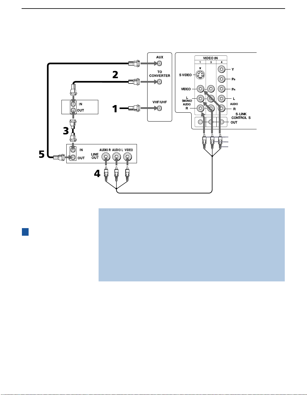
Connecting a VCR and Cable Box
Use this hookup if:
❑ Your cable TV company scrambles some channels, but not all of
them (pay channels vs. regular cable channels) and you therefore
need to use a cable box, and
❑ You want to enjoy the PIP feature.
✍ This connection applies to all models except KV-36FS12.
With this setup you can:
❑ Use the TV remote control to change cable box channels when the
signal is scrambled.
❑ Use the TV remote control to change TV channels when the
signal is not scrambled. (Your TV’s tuner provides a better signal
than the cable box.)
❑ Use the PIP feature. (When all channels are routed through the
cable box, only one signal is sent to the TV , s o you cannot use the
PIP feature.)
1 Connect the Cable TV cable to the TV’s VH F/UHF jack.
2 Using a coaxial cable, connect the TV’s TO CONVERTER jack to
the cable box’s IN jack. The TV’s internal converter allows you to
switch between unscrambled signals coming straight into the TV
and scrambled signals coming in through the cable box. This
eliminates the need for an external splitter.
Installing the TV
3 Using a coaxi al cable, connect the cable box’s OUT jack to the
VCR’s IN jack.
4 Using an A/V cable, connect the VCR’s Audio and Video OUT
jacks to the TV’s Audio and Video IN jacks.
5 Using a coaxial cable, connect the VCR’s OUT jack to the TV’s
AUX jack.
✍ To view scrambled channels, set your TV to AUX 3 or 4 (depending on your
cable box output). Change channels using your cable box.
(Continued on the next page)
15
Installing the TV
Coaxial
cable
Cable box
Coaxial
cable
VCR
TV
Cable
AUDIO-R (red)
AUDIO-L (white)
VIDEO (yellow)
A/V cable
z
Pressing the ANT
button on the remote
control switches between
the channels coming in
through the cabl e box
(scrambled) and those
coming directly to the TV
(unscrambled).
16
✍ If your VCR has an S VIDEO jack: For best picture quality, use an S VIDEO
connection instead of the yellow video cable on your combined A/V cable.
Using an S VIDEO cable, connect the VCR’s S VIDEO OUT jack to the TV’s S
VIDEO IN jack. S VIDEO does not provide audio, so audio cables must still be
connected to provide sound.
✍ To change chann els using the VCR or cable bo x, s et your TV to ch ann el 3 or 4.
Setting the Channel Fix feature in the Channel menu (see “Using the Channel
Menu” on page 40) ensures you do not accidentally switch the channels using
your TV.
 Loading...