

SONY KV-29X5A, KV-29X5B, KV-29X5D, KV-29X5E, KV-29X5K Service Manual
...
SELF-DIAGNOSTIC FUNCTION
MICROFILM
SERVICE MANUAL FE-1 CHASSIS
MODEL
COMMANDER DEST CHASSIS NO.
KV-29X5A
KV-29X5B
KV-29X5D
KV-29X5E
RM-883 Italian SCC-Q06A-A
RM-883 French SCC-Q02A-A
RM-883 AEP SCC-Q04A-A
RM-883 Spanish SCC-Q05A-A
MODEL
KV-29X5K
KV-29X5L
KV-29X5R
KV-29X5U
COMMANDER DEST CHASSIS NO.
RM-883 OIRT SCC-Q03A-A
RM-883 Irish SCC-Q07A-A
RM-883 OIRT SCC-Q03B-A
RM-883 UK SCC-Q01A-A
/
MENU
PROGR
RM-883
TRINITRON
1
®
COLOR TV
®
KV-29X5
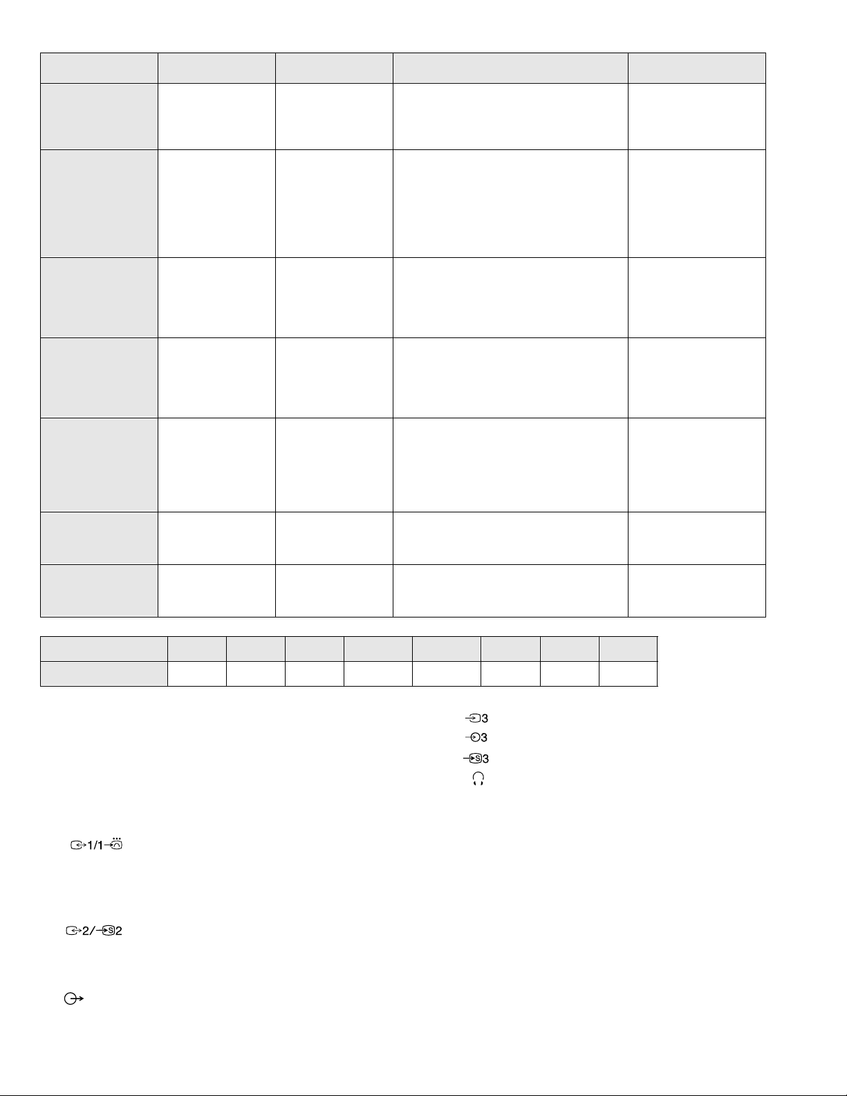
ITEM MODEL T elevision System Stereo System Channel Coverage Color System
Italian B/G/H GERMAN Stereo
French B/G/H, D/K, L, I GERMAN/NICAM
Stereo
AEP B/G/H, D/K GERMAN Stereo
Spanish B/G/H, D/K GERMAN/NICAM
OIRT B/G/H, D/K
Stereo
KV-29X5K
GERMAN/NICAM
Stereo
KV-29X5R
GERMAN Stereo
ITALIA VHF : A-H2 (C) UHF : 21-69 PAL
B/G/H VHF : E2-E12 UHF : E21-E69
CABLE TV (1) : S1-S41
CABLE TV (2) : S01-S05, M1-M10, U1-U10
L VHF : F02-F10 UHF : F21-F60
CABLE : B-Q B/G/H VHF : E2-E12
UHF : E21-E69
CABLE TV (1) : S1-S41
CABLE TV (2) : S01-S05, M1-M10, U1-U10
ITALIA VHF : A-H2 (C) UHF : 21-69
I UHF : B21-B69
PAL B/G/H VHF : E2-E12 UHF : E21-E69
CABLE TV (1) : S1-S41
CABLE TV (2) : S01-S05, M1-M10, U1-U10
ITALIA VHF : A-H2 (C) UHF : 21-69
D/K VHF : R01-R12 UHF : R21-R69
PAL B/G VHF : E2-E12 UHF : E21-E69
CABLE TV (1) : S1-S41
CABLE TV (2) : S01-S05, M1-M10, U1-U10
ITALIA VHF : A-H2 (C) UHF : 21-69
D/K VHF : R01-R12 UHF : R21-R69
B/G/H VHF : E2-E12 UHF : E21-E69
CABLE TV (1) : S1-S41
D/K VHF : R01-R12 UHF : R21-R69
PAL
NTSC4.43, NTSC3.58
(VIDEO IN)
PAL, SECAM
NTSC4.43, NTSC3.58
(VIDEO IN)
PAL, SECAM
NTSC4.43, NTSC3.58
(VIDEO IN)
PAL, SECAM
NTSC4.43, NTSC3.58
(VIDEO IN)
PAL, SECAM
NTSC4.43, NTSC3.58
(VIDEO IN)
Irish I NICAM Stereo
UK I NICAM Stereo UHF : B21-B69
MODEL 29X5A 29X5B 29X5D 29X5E 29X5K 29X5L 29X5R 29X5U
Power Consumption 100.1 W 108 W 108 W 108 W 108 W 158.5 W 108 W 158.5 W
[PICTURE TUBE] Super Trinitron
Approx. 72cm (29 inches)
(Approx. 68 cm picture measured
diagonally)
110 degree deflection
VHF : A-H2 VHF : E02-E12
CABLE CHANNELS S1-S20
HYPERBAND S21-S46
[FRONT]
Video input - phono jack
Audio inputs - phono jacks
S Video input 4 pin DIN
Headphone jacks : stereo minijack
Input/Output Terminals
Sound output 2 x 20W (Music Power)
[REAR]
21-pin Euro connector (CENELEC standard).
- Inputs for Audio and Vide o signals.
- Inputs for RGB.
- Outputs of TV Video and Audio signals.
21-pin Euro connector.
- i nputs for Audio and Video signals.
- i nputs for S Video.
- outputs for Audio and Video signals (selectable).
Phono Jack
- Outputs for Audio Signals
Power requirements 220 - 240V
Dimensions Approx 676x557x525mm
Weight Approx 43.5kg
Supplied accessories RM-883 Remote Commander (1)
IEC designated R6 battery (1)
Other features NICAM*, FASTEXT, TOPTEXT
(KV-29X5B/29X5E/29X5L/29X5U only)
*
[RM-883]
Remote control system infrared control
Power requirements 1.5V dc
1 battery IEC designation
R6 (size AA)
Dimensions Approx 65x225x21mm (w/h/d)
Weight Approx 157g (Not including batt e ry)
PAL, SECAM
NTSC4.43, NTSC3.58
(VIDEO IN)
PAL, SECAM
NTSC4.43, NTSC3.58
(VIDEO IN)
Design and specifications are subject to change withou t notice.
2
KV-29X5
ASA
T
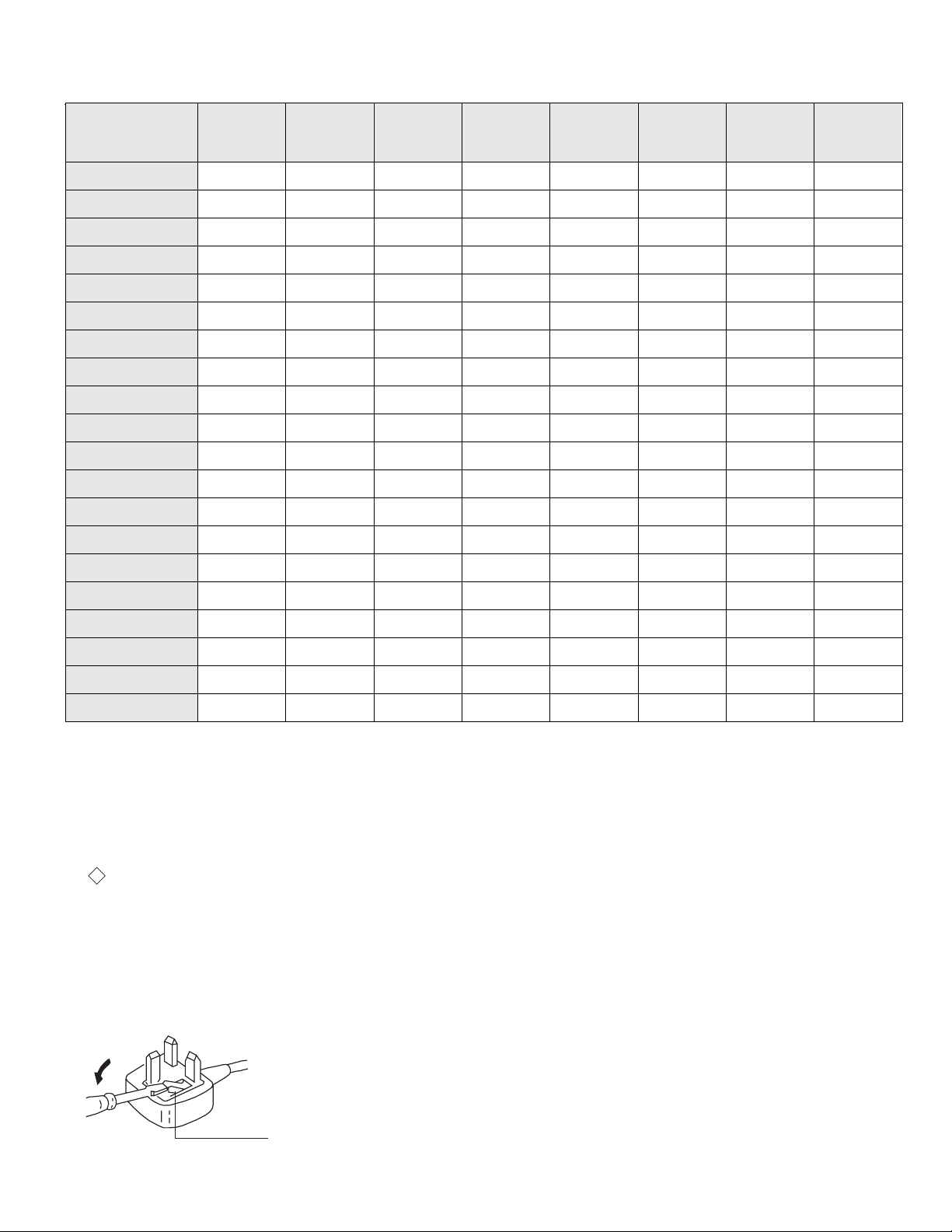
How to replace the fuse.
Open the fuse compartment with
a screwdriver blade and replace
the fuse.
FUSE
Model Name
Item
Pal Comb OFF OFF OFF OFF OFF OFF OFF OFF
PIP OFF OFF OFF OFF OFF OFF OFF OFF
RGB Priority OFF ON ON ON OFF OFF OFF OFF
Woofer Box OFF OFF OFF OFF OFF OFF OFF OFF
Scart 1 ON ON ON ON ON ON ON ON
Scart 2 ON ON ON ON ON ON ON ON
Front in (3) ON ON ON ON ON ON ON ON
Scart 4 OFF OFF OFF OFF OFF OFF OFF OFF
Projector OFF OFF OFF OFF OFF OFF OFF OFF
AKB in 16:9 mode ON ON ON ON ON ON ON ON
Norm B/G ON ON ON ON ON OFF ON OFF
Norm I OFF OFF OFF OFF OFF ON ON OFF
KV-29X5A KV-29X5B KV-29X5D KV-29X5E KV-29X5K KV-29X5L KV-29X5R KV -29X5U
Norm D/K OFF ON ON ON ON OFF ON OFF
Norm AUS OFF OFF OFF OFF OFF OFF OFF OFF
Norm L OFF ON OFF OFF OFF OFF OFF OFF
Norm SAT OFF OFF OFF OFF OFF OFF OFF OFF
Norm M OFF OFF OFF OFF OFF OFF OFF OFF
Teletext ON ON ON ON ON ON ON ON
Nicam Stereo OFF ON OFF ON ON ON OFF ON
Language Preset Italian French German Spanish OIRT English OIRT English
WARNING (KV-29X5L / KV-29X5U only)
The flexible m ains lead is supplied connected to a B.S. 1363 fused plug
having a fuse of 5 AMP capacity. Should the fuse need to be replace d ,
use a 5 AMP FUSE approved by ASTA to BS 1362, ie one that carries the
the mark.
IF THE PLUG SUPPLIED WITH THIS APPLIANCE IS NOT SUITABLE
FOR THE OUTLET SOCKETS IN YOUR HOME, IT SHOULD BE CUT
OFF AND AN APPROPRIATE PLUG FITTED. THE PLUG SEVERED
FROM THE MAINS LEAD MUST BE DESTROYED AS A PLUG WITH
BARED WIRES IS DANGEROUS IF ENGAGED IN A LIVE OUTLET
SOCKET.
When an alternati ve type of plug is used it should be fitted wi th a 5 AMP
FUSE, otherwise the circuit shoul d be protected by a 5 AMP FUSE at the
distribution board.
3
KV-29X5
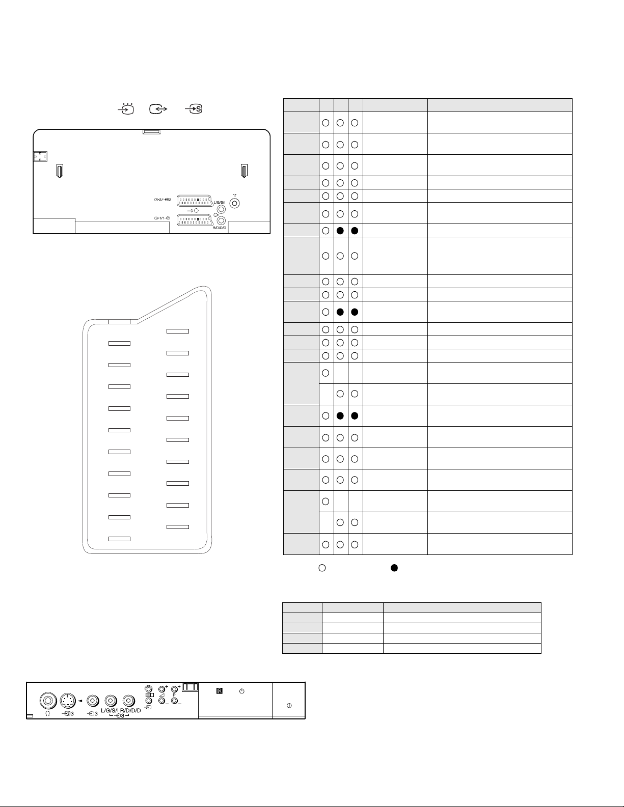
21 pin connector ( 1, 2 / 2 )
21
20
19
18
17
16
15
14
13
12
11
10
9
8
7
6
5
4
3
2
1
Pin No 1 2 4 Signal Signal level
1 Audio output B
2
3
4 Ground (audio)
5 Ground (blue)
6 Audio input A
7 Blue input 0.7 +/- 3dB, 75 ohms positive
8 Function select
9 Ground (green)
10 Open
11 Green Green signal : 0.7 +/- 3dB, 75 ohms,
12 Open
13 Ground (red)
14 Ground (blanking)
15
_ (S signal Chroma
16 Blanking input
17 Ground (video
18 Ground (video
19 Video output 1V +/- 3dB, 75ohms, positive sync 0.3V
20
_ Video input
21 Common ground
(right)
Audio output B
(right)
Audio output A
(left)
(left)
(AV control)
_ _ Red input 0.7 +/- 3dB, 75 ohms, positive
input)
(Ys signal)
output)
input)
_ _ Video input 1V +/- 3dB, 75ohms, positive sync 0.3V
Y (S signal)
(plug, shield)
Standard level : 0.5V rms
Output impedence : Less than 1kohm*
Standard level : 0.5V rms
Output impedence : More than 10kohm*
Standard level : 0.5V rms
Output impedence : Less than 1kohm*
Standard level : 0.5V rms
Output impedence : More than 10kohm*
High state (9.5-12V) : Part mode
Low state (0-2V) : TV mode
Input impedence : More than 10K ohms
Input capacitance : Less than 2nF
positive
0.3 +/- 3dB, 75 ohms, positive
High state (1-3V) Low state (0-0.4V)
Input impedence : 75 ohms
(-3+10dB)
(-3+10dB)
1V +/- 3dB, 75ohms, positive sync 0.3V
(-3+10dB)
Connected Not Connected (open) * at 20Hz - 20kHz
Pin No Signal Signal level
1 Ground
2 Ground
3 Y (S signal) input 1V+/- 3dB 75 ohm, positive Sync 0.3V -3/+10dB
4 C (S signal) input 0.3V+/- 3dB 75 ohm, positive Sync
4

KV-29X5
TABLE OF CONTENTS
Section Title Page Section Title Page
1. GENERAL
5. DIAGRAMS
Overview of TV buttons .....................6
Adjusting the Picture and Sound .....................7
Using the Sleep Timer .....................8
Viewing Teletext .....................8
Exchanging Programme Positions .....................9
Manually T u nin g the TV ................... ..9
Fine-Tuning Channels .....................10
Using Optional Equipment .....................10
Trouble sho oting/Specific a tio ns .....................11
2. DISASSEMBLY
2-1. Rear Cover Removal .....................12
2-2. Chassi s Assy Removal .....................12
2-3. Service Position .....................12
2-4. S1 Board Re moval ................... ..13
2-5. H1 Board Removal .....................13
2-6. Picture Tube Removal .....................14
2-7. Removal and Replacement of the
Main - Bracket Bottom Plates .....................15
3. SET-UP ADJUSTMENTS
3-1. Beam Landing .....................16
3-2. Convergence .....................17
3-3. Screen [G2] White Balance .....................19
3-4. Focus .....................19
5-1. Block Diagram .....................25
5-2. Circuit Board Location .....................32
5-3. Schematic Diagrams and
Printed Wiring Boards .....................32
* S1 Board .....................34
* A Board .....................41
* VMBoard .....................46
* C Board .....................49
* H 1 Boa rd .....................51
5-4. Semicondu c tors .....................53
5-5. IC Blocks .....................55
6. EXPLODED VIEWS
6-1. Chassis .................... .56
6-2. Picture Tube .....................57
7. ELECTRICAL PARTS LIST .....................58
4. CIRCUIT ADJUSTMENTS
4-1. Electrical Adjustments .....................20
4-2. Test Mode 2 .....................23
4-3. FE-1 Self Diagnostic Software .....................24
CAUTION
SHORT CIRCUIT THE ANODE OF THE PICTURE TUBE AND THE
ANODE CAP TO THE METAL CHASSIS, CRT SHIELD, OR THE
CARBON PAINTED ON THE CRT, AFTER REMOVAL OF THE
ANODE CAP
WARNING !!
AN ISOLATING TRANSFORMER SHOULD BE USED DURING ANY
SERVICE WORK TO AVOID POSSIBLE SHOCK HAZARD DUE TO
LIVE CHASSIS. THE CHASSIS OF THIS RECEIVER IS DIRECTLY
CONNECTED TO THE POWER LINE.
SAFETY-RELATED COMPONENT WARNING !!
COMPONENTS IDENTIFIED BY SHADING AND MARKED ON
THE SCHEMATIC DIAGRAMS, EXPLODED VIEWS AND IN THE
PARTS LIST ARE CRITICAL FOR SAFE OPERATION. REPLACE
THESE COMPONENTS WITH SONY PARTS WHOSE P ART NUMBERS
APPEAR AS SHOWN IN THIS MANUAL OR IN SUPPLEMENTS
PUBLISHED BY SONY.
ATTENTION
APRES AVOIR DECONNECTE LE CAP DE’LANODE,
COURT-CIRCUITER L’ ANODE DU TUBE CATHODIQUE ET
CELUI DE L’ANODE DU CAP AU CHASSIS METALLIQUE
DE L’APPAREIL, OU AU COUCHE DE CARBONE PEINTE
SUR LE TUBE CATHODIQUE OU AU BLINDAGE DU TUBE
CATHODIQUE.
ATTENTION !!
AFIN D’EVITER TOUT RISQUE D’ELECTROCUTION PROVENANT
D’UN CHÁSSIS SOUS TENTION, UN TRANSFORMATEUR
D’ISOLEMENT DOIT ETRE UTILISÈ LORS DE TOUT DÈPANNAGE.
LE CHÁSSIS DE CE RÈCEPTEUR EST DIRECTMENT RACCORDÈ
Á L’ALIMENTATION SECTEUR.
ATTENTION AUX COMPOSANTS RELATIFS Á LA
SÈCURITÈ !!
LES COMPOSANTS IDENTIFIÈS PAR UNE TRAME ET PAR UNE
MARQUE SUR LES SCHÈMAS DE PRINCIPE, LES VUES
EXPLOSÈES ET LES LISTES DE PIECES SONT D’UNE IMPORTANCE
CRITIQUE POUR LA SÈCURITÈ DU FONCTIONNEMENT, NE LES
REMPLACER QUE PAR DES COMPSANTS SONY DONT LE NUMÈRO
DE PIÈCE EST INDIQUÈ DANS LE PRÈSENT MANUEL OU DANS
DES SUPPLÈMENTS PUBLIÈS PAR SONY.
5
SECTION 1 GENERAL
The operating instructions mentioned here are partial abstracts
from the Operating Manual. The page numbers of the Operating
Instruction Manual remain as in the manual.
Basic TV Features
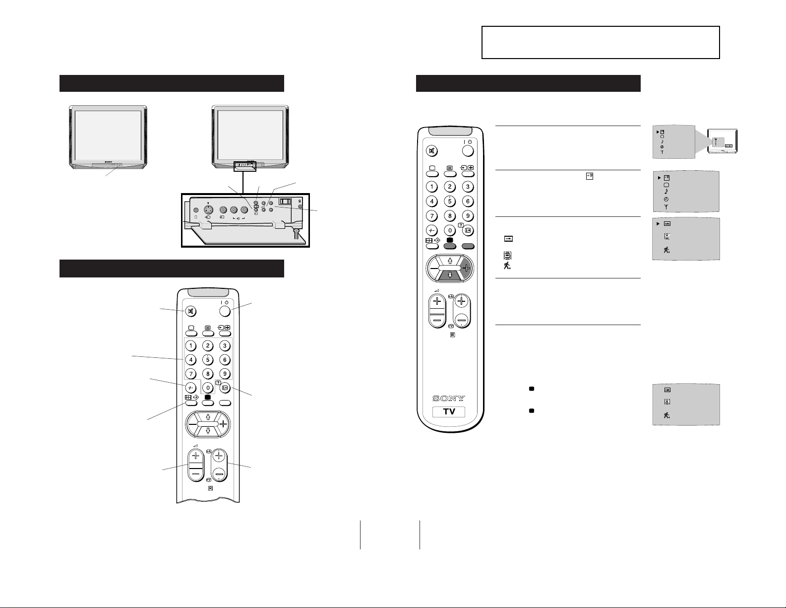
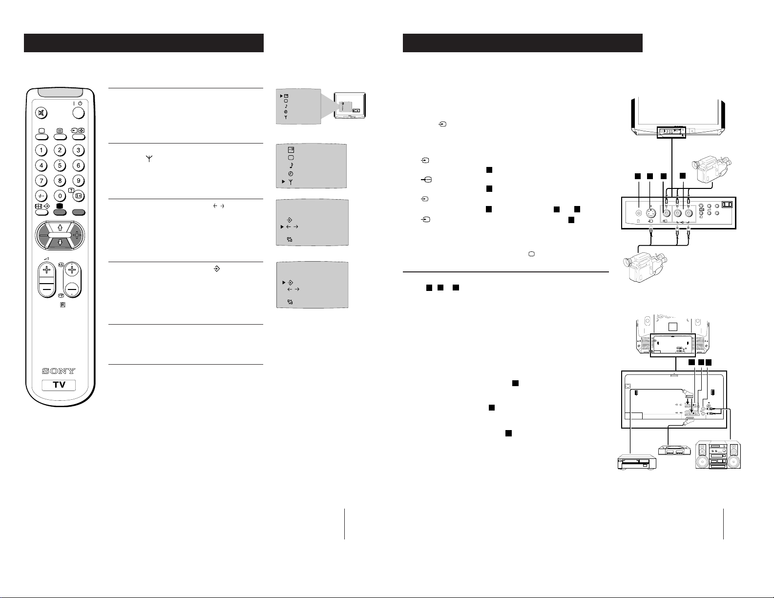
Overview of TV Buttons
Additional TV Features
Using Select Mode
You can select different preset picture and sound modes.
SELEC
T
OFF
SELEC
T
OFF
SELEC
T
OFF
OK
On/Off Switch.
Video Input Button.
(selects input signals
from VCR etc.).
MONO
L/G/S/I R/D/D/D
s
2
s
2
MONO
L/G/S/I R/D/D/D
2
2
++
P
__
Auto Tune
Button
++
P
__
Volume Control Buttons.
Programme Up or
Down Buttons.
(selects TV channels).
/
MENU
1 Press the MENU button on the remote control to
display the menu on the TV screen.
2 With the cursor pointing at the
TV screen as shown, press the yellow button.
symbol on the
SELEC
T
3 Press the blue button to select the desired mode:
reverts to settings made in “Adjusting the
Picture and Sound” sections of the manual
for films
Overview of Remote Control Buttons
6
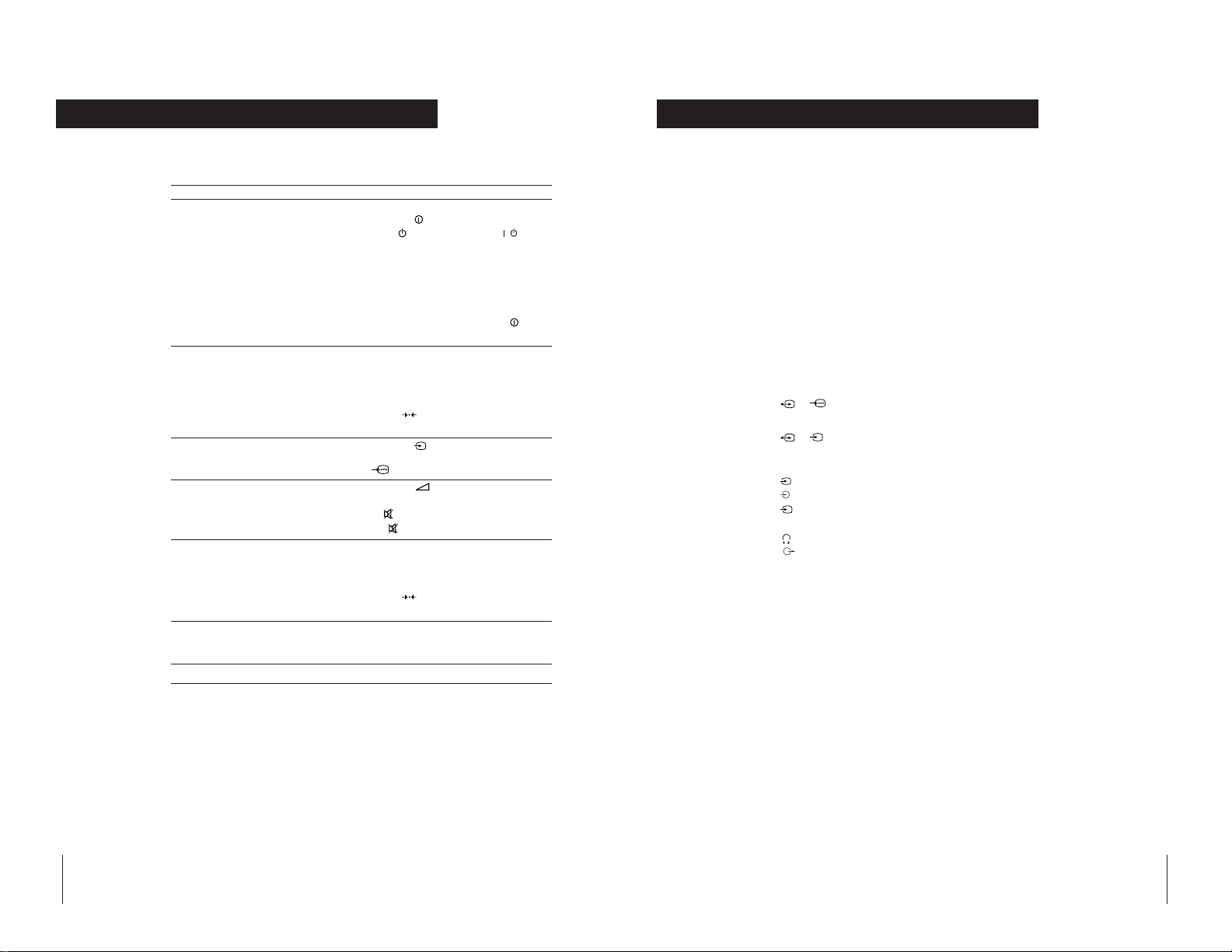
To Mute Sound
Press to mute TV sound. Press again
to restore the sound.
To Select Channels
Press to select channels.
For double-digit programme
numbers, e.g. 23, press -/-- first,
then the buttons 2 and 3.
To Change Screen Format
Press to view programmes in 16:9
mode.
Press again to return to 4:3 mode.
To Adjust TV Volume
Press to adjust the volume of the TV.
/
MENU
PROGR
RM-883
To Temporarily Switch Off TV
Press to temporarily switch off TV. Press
again to switch on TV from standby
mode.
To save energy we recommend switching off
completely when TV is not in use.
NOTE: After 15 -30 minutes without a
TV signal and without any button being
pressed, the TV switches automatically
into standby mode.
To Reveal On Screen Information
Press to reveal all on-screen indications.
Press again to cancel.
To Select Channels
Press to select channels.
PROGR
RM-883
for programmes broadcast live
4 Press the MENU button to remove the menu
display from the TV screen.
Note: The mode selected in step 3 is now stored.
Changing Modes Quickly
1
Press the button on the remote control to display
the three different modes.
2 Press the button again to select your desired
mode.
7
8
Additional TV Features
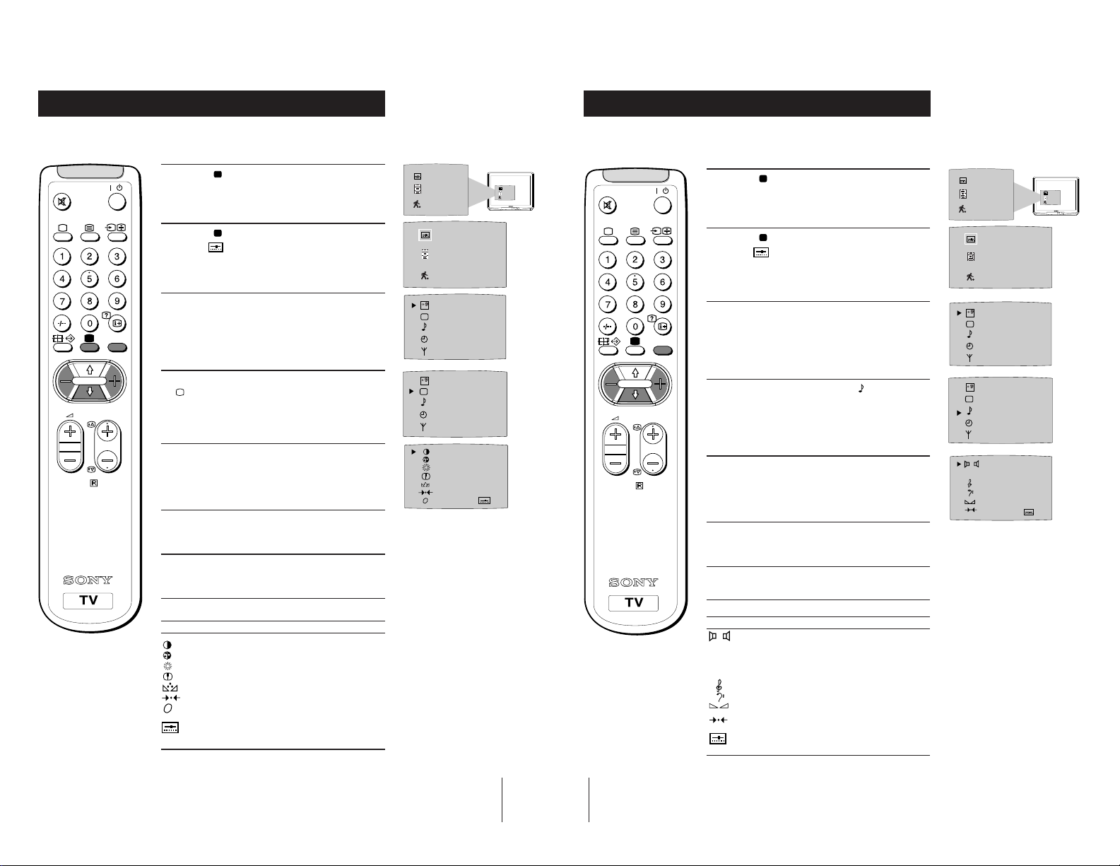
Adjusting the Picture
Additional TV Features
Adjusting the Sound
Although the picture is adjusted at the factory, you can modify it to suit your own
requirement.
1 Press the button on the remote control to
/
display the three different modes on the TV
screen.
2 Press the button to highlight the user mode
as shown.
MENU
symbol
3 Press the MENU button to display the menu on
the TV screen.
4 Press the blue button on the control to select the
symbol on the TV screen then press the yellow
PROGR
7
button.
5 Press the blue button to select the item you wish
to change (see below).
RM-883
6 Press the red or yellow button to alter the selected
item.
7 Press the MENU
display from the TV screen.
button to remove the menu
SELEC
T
SELEC
T
OFF
OFF
IIIIIIIIIIIIIII- - - - - IIIIIIIIIIIIIII- - - - - IIIIIIIIIIIIIII- - - - - -
IIIIIIIIIIIIIII- - - - - IIIIIIIIIIIIIII- - - - - -
0
Although the sound is adjusted at the factory, you can modify it to suit your own
requirement.
1 Press the button on the remote control to
/
display the three different modes on the TV
screen.
2 Press the button to highlight the user mode
symbol
as shown.
3 Press the MENU button to display the menu on
the TV screen.
MENU
4 Press the blue button to select the symbol on the
TV screen then press the yellow button.
PROGR
5 Press the blue button to select the item you wish to
RM-883
change (see below).
6 Press the red or yellow button to alter the selected
item.
7 Press the MENU
display from the TV screen.
button to remove the menu
DSP
SELEC
T
SELEC
T
OFF
OFF
MONO STEREO
ON OFF
IIIIIIIIIIIIIIIIIIIIIII - - - - - IIIIIIIIIIIIIIIII - - - - - - - - IIIIIIIIIIIIIII- -
IIIIIIIIIIIIIII
Symbol Item
• Contrast
• Colour
• Brightness
• Sharpness
• Hue control (only for NTSC video signals)
• Reset - resets to factory preset picture level
• Picture rotation - adjusts picture tilt
• Represents the mode selected in the “Using
(only for KV-29X5U model)
Select Mode” section.
Symbol Item
• Mono sound/Stereo sound
DSP • On/Off (digital sound processor)
9
10
A: Channel 1 sound/B: Channel 2 sound
(to select your desired language from a
dual sound broadcast)
• Treble
• Bass
• Balance
• Reset (resets to factory preset sound
level)
• Represents the mode selected in the “Using
Select Mode” section of the manual.
Additional TV Features
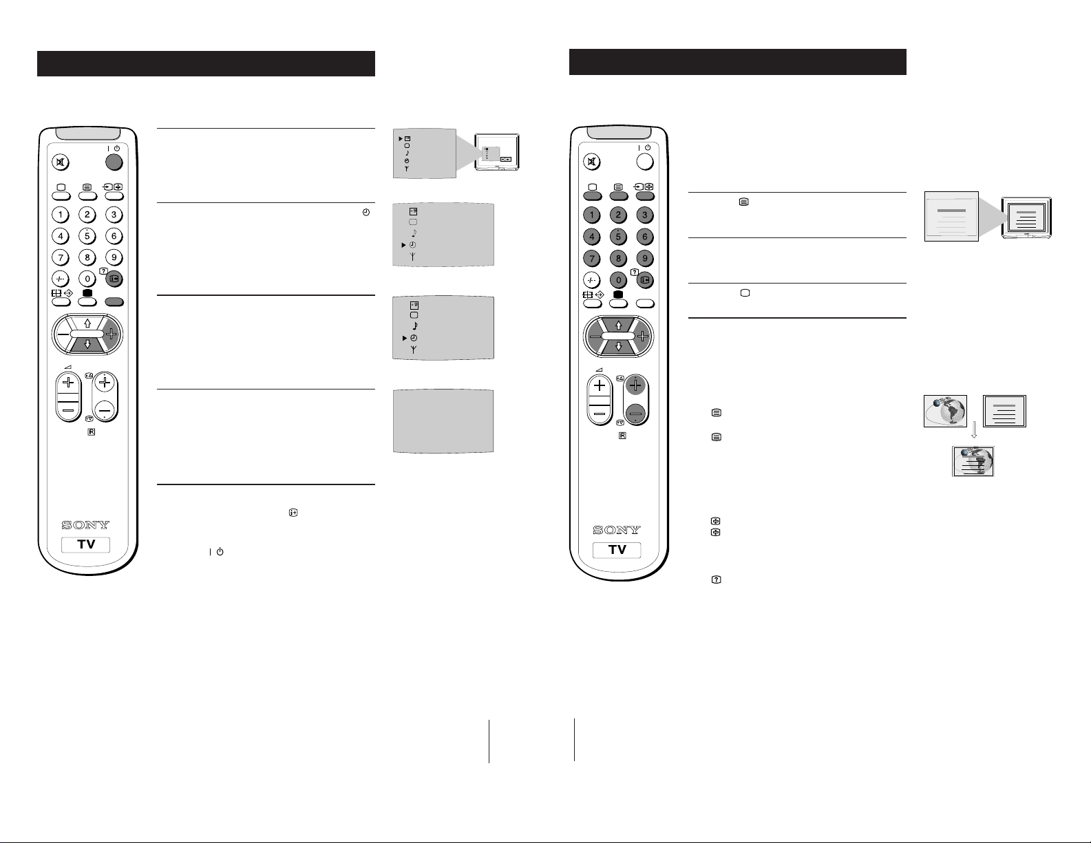
Using the Sleep Timer
Additional TV Features
Viewing Teletext
The TV may be set to switch automatically to the standby mode after a length of time
chosen by you. You may set the time in 15 minute steps up to 4 hours.
1 Press the MENU button on the remote control to
/
display the menu on the TV screen.
2 Press the blue button on the control to select the
symbol on the TV screen, then press the yellow
button.
MENU
PROGR
8
RM-883
3 Press the yellow button repeatedly until the
required amount of time delay appears on the
screen.
4 Once the time delay has been selected, press the
MENU button to remove the on-screen display.
One minute before standby, the display shown
appears on the screen.
Notes:
• When watching TV, press the
time remaining.
• To return to normal operation from standby mode,
press the
button.
button to display
SELEC
T
SELEC
SELEC
0:59
Teletext is an information service transmitted by most TV stations.
Selecting Teletext
SELEC
T
OFF
OFF
T
OFF
T
1:00
OK
PROGR
/
MENU
Press a number button on the remote control to
1
select the channel which carries the teletext service
you wish to receive.
2 Press the button on the remote control to switch
on teletext.
3 Input three digits for the page number using the
numbered buttons on the control.
4 Press the button to switch off teletext.
Note: Teletext errors may occur if the broadcasting
signals are weak.
TELETEXT
Index
Programme
News
Sport
Weather
TELETEXT
Index
Programme
25
153
101
98
25
News
153
Sport
101
Weather
98
Using Other Teletext Functions
RM-883
To Superimpose Teletext on to the TV
once in teletext mode or twice in TV mode to
Press
superimpose teletext on to the TV screen.
again to cancel teletext mode.
Press
To Move to Next or Preceding Page
Press PROGR +/previous or next page.
on the remote control to select the
To Freeze a Teletext Page
on the control to freeze the page.
Press
again to cancel the freeze.
Press
Revealing concealed information (eg: answers
to a quiz).
to reveal information.
Press
Press again to conceal the information.
TELETEXT
Index
Programme
News
Sport
Weather
TELETEXT
Index
Programme
News
Sport
Weather
25
153
101
98
25
153
101
98
11
12
Using colour buttons to access pages (Fastext)
When the colour coded menu appears at the bottom of
a page, press the colour button (green, red, yellow or
blue) to access the corresponding page.
Additional TV Features
Additional TV Features
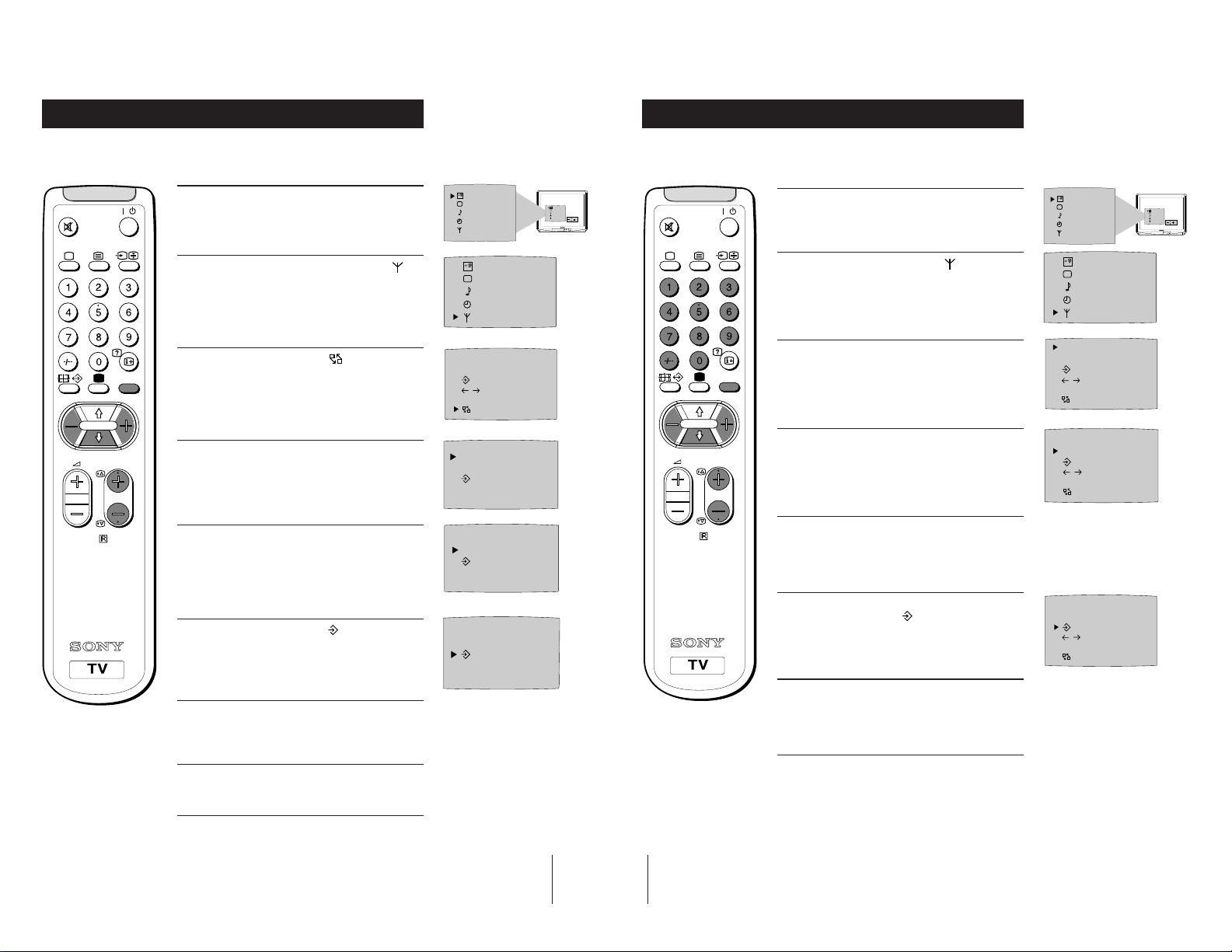
Exchanging Programme Positions
After tuning you may wish to change the order in which the channels appear on the
TV. You may wish for example to exchange the channel on programme number 8
with the channel on programme number 4.
1 Press the MENU button on the remote control.
/
2 Press the blue button on the control to select on
the TV screen, then press the yellow button.
3 Press the blue
MENU
PROGR
9
RM-883
yellow button.
4 With the cursor pointing at PROGR on the TV
screen as shown, press PROGR + or - button until
the channel you wish to rearrange appears on
screen, then press the blue button once.
5 Press the red or yellow
programme number (e.g. PROGR 04) for your
selected channel.
button to select then press the
button to select the new
SELEC
T
OFF
SELEC
T
OFF
PROGR 01
CH 05 IIIIIIIIIIIIIII- - - - - - - -
on
F
C
OO
PROGR - +
01
PROGR - +
04
Manually Tuning the TV
You have already tuned the TV to receive all available channels using the
`Automatically Tuning the TV' procedure at the start of this manual. You can
however carry out this operation manually using the following instructions.
SELEC
SELEC
T
OFF
OK
/
MENU
1 Press the MENU button on the remote control to
display the menu on the TV screen.
2 Press the blue button to select the symbol on the
TV screen then press the yellow button.
3 With the cursor pointing at PROGR on the TV
screen as shown, press PROGR + or - button on the
remote control to allocate a programme number to
the channel (eg PROGR 01). For double digit
numbers e.g. 55, press the -/-- button on the remote
control then the corresponding numbered buttons.
4 Press the blue button to select the tuning bar scale
PROGR
RM-883
then press the yellow or red button once to start the
channel search. (Yellow to search up the scale or
red to search down). When a channel is found it
appears on the TV screen.
5 If you do not wish to store this channel on the
programme number you selected, press the yellow
or red button to continue searching for the desired
channel.
T
OFF
SELEC
T
OFF
PROGR 01
CH 05 IIIIIIIIIIIIIII- - - - - - - -
on
F
COO
PROGR 01
CH 05 IIIIIIIIIIIIIII- - - - - - - -
on
F
C
OO
SELEC
T
OFF
OK
6 Press the blue
yellow button to exchange the channels.
button to select then press the
7 Repeat steps 4 to 6 if you wish to change the order
of the other channels on your TV, then press
MENU to return to normal TV screen.
8 Press the PROGR+/- button to view your selected
channels on their new programme numbers.
PROGR - +
04
13
14
6 If this is the channel you wish to store, press the
blue button to select the
then press the yellow button to store.
7 Repeat steps 3 to 6 if you wish to store more
channels then press the MENU
the menu from the TV screen.
symbol on the screen
button to remove
PROGR 01
CH 05 IIIIIIIIIIIIIII- - - - - - - -
on
F
COO
Additional TV Features
Optional Connections
Fine-Tuning Channels
If a channel is slightly off tune, you can use this fine tune procedure to obtain a better
picture reception.
1 With the channel you wish to fine-tune on the
/
MENU
PROGR
10
RM-883
screen, press the MENU button on the remote
control. The menu display appears on the TV
screen.
2 Press the blue button on the remote control to
select the
the yellow button.
3 Press the blue button to select the
the TV screen then press the red or yellow button
to adjust the tuning.
4 Press the blue button to select the symbol on the
TV screen then press the yellow button to store.
symbol on the TV screen then press
F
5 Press the MENU button to remove the menu from
the TV screen.
symbol on
SELEC
T
OFF
SELEC
T
OFF
PROGR 01
CH 05 IIIIIIIIIIIIIII- - - - - - - -
on
F
C
OO
PROGR 01
CH 05 IIIIIIIIIIIIIII- - - - - - - -
on
F
COO
Using Optional Equipment
You can connect optional audio or video equipment to your TV, such as a VCR, a
camcorder or video games as shown.
A
Front of TV
B C
s
Rear of TV
Playstation
++
MONO
P
__
L/G/S/I R/D/D/D
s
2
2
D
MONO
L/G/S/I R/D/D/D
2
S-VHS/Hi8
camcorder
s
2/
1/
2
1
8mm/Hi8
camcorder
++
P
__
2
E
G
F
L/G/S/I
R/D/D/D
Hi-Fi
SELEC
T
OFF
OK
Select and View the Input Signal
1
Connect your equipment to the designated TV socket.
2 Press
correct input symbol appears on the TV screen.
button repeatedly on your remote control until the
the
Symbol Input signals
1
• Audio/video input signal through the Euro AV
connector
• RGB input signal through the Euro AV
connector
2
• Audio/video input signal through the Euro AV
connector
s
• S video input signal through the socket B.
F
F
or the phono sockets C and
E
D
3 Switch on the connected equipment.
4 To return to normal TV picture, press the
control.
Note: To avoid picture distortion, do not connect equipment to the
B
, C or E
connectors
at the same time.
button on the remote
Additional Information
Connecting a VCR
We recommend you tune in the VCR signal to TV programme number `0'
using the `Manually Tuning in the TV' section of this instruction manual.
Connecting Headphones
Plug in your headphones to the socket
Connecting Decoders
Plug in decoders to the socket
F
Connecting to External Audio Equipment
Plug in your Hi-Fi equipment to the
you wish to amplify the audio output from the TV.
on the front of the TV set.
A
on the rear of the TV.
sockets on the rear of the TV if
G
VCR
15
17
Additional Information
Additional Information
11
Troubleshooting
Here are some simple solutions to problems which may affect the picture and sound.
Problem Solution
No picture (screen is dark), • Plug the TV in.
no sound • Press the
Poor or no picture (screen is dark), • Using the MENU system, select the
but good sound. Picture Adjustment display.
Poor picture quality when watching • Press the button repeatedly on the
a RGB video source. remote control until the RGB symbol
Good picture, no sound • Press the +/– button on the remote
No colour on colour programmes • Using the MENU system, select the
Distorted picture when changing • Turn off any equipment connected to
programmes or selecting teletext the 21 pin Euro connector on the rear of
Remote control does not function • Replace the batteries.
• If you continue to have these problems, have your TV serviced by qualified
personnel.
•NEVER open the casing yourself.
button on the front of TV.
• If the
• Check the aerial connection.
• Check that the selected video source is
• Turn the TV off for 3 or 4 seconds and
• From the Picture Adjustment display
• If
• From the Picture Adjustment display
indicator is on press
or a programme number button on the
remote control.
on.
then turn it on again using the
on the front of the TV.
Adjust the brightness, picture and
colour balance levels.
to return to the factory
select
settings.
is displayed on the screen.
control.
is displayed on the screen, press
button on the remote control.
the
Picture Adjustment display.
Adjust the colour balance.
to return to the factory
select
settings.
the TV.
button
button
Specifications
TV system
I
Colour system
PAL
NTSC 3.58, 4.43 (only Video In)
Channel coverage
UHF: B21-B69
Picture tube
KV-25X5U:
Super Trinitron
Approx. 63 cm (25 inches) (Approx. 59 cm picture measured diagonally),
100° deflection
KV-29X5U:
Super Trinitron
Approx. 72 cm (29 inches) (Approx. 68 cm picture measured diagonally),
100° deflection
Inputs
• Rear Terminals
• Front Terminals
Outputs
Sound output:
2 x 10 W (RMS)
Power consumption
KV-25X5U: 139 W
KV-29X5U: 158.5 W
Standby Power consumption
Dimensions (wxhxd)
KV-25X5U: Approx. 593 x 502 x 506 mm
KV-29X5U: Approx. 676 x 557 x 525 mm
Weight
KV-25X5U: Approx. 33.2 kg
KV-29X5U: Approx. 43.5 kg
Accessories supplied
RM-883 Remote Control (1)
IEC designated batteries (2)
Other features
TELETEXT, Fastext
/ 21-pin Euro connector (CENELEC standard) including audio/video
1
input, RGB input, TV audio/video output
/s21-pin Euro connector (CENELEC standard) including audio/video
2
input, S-video input, Monitor audio/video output
video input - phono jack
2
audio inputs - phono jacks
2
s
S video input - 4 pin DIN
Headphones jack - minijack stereo
Audio outputs (variable) - phono jacks
1 W
18
Design and specifications are subject to change without notice.
19
KV-29X5
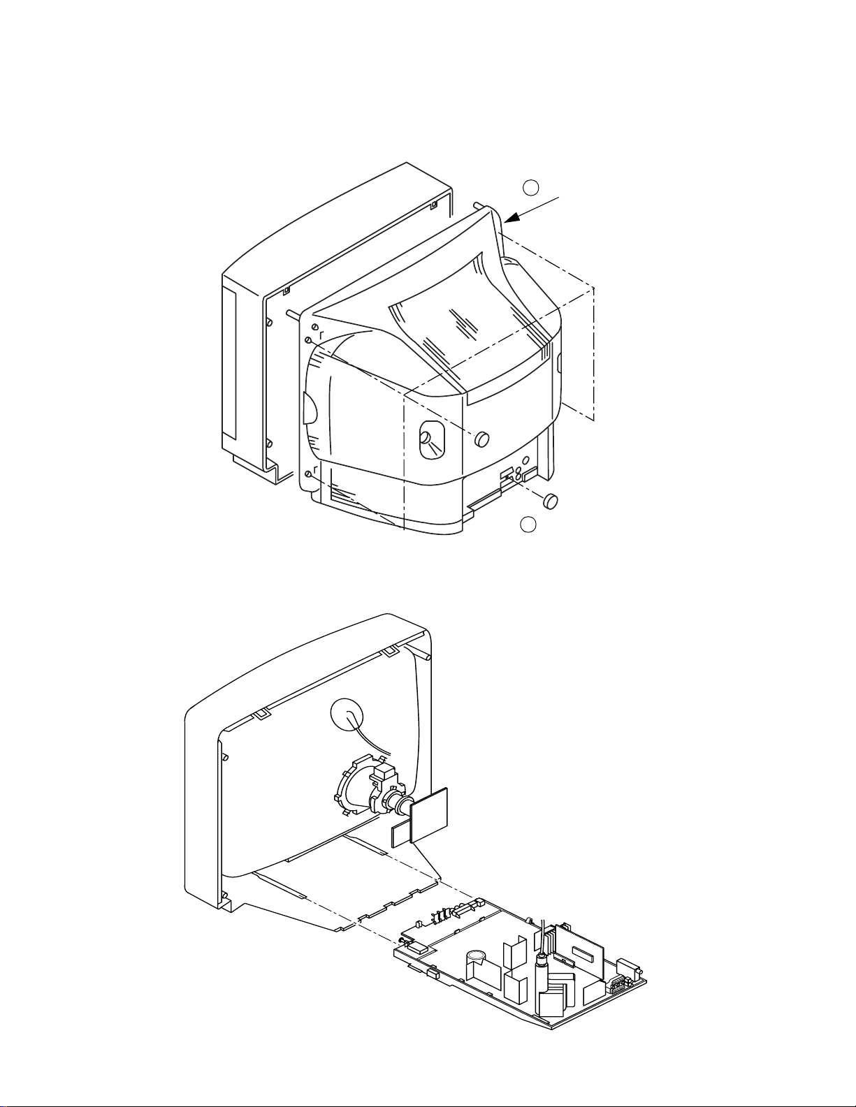
2-1. REAR COVER REMOVAL
SECTION 2
DISASSEMBLY
2 Rear Cover
2-2. CHASSIS ASSY REMOVAL
1 5 Screws BTV 4x16
12

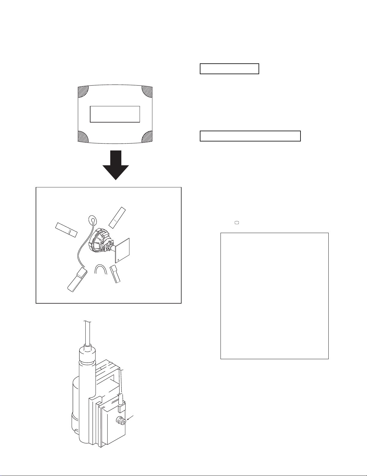
2-3. SERVICE POSITION
KV-29X5
2-4. H1 BOARD REMOVAL 2-5. S1 BOARD REMOVAL
Release the clip indicated.
To release, push the claws in the direction
of the arrow as indicated.
13
KV-29X5
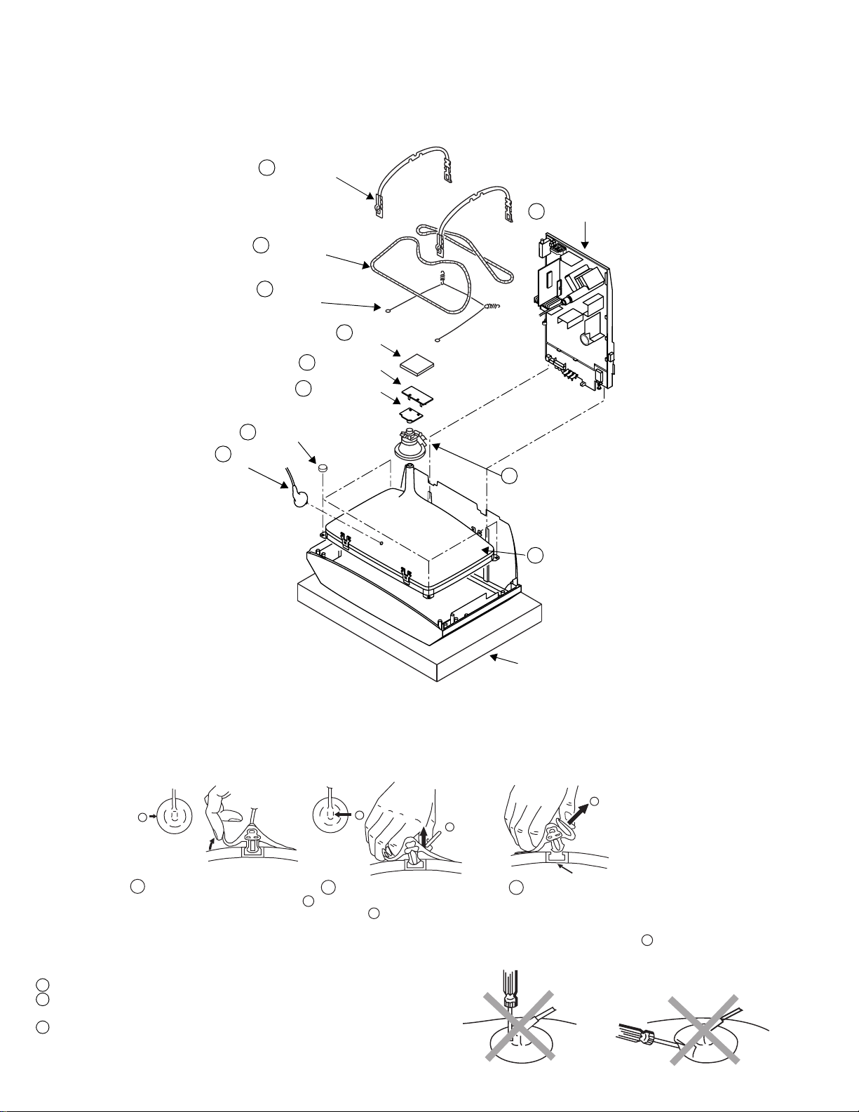
2-6. PICTURE TUBE REMOVAL
8 Degaussing coils
9 Spring Extension
7 Two DGC holders
2 Chassis assy
3 C board
4 VM Board
5 Neck assy
10 Four PT screws (M)
1 Anode cap
6 Deflection yolk
11 Picture tube
Cushion
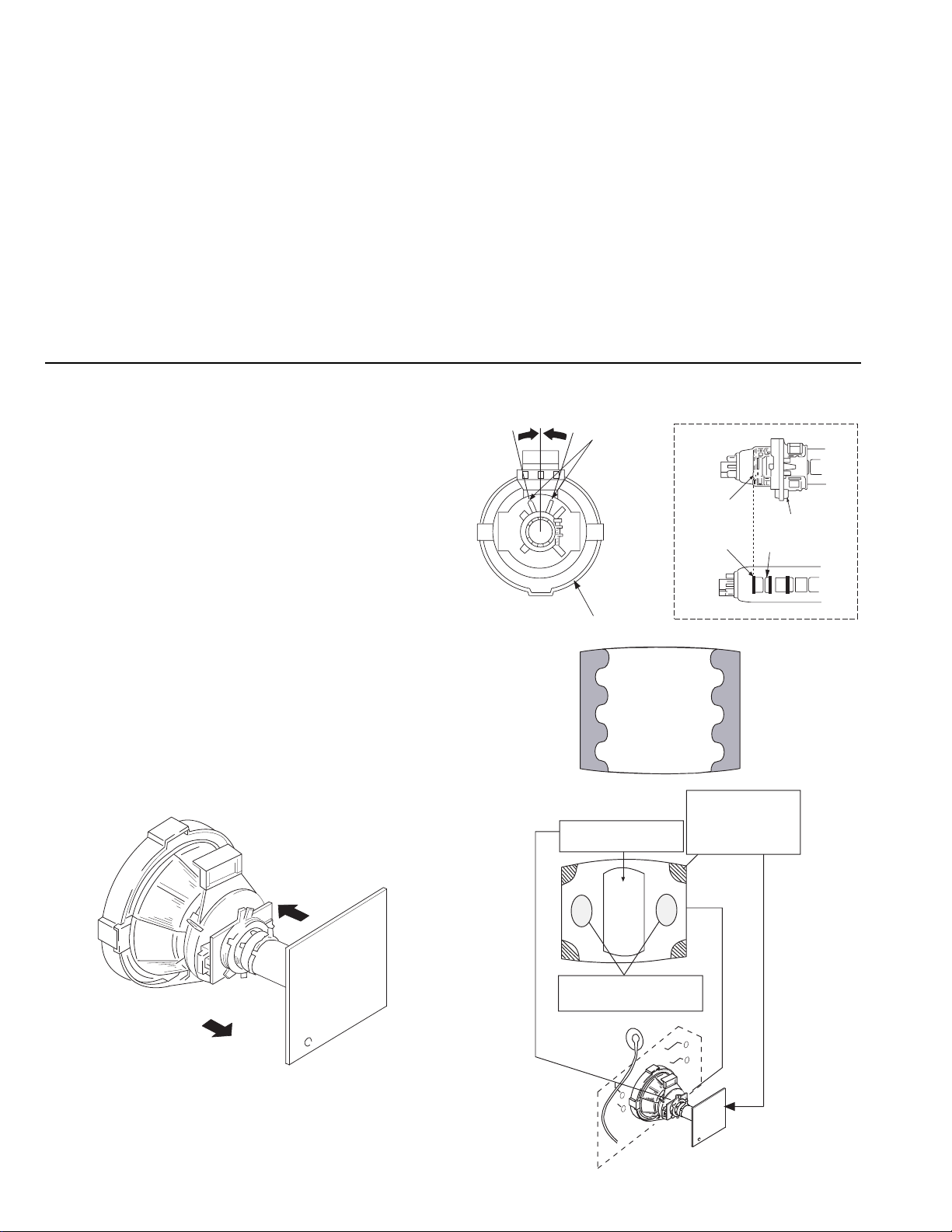
• REMOVAL OF ANODE-CAP
Note : Short circuit the a node of the picture tube and the anode cap to the metal chassis, CRT shield or carbo n pa int on the CRT, after removing the an ode.
* REMOVING PROCEDURES.
c
a
b
b
1
Turn up one side of the rubber cap in
the direction indicated by the arrow a
2 Using a thumb pull up the rubber cap
firmly in the direction indicated by the
arrow b
• HOW TO HANDLE THE ANODE-CAP
1 To preve nt damaging the surface of th e a node-cap do not use sharp materia ls.
2 Do not apply too great a pressure on the rubber, as this may cau s e damage to the
anode connector.
3 A metal fitting called a shatter hook terminal is fit ted inside the rubbe r ca p.
Do not turn the rubber foot over excessively this may cause damage if the shatter
hook sticks out.
14
3 When one side of the rubber cap is
Anode button
separated from the anode button, the
anode-cap can be removed by turning
up the rubber cap and pulling it up in
the direction of the arrow c
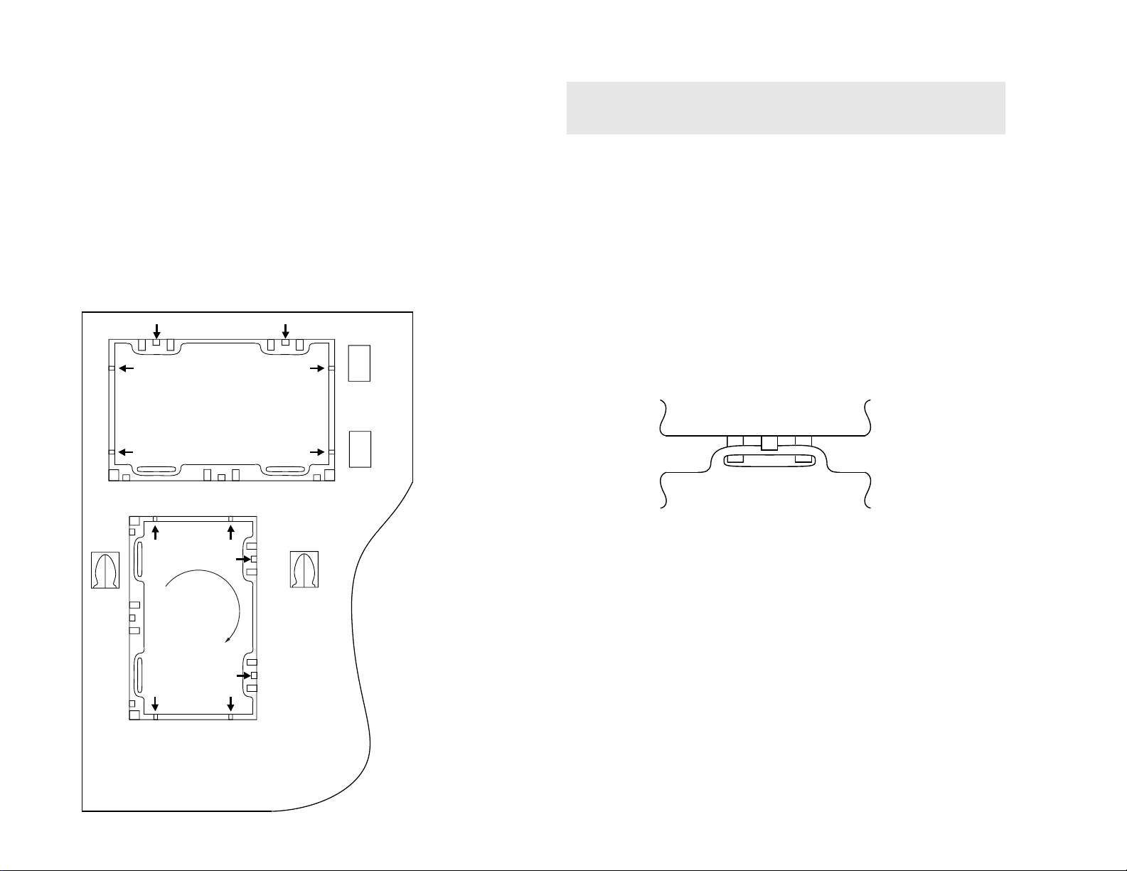
REMOVAL AND REPLACEMENT OF THE MAIN-BRACKET
BOTTOM PLATES.
For safety reasons, on no account should the plates be
£
removed and not refitted after servicing.
(1) REMOVING THE PLATES
In the event of servicing being required to the solder side of t he A Board printed
wiring board, the bottom plates fitted to the main chassis bracket require to be
removed.
This is performed by cutting the gates with a sharp wire cutter at the locations
shown and indicated by arrows.
Note :There are 2 plates fitted to the main bracket and secured by 4 gates.
Only remove the necessary plat e to gain access to the printed wiring board.
CatchCatch
15
Gate
Gate
Tab
Tab
GateGate
Catch
Tab
Gate
Gate
(2) REFITTING THE PLATES
Because the plates differ in size it is important that the correct plate s are ref itted i n
their original location.
Please note that the plates need to be rotated 180 degrees from th e cut position to
to allow the tabs to be fitted in the catch positions.
Catch
Tab
Refitting
Tab
Gate Gate
Catch
KV-29X5
KV-29X5
SECTION 3
SET-UP ADJUSTMENTS
• When com pl ete readjustment is necessary or a new
picture tube is installed, carry out the following
adjustments.
• Unless there are sp eci fic instructions to the contrary,
carry out these adjustments with the rated power supply.
• Unless there are sp eci fic instructions to the contrary, set the
controls and switches to the following settings :
Contrast ............... 80% [or remote control normal]
Brightness ............... 50%
Preparation:
1. In order to reduce the influence of geomagnetism on the set’s
picture tube, face it in an easterly or westerly direction.
2. Switch on the TV set’s power and degauss with the
degausser.
3-1. BEAM LANDING
1. Input an all-white signal from the pattern generator.
Set the Contrast and Brightness to normal.
2. Set the pattern generator raster signal to all Red.
3. Move the deflection yolk forward and adjust with the purity
control so that the Red is at the centre and the Blue and Green
take up equally sized areas on each side of the screen.
[See Fig.3-1 - 3-3].
4. Move the deflection yolk forward and adjust so that the entire
screen becomes Red. [See Fig.3-1].
5. Switch the raster si gnal to Blue, then to Green and verify the
purity condition.
6. When the position of the deflection yolk has been determined,
fasten the deflection yolk with the screws.
7. If the beam does not land correctly i n al l the corners, use
magnets to correct it. [See Fig.3-4].
Carry out the following adjustments in this order :
3-1. Beam Landing
3-2. Convergence
3-3. Focus
3-4. White balance
Note : Test equipment requ ired
1. Color bar/pattern generator.
2. Degausser.
3. Oscilloscope.
4. Digital multimeter.
5. DC Power supply.
Fig. 3-2
For 29" models align the neck assy
as indicated below.
Purity Control
A buckle
G1
G2
Deflection Y oke
GREEN
RED
BLUE
Fig. 3-3
Purity control corrects
this area.
Disk magnets or
rotatable disk
magnets correct
these areas (a - d).
Neck Assy
Fig. 3-1
16
ab
c
Deflection yolk positioning
corrects these areas.
d
a
c
b
d
Fig. 3-4
KV-29X5
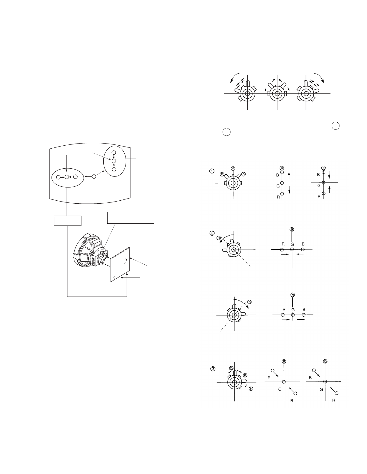
3-2. CONVERGENCE
Preparation:
• Before start ing this adjustment, adjust the focus, horizontal
size and vertical size.
• Minimize the Brightness setting.
• Input a dot pattern from the pattern generator.
(1) Horizontal and vertical static convergence
Centre dot
R
G
H.STAT
B
R
G
B
V.STAT Magnet
• Tilt the V.STAT magnet an d adjust the static convergence
by opening or closing the V.STAT magnet.
4. If the V.STAT magnet is moved in the direction of the a
and b arrows, the Red, Green and Blue points move as
indicated below.
C Board
RV701
SCREEN
RV702
1. [Moving horizontally], adjust the H.STAT control so that the
Red, Green and Blue points are on top of each other at the
centre of the screen.
2. [Moving vertically], adjust the V.STAT magnet so that the
Red, Green and Blue points are on top of each other at the
centre of the screen.
3. If the H.STAT variable resistor is unable to bring the Red,
Green and Blue points together at the centre of the screen,
adjust the horizontal convergence with the H.STAT variable
resistor and the V.STA T magnet in the manner indicated below.
[In this case, the H.STAT variable resistor and the V.STAT
magnet influence each other].
17
KV-29X5
RG B R G B R GB
RGBR
G
B
R
G
B
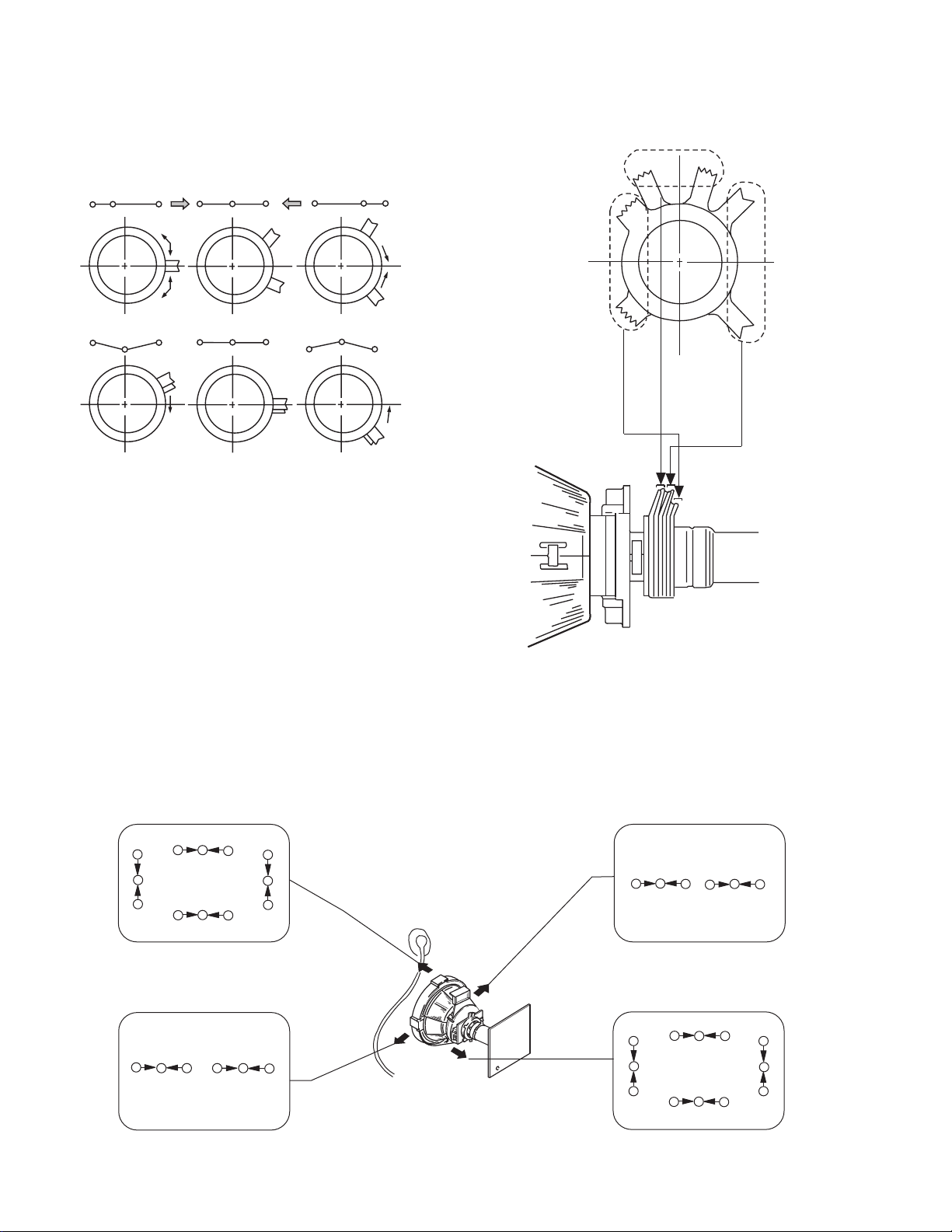
(2) Operation of the BMC (Hexapole) magnet.
• The respective dot position resulting from moving each
magnet interact, so be sure to perform adjustment whilst
tracking.
Use the H.STAT VR to adjust the Red, Green and Blue dots
so that they coincide at the centre of the screen
[by moving the dots in the horizontal direction].
V.STAT
Purity
BMC (Hexapole)
(3) Dynamic convergence adjustment.
Preparation:
• Before star ting this adjustment, adjust the horizontal and
vertical static convergence.
1. Slightly loosen the deflection yolk screws.
R
B
G
B
RG B
G
RG
B
R
B
G
B
G
R
R
2. Remove the deflection yolk spacer.
3. Move the deflection yolk as indicated in th e figure below and
optimize the convergence.
4. Tighten the deflection yolk screws.
5. Re-install the deflection yolk spacer.
G
B
B
G
R
R
RG
RG
B
B
RG
B
R
G
B
18
KV-29X5
c
a
d
b
Fit the permalloy assembly to the rear
of the CRT to correct the area at fault.
Permalloy
(4) Screen corner convergence.
• If you are unable to adjust the corner convergence properly,
this can be corrected by the use of permalloy assemblies.
a
a-d: screen-corner
convergence defect
c
b
d
3-3. Screen [G2], White balance
G2 Setting
1. Input a dot signal from the pattern generator.
2. Set the Picture, Brightness an d Colour to minimum.
3. Apply 170Vd c f rom an exte r n a l pow e r supply to the
R, G and B cathodes of the CRT.
4. Whilst watching the picture, adjust the G2 control [RV701
SCREEN] located on the C Board to the point just before the
flyback return lines disappear.
White balance adjustment
1. Input a ‘PAL’ all-white signal from the pattern generator.
2. Enter into the Service Mode.
3. Enter into the ‘Picture’ service menu.
4. Select the ‘Green drive’ and adjust so that the White Balance
becomes optimum.
5. Select the ‘Blue drive’ and adjust so that the White Balance
becomes optimum.
6. Set the Picture to MIN.
7. Set the ‘R-cut-off’ to 07.
8. Adjust the ‘G-cut-off’, and the ‘B-cut-off’ so that the White
Balance becomes optimum.
10. Press the button to return to TV operation.
FOCUS
PICTURE
R - Drive Adj
G - Drive Adj
B - Drive Adj
R - cut - off Adj
G - cut - off Adj
B - cut - off Adj
ID - start 02
ID - stop 01
ID - level 01
Bellfo Adj
Sub Colour Adj
Sub Brightness Adj
3-4.FOCUS
1. Input a Phillips colour pattern
2. Set the picture settings to normal.
3. Adjust the focus control located on the Flyback transformer to
bring the centre of the screen in to focus.
Note :Bring only the centre area of the screen into focus, switch to an
all-white pattern and confirm that the magenta ring is hardly
noticed. To obtain optimum focus balance the focus setting
between optimum scre en centre focus and a reduced magenta
ring level.
19
 Loading...