

Sony KV-29RS25, KV-27S25, KV-29RS25C, KV-29V35C, KV-29V65M Operating Instructions Manual
...
Trin 'tron Color TV
Operating Instructions
KV-27S25
KV-27S35
KV-2 7V2 5
KV-2 7V35
KV-29RS25
KV-29RS25C
KV-29V35C
KV-29V65M
KV-29V75M
KV-32S25 ..
KV-32S35 !
KV-32TW25
KV-32V25
KV-32V35
KV-34V35C
KV-35V35
KV-35V45
KV-35V75
©1996 by Sony Corporation
To prevent fire or shock hazard, do not
expose the television to rain or
moisture.
RISK OF ELECTRIC SHOCK
DO NOT OPEN
ATTENTION
RISQUE DE CHOC ELECTRIQUE,
NE PAS OUVRIR
PRECAUCION
RIESGO DE CHOQUE ELECTRICO
NO ABRIR
CAUTION : TO REDUCE THE RISK OF ELECTRIC SHOCK,
.... DO NOT REMOVE COVER (OR BACK).
NO USER-SERVICEABLE PARTS INSIDE.
REFER SERVICING TO QUALIFIED SERVICE PERSONNEL.
This symbol is intended to alert the user to the
presence of uninsulated "dangerous voltage"
within the product's enclosure that may be of
sufficient magnitude to constitute a risk of
electric shock to persons.
This symbol is intended to alert the user to the
presence of important operating and
maintenance (servicing) instructions in the
literature accompanying the appliance.
CAUTION
To prevent electric shock, do not use this polarized AC plug with
an extension cord, receptacle or other outlet unless the blades can
be fully inserted to prevent blade exposure.
Pi;ecautions
Safety --
• Operate the TV only on 120 V AC (except KV-29RS25C/
29V35C/34V35C).
• Operate the TV only on 220 V AC (KV-29RS25C/29V35C/
34V35C only).
• One blade of the plug is wider than the other for safety
purposes and will fit into the power outlet only one way. If
you are unable to insert the plug fully into the outlet,'contact
your dealer (except KV-29RS25C/29V35C/34V35C).
• Should any liquid or solid object fall into the cabinet, unplug
the TV and have it checked by qualified personnel before
_._perati_g it any further.
2
I
• Unplug the TV from the wall outlet if you are not going to
use it for several days or more. To disconnect the cord, pull it
out by the plug. Never pull the cord itself.
For details concerning safety precautions, see the supplied leaflet
"IMPORTANT SAFEGUARDS."
Installing
• To prevent internal heat build-up, do not block the
ventilation openings.
• Do not install the TV in a hot or humid place, or in a place
subject to excessive dust or mechanical vibration.
CAUTION
When using TV games, computers, and similar products with
your TV, keep the brightness and contrast functions at low
settings. If a fixed (non-moving) pattern is left on the screen for
long periods of time at a high brightness or contrast setting, the
image can be permanently imprinted onto the screen. These
types of imprints are not covered by your warranty because they
are the result of misuse.
NOTIFICATION
This equipment has been tested and found to comply with the
limits for a Class B digital device pursuant to Part 15 of the FCC
Rules. These limits are designed to provide reasonable protection
against harmful interference in a residential installation. This
equipment generates, uses, and can radiate radio frequency
energy and, if not installed and used in accordance with the
instructions, may cause harmful interference with radio
communications. However, there is no guarantee that
interference will not occur in a particular installation. If this
equipment does cause harmful interference to radio or television
reception, which can be determined by turning the equipment off
and on, the user is encouraged to try to correct the interference
by one or more of the following measures:
- Reorient or relocate the receiving antennas.
- Increase the separation between the equipment and receiver.
- Connect the equipment into an outlet on a circuit different
from that to which the receiver is connected.
- Consult the dealer or an experienced radio/TV technician for
help.
You are cautioned that any changes or modifications not
expressly approved in this manual could void your
authority to operate this equipment.
This document is for the remote commander RM-Y136/Y137.
MODEL: KV-27S25 / 27S35 / 27V25/ 27V35 / 29RS25 / 29RS25C /
29V35C / 29V65M / 29V75M / 32S25 / 32S35/ 32TW 25/
32V25/32V35/34V35C/35V35/35V45/35V75
Please keep this notice with the instruction manual.
Note on Caption Vision
This television receiver provides display of television dosed
captioning in accordance with § 15.119 of the FCC rules.
Note to CAW system installer
This reminder is provided to call the CATV system installer's
attention to Article 820-40 of the NEC that provides guidelines for
proper grounding and, in particular, specifies that the cable
ground shall be connected to the grounding system of the
building, as close to the point of cable entry as practical.
Use of this television receiver for other than private viewing of
programs broadcast on UHF or VHF or transmitted by cable
companies for the use of the general public may require
authorization from the broadcaster, cable company and/or
program owner.
Owner's Record
The model and serial numbers are located at the rear of the TV.
Record these numbers in the spaces provided below. Refer to
them whenever you c-_ll upon your Sony dealer regarding this
product.
Model No.
Serial No.
4 Welcome!
4 Checking your model number
Getting Started
5 Step 1: Hookup
12 Step 2: Installing the glass door and adjusting the
shelf
14 Step 3: Setting up the remote commander
15 Step 4: Setting up the TV automatically
(^uTo SETUP)
18 Changing the menu language
18 Adjusting the tilt of the picture (TILTCORRECTION)
Operations
19 Watching the TV
21 Watching two programs at a time--PIP
22 Adjusting the picture (VIDEO)
23 Selecting the video mode (VIDEO)
24 Adjusting picture brightness automatically
(LIGHTSENSOR)
24 Adjusting the sound (AUDIO)
25 Using audio effect (EFFECT)
26 Selecting stereo or bilingual programs (MTS)
27 Setting the speaker switch (SPEAKER)
27 Setting audio out (AUDIOOUT)
28 Setting daylight saving time (DAYLIGHTSAVING)
28 Setting the clock (CURRENTTIMESET)
29 Setting the timer to turn the TV on and off (ON/OFF
TIMER)
30 Customizing the channel names (CHANNELCAP'nON)
31 Blocking out a channel (CHANNELBLOCK)
31 Setting your favorite channels (FAVORITECHANNEL)
32 Setting video labels (VIDEOLABEL)
33 Setting Caption Vision (CAPTIONVISION)
34 Operating video equipment
36 Operating a cable box or DBS receiver
Additional Information
37 Troubleshooting
38 Specifications
Back cover Index
The captions in parentheses indicate menu names.
~
3
Thank you for purchasing the Sony Trinitron ® Color
TV. Here are some of the fea_res you will enjoy with
your TV:
On-screen menus that let you set the picture quality,
sound, and other settings.
• Picture-in-Picture (PIP) that allows you to watch
another TV channel, video or cable image as a
window picture.
• Surround system that simulates the sound quality of
a concert hall or movie theater (KV-27S25/27S35/
29RS25/29RS25C/32S25/32S35/32TW25 only).
• SRS (SOUND RETRIEVAL SYSTEM) that allows
you to receive realistic sound that recaptures audio
"clues" originally present but masked in the
__rec0rd!ng process so that the action seems to
happen all around you (KV-27V25/27V35/29V35C/
29V65M/29V75M/32 V25/32V35/34V35C/35V35/
35V45/35V75 only).
• LightSensor TMthat automatically adjusts the
brightness of the picture (KV-27V25/27V35/29V35C/
29V65M/29V75M/32 V25/32 V35/34V35C/35V35/
35V45/35V75 only).
• S-Link T_ that allows you to automatically change
the TV's input mode, turn on the VCR, and play a
tape by just pressing the VCR's play button
(KV-27V25[27V35/29V35C[29V65M[29V75M/32 V25/
32V35/34V35C/35V35/35V45/35V75 only). This
feature is originally designed by Sony.
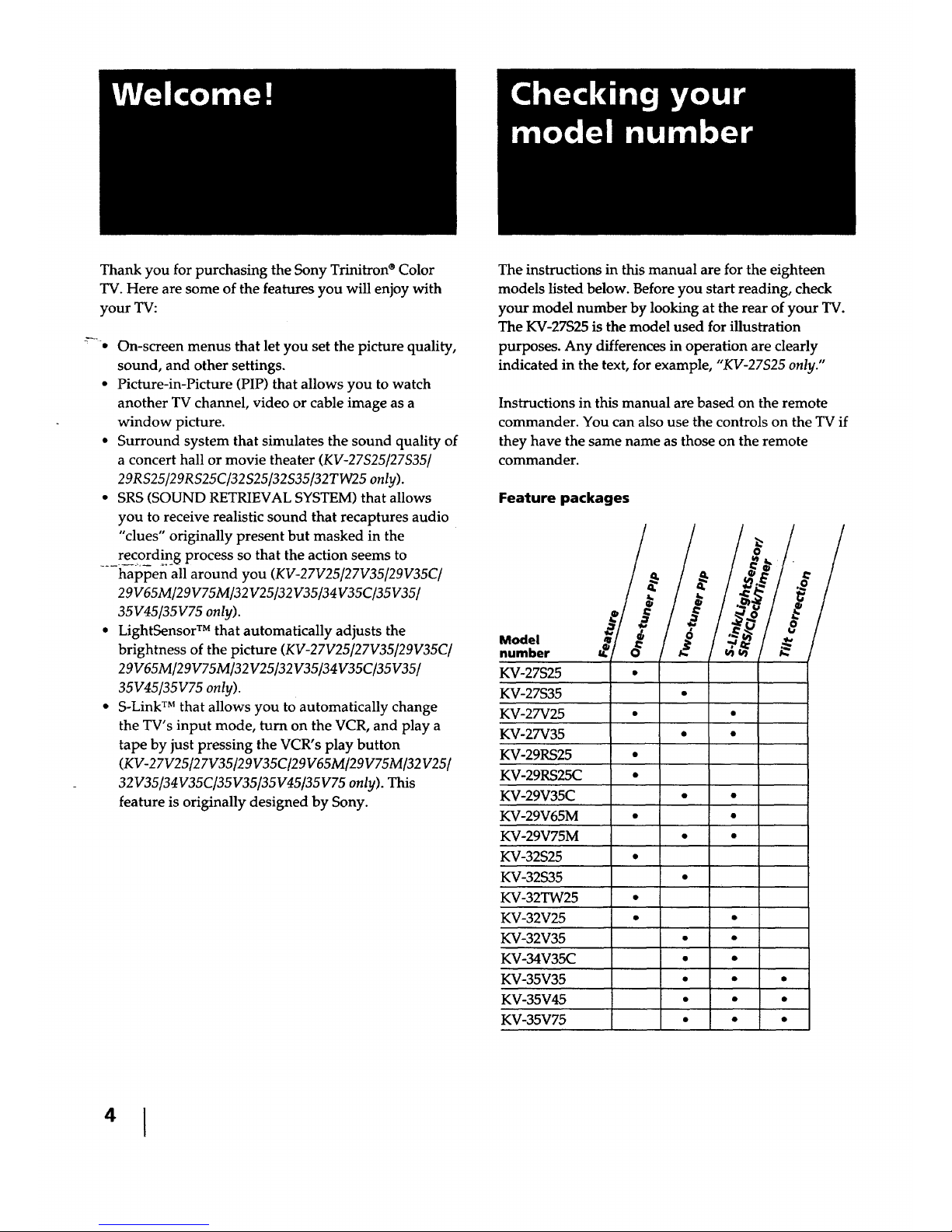
The instructions in this manual are for the eighteen
models listed below. Before you start reading, check
your model number by looking at the rear of your TV.
The KV-27S25 is the model used for illustration
purposes. Any differences in operation are clearly
indicated in the text, for example, "KV-27S25 only."
Instructions in this manual are based on the remote
commander. You can also use the controls on the TV if
they have the same name as those on the remote
commander.
Feature packages
Model
number
KV-27S25 •
KV-27S35
KV-27V25 • •
KV-27V35 • •
KV-29RS25 •
KV-29RS25C
KV-29V35C • •
KV-29V65M • •
KV-29V75M • •
KV-32S25 •
KV-32S35 •
KV-32TW25 •
KV-32V25 • •
KV-32V35 • •
KV-34V35C " "
KV-35V35 • • •
KV-35V45 • • "
KV-35V75 • " "
Getting Started
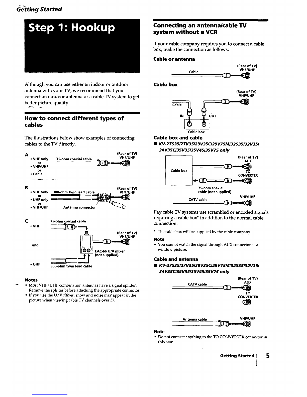
Although you can use either an indoor or outdoor
antenna with your TV, we recommend that you
connect an outdoor antenna or a cable TV system to get
better picture quality.
How to connect different types of
cables
The illustrations below show examples of connecting
cables to the TV directly.
A
• VHF only
or
• VHF/UHF
or
• Cable
75-ohm coaxial cable
(Rear of TV)
VHF/UHF
B
• VHF only
or
• UHF only
or
• VHF/UHF
(Rear of TV)
300-ohm twin lead cable _ VHFIUHF
i .... ctor__
Antenna conne
C
• VHF
and
• UHF
75-ohm coaxial cable
_EAC-66 U/ (Rear of TV)
V mixer
tI (not supplied)
/
300-ohm twin lead cable
Notes
• Most VHF/UHF combination antennas have a signal splitter.
Remove the splitter before attaching the appropriate connector.
• If you use the U/V r_ixer, snow and noise may appear in the
picture when viewing cable TV channels over 37.
IIIIIII
Connecting an antenna/cable TV
system without a VCR
Ifyour cable company requires you to connect a cable
box, make the connection as follows:
Cable or antenna
Cable
Cable
IN
Cable box
(Rear of TV)
VHFIUHF
(Rear of W)
VHF/UHF
I
Cable box
Cable box and cable
• KV-27S35127V35129V35CI29V75MI32S35132V351
34V35C/35V35/35V45135V75 only
(Rear of TV)
AUX
Cable box TO
CONVERTER
75-ohm coaxial
cable (not supplied)
VHF/UHF
CATV cable _ml _
Pay cable TV systems use scrambled or encoded signals
requiring a cable box* in addition to the normal cable
connection.
* The cable box will be supplied by the cable company.
Note
• You cannot watch the signal through AUX connector as a
window picture.
Cable and antenna
[] KV.27S35127V35/29V35CI29V75MI32S35/32V351
34V35C/35V35/35V45135V75 only
(Rear of TV)
AUX
CAW cable _,m_
TO
CONVERTER
Antenna cable
vHF/UHF
Note
• Do not connect anything to the TO CONVERTER connector in
this case.
Getting Started [
5
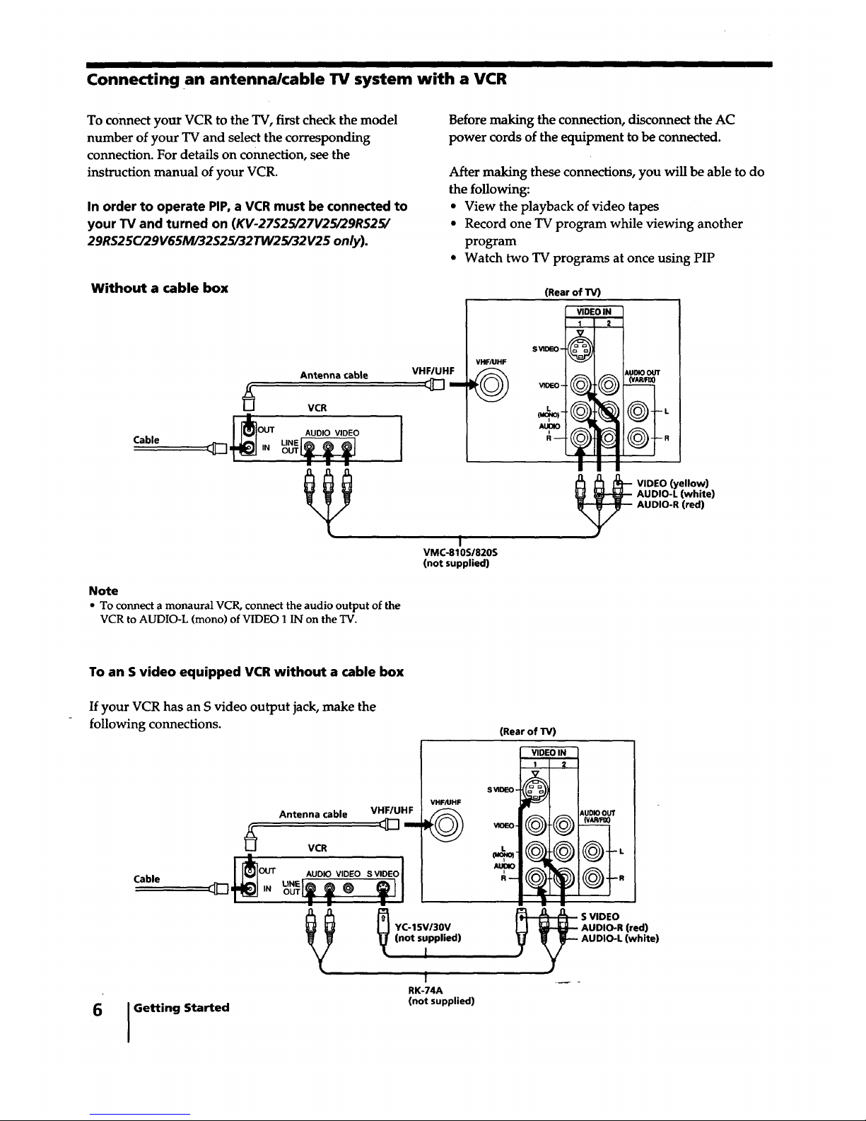
Connecting an antenna/cable TV system with a VCR
To connect your VCR to the TV, first check the model
number of your TV and seleCt the corresponding
connection. For details on connection, see the
instruction manual of your VCR.
In order to operate PIP, a VCR must be connected to
your TV and turned on (KV-27S25/27V25/29RS25/
29RS25C/29V65M/32S25/32TW25/32 V25 only).
Before making the connection, disconnect the AC
power cords of the equipment to be connected.
After making these connections, you will be able to do
the following:
• View the playback of video tapes
• Record one TV program while viewing another
program
• Watch two TV programs at once using PIP
Without a cable box
Antenna cable
VCR
J _']OUT AUDIO VIDEO
Cable _rN ___
VHF/UHF
VHF/UHF_m _
I
VMC-810S/820S
(not supplied)
(Rear of TV)
VIDEO IN
1 2
SVlDEO-
A_
_UDIO OUT
---L
VIDEO (yellow)
AUDIO-L (white)
AUDIO-R (red)
Note
• To connect a monaural VCR, connect the audio output of the
VCR to AUDIO-L (mono) of VIDEO 1 IN on the TV.
To an S video equipped VCR without a cable box
If your VCR has an S video output jack, make the
following connections.
(RearofTV)
Antenna cable
Cable
VHF/UHF
m
VCR
OUT AUDIO VIDEO S VIDEO ]
= m =
Q
Getting Started
VHF/UHF
©
YC-15V/30V
(not supplied)
!
1
RK-74A
(not supplied)
VIDEO IN
1 2
SVlDEO- _
AUD_ OUT
-- AUDIO-L (white)
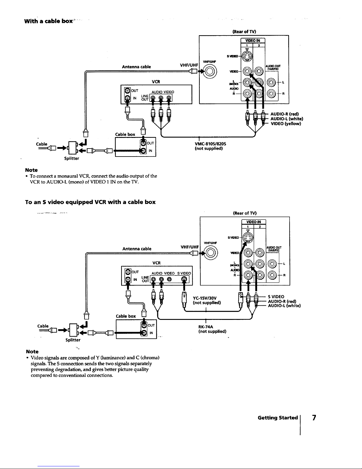
With a cable box '_..........
Antenna cable
VCR
I _-_OUT AUDIO VIDEO
Splitter
Note
• To connect a monaural VCR, connect the audio output of the
VCR to AUDIO-L (mono) of VIDEO 1 IN on the TV.
VHF/UHF
I
(Rear of TV)
VHF/UHF
©
VIDEO IN
1 2
S_DEO- @
AUOIOOUT
(Vk'_F00
R
1
VMC-810SI820S
(notsupplied)
AUDIO-R (red)
AUDIO-L (white)
VIDEO (yellow)
To an S video equipped VCR with a cable box
(Rear of TV)
Antenna cable
•T-_'IJ*'_=_ o
Splitter
VCR
OINUT AUDIO VIOEO SVIDEO1
VHF/UHF
YC-15VI30V
(not supplied)
i
I
RK-74A
(not supplied)
SVlDEO-
VIDEG
L
AUDIO
i
R-
Note
• Video signals are composed of Y (luminance) and C (chroma)
signals. The S connection sends the two signals separately
preventing degradation, and gives better picture quality
compared to conventional connections.
VIDEO IN
_ AUDIOOUT
_@@--"
@
__ S VIDEO
AUDIO-R (red)
AUDIO-L (white)
Getting Started 7
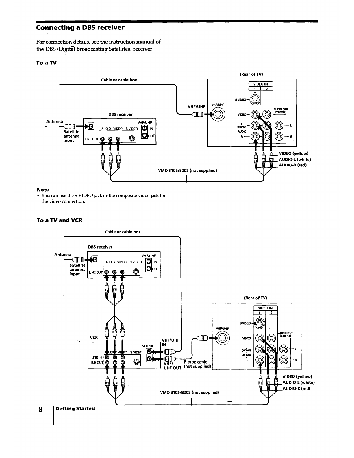
Connecting a DBS receiver
For connection details, see the instruction manual of
the DBS (Digit_ Broadcasting Satellites) receiver.
Toa TV
Cable or cable box
DBS receiver
Antenna VHF/UHF I
-- AUDIO VIDEO SVIDEO _-_ IN I
I
(Rear of TV)
VIDEO IN
I 2
SvIoc-o- O
VMC-810S/820S (not supplied)
1
(v_
Note
• You can use the S VIDEO jack or the composite video jack for
the video connection.
VIDEO (yellow)
AUDIO-L (white)
AUDIO-R (red)
To a TV and VCR
Cable or cable box
Antenna
Satellite
antenna
input
_o
(Rear of TV)
VHF/UHF
©
VIDEO IN
1 2
SVIDEO-
,_o
AUDIO OUT
(VAP,_X)
VMC-810S/820S (not supplied)
VIDEO (yellow)
AUDIO-L (white)
AUDIO-R (red)
8 I Getting Started
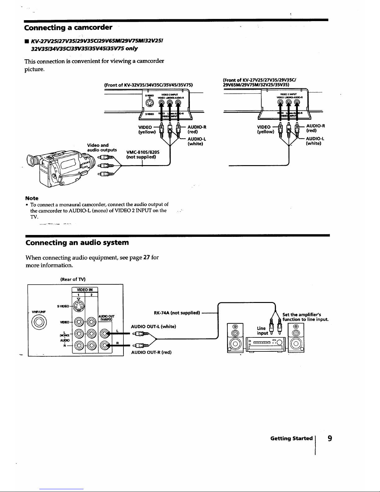
Connecting a camcorder
• KV-27V25127V35129V35CI29V65MI29V75MI32V251
32V3$I34V35CI3SY35135V45135VT$ only
This connection is convenient for viewing a camcorder
picture.
(Front of KV-32V35134V35C/35V45135V75)
(Front of KV-27V25127V35/29V35C/
29V65MI29V75MI32V25135V35)
Video and
audio outputs
VIDEO
(yellow) _
VMC-810S/820S
(not supplied)
I
Note
• To connect a monaural camcorder, connect the audio output of
the camcorder to AUDIO-L (mono) of VIDEO 2 INPUT on the
TV.
AUDIO-R
(red)
AUDIO-L
(white)
Connecting an audio system
When connecting audio equipment, see page 27 for
more information.
(Rear of TV)
8VIDEO-
VIDEO-
VIDEO IN
1 2
kU_ OUT
@.Q M
RK-74A (not supplied)
AUDIO OUT-L (white)
AUDIO OUT-R (red)
/_ Set the amplifier's
A Afunction to line input.
Line H _
inp.t_ _ I_--_1
Getting Started I 9
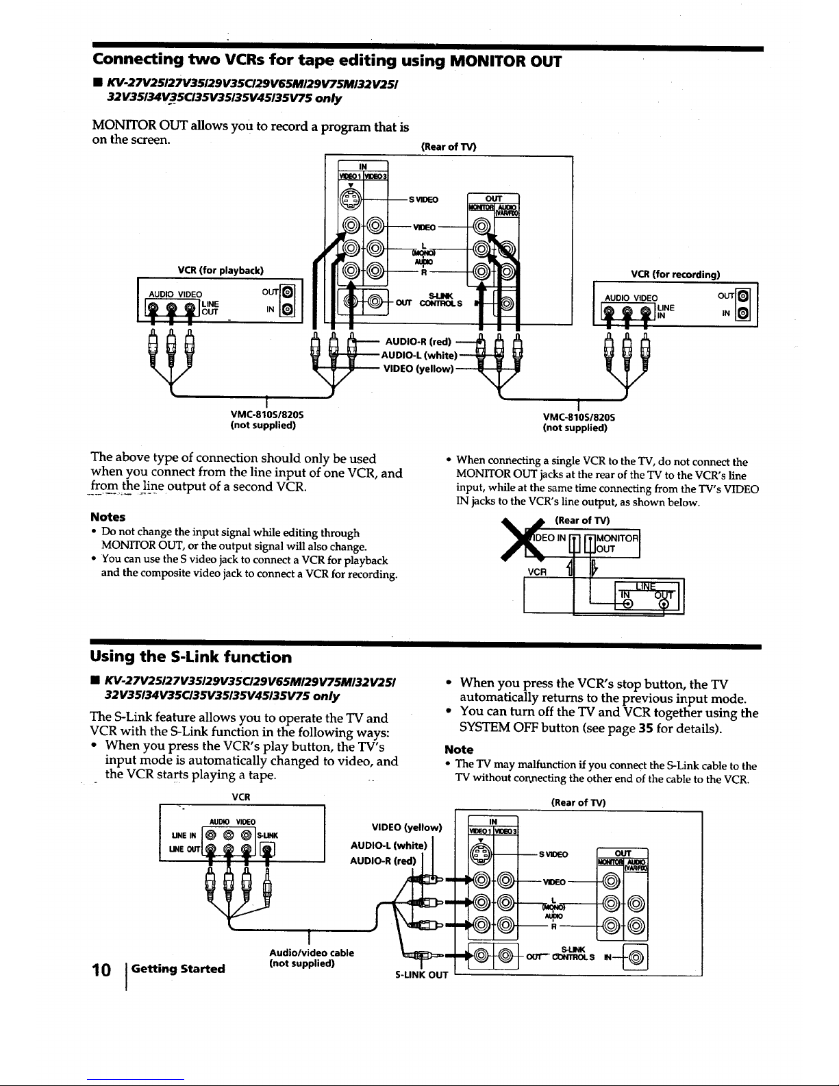
Connecting two VCRs for tape editing using MONITOR OUT
• KV.27V25127V35129V35CI29V65MI29V75MI32V251
32V35134V35CI35V35135V45135V75 only
MONITOR OUT allowsyou torecordaprogram thatis
on the screen. (Rear of TV)
VCR (for playback)
I AUDIO VIDEO
I
VMC-810S/820S
(not supplied)
-- -- SVIDEO
OUT CONTROLS
OUT
AUDIO-L (white)_ V
VIDEO (yellow) ,_
VCR(for recording)
AUDIO VIDEO
[ ,UNE iN
_ m m
I
VMC-810S1820S
(not supplied)
The above type of connection should only be used
when you connect from the line input of one VCR, and
from the line output of a second VCR.
Notes
• Do not change the input signal while editing through
MONITOR OUT, or the output signal will also change.
• You can use the S video jack to connect a VCR for playback
and the composite video jack to connect a VCR for recording.
• When connecting a single VCR to the TV, do not connect the
MONITOR OUT jacks at the rear of the TV to the VCR's line
input, while at the same time connecting from the TV's VIDEO
IN jacks to the VCR's line output, as shown below.
X (Rear of TV)
EO,NITl ITIMONITORI
OUT I
VCR L_ L_ LINE
Using the S-Link function
• KV-27V25127V35129V35C/29V65M129V75M/32V251
32V35/34V3$CI35V35135V45/35V75 only
The S-Link feature allows you to operate the TV and
VCR with the S-Link function in the following ways:
• When you press the VCR's play button, the TV's
input mode is automatically changed to video, and
the VCR starts playing a tape. ..
VCR
• When you press the VCR's stop button, the TV
automatically returns to the previous input mode.
• You can turn off the TV and VCR together using the
SYSTEM OFF button (see page 35 for details).
Note
• The TV may malfunctionifyou connect theS-Link cableto the
TV without cor_nectingthe otherend of thecable to theVCR.
(Rear of TV)
10 {Getting
AUDIO VIDEO
@@@s._
Started
VIDEO (yellow)
AUDIO-L (white)
!
Audiolvideo cable _3]:) I
(not supplied)
S-LINK OUT
IN
_DEO1' VIDEO_
m B SVIDEO
@.® ,--
@--
@@
@@
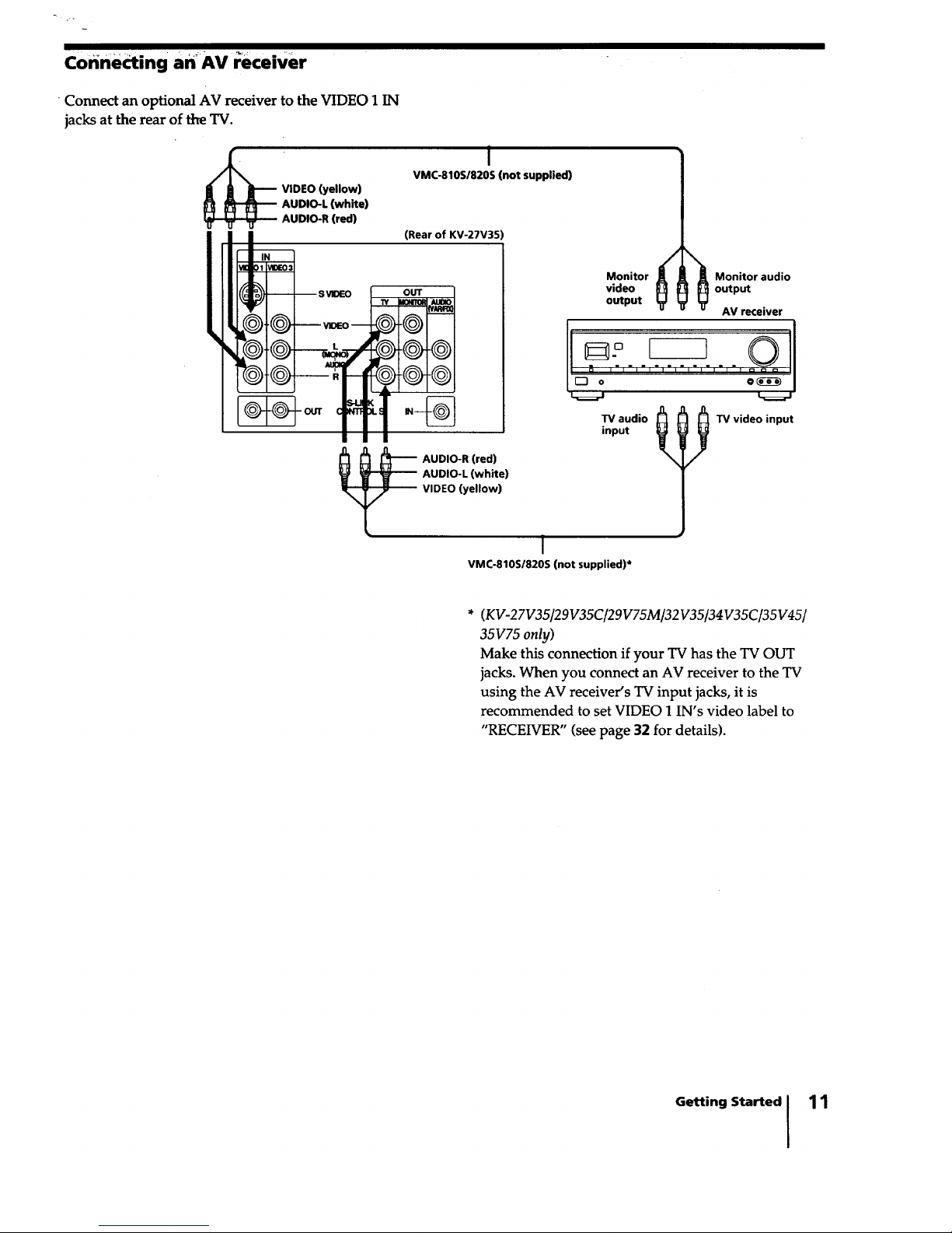
corinecting an_AV i;eceiver
• Connect an optional AV receiver to the VIDEO 1 IN
jacks at the rear of the TV.
VIDEO (yellow)
AUDIO-L (white)
AUDiO-R (red)
w
I
VMC-810S/820S (not suppiied)
(Rear of KV-27V35
OUT
m_
-@-@
-@-@
AUDIO-R (red)
AUDIO-L (white)
VIDEO (yellow)
I
VMC-810S/820S (not supplied)*
Monitor
video
output
? I I
TV audio
input
Monitor audio
output
AV receiver
TV video input
* (KV-27V35/29V35C/29V75M/32V35/34V35C/35V45/
35V75 only)
Make this connection if your TV has the TV OUT
jacks. When you connect an AV receiver to the TV
using the AV receiver's TV input jacks, it is
recommended to set VIDEO 1 IN's video label to
"RECEIVER" (see page 32 for details).
Getting Started I 11
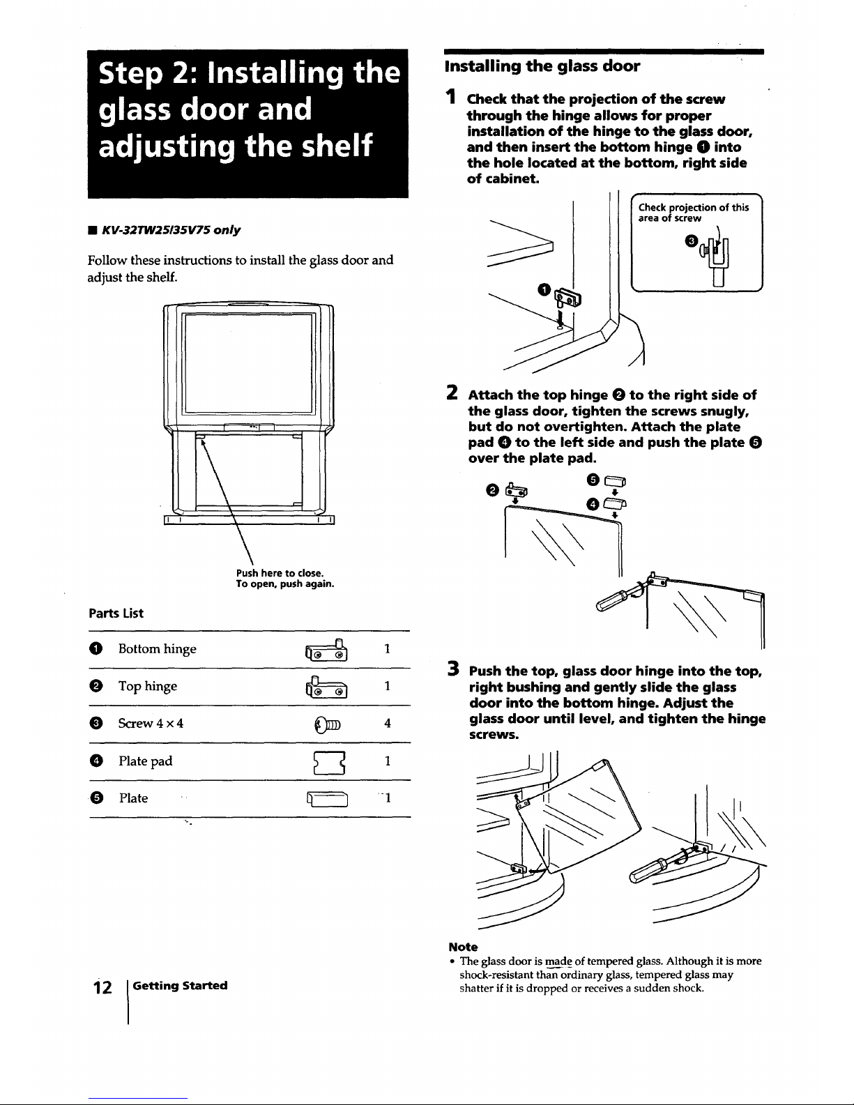
Installing the glass door
1
• KV-32TW25/35V75 only
Follow these instructions to install the glass door and
adjust the shelf.
Parts List
0
0
0
Check that the projection of the screw
through the hinge allows for proper
installation of the hinge to the glass door,
and then insert the bottom hinge O into
the hole located at the bottom, right side
of cabinet.
Check projection of this
area of screw
2 Attach the top hinge 0 to the right side of
the glass door, tighten the screws snugly0
but do not overtighten. Attach the plate
pad 0 to the left side and push the plate 0
over the plate pad.
Push here to close. II
__
To open. push again. __
IL
Bottom hinge [_ 1
3 Push the top, glass door hinge into the top,
Top hinge _ 1 right bushing and gently slide the glass
door into the bottom hinge. Adjust the
Screw 4 x 4 _ 4 glass door until level, and tighten the hinge
screws.
O Plate pad _-_ 1
0 Plate _ _1
12 Getting Started
Note
• The glass door is made of tempered glass. Although it is more
shock-resistant than ordinary glass, tempered glass may
shatter if it is dropped or receives a sudden shock.
 Loading...