

Sony kv 29sl40 Service Manual
KV-27S40 / 27S45 / 27S65 / 29SL40 / 29SL40A / 29SL40C/
29SL45 / 29SL65 / 29SL65C/ 29XL40M / 29XL40P / 29XT11A
SELF-DIAGNOSTIC FUNCTION
SERVICE MANUAL
MODEL COMMANDER DEST. CHASSIS NO.
KV-27S40
KV-27S40
KV-27S45
KV-27S45
KV-27S65
KV-27S65
KV-29SL40
KV-29SL40A
KV-29SL40C
KV-29SL45
KV-29SL65
RM-Y165 US SCC-S01H-A
RM-Y165 CND SCC-S03E-A
RM-Y167 US SCC-S01J-A
RM-Y167 CND SCC-S03F-A
RM-Y167 US SCC-S01K-A
RM-Y167 CND SCC-S03G-A
RM-Y165 E SCC-S04X-A
RM-Y165 E SCC-S04S-A
RM-Y165 E SCC-S04U-A
RM-Y167 E SCC-S04Y-A
RM-Y167 E SCC-S06F-A
BA-4
CHASSIS
KV-29SL65C
KV-29XL40M
KV-29XL40P
KV-29XT11A
RM-Y167 E SCC-S04V-A
RM-Y165 MX SCC-S02D-A
RM-Y165 E SCC-S04R-A
RM-Y165 E SCC-S04T-A
KV-27S45
RM-Y167
TRINITRON® COLOR TV
— 1 —
KV-27S40 / 27S45 / 27S65 / 29SL40 / 29SL40A / 29SL40C/
g
g
)
y
(
)
)
(
(
y (
)
y
(
(
)
)
y
)
29SL45 / 29SL65 / 29SL65C/ 29XL40M / 29XL40P / 29XT11A
WARNINGS AND CAUTIONS
CAUTION!
SHORT CIRCUIT THE ANODE OF THE PICTURE TUBE AND
THE ANODE CAP TO THE METAL CHASSIS, CRT SHIELD,
OR CARBON PAINTED ON THE CRT, AFTER REMOVING
THE ANODE.
WARNING!!
AN ISOLATION TRANSFORMER SHOULD BE USED
DURING ANY SERVICE TO AVOID POSSIBLE SHOCK
HAZARD, BECAUSE OF LIVE CHASSIS.THE CHASSIS OF
THIS RECEIVER IS DIRECTLY CONNECTED TO THE AC
POWER LINE.
SAFETY-RELATED COMPONENT WARNING!!
COMPONENTS IDENTIFIED BY SHADING AND MARK
¡ ON THE SCHEMATIC DIAGRAMS, EXPLODED VIEWS
AND IN THE PARTS LIST ARE CRITICAL FOR SAFE
OPERATION. REPLACE THESE COMPONENTS WITH
SONY PARTS WHOSE PART NUMBERS APPEAR AS
SHOWN IN THIS MANUAL OR IN SUPPLEMENTS
PUBLISHED BY SONY. CIRCUIT ADJUSTMENTS THAT
ARE CRITICAL FOR SAFE OPERA TION ARE IDENTIFIED
IN THIS MANUAL. FOLLOW THESE PROCEDURES
WHENEVER CRITICAL COMPONENTS ARE REPLACED
OR IMPROPER OPERATION IS SUSPECTED.
SELF-DIAGNOSTIC FUNCTION
ATTENTION
APRES AVOIR DECONNECTE LE CAP DE L'ANODE, COURT-CIRCUITER
L'ANODE DU TUBE CATHODIQUE ET CELUI DE L'ANODE DU CAP AU
CHASSIS METALLIQUE DE L'APPAREIL, OU AU COUCHE DE CARBONE
PEINTE SUR LE TUBE CATHODIQUE OU AU BLINDAGE DU TUBE
CATHODIQUE.
ATTENTION!!
AFIN D'EVITER TOUT RESQUE D'ELECTROCUTION PROVENANT D'UN
CHÁSSIS SOUS TENSION, UN TRANSFORMATEUR D'ISOLEMENT DOIT
ETRE UTILISÉ LORS DE TOUT DÉPANNAGE. LE CHÁSSIS DE CE
RÉCEPTEUR EST DIRECTEMENT RACCORDÉ À L'ALIMENTATION
SECTEUR.
ATTENTION AUX COMPOSANTS RELATIFS A LA SECURITE!!
LES COMPOSANTS IDENTIFIES PAR UNE TRAME ET PAR UNE MARQUE
¡ SUR LES SCHEMAS DE PRINCIPE, LES VUES EXPLOSEES ET LES
LISTES DE PIECES SONT D'UNEIMPORTANCE CRITIQUE POUR LA
SECURITE DU FONCTIONNEMENT . NE LES REMPLACER QUE PAR DES
COMPOSANTS SONY DONT LE NUMERO DE PIECE EST INDIQUE DANS
LE PRESENT MANUEL OU DANS DES SUPPLEMENTS PUBLIES PAR
SONY . LES REGLAGES DE CIRCUIT DONT L'IMPORT ANCE EST CRITIQUE
POUR LA SECURITE DU FONCTIONNEMENT SONT IDENTIFIES DANS
LE PRESENT MANUEL. SUIVRE CES PROCEDURES LORS DE CHAQUE
REMPLACEMENT DE COMPOSANTS CRITIQUES, OU LORSQU'UN
MAUVAIS FONTIONNEMENT SUSPECTE.
The units in this manual contain a self-diagnostic function. If an error occurs, the STANDBY/TIMER lamp will automatically begin to
flash. The number of times the lamp flashes translates to a probable source of the problem. A definition of the STANDBY/TIMER lamp
flash indicators is listed in the instruction manual for the user's knowledge and reference. If an error symptom cannot be reproduced, the
remote commander can be used to review the failure occurrence data stored in memory to reveal past problems and how often these
problems occur.
1. DIAGNOSTIC TEST INDICATORS
When an error occurs, the ST ANDBY/TIMER lamp will flash a set number of times to indicate the possible cause of the problem. I f there
is more than one error, the lamp will identify the first of the problem areas.
Results for all of the following diagnostic items are displayed on screen. No error has occured if the the screen displays a "0" .
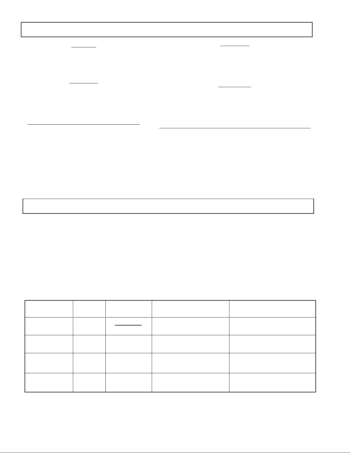
Diagnostic Item No. of times Self-diagnostic display/ Probable Cause Detected Symptoms
Description STANDBY/TIMER Dia
* Power does not turn on Does not li
* +B overcurrent
* Vertical deflection stopped 4 times 4:0 or 4:1 * +13V is not supplied.
* White balance failure 5 times 5:0 or 5:1 * Video OUT
not balanced
OCP
lamp flashes
ht * Power cord is not plugged in. * Power does not come on.
2 times 2:0 or 2:1 * H.OUT (Q502) is shorted. (A board
nostic result Location
* Fuse is burned out (F5050) (E Board
* IC1751 and Q1751 is shorted.
A board) * Has entered standby state after horizontal raster.
* IC 541 is fault
* IC301 is faulty. (A board
* G2 is improperl
A board
Q306 to 308) is faulty. (A board)* No raster is generated.
adjusted. (Note 2
* No power is suppled to the TV.
* AC power suppl
* Power does not come on.
C board)* Load on power line is shorted.
* Vertical deflection pulse is stopped.
* Power line is shorted or power suppl
* CRT cathode current detection reference pulse
output is small.
is faulty.
is stopped.
Note 1: If a +B overcurrent is detected, stoppage of the vertical deflection is detected simultaneously.
The symptom that is diagnosed first by the microcontroller is displayed on the screen.
Note 2: Refer to Screen (G2) Adjustment in Section 3-4 of this manual.
— 4 —
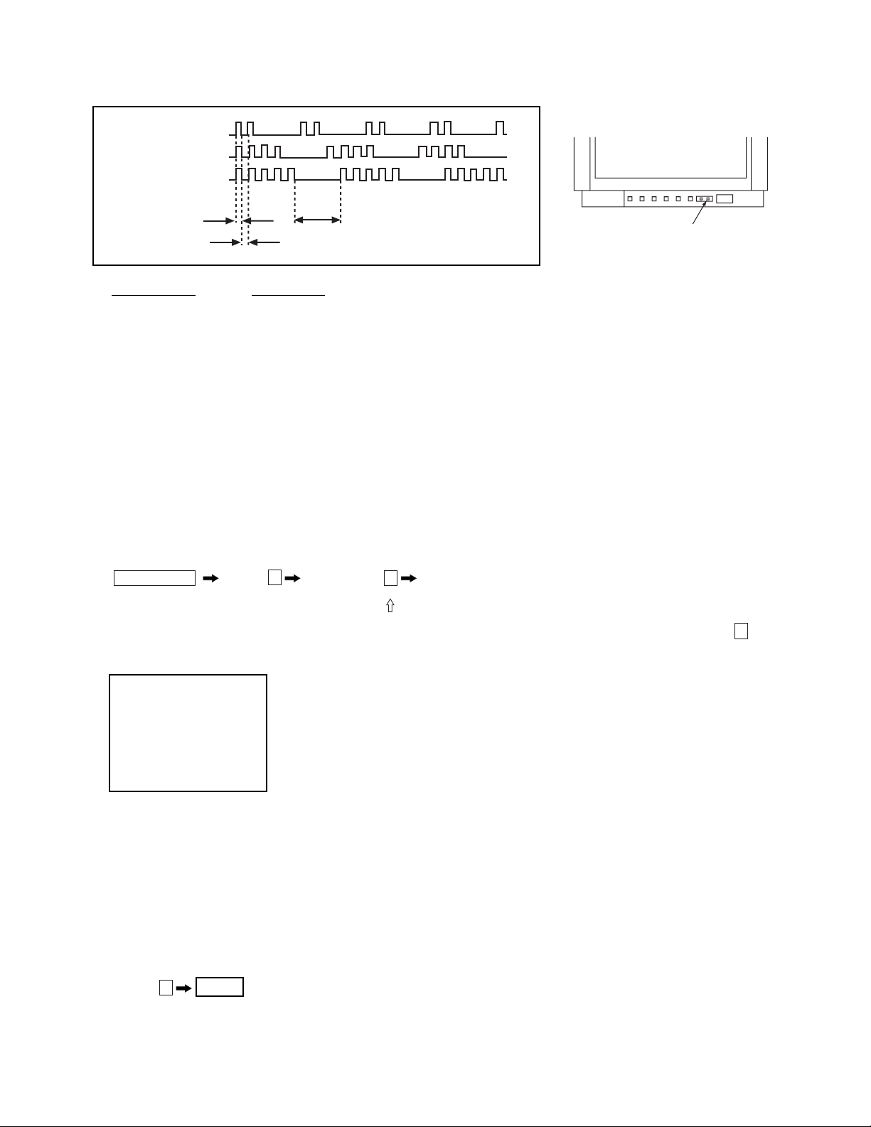
2. DISPLAY OF STANDBY/TIMER LIGHT FLASH COUNT
2 times
4 times
5 times
KV-27S40 / 27S45 / 27S65 / 29SL40 / 29SL40A / 29SL40C/
29SL45 / 29SL65 / 29SL65C/ 29XL40M / 29XL40P / 29XT11A
Lamp ON 0.3 sec.
Lamp OFF 0.3 sec.
Lamp OFF
STANDBY/SLEEP lamp
3 sec.
Diagnostic Item Flash Count*
+B overcurrent 2 times
Vertical deflection stopped 4 times
White balance failure 5 times
* One flash count is not used for self-diagnostic.
3. STOPPING THE STANDBY/TIMER FLASH
Turn off the power switch on the TV main unit or unplug the power cord from the outlet to stop the STANDBY/TIMER lamp from flashing.
4. SELF-DIAGNOSTIC SCREEN DISPLAY
For errors with symptoms such as "power sometimes shuts off" or "screen sometimes goes out" that cannot be confirmed, it is possible to bring up
past occurances of failure for confirmation on the screen:
[To Bring Up Screen Test]
In standby mode, press buttons on the remote commander sequentially in rapid succession as shown below:
Screen display
channel
5
Sound volume
–
Power ON
Note that this differs from entering the service mode (sound volume + ).
Self-Diagnostic screen display
SELF DIAGNOSTIC
2: 0 <-------------
Numeral "0" means that no fault has been detected.
3: N/A 0
4: 0
5: 1 <-------------
Numeral "1" means a fault has been detected one time only.
101: N/A 0
5. HANDLING OF SELF-DIAGNOSTIC SCREEN DISPLAY
Since the diagnostic results displayed on the screen are not automatically cleared, always check the self-diagnostic screen during repairs. When
you have completed the repairs, clear the result display to "0".
Unless the result display is cleared to "0", the self-diagnostic function will not be able to detect subsequent faults after completion of the repairs.
[Clearing the result display]
To clear the result display to "0", press buttons on the remote commander sequentially as shown below when the diagnostic screen is being
displayed.
ENTER
Channel
[Quitting Self-diagnostic screen]
To quit the entire self-diagnostic screen, turn off the power switch on the remote commander or the main unit.
8
— 5 —
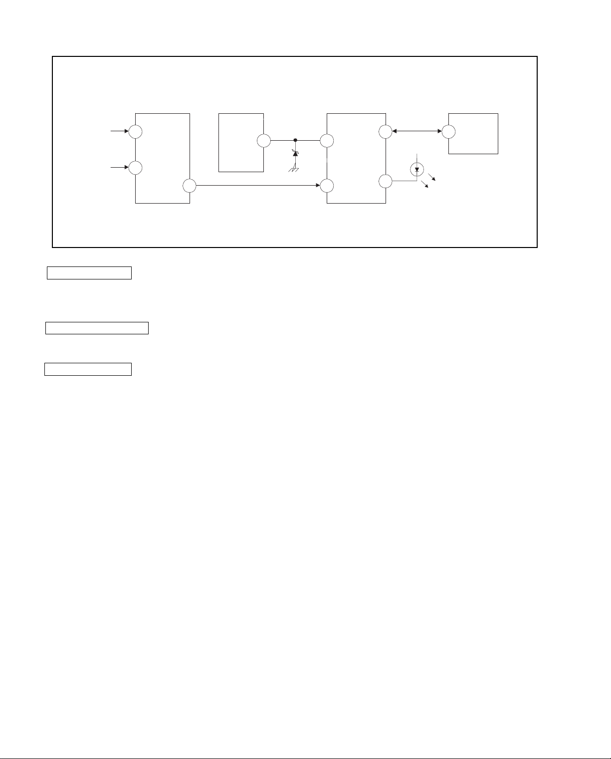
6. SELF-DIAGNOSTIC CIRCUIT
IC001
SYSTEM
17 I-PROT
37 SDAT
36 5
18
O-LED
MEMORY
B-DATIO-BDAT
FROM
CRT
FROM
IC521
PIN 7
IC301
Y/CHROMA JUNGLE
21
IK IN
18
HP/PROTECT
SDA
IC541
V.OUT
3
REF
35
+B overcurrent (OCP) Occurs when an overcurrent on the +B(115V) line is detected by pin 18 of IC301. If the
voltage to pin 18 of IC301 is less than 1V when V.SYNC is more than seven verticals in a
period, the unit will automatically turn off.
Vertical deflection stopped Occurs when an absence of the vertical deflection pulse is detected by pin 17 of IC001.
Power supply will shut down when waveform interval exceeds 2 seconds.
White balance failure If the RGB levels* do not balance within 2 seconds after the power is turned on, this error
will be detected by IC301. TV will stay on, but there will be no picture.
IC003
*(Refers to the RGB levels of the AKB detection Ref pulse that detects IK.)
— 6 —
KV-27S40 / 27S45 / 27S65 / 29SL40 / 29SL40A / 29SL40C/
29SL45 / 29SL65 / 29SL65C/29XL40M / 29XL40P / 29XT11A
SECTION 3
SET-UP ADJUSTMENTS
The following adjustments should be made when a
complete realignment is required or a new picture
tube is installed. These adjustments should be performed
with rated power supply voltage unless otherwise noted.
The controls and switch should be set as follows
unless otherwise noted:
PICTURE control ................. normal
BRIGHTNESS control ......... normal
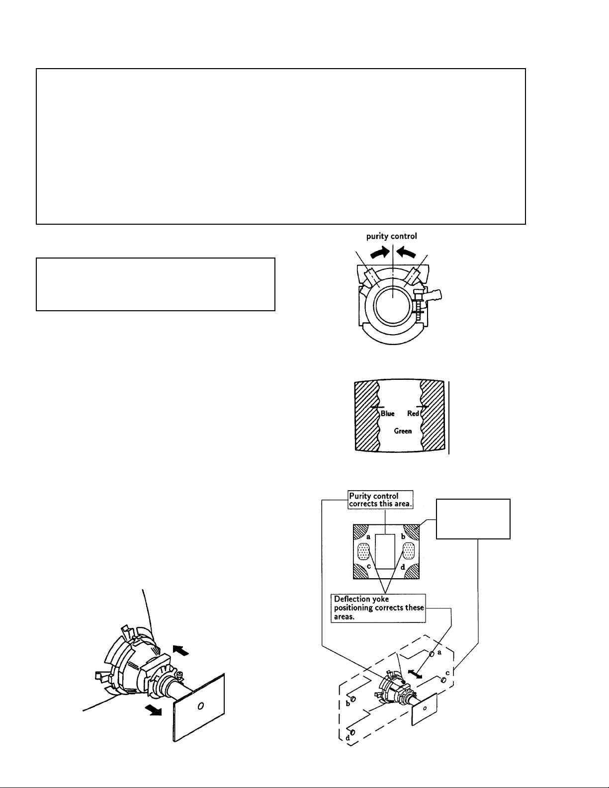
3-1. BEAM LANDING
Preparation:
• Feed in the white pattern signal.
• Before starting, degauss the entire screen.
1. Input a raster signal with the pattern generator.
2. Loosen the deflection yoke mounting screw, and set the
purity control to the center as shown in Fig.2.
Perform the adjustments in order as follows:
1. Beam Landing
2. Convergence
3. Focus
4. Screen (G2) and White Balance
Note: Test Equipment Required
1. Color Bar Pattern Generator
2. Degausser
3. DC Power Supply
4. Digital Multimeter
Fig. 2
3. Turn the raster signal of the pattern generator to
green.
4. Move the deflection yoke backward, and adjust with the
purity control so that green is in the center and red and
blue are at the sides evenly. (Fig.3)
5. Move the deflection yoke forward, and adjust so that the
entire screen becomes green. (Fig.1)
6. Switch over the raster signal to red and blue and confirm
the condition.
7. When the position of the deflection yoke is determined,
tighten it with the deflection yoke mounting screw.
8. When landing at the corner is not right, adjust by using
the disk magnets. (Fig.4)
Fig. 3
Disk magnets or
rotatable disk
magnets correct
these areas (a-d).
Fig. 1
Fig. 4
— 24 —
KV-27S40 / 27S45 / 27S65 / 29SL40 / 29SL40A / 29SL40C/
29SL45 / 29SL65 / 29SL65C/29XL40M / 29XL40P / 29XT11A
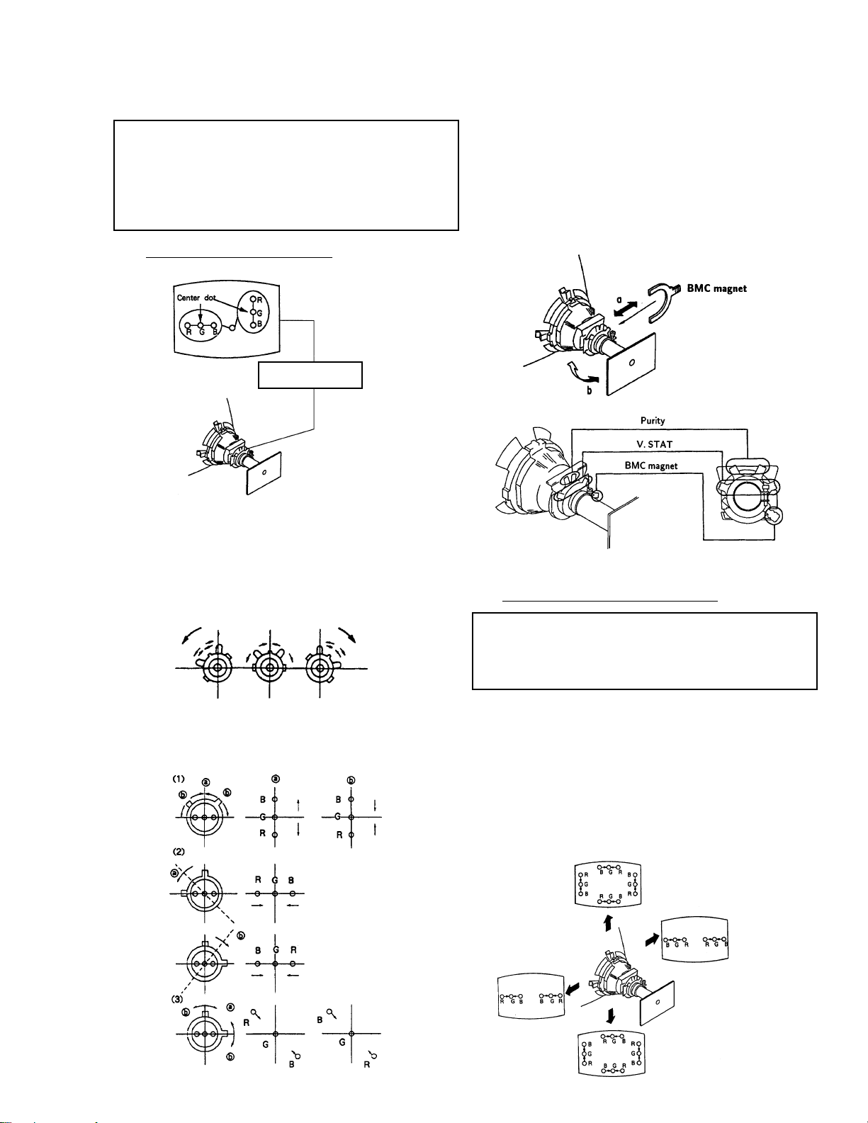
3-2. CONVERGENCE
Preparation:
• Before starting, perform FOCUS, V. LIN and V. SIZE
adjustments.
• Set BRIGHTNESS control to minimum.
• Feed in dot pattern.
(1) Vertical Static Convergence
V. STAT magnet
If the blue dot does not converge with red and green dots,
perform the following steps:
• Move BMC magnet (a) to correct insufficient H. Static
convergence.
• Rotate BMC magnet (b) to correct insufficient V. Static
convergence.
In either case, repeat Beam Landing Adjustment.
BMC magnet
Fig. 6
Fig. 5
1. Adjust V. STAT magnet to converge red, green and blue
dots in the center of the screen. (Vertical movement)
Tilt the V. STAT magnet and adjust static convergence
to open or close the V. STAT magnet.
2. When the V. ST AT magnet is moved in the direction of
arrow a and b, red, green, and blue dots move as
shown below:
Fig. 7
( 2 ) Dynamic Convergence Adjustment
Preparation:
• Before starting, perform Horizontal and Vertical
Static Convergence Adjustment.
1. Slightly loosen deflection yoke screw.
2. Remove deflection yoke spacers.
3. Move the deflection yoke for best convergence as shown
below. ( Fig. 8)
4. Tighten the deflection yoke screw.
5. Install the deflection yoke spacers.
— 25 —
Fig. 8
KV-27S40 / 27S45 / 27S65 / 29SL40 / 29SL40A / 29SL40C/
29SL45 / 29SL65 / 29SL65C/29XL40M / 29XL40P / 29XT11A
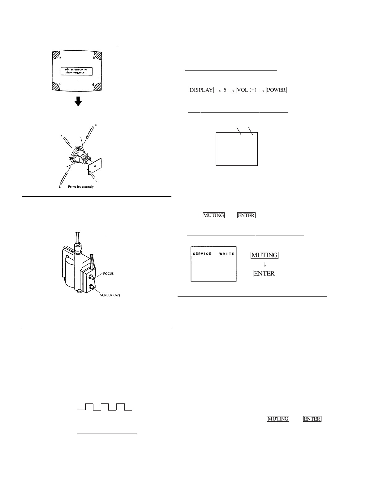
(3) Screen-corner Convergence
Fig. 9
Affix a permalloy assembly corresponding to the misconverged
areas:
3-3. FOCUS
1. Adjust FOCUS control for best picture.
3-5. METHOD OF SETTING THE SERVICE
ADJUSTMENT MODE
(1) SERVICE MODE PROCEDURE
1. Standby mode. (Power off)
2. on the
Remote Commander. (Press each button within a second.)
(2) SERVICE ADJUSTMENT MODE IN
Disp.
Item
(Item)
data
SERVICE AFC 0
3. The CRT displays the item being adjusted.
4. Press 1 or 4 on the Remote Commander to
select the item.
5. Press 3 or 6 on the Remote Commander to
change the data.
6. Press
then to write into memory.
Fig. 10
3-4. SCREEN (G2)
1. Input a dots pattern.
2. Set the PICTURE and BRIGHT controls at minimum
and COLOR control at normal.
3. Adjust SBRT, GCUT, BCUT in service mode with an
oscilloscope as shown in Fig. 11 so that voltages on the red,
green, and blue cathodes are 170Vdc.
N
NN
NN
Fig. 11
GND
170Vdc
170 V dc
NN
NN
N
4. Observe the screen and adjust SCREEN (G2) VR
to obtain the faintly visible background of dot signal.
N
NN
NN
pedestal
(3) SERVICE ADJUSTMENT MODE MEMORY
Green
Red
7. Turn set off and on to exit.
3-6. WHITE BALANCE ADJUSTMENTS
1. Input an entire white signal.
2. Set to Service adjustment Mode.
3. Set DCOL to "0"
4. Set the PICTURE and BRIGHT to minimum.
5. Adjust with SBRT if necessary.
6. Select GCUT and BCUT with 1 and 4 .
7. Adjust with 3 and 6 for the best white balance.
8. Set the PICTURE and BRIGHT to maximum.
9. Select GDRV and BDRV with 1 and 4 .
10. Adjust with 3 and 6 for the best white balance.
11. Reset DCOL to "1".
12. W rite into the memory by pressing
then .
— 26 —
 Loading...