

Sony KV-32S22, KV-29V22M, KV-29SD2, KV-29RS22C, KV-29RS22 User Manual
...
Trinitron" Color TV
Operating Instructions
KV-27S22
KV-27V22
KV-29PS2
KV-29RS22
KV-29RS22C
KV-29SD2
KV-29V22M
KV-32S22
© 1997by SonyCorporation
NARNING
"o prevent fire or shock hazard, do not expose the TV
o rain or moisture,'
ATTENTION
RISQUE DE CHOC ELECTRIQUE,
NE PAS OUVRIR
PRECAUCION
RIESGO DE CHOQUE ELECTRICO
NO ABRIFI
CAUTION: TO REDUCE THE RISK OF ELECTRIC SHOCK,
DO NOT REMOVE COVER (OR BACK).
NO USER-SERVICEABLE PARTS INSIDE.
REFERSERVICING TO QUALIFIED SERVICE PERSONNEL.
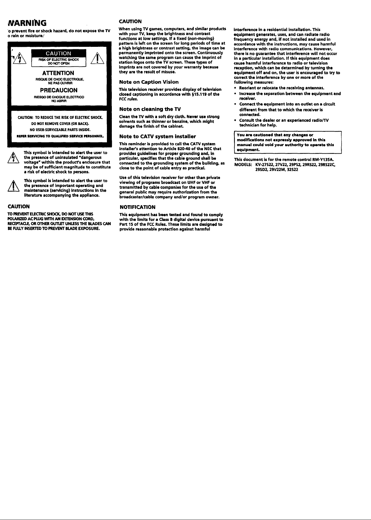
This symbol isintended to alert the user to
the presence of untnsulated "dangerous
voltage" within the product's enclosure that
may be of sufficient magnitude to constitute
a risk of electric shock to persons.
This symbol is intended to alert the user to
the presence of important operating and
maintenance (servicing) instructions in the
literature accompanying the appliance.
CAUTION
TOPREVENTELECTRICSHOCK,DO NOT USETHIS
POLARIZEDAC PLUGWITH AN EXTENSIONCORD,
RECEFTACLE,OROTHEROUTLETUNLESSTHEBLADESCAN
BEFULLYINSERTEDTO PREVENTBLADEEXPOSURE.
CAUTION
When using TV games, computers, and similar products
with your TV, keep the brightness and contrast
functions at low settings. If a fixed (non-moving)
pattern is left on the screen for long periods of time at
a high brightness or contrast setting, the image ran be
permanently imprinted onto the screen. Continuously
watching the same program can cause the imprint of
station Iogos onto the TV screen. These types of
imprints are not covered by your warranty because
they are the result of misuse.
Note on Caption Vision
This television receiver provides display of televbion
dosed captioning in accordance with §15.119 of the
FCC rules.
Note on cleaning the TV
Clean the TV with a soft dry cloth. Never use strong
solvents such as thinner or benzine, which might
damage the finish of the cabinet.
Note to CATV system installer
This reminder is provided to call the CATV system
installer's attention to Artide 820-40 of the NEC that
provides guidelines for proper grounding and, In
particular, specifies that the cable ground shall be
connected to the grounding system of the building, as
close to the point of cable entry as practical.
Use of this television receiver for other than private
viewing of programs broadcast on UHF or VHF or
transmitted by cable companies for the use of the
general public may require authorization from the
broedcaster/cable company and/or program owner.
NOTIFICATION
This equipment has been tested and found to comply
with the limits for a Class B digital device pursuant to
Part 15 of the FCC Rules. These limits are designed to
provide reasonable protection against harmful
interference in a residential installation. This
equipment generates, uses, and can radiate radio
frequency energy and, if not installed and used in
accordance with the instructions, may cause harmful
interference with radio communications. However,
there is no guarantee that interference will not occur
in a particular installation. If this equipment does
cause harmful interference to radio or television
reception, which can be determined by turning the
equipment off and on, the user isencouraged to try to
correct the interference by one or more of the
following measures:
• Reorient or relocate the receiving antennas.
• Increase the separation between the equipment end
receiver.
• Connect the equipment into an outlet on a circuit
different from that to which the receiver is
connected.
• Consult the dealer or an experienced radio/TV
technician for help.
modifications not expressly approved in this
manual could void your authority to operate this
I You are cautioned that any changes or I
equipment.
This document is for the remote control RM-Y13SA.
MODELS: KV-27S22, 27V22, 29PS2, 29RS22, 29RS22C,
2951)2, 29V22M, 32S22
I
JrRemote Control
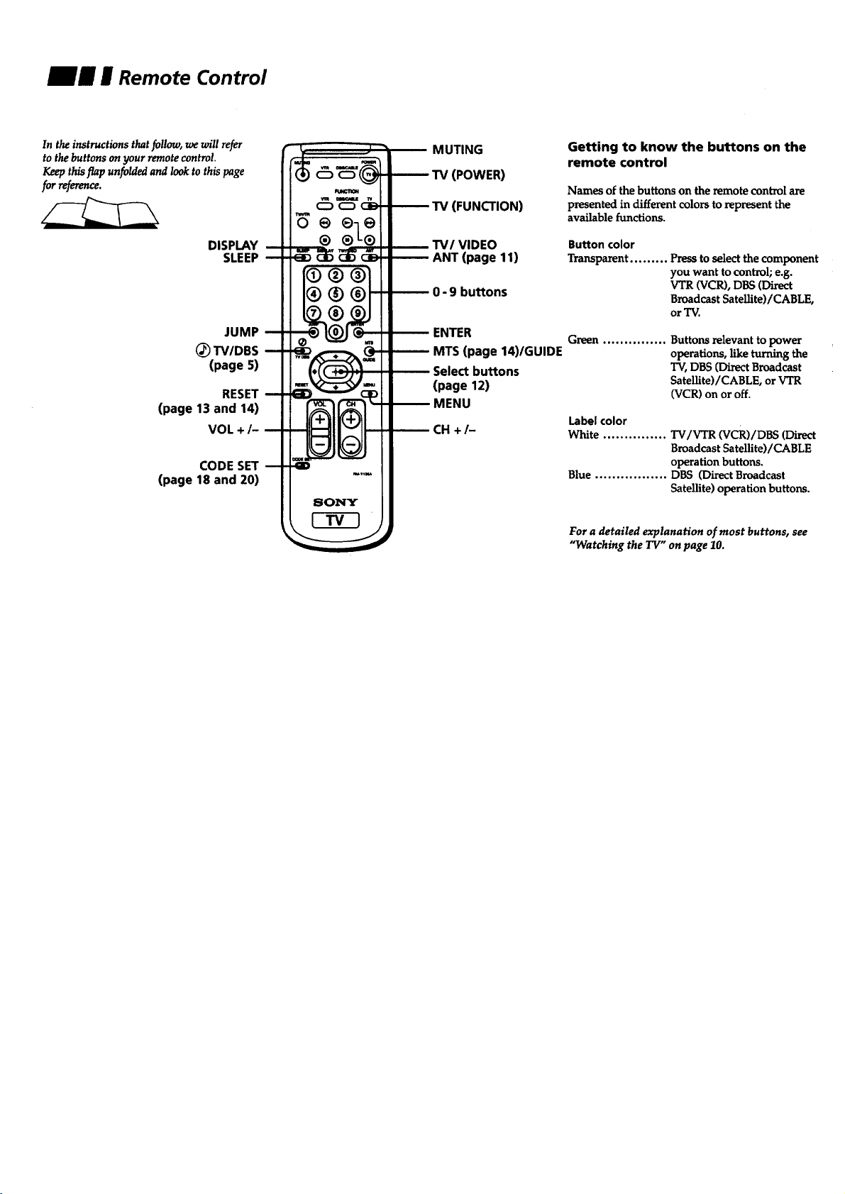
In the instructions that follow, we will refer
to the buttons on your remote control.
Keep this flap unfolded and look to this page
for reference.
DISPLAY
SLEEP
JUMP
(_ TV/DBS
(page 5)
RESET
(page 13 and 14)
VOL +/-
CODE SET
(page 18 and 20)
o @eo
® ®-L®
MUTING
TV (POWER)
TV (FUNCTION)
TV/VIDEO
ANT (page 11)
0- 9 buttons
ENTER
MTS (page 14)/GUIDE
Select buttons
(page 12)
MENU
CH +/-
Getting to know the buttons on the
remote control
Names of the buttons on the remote control are
presented in different colors to represent the
available functions.
Button color
Transparent ......... Press to select the component
you want to control; e.g.
VTR (VCR), DBS (Direct
Broadcast Satellite)/CABLE,
or "IV.
Green ............... Buttons relevant to power
operations, like turning the
TV, DBS (Direct Broadcast
SateUite)/CABLE, or VTR
(VCR) on or off.
Label color
White ............... TV/VTR (VCR)/DBS (Direct
Broadcast Satellite)/CABLE
operation buttons.
Blue ................. DBS (Direct Broadcast
Satellite) operation buttons.
For a detailed explanation of most buttons, see
"Watching the TV" on page 10.
mm w Table of Contents
Welcome! ........................................ 1
Precautions ...................................... 1
Using This Manual .......................... 1
Connecting and Installing the TV
Connector Types .......................................... 2
Making Connections ................................... 2
Connecting directly to cable
oran antenna ....................................... 2
Cable orantenna ...................................... 2
Connecting a cable box ............................ 2
Connsctinganantenna/cableTVsystem
withaVCR .......................................... 3
Connect_toans Videoequipped
VCR ..................................................... 3
Connecting a VCR and "IVwith a cable
bOX .,,,,.,....,,,,,,....,,..,......,.. ...... °°°.°..°.°°°°°4
ConnectingtoanSVideoeqm'ppedVCR
with a cable box ................................. 4
Connecting a DBS receiver ...................... 5
Conneding a DBS receiver and a VCR .... 5
Connscfi_ an a_M.iosystem ................... 6
Connecting a camcorder .......................... 6
two vcP,sfortape_iiting
using MONITOR our ....................... 7
Basic Set Up
InseKmgbatteries...........................................8
Using the remotecontrol Select buttons .......8
Adjus_ng sliders ............................................8
On LineHelp/Instructions ............................8
Using your New TV
Settingup the'IV automatically....................9
Watchingthe"IV.......................................... 10
Adjusting your SET UP (menus)
Learning menu selection .............................. 12
Using the VIDEO menu ............................... 13
Using the AUDIO menu .............................. 14
Using the TIMER menu ............................... 15
Using the SET UP menu ............................. 16
Operating video equipment
Settingthemanufacturer'scode...................18
Operating a cable box or DB$ receiver
ProgrammL_theremote.............................20
Troubleshooting ........................... 21
Specifications ................................ 23
Index .............................................. 24
Owner's Record
The model and serial numbers are Io¢ated at the rear
of the W, below the Sony logo, on the stkker, end
also on the TV box (white label). Record the_ numbers
in the spaces provided below. Refer to them whenever
you call upon your Sony dealer regarding this product.
Model No. KV"
serial No.
E Welcome!
E Precautions
Jig E Using This Manual
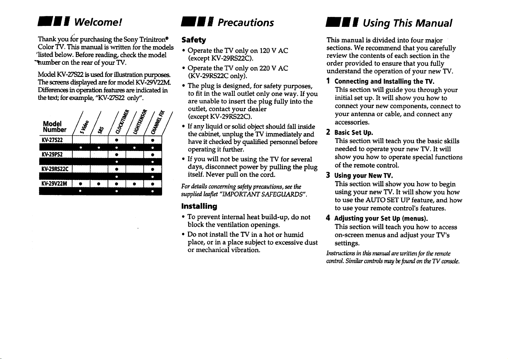
Thank you for purchasing the Sony Trinitron®
Color TV. This manual is written for the models
'listed below. Before reading, check the model
"humber on the rear of your TV.
Model KV-27S22 is used for illustration purposes.
The screens displayed are for model KV-29V22M.
Differences in operation features areindicated in
the text;for example, "KV-27S22 only".
Model
Number
KV-27S22
k'V-29PS2
KV-29RS22C
k'V-29V22M
Safety
* Operate the TV only on 120 V AC
(except KV-29RS22C).
. Operate the TV only on 220 V AC
(KV-29RS22C only).
* The plug is designed, for safety purposes,
to fit in the wall outlet only one way. If you
are unable to insert the plug fully into the
outlet, contact your dealer
(except KV-29RS22C).
• If any liquid or solid object should fall inside
the cabinet, unplug the TV immediately and
have it checked by qualified personnel before
operating it further.
• If you will not be using the TV for several
days, disconnect power by pulling the plug
itself. Never pull on the cord.
For details concerning safety precautions, see the
supplied leaflet "IMPORTANT SAFEGUARDS".
Installing
• To prevent internal heat build-up, do not
block the ventilation openings.
• Do not install the TV in a hot or humid
place, or in a place subject to excessive dust
or mechanical vibration.
This manual is divided into four major
sections. We recommend that you carefully
review the contents of each section in the
order provided to ensure that you fully
understand the operation of your new TV.
1 Connecting and Installing the W.
This section will guide you through your
initial set up. It will show you how to
connect your new components, connect to
your antenna or cable, and connect any
accessories.
2 Basic Set Up.
This section will teach you the basic skills
needed to operate your new TV. It will
show you how to operate special functions
of the remote control.
3 Using your New W.
This section will show you how to begin
using your new TV. It will show you how
to use the AUTO SET UP feature, and how
to use your remote control's features.
4 Adjusting your Set Up (menus).
This section will teach you how to access
on-screen menus and adjust your TV's
settings.
Instructions in this manual are written for the remote
wntrol. Similar controls may befound on the TV console.
__ II Connecting and Installing the TV
Connector Types
You may find it necessary to use some of the
following connector types during set up.
Coaxial Cable
Standard TV Cable and Antenna connector
Plug Type
_ (_ Press onto connection
Screw-onType
-'_ CI_ Screwontoconnection
S Video Cable
High quality Video connector for enhanced
picture quality
-.__) Alignguidesand
pressontoconnection
Audio/Video Cable
Conventional Audio/Video cable
_ _ Press onto connection
Yellow - Video
White - Audio (Left)
Red - Audio (Right)
Making Connections
For best picture quality, a cable TV system or
outdoor antenna is recommended.
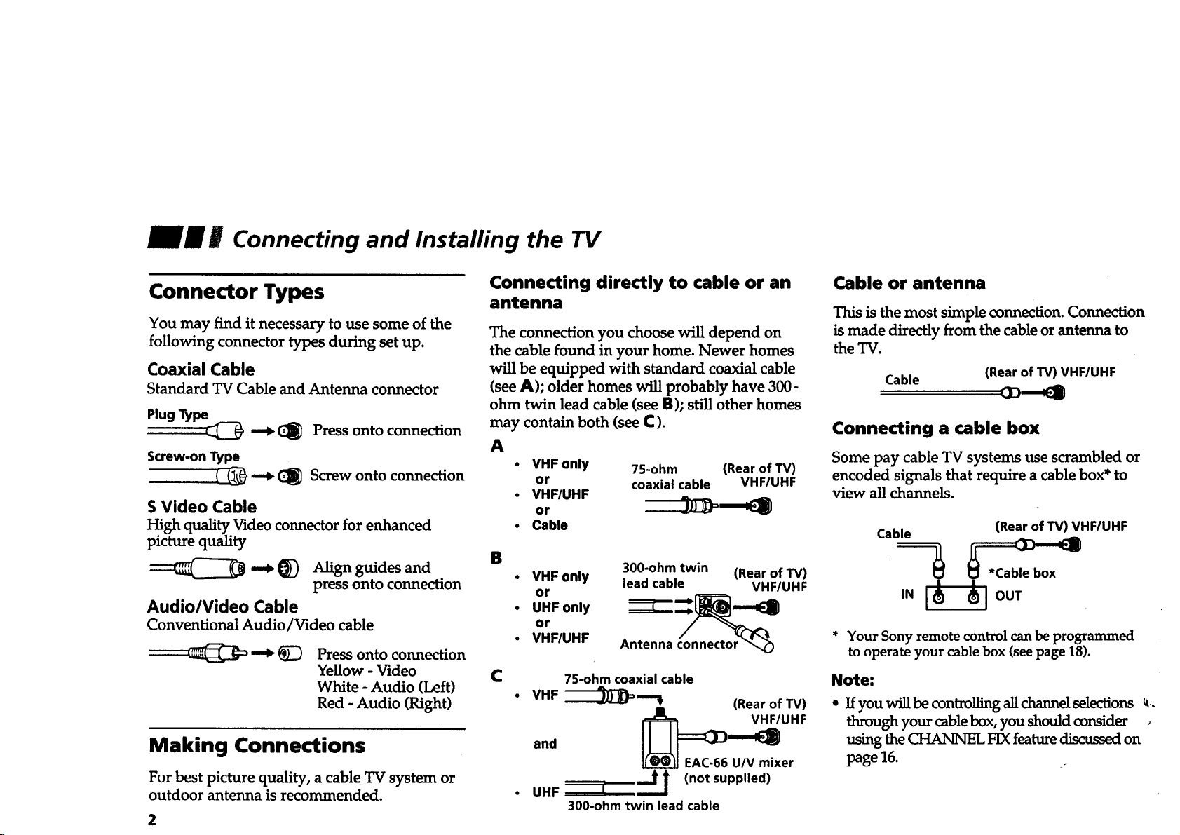
Connecting directly to cable or an
Cable or antenna
antenna
This is the most simple connection. Connection
The connection you choose will depend on
the cable found in your home. Newer homes
will be equipped with standard coaxial cable
(see A); older homes will probably have 300-
ohm twin lead cable (see B); still other homes
may contain both (see C).
A
• VHF only 75-ohm (Rear of TV)
or coaxial cable VHF/UHF
• VHF/UHF
or
i Cable Cable _ (Rear of TV) VHF/UHF
B 300-ohm twin (Rear of TV) ox
VHF only lead cable VHF/UHF _ '
or ,N OUT
• UHF only
or
• VHF/UHF Antenna connector _ * Your Sony remote control can be programmed
C 7S-ohm coaxial cable Note:
VHF
-'---'JJ)-)_= "% (Rear of TV)
_ EAC-66 U/V mixer
(not
• UHF I
300-ohm twin lead cable
supplied)
is made directly from the cable or antenna to
the TV.
Cable
(Rear of TV) VHF/UHF
Connecting a cable box
Some pay cable TV systems use scrambled or
encoded signals that require a cable box* to
view all channels.
to operate your cable box (see page 18).
• If you will be controlling all channel selections _,.
through your cable box, you should consider ,
usingthe CHANNEL FIX featurediscussedon
page 16.
Disconnect all power sources before making any connections.
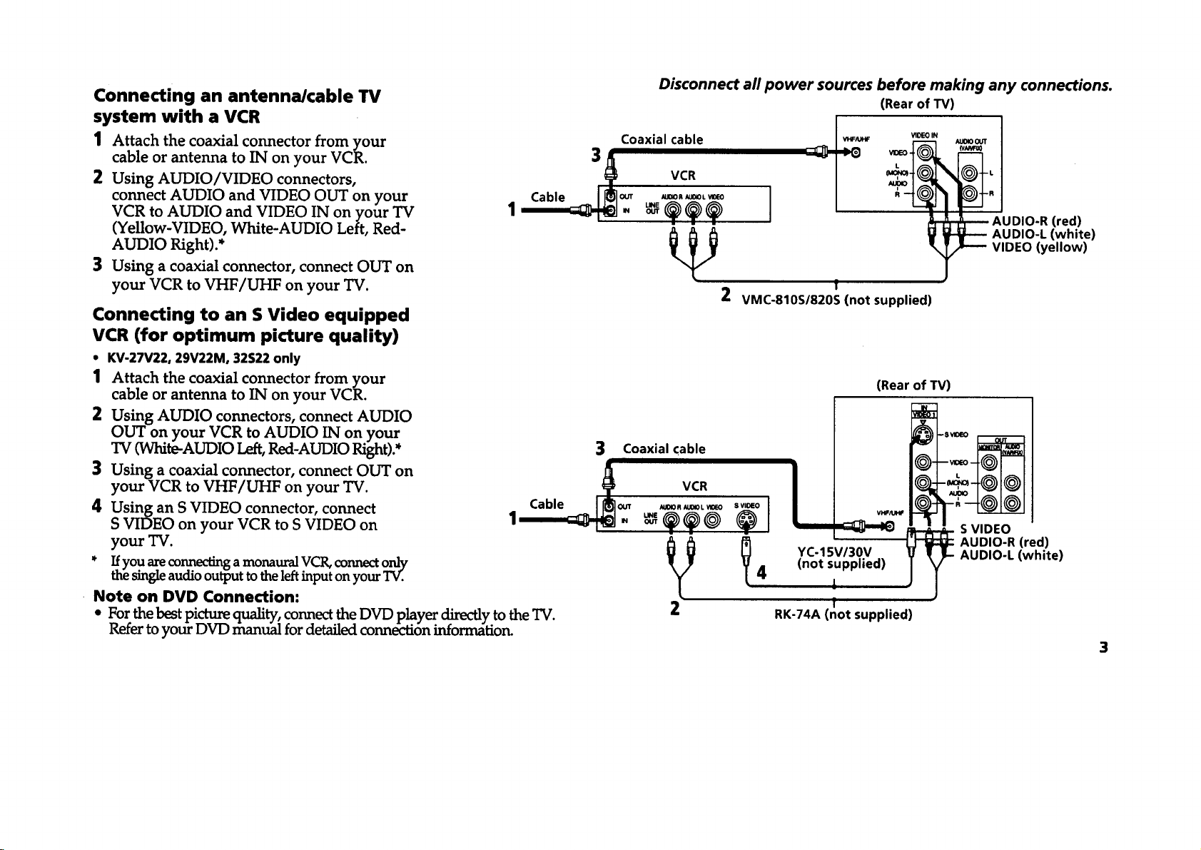
Connecting an antenna/cable TV (Rear of TV)
1 Attach the coaxial connector from your Coaxial cable _o_ _ao0_
cable or antenna to IN on your VCR. 3
2 Using AUDIO/VIDEO connectors, VCR
connect AUDIO and VIDEO OUT on your Cable II[_1out u_oR,ax0__o I
VCR to AUDIO and VIDEO IN on your TV 1 '__-_ - _ _.._ ._ I " --_-_"
AUDIO Right).* VIDEO (yellow)
(Yellow-VIDEO, White-AUDIO Left, Red- _ _ AUDIO-R (red)
3 Using a coaxial connector, connect OUT on
f
your VCR to VHF/UHF on your TV. 2 VMC-810S/820S (not supplied)
Connecting to an S Video equipped
VCR (for optimum picture quality)
• KV-27V22, 29V22M, 32S22 only
1 Attach the coaxial connector from your
cable or antenna to IN on your VCR.
2 Using AUDIO connectors, connect AUDIO
OUT on your VCR to AUDIO IN on your
TV (White-AUDIO Left, Red-AUDIO Right).*
3 Using a coaxial connector, connect OUT on
your VCR to VHF/UHF on your TV.
4 Using an S VIDEO connector, connect
S VIDEO on your VCR to S VIDEO on
3 Coaxial cable
Cable /_]o_ _0._0L_o
1_- _._@ "(_° I
(Rear of TV)
VHF/U_
yourTV.
* Ifyou are connecting a monaural VCR, connect only
the single audio output to the left input on your TV.
Note on DVD Connection:
* For the best picture quality: connect the DVD player directly to the TV. 2
Keter to your DVD manual for detailed connection information.
_/_ _ YC-15V/30V
4 (not supplied)
1
f
RK-74A (not supplied)
AUDIO-L (white)
AUDIO-R (red)
AUDIO-L (white)
S VIDEO
3
_m i__' Connecting and Installing the TV (continued)
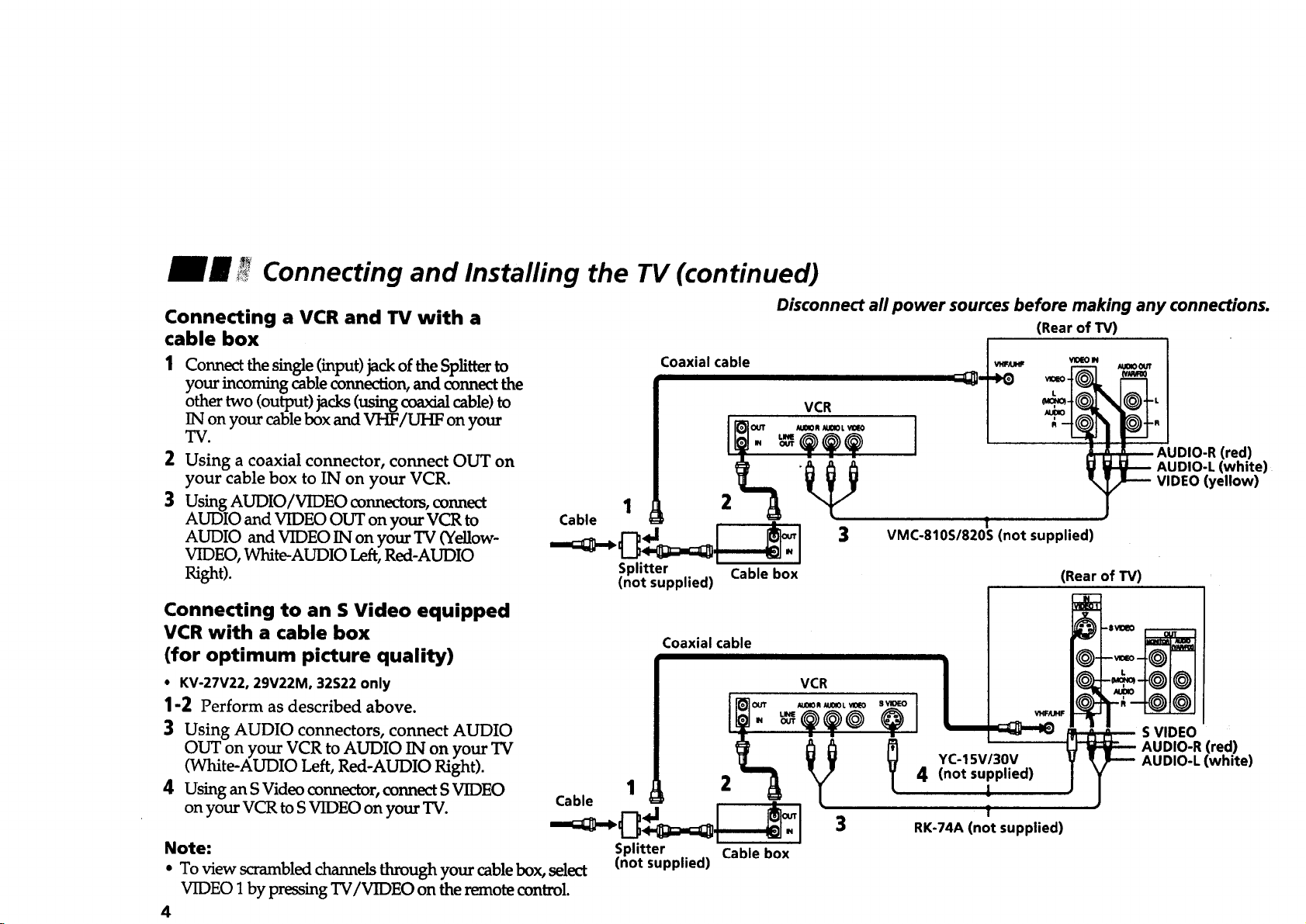
Connecting a VCR and TV with a
cable box
Connect the single (input) jack of the Splitter to
your incoming cable connection, and connect the
other two (output) jacks (using coaxial cable) to
IN on your cable box and VHF/UHF on your
TV.
2
Using a coaxial connector, connect OUT on
your cable box to IN on your VCR.
3 Using AUDIO/VIDEOconnectors, connect 1
AUDIO and VIDEO OUT on your VCR to Cable
AUDIO and VIDEO IN on your TV (Yellow-
VIDEO, White-AUDIO Left, Red-AUDIO
Right).
Connecting to an S Video equipped
VCR with a cable box
(for optimum picture quality)
• KV-27V22, 29V22M, 32S22 only
1-2 Perform as described above.
3 Using AUDIO connectors, connect AUDIO
OUT on your VCR to AUDIO IN on your TV
(White-AUDIO Left, Red-AUDIO Right).
4 Using an S Video connector, connect S VIDEO
on your VCR to S VIDEO on your TV.
Note: Splitter Cable box
• To view s_ambled channels through your cable box, select (not supplied)
VIDFO 1 by pressing TV/VIDI_O on the remote control.
4
Cable 1 4J 2 _ _
Coaxial cable
.I "o_
Splitter Cable box
(not supplied)
Coaxial cable
I'_OUT _UOlOR _01OL VlO_
Disconnect all power sources before making any connections.
(Rear of TV)
VCR
AUDIO-L (white)
VIDEO (yellow)
S VIDEO
AUDIO-R (red)
AUDIO-L (white)
VCR
] OD,O-RCred)
VMC-810S/820S (not supplied)
I
4 (not supplied)
RK-74A (not supplied)
!
(Rear of TV)
YC-15V/30V
!
f
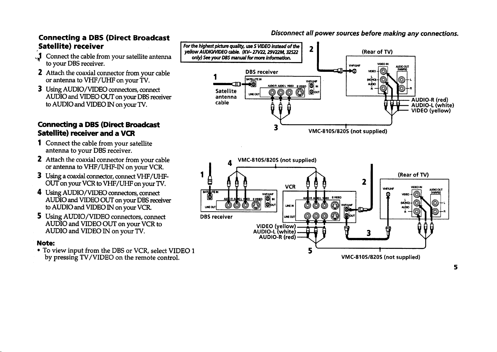
Connecting a DBS (Direct Broadcast
Satellite) receiver
.,_1 Connect the cable from your satellite antenna
to your DBS receiver.
2 Attach the coaxial connector from your cable
or antenna to VHF/UHF on your TV.
3 Using AUDIO/VIDEO connectors, connect
AUDIO and VIDEO OUT on your DBS receiver
to AUDIO and VIDEO IN on your TV.
Connecting a DBS (Direct Broadcast
Satellite) receiver and a VCR
Forthehighestpicturequality,useS VIDEOinsteadof the I 2 I
yeIIow AUDtO/VIDEO cable. (KV- 27V22, 29V22M, 32S22 I |
1 Connect the cable from your satellite
antenna to your DBS receiver.
2 Attach the coaxial connector from your cable
or antenna to VHF/UHF-IN on your VCR.
3 Using a coaxial connector, connect VHF/UHF-
OUT on your VCR to VHF/UHF on your TV.
4 Using AUDIO/VIDEO connectors, connect
AUDIO and VIDEO OUT on your DBS receiver
to AUDIO and VIDEO IN on your VCR.
5 Using AUDIO/VIDEO connectors, connect
AUDIO and VIDEO OUT on your VCR to
AUDIO and VIDEO IN on your TV.
Note:
• To view input from the DBS or VCR, select VIDEO 1
by pressing TV/VIDEO on the remote control.
Disconnect all power sources before making any connections.
(Rear of TV)
on_) See your DBSmanual for more informatlon. I I Iv,.,.
Satellite I _ L_I /
antenna [u__ ] /
cable
3_ AUDIO-L (white)
VMC-810S/820S (not supplied)
(not supplied)
f
VIDEO IN
R
oBsr-- I !
AUDIO-L (white) _ 3
AUDIO-R (red)
VIDEO (yellow)
5 1
VMC-810S/820S (not supplied)
VIDEO (yellow)
_ AUDIO-R (red)
(Rear of TV)
LV_O I _1 (V.,U',,'_OI.
N_r°
5
 Loading...