

SONY KV-29LS60E, KV-29LS60K, KV-29LS60B SERVICE MANUAL
SERVICE MANUAL
AE-6B
CHASSIS
MODEL COMMANDER DEST CHASSIS NO.
KV-29LS60B RM-932 FR SCC-Q83A-A
KV-29LS60E RM-932 ESP SCC-Q81A-A
MODEL COMMANDER DEST CHASSIS NO.
KV-29LS60K RM-932 OIRT SCC-Q82B-A
KV-29LS60
- 1 -
RM-932

TABLE OF CONTENTS
Section Title Pag e Section Title Pag e
Specifications .................... 3
Connectors .................... 4
Self Diagnostic Software .................... 5
1. GENERAL
Switching On the TV and
Automatically Tuning .................... 6
Introducing the Menu System .................... 7
Menu Guide .................... 7
T elete xt .................... 9
Remote Control Configuration
for VCR/DVD .................... 9
Specifications .................... 10
Troubleshooting .................... 10
2. DISASSEMBLY
2-1. Rear Cover Removal .................... 11
2-2. Speaker Disconnection .................... 11
2-3. Chassis Removal .................... 11
2-4. Service Position .................... 12
2-5. D and G Board Removal .................... 12
2-6. Side Control Module Removal .................... 12
2-7. H2 Board Removal .................... 12
2-8. M Board Removal .................... 13
2-9. Service Connector for M Board.................... 13
2-10. Picture Tube Removal .................... 14
Bottom Plates .................... 15
3. SET-UP ADJUSTMENTS
3-1. Beam Landing .................... 16
3-2. Convergence .................... 17
3-3. Focus Adjustment .................... 19
3-4. Screen (G2), White Balance .................... 19
5. DIAGRAMS
5-1. Block Diagrams (1) .................... 23
Block Diagrams (2) .................... 24
Block Diagrams (3) .................... 25
Block Diagrams (4) .................... 26
5-2. Circuit Board Location .................... 26
5-3. Schematic Diagrams and
Printed Wiring Boards .................... 26
* A Board Schematic .................... 27
* A Board PWB .................... 29
* VM Board Schematic.................... 33
* VM Board PWB .................... 31
* F2 Board Schematic .................... 33
* F2 Board PWB .................... 34
* H2 Board Schematic .................... 33
* H2 Board PWB .................... 34
* G Board Schematic .................... 35
* G Board PWB .................... 34
* D Board Schematic .................... 36
* D Board PWB .................... 37
* C Board Schematic .................... 38
* C Board PWB .................... 39
* M Board Schematic .................... 40
* M Board PWB .................... 39
5-4. Semiconductors .................... 41
5-5. IC Blocks .................... 44
6. EXPLODED VIEWS
6-1. Chassis .................... 46
6-2. Picture Tube .................... 47
7. ELECTRICAL PARTS LIST .................... 48
4. CIRCUIT ADJUSTMENTS
4-1. Electrical Adjustments .................... 20
4-2. T est Mode 2 .................... 22
CAUTION
SHORT CIRCUIT THE ANODE OF THE PICTURE TUBE AND THE
ANODE CAP TO THE METAL CHASSIS, CRT SHIELD, OR THE
CARBON PAINTED ON THE CRT, AFTER REMOVAL OF THE
ANODE CAP.
WARNING !!
AN ISOLATION TRANSFORMER SHOULD BE USED DURING
ANY SERVICE WORK TO AVOID POSSIBLE SHOCK HAZARD
DUE TO LIVE CHASSIS, THE CHASSIS OF THIS RECEIVER IS
DIRECTLY CONNECTED TO THE POWER LINE.
SAFETY-RELATED COMPONENT WARNING !!
COMPONENTS IDENTIFIED BY SHADING AND MARKED ON
THE SCHEMATIC DIAGRAMS, EXPLODED VIEWS AND IN THE
PARTS LIST ARE CRITICAL FOR SAFE OPERATION. REPLACE
THESE COMPONENTS WITH SONY PARTS WHOSE PART
NUMBERS APPEAR AS SHOWN IN THIS MANUAL OR IN
SUPPLEMENTS PUBLISHED BY SONY.
ATTENTION
APRES AVOIR DECONNECTE LE CAP DE’LANODE,
COURT-CIRCUITER L’ANODE DU TUBE CATHODIQUE ET
CELUI DE L’ANODE DU CAP AU CHASSIS METALLIQUE DE
L’APPAREIL, OU AU COUCHE DE CARBONE PEINTE SUR LE
TUBE CATHODIQUE OU AU BLINDAGE DU TUBE
CATHODIQUE.
ATTENTION !!
AFIN D’EVITER TOUT RISQUE D’ELECTROCUTION
PROVENANT D’UN CHÁSSIS SOUS TENTION, UN
TRANSFORMATEUR D’ISOLEMENT DOIT ETRE UTILISÈ LORS
DE TOUT DÈPANNAGE LE CHÁSSIS DE CE RÈCEPTEUR EST
DIRECTMENT RACCORDÈ Á L’ALIMENTATION SECTEUR.
ATTENTION AUX COMPOSANTS RELATIFS Á
LA SECURITÈ!!
LES COMPOSANTS IDENTIFIÈS PAR UNE TRAME ET PAR UNE
MARQUE SUR LES SCHÈMAS DE PRINCIPE, LES VUES
EXPLOSÈES ET LES LISTES DE PIECES SONT D’UNE IMPOR-
TANCE CRITIQUE POUR LA SÈCURITÈ DU FONCTIONNEMENT,
NE LES REMPLACER QUE PAR DES COMPSANTS SONY DONT
LE NUMÈRO DE PIÈCE EST INDIQUÈ DANS LE PRÈSENT
MANUEL OU DANS DES SUPPLÈMENTS PUBLIÈS PAR SONY.
- 2 -
LEDOMMETI metsySnoisiveleT metsySoeretS egarevoClennahC metsySroloC
01F-2F,21E-2E:FHV
96B-12B,96F-12F,96E-12E:FHU
Q-B,02S-1S,30S-10S:VTELBAC
14S-12S:REPYH
96E-12E:FHU
02S-1S,30S-10S:VTELBAC
14S-12S:REPYH
21R-10R,21E-2E:FHV
96R-12R,96E-12E:FHU
02S-1S,30S-10S:VTELBAC
14S-12S:REPYH
BL,I,K/D,H/G/B
EH/G/B
KK/D,H/G/B
MACIN/NAMREG
oeretS
21E-2E:FHV
MACIN/NAMREG
oeretS
MACIN/NAMREG
oeretS
MACES,LAP
85.3CSTN,34.4CSTN
)NIOEDIV(
MACES,LAP
85.3CSTN,34.4CSTN
)NIOEDIV(
MACES,LAP
85.3CSTN,34.4CSTN
)NIOEDIV(
ebuTerutciP
rotcennocoruEnip-12:1
)dradnatsCELENEC(
rotcennocoruEnip-12:2
skcaJonohPoiduArofelbairavsrotcennoCtuptuO
kcajenohpdaeHkcajinimoerets
stupnioiduAskcajonohp
stupnioediVskcajonohp
tupnioediVSNIDnip4
nortinirTDF
)sehcni92(mc27xorppA
derusaemerutcipmc86xorppA(
)yllanogaid
noitcelfedeerged401
]RAER[slanimreTtuptuO/tupnI snoitacificepSlareneG
.slangisoediVdnaoiduArofstupnI
.BGRrofstupnI
oiduAdnaoediVVTfostuptuO
.slangis
.slangisoediVdnaoiduArofstupnI
.BGRrofstupnI
.slangisoiduAdnaoediVVTfostuptuO
)elbatceles(
slangiS
]EDIS[slanimreTtuptuO/tupnI
tuptuodnuoS
rekaepstfeLdnathgiR
refooWbuS
stnemeriuqeRrewoPV042-022
noitpmusnoCrewoPW031
snoisnemiDmm355x295x177xorppA
thgieWgk94xorppA
seirosseccAdeilppuS
serutaeFrehtO
stnemeriuqerrewoP
)SMR(W01x2)rewoPcisuM(W02x2
)SMR(W51x1)rewoPcisuM(W03x1
)1(rednammoCetomeR239-MR
)2(yrettab6RdetangisedCEI
,noitcetedotuAmetsysVT,erutcipzH001
ybloDlautriV,EBB,kniltramS,txeteleT
lortnoCderarfnI:metsySlortnoCetomeR
cdV3
noitangisedCEIseirettab2
)AAezis(6R
.ecitontuohtiwegnahcottcejbuserasnoitacificepsdnangiseD
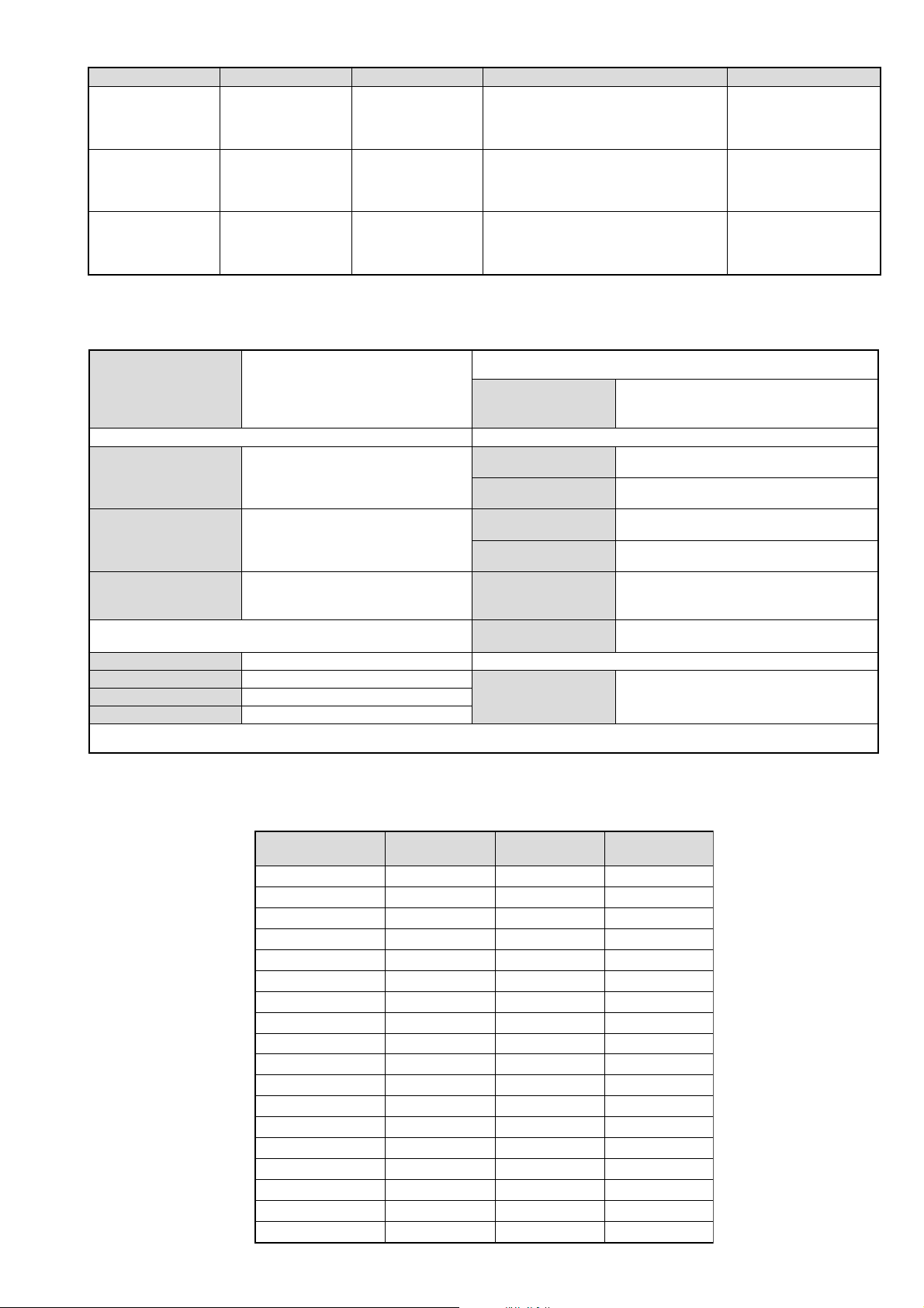
metI
emaNledoM
bmoClaPFFOFFOFFO
PIPFFOFFOFFO
ytiroirPBGRNONONO
xoBrefooWNONONO
1tracSNONONO
2tracSNONONO
)3(nitnorFNONONO
4tracSFFOFFOFFO
rotcejorPFFOFFOFFO
G/BmroNNONONO
ImroNNOFFOFFO
K/DmroNNONONO
SUAmroNFFOFFOFFO
LmroNNOFFOFFO
TASmroNFFOFFOFFO
MmroNFFOFFOFFO
txeteleTNONONO
oeretSmaciNNONONO
B06SL92-VK E06SL92-VK K06SL92-VK
- 3 -
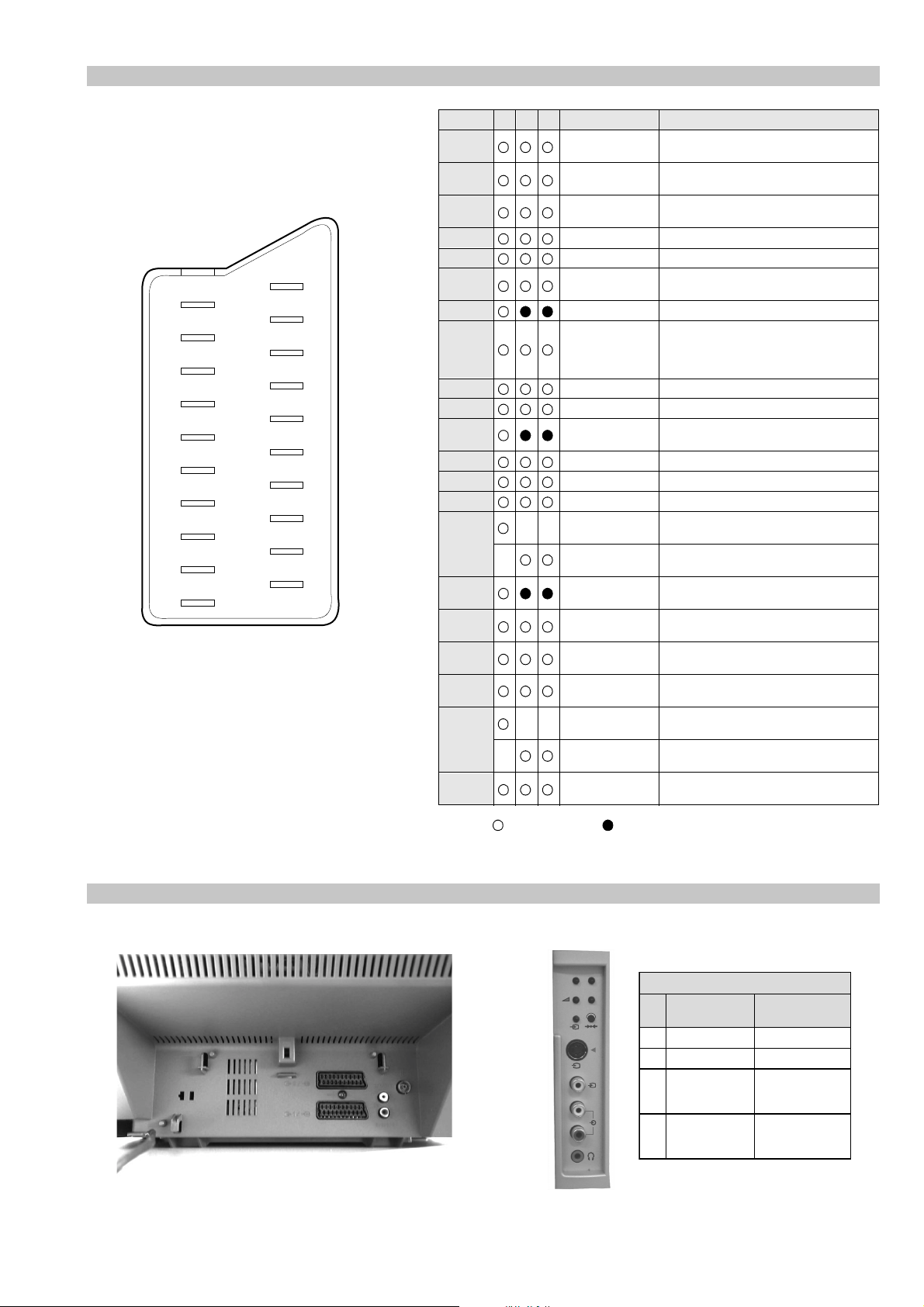
21 pin connector
21
19
17
15
13
11
9
7
5
3
1
20
18
16
14
12
10
8
6
4
2
Pin No 1 2 4 Signal Signal level
1 Audio output B
2
3
4 Ground (audio)
5 Ground (blue)
6 Audio input A
7 Blue input 0.7 +/- 3dB, 75 ohms positive
8 Function select
9 Ground (green)
10 Open
11 Green Green signal : 0.7 +/- 3dB, 75 ohms,
12 Open
13 Ground (red)
14 Ground (blanking)
15
16 Blanking input
17 Ground (video
18 Ground (video
19 Video output 1V +/- 3dB, 75ohms, positive sync 0.3V
20
21 Common ground
3
(right)
Audio input B
(right)
Audio output A
(left)
(left)
(AV control)
_ _ Red input 0.7 +/- 3dB, 75 ohms, positive
_ (S signal Chroma
input)
(Ys signal)
output)
input)
_ _ Video input 1V +/- 3dB, 75ohms, positive sync 0.3V
_ Video input
Y (S signal)
(plug, shield)
Standard level : 0.5V rms
Output impedence : Less than 1kohm*
Standard level : 0.5V rms
Output impedence : More than 10kohm*
Standard level : 0.5V rms
Output impedence : Less than 1kohm*
Standard level : 0.5V rms
Output impedence : More than 10kohm*
High state (9.5-12V) : Part mode
Low state (0-2V) : TV mode
Input impedence : More than 10K ohms
Input capacitance : Less than 2nF
positive
0.3 +/- 3dB, 75 ohms, positive
High state (1-3V) Low state (0-0.4V)
Input impedence : 75 ohms
(-3+10dB)
(-3+10dB)
1V +/- 3dB, 75ohms, positive sync 0.3V
(-3+10dB)
Connected Not Connected (open) * at 20Hz - 20kHz
Rear Connection Panel Side Connection Panel
p
- +
niP
oN
S-Video
socket
s
4
4
MONO
L/G/S/I
4
R/D/D/D
1dnuorG2dnuorG3tupni)langisS(Y,mho57Bd3-/+V1
4tupni)langisS(CBd3-/+V3.0
langiS leveLlangiS
noitarugifnocniptekcosoediVS
V3.0.cnySevitisop
Bd01+3-
evitisop,mho57
.cnyS
- 4 -
AE-6B SELF DIAGNOSTIC SOFTWARE
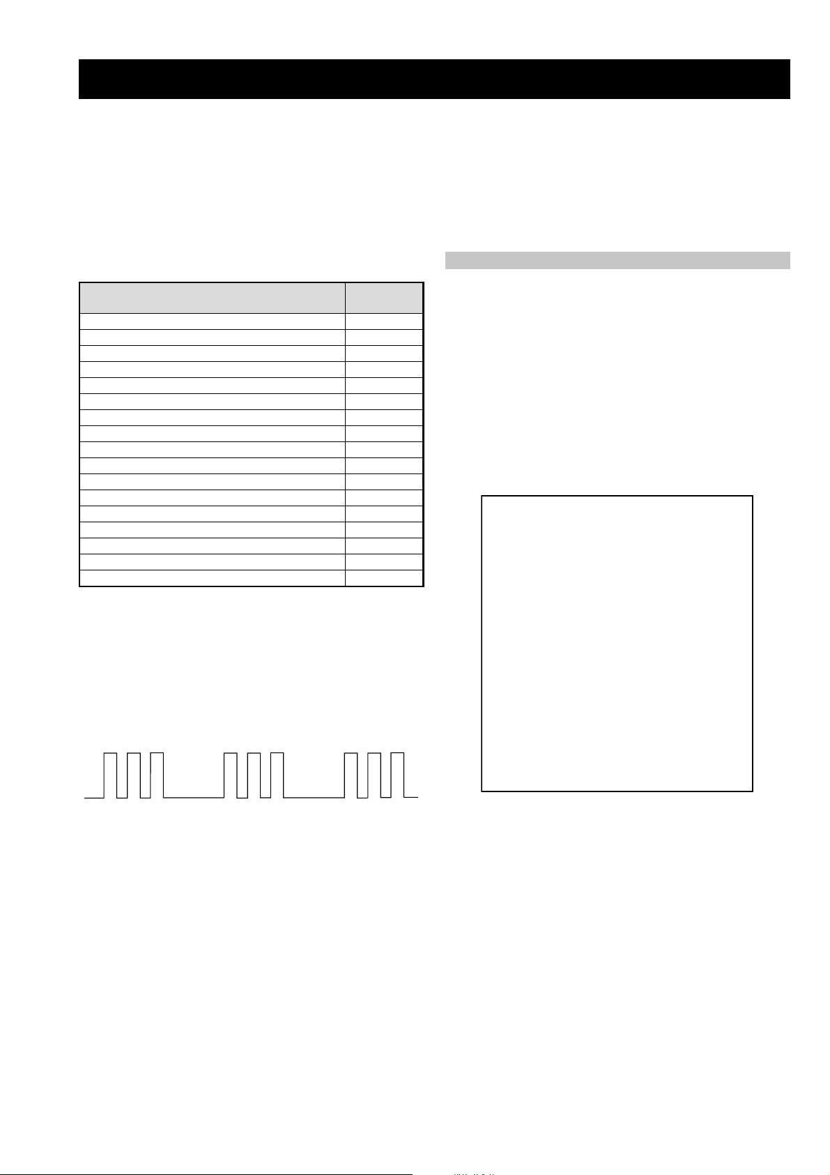
The identification of errors within the AE-6B chassis is triggered in one of two ways :- 1: Busy or 2: De vice failure to respond to IIC. In the
event of one of these situations arising the software will first try to release the bus if busy (Failure to do so will report with a continuous
flashing LED) and then communicate with each device in turn to establish if a device is f aulty . If a device is found to be faulty the rele v ant
device number will be displayed through the LED (Series of flashes which must be counted) See table 1, non fatal errors are reported using this
method.
Each time the software detects an error it is stored within the NVM. See T able 2.
Table 1
egasseMrorrE
rorreoN00
devreseR10
)noitcetorPtnerruCrevO(PCO20
noitcetorPegatloVrevO30
cnySlacitreVoN40
norewoptarorrERKI50
norewoptaegdelwonkcasubCIIonMVN70
noitcetorPlatnoziroH80
norewoptaegdelwonkcaonrenuT90
rorrErossecorPdnuoS01
devreseR11
rorrEetarnacS21
rorrECAD31
rorrEdnekcaB41
rorrEecnegrevnoCcimanyD51
rorrEPIP61
Flash Timing Example : e.g. error number 3
StBy LED
ON
OFF
ON ON
OFF
norewoptawolsenilatadro/dnakcolcsubCII60
How to enter into T able 2
DEL
edoC
1. Turn on the main power switch of the TV set.
2. Program Remote Commander for Operation in Service
Mode. [See Page 20].
3. Press ‘VIDEO’ ‘VIDEO’ > ‘MENU’ on the Remote
Commander.
4. Using the Remote Commander, Scroll to the ‘Error Menu’
item using the down arrow key, then press the right
arrow key.
5. The following table will be displayed indicating the error
count.
Table 2
UNEMRORRE
20E
30E
40E
50E
60E
70E
80E
90E
01E
11E
21E
31E
41E
51E
61E
EMITGNIKROW
SRUOH
SETUNIM
PCO
PVO
CNYSV
RKI
CII
MVN
TORPH
RENUT
PDNUOS
ETARNACS
CAD
DNEKCAB
NOCNYD
PIP
)552,0(
0
)552,0(
0
)552,0(
0
)552,0(
0
)552,0(
0
)552,0(
0
)552,0(
0
)552,0(
0
)552,0(
0
)552,0(
0
)552,0(
0
)552,0(
0
)552,0(
0
)552,0(
0
)552,0(
0
41
7
Note: T o clear the error count data press ‘80’ on the Remote
commander.
- 5 -
SECTION 1 GENERAL
OK
OK
No
Yes
automatic tuning?
Do you want to start
Auto Tuning
System: B/G
Programme: 01
Searching...
Channel: C21
This procedure could take some minutes. Please be
5 The Auto Tuning menu appears on the screen. Press the
OK button to select Yes.
6The TV starts to automatically search and store all
available broadcast channels for you.
patient and do not press any buttons, otherwise the
OK
OK
Confirm
No channel found
Please connect aerial
If no channels were found during the auto tuning
process then a new menu appears automatically on
the screen asking you to connect the aerial. Please
connect the aerial (see page 6) and press OK. The
auto tuning process will start again.
automatic tuning will not be completed.
OK
OK
Programme Sorting
Programme:
7 After all available channels are captured and stored,
the Programme Sorting menu appears automatically
MENU
01 TVE
02 TVE2
03 TV3
04 C33
05 C27
06 C58
Select channel:
Exit:
a) If you wish to keep the broadcast channels in the
on the screen enabling you to change the order in
which the channels appear on the screen.
b) If you wish to store the channels in a different order:
tuned order, go to step 8.
OK
OK
Programme Sorting
Programme:
01 TVE
02 TVE2
03 TV3
04 C33
05 C27
06 C58 05 C27
Select new position:
Exit: MENU
number with the channel (TV Broadcast) you wish
programme number position for your selected
1 Press the or button to select the programme
2 Press the or button to select the new
to rearrange, then press the button.
the order of the other channels.
3 Repeat steps b)1 and b)2 if you wish to change
channel (TV Broadcast), then press .
MENU
Your TV is now ready for use
8 Press the MENU button to remove the menu from the
screen.
First Time Operation
8
The operating instructions mentioned here are partial abstracts from the ‘Operating
Instruction Manual’. The page numbers of the ‘Operating Instruction Manual’ remain
as in the manual.
GB
OK
OK
$
i4Svenska
Norsk
English
Nederlands
Français
Italiano
i
Language
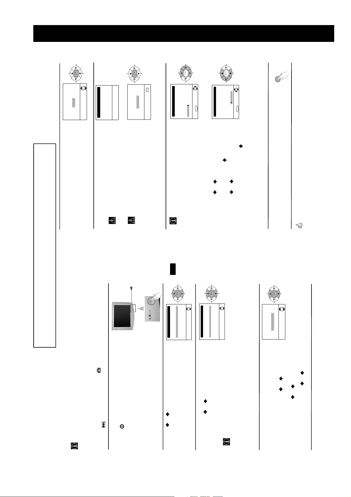
The first time you switch on your TV, a sequence of menu screens appear on the TV ena-
bling you to: 1) choose the language of the menu screen, 2) choose the country in which you
wish to operate the TV, 3) adjust the picture slant 4) search and store all available channels
(TV Broadcast) and 5) change the order in which the channels (TV Broadcast) appear on the
screen.
However, if you need to change any of these settings at a later date, you can do that by
selecting the appropriate option in the (Set Up menu) or by pressing the Auto Start Up
Button on the TV set.
50Hz)
displays automatically on the TV screen.
Press the on/off button on the TV set to turn on the TV.
The first time you press this button, a Language menu
Switching On the TV and Automatically Tuning
1 Connect the TV plug to the mains socket (220-240V AC,
2 Press the or button on the remote control to select
Select Language:
the language, then press the OK button to confirm your
selection. From now on all the menus will appear in the
selected language.
OK
OK
$
i4Sverige
Norge-Italia
Deutschland
Österreich
i
Country
Select country:
• If the country in which you want to use the TV set
screen. Press the or button to select the country in
which you will operate the TV set, then press the OK
button to confirm your selection.
3 The Country menu appears automatically on the TV
OK
OK
Adjust now
Not necessary
adjust picture rotation
If picture slants, please
country.
Cyrillic languages we recommend to select Russia
country in the case that your own country does not
appear in the list.
• In order to avoid wrong teletext characters for
does not appear in the list, select “-” instead of a
4 Because of the earth’s magnetism, the picture might slant.
necessary and press OK.
then press OK and correct any slant of the picture
between –5 and +5 by pressing or . Finally press
a) If it is not necessary, press or to select Not
The Picture Rotation menu allows you to correct the
picture slants if it is necessary.
OK to store.
b) If it is necessary, press or to select Adjust now,
7
continued...
First Time Operation
- 6 -
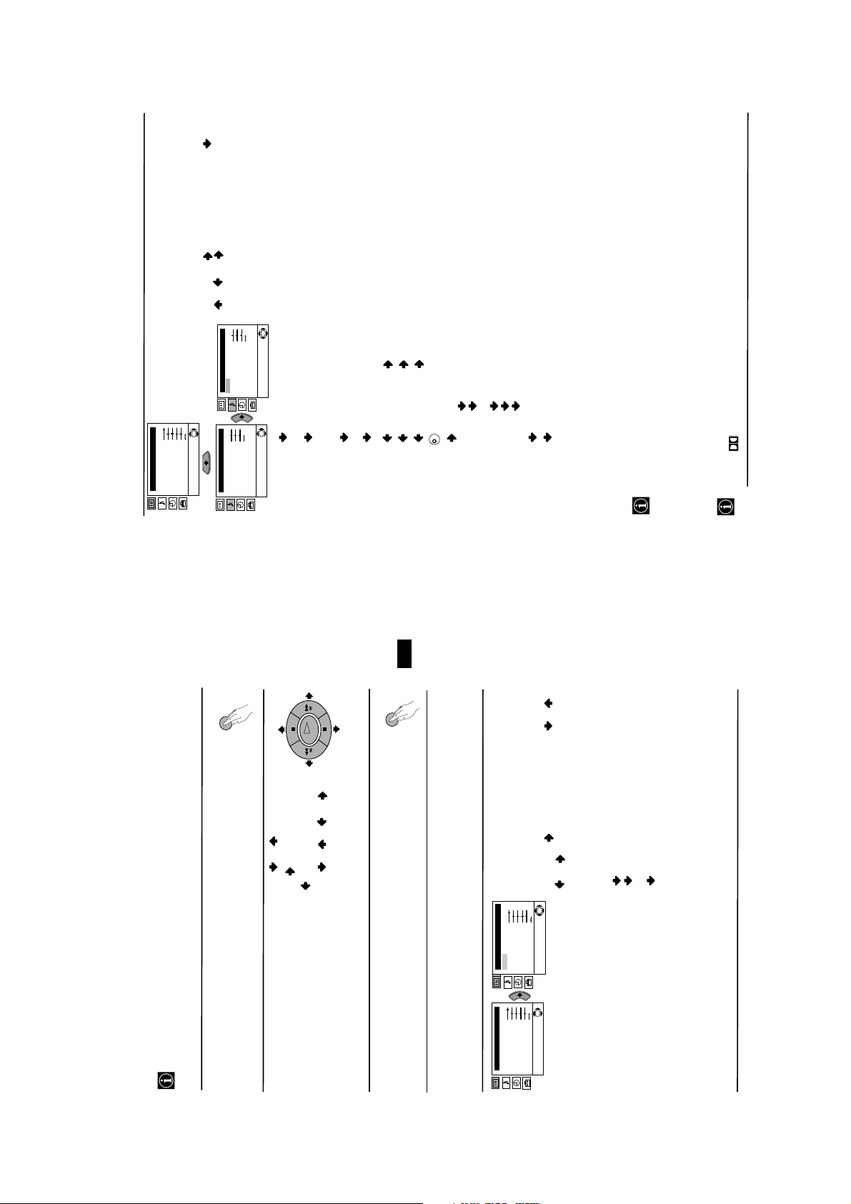
alter the sound adjustments.
To do this: after selecting the item you want to
Brightness
Colour
Sharpness
Hue
alter, press . then press repeatedly /
OK
Reset
SOUND ADJUSTMENT
The “Sound Adjustment” menu allows you to
Picture Adjustment
Mode: Personal
Contrast
Level 1 Level 2 Level 3 / Function
/ or to adjust it and finally press OK
to store the new adjustment.
OK
“BBE High Definition Sound system”*.
Sound Adjustment
Effect: Natural
Treble
Bass
Balance
Reset
Dual Sound: Mono
Auto volume: On
OK
Sound Adjustment
Effect: Natural
Treble
Bass
Balance
Reset
Dual Sound: Mono
Auto volume: On
Dynamic: “BBE High Definition Sound system”* intensifies clarity
Effect Natural: enhances clarity, detail and presence of sound by using
and presence of sound for better intelligibility and
musical realism.
Mono.
Stereo.
Mono (for mono channel if available).
A (for channel 1).
**Virtual: simulates the sound effect of Dolby Prologic surround.
B (for channel 2).
• For a bilingual broadcast:
K
Reset Resets the sound to the factory preset levels.
Dual Sound: • For a stereo broadcast:
Balance Left Right
Bass Less More
Off: flat response.
Dolby
Treble Less More
continued...
broadcast signal (e.g. in the case of advertisements).
Off: volume level of the channels will stay the same, independent of the
This TV has been designed to create the “Dolby Surround” sound effect by simulating the sound
of four speakers with two speakers, when the broadcast audio signal is Dolby Surround encoded.
The sound effect can also be improved by connecting a suitable external amplifier (for details refer
to “Connecting to external audio Equipment” on page 19).
from BBE Sound, Inc. It is covered by U.S. Patent No. 4,638,258 and No. 4,482,866. Teh word
“BBE” and BBE Symbol are trademarks of BBE Sound, Inc.
The “BBE High Definition Sound system” is manufactured by Sony Corporation under license
*
to “Off” and vice versa.
Auto Volume: On: volume level changes according to the broadcast signal.
Off.
• If you are listening to the TV through headphones, the “Effect” option will automatically switched to
• If you switch “Effect” to “Dolby Virtual”, the “Auto Volume” option will automatically be switched
**
symbol are trademarks of Dolby Laboratories.
** Manufactured under license from Dolby Laboratories. “Dolby”, “Pro Logic” and the double-D
Menu System
10
GB
MENU
Your TV uses an on-screen menu system to guide you through the operations. Use the
following buttons on the Remote Control to operate the menu system:
Introducing and Using the Menu System
1 Press the MENU button to switch the first level menu on.
OK
• To enter to the selected menu or option, press .
• To return to the last menu or option, press .
2 • To highlight the desired menu or option, press or .
• To alter settings of your selected option, press //or.
MENU
• To confirm and store your selection, press OK.
3 Press the MENU button to remove the menu from the screen.
Level 1 Level 2 Level 3 / Function
Menu Guide
or to adjust it and finally press OK to
store the new adjustment.
PICTURE ADJUSTMENT
The “Picture Adjustment” menu allows you to
alter the picture adjustments.
To do this: after selecting the item you want to
OK
Picture Adjustment
Mode: Personal
Contrast
Brightness
Colour
Sharpness
Hue
Reset
OK
Picture Adjustment
Mode: Personal
Contrast
Brightness
Colour
Sharpness
Hue
Reset
This menu also allows you to customise the
alter press , then press repeatedly / /
9
continued...
Menu System
Personal (for individual settings).
Live (for live broadcast programmes, DVD
Movie (for films).
picture mode based on the programme you are
watching:
and Digital Set Top Box receivers).
• Brightness, Colour and Sharpness can only be altered if “Personal” mode is selected.
• Hue is only available for NTSC colour signal (e.g: USA video tapes).
• Select Reset and press OK to reset the picture to the factory preset levels.
- 7 -
 Loading...