

Sony KV-29K1E Schematic
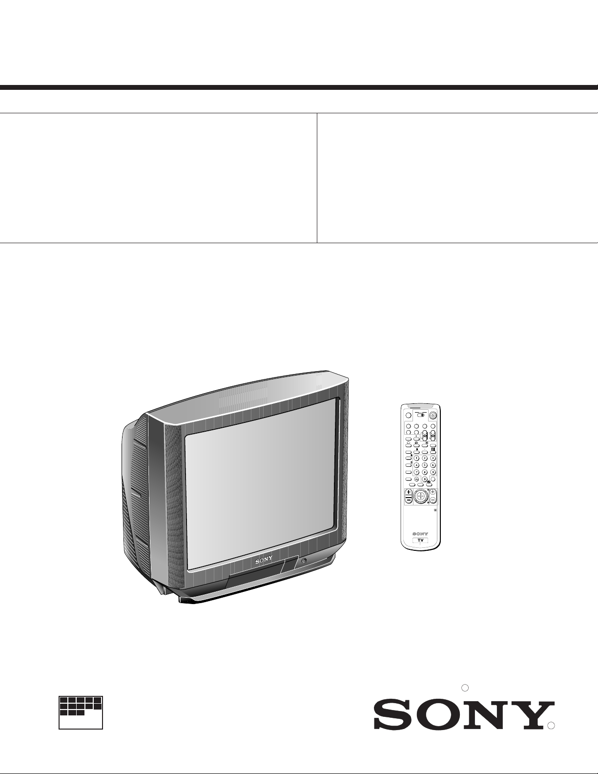
KV-29K1
SERVICE MANUAL
MODEL
KV-29K1A
KV-29K1B
KV-29K1D
KV-29K1E
RM-862
RM-862
RM-862
RM-862
DEST.COMMANDER CHASSIS NO.
Italian
French
AEP
Spanish
SCC-K43G-A
SCC-K45G-A
SCC-K41G-A
SCC-K42G-A
MODEL
KV-29K1K
KV-29K1R
KV-29K1U
AE-4
COMMANDER
RM-862
RM-862
RM-862
CHASSIS
DEST.
OIRT
Russian
UK
CHASSIS NO.
SCC-K44G-A
SCC-K44H-A
SCC-K46C-A
TV
MDP2
3VTR 1
¤
VIDEO
0
( u)
p Pr
+
CH
REC
+
˚
;
_
?
…/
Ú/;
8
;
´8x
´/´
a/Å
A
b
c
≥
MENU
¸
PROGR
RM-862
TRINITRON COLOR TV
R
MICROFILM
R
— 1 —

KV-29K1
nailatIKD,H/G/B
hcnerFI,L,K/D,H/G/B
metsySruoloCegarevoClennahCmetsySnoisiveleTLEDOMMETI
LAP96-12:FHU)C(2H-A:FHVAILATI
14S-1S:)1(VTELBAC
96E-12E:FHU21E-2E:FHVH/G/B
01U-1U,01M-1M,50S-102:)2(VTELBAC
96R-12R:FHU21R-10R:FHVK/D
06F-12F:FHU01F-20F:FHVL
21E-2E:FHVH/G/BQ-B:ELBAC
96E-12E:FHU
14S-1S:)1(VTELBAC
01U-1U,01M-1M,50S-10S:)2(VTELBAC
96-12:FHU)C(2H-A:FHVAILATI
96B-12B:FHUI
MACES,LAP
34.4/85.3CSTN
)ylnotupnioediv(
MACES,LAP
34.4/85.3CSTN
)ylnotupnioediv(
96E-12E:FHU21E-2E:FHVH/G/BLAP
01U-1U,01M-1M,50S-10S:)2(VTELBAC
96-12:FHU)C(2H-A:FHVAILATI
96B-12B:FHU02R-10R:FHVK/D
96E-12E:FHU21E-2E:FHVH/G/BLAP
01U-1U,01M-1M,50S-10S:)2(VTELBAC
96-12:FHU)C(2H-A:FHVAILATI
96B-12B:FHU02R-10R:FHVK/D
96E-12E:FHU21E-2E:FHVH/G/B
96R-12R:FHU21R-10R:FHVK/D
96E-12E:FHU21E-2E:FHVH/G/B
96R-12R:FHU21R-10R:FHVK/D
LAP
MACES,LAP
34.4/85.3CSTN
)ylnotupnioediv(
MACES,LAP
34.4/85.3CSTN
)ylnotupnioediv(
MACES,LAP
34.4/85.3CSTN
)ylnotupnioediv(
MACES,LAP
34.4/85.3CSTN
)ylnotupnioediv(
34.4/85.3CSTN
)ylnotupnioediv(
PEAK/D,H/G/B
hsinapSK/D,H/G/B
TRIOK/D,H/G/B
NAISSURK/D,H/G/B
KUI 96-12FHU
14S-1S:)1(VTELBAC
14S-1S:)1(VTELBAC
14S-1S:)1(VTELBAC
14S-1S:)1(VTELBAC
LEDOMA1K92B1K92D1K92K1K92R1K92E1K92U3F92
noitpmusnocrewoPW221W831W831W831W831W831W012
Picture Tube Super Trinitron
Approx. 72 cm (29 inches)
(Approx. 68 cm picture measured
diagonally) 100˚ deflection
Rear/Front Terminals
[REAR]
21-pin Euro connector (CENELEC standard)
- Inputs for audio and video signals
- Inputs for RGB
- Outputs of TV video and radio signals
2/ 2 21-pin Euro connector
- Inputs for audio and video signals
- Inputs for audio and video signals (selectable)
2 Audio outputs - phono jacks
SPECIFICATIONS
[FRONT]
3 Video input - phono jack
3 Audio inputs - phono jacks
3 S video input - 4 pin DIN
Headphone jack - stereo minijack
Sound output 30Wx2 (music power)
15Wx2 (RMS)
Dimensions 680X582X536mm approx.
Weight Approx. 50kg
Supplied accessories RM-862 Remote Commander (1)
R6 batteries (2)
Other features TELETEXT , Fasttext
FLOF/TOP text,
NICAM (KV-29K1B/29K1E/29K1U ony)
— 2 —
[RM-862]
Remote control system Infrared control
Power requirements 3V dc (2 batteries) R6 (size AA)
Dimensions Approx. 210x56x24 mm (w/h/d)
Weight Approx. 110g
(Not including battery)
Design and specifications are subject to change without
notice.
Model name
A1K92-VKB1K92-VKD1K92-VKE1K92-VKK1K92-VKR1K92-VKU1K92-VK
Item
retliFbmoClatigiDNONONONONONONO
noitcudeResioNlatigiDNONONONONONONO
PIPFFOFFOFFOFFOFFOFFOFFO
PIPMNONONONONONONO
erutciP&erutciPNONONONONONONO
lioCnoitatoRNONONONONONONO
draobpilCNONONONONONONO
)32eniL(9:61otuAFFOFFOFFOFFOFFOFFOFFO
TXTNONONONONONONO
FOLFNONONONONONONO
POTNONONONONONONO
teserPegaugnaLnailatIhcnerFnamreGhsinapSTRIOTRIOhsilgnE
KV-29K1
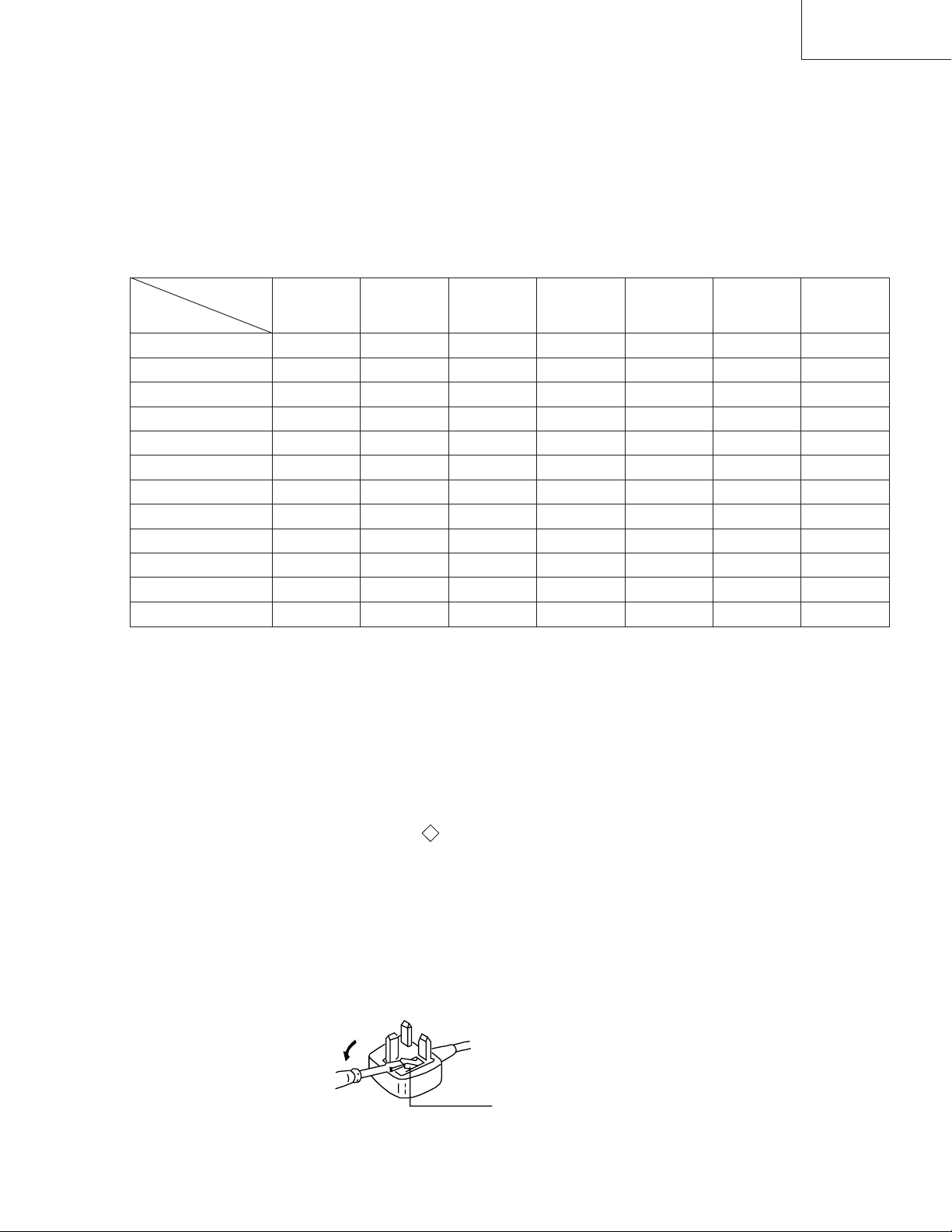
WARNING ( KV-29K1U only )
The flexible mains lead is supplied connected to a B.S. 1363 fused
plug having a fuse of 5 AMP capacity. Should the fuse need to be
replaced, use a 5 AMP FUSE approved by ASTA to BS 1362, ie
one that carries the mark.
IF THE PLUG SUPPLIED WITH THIS APPLIANCE IS NOT
SUITABLE FOR YOUR SOCKET OUTLETS IN YOUR HOME.
IT SHOULD BE CUT OFF AND AN APPROPRIATE PLUG FITTED.
THE PLUG SEVERED FROM THE MAINS LEAD MUST BE
DESTROYED AS A PLUG WITH BARED WIRES IS
DANGEROUS IF ENGAGED IN A LIVE SOCKET OUTLET.
When an alternative type of plug is used it should be fitted with a 5 AMP
FUSE, otherwise the circuit should be protected by a 5 AMP FUSE at the
distribution board.
ASA
T
How to replace the fuse.
Open the fuse compartment with the
screwdriver blade
and replace the fuse.
FUSE
— 3 —

KV-29K1
21 pin connector ( 1, 2/ 2 )
G
1
1
21
19
17
15
13
11
9
7
5
3
1
20
18
16
14
12
10
8
6
4
2
Y2/j
.oNniP 124 langiSleveLlangiS
1
2
2
2/
2
3
4
5
6
7
8
9
01
11
21
31
41
51
61
71
81
91
02
12
Connected
BtuptuooiduA
)thgiR(
BtupnioiduA
)thgiR(
AtuptuooiduA
)tfeL(
)oiduA(dnuorG
)eulB(dnuorG
AtupnioiduA
)tfeL(
tupnieulB7.0 ± evitisop,smho57,Bd3
tcelesnoitcnuF
)lortnocVA(
)neerG(dnuorG
nepO
neerG
nepO
)deR(dnuorG
)gniknalB(dnuorG
tupnideR7.0 ± evitisop,smho57,Bd3
)langisS(
tupniamorc
tupnigniknalB
)langissY(
dnuorG
)tuptuooediV(
dnuorG
)tupnioediV(
tuptuooediV
tupnioediV
tupnioediV
)langisS(Y
dnuorgnommoC
)dliehs,gulp(
Not Connected (Open) * at 20Hz - 20kHz
7.0 ± evitisop,smho57,Bd3
V1 ± ,smho57,Bd3
V1 ± ,smho57,Bd3
V1 ± ,smho57,Bd3
smrV5.0:leveldradnatS
smrV5.0:leveldradnatS
smrV5.0:leveldradnatS
smrV5.0:leveldradnatS
edomVT:)V2-0(etatswoL
smho57:ecnadepmitupnI
*smhok1nahtsseL:ecnadepmituptuO
*smhok01nahteroM:ecnadepmituptuO
*mhok1nahtsseL:ecnadepmituptuO
*mhok01nahtsseL:ecnadepmituptuO
edomtraP:)V21-5.9(etatshgiH
smhok01eroM:ecnadepmitupnI
Fn2nahtsseL:ecnaticapactupnI
)V4.0-0(etatswoL)V3-1(etatshgiH
)Bd01+3-(V3.0:cnysevitisop
)Bd01+3-(V3.0:cnysevitisop
)Bd01+3-(V3.0:cnysevitisop
.oNniPlangiSleveLlangiS
1dnuorG
2dnuorG
3tupni)langisS(YV1 ± Bd01+3-V3.0.cnySevitisop,mho57Bd3
4tupni)langisS(CV3.0 ± .cnySevitisop,mho57Bd3
— 4 —
MONO
3
L/G/S/I R/D/D/D
3
3
P

TABLE OF CONTENTS
Section Title PageSection Title Page
KV-29K1
1. GENERAL
Overview ....................................................................
Basic Operation ..........................................................
Advanced Operation ...................................................
Teletext .......................................................................
Optional Equipment ...................................................
Additional Information ...............................................
2. DISASSEMBLY
2-1. Rear Cover Removal ..................................................
2-2. Chassis Assy Removal ...............................................
2-3. Service Position ..........................................................
2-4. G Board Removal .......................................................
2-5. A Board Removal .......................................................
2-6. Picture Tube Removal ................................................
Removal and Replacement of
the Main-Bracket Bottom Paltes ................................
3. SET-UP ADJUSTMENTS
3-1. Beam Landing ............................................................
3-2. Convergence ...............................................................
3-3. Focus ..........................................................................
3-4. Screen (G2), White Balance
(Adjustment in the service mode
with remote commaner ...............................................
4. CIRCUIT ADJUSTMENTS
4-1. Electrical Adjustments................................................
4-2. Volume Electrical Adjustments..................................
4-3. Test Mode 2:...............................................................
5. DIAGRAMS
7
8
9
13
15
16
17
17
17
17
18
18
19
5-1. Block Diagram (1) ......................................................
Block Diagram (2) ......................................................
Block Diagram (3) ......................................................
Block Diagram (4) ......................................................
Block Diagram (5) ......................................................
5-2. Circuit Boards Location .............................................
5-3. Schematic Diagrams and Printed Wiring Boards .......
*A Board ....................................................................
*C Board.....................................................................
*T Board .....................................................................
*B Board.....................................................................
*G Board ....................................................................
*D Board ....................................................................
*VM Board .................................................................
5-4. Semiconductors ..........................................................
5-5. IC Blocks ....................................................................
6. EXPLODED VIEWS
20
21
23
6-1. Chassis ........................................................................
6-2. Picture Tube ...............................................................
7. ELECTRICAL PARTS LIST ...............................
23
24
28
29
31
33
35
39
41
44
49
57
61
67
75
80
85
87
90
91
92
93
SHORT CIRCUIT THE ANODE OF THE PICTURE TUBE AND THE
ANODE CAP TO THE METAL CHASSIS, CRT SHIELD, OR CARBON
PAINTED ON THE CRT, AFTER REMOVING THE ANODE.
AN ISOLATION TRANSFORMER SHOULD BE USED DURING ANY
SERVICE TO AVOID POSSIBLE SHOCK HAZARD, BECAUSE OF
LIVE CHASSIS.
THE CHASSIS OF THIS RECEIVER IS DIRECTLY CONNECTED TO
THE AC POWER LINE.
SAFETY-RELATED COMPONENT WARNING!!
COMPONENTS IDENTIFIED BY SHADING AND MARK ON THE
SCHEMATIC DIAGRAMS, EXPLODED VIEWS AND, IN THE PARTS
LIST ARE CRITICAL FOR SAFE OPERATION. REPLACE THESE
COMPONENTS WITH SONY PARTS WHOSE PART NUMBERS
APPEAR AS SHOWN IN THIS MANUAL OR IN SUPPLEMENTS
PUBLISHED BY SONY.
CAUTION
WARNING !!
!
APRES AVOIR DECONNECTE LE CAP DE L'ANODE, COURTCIRCUITER L'ANODE DU TUBE CATHODIQUE ET CELUI DE
L'ANODE DU CAP AU CHASSIS METALLIQUE DE L'APPAREIL,
OU AU COUCHE DE CARBONE PEINTE SUR LE TUBE CATHODIQUE
OU AU BLINDAGE DU TUBE CATHODIQUE.
AFIN D'EVITER TOUT RISQUE D'ELECTROCUTION PROVENANT
D'UN CHÁSSIS SOUS TENSION, UN TRANSFORMATEUR
D'ISOLEMENT DOIT ETRE UTILISÉ LORS DE TOUT DÉPANNAGE.
LE CHÁSSIS DE CE RÉCEPTEUR EST DIRECTEMENT RACCORDÉ
À L'ALIMENTATION SECTEUR.
ATTENTION AUX COMPOSANTS RELATIFS À LA
LES COMPOSANTS IDENTIFIÈS PAR UNE TRAME ET PAR UNE
MARQUE SUR LES VUES EXPLOSÉES ET LES LISTES DE
PIECES SONT D'UNE IMPORTANCE CRITIQUE PUR LA SÉCURITÉ
DU FONCTIONNEMENT. NE LES REMPLACER QUE PAR DES
COMPOSANTS SONY DONT LE NUMÉRO DE PIÉCE EST INDIQUÉ
DANS LE PRÉSENT MANUEL OU DANS DES SUPPLÉMENTS
PUBLIÉS PAR SONY.
!
ATTENTION
ATTENTION !!
SÉCURITÉ!!
— 5 —
KV-29K1
SECTION 3
SET -UP ADJUSTMENTS
• When complete readjustment is necessary or a new picture
tube is installed, carry out the following adjustments.
• Unless there are specific instructions to the contrary, carry
out these adjustment with the rated power supply.
• Unless there are specific instructions to the contrary, set the
controls and switches as follows.
Contrast............ normal
Brightness ........ normal
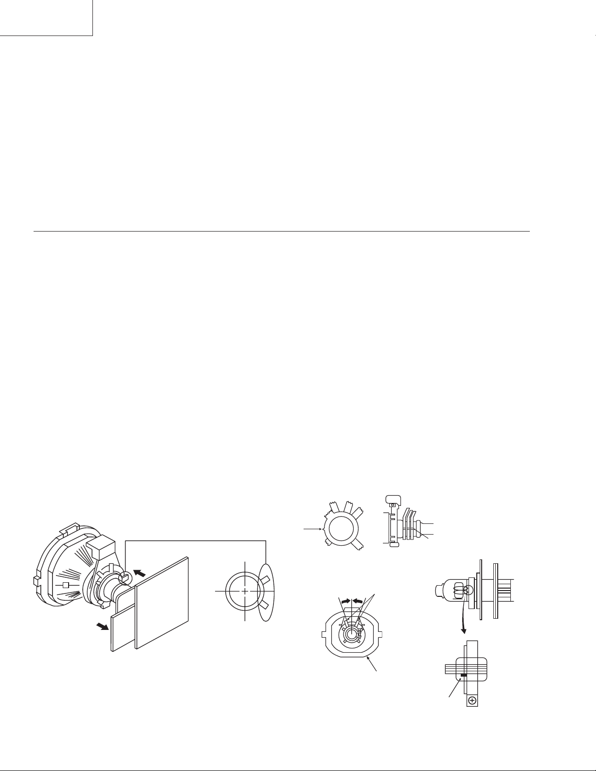
3-1. BEAM LANDING
Preparation:
1. In order to reduce the influence of geomagnetism on the set’s
picture tube face it in an easterly or westerly direction.
2. Switch on the set’s power and degauss with the degausser.
(1) Adjustment of Correction Magnet for Y-Splitting
Axis
1. Input a crosshatch signal from the pattern generator.
2. Picture control is minimum and brightness control is still
normal.
3. Position the neck assy as shown in Fig. 3-2.
4. Move the deflection yoke forward to touch the CRT and it
stands up rightly.
5. Adjust the upper pin and the lower pin symmetrically by
opening or closing the Y-splitting axis correction magnets
on the neck assy.
6. Return the deflection yoke to its original position.
• Carry out the following adjustments in this order:
3-1. Beam landing
3-2. Convergence
3-3. Focus
3-4. White balance
Note:Testing equipment required.
1. Color bar/pattern generator
2. Degausser
3. Vector scope
(2) Landing
Note: Before carrying out the following adjustments adjust the
magnets as indicated below (See Fig.3-3).
1. Input an all-white signal from the pattern generator.
Maximize the picture setting and adjust the brightness setting.
2. Rough-adjust the focus and horizontal convergence.
3. Loosen the deflection yoke screws, align the purity adjustment
knob to the central position. (See Fig. 3-1)
4. Switch from the all-white pattern to an all-green pattern.
5. Move the deflection yoke backwards and adjust with the
purity magnet so that the green is at the center and it aligns
symmetrically. (See Fig. 3-4)
6. Move the deflection yoke forward and adjust so that entire
screen becomes green.
7. Switch the raster signal to red, then to blue and verify the
landing condition.
8. When the position of the deflection yoke has been
determined, fasten the deflection yoke with the screw.
9. If the beam does not land correctly in all the corners, use
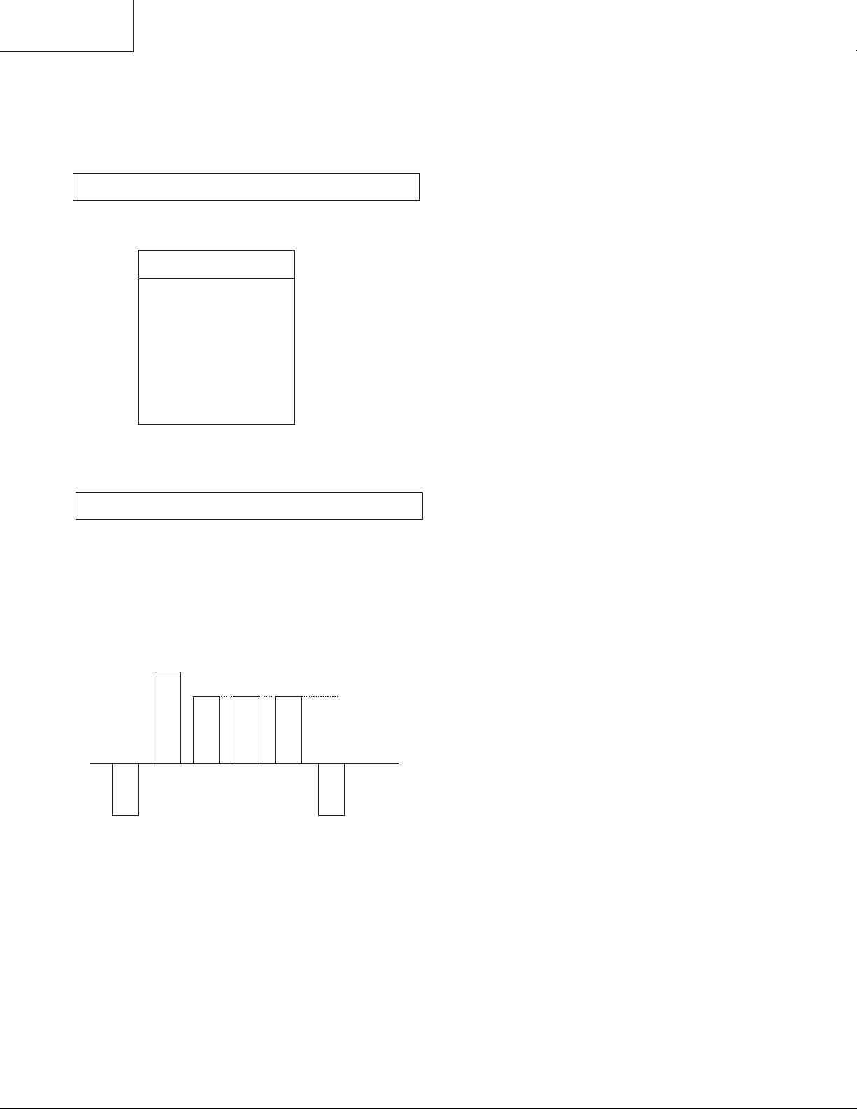
magnets to correct it. (See Fig. 3-5)
Y-splitting axis correction magnet
— 20 —
Purity Adjustment
Purity
Deflection yoke
Fig.3-1
Align the bottom edge of the neck
assy with the G3 hole center.
Fig.3-3
Align Pips
on each
magnet
Neck assy
Fig.3-2
Green
GRN
Fig.3-4
RED
Red
Blue
BLU
KV-29K1
Center dot
Purity control corrects
this area.
Deflection yoke positioning
corrects these areas
Fig.3-5
Disk magnets or
rotatable disk
magnets correct
these areas (a-d).
H.STAT
convergence
control
RV3701
Screen (G2)
Magnete statico verticale
V.STAT
C Board
RV3702 (H.STAT)
H.STAT convergence
• If the horizontal dots are unable to coincide with the
variable range of the H.STAT convergence, adjust together
with the V.STAT convergence while tracking.
(Adjust the convergence by tilting the V.STAT convergence
or by opening or closing the V.STAT convergence.)
(Open)
(Close)
3-2. CONVERGENCE
(1) Screen center convergence
(Static convergence)
1. Input a dot signal from the pattern generator. Normalize the
picture setting.
2. (Moving horizontally), adjust the H.STAT control so that
the horizontal red, green and blue dots coincide at the
center of screen.
3. (Moving vertically), adjust the V.STAT magnet so that the
vertical red, green and blue points coincide at the center of
screen.
— 21 —
4. Movement of the red, green and blue dots by tilting the
V.STAT magnet and by opening or closing the V.STAT
magnet.
1 By opening or closing the V.STAT magnet, the red, green
and blue points move as shown below
B
G
R
B
G
R
2By rotating the V. STAT magnet counterclockwise, the
red, green and blue dots move as shown below.
B
GR

KV-29K1
3By rotating the V.STAT magnet clockwise, the red, green
and blue dots move as shown below.
B
GR
4By opening or closing the V.STAT magnet, the red, green and
blue dots move as shown below.
R
G
B
G
B
R
• If the blue dot does not coincide with the red and green points,
correct the points by using the BMC (Hexapole) magnet.
5Correction for HMC (horizontal mis-convergence) and VMC
(vertical mis-convergence) by using the BMC (Hexapole)
magnet.
1HMC correction by BMC (Hexapole) magnet and movement
of the electronic beam.
HMC correction(A) HMC correction(B)
A < B
RG B
A > B
RGB
Layout of each control
Purity magnet
BMC (Hexapole) magnet
V.STAT convergence magnet
Y-splitting axis correction magnet
Fig.3-5
2. If you are unable to adjust the corner convergence properly,
correct them with the use of permalloys.
a
a—d: angoli dello
a-d: screen-corner
schermo non in
convergence defect
convergenza.
c
c
b
d
d
A = B
RG B
A = B
RG B
2VMC correction by BMC (Hexapole) magnet and movement
of the electronic beam.
VMC correction(A) VMC correction(B)
C < D
C
D
C = D C > D C = D
R
G
B
R
C
G
D
B
R
G
B
R
G
B
— 22 —
b
Permalloy Assy
X-4387-214-1
Convergence adjustment with permalloy
a
d
c

KV-29K1
3-3. Focus
1. Receive a television broadcast signal.
2. Normalize the picture setting.
3. Adjust the focus control on the flyback transformer for the
best focus at the center of the screen.
Bring only the center area of the screen into focus,
the magenta-ring appears on the screen. In this case, adjust
the focus to optimize the screen uniformly.
FOCUS
Video Proc. TDA4780
oNmetImetitnemtsujdAtnuomAataD
1TRBLORTNOCRESU
2LOCLORTNOCRESU
3CIPLORTNOCRESU
4EUHLORTNOCRESU
5NIAGR04
6NIAGGjdA
7NIAGBjdA
8FERLVLR13
9FERLVLGjdA
01FERLVLBjdA
11TIMILVRDKAEP55
21AMMAG13
31VEL2=FFOVEL3=NOPCSFFO
41YALEDFFO
3-4. Screen (G2), White balance
(Adjustment in the service mode with
remote commander)
G2 adjustment (RV3701)
1. Input a dot signal from the pattern generator.
2. Set the Picture, Brightness and Colour to minimum.
3. Apply 170V DC from an external power supply to the
R, G and B cathodes of the CRT.
4. While watching the picture, adjust the G2 control
RV3701 [ SCREEN ] on the C board to the point just
before the return lines disappear.
White balance adjustment
1. Receive an all-white signal.
2. Enter into the Service Mode by pressing ' TEST ',
' TEST ' and ' MENU' on the Service Commander.
3. Select ' VIDEO PROC. ' from the on screen menu display
and press OK .
4. The ' VIDEO PROC TDA4780' menu will appear on the
screen.
5. Set picture to MAX.
6. Set the ' R GAIN ' to 25.
7. Adjust the ' G GAIN ' and ' B GAIN ' so that the white
balance becomes optimum.
8. Press the OK button to write the data for each item.
9. Set picture to MIN.
10. Set the ' R LVL REF ' to 31.
11. Adjust ' G LVL REF ', and ' B LVL REF '
with the left and right buttons so that the white balance
becomes optimum.
12. Press the OK button to write the data for each item.
— 23 —

KV-29K1
SECTION 4
CIRCUIT ADJUSTMENTS
4-1. ELECTRICAL ADJUSTMENTS
Service adjustment to this model can be performed with the supplied
remote commander, RM-862.
HOW TO ENTER INTO SERVICE MODE
1. Turn on the main power switch of the set while pressing the
PROG + (plus) and PROG
- (minus) buttons on the front panel.
++
VOL PROG
--
Headphone
jack
2. “TT” will appear on the upper right corner of the screen.
3. Press " MENU " on the commander to get the service menu on
screen.
AV3
Input jacks
AV INPUT
oNmetImetitnemtsujdAtnuomAataD
1TRBLORTNOCRESU
2LOCLORTNOCRESU
3CIPLORTNOCRESU
4EUHLORTNOCRESU
5NIAGR04
6NIAGGjdA
7NIAGBjdA
8FERLVLR13
9FERLVLGjdA
01FERLVLBjdA
11TIMILVRDKAEP55
21AMMAG13
31VEL2=FFOVEL3=NOPCSFFO
41YALEDFFO
51FFUBATADFFO
61XIRTAMCSTNFFO
71VTDHFFO
SECIVEDSECIVED
SECIVEDSECIVED
SECIVED
VTtinI
tsujdAbuS
corPoediV
niaMceDloC
tnoC.tcelfeD
buSceDloC
xoBerutaeF
lA
AD
PIPelgniS
dnuoS
ted32eniL
edisotuA&rednopsimuL,piP
0874ADT
4419ADT
1639ADS
3419ADT
456C78S
0719ADT
0829ADS
8829ADS
4. Push the joystick up (green) or down (blue) on the remote
commander to select the adjustment item.
5. Press the center button to proceed to the next menu.
6. If the adjustment item is 'Video Proc.', push the down button to
move to 'Video Proc.'.
7. The Menu as indicated in Fig 4-3 will appear on the screen.
8. Move the joystick up or down to move to the adjustment item and
press the center (OK) button.
9. Change the data in order to comply with each standard.
81LBSFFFO
91FFOTUCOTUANO
02SID2WSFFFO
122WSFFFO
22SID1WSFFFO
321WSFFFO
42KCALBTPADANO
52V1HGIHYFFO
622DOMFFO
72HCTERTSEULB
82TUOMVFFO
92SBAVRDKAEPNO
03TIMILKAEPTSNCEMITFFO
*
Fig. 4-3 * Switch OFF for White balance Adj and Switch ON for
Shipping Condition
— 24 —
SDA9361 (DEFLECT. CONT.)
KV-29K1
oNmetImetitnemtsujdAtnuomAataD
1eziSVjdA
2errtneCVjdA
3ytiraeniLVjdA
4noitcerroCSjdA
5eziSHjdA
6pmAniPjdA
7noitcerroCrenroCpUjdA
8noitcerroCrenroCwoLjdA
9woBVjdA
01esahPniPjdA
11elgnAVjdA
21EDHNO
31RV0
41LBARNO
51siDklBFFO
61qrFeniLx2HF2NO
oNmetImetitnemtsujdAtnuomAataD
92A/D0
03emitklBV82
13emitklBH73
23nacSVtratS0
33esahpklBH16
430htdiwnacSV0
531htdiwnacSV0
63dnaBdrauG0
73nacsdertratS0
83sdleifrebmuN1
93ecalretnInoNINFFO
04deResioNcnysVRNNO
14LBVhtiwCSSNO
24dleif/senilniM0
34dleif/senilxaM0
44pmocTHECFA0
71edoMybdnatSFFO
81lacitreVNO
91tceleSklBESBFFO
02nacStratSESSFFO
12nacSdeRtratSESRSFFO
22draoBdrauGEBGFFO
32elbatemitnacSETSFFO
42noitpadAfleSASNNO
52pmocTHEV
62pmocTHEH
72ertneCH
82tratSMWP
54qerFLLP6
64RCVNO
74edoMneGFFO
84DIWSHNO
94esahpHtnIjdA
05htdiwMWP0
15RCVysioNFFO
25pizlliKFFO
011"52
57"92
001"52
53"92
23
35dr3ctFFO
45ffo4pagdnaBFFO
55ffopagdnaBFFO
65pagdnaB0
0
— 25 —

KV-29K1
TDA4780 (VIDEO PROC.)
oNmetImetitnemtsujdAtnuomAataD
1TRBLORTNOCRESU
2LOCLORTNOCRESU
3CIPLORTNOCRESU
4EUHLORTNOCRESU
5NIAGR04
6NIAGGjdA
7NIAGBjdA
8FERLVLR13
9FERLVLGjdA
01FERLVLBjdA
11TIMILVRDKAEP55
21AMMAG13
31VEL2=FFOVEL3=NOPCSFFO
41YALEDFFO
51FFUBATADFFO
61XIRTAMCSTNFFO
71VTDHFFO
81LBSFFFO
91FFOTUCOTUANO
02SID2WSFFFO
122WSFFFO
22SID1WSFFFO
321WSFFFO
42KCALBTPADANO
52V1HGIHYFFO
622DOMFFO
72HCTERTSEULB
82TUOMVFFO
92SBAVRDKAEPNO
03TIMILKAEPTSNCEMITFFO
*
* Switch OFF for White balance Adj and Switch ON for Shipping
Condition
— 26 —

KV-29K1
DEFLECTION SYSTEM ADJUSTMENT
V SIZE
1. Enter into the service mode and select 'Deflect cont.'.The
'Deflect cont. SDA9361' adjustment menu will be displayed.
2. Select and adjust each item in order to get an optimum image.
oNmetImetitnemtsujdAtnuomAataD
1eziSVjdA
2errtneCVjdA
3ytiraeniLVjdA
4noitcerroCSjdA
5eziSHjdA
6pmAniPjdA
7noitcerroCrenroCpUjdA
8noitcerroCrenroCwoLjdA
9woBVjdA
01esahPniPjdA
11elgnAVjdA
21EDHNO
31RV0
V POS
V LIN
H SIZE
H PIN CUSH
H TILT
H UP COR
41LBARNO
51siDklBFFO
61qrFeniLx2HF2NO
71edoMybdnatSFFO
81lacitreVNO
91tceleSklBESBFFO
02nacStratSESSFFO
12nacSdeRtratSESRSFFO
22draoBdrauGEBGFFO
32elbatemitnacSETSFFO
42noitpadAfleSASNNO
52pmocTHEV
62pmocTHEH
72ertneCH
82tratSMWP
H LOWER COR
AFC V BOW
AFC V ANGLE
H POS
011"52
57"92
001"52
53"92
23
0
— 27 —
KV-29K1
4-2. VOLUME ELECTRICAL ADJUSTMENTS
Sub Brightness Adjustment
1. Enter Service Mode (Device Menu).
2. Select 'SUB ADJUST MENU'.
tnemtsujdabuS
erutciPbuS
ruoloCbuS
ssenthgirBbuS
retneC3/4
retneC-HPAP
tesffO-EWHPAP
SOP-HtxeT/uneM
tesffOBGRTAP
niaGBGRTAP
wodniWgnimarFartxE
3. Adjust the value according to the following advice.
Sub Color Adjustment
1. Input a PAL color bar signal.
2. Connect an oscilloscope to CN3703.
3. Enter into 'SERVICE MODE'.
4. Choose 'SUB ADJUST'.
5. Enter into Sub Color mode.
6. Adjust data so that the right sides of the waveforms are of equal
height.
SAME LEVEL
— 28 —

13devreseR
23devreseR
33tsetPIPitluM
43tsetedomotohP
53FFO/NOgnitumoediV
63devreseR
73devreseR
83)sledom3:4roftoN(tsetedoMneercS
93elbatmargorpteseR
04deteledsiyrtnehtneT
14muminimerutciP
24noybloD
34ffoybloD
44.nimciP+.jdassenthgirBbuSotsseccatceriD
54edomtcetorpotMVNteS
64edomgniteserplennahcRI
74)DSOo/w(noitcelesecruosenohpdaeH
84)DSOo/w(tnemtsujdaOGAotsseccatceriD
94
ydaerlastcetedetybsihT(etybtsetMVNehtesarE
hctiws,noitcnufsihtgnitcelesretfA.)s'MVNderots
orcimehtybteserpeblliwMVNehT.nodnaffoVT
05deteledsiyrtnehtneT
15tsetebortS
25)ksatwohS(ylnoesulanretnI
35ffo/nolA/rednopsuonimuL
45)DSOo/w(MVotsseccatceriD
55)L.sySylno('ssapwoL`lortnocrecilSXTM
65'noitasnepmocoN`lortnocrecilSXTM
75NOunemecivrestxetageM
85wodniwedocgnimarfllamsXTM
95wodniwedocgnimarfediwXTM
06deteledsiyrtnehtneT
16sevlavtluafedYBLODteS
26elbasidICA
36elbaneICA
KV-29K1
4-3. TEST MODE 2:
Is available by pressing the Test button twice, OSD “TT” appears. The functions described below are available by pressing the two numbers.
To release the Test Mode 2, press `0' twice, or switch the TV into Standby Mode.
00ffo2edoMtseThctiwS
10muminimoterutcip&ruolocmuminimteS
20)DSOo/w(noitcuderesioNotsseccatceriD
30%03otemulovteS
40)elbaliava99.rPniylnO('edoMecivreS`
50)elbaliava99.rPniylnO('edoMnoitcudorP`
60%08otemulovteS
70
80
90
01deteledsiyrtnehtneT
11)DSOo/w(ecnalabotsseccatceriD
21)DSOo/w(EUHotsseccatceriD
31unemnoitarugifnoC
41noitamrofninoitcudorPfoyalpsiD
51
61atadyromeMrewoPtsaLlautcaevaS
71secruosVAroflebalteserP
81FFO/NOtxeT
91%05otemulovteS
02deteledsiyrtnehtneT
120>-4+>-4-:tsetliocnoitatoR
22yalpsidrotinomrorrednaremitgnitarepO
32)DSOo/w(ssenthgirbbusotsseccatceriD
42)DSOo/w(ruolocbusotsseccatceriD
52yalpsidunemsutatS
62eporuEtseW:noitcelestesretcaractxeT
72eporuEtsaE:noitcelestesretcaractxeT
82hsilgnEKU-eporuE.W:noitcelestesretcaractxeT
92hsikruTeporuEtseW:noitcelestesretcaractxeT
03deteledsiyrtnehtneT
).xam
)nodehctiwssi
seulavdesu
ssenthgirb&erutcip;.nim.loV(noitidnocgnigA
eudTESEReraseulavgolanA(noitidnocgnippihS
)ffoedomTT,detcelessi1.gorP.gnittesyrotcafot
tesnehwsraeppaunemegaugnaL(teseregaugnaL
,emuloVsdaer,MVNmorfgnittesyrotcafdaeR
,EUH,tsartnoC,ssenthgirB,ssaB,elberT,ecnalaB
lautcaehtotMORmorfseulavruoloC,ssenprahS
— 29 —
KV-29K1
46sdnammocevalSC2IllateseR
56MVNnisedocrorrederotsteseR
66relortnocbusdnarelortnoclacol+LAProfteseR
76)DSOo/w(emulovenohpdaeHotsseccatceriD
86nosrorreerongI
96ffosrorreerongI
07deteledsiyrtnehtneT
17FFO/NOnoitatorerutciP
27ediwedomYBLOD
37desaercedpetsenoleveltxetBGRtxetageM
47desaercnipetsenoleveltxetBGRtxetageM
57DIkrowtenrofdevreseR
671639ADSrofevlavtluafeD
770829ADSrofeulavtluafeD
87+LAProfseulavtluafeD
974419ADTrofeulavtluafeD
08deteledsiyrtnehtneT
280719ADTrofeulavtluafeD
385817AASrofeulavtluafeD
480874ADTrofeulavtluafeD
584419ADTrofeulavtluafeD
683419ADTrofeulavtluafeD
788829ADSrofeulavtluafeD
88tsae/aissuRtesretcarahctxeT
98tsew/aissuRtesretcarahctxeT
09deteledsiyrtnehtneT
19lamronedomYBLOD
29elbasidPTI
39elbanePTI
49'tfel`ecneuqesesioN
59'ertnec`ecneuqesesioN
69'thgir`ecneuqesesioN
79'dnuorrus`ecneuqesesioN
89'ffo`edomdnuorruS
18xobserutaeFrofseulavtluafeD
99'motnahp`edomYBLOD
— 30 —
 Loading...