

Sony kv28hx15b schematic
SERVICE MANUAL
FE-2
CHASSIS
MODEL
KV-28HX15B
KV-28HX15E
KV-28HX15U
COMMANDER DEST CHASSIS NO.
RM-947 FR SCC-Q54X-A
RM-947 ESP SCC-Q53Y-A
RM-947 UK SCC-R42A-A
MODEL
KV-32HX15B
KV-32HX15E
KV-32HX15U
COMMANDER DEST CHASSIS NO.
RM-947 FR SCC-Q54W-A
RM-947 ESP SCC-Q53X-A
RM-947 UK SCC-Q52Y-A
KV-28/32HX15
- 1 -
RM-947

TABLE OF CONTENTS
Section Title Pag e Section Title Pag e
Caution .................... 3
Specifications .................... 4
Connectors .................... 5
Self Diagnostic Software .................... 6
1. GENERAL
Switching on the TV and Automatically
Tuning in channels .................... 7
Introducing and Using the menu
system .................... 8
Menu Guide .................... 8
Teletext .................... 10
Fastext .................... 10
Connecting Optional Equipment ................... 11
Using Optional Equipment ................... 11
Lifting the TV set ............. 11
Specifications .................... 12
Troubleshooting .................... 12
2. DISASSEMBLY
2-1. Rear Cover Removal .................... 13
2-2. Chassis Removal and Refitting .................... 13
2-3. A Board Removal [Step 1] .................... 14
2-4. A Board Removal [Step 2] .................... 14
2-5. F3 Board Removal .................... 14
2-6. Service Position .................... 14
2-7. Picture Tube Removal .................... 15
Bottom Plates .................... 16
5. DIAGRAMS
5-1. Block Diagrams (1) .................... 24
Block Diagrams (2) .................... 25
Block Diagrams (3) .................... 26
5-2. Circuit Board Location .................... 27
5-3. Schematic Diagrams and
Printed Wiring Boards .................... 27
* A Board PWB .................... 28
* A Board Schematic .................... 29
* H6 Board PWB .................... 34
* H6 Board Schematic .................... 33
* F5 Board PWB .................... 34
* F5 Board Schematic .................... 33
* F3 Board PWB .................... 34
* F3 Board Schematic .................... 33
* C Board PWB .................... 36
* C Board Schematic .................... 35
* D2 Board PWB .................... 36
* D2 Board Schematic .................... 35
* VM Board PWB .................... 36
* VM Board Schematic .................... 37
5-4. Semiconductors .................... 38
5-5. IC Blocks .................... 40
6. EXPLODED VIEWS
6-1. Chassis .................... 41
6-2. Picture Tube .................... 42
3. SET-UP ADJUSTMENTS
3-1. Beam Landing .................... 17
3-2. Convergence .................... 18
3-3. Focus Adjustment .................... 20
3-4. Screen (G2), White Balance .................... 20
4. CIRCUIT ADJUSTMENTS
4-1. Electrical Adjustments .................... 21
4-2. Test Mode 2 .................... 23
CAUTION
SHORT CIRCUIT THE ANODE OF THE PICTURE TUBE AND THE
ANODE CAP TO THE METAL CHASSIS, CRT SHIELD, OR THE
CARBON PAINTED ON THE CRT, AFTER REMOVAL OF THE
ANODE CAP.
WARNING !!
AN ISOLATION TRANSFORMER SHOULD BE USED DURING
ANY SERVICE WORK TO AVOID POSSIBLE SHOCK HAZARD
DUE TO LIVE CHASSIS, THE CHASSIS OF THIS RECEIVER IS
DIRECTLY CONNECTED TO THE POWER LINE.
SAFETY-RELATED COMPONENT WARNING !!
COMPONENTS IDENTIFIED BY SHADING AND MARKED
THE SCHEMATIC DIAGRAMS, EXPLODED VIEWS AND IN THE
PARTS LIST ARE CRITICAL FOR SAFE OPERATION. REPLACE
THESE COMPONENTS WITH SONY PARTS WHOSE PART
NUMBERS APPEAR AS SHOWN IN THIS MANUAL OR IN
SUPPLEMENTS PUBLISHED BY SONY.
ON
7. ELECTRICAL PARTS LIST .................... 43
ATTENTION
APRES AVOIR DECONNECTE LE CAP DE’LANODE,
COURT-CIRCUITER L’ANODE DU TUBE CATHODIQUE ET
CELUI DE L’ANODE DU CAP AU CHASSIS METALLIQUE DE
L’APPAREIL, OU AU COUCHE DE CARBONE PEINTE SUR LE
TUBE CATHODIQUE OU AU BLINDAGE DU TUBE
CATHODIQUE.
ATTENTION !!
AFIN D’EVITER TOUT RISQUE D’ELECTROCUTION
PROVENANT D’UN CHÁSSIS SOUS TENTION, UN
TRANSFORMATEUR D’ISOLEMENT DOIT ETRE UTILISÈ LORS
DE TOUT DÈPANNAGE LE CHÁSSIS DE CE RÈCEPTEUR EST
DIRECTMENT RACCORDÈ Á L’ALIMENTATION SECTEUR.
ATTENTION AUX COMPOSANTS RELATIFS Á
LES COMPOSANTS IDENTIFIÈS PAR UNE TRAME ET PAR UNE
MARQUE
EXPLOSÈES ET LES LISTES DE PIECES SONT D’UNE IMPOR-
TANCE CRITIQUE POUR LA SÈCURITÈ DU FONCTIONNEMENT,
NE LES REMPLACER QUE PAR DES COMPSANTS SONY DONT
LE NUMÈRO DE PIÈCE EST INDIQUÈ DANS LE PRÈSENT
MANUEL OU DANS DES SUPPLÈMENTS PUBLIÈS PAR SONY.
SUR LES SCHÈMAS DE PRINCIPE, LES VUES
LA SECURITÈ!!
- 2 -
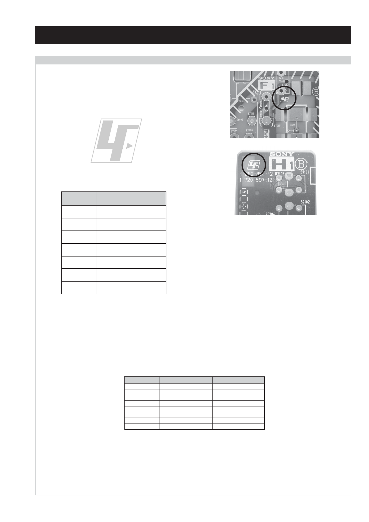
CAUTION
Lead Free Soldered Boards
The circuit boards listed below [Table 1] used in these models may
have been processed using Lead Free Solder. The boards are
identified by the LF logo located close to the board designation e.g.
F1, H1 etc [ see examples ]. The servicing of these boards requires
special precautions to be taken as outlined below.
Table 1
draoB noitcnuF
AoiduA,oediV,noitcelfeD,ylppuSrewoP
example 1
example 2
CtuOB,G,R
2DnoitcelfeDedoMtramS
3FsretliFeniL,esuF,egrahcsiDgninthgiL
5FSCRIS,DEL,tupnICA
6HonohPdnaSHVS,enohpdaeH
MVnoitaludoMyticoleV
It is strongly recommended to use Lead Free Solder material in order to guarantee optimal quality of new solder joints. Lead Free Solder is
available under the following part numbers :
rebmuntraP retemaiD skrameR
91-500-046-7mm3.0gK52.0
02-500-046-7mm4.0gK05.0
12-500-046-7mm5.0gK05.0
22-500-046-7mm6.0gK52.0
32-500-046-7mm8.0gK00.1
42-500-046-7mm0.1gK00.1
52-500-046-7mm2.1gK00.1
62-500-046-7mm6.1gK00.1
Due to the higher melting point of Lead Free Solder the soldering iron tip temperature needs to be set to 370 degrees centigrade. This requires
soldering equipment capable of accurate temperature control coupled with a good heat recovery characteristics.
For more information on the use of Lead Free Solder, please refer to http://www.sony-training.com
- 3 -
METI
LEDOM
BL,I,K/D,H/G/B
EK/D,H/G/B
UI oeretSMACIN96B-12B:FHU
ebuTerutciP
oruEnip-12:1
rotcennoc
)dradnatsCELENEC(
oruEnip-12:2
rotcennoc
skcaJonohPoiduArofelbairavsrotcennoCtuptuO
kcajenohpdaeHkcajinimoerets
stupnioiduAskcajonohp
stupnioediVskcajonohp
tupnioediVSNIDnip4
metsySnoisiveleT metsySoeretS egarevoClennahC metsySroloC
MACIN/NAMREG
oeretS
MACIN/NAMREG
oeretS
nortinirTDFyalpsiDtalF
]RAER[slanimreTtuptuO/tupnI snoitacificepSlareneG
.slangisoediVdnaoiduArofstupnI
.BGRrofstupnI
.slangisoediVdnaoiduArofstupnI
.oediVSrofstupnI
)elbatceles(
slangiS
]TNORF[slanimreTtuptuO/tupnI lortnoCderarfnI:metsySlortnoCetomeR
Q-B,01F-20F,30S-10S,21R-1R,21E-2E:FHV
02S-10S:VTELBAC
14S-12S:REPYH
30S-10S,21R-1R,21E-2E:FHV
96R-12R,96E-12E:FHU
02S-10S:VTELBAC
14S-12S:REPYH
tuptuodnuoS
)51XH82-VK()sehcni82(mc17xorppA
)51XH23-VK()sehcni23(mc28xorppA
.slangisoiduAdnaoediVVTfostuptuO
snoisnemiD
.slangisoiduAdnaoediVVTfostuptuO
thgieW
rekaepstfeLdnathgiR)SMR(W7x2)rewoPcisuM(W41x2
stnemeriuqeRrewoPV042-022
noitpmusnoCrewoP
seirosseccAdeilppuS
serutaeFrehtO
stnemeriuqerrewoP
96R-12R,96B-12B,96F-12F,96E-12E:FHU
)51XH82-VK(W27
)51XH23-VK(W57
cdV3
)AAezis(6R
.ecitontuohtiwegnahcottcejbuserasnoitacificepsdnangiseD
MACES,LAP
85.3CSTN,34.4CSTN
)NIOEDIV(
MACES,LAP
85.3CSTN,34.4CSTN
)NIOEDIV(
MACES,LAP
85.3CSTN,34.4CSTN
)NIOEDIV(
)51XH82-VK(mm845x715x488xorppA
)51XH23-VK(mm275x265x339xorppA
)51XH82-VK(gk5.44xorppA
)51XH23-VK(gk0.06xorppA
)1(rednammoCetomeR749-MR
)2(yrettab6RdetangisedCEI
,txeteleT,kniltramS,remiTpeelS
noitcetedotuametsysVT
noitangisedCEIseirettab2
metI
emaNledoM
bmoClaPFFOFFOFFO
PIPFFOFFOFFO
ytiroirPBGRNONONO
xoBrefooWFFOFFOFFO
1tracSNONONO
2tracSNONONO
3tracSFFOFFOFFO
)3(nitnorFNONONO
4tracSFFOFFOFFO
rotcejorPFFOFFOFFO
G/BmroNNONOFFO
ImroNNOFFONO
K/DmroNNONOFFO
SUAmroNFFOFFOFFO
LmroNNOFFOFFO
TASmroNFFOFFOFFO
MmroNFFOFFOFFO
txeteleTNONONO
oeretSmaciNNONONO
B51XH82-VK
~
B51XH23-VK
E51XH82-VK
~
E51XH23-VK
U51XH82-VK
~
U51XH23-VK
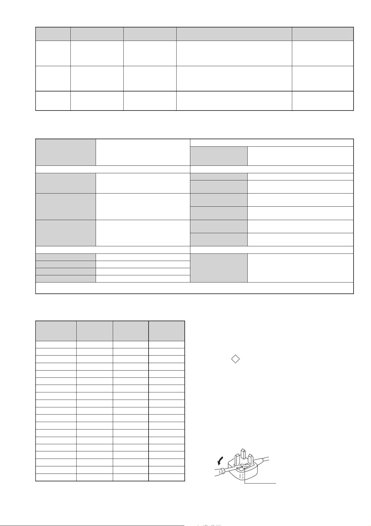
WARNING (UK Models only)
The flexible mains lead is supplied connected to a B.S. 1363 fused
plug having a fuse of 5 AMP rating. Should the fuse need to be
replaced, use a 5AMP FUSE approved by ASTA to BS 1362, ie one
ASA
that carries the
IF THE PLUG SUPPLIED WITH THIS APPLIANCE IS NOT SUITABLE FOR THE OUTLET SOCKETS IN YOUR HOME, IT SHOULD
BE CUT OFF AND AN APPROPRIATE PLUG FITTED. THE PLUG
SEVERED FROM THE MAINS LEAD MUST BE DESTROYED AS A
PLUG WITH BARED WIRES IS DANGEROUS IF ENGAGED IN A
LIVE SOCKET.
T
mark.
When an alternative type of plug is used, it should be fitted with a
5 AMP FUSE, otherwise the circuit should be protected by a 5AMP
FUSE at the distribution board.
How to replace the fuse.
Open the fuse compartment with
a screwdriver blade and replace
the fuse.
FUSE
- 4 -
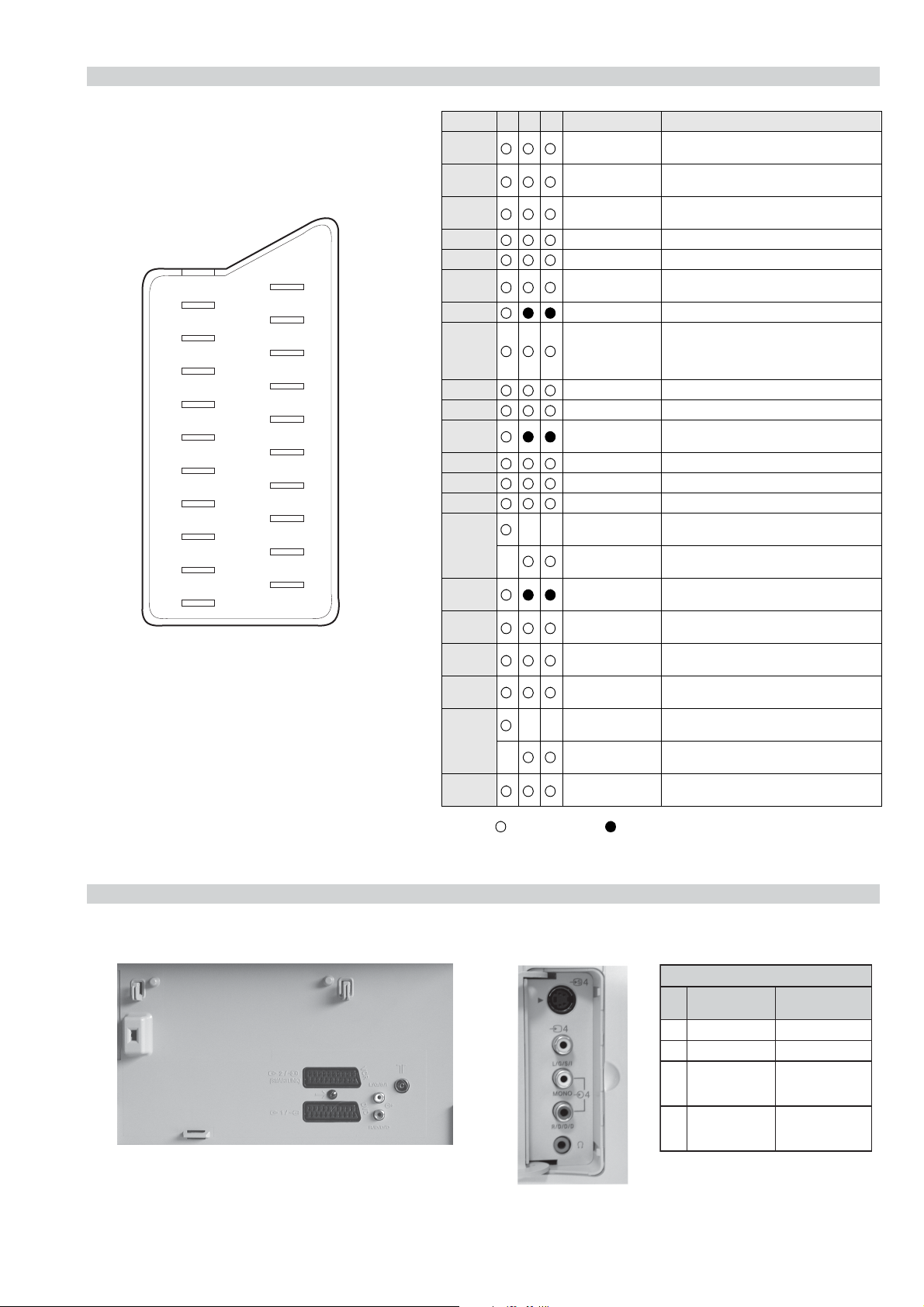
21 pin connector
21
19
17
15
13
11
9
7
5
3
1
20
18
16
14
12
10
8
6
4
2
Pin No 1 2 4 Signal Signal level
1 Audio output B
2
3
4 Ground (audio)
5 Ground (blue)
6 Audio input A
7 Blue input 0.7 +/- 3dB, 75 ohms positive
8 Function select
9 Ground (green)
10 Open
11 Green Green signal : 0.7 +/- 3dB, 75 ohms,
12 Open
13 Ground (red)
14 Ground (blanking)
15
_ (S signal Chroma
16 Blanking input
17 Ground (video
18 Ground (video
19 Video output 1V +/- 3dB, 75ohms, positive sync 0.3V
20
_ Video input
21 Common ground
(right)
Audio input B
(right)
Audio output A
(left)
(left)
(AV control)
_ _ Red input 0.7 +/- 3dB, 75 ohms, positive
input)
(Ys signal)
output)
input)
_ _ Video input 1V +/- 3dB, 75ohms, positive sync 0.3V
Y (S signal)
(plug, shield)
Standard level : 0.5V rms
Output impedence : Less than 1kohm*
Standard level : 0.5V rms
Output impedence : More than 10kohm*
Standard level : 0.5V rms
Output impedence : Less than 1kohm*
Standard level : 0.5V rms
Output impedence : More than 10kohm*
High state (9.5-12V) : Part mode
Low state (0-2V) : TV mode
Input impedence : More than 10K ohms
Input capacitance : Less than 2nF
positive
0.3 +/- 3dB, 75 ohms, positive
High state (1-3V) Low state (0-0.4V)
Input impedence : 75 ohms
(-3+10dB)
(-3+10dB)
1V +/- 3dB, 75ohms, positive sync 0.3V
(-3+10dB)
Connected Not Connected (open) * at 20Hz - 20kHz
Rear Connection Panel Front Connection Panel
S-Video
socket
niP
oN
1dnuorG-
2dnuorG-
3tupni)langisS(Y,mho57Bd3-/+V1
4tupni)langisS(CBd3-/+V3.0
langiS leveLlangiS
noitarugifnocniptekcosoediVS
V3.0.cnySevitisop
Bd01+3-
evitisop,mho57
.cnyS
- 5 -
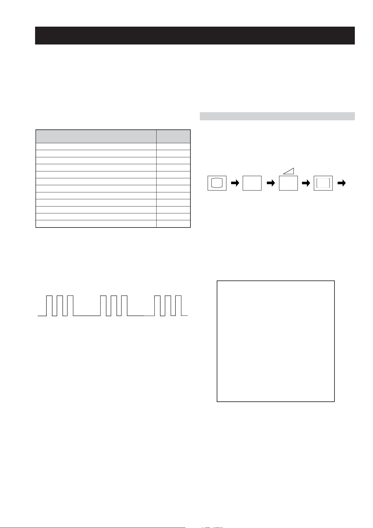
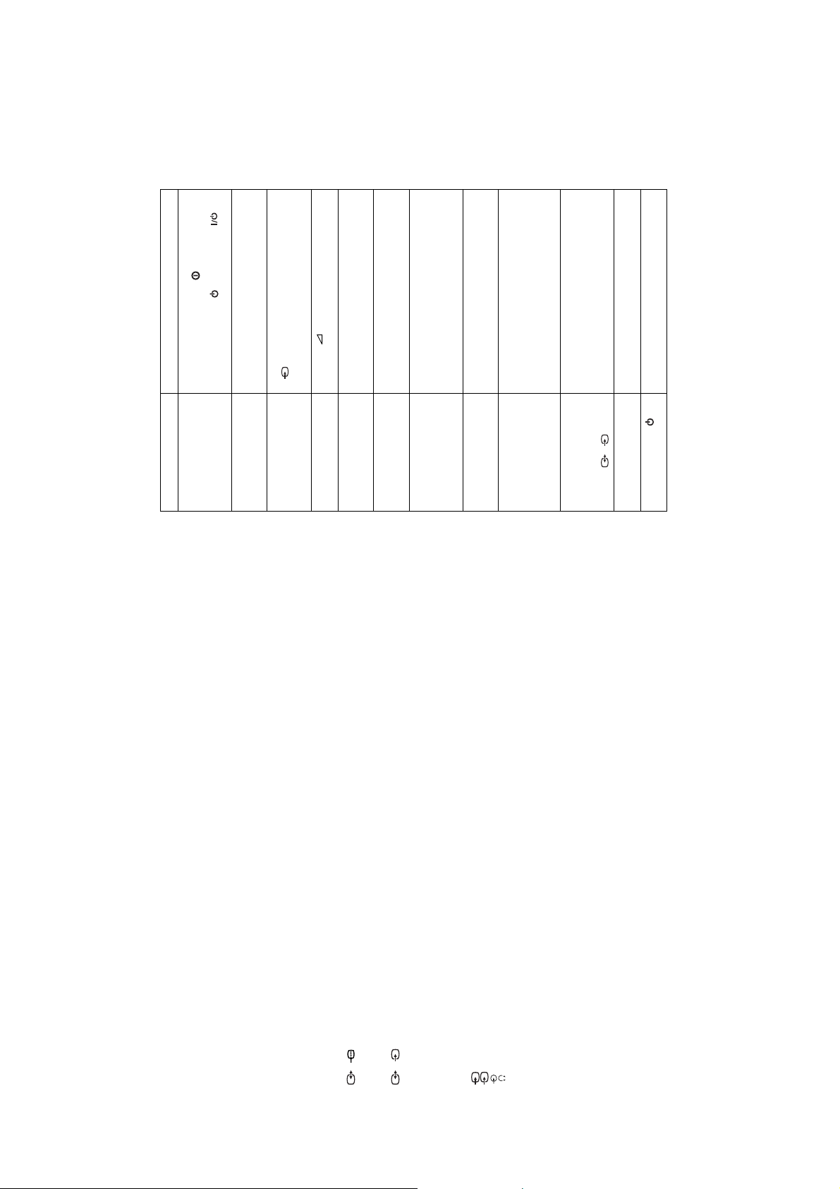
FE-2 SELF DIAGNOSTIC SOFTWARE
The identification of errors within the FE-2 chassis is triggered in one of two ways :- 1: Busy or 2: Device failure to respond to IIC. In the event
of one of these situations arising the software will first try to release the bus if busy (Failure to do so will report with a continuous flashing
LED) and then communicate with each device in turn to establish if a device is faulty. If a device is found to be faulty the relevant device number
will be displayed through the LED (Series of flashes which must be counted) See table 1., non fatal errors are reported using this method.Each
time the software detects an error it is stored within the NVM. See Table 2.
Table 1
egasseMrorrE
rorreoN00
devreseR10
)noitcetorPtnerruCrevO(PCO20
desUtoN30
cnySlacitreVoN40
norewoptarorrERKI50
norewoptaegdelwonkcasubCIIonMVN70
desUtoN80
norewoptaegdelwonkcaonrenuT90
rorrErossecorPdnuoS01
rorrestlov8rellortnocelgnuJ11
Flash Timing Example : e.g. error number 3
StBy LED
ON
ON ON
norewoptawolsenilatadro/dnakcolcsubCII60
How to enter into Table 2
DEL
edoC
1. Turn on the main power switch of the TV set and enter into
the ‘Standby Mode’.
2. Press the following sequence of buttons on the Remote
Commander.
i+
(ON SCREEN (DIGIT 5) (VOLUME -) (TV)
DISPLAY)
5
-
3. The following table will be displayed indicating the error
count.
Table 2
UNEMRORRE
OFF
OFF
:20E
:30E
:40E
:50E
:60E
:70E
:80E
:90E
:01E
:11E
:21E
:31E
:41E
SRUOH
SETUNIM
PCO
A/NPVO
CNYSV
RKI
CII
MVN
ELGNUJ
RENUT
PDNUOS
V8
AMME
XETROP
CTR
EMITGNIKROW
)552,0(
0
)552,0(
0
)552,0(
0
)552,0(
0
)552,0(
0
)552,0(
0
)552,0(
0
)552,0(
0
)552,0(
0
)552,0(
0
)552,0(
0
)552,0(
0
)552,0(
0
1
22
Note: To clear the error count data press ‘80’ on the Remote
commander.
- 6 -
SECTION 1 GENERAL
Yes
automatic tuning?
Do you want to start
select Yes.
The Auto Tuning menu appears on the screen. Press the OK button to
5
OK
No
Auto Tuning
System: B/G
Programme: 01
Searching...
Channel: C21
channels for you. This procedure could take some minutes. Please be
patient and do not press any buttons, otherwise the automatic tuning will not
be completed.
The TV starts to automatically search and store all available broadcast
6
If no channels were found during the auto tuning process then a new menu
Confirm
No channel found
Please connect aerial
appears automatically on the screen asking you to connect the aerial.
Please connect the aerial (see page 7) and press OK. The auto tuning
process will start again.
OK
Programme Sorting
Sorting menu appears automatically on the screen enabling you to change
After all available channels are captioned and stored, the Programme
7
Programme:
the order in which the channels appear on the screen.
01 TVE
02 TVE2
03 TV3
04 C33
05 C27
06 C58
a) If you wish to keep the broadcast channels in the tuned order, go to step 8.b) If you wish to store the channels in a different order:
OK
MENU
Select channel:
Exit:
OK
Programme:
01 TVE
ii) Press the or button to select the new programme number position
02 TVE2
03 TV3
04 C33
05 C27
for your selected channel (TV Broadcast), then press .
MENU
06 C58 05 C27
Select new position:
Exit:
iii) Repeat steps b)1 and b)2 if you wish to change the order of the other
channels.
Press the MENU button to remove the menu display from the TV screen.
8
Your TV is now ready for use.
First Time Operation
8
Programme Sorting
i) Press the or button to select the programme number with the
channel (TV Broadcast) you wish to rearrange, then press the button.
The operating instructions mentioned here are partial abstracts from the ‘Operating
Instruction Manual’. The page numbers of the ‘Operating Instruction Manual’ remain
as in the manual.
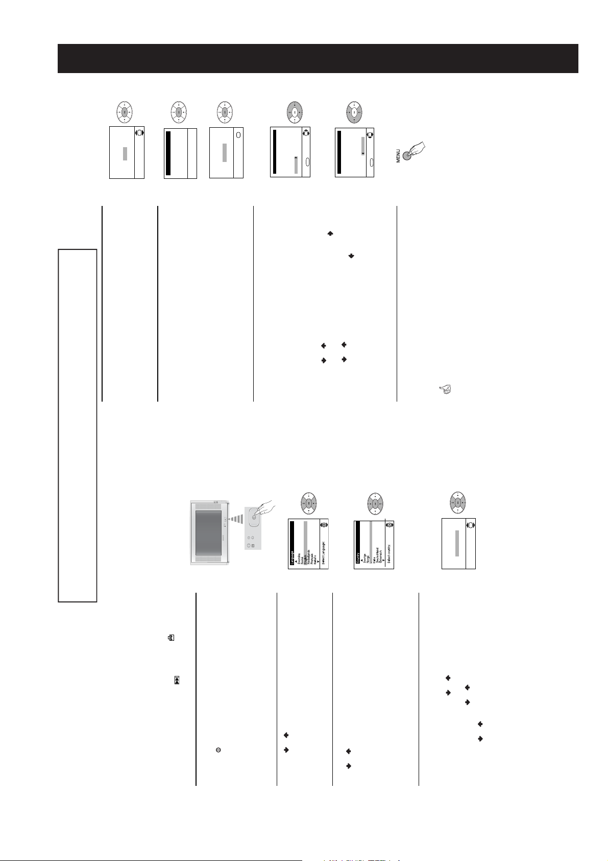
Switching on the TV and automatically
tuning in channels
The first time you switch on your TV, a sequence of menu screens appear on
the TV enabling you to: 1) choose the language of the menu screen,
2) choose the country in which you wish to operate the T V, 3) adjust the
picture slant, 4) search and store all available channels (TV broadcasts) and
5) change the order in which the channels (TV broadcas ts) appear on the
7
OK
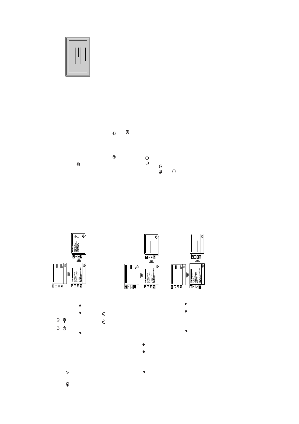
Adjust now
Not necessary
adjust picture rotation
If picture slants, please
recommend selecting ‘Russia’ if your own country does not appear in
Press the on/off button on the TV set to turn on the TV. The first time
you press this button, a Language menu displays automatically on the TV
screen.
Connect the TV plug to the mains socket (220-240V AC , 50Hz).
screen. However, if you need to change any of these settings at a later date,
you can do that by selecting the appropriate option in the (Set Up m enu)
1
or by pressing the Auto Start Up Button on the TV set.
then press the OK button to confirm your selection. From now on all the
menus appear in the selected language.
Press the or button on the remote control to select the language,
2
• If the country in which you want to use the TV set does not appear in
the or button to select the country in which you will operate the TV
set, then press the OK button to confirm your selection.
The Country menu appears automatically on the TV screen. Press
3
the list.
the list, select “-” instead of a country.
• To avoid wrong teletext characters for cyrillic languages we
press OK.
OK and correct any slant of the picture between –5 and +5 by
a) If it is not necessary, press or to select Not necessary and
Rotation menu allows you to correct the picture slants if it is necessary.
Because of the earth’s magnetism, the picture might slant. The Picture
4
pressing or . Finally press OK to store.
b) If it is necessary, press or to select Adjust now, then press
First Time Operation
- 7 -
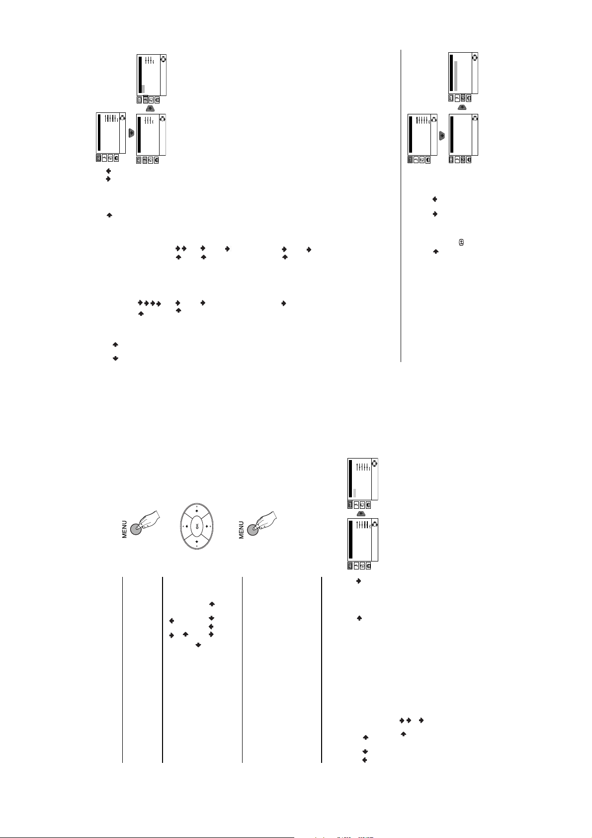
Sound Adjustment
Mode: Personal
Treble
Bass
Balance
OK
Reset
Dual Sound: Mono
Detail Adjustment
Timer
Sleep Timer: Off
OK
SOUND ADJUSTMENT
Picture Adjustment
Mode: Personal
Contrast
Brightness
The “Sound Adjustment” menu allows you to alter the sound s ettings.
Colour
To do this: after selecting the item you want to alter, press , then press / /
OK
Sharpness
Hue
Reset
Sound Adjustment
Mode: Personal
Treble
Bass
Balance
OK
Reset
Dual Sound: Mono
Detail Adjustment
Picture Adjustment
Mode: Personal
Contrast
Brightness
Colour
OK
Sharpness
Hue
Reset
Timer
Sleep Timer: Off
OK
or to s et the
according to the
effect.
changes
broadcast signal.
channels will stay
the same,
independent
of the broadcast
signal (e.g. in the
amplifier connected to
the audio outputs on
case of
advertisements).
the rear of the TV set.
button on the remote
Spatial: Acoustic sound
Pop
Sound Effect: Off: Normal.
Jazz
Detail Adjust ment
Rock
or repeatedly to adjust it and finally press OK to store t he new adjustment.
This menu also contains two submenus as following:
Mode Personal (for individual settings)
On: Volume level of the
Auto volume: Off: Volume level
On: Sound from the TV set.
TV Speakers: Off: Sound from external
control to display the time remaining.
channel 1, B for sound channel 2 or Mono for mono channel if available. For
• Treble and Bass can only be altered if “P ersonal” mode is selected.
a stereo broadcast you can choose Stereo or Mono.
•Select Reset and press OK to reset the sound to the factory preset levels.
• In case of a bilingual broadcast select Dual Sound and set A for sound
SLEEP TIMER
The “Sleep Timer” option in the “Timer” menu allows you to select a time period
for the TV to switch itself automatically into the standby mode.
To do this: after selecting the option press , then press
time period delay (max. of 4 hours) and finally press OK to store.
• While watching the TV, you can press the
remaining is displayed on the TV screen automatically.
• One minute before the TV switches itself into standby mode, the time
Menu System
10
Introducing and Using the Menu System
Your TV uses an on-screen menu system to guide you through the
operations. Use the following buttons on the remote control to operate the
menu system:
OK
9
Picture Adjustment
Mode: Personal
Contrast
Brightness
Colour
Sharpness
Hue
Reset
OK
Picture Adjustment
Mode: Personal
Contrast
Brightness
Colour
Sharpness
Hue
Reset
Digital Set Top Box receivers).
Movie (for films).
Live (for live broadcast programmes, DVD and
programme you are watching:
• To enter to the selected menu or option, press .
• To return to the last menu or option, press .• To alter settings of your selected option, press // or .
TV screen.
Press the MENU button on the remote control to display the menu on the
1
• To highlight the desired menu or option, press or .
2
• To confirm and store your selection, press OK.
Press the MENU button to remove the menu from the s creen.
3
Menu Guide
/ or repeatedly to adjust it and finally press OK to store the new
PICTURE ADJUSTMENT
The “Picture Adjustment” menu allows you to alte r the picture settings.
To do this: after selecting the item you want to alter press , then press /
adjustment.
Mode Personal (for individual settings).
• This menu also allows you to customise the picture mode based on the
• Brightness, Colour and Sharpn ess can only be altered if “Personal”
mode is selected.
• Hue is only available for NTSC colour signal (e.g: USA video tapes).
levels.
•Select Reset and press OK to reset the picture to the factory preset
Menu System
- 8 -
Picture Adjustment
Mode: Personal
Contrast
Brightness
Colour
13
4:3
OK
Sharpness
Hue
Reset
Smart
14:9
Zoom
Wide
Picture Adjustment
Mode: Personal
Contrast
Brightness
Colour
OK
Sharpness
Hue
Reset
Menu System
repeatedly on the
or to adjust the position of the image on the screen
automatically change the aspect ratio of the screen.
AUTO FORMAT
The “Auto Format” option in the “Detail Set Up” menu allows you to
OK
Picture Adjustment
Mode: Personal
Contrast
Brightness
Colour
Sharpness
Hue
Reset
To do this: after selecting the option, press . Then press or to select
On (if you wish the TV set to automatically switch the s creen format according
to the broadcast signal) or Off (if you wish to keep y our preference). Finally
press OK to store.
Even if you have selected “On” or “Off” in the “Auto Format” option, you can
always modify the format of the screen by pressing
remote control to select one of the following formats:
Smart: Imitation of wide screen effect for 4:3 broad cast.
Picture Adjustment
Mode: Personal
Contrast
Brightness
Colour
4:3: Conventional 4:3 picture size, full picture information.
14:9: Compromise between 4:3 an d 16:9 picture size.
Zoom: Widescreen format for letterbox movies.
Wide: For 16:9 broadcast. Full picture information.
(e.g. to rea d subtitles).
Note: In “Smart”, “Zoom” and “14:9” modes, parts of the top and bottom of the
screen are cut off. Press
NOISE REDUCTION
The “Noise Reduction” option in the “Detail Set Up” menu allows you to
automatically reduce the picture noise visible in the broadcast signal.
above.
To do this: after selecting the option, press . Then press or to select
Auto. Finally press OK to confirm and store.
To cancel this function afterwards, select “Off” instead of “Auto” in the step
11
OK
Sharpness
Hue
Reset
Picture Adjustment
Mode: Personal
Contrast
Brightness
Colour
OK
Sharpness
Hue
Reset
Picture Adjustment
Mode: Personal
Contrast
Brightness
Colour
OK
Sharpness
Hue
Reset
Menu System
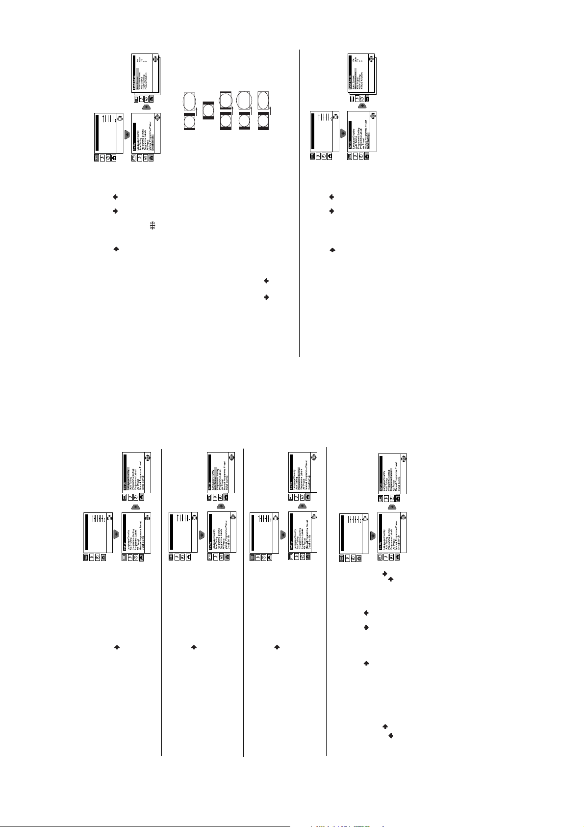
or to select the
language that the menus are displayed in. It also allows you to select the
country in which you wish to operate the TV set.
LANGUAGE / COUNTRY
The “Language/Country” option in the “Set Up” menu allows you to select the
confirm this character. Select the other four characters in the same way.
Finally press OK to store.
or to select a letter or number (select “-“ for a blank), then press to
Automatically Tuning”.
To do this: after selecting the option, press and then proceed in the same
way as in the steps 2 and 3 of the section “Switching On the TV and
search for and store all available TV channels.
To do this: after selecting the option, press and then proceed in the sam e
AUTO TUNING
The “Auto Tuning” option in the “Set Up” menu allows you to automatically
way as in TV steps 5 and 6 of the section “Switching On the TV and
Automatically Tuning” on page 8.
PROGRAMME SORTING
the order in which the channels (TV broadcast) appear on the screen.
The “Programme Sorting” option in the “Set Up” menu allows you to change
To do this: after selecting the option, press and then proceed in the same
way as in step 7b) of the section “Switching On the TV and Automatically
Tuning” on page 8.
PROGRAMME LABELS
The “Programme Labels” option in the “Set Up” menu allows you to name a
programme number with the channel you wish to name.
channel using up to five characters (letters or num bers). To do this:
1 After selecting the option, press , then press
2 Press . With the first element of the Label column highlighted, press
- 9 -
25
98
153
101
TELETEXT
Index
Programme
News
Sport
Weather
15
Teletext
Teletext
Teletext is an information service transmitted by most TV stations. The index
page of the teletext service (usually page 100) gives you information on how
Picture Adjustment
Mode: Personal
to use the service. To operate teletext, use the remote control buttons as
indicated below. Please ensure you use a channel (TV Broadcast) with a
strong signal, otherwise teletext errors may occur.
To switch on Teletext :
After selecting the TV channel which carries the teletext service you wish to
view, press .
OK
Contrast
Brightness
Colour
Sharpness
Hue
Reset
in order you can
or front connectors
S
2/
1/
not available. In that case, input another page number.
To select a Teletext page:
Input 3 digits for the page number, using the numbered buttons.
• If you have made a mistake, retype the correct page number.
• If the counter on the screen continues searching, it is because this page is
To access the next or preceding page:
Press PROGR + () or PROGR - ().
To superimpose teletext on to the TV:
Whilst you are viewing teletext, press . Press it again to cancel teletext
mode.
To freeze a teletext page:
Some teletext pages have sub-pages which follow on automatically. To stop
them, press / . Press it again to cancel the freeze.
To reveal concealed information (e.g: answer to a quiz):
Press / . Press it again to conceal the information.
To Switch Off Teletext:
Press .
OK
On
AutoTV0
0
Detail Set Up
Auto Format:
Noise Reduction:
AV2 Output:
RGB Centring:
Picture Rotation:
OK
Picture Adjustment
Mode: Personal
Contrast
Brightness
Colour
Sharpness
Hue
Reset
or to a VCR
S
Picture Adjustment
Mode: Personal
Contrast
Brightness
Colour
Sharpness
Hue
Reset
Fastext
Fastext service lets you access pages with one but ton push. When you are
in Teletext mode and Fastext is being broadcast, a colour coded menu
appears at the bottom of the teletext page. Press the c olour button (red,
green, yellow or blue) to access the corresponding page.
OK
On
AutoTV0
0
OK
On
AutoTV0
0
Detail Set Up
Detail Set Up
Auto Format:
Noise Reduction:
AV2 Output:
RGB Centring:
Picture Rotation:
Auto Format:
Noise Reduction:
AV2 Output:
RGB Centring:
Picture Rotation:
OK
2/
AV2 OUTPUT
The “AV2 Output” option in the “Detail Set Up” menu allows you to select the
3 and 3.
source to be output from the Scart connector
record from this Scart any signal coming from the TV or from external
If your VCR supports SmartLink, this procedure is not necessary.
equipment connected to the Scart connector
To do this: after selecting the option, press . Then press or to select
on the screen.
the desired output signal: TV, AV1, AV3 or AUTO.
If you have connected a decoder to the scart connector
Notes:
If you select “AUTO”, the output signal will always be the same one that is displayed
connected to this sca rt, please remember to chang e back the “AV2 Output” to
“AUTO” or “TV” for correct unscrambling.
RGB CENTRING
To do this: while watching an RGB source select the “RGB Centring” option
and press . Then press or to adjust the centre of the picture
it through the “RGB Centring” option in the “Detail Set Up”.
between –10 and +10. Finally press OK to confirm and store.
When connecting an RGB source, such as a “PlayStation”, you may need to
readjust the horizontal position of the picture. In that case, you can readjust
PICTURE ROTATION
Because of the earth’s magnetism, the picture may slant. In this case, you
To do this: after selecting the option, press . Then press or to
correct any slant of the picture between -5 and +5 and finally press OK to
“Detail Set Up” menu.
store.
can correct the picture slant by using the option “Picture Rotation” in the
Menu System
14
- 10 -
2-023-261-61
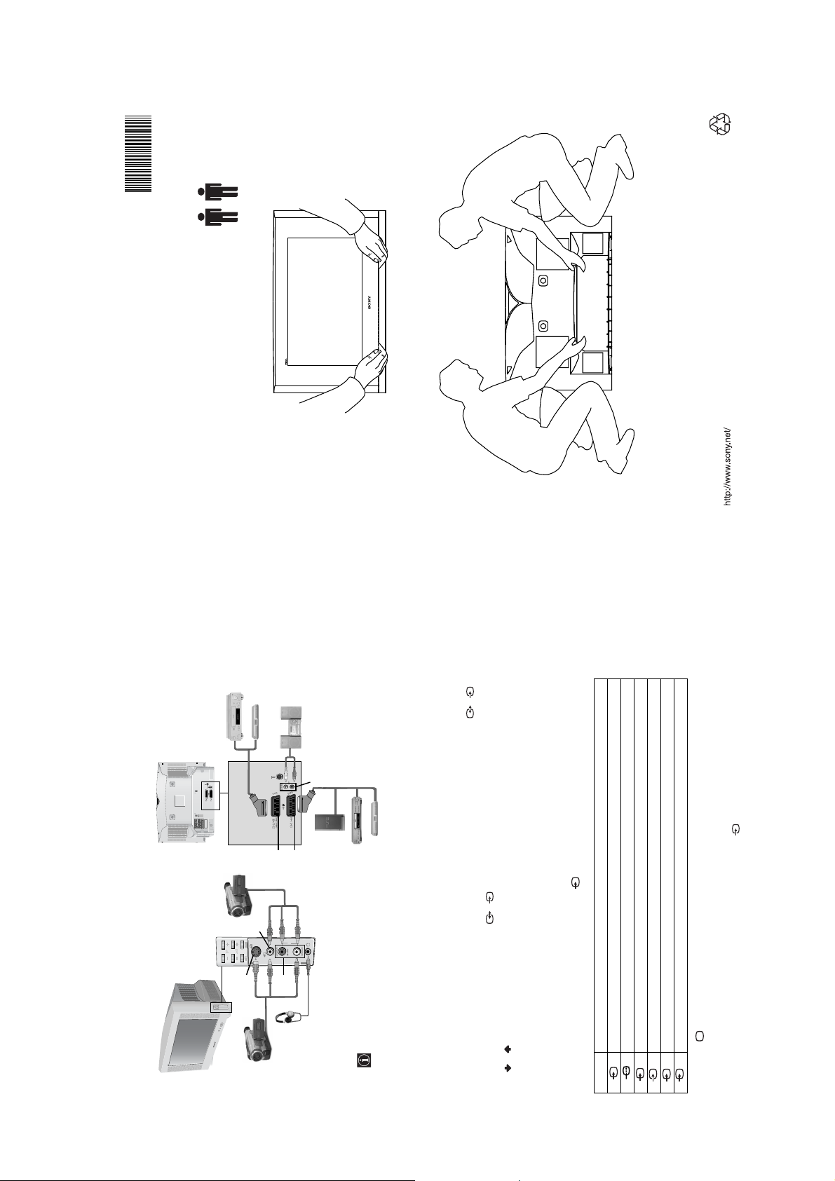
Lifting the TV Set
Recyclable
202326161
KV-28HX15U/32HX15U
Sony Corporation Printed in UK
Connecting Optional Equipment
S
D
MANUFACTURED UNDER LICENCE
FROM DOLBY LABORATORIES
"DOLBY" AND THE DOUBLE - D
SYMBOL ARE TRADEMARKS OF
DOLBY LABORATORIES
E
F
S
B
3
o3
3
A
C
speakers will automatically be muted.
When you connect the headphon es, the TV
“PlayStation” is a product of S ony Computer Entertainment, Inc.* “PlayStation” is a trademark of Sony Compu ter Entertainment, Inc.
*
Using the following instructions you can connect a wide range of optional equipment to your TV set. (Connecting cables are not
supplied).
Connecting a VCR:
To connect a VCR, please refer to the section “Connecting the aerial and VCR” of this instruction manual. We recommend you connect
Connecting a VCR that supports SmartLink:
SmartLink is a direct link between the TV set and the VCR. For more information on SmartLink, please refer to the instruction manual
of your VCR. If you use a VCR that supports SmartLink, please connect the VCR by using a scart lead to the Scart 2/ F.
If you have connected a decoder to the scart 2/ or through a VCR connected to this scart:
your VCR using a scart lead. If you do not have a scart lead, tune in the VCR test signal to the TV programme number “0” by using the
“Manual Programme Preset” option. (for details of how to manually programme these presets, see page 14, step a). Refer to your VCR
instruction manual to find out how to find the output channel of your VCR.
Select the “Manual Programme Preset” option in the “Set Up” menu and after entering in the “Decoder**” option, select “On” (by
using or ). Repeat this option for each scrambling signal.
**This option is only available depending on the country you have selected in the ‘Language/Country’ menu.
Using Optional Equipment
1 Connect your equipment to the designated TV socket, as indicated in the previous page.
screen.
2 Switch on the connected equipment.
3 To watch the picture of the connected equipment, press the button repeatedly until the correct input symbol appears on the
RGB input signal through the scart connector E. This symbol appears only if a RGB source has been connected.
3 Video input signal through the phono socket B and audio input signal through C.
2 S Video input signal through the scart connector F.
3 S Video input signal through the phono socket A and audio input signal through C.
2 Audio / video input signal through the scart connector F.
S
1 Audio / video input signal through the scart connector E.
Symbol Input Signals
S
4 Press the button on the remote control to return to the normal TV picture.
Additional Information
16
For Mono Equipment
Connect the phono plug to the L/G/S/I socket on the front of the TV and select 3 input signal using the instructions above. Finally,
refer to the “Sound Adjustment” section of this manual and select “Dual Sound” “A” on the sound menu screen.
- 11 -
button repeatedly on the remote control until the
option in the “Detail Set Up” menu and select “Auto” to
reduce the picture noise.
Programme Preset” menu and adjust Fine Tuning
(AFT) to obtain a better picture reception.
picture slant.
factory settings.
connector on the rear of the TV.
Country” menu and select the country in which you
factory settings.
• Check that the optional equipment is on and press the
correct input symbol is displayed on the screen.
the TV.
• Check the aerial connection.
• Plug the TV in and press the button on the front of
Adjustment” menu and select “Reset” to return to the
button on the remote control.
• If the standby indicator is on, press the
• Using the menu system, select the “Picture
Adjustment” menu and select “Reset” to return to
• Using the menu system, select the “Picture
• Turn off any equipment connected to the scart
• Check that the headphones are not connected.
are operating the TV set. For cyrillic languages, we
• Using the menu system, display the “Language/
option in the “Detail Set Up” menu to correct the
recommend selecting ‘Russia’ if your own country
does not appear in the list.
• Using the menu system, select the “Noise Reduction”
• Using the menu system, select the “Manual
Output” to “TV”.
Then select the “Detail Set Up” option and set “AV2
• Using the menu system, display the “Set Up” menu.
• Replace the batteries.
• Contact your nearest Sony service centre.
.
S
2/
Problem Solution
No picture (screen is dark) and
Troubleshooting
Here are some simple solutions to the problems which may affect the picture and sound.
no sound.
Poor or no picture (screen is
dark), but good sound.
No picture or no menu
information from equipment
No unscrambled picture whilst
viewing un unscrambled
channel with a decoder
connected through the scart
Noisy picture when viewing a
Distorted picture when
changing programmes or
selecting teletext.
Wrong characters appear
connected to the scart
connector.
Good picture, no sound. • Press the + button on the remote control.
No colour on colour
programmes.
when viewing teletext.
The TV picture is slanted • Using the menu system, select the “Picture Rotation”
TV channel.
connector
Remote control does not
function.
The standby indicator on
the TV flashes.
If you continue to experience problems, have your TV serviced by qu alified personnel.
Never open the casing yourself.
Additional Information
18
17
Additional Inf ormation
Specifications
Sound Output:
2 x 14W (music power)
2 x 7W (RMS)
TV system:
Depending on your country selection: IColour system:
your TV set and a compatible
VCR. For more information on
SmartLink, please refer to your
Power Consumption:
28” : 72 W
32” : 75 W
Standby Power Consumption:
0.5 W
Dimensions (w x h x d) :
28” : Approx. 844 x 517 x 548 mm
32” : Approx. 933 x 562 x 572 mm.
Weight:
28” : Approx. 44.5 Kg
32” : Approx. 60.0 Kg
Accessories supplied:
1 remote control (RM-947)
2 x IEC designated AA size
batteries
Other features:
• Teletext, Fastext, TOPtext.
• Sleep Timer.
21-pin scart connector (CENELEC
(SMARTLINK)
S
2/ 2
standard) including audio/video input,
RGB input, TV audio/video output.
21-pin scart connector (CENELEC
standard) including audio/video input, S
1
/
1
PAL, SECAM
NTSC 3.58, 4.43 (only Video In)
Channel Coverage:
UHF: B21-B69
Picture Tube:
Flat Display FD Trinitron WIDE
28” (approx. 71 cm. measured diagonally)
32” (approx. 82 cm. measured diagonally)
Rear Terminals
VCR instruction manual).
• SmartLink (direct link between
video input, selectable audio/video output
and SmartLink interface.
Front Terminals
• TV system autodetection.
3 S-video input – 4 pin DIN
3 video input – phono jack
S
headphones jack
3 audio input – phono jacks
Design and specifications are subject to change withou t notice.
- 12 -
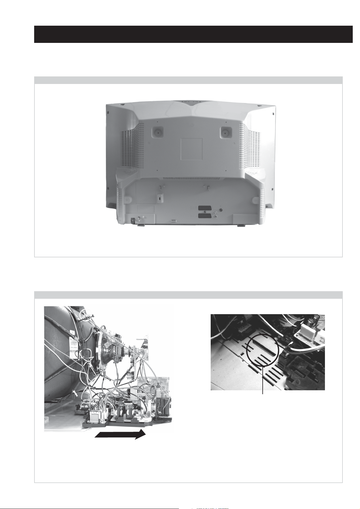
2-1. Rear Cover Removal
=>
<=
SECTION 2 DISASSEMBLY
<=
<=
<=
=>
=>
=>
Remove the rear cover fixing screws indicated and withdraw the rear cover from the Beznet.
2-2. Chassis Removal and Refitting
=>
=>
=>
To remove lift the main bracket rear slightly and slide the
chassis away from the beznet. Ensure that the interconnecting
leads are released from their purse locks to prevent damage
being caused.
When refitting the chassis ensure that the main
bracket is located in the beznet guide slots before
sliding the chassis forwards. Refit the
interconnecting leads in their respective purse locks.
- 13 -
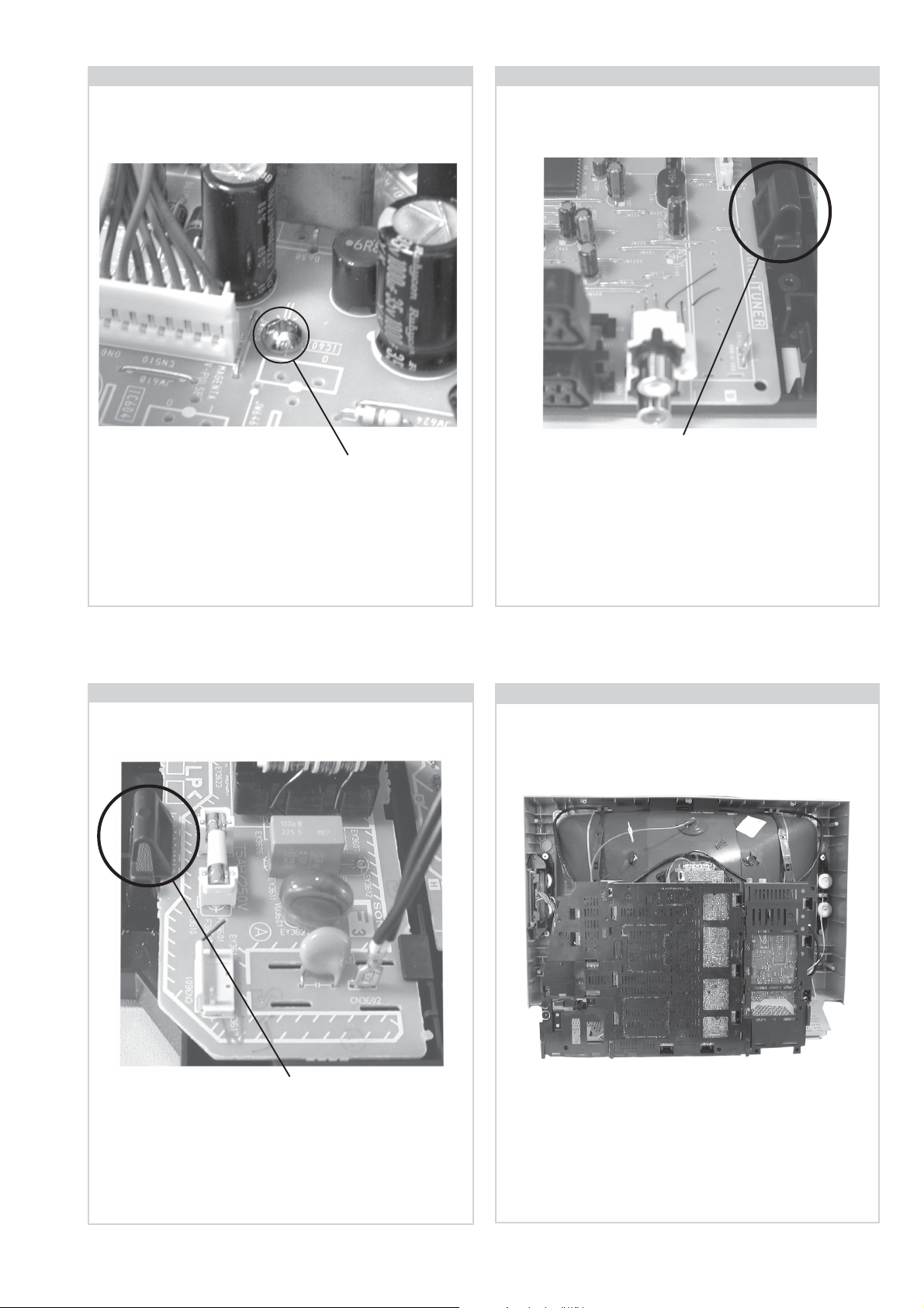
2-3. A Board Removal [ Step 1 ] 2-4. A Board Removal [ Step 2 ]
Clip.
Screw.
Remove the 3 screws securing the PWB to the main bracket.
1 can be seen in the photo above and the other 2 are either
side of the FBT assembly.
2-5. F3 Board Removal
Release the 5 securing clips located around the side of the
chassis and slide the PWB clear of the bracket.
2-6. Service Position
Clip.
Release the 2 securing clips located along the side of the
chassis and slide the PWB clear of the bracket.
Position the chassis as indicated to access the solder side
of the PWB’s. To gain access to the A Board follow the
instructions on page 16. [Removal and Replacement of the
main bracket bottom plates ].
- 14 -
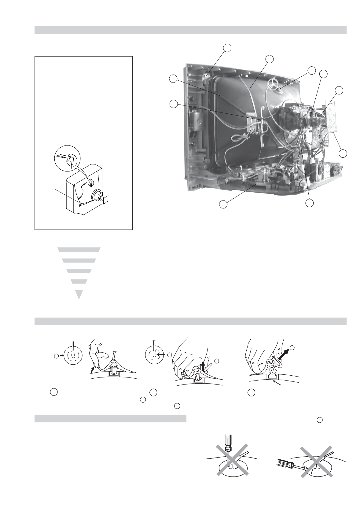
2-7. Picture Tube Removal
10
WARNING:
BEFORE REMOVING
THE ANODE CAP
High voltage remains in the CRT even
after the power is disconnected. To
avoid electric shock, discharge CRT
before attempting to remove the anode
cap. Short between anode and CRT
coated earth ground strap.
Coated Earth
Ground Strap
9
8
7
4
1. Discharge the anode of the CRT and remove the anode cap.
2. Unplug all interconnecting leads from the Deflection yoke, neck
assy, degaussing coils and CRT grounding strap.
3. Remove the C Board from the CRT.
4. Remove the chassis assembly.
5. Loosen the Neck assembly fixing screw and remove.
6. Loosen the Deflection yoke fixing screw and remove.
7. Place the set with the CRT face down on a cushion and remove
the Degaussing Coil holders.
8. Remove the Degaussing Coils.
9. Remove the CRT grounding strap and spring tensioners.
10. Unscrew the four CRT fixing screws [ located on each CRT
corner ] and remove the CRT.
[Take care not to handle the CRT by the neck.]
1
6
5
3
2
Removal of the Anode-Cap
* REMOVING PROCEDURES.
a
1
Turn up one side of the rubber cap in
the direction indicated by the arrow a
b
2 Using a thumb pull up the rubber cap
firmly in the direction indicated by the
arrow b
How to handle the Anode-Cap
1. To prevent damaging the surface of the anode-cap do not use
sharp materials.
2. Do not apply too great a pressure on the rubber, as this may cause
damage to the anode connector.
3. A metal fitting called a shatter hook terminal is fitted inside the
rubber cap.
4. Do not turn the rubber foot over excessively, this may cause
damage if the shatter hook sticks out.
c
b
Anode button
3 When one side of the rubber cap is
separated from the anode button, the
anode-cap can be removed by turning
up the rubber cap and pulling it up in
the direction of the arrow c
- 15 -
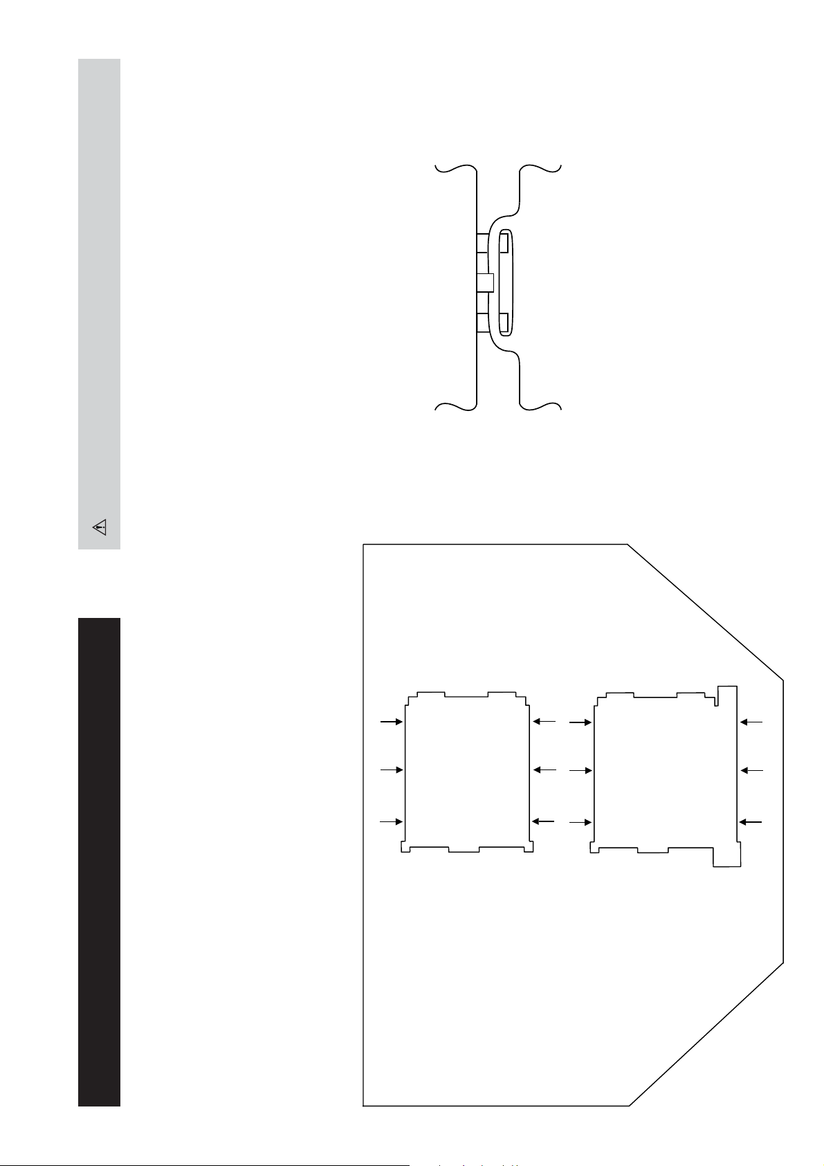
For safety reasons, on no account should the plates be re-
moved and not refitted after servicing.
(2) REFITTING THE PLATES
Because the plates differ in size it is important that the correct plates are refitted in their original
location.
Please note that the plates need to be rotated 180 degrees from their cut position to allow the tabs to
be fitted into their catch positions.
Catch
Ta b
REMOVAL AND REPLACEMENT OF THE MAIN-BRACKET
BOTTOM PLATES.
Only remove the necessary plate to gain access to the printed wiring board.
In the event of servicing being required to the solder side of the A Board printed wiring board, the
bottom plates fitted to the main chassis bracket require to be removed.
This is performed by cutting the gates with a sharp wire cutter at the locations indicated by the
arrows.
(1) REMOVING THE PLATES
Note : There are 2 plates fitted to the main bracket.
- 16 -
SECTION 3 SET-UP ADJUSTMENTS
• When complete readjustment is necessary or a new picture
tube is installed, carry out the following adjustments.
• Unless there are specific instructions to the contrary, carry
out these adjustments with the rated power supply.
• Unless there are specific instructions to the contrary, set the
controls and switches to the following settings :
Contrast .................... 80% [or remote control normal]
Brightness ................... 50%
Preparation:
1. In order to reduce the influence of geomagnetism on the
set’s picture tube, face it in an easterly or westerly direction.
2. Switch on the set’s power and degauss with the degausser.
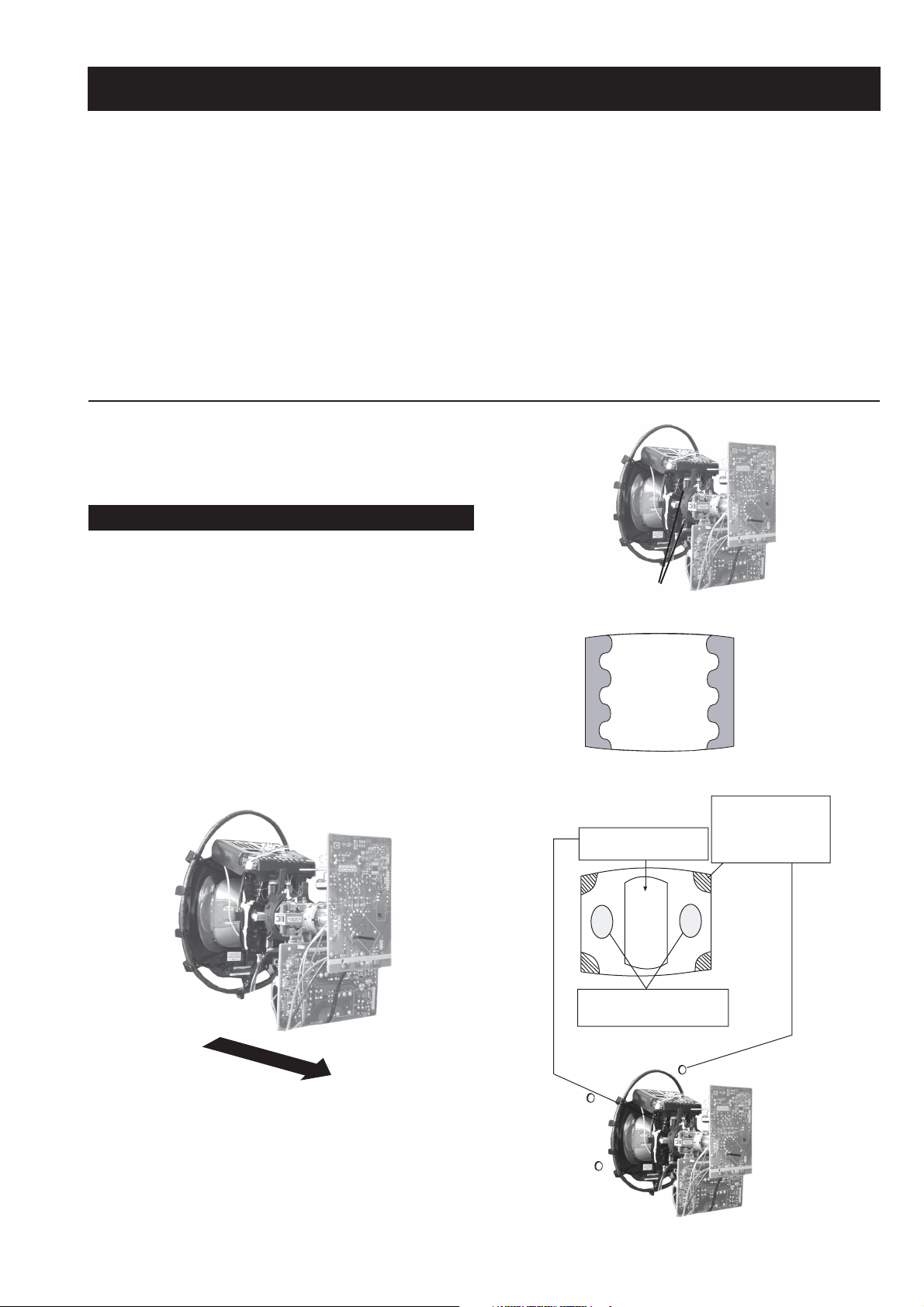
3-1. Beam Landing
1. Input an all white signal from the pattern generator. Set the
Contrast and Brightness to normal.
2. Set the pattern generator raster signal to Red.
3. Move the deflection yoke forward and adjust with the
purity control so that the Red is at the centre and the Blue
and Green take up equally sized areas on each side of the
screen. [See Fig.3-1 - 3-3].
4. Move the deflection yoke backwards and adjust so that the
entire screen becomes Red. [See Fig.3-1]
5. Switch the raster signal to Blue, then to Green and verify
the condition.
6. When the position of the deflection yoke has been
determined, fasten the deflection yoke with the screws.
7. If the beam does not land correctly in all the corners, use a
magnet to correct it. [See Fig.3-4]
Carry out the adjustments in the following order :
3-1. Beam Landing.
3-2. Convergence.
3-3. Focus.
3-4. White Balance.
Note : Test equipment required.
1. Color bar/pattern generator.
2. Degausser.
3. Oscilloscope.
4. Digital multimeter.
Fig. 3-2.
Purity
Fig. 3-3.
GREEN
RED
BLUE
Disk magnets or
rotatable disk
Purity control corrects
this area
magnets correct
these areas (a-d)
Fig. 3-1.
Caution :
High voltages are present on the Deflection yoke terminals
- take care when handling the Deflection yoke whilst carrying
out adjustments.
- 17 -
Fig.3-4
ab
c
Deflection yoke positioning
corrects these areas
Disk Magnets
d
GBR
GBR
GBR
G
B
R
GBR
G
B
R
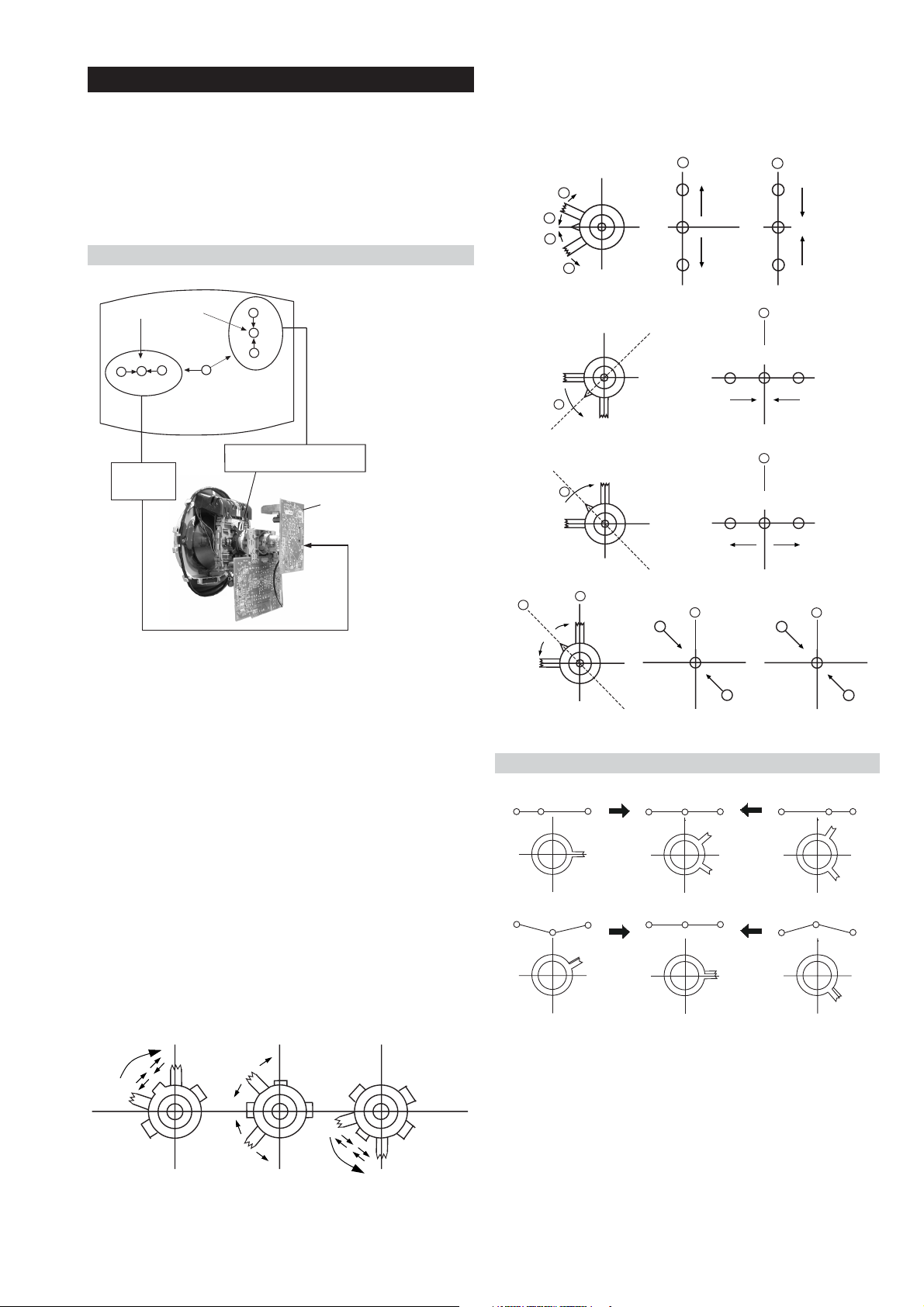
3-2. Convergence
B
G
R
a
b
R
G
B
b
a
Preparation:
4. If the V.STAT magnet is moved in the direction of the (a)
and (b) arrows, the Red, Green and Blue points move as
indicated below.
• Before starting this adjustment, adjust the focus, horizontal
size and vertical size.
• Minimize the Brightness setting.
• Input a dot pattern from the pattern generator.
Horizontal and Vertical Static Convergence
Center dot
R
G
B
H STAT
convergence
control
R
G
B
V.STAT Vertical Static Magnet
C Board
RV702 (H STAT)
H STAT Convergence
(on mount side)
a
b
a
a
b
a
b
B
G
R
R
R
b
B
G
R
a
B
G
b
B
G
Fig.3-5
1. [Moving horizontally], adjust the H.STAT control so that
the Red, Green and Blue points are on top of each other at
the centre of the screen.
Operation of the BMC (Hexapole) magnet.
2. [Moving vertically], adjust the V.STAT magnet so that the
Red, Green and Blue points are on top of each other at the
centre of the screen.
3. If the H.STAT variable resistor is unable to bring the Red,
Green and Blue points together at the centre of the screen,
adjust the horizontal convergence with the H.STAT variable
resistor and the V.STAT magnet in the manner indicated
below.
[In this case, the H.STAT variable resistor and the V.STAT
magnet influence each other].
• Tilt the V.STAT magnet and adjust the static convergence by
opening or closing the V.STAT magnet.
The movement of the magnets interact with each other and so
the respective dot position should be monitored while carrying
out this adjustment.
Use the H.STAT VR to adjust the Red, Green and Blue dots so
that they coincide at the centre of the screen
(by moving the dots in the horizontal direction).
- 18 -
 Loading...