

Page 1

HISTORY INFORMATION FOR THE FOLLOWING MANUAL:
SERVICE MANUAL
ORIGINAL MANUAL ISSUE DATE: 2/2011
Version Date Subject
1.0 2/2011 Original manual issue.
AZ2EK CHASSIS
Segment: P-2S
LCD Digital Color TV
9-888-406-01
Page 2

SERVICE MANUAL
LCD Digital Color TV
AZ2EK CHASSIS
Segment: P-2S
9-888-406-01
Page 3

MODEL LIST
KLV-32NX520 Black RM-GA020 INDIA/VIETNAM
KLV-40NX520 Black RM-GA020 INDIA/VIETNAM
MODEL COLOR COMMANDER DEST.MODEL COLOR COMMANDER DEST.
KLV-32/40NX520(IN/VN)
3
Page 4

WARNINGS AND CAUTIONS -ENGLISH
CAUTION
These servicing instructions are for use by qualified service personnel only.
To reduce the risk of electric shock, do not perf orm any servicing other than that contained in the operating instructions unless you are qualified to do so.
WARNING!!
An isolation transformer should be used during any service to avoid possible shock hazard, because of live chassis.
The chassis of this receiver is directly connected to the ac power line.
CARRYING THE TV
Be sure to follow these guidelines to protect your property and avoid causing serious injury.
• Carry the TV with an adequate number of people; larger size TVs require two or more people.
• Correct hand placement while carrying the TV is very important for safety and to avoid damages.
SAFETY-RELATED COMPONENT WARNING!!
Components identified by shading and ! mark on the schematic diagrams, exploded views, and in the parts list are critical for safe operation. Replace these components with Sony
parts whose part numbers appear as shown in this manual or in supplements published by Sony. Circuit adjustments that are critical for safe operation are identified in this manual.
Follow these procedures whenever critical components are replaced or improper operation is suspected.
KLV-32/40NX520(IN/VN)
4
Page 5

WARNINGS AND CAUTIONS -FRENCH
ATTENTION!!
Ces instructions de service sont à l’usage du personnel de service qualifi é seulement.
Pour prévenir le risque de choc électrique, ne pas faire l’entretien autre que celui contenu dans le Mode d’emploi à moins que vous soyez qualifi é faire ainsi.
WARNING!!
Afi n d’eviter tout risque d’electrocution provenant d’un chássis sous tension, un transformateur d’isolement doit etre utilisé lors de tout dépannage. Le chássis de ce récepteur est
directement raccordé à l’alimentation du secteur.
POUR TRANSPORTER LE TÉLÉVISEUR
Tenez compte de ce qui suit pendant l’installation du téléviseur :
• Débranchez tous les câbles avant de transporter le téléviseur.
• Transportez le téléviseur avec le nombre de personnes approprié ; un téléviseur de grande taille doit être transporté par au moins deux personnes.
• Lors du transport du téléviseur, l’emplacement des mains est très important pour votre sécurité, ainsi que pour éviter de causer des dommages.
ALERTE!!
Afi n d’eviter tout risque d’electrocution provenant d’un chassis sous tension, un transformateur d’isolement doit etre utilise lors de tout depannage. Le chassis de ce recepteur est
directement raccorde a l’alimentation du secteur.
ATTENTION AUX COMPOSANTS RELATIFS A LA SECURITE!!
Les composants identifi es par une trame et par une marque ! sur les schemas de principe, les vues explosees et les listes de pieces sont d’une importance critique pour la securite du
fonctionnement. Ne les remplacer que par des composants Sony dont le numero de piece est indique dans le present manuel ou dans des supplements publies par Sony. Les reglages
de circuit dont l’importance est critique pour la securite du fonctionnement sont identifi es dans le present manuel. Suivre ces procedures lors de chaque remplacement de
composants critiques, ou lorsqu’un mauvais fonctionnement suspecte.
KLV-32/40NX520(IN/VN)
5
Page 6

USE CAUTION WHEN HANDLING THE LCD PANEL
When repairing the LCD panel, be sure you are grounded by using a wrist band.
When repairing the LCD panel on the wall, the LCD panel must be secured using the 4 mounting holes on the rear cover.
1) Do not press on the panel or frame edge to avoid the risk of electric shock.
2) Do not scratch or press on the panel with any sharp objects.
3) Do not leave the module in high temperatures or in areas of high humidity for an extended period of time.
4) Do not expose the LCD panel to direct sunlight.
5) Avoid contact with water. It may cause a short circuit within the module.
6) Disconnect the AC power when replacing the backlight (CCFL) or inverter circuit. (High voltage occurs at the inverter circuit at 650Vrms.)
7) Always clean the LCD panel with a soft cloth material.
8) Use care when handling the wires or connectors of the inverter circuit. Damaging the wires may cause a short.
9) Protect the panel from ESD to avoid damaging the electronic circuit (C-MOS).
10) It is recommended not to exceed 1 hour of Power-On nor Burn-in period with LCD panel face down condition, in repair activity.
WARNINGS AND CAUTIONS
KLV-32/40NX520(IN/VN)
6
Page 7

SAFETY CHECK-OUT
After correcting the original service problem, perform the following safety checks before releasing the set to the customer:
1. Check the area of your repair for unsoldered or poorly soldered connections. Check the entire board surface for solder splashes and bridges.
2. Check the interboard wiring to ensure that no wires are “pinched” or touching high-wattage resistors.
3. Check that all control knobs, shields, covers, ground straps, and mounting hardwar e have been replaced. Be absolutely certain that you have replaced all the insulators.
4. Look for unauthorized replacement parts, particularly transistors, that were installed during a previous repair. Point them out to the customer and recommend their replacement.
5. Look for parts which, though functioning, show obvious signs of deterioration. Point them out to the customer and recommend their replacement.
6. Check the line cords for cracks and abrasion. Recommend the replacement of any such line cord to the customer.
7. Check the antenna terminals, metal trim, “metallized” knobs, screws, and all other exposed metal parts for AC leakage. Check leakage as described below.
8. For safety reasons, repairing the Power board and/or Inverter board is prohibited.
KLV-32/40NX520(IN/VN)
7
Page 8

Leakage Test
The AC leakage from any exposed metal part to earth ground and from all exposed metal parts to any exposed
metal part having a return to chassis, must not exceed 0.5 mA (500 microamperes).
Leakage current can be measured by any one of three methods.
1. A commercial leakage tester, such as the Simpson 229 or RCA WT-540A. Follow the manufacturers’
instructions to use these instructions.
2. A battery-operated AC milliampmeter. The Data Precision 245 digital multimeter is suitable for this job.
3. Measuring the voltage drop across a resistor by means of a VOM or battery-operated AC voltmeter. The
“limit” indication is 0.75 V, so analog meters must have an accurate low voltage scale.
The Simpson’s 250 and Sanwa SH-63TRD are examples of passive VOMs that are suitable. Nearly all
battery-operated digital multimeters that have a 2 VAC range are suitable (see Figure A).
How to Find a Good Earth Ground
A cold-water pipe is a guaranteed earth ground; the cover-plate retaining screw on most AC outlet boxes is also
at earth ground.
If the retaining screw is to be used as your earth ground, verify that it is at ground by measuring the resistance
between it and a cold-water pipe with an ohmmeter. The reading should be zero ohms.
If a cold-water pipe is not accessible, connect a 60- to 100-watt trouble- light (not a neon lamp) between the hot
side of the receptacle and the retaining screw. Try both slots, if necessary, to locate the hot side on the line; the
lamp should light at normal brilliance if the screw is at ground potential (see Figure B).
SAFETY CHECK-OUT
KLV-32/40NX520(IN/VN)
8
Page 9
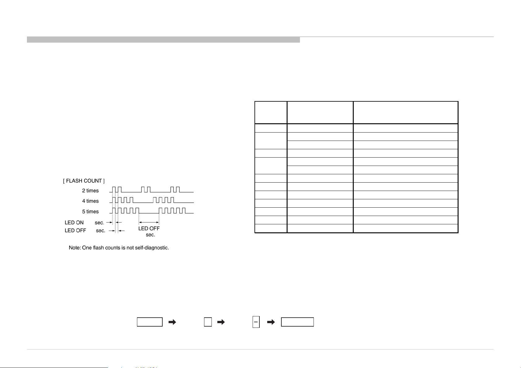
SELF DIAGNOSIS FUNCTION
The units in this manual contain a self-diagnostic function. If an error occurs, the STANDBY LED will automatically begin to flash.
The number of times the LED flashes translates to a probable source of the problem.
A definition of the STANDBY LED flash indicators is listed in the instruction manual for the user’s knowledge and reference.
If an error symptom cannot be reproduced, the remote commander can be used to review the failure occurrence data stored in memory to reveal past problems and how often these
problems occur.
DIAGNOSTIC TEST INDICATORS
When an error occurs, the STANDBY LED will flash a set number of times to
indicate the possible cause of the problem.
If there is more than one error, the LED will identify the first of the problem areas.
Result for all of the following diagnostic items are displayed on screen.
If the screen displays a “0”, no error has occurred .
DISPLAY OF STANDBY LED FLASH COUNT
0.5
0.5
3
STBY LED
Fla sh time
2 MAIN_POWE Main Power Over Voltage Prote ction
3
4 BALANCER Balancer Error
5
6 BACKLI TE Back Light Error (Panel Inve rter )
7
8 - Not used
9 - Not used
10 - Not used
11 - Not used
12 - Not used
Service menu Item
name
(Screen Di splay)
DC_ALERT DC_ALERT
AUDIO_ PORT Audio Abnormal Detection
TCON_ERR T-con Error
PA NEL_POWE Panel Error
TE MP_ERR T h ermal Error
D iagnost ic Item Descr iption
SELF-DIAGNOSTIC SCREEN DISPLAY
For errors with symptoms such as “power sometimes shuts off” or “screen sometimes goes out” that cannot be confirmed, it is possible to bring up past occurrences of failure for
confirmation on the screen:
[To Bring Up Screen Test]
In standby mode, press buttons on the remote commander sequentially in rapid succession as shown below:
*
Info TV POWERChannel Volume
KLV-32/40NX520(IN/VN)
5
* : Note that this differs from entering the service mode (volume +)
9
Page 10
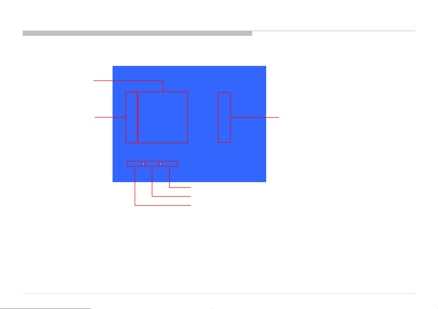
[SELF DIAGNOSTIC SAMPLE SCREEN DISPLAY]
SELF DIAGNOSIS FUNCTION
Item name
SELFCHECK
BACK <<
002MAIN_POWER 000
003AUDIO_PORT 000
003DC_ALERT 000
STBY LED flash time
004BALANCER 000
005TCON_ERR 000
005PANEL_POWE 000
006BACKLITE 000
007TEMP_ERR 000
12345‐67891‐23456
[Home]Exit
Panel operation time by hour
Boot count
Total operation time by hour
Since the diagnostic results displayed on the screen are not automatically cleared, always check the self-diagnostic screen.
After you have completed the repairs, clear the result display to “0”.
Error count
Clearing the Self Check Diagnostic List
1. Error history and Error count : Press the Channel 8 => Channel 0 .
2. Panel operation time : Press the Channel 7 => Channel 0 .
Exiting the Self-diagnostic scre en
To exit the Self Diagnostic screen, turn off the power to the TV by pressing the POWER button on the remote or the POWER button on the TV.
KLV-32/40NX520(IN/VN)
10
Page 11
SEC 1. DISASSEMBLY AND PARTS LIST
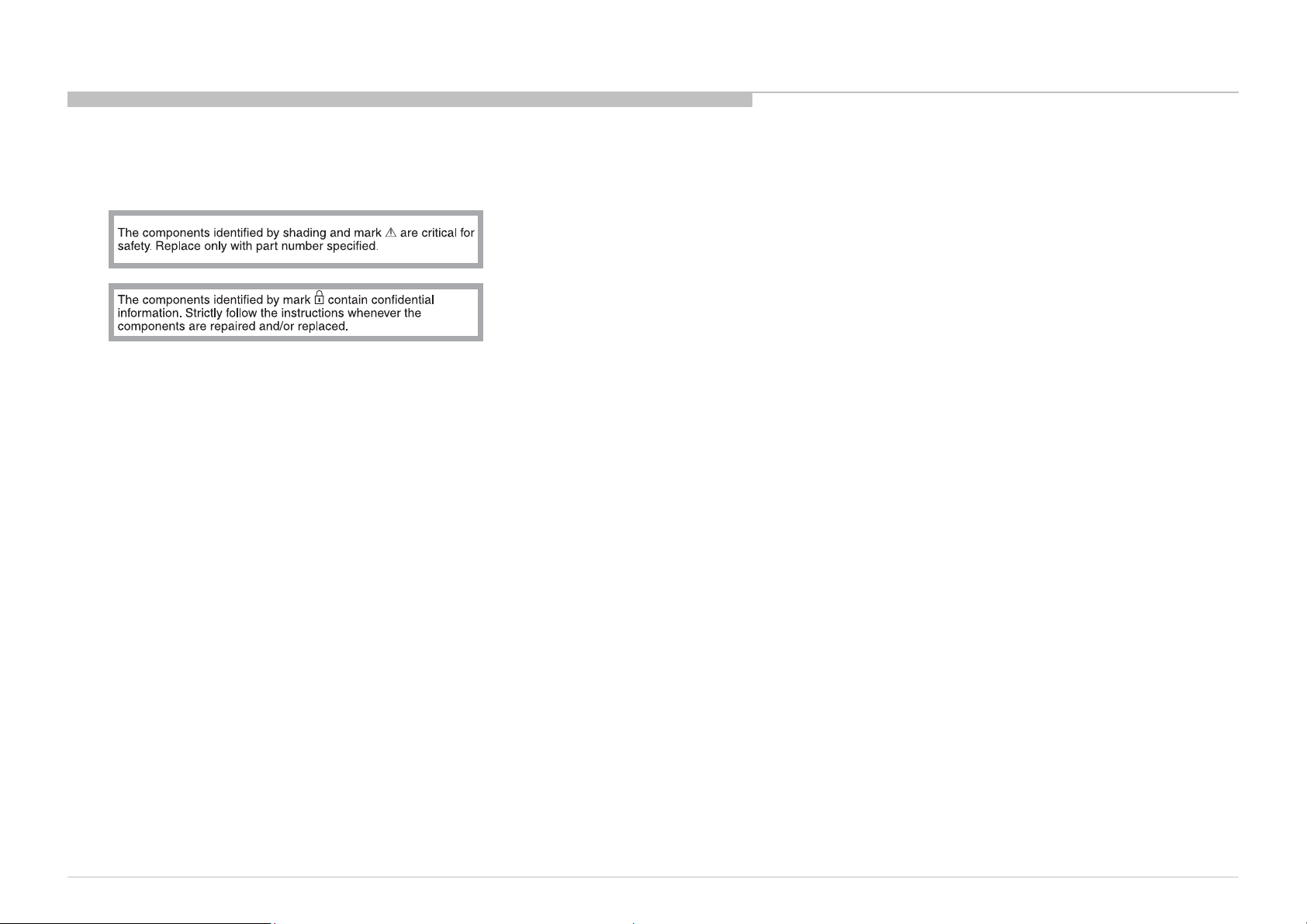
• Items with no part number and no description are not stocked because they are seldom required for roution service.
• The construction parts of an assembled part are indicated with a collation number in the remark colum.
• Items marked " * " are not stocked since they are seldom required for routine service. Some delay should be anticipated when ordering these items.
KLV-32/40NX520(IN/VN)
11
Page 12
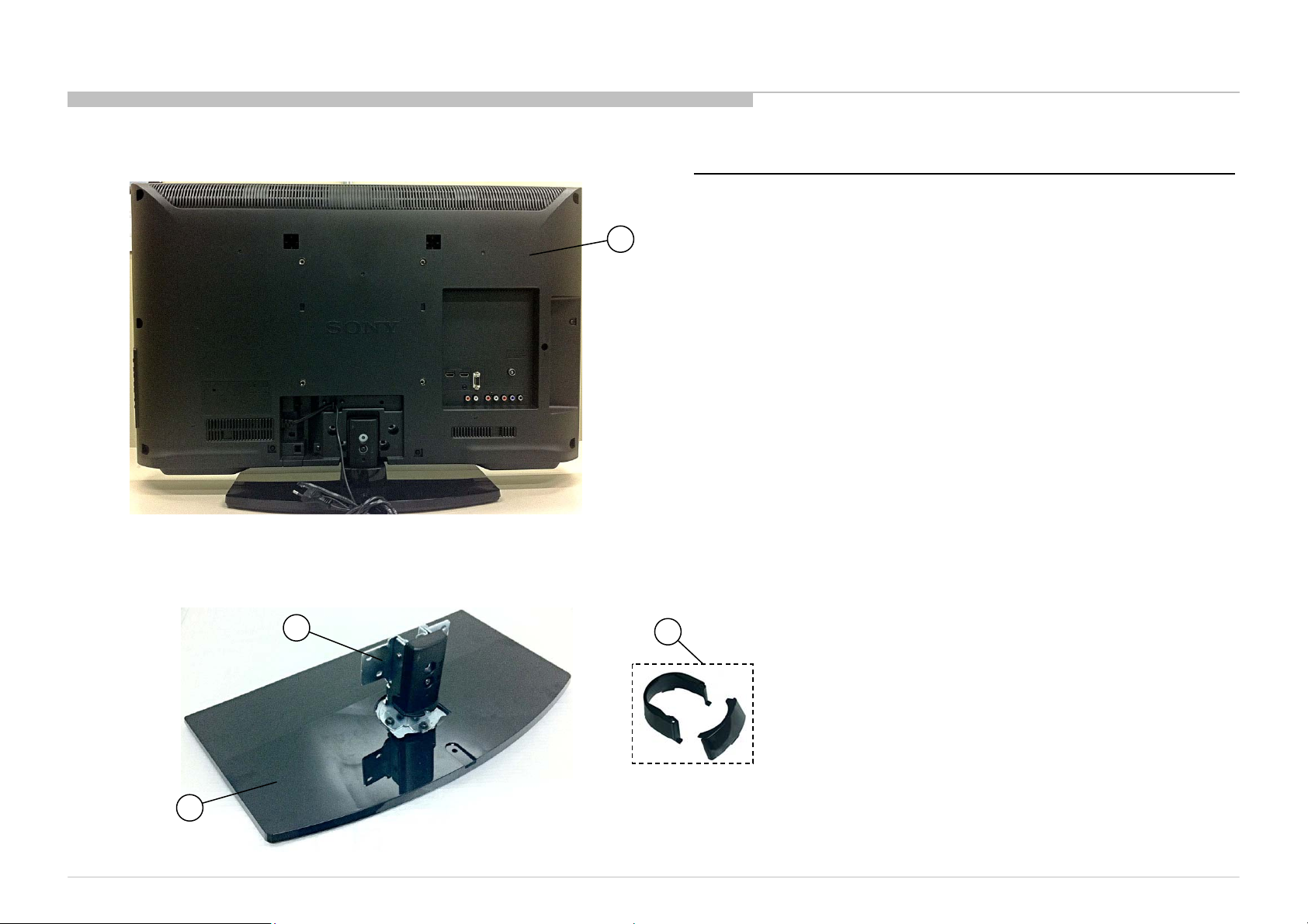
1-1. KLV-32NX520
DISASSEMBLY AND PARTS LIST
1-1-1. REAR COVER ASSY AND STAND BLOCK
1-1-2. NECK COVER, NECK AND BASE ASSY
REF. No . PAR T No . DES CRI P TI O N MARK
1 4-274-582-01 REAR COVER (RW32)
2 X-2546-339-1 NECK (M2) ASSY
3 X-2580-825-1 BASE (M7) AS SY
1
4 X-2546-540- 1 COVER (M3) ASSY
3
KLV-32/40NX520(IN/VN)
2
4
12
Page 13
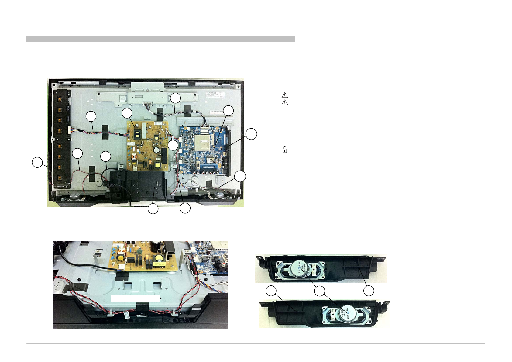
1-1. KLV-32NX520
DISASSEMBLY AND PARTS LIST
1-1-3. G13 BOARD, A BOARD, SWITCH UNIT AND SIDE BRACKET
10
7
6
5
8
9
11
12
13
14
15
16
1-1-4. SP BRACKET AND SPEAKER
REF. No . PART No . DESCRIPT IO N MARK
5 1-489-627-11 SWITCH UNIT
6 * 1-910-103-51 CONNECTOR ASSY 32 WXGA 3P
7 * 1-910-103-54 CONNECTOR ASSY 32 WXGA 14P
8 * 1-838-983-11 POWER SUPPLY CORD (WITH CORE)
9 1-474-297-22 STATI C CONVERTER (TV)-G13
10 * 1-910-103-34 CONNECTOR ASS Y 32 FFC FHD
11 * 1-910-103-55 CONNECTOR ASS Y 32 WXGA 16P
12 4-267-043-01 UNDE R, COVER (RW32)
13 * 1-910-103-52 CONNECTOR ASS Y 32 WXGA 6P
14 1-857-896-21 MOUNTED PWB A
15 4-266-615-11 BRA CKET, SIDE (PAA) (GW)
16 * 1-910-103-53 CONNECTOR ASS Y 32 WXGA 12P
17 4-267-044-02 BRA CKET, SP L (RW32 )
18 1-858-341-11 LOUDSPEAKER (4X1 0CM)
19 4-267-045-02 BRA CKET, SP R (RW32)
KLV-32/40NX520(IN/VN)
BOTTOM FRAME
17
18
19
13
Page 14
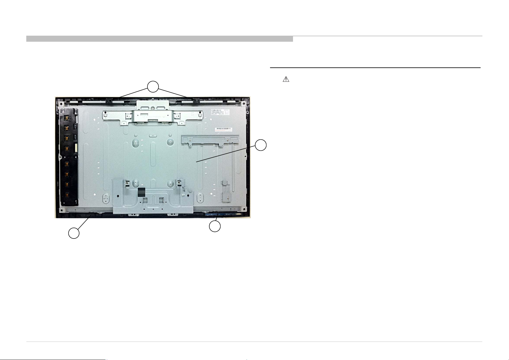
1-1. KLV-32NX520
1-1-5. PANEL SUPPORT, H BOARD, LCD PANEL AND BEZEL ASSY
20
DISASSEMBLY AND PARTS LIST
REF. No . PART No . DES CRIPT IO N M ARK
20 X-2581-453-1 PANEL, SUPPORT(A) A SSY
21 1-811-377-11 LCD PANEL (A32VC)
22 1-857-898- 11 MOUNTED PWB H
23 A-1817-892-A GLASS ASSY
21
23
KLV-32/40NX520(IN/VN)
22
14
Page 15
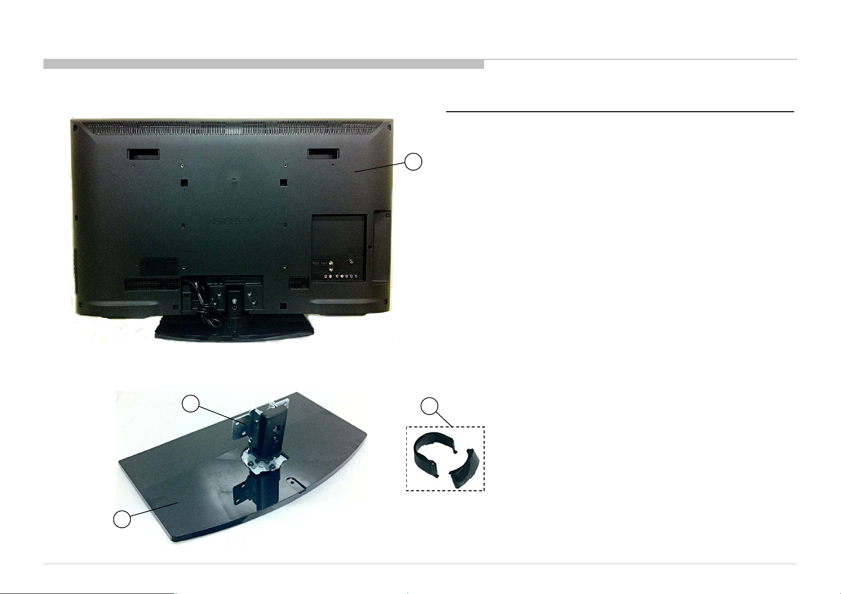
1-2. KLV-40NX520
DISASSEMBLY AND PARTS LIST
1-2-1. REAR COVER ASSY AND STAND BLOCK
1-2-2. NECK COVER, NECK AND BASE ASSY
1
REF. No .
PART No. DESCRIPTION
1 4-274-583-01 REAR COVER (RW40)
2 X-2546-340- 1 NECK (ML2) ASSY
3 X-2580-826-1 BASE (ML7) ASSY
4 X-2546-540- 1 COVER (M3) ASSY
MARK
3
KLV-32/40NX520(IN/VN)
2
4
15
Page 16
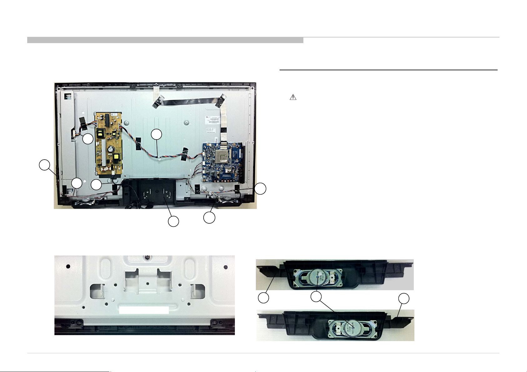
1-2. KLV-40NX520
DISASSEMBLY AND PARTS LIST
1-2-3. SWITCH UNIT, HARNESS AND SIDE BRACKET
7
5
6
8
9
10
12
1-2-4. SP BRACKET AND SPEAKER
REF. No . PART No . DES CRIPT IO N MARK
5 1-489-627-11 SWITCH UNIT
6 * 1-910-103-46 CONNECTOR ASSY 40 FHD 4P
7 * 1-910-103-49 CONNECTOR ASSY 40 FHD 14P
8 * 1-838-984-11 POWER SUPPLY CORD (WI TH CORE)
9 * 1-910-103-50 CONNECTOR ASSY 40 FHD 16P
11 * 1-910-103- 48 CONNECTOR ASSY 40 FHD 12P
12 * 1-910-103- 47 CONNECTOR ASSY 40 FHD 6P
13 4-267-048-02 BRACKET, SP R (RW40)
14 1-858-341-11 LOUDSPEAKER (4X10CM)
15 4-267-047-02 BRACKET, SP L (RW40)
11
KLV-32/40NX520(IN/VN)
BOTTOM FRAME
13
14
15
16
Page 17
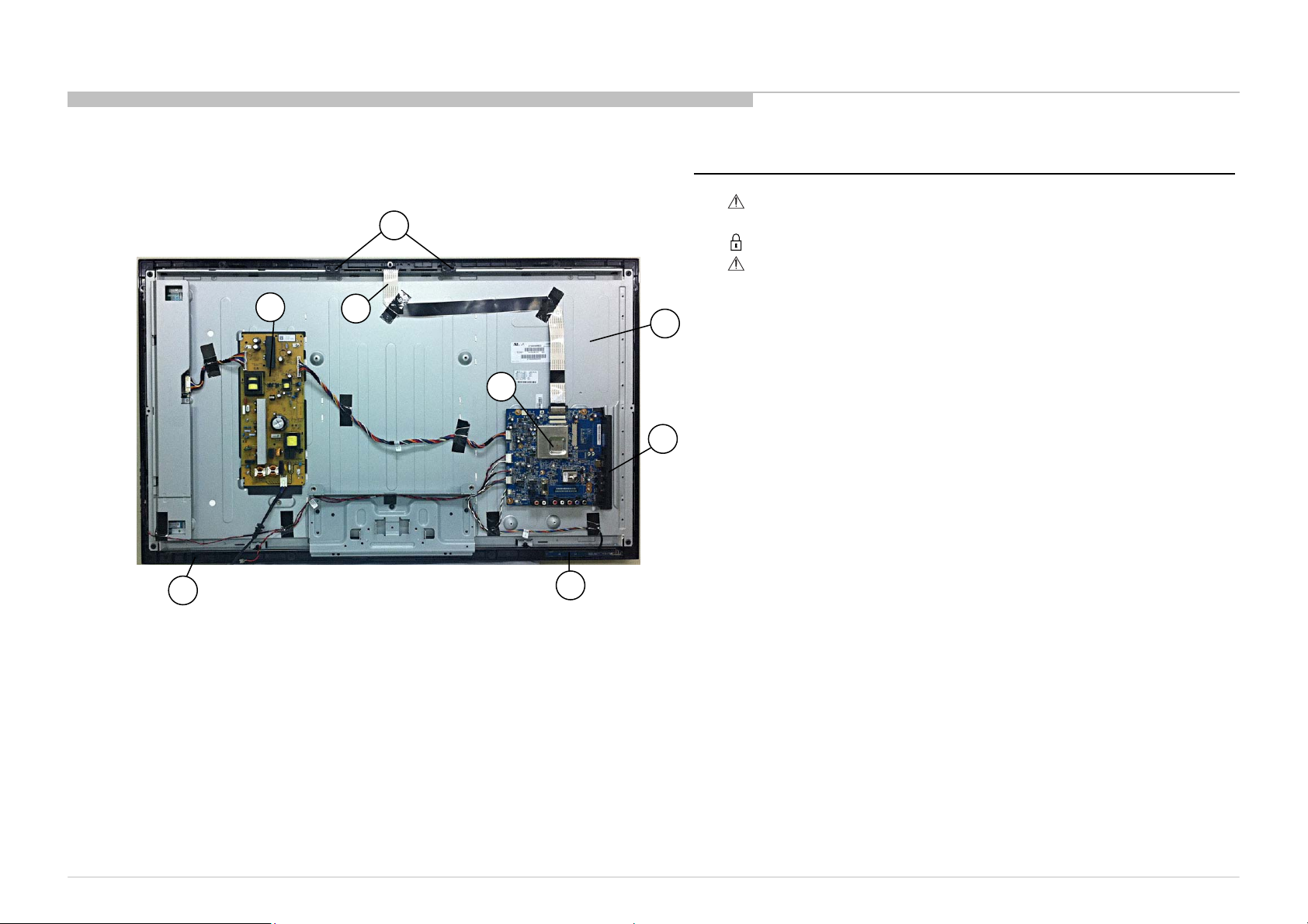
1-2. KLV-40NX520
DISASSEMBLY AND PARTS LIST
1-2-5. PANEL SUPPORT, G14 BOARD, A BOARD, H BOARD,
LCD PANEL AND BEZEL ASSY
16
17
23
18
19
22
REF. No .
20
21
PART No. DESCRIPTION
16 X-2581-453-1 PANEL, SUPPORT(A) ASSY
17 1-474-310-21 STAT IC CONVERTER (TV)-G14
18 * 1-910-103- 26 CONNECTOR ASSY 40 FFC FHD
19 1-857-896- 21 MOUNTED PWB A
20 1-811-329-11 LCD PANEL (S40ESP)
21 4-266-615-01 BRACKET, SIDE (PAA) (GW)
22 1-857-898- 11 MOUNTED PWB H
23 A-1817-893-A GLASS ASSY
MARK
KLV-32/40NX520(IN/VN)
17
Page 18
DISASSEMBLY AND PARTS LIST
1-3. OTHER PART
1-3-1. MISCELLANEOUS 1-3-2. ACCESSORIES
PART No . DESCRI P T I ON MARK PART No . D ESCRI P T I ON MARK
* 4-269-410-01 CUSHION, UPPER (RW32) (KLV-32NX520) 1-489-460-11 REM O TE COM MA NDER (RM-G A020)
* 4-269-411-01 CUSHION, LOWER (RW32) (KLV-32NX520) 1-822-631-11 PLUG CONVERSION ADAPTOR (INDIA )
* 4-267-938-01 CARTON, INDIV IDUAL (KLV-32NX520) 4-270-477-14 MANUAL, INSTRUCTION
4-270-477-23 MANUAL, INSTRUCTION (VIE TNAM)
* 4-269-412-01 CUSHION, UPPER (RW40) (KLV-40NX520) 4-270-477-73 MANUAL, INSTRUCTIO N (VIET NAM)
* 4-269-413-01 CUSHION, LOWER (RW40) (KLV-40NX520)
* 4-267-939-01 CARTON, INDIV IDUAL (KLV-40NX520)
KLV-32/40NX520(IN/VN)
18
Page 19
SEC 2. ADJUSTMENT
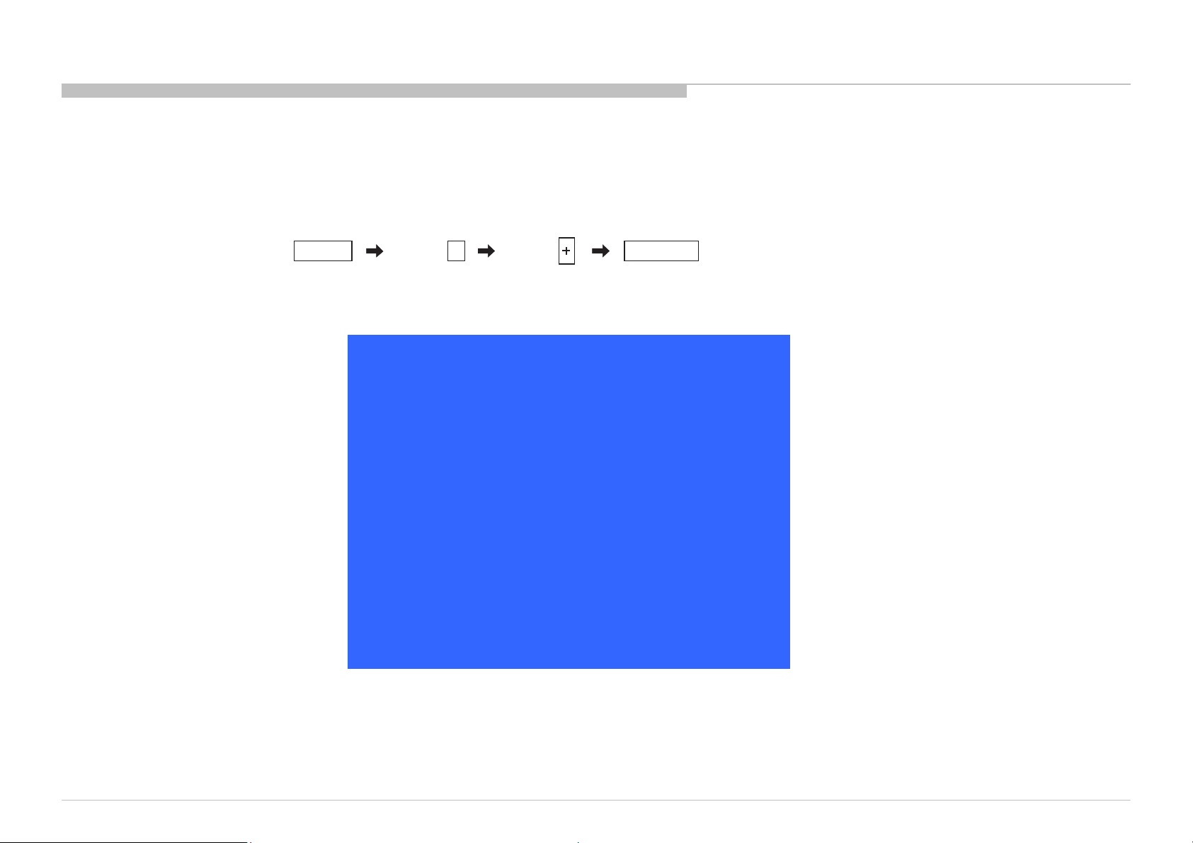
HOW TO ENTERING SERVICE MODE
1) Turn on the main power switch to place this set in standby mode.
2) Press the buttons on the remote commander as follows, and entering service mode.
3) Service mode display.
Info TV POWERChannel Volume
StatusInformation >>
Selfdiagnosishistory >>
PanelSelection <[ SONY_WXGA_32_2]>
NO_SIGNAL_MUTE <[ Off ]>
TUNINGSYSTEM <[ AUTO ]>
LVDSSpectrum(%o) <[ 20 ]>
LowofHPD <[ 5 ]>
5
ServiceMode
[</>]Set[Home]Exit
KLV-32/40NX520(IN/VN)
19
Page 20
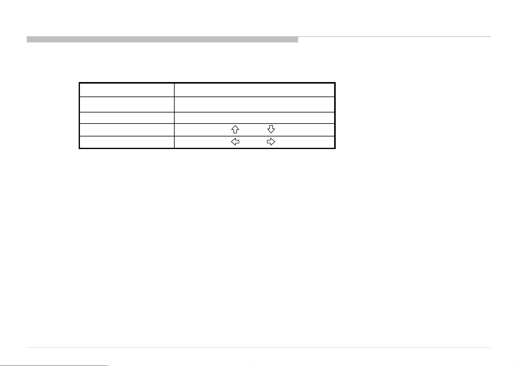
4) How to use the remote commander.
ADJUSTMENT
Function
Adjustment Item up / down
Data Value up / down
5) After entering service mode, then turn off the power switch.
The flow of control
<Info><5><Vol Up><Power>Service mode on
<Other> / <Power off + on>Service mode off
/
/
KLV-32/40NX520(IN/VN)
20
Page 21
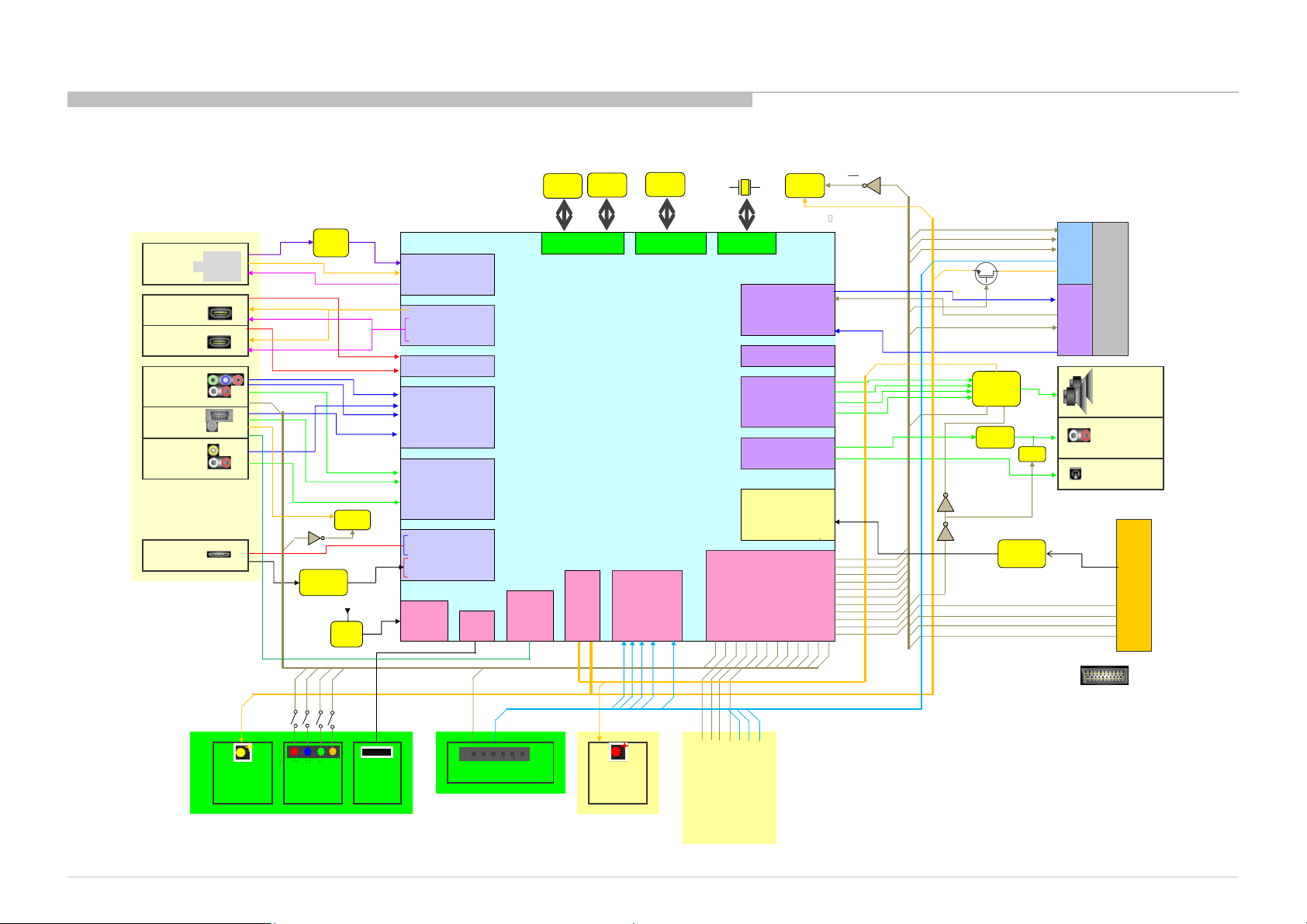
SEC 3. DIAGRAMS
3-1. BLOCK DIAGRAM
3-1-1. BLOCK
RF
HDMI1
HDMI2
Video1
Comp1
PC
Video2
(Side)
USB
AV_COMP_SEL
OSDA0/OSCL0
Light
Sensor
SAW
Filter
EEPROM
WC
USB Current
Limitter
3.3STBY
Keep
RST
100ms
or more
IC
LED
HBoard
ADCINN/P_DEMOD
TUNER_DATA/CLK
IF_AGC
HDMI_SDA0/SCL0
HDMI_HPD0/1/2
PWR5V_0/1/2
HDMI_CEC
RX0_0/1/2/C
RX1_0/1/2/C
CVBS1
CVBS3
Y0P/PB0P/PR0P/SOY0
Y1P/PB1P/PR1P/SOY1
BP/GP/RP/VSYNC/HSYNC
AIN1_L/R_AADC
AIN2_L/R_AADC
AIN3_L/R_AADC
AIN6_L/R_AADC
USB_DP
USB_DM
USB_PWR_EN0
USB_PWR_ERR
Reset
IR
IR
OIRI
Po
wer
Key
Key
Pad
Key Pad
Demod
HDMI
Contro
HDMI
Reciever
Analog
Video In
Analog
Audio In
USB
Interface
UART
DDR
512Mbit
RA*/RBA*/RDQ
RDQM*
DRAM
Interface
I2C
OSDA0/
OSCL0
OSDA1/
OSCL1
OSDA0
/OSCL0
DDR
512Mbit
Servo ADC
12V_S12V
Temp
Sensor
Flash
512Mbit
PDD*/etc
Nand Flash
Interface
PWM Audio Out
ADIN5_SRV
ADIN4_SRV
ADIN3_SRV
ADIN2_SRV
PA
Key
NEL
_A
Pad
anc
_SE
MP
L
Analog
Video Out
Power
GPIO
Bal
er
Err
12V_SW
Balancer Error
12V_Audio
Audio AMP Error
T-Con Error
5V Det
Error
Detction
Crystal
crystal in
crystal out
CLK/Crystal
LVDS
IIS
SPDIF
PTSI_CLK
GPIO0
GPIO1
OPCTRL0
GPIO2
OPCTRL1
OPCTRL2
GPIO3
GPIO4
HDMI_HPD2
HDMI_SDA2
GPIO5
HDMI_SCL2
GPIO6
GPIO7
EEPROM
128Kbit
OSDA0/OSCL0
Tx even/odd
LVDS_CTRL1
LVDS_CTRL2
VSYNC
AOMCLK
AOBCK
AOLRCK
AODATA0
AL0/AR0_PWMDAC
ASPDIF
AVDD12(1.2V)
AVDD33(3.3V)
VCCK(1.0V)
VCC2IO(1.8V)
PTSI_CLK
PTSI_VALID
PTSI_SYNC
PTSI_D0 ? D7
WS
OSDA0/OSCL0
TCON_RDY
LVDS_SEL(FFC:0, othre:1)
V_Sync
Audio
AMP
RESET_AMP
AMP_MUTE
Buffer
DD & LDO
DDC_LUT0
DDC_LUT1
DDC_LUT2
PANEL_SEL
Mute
POWER ON ENABLE
Co
ntr
Pa
ol
ne
T?
Co
AC OFF DET
LVDS POWR ON
Inverter Dimming
Speaker
Out
Audio
Out
SPDIF
Po
we
r /
Inv
ert
er
KLV-32/40NX520(IN/VN)
21
Page 22
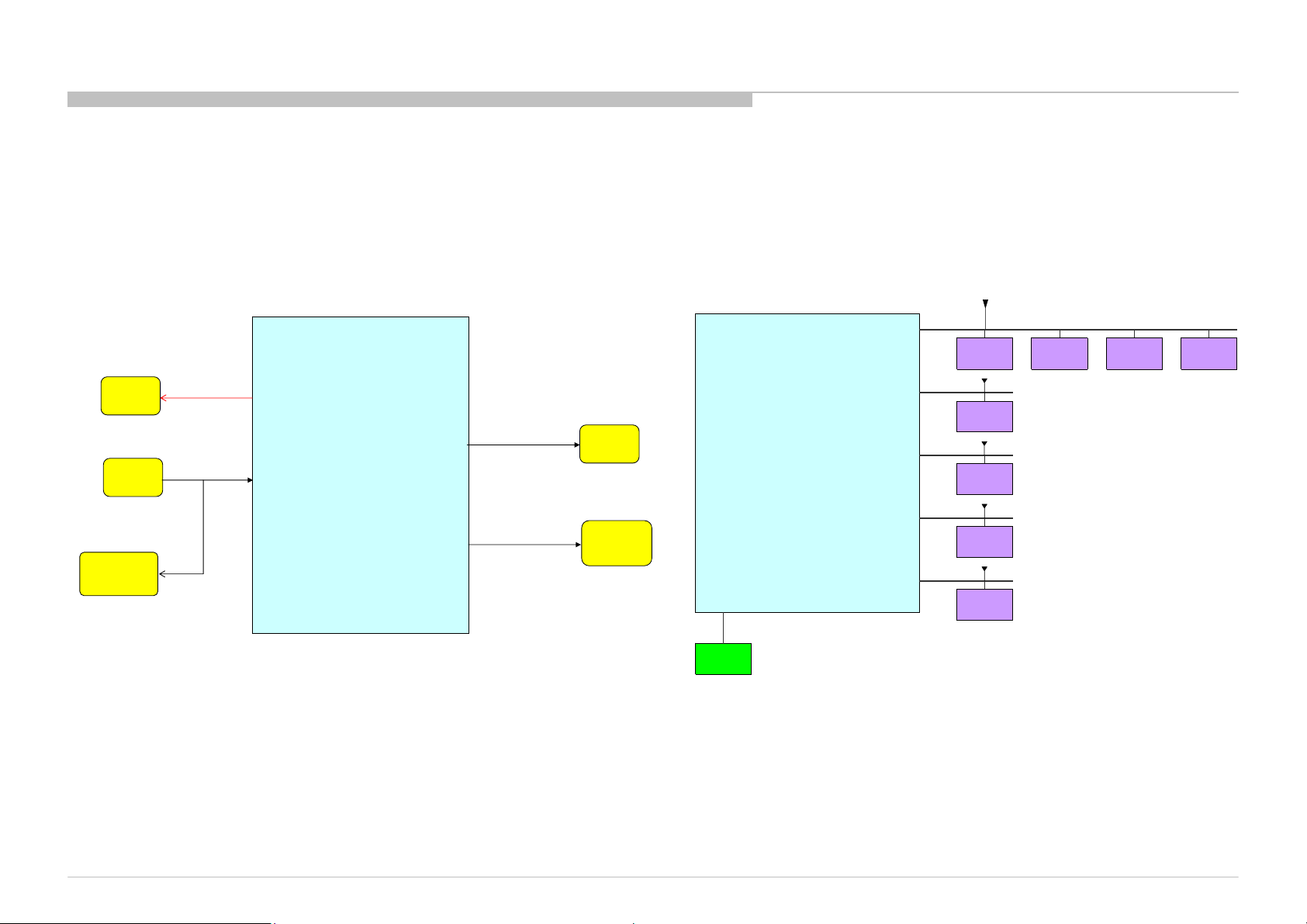
3-1. BLOCK DIAGRAM
3-1-2. RESET/I2C & UART
DIAGRAMS
3V3_SW
EEPRO
Reset
Flash
512Mbit
WS#
WP
ORESET#
MT5388
USB_PWR_EN
GPIO_7
EN
RESET_AMP
USB
Audio
AMP
MT5388
U0TX
U0RX
D-SUB15
For Debug
TUNER_CLK/TUNER_DATA
HDMI_SCL0/HDMI_SDA0
HDMI_SCL1/HDMI_SDA1
UART
OSDA0/OSCL0
OSDA1/OSCL1
3V3_SW
Audio AMP
5V_TUNER
Tuner
3V3_SW
HDMI1
3V3_SW
HDMI2
Temp
Sensor
I2C
Light
Sensor
T-ConEEPROM
KLV-32/40NX520(IN/VN)
22
Page 23
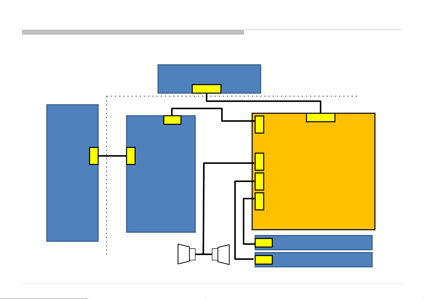
3-2. CONNECTOR DIAGRAM
3-2-1. KLV-32NX520
CN6401
DIAGRAMS
T-CON Board
Panel
CN2
CN202
Inverter
KLV-32/40NX520(IN/VN)
CN6402
G13
Power Board
CN8156
CN13
CN17
Main board
CN9101 IR board
Key Pad board
23
Page 24
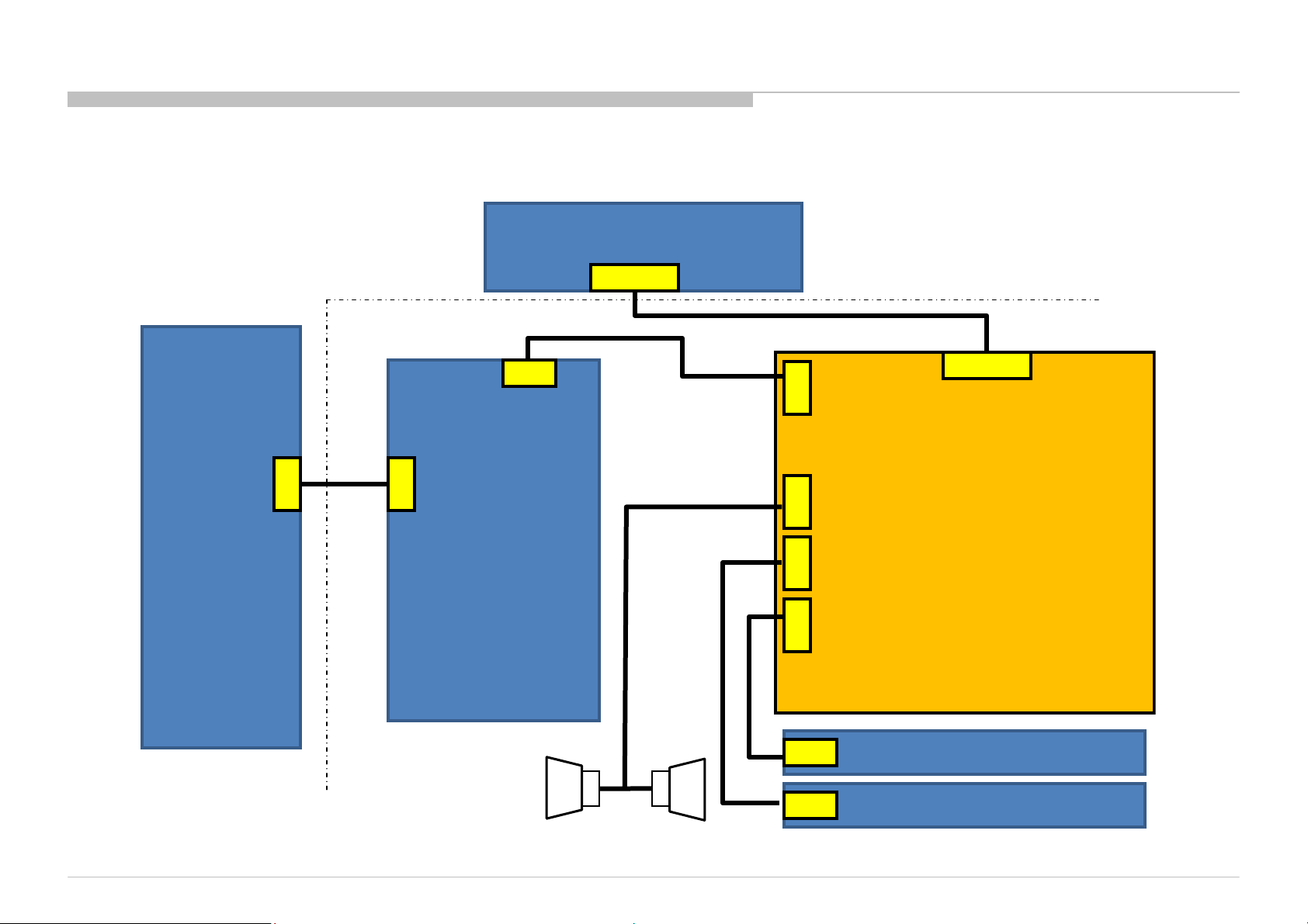
3-2-2. KLV-40NX520
CN6401
DIAGRAMS
T-CON Board
Panel
CN2
CN202
Inverter
KLV-32/40NX520(IN/VN)
CN6402
G14
Power Board
CN8156
CN13
CN17
Main board
CN9101 IR board
Key Pad board
24
Page 25
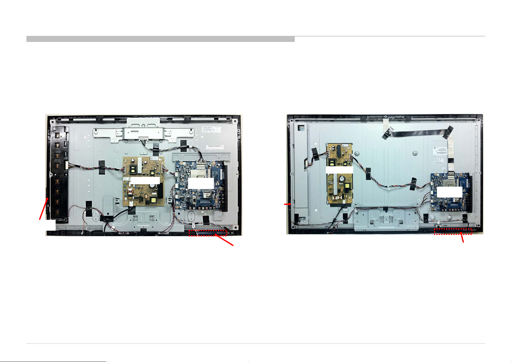
3-3. CIRCUIT BOARDS LOCATION
KLV-32NX520 KLV-40NX520
DIAGRAMS
G14Board
Switch Unit
KLV-32/40NX520(IN/VN)
G13 Board
A Board
Switch Unit
H Board
A Board
H Board
25
Page 26

END
9-888-406-01
KLV-32/40NX520(IN/VN)
Sony EMCS Corporation
Tokai TEC Inazawa Site
English
2010BL08-Data
Made in Japan
© 2010. 02
26
 Loading...