

Page 1

HISTORY INFORMATION FOR THE F OL LOWING MANUAL:
SERVICE MANUAL (COMMON)
Version Date Subject
1 01/2014 1st Issue.
ITC3 CHASSIS
Segment: ME
2 05/2014 i) Add Software Update Procedure ( pg 76 )
ii) Correction on board name ( pg 8 , 9 , T/shooting section pg 10 ~ 51 )
LCD TV
9-888-148-02
For SM - Uni q u e , pleas e ref er :
9-888-148-Ax ( America )
9-888-148-Cx ( China)
9-888-148-Ex ( Europe )
9-888-148-Px ( Pan Asia )
Page 2

SERVICE MANUAL (COMMON)
ITC3 CHASSIS
Segment: ME
LCD TV
Page 3

MODEL LIST
THIS SERVICE MANUAL CONTAINS COMMON INFORMA TION FOR BELOW RE GIONS AND MODELS:
REGION
ASIA CHINA AMERICA EUROPE
MODEL
KLV-28R412B
KLV-32R412B KDL-32R430B KLV-40R472B
KDL-40RM10B
KLV-48R472B
KLV-32R422B KDL-32R433B KLV-40R482B KDL-48R470B
KLV-32R426B KDL-32R435B KDL-40R450B KDL-48R473B
KLV-32R482B KDL-32RM5B KDL-40R453B KDL-48R475B
KDL-32R410B KDL-40R455B KDL-48R480B
KDL-32R413B KDL-40R470B KDL-48R485B
KDL-32R415B KDL-40R473B
KDL-32R420B KDL-40R475B
KDL-32R423B KDL-40R477B
KDL-32R424B KDL-40R478B
KDL-32R425B KDL-40R480B
KDL-32R427B KDL-40R483B
KDL-32R428B KDL-40R485B
3
Page 4

......……………....................................
Caution About the Lithium Battery……………. .... ...... .... ..... ...... ... ...... ..... .
........................…………….........................................
..........................................................................................
Overview of Co ntro l Button s ............ ... .. .... .... .. ... .... .. ... .... .. .... ... .. .... .... . ....
……….....................................................................
HDMI……………..……...…………………………………………………….
IR……………………………………………………………………………….
………………………………………………………..
TABLE OF C ON TEN TS
.....................................................................
Accessing Software Vers ion.................... ……….… ……………… ……
Acces sin g Mode l Name E dit........ .. .... .... . .... .... .. ... .... .. .... ... .. .... .... . .... ....
.........................................................................
Section Title Page
1. SAFETY NOTES
1-1.
1-2.
1-3.
1-4.
1-5.
1-6. How to Find a Good Earth Ground………………………………………… 6
1-7. Lead Free Information….…………………………………………………… 7
1-8.
2. SELF DIA GNOSTIC FUN CTION
2-1.
2-2.
2-3.
2-4.
2-5.
3. TROUBL E SHOOTIN G
3-1.
3-2.
3-3.
3-4.
3-5.
3-6.
3-7.
3-8. MHL…………………………………………………………………………. 39
3-9.
3-10. Ethernet………………………………………………………………………. 59
3-11.
3-12.
3-13.
Warnings and Caution………………………………………………………. 5
Caution Handling of LCD Panel
Safety Check Out
Leakage Test
Handling the Flexible Flat Cable (FFC)……………………………………. 7
LED Display Control
LED Pattern………………........................................................................ 8
Standby LED Error Display…………………………………………………. 8
Triage Chart ............................................................................................ 9
General..................................................................................................... 10
No Power…….……………………………………………………………….. 10
Standby LED Blinking....…………............................................................ 13
No Picture................................................................................................. 21
Audio.............................…………………………………………................. 23
Video Problem.......................................................................................... 31
Tuner…………………………………..……………………………………… 42
Switch Un it Buttons…………….……………………………………………. 51
Wifi……………………
5
6
6
6
8
8
38
50
52
Section Title Page
4. SERVICE ADJUSTMENTS
4-1.
4-2.
4-3. Accessing Self Diagnos tic History……………………………… ..…….. 56
4-4.
4-5.
4-6.
5. DIAGRAMS
5-1.
5-2.
5-3. Connector Diagram ………………………………………...................... 70
Accessing Service Mode
Accessing Self Diagnostic Menu………………………………………... 56
Accessing Serial Number Edit……………….………………………….. 57
Circuit Board Location
Block Diagram...................................................................................... 62
Please refer Service Manual – Unique for below information :
-Safety Warnings
-Wire Dressing
55
55
58
60
-Circuit Board Location
-Disassembly and Exploded View.
4
Page 5
SECTION 1
SA FETY NOTES
ITC3 CHASSIS
R410/412/413/420/422/423/424/425/426/427/428/430/433/435/
450/453/455/470/472/473/475/477/478/480/483/485/M5/M10B
1-1. Warn ings and Caution
1) These servicing instructions are for use by qualified service personnel only.
2) To reduce the risk of electric shock, do not perform any servicing other than
that contained in the operating instructions unless you are qualified to do so.
3) An isolation transformer should be used during any service to avoid
Possible shock hazard, because of live chassis. The chassis of this receiver is
directly connected to the ac power line.
4) Be sure to follow these guidelines to protect your property and
avoid causing serious injury :
• Carry the TV with an adequate number of people; larger size TVs require
two or more people.
• Correct hand placement while carrying the TV is very important for
safety and to avoid damages.
5) Components identified by shading and mark on the exploded views,
and in the parts list are critical for safe operation. Replace these
components with Sony parts whose part numbers appear as shown in this
manual or in supplements published by Sony. Circuit adjustments that are
critical for safe operation are identified in this manual. Follow these
procedures whenever critical components are replaced or improper
operation is suspected.
!
1-2. Caution Handling of LCD Panel
When repairing the LCD Panel, make sur e you are grounded with a wrist band.
When repairing the LCD Panel on the wall, the panel must be secured usi ng the
4 mounting hol es on the rear cover .
1) Do not pr ess the panel or frame edge to avoi d the risk of electri c shock.
2) Do not scr atch or press on the panel w ith any sharp objects.
3) Do not leave the module i n high temperature or in areas of high humidi ty for
an extended per iod of time.
4) Do not expose the LCD panel to direct sunlight.
5) Avoid contact with water . I t may cause short ci rcu it within the module.
6) Disco nnect the AC power when replaci ng the backl ight ( CCF L) or
inverter cir cuit . (Hi gh voltage occur s at the inver ter ci rcui t at 650Vrms)
7) Always cl ean the LCD panel with a soft cloth mater ial .
8) Use care when handli ng the wir es or connectors of the inver ter ci rcui t.
Damaging t he wir es may cause a short cir cuit.
9) Protect the panel from ESD to avoid damaging the elect roni c circuit (C-MOS).
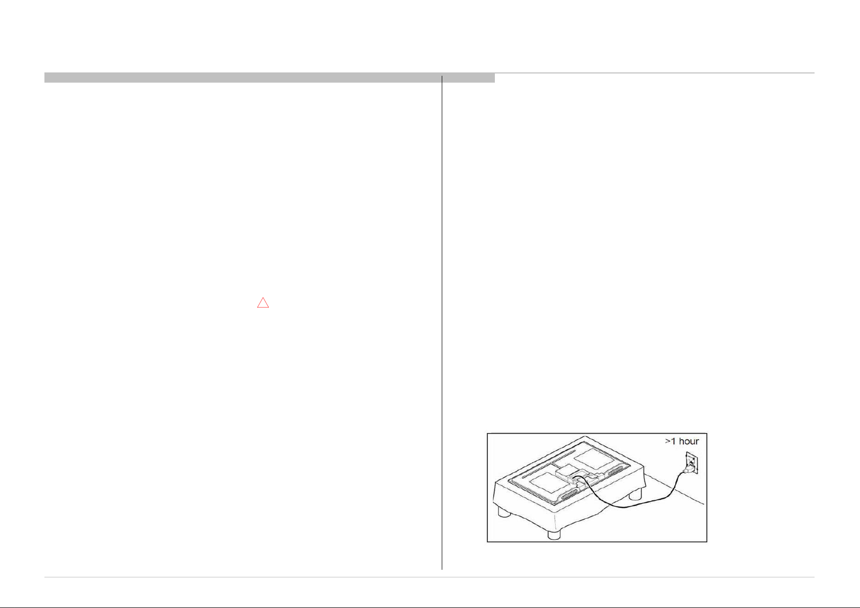
10) Dur i ng the r epai r , DO NOT leave the Power O n or Bur n-i n period for more
than 1 hour w hil e the T V i s face dow n on a cloth.
Figure 1. TV is faced down on a cloth during repair.
5
Page 6

Safety Notes
1-3. Caution About the Lithium Battery
1) Danger of explosion if battery is incorrectl y replaced. Replace only with
the same or equivalent type.
2) Outer case broken battery shoul d not contact to water.
1-4. Safety Check-Out
After correcting the original service problem, perform the following
safety checks before releasing the set to the customer:-
1) Check the area of your repair for unsoldered or poorly soldered
connections. Check the entire board surface for solder splashes and bridges.
2) Check the inter board wiring to ensure that no wires are pinched or
contact high-wattage resistors.
3)Check all control knobs, shields, covers, ground straps and mounting
hardware have been replaced. Be absolutely certain you have replaced all
the insulators.
4) Look for unauthorized replacement parts, particularly transistors that
were installed during a previous repair. Point them out to the customer and
recommend their replacement.
5) Look for parts which, though functioning show obvious signs of
deterioration. Point them out to the customer and recommend their
replacement.
6) Check the line cords for cracks and abrasion. Recommend the
replacement of any such line cord to the customer.
7) Check the antenna terminals, metal trim, metalized knobs, screws and all
other exposed metal parts for AC leakage. Check leakage test as described
next.
8. For safety reasons, repairing the Power board and/or Inverter board is
prohibited.
1-5.Leakage Test
The AC leakage from any exposed m etal par t to earth ground and from all
exposed metal par ts to any exposed metal part having a retur n to chassi s must
not exceed 0.5mA (500 micr oamperes) .
Leakage cu rrent can be measur ed by any one of the three m ethods:-
1) A comm erci al leakage test er such as the SIM P SON 229 or RCA WT540A.
Follow the manufacturers instr uctions to use those instruct ions.
2) A battery-operate d AC milliampmeter The DATA PRECISI ON 245 digital
multimeter is suitable for this job.
ITC3 CHASSIS
R410/412/413/420/422/423/424/425/426/427/428/430/433/435/
450/453/455/470/472/473/475/477/478/480/483/485/M5/M10B
3) Measu ring the volt age dr op across a resi stor by means of a VOM or battery
operated AC voltmeter. The 'li mi t' indication is 0.75V so analog m eters m ust
have an accurate low volt age scale. T he SIM PSON' S 250 and SANWA SH63TRD are exampl es of passi ve VOM s that are sui table. N early all battery
operated digi tal mul timeter that have a 2 VAC range are sui table.
(see Figur e 2.)
Figure 2. AC voltmeter to check AC leakage
1-6. How to Find a Good Earth Ground
1) A cold-water pi pe is a guaranteed ear th ground; t he cover-pl ate retaini ng
screw on most AC outlet boxes i s also at earth ground.
2) If the retaining scr ew is to be used as your earth ground, veri fy that it is at
ground by measuring the r esi st ance between it and a col d-w ater pi pe with an
ohmmeter. T he readi ng should be zer o ohms.
3) I f a cold-w ater pi pe is not accessi ble, connect a 60- to 100-watt t roublelight (not a neon lamp) between the hot side of the recept acle and the
retaining scr ew. Tr y both slots, if necessa ry, to locate the hot si de on the line;
the l am p shoul d l i ght at normal brilli ance i f the screw is at ground potential
(see Figur e 3).
Figure 3. Checking for earth
ground.
6
Page 7
Safety Notes
ITC3 CHASSIS
R410/412/413/420/422/423/424/425/426/427/428/430/433/435/
450/453/455/470/472/473/475/477/478/480/483/485/M5/M10B
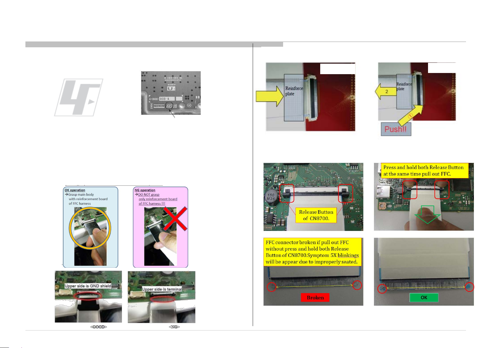
1-7. Lead Free Information
The circui t boards used i n these model s have been pr ocessed using Lead
Free Solder. The boards ar e identified by the LF logo loca ted close to the
board designation.
The servici ng of these boards r equires special precautions. It is strongly
Figure 4: LF Logo
recommended to use Lead Free Solder materi al in order to guarantee optimal
quality of new solder joi nts.
1-8. Handling the FLEXIBLE FLAT CABLE (FFC)
When you insert / pull out FFC, please grasp a reinforcement board and main
body of FFC.
Figure 5: LF logo on circuit board
Pleas e hol d rei nfor ce men t b oard an d
plunge it to depths.
Main Board
< Insertion>
Please pull out FF C while pushing the
but ton of both end s at the s ame tim e.
Main Board
<Pull out>
7
Page 8
Self Diagnostic Function
SECTION 2
SELF DIAGNOSTIC FUNCTION
ITC3 CHASSIS
R410/412/413/420/422/423/424/425/426/427/428/430/433/435/
450/453/455/470/472/473/475/477/478/480/483/485/M5/M10B
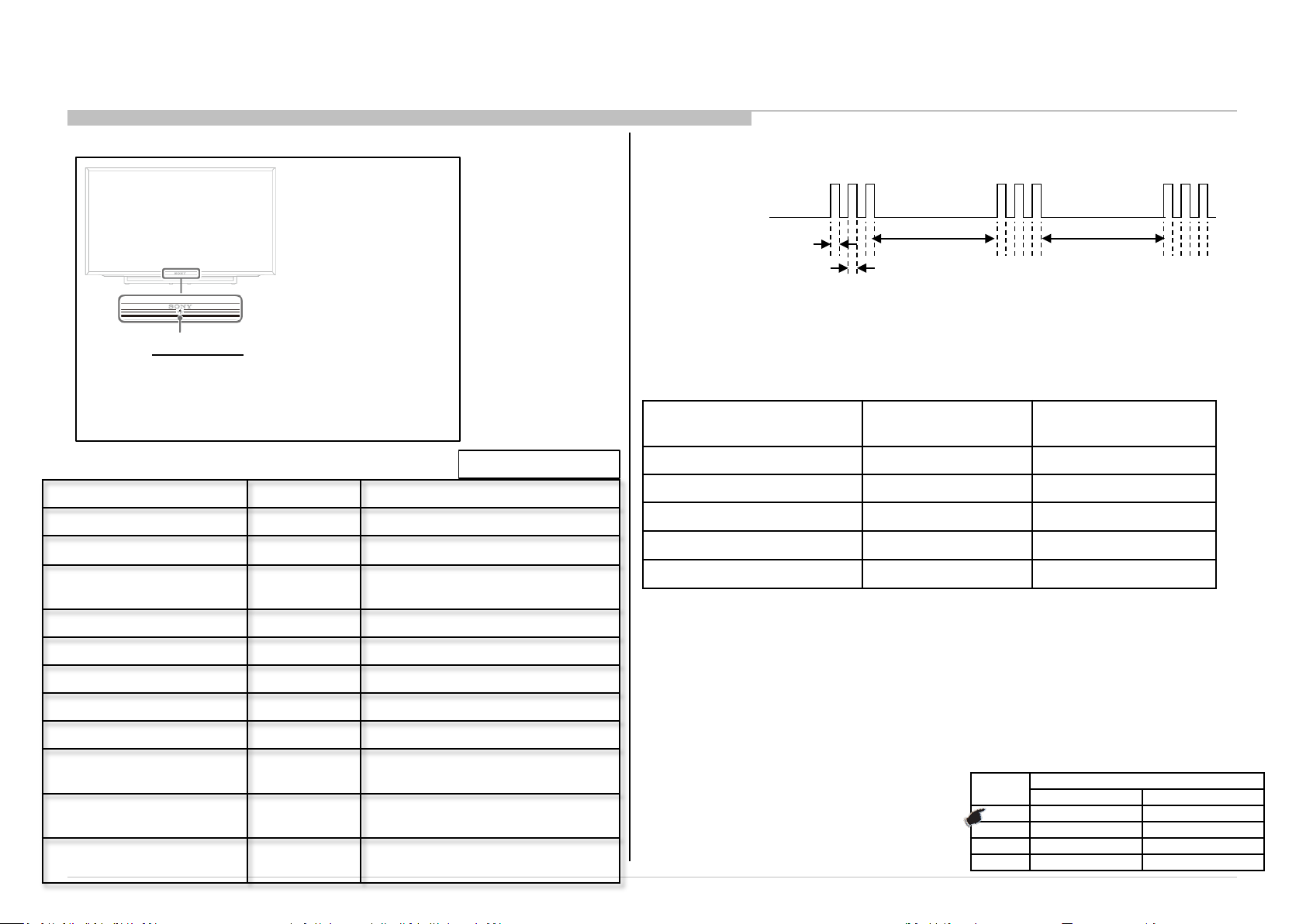
2-1. Overview of Control Buttons
LED Indicator
• Lights up in green when you select “Picture Off”.
• Lights up in amber when you set the timer or
“Photo Frame Mode”.
• Lights up in green when the TV is turned on.
• Flashes while the remote is being ope rated.
2-2. LED Display Control
Status LED Colour Remarks
Power Off ( AC Off and *1) OFF *1 power switch off (by touch button)
Power On Green
Standby( by remote control
off only )
OFF
Amber = Red + Green
2-3. LED Pattern
When safety shutdown occurs, Standby LED display reports the cause by using the lightning
0.5sec
.
3.0sec 3.0sec
0.5sec
patterns as indicated below
Example: The figure above shows LED display when SHUTDOW N is caused by Audio
Error. It repeats flashing f or a specified numb er of times in 0.5sec/c ycl e and has a 3 sec ond s in ter val of lighting
off. Pleas e not e that a 3 s econd s in ter val of light ing off is f ixed r egar dle ss of abnor ma l st ate t ypes.
2-4. Standby LED Error Display
The Number of Standby LED
(RED blinking)
2 Main Power Error AC adapter Error
3 Audio Error B* board Error
4 Panel Power Error B* board Error
5 Panel I2C COMM Error B* or Source board Error
6 Backlight Error B* board Error
Dete ct ion Ite ms Board Error Item
Picture Off Green
Set "Sleep Timer" Amber
Set " On T ime r” ( Powe r On ) Amber
Set "On Timer”( Standby ) Amber
Picture Frame Amber
Failure Red Blinking
Error of panel ID
Software Updating
6
Amber/Green
Blinking
Amber
Blinking
The number of LED blinking indicates
cause of failure.
Blinking:0.5sec Amber/ 0.5sec Green
Blinking: 1sec O n / 1sec Off
B*Board Type:
Size
PAN ASIA, CHINA EUROPE, AMERICA
28” BIS 32” BIS BIL
40” BIS BIL
48” BIS BIL
B* Board Type
8
Page 9
Self Diagnostic Function
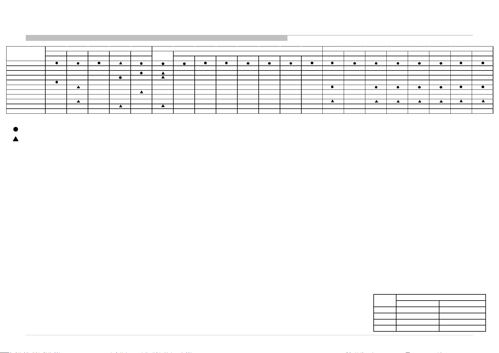
2 3 4 5 6 Tuner USB Video Component HDMI MHL SCART Main Spe aker HP Video Component Tuner HDMI SCART US B
B-Board
HIL Board
Light S ource Board
Open Cell
AC Adaptor
Speaker Unit
LS Harne ss
Main Harness
Speaker Harness
FFC Cable
Blinking
No Sound
No P icture
UI OK
UI N G
2-5. Tri age C hart
Most likely defective part
Secondary possible defective part
ITC3 CHASSIS
R410/412/413/420/422/423/424/425/426/427/428/430/433/435/
450/453/455/470/472/473/475/477/478/480/483/485/M5/M10B
B*Board Type:
Size
PAN ASIA, CHINA EUROPE, AMERICA
28” BIS 32” BIS BIL
40” BIS BIL
48” BIS BIL
B* Board Type
9
Page 10
Troubleshooting
3-1. General
SECTION 3
TROUBLESHOOTING
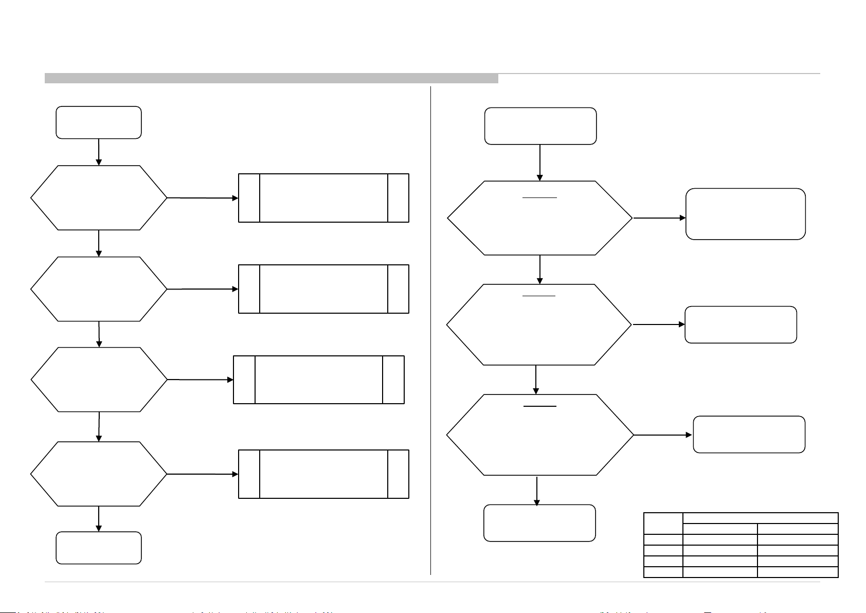
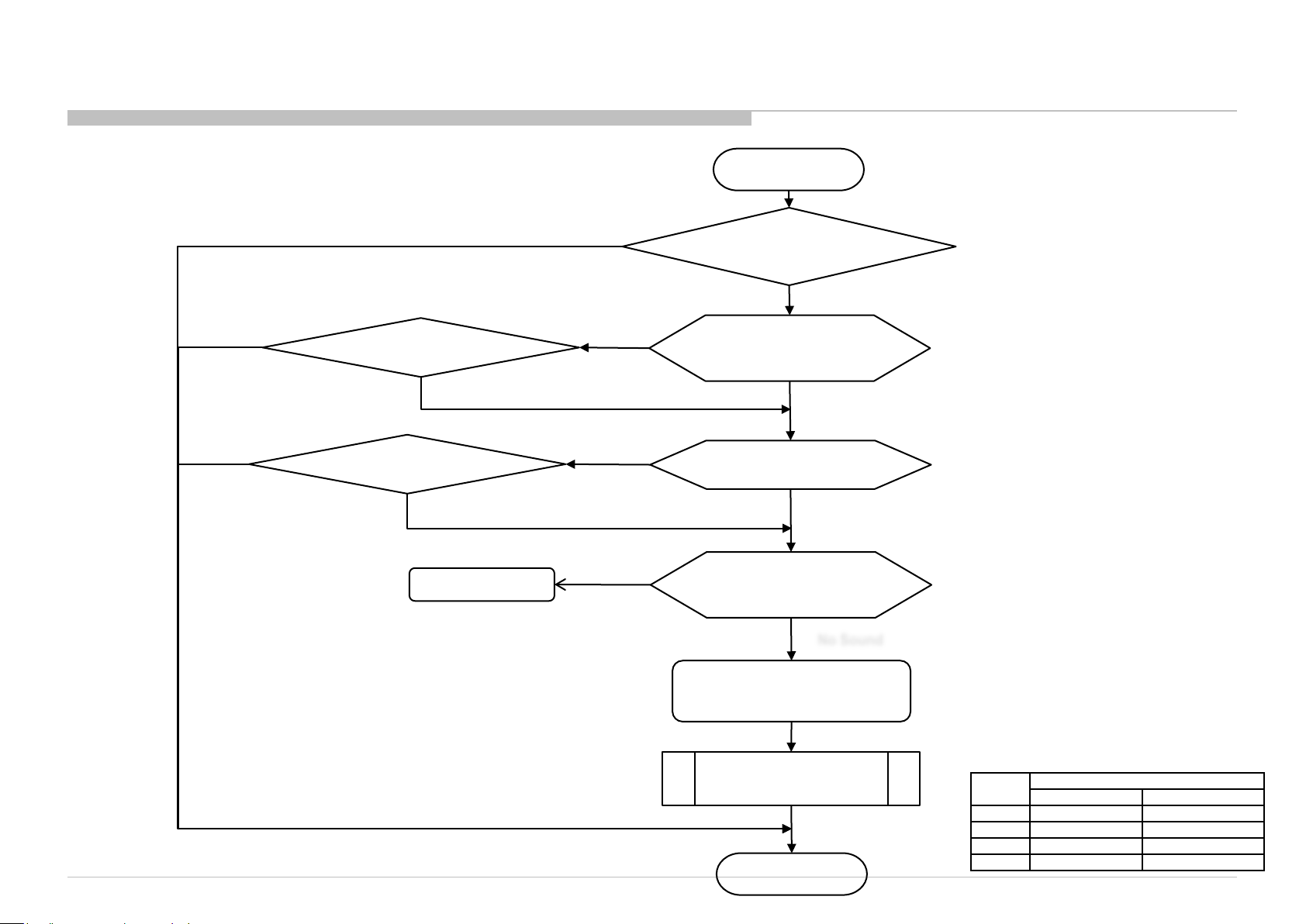
3-2. No Power
ITC3 CHASSIS
R410/412/413/420/422/423/424/425/426/427/428/430/433/435/
450/453/455/470/472/473/475/477/478/480/483/485/M5/M10B
START
Does the Power Led
stay on when the
TV is switched on ?
Is the Standby Led
blink ?
Green & Amber
blink?
Is the Picture and
Sound OK ?
END
Open Detail
- No Power
Open Detail
- Standby LED Blink
- Panel ID Error
- Panel Not Supported
Open Detail
- Picture/Audio/Video
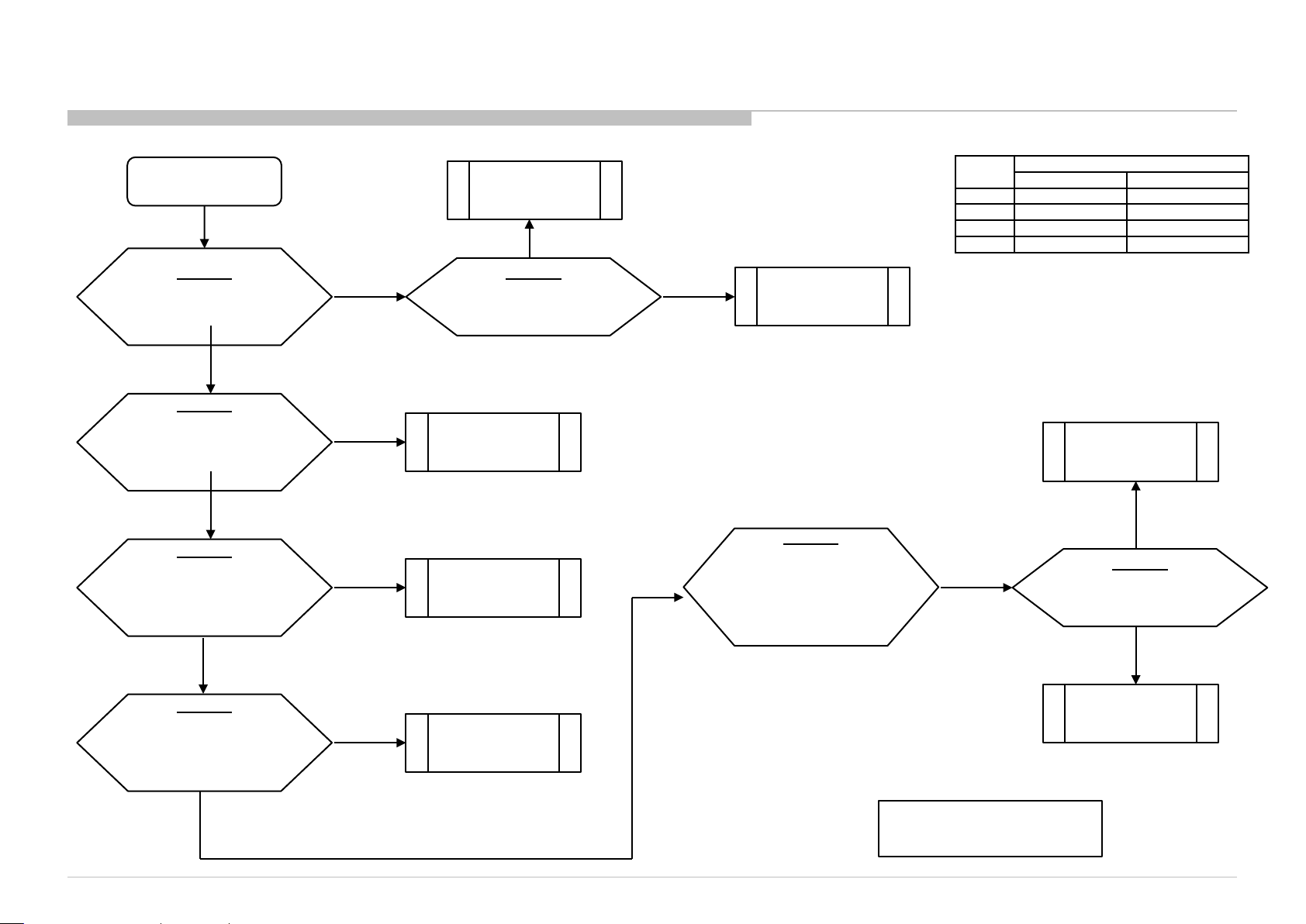
No Power
No
B-Board
Check DC voltage at
JL6001
19V - 19.5V?
No
Adaptor
Take out adaptor
and check the output voltage.
19V – 19.5V?
(Refer Figure 1)
No
Adaptor
Change adaptor
and recheck the output voltage.
19V – 19.5V?
(Refer Figure 1)
No
AC source
Yes
Yes
Yes
•See DDCON
Sheet
B-board
Adaptor
B*Board Type:
Size
PAN ASIA, CHINA EUROPE, AMERICA
28” BIS 32” BIS BIL
40” BIS BIL
48” BIS BIL
B* Board Type
10
Page 11
3-2. No Power
3-2-1. DD Con
B-Board
Check voltage at JL6003
Yes
B-Board
Check voltage at JL6000
Start
3.3V?
1.2V?
ITC3 CHASSIS
R410/412/413/420/422/423/424/425/426/427/428/430/433/435/
450/453/455/470/472/473/475/477/478/480/483/485/M5/M10B
B*Board Type:
Size
DDCON
OK
No
No
Change B-board
B-Board
Check fuse.
F6001 & F6002
No
Fuse
PAN ASIA, CHINA EUROPE, AMERICA
28” BIS 32” BIS BIL
40” BIS BIL
48” BIS BIL
B* Board Type
DDCON
Yes
B-Board
Check voltage at JL6002
1.5V?
Yes
B-Board
Check voltage at JL6005
5V?
Yes
No
No
Change B-board
Change B-board
B-Board
Check voltage at :
BIS JL6012.
BIL JL6007.
12V?
No
After checking, take note of
NG condition & change B board
OK
B-Board
Check Fuse .
F6003
No
Fuse
11
Page 12
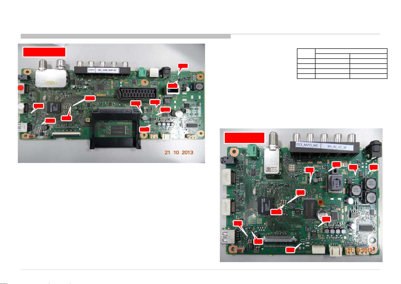
BIL BOARD
JL
60
06
JL
60
05
ITC3 CHASSIS
R410/412/413/420/422/423/424/425/426/427/428/430/433/435/
450/453/455/470/472/473/475/477/478/480/483/485/M5/M10B
B*Board Type:
Size
PAN ASIA, CHINA EUROPE, AMERICA
JL
60
01
28” BIS 32” BIS BIL
40” BIS BIL
48” BIS BIL
F6
00
1
JL
60
02
JL
60
00
JL
60
03
F6
00
2
F6
00
3
JL
60
07
BIS BOARD
B* Board Type
F
60
JL
60
03
JL
60
02
JL600
0
JL
60
06
JL
60
05
JL
60
12
02
F
60
03
F
60
01
JL
60
01
12
Page 13
3-3. Standby LED Blinking
3-3-1. 2 times blinking
ITC3 CHASSIS
R410/412/413/420/422/423/424/425/426/427/428/430/433/435/
450/453/455/470/472/473/475/477/478/480/483/485/M5/M10B
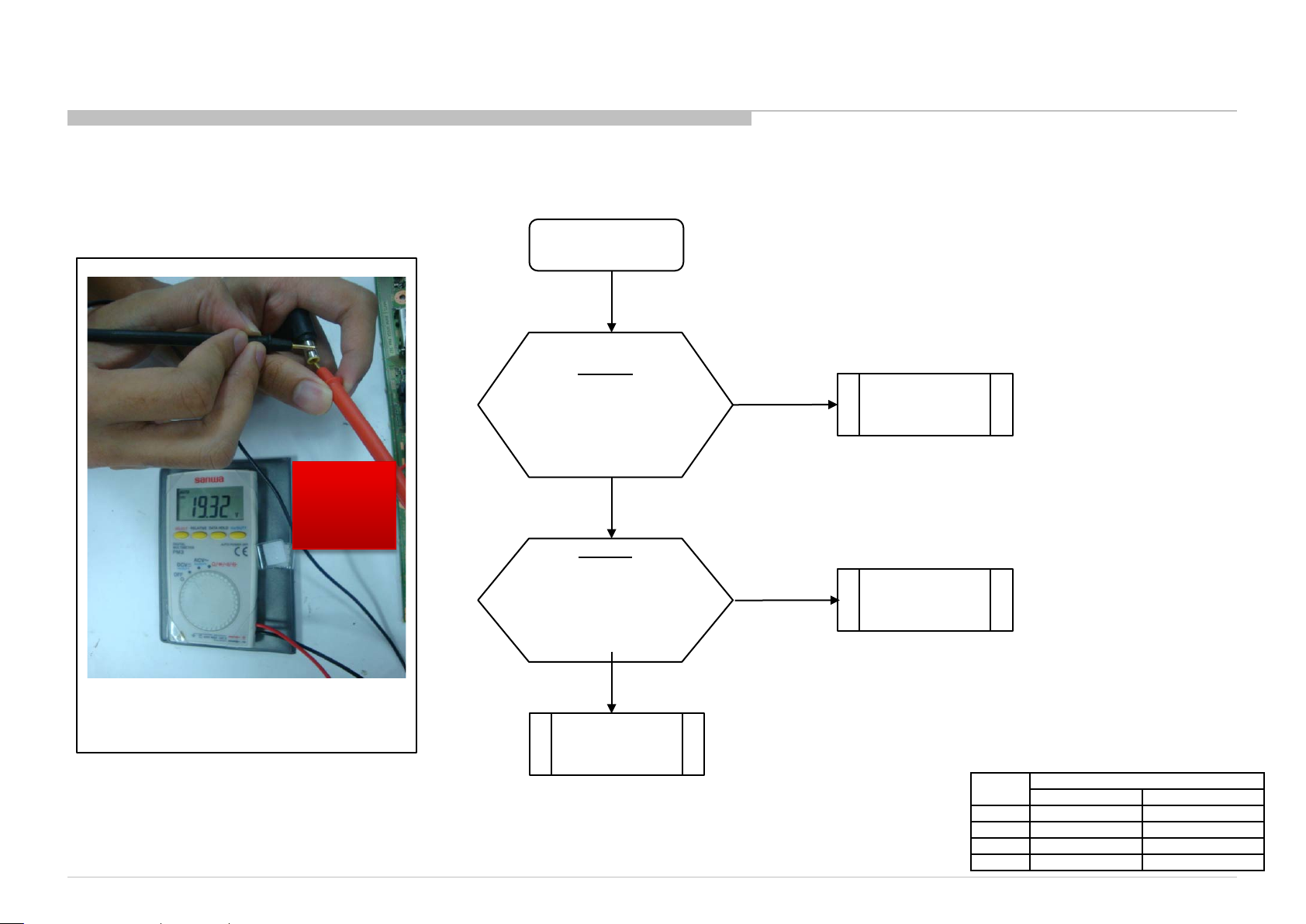
2 times Blinking
-ve
+ve
Ensure that
+ve probe is
touching the
needle.
Figure 1: How to check adaptor’s output
voltage.
B-Board
Check DC voltage at
JL6001
19V - 19.5V?
No
Adaptor
Take out adaptor
and check the output voltage.
19V – 19.5V?
(Refer Figure 2)
No
Change adaptor
Yes
Yes
Change B-board
Change B-board
B*Board Type:
Size
PAN ASIA, CHINA EUROPE, AMERICA
28” BIS 32” BIS BIL
40” BIS BIL
48” BIS BIL
B* Board Type
13
Page 14
3-3. Standby LED Blinking
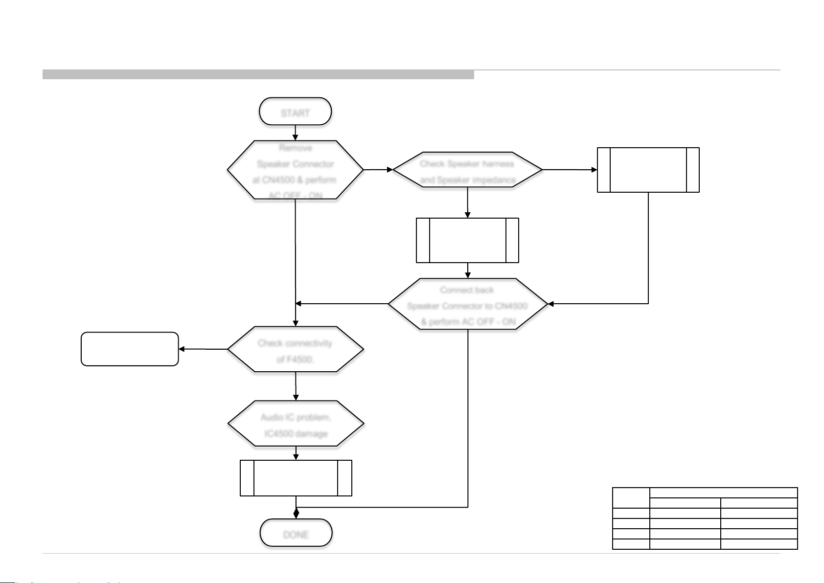
3-3-2. 3 times blinking
ITC3 CHASSIS
R410/412/413/420/422/423/424/425/426/427/428/430/433/435/
450/453/455/470/472/473/475/477/478/480/483/485/M5/M10B
START
F4500 broken
3x blinking
3x blinking
No connectivity
of F4000
3x blinking
& F4000 OK
Remove
Speaker Connector
at CN4500 & perform
AC OFF - ON
3x blinking
Check conne ctivity
of F4500.
Audio IC problem,
IC4500 damage
No 3x blinking
Check Speake r harness
and Speaker impedance
No connectivity
for speaker harness
Change
Speaker
Harness
Connect back
Speaker Conne ctor to CN4500
& perform AC OFF - ON
No 3x blinking
Speaker impedance
≠ 6~8 Ω
Change
Speaker
Change B board
DONE
B*Board Type:
Size
PAN ASIA, CHINA EUROPE, AMERICA
28” BIS 32” BIS BIL
40” BIS BIL
48” BIS BIL
B* Board Type
14
Page 15
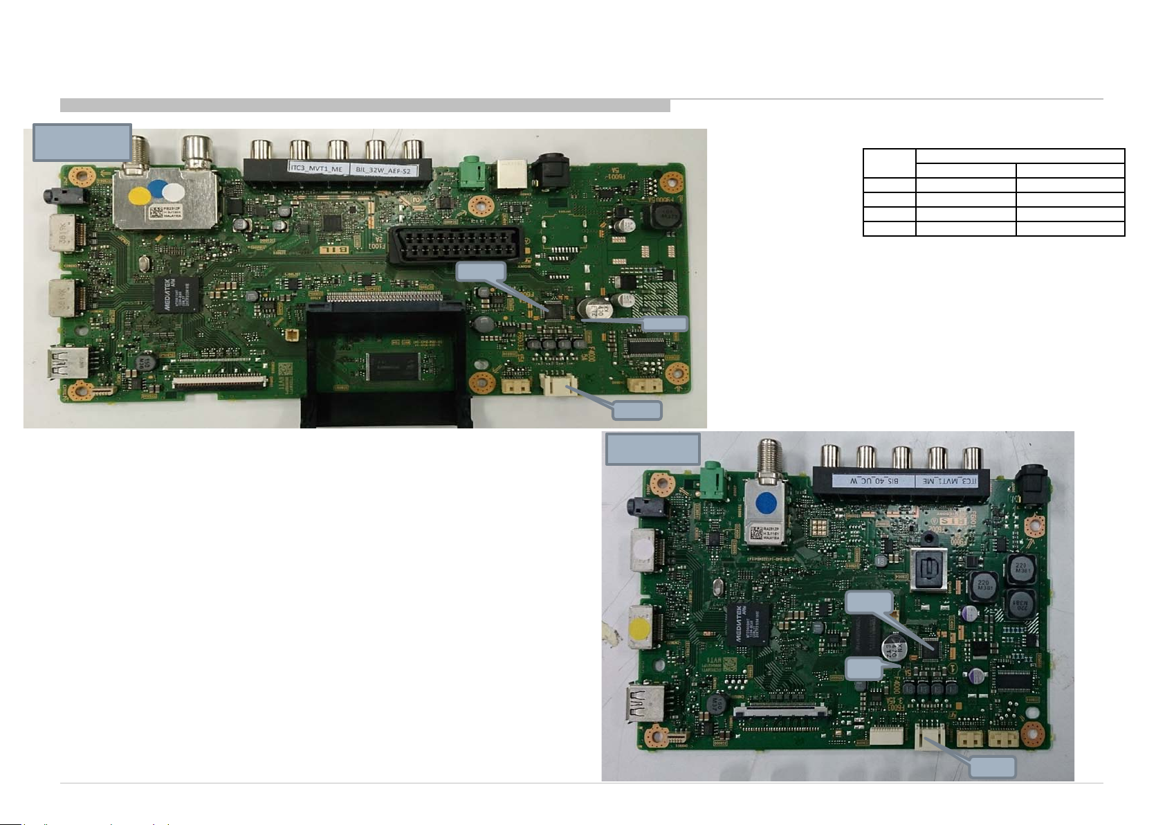
BIL_Board
IC4500
CN4500
F4500
ITC3 CHASSIS
R410/412/413/420/422/423/424/425/426/427/428/430/433/435/
450/453/455/470/472/473/475/477/478/480/483/485/M5/M10B
B*Board Type:
Size
PAN ASIA, CHINA EUROPE, AMERICA
28” BIS 32” BIS BIL
40” BIS BIL
48” BIS BIL
B* Board Type
BIS_Board
IC4500
F4500
CN4500
15
Page 16
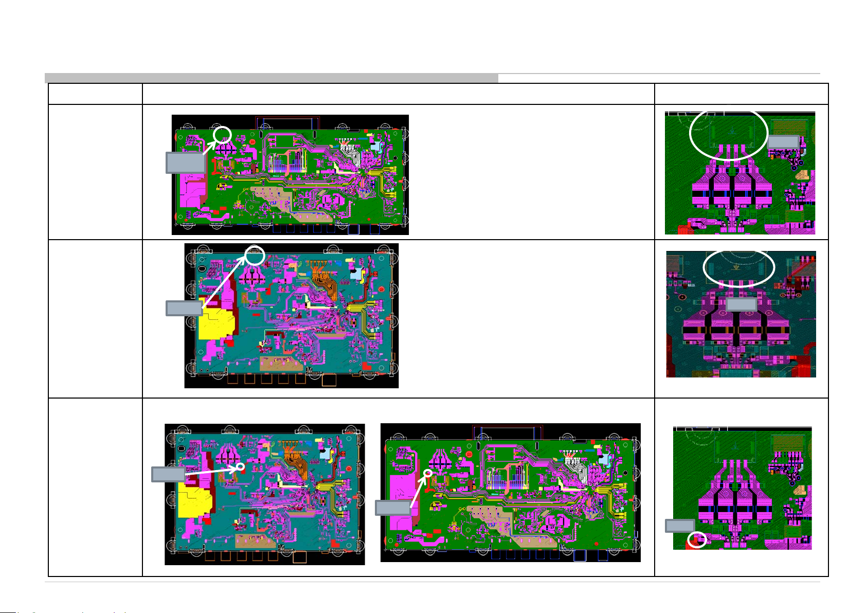
R410/412/413/420/422/423/424/425/426/427/428/430/433/435/
450/453/455/470/472/473/475/477/478/480/483/485/M5/M10B
Board Name Board PWB (A side) Detail
BIL
CN4500
CN4500
BIS
CN4500
CN4500
CN450
ITC3 CHASSIS
CN450
0
0
F4500
BIS BIL
F450
0
F4500
BIL
F450
0
16
Page 17
3-3. Standby LED Blinking
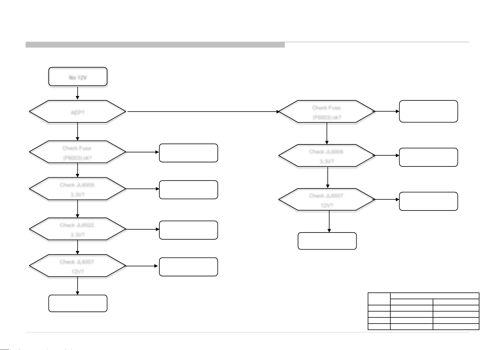
3-3-3. 4 times blinking
No 12V
ITC3 CHASSIS
R410/412/413/420/422/423/424/425/426/427/428/430/433/435/
450/453/455/470/472/473/475/477/478/480/483/485/M5/M10B
AEP?
Yes
Check Fuse .
(F6003) ok?
Ok
Check JL6009.
3.3V?
Yes
Check JL6022.
3.3V?
Yes
Check JL6007.
12V?
No
No
No
No
No
Fuse
B-Board
B-board
DDCON
(IC6010)
Check Fuse.
(F6003) ok?
Yes
Check JL6009.
3.3V?
Yes
Check JL6007.
12V?
Yes
LVDS
No
Fuse
No
B-board
No
DDCON
Yes
LVDS
B*Board Type:
Size
PAN ASIA, CHINA EUROPE, AMERICA
28” BIS 32” BIS BIL
40” BIS BIL
48” BIS BIL
B* Board Type
17
Page 18

BIL
LVDS FFC
CONNECTOR
JL600
ITC3 CHASSIS
R410/412/413/420/422/423/424/425/426/427/428/430/433/435/
450/453/455/470/472/473/475/477/478/480/483/485/M5/M10B
B*Board Type:
Size
PAN ASIA, CHINA EUROPE, AMERICA
28” BIS 32” BIS BIL
40” BIS BIL
48” BIS BIL
F600
3
9
JL600
7
B* Board Type
BIS
LVDS FFC
CONNECTO
R
JL60
F600
JL60
12
3
09
18
Page 19
3-3. Standby LED Blinking
3-3-4. 5 times blinking
START
ITC3 CHASSIS
R410/412/413/420/422/423/424/425/426/427/428/430/433/435/
450/453/455/470/472/473/475/477/478/480/483/485/M5/M10B
Remove and reinsert LVDS Flat
Flexible Cable (FFC) at B-Board and
Panel Side
5x Blinkin g is Still
Observed
Replace LVDS Flat Flexible
Cable (FFC)
5x Blinkin g is Still
Observed
TV Boots Up
Normally
TV Boots Up
Normally
Incorrect FFC
Insertion
LVDS
Cable Issue
Replace B-Board
5x Blinking is Still
Observed
Replace
*O-Cell or *Panel Module
END
TV Boots Up
Normally
TV Boots Up
Normally
* O-Cell or Panel
Module replacement
depends on se rvice
capabilities
B*Board Type:
Size
PAN ASIA, CHINA EUROPE, AMERICA
28” BIS 32” BIS BIL
40” BIS BIL
48” BIS BIL
B-Board Issue
O-Cell Issue
B* Board Type
19
Page 20
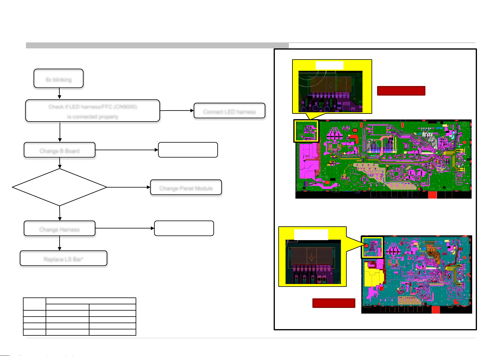
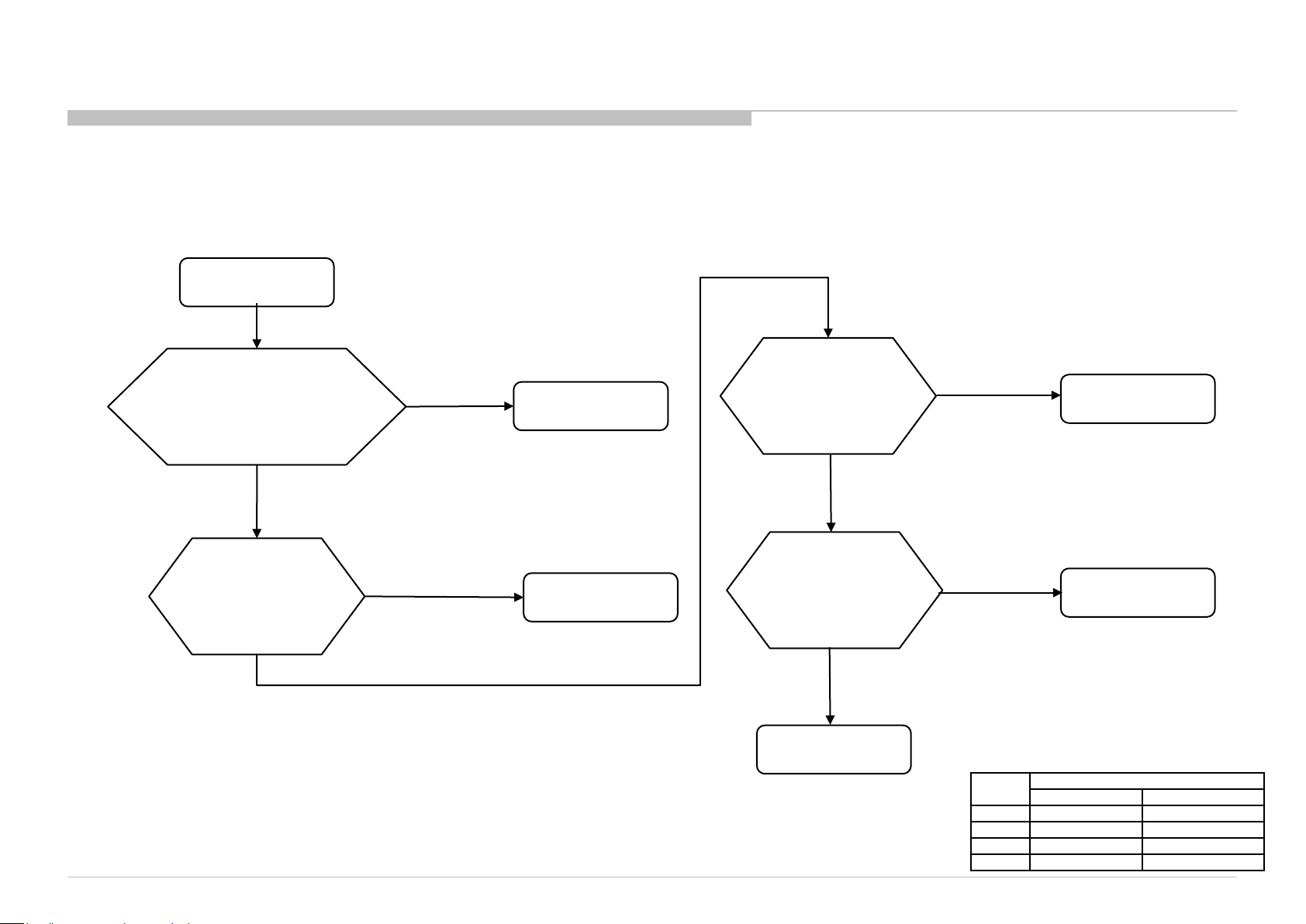
3-3. Standby LED Blinking
3-3-5. 6 times blinking
6x blinking
ITC3 CHASSIS
R410/412/413/420/422/423/424/425/426/427/428/430/433/435/
450/453/455/470/472/473/475/477/478/480/483/485/M5/M10B
Location of CN9000
CN900
0
CN9000
Check if LED harness/FFC (CN9000)
is connected properly
Symptom gone
Change B Board
6x blinking
Able to repair
Panel Module
No
Change Panel Module
Yes
Symptom gone
Change Harness Harness
6x blinking
*To avoid changing all LS bar, please follow steps below
Replace LS Bar*
B*Board Type:
Size
PAN ASIA, CHINA EUROPE, AMERICA
28” BIS 32” BIS BIL
40” BIS BIL
48” BIS BIL
B* Board Type
(1) Turn off AC
(2) Unplug DC adaptor from DC jack
(3) Plug in DC adaptor to DC jack
(4) Turn on AC
(5) LS bar will turn on for ~4s before 6x blinking
(6) Observe which LS bar cannot turn on during power on
(7) Replace LS bar that failed to turn on
NG
Connect LED harness
B board
BIL Board
CN9000
CN9000
BIS Board
20
Page 21
3-4. No Picture
3-4-1. General
No Picture
ITC3 CHASSIS
R410/412/413/420/422/423/424/425/426/427/428/430/433/435/
450/453/455/470/472/473/475/477/478/480/483/485/M5/M10B
Check Input Source:
-Tuner
- MHL/HDMI
-Video/Component
Input NG
Replace Input
Source
Input
OK
Replace B-Board
Replace LVDS FFC
Harness
Picture OK
LVDS FFC
Harness
Problem
Still No
Picture
Still No
Picture
PANEL_VCC_SW at
JL6007 on
(12V±0.8V)
or +12V DDCON
*Panel Module
or *O-Cell
Problem
Check
B-Board
Adaptor
Problem
+12V NG
+12V
OK
CHECK BL_ON on
B-Board at JL9012.
HIGH (+3 .3V): OK
LOW (0V): NG
BL_ON NG
Backlight or LED Driver
Problem
END
BL_ON
OK
Picture OK
B-Board Issue
Picture OK
Panel or O-Cell
Issue
* O-Cell or Panel
Module replacement
depends on se rvice
capabilities
B*Board Type:
Size
PAN ASIA, CHINA EUROPE, AMERICA
28” BIS 32” BIS BIL
40” BIS BIL
48” BIS BIL
B* Board Type
21
Page 22
“NO PICTURE” Probing Points
ITC3 CHASSIS
R410/412/413/420/422/423/424/425/426/427/428/430/433/435/
450/453/455/470/472/473/475/477/478/480/483/485/M5/M10B
BL_ON
JL9012
Note :
BL_ON = +3.3V (OK)
BL_ON = 0V (NG)
JL9012
PANEL_VCC
JL6007
Note :
PANEL_VCC_S W = 12V±0.8V
BIL Board
PANEL_VCC BL_ON
JL6007
Note :
BL_ON = +3.3V (OK)
BL_ON = 0V (NG)
BIS Board
Note :
PANEL_VCC_SW = 12V±0.8V
B*Board Type:
Size
PAN ASIA, CHINA EUROPE, AMERICA
28” BIS 32” BIS BIL
40” BIS BIL
48” BIS BIL
B* Board Type
22
Page 23
3-5. Audio
3-5-1. General
ITC3 CHASSIS
R410/412/413/420/422/423/424/425/426/427/428/430/433/435/
450/453/455/470/472/473/475/477/478/480/483/485/M5/M10B
Audio Problem
Main Speaker No Sound
HP Out No Sound
Video/Component or HDMI 2
no sound?
Analog RF no sound?
HDMI Audio no sound?
Refer “Main Speaker No
Sound”
Refer “HP Out
No Sound”
Refer “Analog Audio Input
No Sound”
Refer “Analog RF
No Sound”
Refer “HDMI Audio
No Sound”
USB Audio no sound?
Refer “USB Audio
No Sound”
23
Page 24
3-5. Audio
3-5-2. Main Speaker No Sound
ITC3 CHASSIS
R410/412/413/420/422/423/424/425/426/427/428/430/433/435/
450/453/455/470/472/473/475/477/478/480/483/485/M5/M10B
Sound
Sound
Change Speaker Harness
No Sound
Change Speaker
No Sound
F4500 broken
Sound
No connectivity for speaker
harness
Speaker Impedance
≠ 6~8 Ω
No connectivity
of F4000
START
Do a Factory Setting
No Sound
Check Speaker Harness
connectivity
No Sound
Check Speaker Impedance
No Sound
Check fuse connectivity
at F4000
Main Speaker No Sound
F4000 OK
Audio IC problem
IC4000 damage
Change B-Board
DONE
No Sound
B*Board Type:
Size
PAN ASIA, CHINA EUROPE, AMERICA
28” BIS 32” BIS BIL
40” BIS BIL
48” BIS BIL
B* Board Type
24
Page 25

ITC3 CHASSIS
R410/412/413/420/422/423/424/425/426/427/428/430/433/435/
450/453/455/470/472/473/475/477/478/480/483/485/M5/M10B
B*Board Type:
BIL_Board
IC450
Size
PAN ASIA, CHINA EUROPE, AMERICA
B* Board Type
28” BIS 32” BIS BIL
40” BIS BIL
48” BIS BIL
0
F4500
CN45
00
BIS_Board
IC4500
F4500
CN4500
25
Page 26

3-5. Audio
3-5-3. Headphone (HP) Out No Sound
ITC3 CHASSIS
R410/412/413/420/422/423/424/425/426/427/428/430/433/435/
450/453/455/470/472/473/475/477/478/480/483/485/M5/M10B
Headphone
problem
Sound
Sound
START
Do a Factory Setting
No Sound
Use another Headphone
No Sound
HP IC (IC4000) or Main IC (IC5000) problem
Change B-board
Headphone (HP) No Sound
& Headphone OK
DONE
B*Board Type:
Size
PAN ASIA, CHINA EUROPE, AMERICA
28” BIS 32” BIS BIL
40” BIS BIL
48” BIS BIL
B* Board Type
26
Page 27

BIL_Board
IC5000
IC400
ITC3 CHASSIS
R410/412/413/420/422/423/424/425/426/427/428/430/433/435/
450/453/455/470/472/473/475/477/478/480/483/485/M5/M10B
B*Board Type:
Size
PAN ASIA, CHINA EUROPE, AMERICA
28” BIS -
0
32” BIS BIL
40” BIS BIL
48” BIS BIL
B* Board Type
BIS_Board
IC4000
IC5000
27
Page 28

3-5. Audio
3-5-4. HDMI Audio No Sound
Sound
ITC3 CHASSIS
R410/412/413/420/422/423/424/425/426/427/428/430/433/435/
450/453/455/470/472/473/475/477/478/480/483/485/M5/M10B
START
Sound
Do a Factory Setting
NG
Sound
Sound
Change HDMI
cable
Change HDMI source
Change to supported
format
HDMI cable,
ok?
No Sound
NG
HDMI source,
ok?
No Sound
NG
*HDMI sound
format ok?
No Sound
Main IC (IC5000) or Audio IC (IC4500) problem
Change B-board
DONE
& HDMI cable OK
& HDMI source OK
& HDMI format OK
* Please refer to IM for supported HDMI
audio format.
B*Board Type:
Size
PAN ASIA, CHINA EUROPE, AMERICA
28” BIS 32” BIS BIL
40” BIS BIL
48” BIS BIL
B* Board Type
28
Page 29

3-5. Audio
3-5-5. Analog RF No Sound
ITC3 CHASSIS
R410/412/413/420/422/423/424/425/426/427/428/430/433/435/
450/453/455/470/472/473/475/477/478/480/483/485/M5/M10B
Analog RF input no
sound
Change RF cable
Change RF
source/channel
Refer “Speaker No
Sound”
Refer “Tuner
Problem”
NG
NG
NG
NG
RF cable,
ok?
OK
RF source,
ok?
OK
Raster sound,
ok?
OK
Tuning,
ok?
OK
UI setting , ok?
(TV System, AFT, Audio Filter)
OK
Change B-board
NG
Correct UI
B*Board Type:
Size
PAN ASIA, CHINA EUROPE, AMERICA
28” BIS 32” BIS BIL
40” BIS BIL
48” BIS BIL
B* Board Type
29
Page 30

3-5. Audio
3-5-6. USB No Sound
ITC3 CHASSIS
R410/412/413/420/422/423/424/425/426/427/428/430/433/435/
450/453/455/470/472/473/475/477/478/480/483/485/M5/M10B
START
Sound
Do a Factory Setting
Sound
Change to supported
format
Sound
Change USB
thumbdrive
No Sound
NG
*Confirm USB audio
format
No Sound
NG
Check USB thumbdrive
Condition
No Sound
Main IC (IC5000) or Audio IC (IC4500) problem
Change B-board
DONE
& USB format OK
& USB condition OK
*Confirm with OSD on bottom panel,
if playback not support.
*Please refer to IM for detail supported USB
audio format.
B*Board Type:
Size
PAN ASIA, CHINA EUROPE, AMERICA
28” BIS 32” BIS BIL
40” BIS BIL
48” BIS BIL
B* Board Type
30
Page 31

3-6. Video Problem
3-6-1. General
Picture On Screen
Distorted Or Missing
Backlight turns
ON?
Yes
Tuner, OK?
Yes
Video , OK?
No
No
No
Check LED 6x
times blink?
No
Refer “Tuner
Problem”
Refer “Video
Problem”
Yes
R410/412/413/420/422/423/424/425/426/427/428/430/433/435/
450/453/455/470/472/473/475/477/478/480/483/485/M5/M10B
Refer to Power Troubleshoot (STANDBY LED BLINK 6x
times blinking
Yes
Check Eco Power
Saving ON?
Refer to IM Eco
Power Saving
Setting
No
ITC3 CHASSIS
Yes
Component, OK?
Yes
HDMI, OK?
Yes
MHL, OK?
Yes
Finish
No
No
No
Refer “Component
Problem”
Refer “HDMI/MHL
Problem”
Refer “HDMI/MHL
Problem”
Change B- board
B*Board Type:
Size
PAN ASIA, CHINA EUROPE, AMERICA
28” BIS 32” BIS BIL
40” BIS BIL
48” BIS BIL
B* Board Type
31
Page 32

3-6. Video Problem
3-6-2. BIL Component, Video & HDMI Block
5V
Input detecti on
Share Video/ Component
ITC3 CHASSIS
R410/412/413/420/422/423/424/425/426/427/428/430/433/435/
450/453/455/470/472/473/475/477/478/480/483/485/M5/M10B
75ohm
IC5000
HDMI1 HDMI2/MHL
32
Page 33

3-6. Video Problem
BIL Video/Component Sch ematic Diagram
ITC3 CHASSIS
R410/412/413/420/422/423/424/425/426/427/428/430/433/435/
450/453/455/470/472/473/475/477/478/480/483/485/M5/M10B
PG3 PG6
33
Page 34

3-6. Video Problem
3-6-3. BIL Video (No Picture)
ITC3 CHASSIS
R410/412/413/420/422/423/424/425/426/427/428/430/433/435/
450/453/455/470/472/473/475/477/478/480/483/485/M5/M10B
No Picture
Video NG
No Picture
Check signal source
or cable.
OK
Check Input jack
‘J3000’ connection
OK
Check input signal
1.0Vp-p at R3029
OK
Confir m w ave f orm at
C3020 (face to IC5000)
same as R ef 5
(CB input patter n)
OK
IC5000 defect
Video Signal
NG
Source problem
or cable problem
Make sure jack
NG
proper connection
to board
NG
R3029
connection/defect
NG
Confirm R3029 &
C3020 conne ction
and value
Ref5
Component
No Picture
Video Signal
Check signal source
or cable.
OK
Check Input jack
‘J3000’ connection
Check input
signal 1.0Vp-p
at R3029_Y0P line ,
R3031_PB0P line &
R3032_PR0P line
Confirm waveform at
OK
OK
C3020 (face to IC5000)
same as Ref6.
Ref6
Ref7
Confirm waveform at
C3022 (face to IC5000)
same as Ref7.
Confirm waveform at
C3023 (face to IC5000)
same as Ref8.
Input CB pattern.
Ref8
OK
NG
Source problem
or cable problem
NG
Make sure jack
proper connection
to board
NG
R3029, R3031,
R3032
connection/defect
Confirm R3010, C3009,
R3029, C3020 (Y0P line)
NG
Confirm R3011, C3010,
R3031, C3022 (PB0P line)
Confirm R3012, C3011,
R3032, C3023 (PR0P line)
connection and value
connection and value
connection and value
IC5000 defect
34
Page 35

3-6. Video Problem
3-6-4. BIL Video (Scart)
ITC3 CHASSIS
R410/412/413/420/422/423/424/425/426/427/428/430/433/435/
450/453/455/470/472/473/475/477/478/480/483/485/M5/M10B
BIL Video
SCART CVBS
No Picture
Check
RGB_SWITCH
IC5000 U12
[SOY1] at R3015
OK [LOW] OK [LOW]
Check input signal
1.0Vp-p at R3029
OK
Confir m w ave f orm
at C3028 (face IC5000)
same as R ef 9
(SCART CVBS
input pattern)
OK
IC5000 defect
NG
[HIGH]
NG
NG
Check CN3000
Connection
R3029
connection/defect
Detai le d ch eck
CN3000 Pin
No.20 signal path
Ref9
Ref10
Ref11
Ref12
SCART RGB
No Picture
Check
RGB_SWITCH
IC5000 U12
[SOY1] at R3015
Check input signal
0.7Vp-p
at R3029_Y0P line ,
R3031_PB0P line &
R3032_PR0P line
OK
Confir m w ave f orm at
C3024 (f ac e t o IC 5000)
same as R ef 10.
Conf ir m wav ef or m at
C3026 (f ac e t o IC 5000)
same as R ef 11.
Confir m w ave f orm at
C3027 ( fac e t o IC 5000)
same as Ref12.
Input CB pattern.
OK
NG
[HIGH]
NG
Check CN3000
Connection
R3029, R3031,
R3032
connection/defect
NG
R3022, C3016 (PR1P line)
Confirm C3024 (Y1P line)
con n ection . Detai le d
Check CN3000 Pin N o.7
Confirm R3025, C3026,
R3021 (PB1P line)
connection and value.
Detailed Check CN3000
Pin No.11 signal path.
Confirm R3026, C3027,
connection and value.
Detailed Check CN3000
Pin No.15 signal path.
signal path.
IC5000 defect
35
Page 36

ITC3 CHASSIS
R410/412/413/420/422/423/424/425/426/427/428/430/433/435/
450/453/455/470/472/473/475/477/478/480/483/485/M5/M10B
3-6. Video Problem
BIL FOR VIDEO NG (NO PICTURE)
J3000
R302
9
C302
B*Board Type:
Size
PAN ASIA, CHINA EUROPE, AMERICA
28” BIS 32” BIS BIL
40” BIS BIL
48” BIS BIL
0
B* Board Type
BIS FOR VIDEO NG (NO PICTURE)
J3000
C3
01
6
R3
02
9
36
Page 37

ITC3 CHASSIS
R410/412/413/420/422/423/424/425/426/427/428/430/433/435/
450/453/455/470/472/473/475/477/478/480/483/485/M5/M10B
3-6. Video Problem
BIL FOR COMPONENT NG (NO PICTURE)
C301
1
R301
R301
2
1
C301
C300
9
0
R301
0
J3000
R302
C302
9
B*Board Type:
Size
PAN ASIA, CHINA EUROPE, AMERICA
28” BIS 32” BIS BIL
40” BIS BIL
48” BIS BIL
C302
0
R303
1
C302
3
2
R303
2
B* Board Type
BIS FOR COMPONENT NG (NO PICTURE)
C30
C30
C30
16
18
17
R30
29
R30
15
C30
11
R30
R30
13
14
C30
12
C30
10
32
31
R30
R30
37
Page 38

3-7. HDMI
3-7-1. General
ITC3 CHASSIS
R410/412/413/420/422/423/424/425/426/427/428/430/433/435/
450/453/455/470/472/473/475/477/478/480/483/485/M5/M10B
HDMI Problem
Check HDMI input source signal or
cable.
OK
Confirm HDMI input source format /
resolution supported by TV?
OK
Check HDM I jack.
OK
Change board circuit
NG
HDMI Signal Source Problem or cable
problem
NG
Change HDMI input source to TV supported
format
NG
Change B-board
B*Board Type:
Size
PAN ASIA, CHINA EUROPE, AMERICA
28” BIS 32” BIS BIL
40” BIS BIL
48” BIS BIL
B* Board Type
38
Page 39

3-8. MHL
3-8-1. No Picture
Change phone or
source
Change MHL
cable
NO
NO
ITC3 CHASSIS
R410/412/413/420/422/423/424/425/426/427/428/430/433/435/
450/453/455/470/472/473/475/477/478/480/483/485/M5/M10B
No picture
Phone or source supported MH L
(phone spec and OS support etc)
YES
Use supported MHL cable
Change B-board
YES
39
Page 40

3-8. MHL
3-8-2. MHL No Charging
ITC3 CHASSIS
R410/412/413/420/422/423/424/425/426/427/428/430/433/435/
450/453/455/470/472/473/475/477/478/480/483/485/M5/M10B
No charging
Change MHL
cable
IC3603 NG
YES
YES
Check VBUS voltage at IC3603 PIN
6 = 5Vdc
NO
Check IC3603 pin3 voltage =
3.3Vdc
NO
Change B-board
B*Board Type:
Size
PAN ASIA, CHINA EUROPE, AMERICA
28” BIS 32” BIS BIL
40” BIS BIL
48” BIS BIL
B* Board Type
40
Page 41

ITC3 CHASSIS
R410/412/413/420/422/423/424/425/426/427/428/430/433/435/
450/453/455/470/472/473/475/477/478/480/483/485/M5/M10B
3-8. MHL
BIL BOARD
CL3605
B*Board Type:
B* Board Type
IC3603
IC3603
Size
PAN ASIA, CHINA EUROPE, AMERICA
28” BIS 32” BIS BIL
40” BIS BIL
48” BIS BIL
BIS BOARD
Pin1
Pin6
CL360
IC360
3
IC360
5
Pin6
3
P
in
1
41
Page 42

3-9. Tuner
3-9-1. General
ITC3 CHASSIS
R410/412/413/420/422/423/424/425/426/427/428/430/433/435/
450/453/455/470/472/473/475/477/478/480/483/485/M5/M10B
RF input no picture / noisy picture
Check RF source cable and
antenna, OK?
OK
Check JL1001 = +3.3V?
OK
Tuning for Digital or
Analog?
Analog
Refer Analog Tuning
NG
NG
Digital
Change RF cable and antenna
Change B Board
Refer Digital Tuning
B*Board Type:
Size
PAN ASIA, CHINA EUROPE, AMERICA
28” BIS 32” BIS BIL
40” BIS BIL
48” BIS BIL
B* Board Type
42
Page 43

BIL BOARD
ITC3 CHASSIS
R410/412/413/420/422/423/424/425/426/427/428/430/433/435/
450/453/455/470/472/473/475/477/478/480/483/485/M5/M10B
JL1001
JL1001
BIS BOARD
43
Page 44

3-9. Tuner
3-9-1. Analog Tuning
FOR AN AL OG T UN IN G: @ All de st inatio n.
Analog Tuning
For LA-ISDB(BR/AR) and LA-T2(COL) only
ITC3 CHASSIS
R410/412/413/420/422/423/424/425/426/427/428/430/433/435/
450/453/455/470/472/473/475/477/478/480/483/485/M5/M10B
Fig.1
Destination
RF level
(dBm)
RF level
(dBuV)
IFAGC1 (V)
For Other destination
Channel can be lock?
OK
Picture quality become noisy
OK
Confirm RF leve l and IFAGC1 (V)
of Analog RF (Fig: 1)
NG
Confirm ANT or Cable connection
NG
Check below part mounting
condition, OK?
FB1002, FB1003, C1002, C1003,
R1011, R1012, R1015, C1012,
R1001, R1003, C1016, R1013
OK
NG
BR/LA-T2 -35 80 0.514
B*Board Type:
Size
PAN ASIA, CHINA EUROPE, AMERICA
28” BIS 32” BIS BIL
40” BIS BIL
48” BIS BIL
IFAGC1 (V) tolerance ±0.1V
NG
B* Board Type
OK
Please re-upgrade Firmware (PKG),
Check again Picture quality?
OK
Done (End)
NG
Change B-board
44
Page 45

BIL BOARD
ITC3 CHASSIS
R410/412/413/420/422/423/424/425/426/427/428/430/433/435/
450/453/455/470/472/473/475/477/478/480/483/485/M5/M10B
R1015
R1012
R1011
R1003
C1012
R1001
FB100
3
FB100
2
C1002
C1003
R1013 C1016
B*Board Type:
Size
PAN ASIA, CHINA EUROPE, AMERICA
28” BIS 32” BIS BIL
40” BIS BIL
48” BIS BIL
B* Board Type
45
Page 46

BIS BOARD
ITC3 CHASSIS
R410/412/413/420/422/423/424/425/426/427/428/430/433/435/
450/453/455/470/472/473/475/477/478/480/483/485/M5/M10B
R1015
R1012
R1011
R1001 C1012
R1003
C1003
C1002
FB100
FB100
R1013 C1016
3
B*Board Type:
2
Size
PAN ASIA, CHINA EUROPE, AMERICA
28” BIS 32” BIS BIL
40” BIS BIL
48” BIS BIL
B* Board Type
46
Page 47

3-9. Tuner
3-9-2. Digital Tu ning
ITC3 CHASSIS
R410/412/413/420/422/423/424/425/426/427/428/430/433/435/
450/453/455/470/472/473/475/477/478/480/483/485/M5/M10B
FOR DIGITA L TUN ING: @ AEP-T2,AEP-T2S2,PAD2,CH,LA-ISDB(BR/AR) and LA-T2(COL).
Digital Tuning
For LA-ISDB(BR/AR) and LA-T2(COL) only For AEP-T2S2 only
Confirm ANT or Cable connection
Notes:
- Voltage for DEMOD_VIN = 1.2V for CH, 1.1V for other destinat ion.
- Parts for AGC_S: C1094,R1160(for BIL).
- Parts for AGC2: R1016,C1022,R1003,R1001,C1012.
- Parts for DEM_RESET: C1034,C1038,R1049,R1036,C1030,R1057.
- Parts for TU_DAT A_DEMOD: R1004,R1024.
- Parts for O SC_ ENBN -1: C1071,R1050 ( for BIL).
- Parts for IF2_P_DEMOD: 1070,FB1003,C1001,R1010,C1009,R1 018.
- Parts for IF2_N_DEMOD: 1069,FB1002,C1000,R1009,C 1008,R1017 .
- Parts for TU_CLK_DEMOD: R1005,R1025.
-Parts for TS line: R1028,R1030,R1032,R1038,C1072,RB1004 (for BIL) /
R1028,R1030,R1032,R1038,C1071 (for BIS).
-Parts for Tuner Control:
R1007,R1006,C1004,C1005,C1043,C1044,R5015,R5016,
RB5004(BIS)/RB5005(BIL).
Check M’t condition
RF level =
in AGC2/IF2_N_DEMOD/
IF2_P_DEMOD line
OK
Please re-upgrade Firmware
(PKG),
Check again Picture quality?
OK
Done (End)
Confirm ANT or Sate llite connection
For Other destination
Sound is normal?
No sound
Confirm BER of digital RF by Service mode
NG
Confirm Power supply for Digital Demod
DEMOD_VIN and 3.3V
OK
Confirm Tune r and De mod control line
M_SCL / M_SDA / DEM_RESET / OSC_ENBN-1 / TU_DATA_DEMOD
/ TU_CLK_DEMOD / AGC_S (Satellite only)
OK
High
Confirm RF Level and AGC
of Digital RF by Service mode
B*Board Type:
Size
PAN ASIA, CHINA EUROPE, AMERICA
28” BIS 32” BIS BIL
40” BIS BIL
48” BIS BIL
B* Board Type
OK
Error free
NG
NG
RF level = Low
NG
Check IC5000 (MTK)
Check IC5000 (MTK) and
mount condition in TS line
Check Power supply
Circuit for Digital Demod
Check mount condition
in Tuner and Demod control line
Change B-board
47
Page 48

BIL BOARD
RB10
04
ITC3 CHASSIS
R410/412/413/420/422/423/424/425/426/427/428/430/433/435/
450/453/455/470/472/473/475/477/478/480/483/485/M5/M10B
RB5004
R1015
R1012
R1011
R1160
C1094
C1034
R1057
C1030
R1036
C1038
R1049
R1010
C1043
C1044
R1017
R1018
C1008
C1009
R1009
C1071
R1050
R1016
C1022
R1025 R1024
RB5005
R1038
R1032
R1030
R1028
R1003
R1007
R1006
C1004
C1072
R5016
R5015
C1005
C1012
R1001
C1001
C1000
FB100
3
FB100
2
C1002
C1003
R1013
C1016
C1070
C1069
48
Page 49

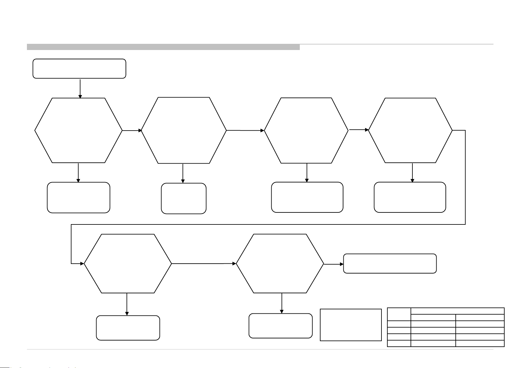
3-10. Ethernet
3-10-1. General
ITC3 CHASSIS
R410/412/413/420/422/423/424/425/426/427/428/430/433/435/
450/453/455/470/472/473/475/477/478/480/483/485/M5/M10B
Check if TV has good
cable connection
Set-up Network setup
Failed
Check if the Ethernet
cable is good
NG
Change a good cable
OK
OK
Check if any abnormal
or broken point on
Ethernet Connector
No
Check if TV has MAC Address
Set-up Network setup
No
Yes
Yes
Connector NG
Change B Board
T7000 or Main IC NG
Change B Board
Invalid MAC Address
Change B Board
B*Board Type:
Size
PAN ASIA, CHINA EUROPE, AMERICA
28” BIS 32” BIS BIL
40” BIS BIL
48” BIS BIL
B* Board Type
49
Page 50

3-11. IR
ITC3 CHASSIS
R410/412/413/420/422/423/424/425/426/427/428/430/433/435/
450/453/455/470/472/473/475/477/478/480/483/485/M5/M10B
TV cannot be controlled
by remote commander
Green LED light
at Power LED indicator
NG
Confirm Harness connection
OK on B-Board and HIL Board
NG
Change Harness
NG
Change HIL board
NG
Change B-board
OK
OK
OK
OK
Green LED blinks at Power indicator
when using commander
near sensor’s window
NG
Harness loose connection
Harness NG
HIL board NG
OK
Mechanical
(ex. Bezel, Guidelight)
B*Board Type:
Size
PAN ASIA, CHINA EUROPE, AMERICA
28” BIS 32” BIS BIL
40” BIS BIL
48” BIS BIL
B* Board Type
50
Page 51

3-12. Switch Unit Buttons
Switch Unit NOT FUNCTIONING
ITC3 CHASSIS
R410/412/413/420/422/423/424/425/426/427/428/430/433/435/
450/453/455/470/472/473/475/477/478/480/483/485/M5/M10B
*VOLTAGE LEVEL FOR EACH PRESSED BUTTON
Check Wire Harness
And Connector
Connectivity?
OK
Check 3.3V
in Pin2, CN1
(Switch Unit)
OK
*Check
Pin 1 Voltage Level
in CN1
OK
Change B-board
NG
NG
NG
NG
Change Wire Harness
And connect properly
Check 3.3V in Pin 7,
CN9900 on
B-board
OK
Change Switch Unit
KEY Voltage
(average)
-
+
CH/Input
No Input
0.000
1.114
1.693
2.420
Voltage range
0.00000 – 0.82353
0.83451 – 1.37255
1.383529 – 2.03137
2.04235 – 2.80000
B*Board Type:
Size
PAN ASIA, CHINA EUROPE, AMERICA
28” BIS 32” BIS BIL
40” BIS BIL
48” BIS BIL
B* Board Type
51
Page 52

ITC3 CHASSIS
R410/412/413/420/422/423/424/425/426/427/428/430/433/435/
450/453/455/470/472/473/475/477/478/480/483/485/M5/M10B
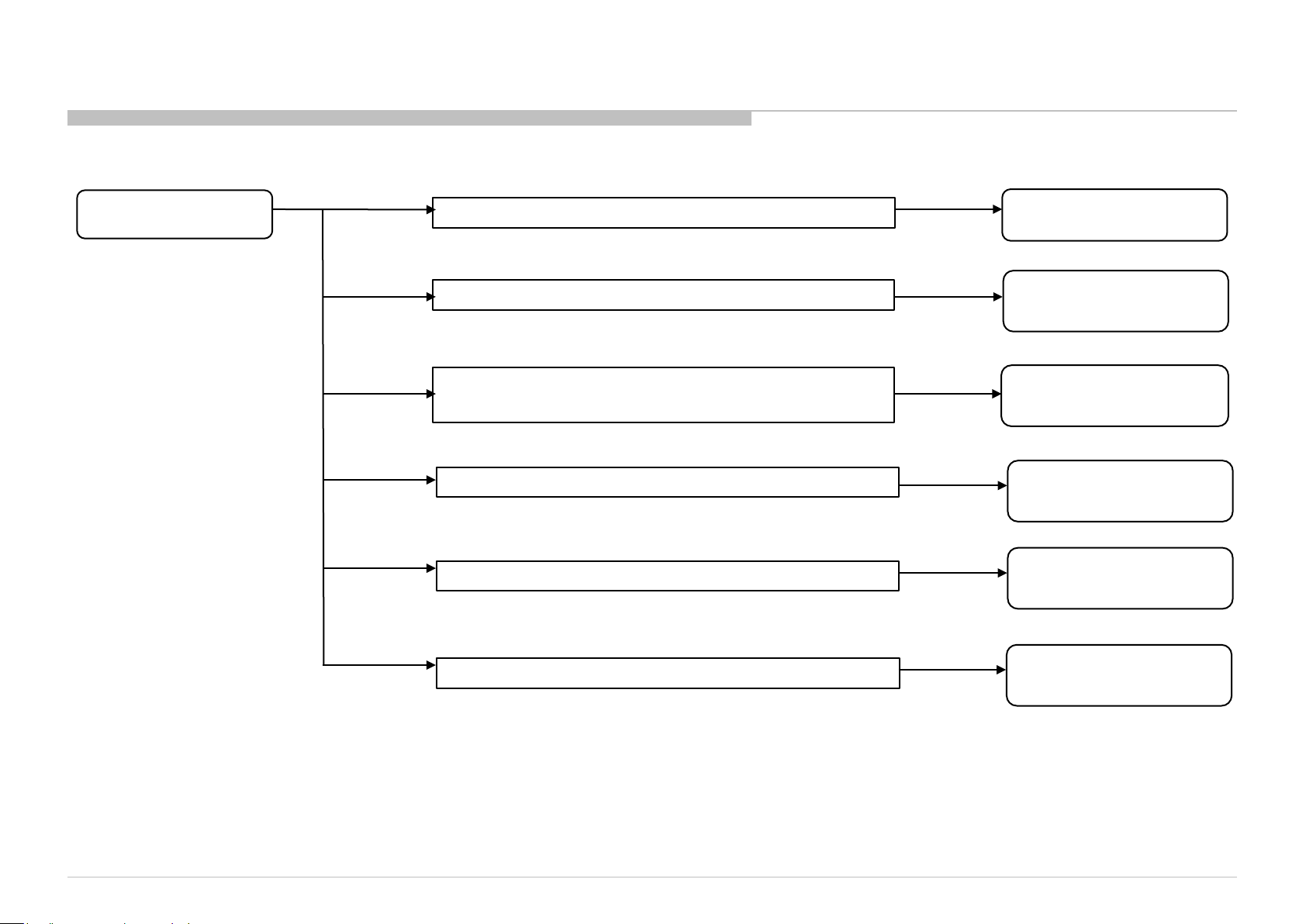
3-13. Wifi
3-13-1. Wifi Module
START
Does WiFi function
turned on at TV?
Open Detail
- Turn On WiFi
3-13. Wifi
3-13-2. Turn On Wifi
Turn On WiFi
TV UI:
HOME -> SETTINGS ->
SYSTEM SETTING ->
SETUP -> Wi-Fi SETUP ->
Wi-Fi DIRECT
NG
OK
WiFi Direct Setting
Device Can
Be Connecte d?
END
Open Detail
- Hardware Defect
Open Detail
-Hardware Defect
52
Page 53

3-13. Wifi
3-13-3-Hardware Defect
Hardware Defect
ITC3 CHASSIS
R410/412/413/420/422/423/424/425/426/427/428/430/433/435/
450/453/455/470/472/473/475/477/478/480/483/485/M5/M10B
Check harness
connection insertion
is OK
between WiFi
and Bxx
OK
Change harness
between B- board
and WiFi
NG
OK
NG
Main Harness
Connect properly
NG
Check Input Power,
is it 5V?
TP: VCC
YES
OK
Loose harness
NO
Change Bxx
board
Change
Wi-Fi module
OK
Wi-Fi module
53
Page 54

3-13. Wifi
Input Power
ITC3 CHASSIS
R410/412/413/420/422/423/424/425/426/427/428/430/433/435/
450/453/455/470/472/473/475/477/478/480/483/485/M5/M10B
TP: Vcc = 5V
54
Page 55

SECTION 4
SERVICE ADJUSTMENTS
ITC3 CHASSIS
R410/412/413/420/422/423/424/425/426/427/428/430/433/435/
450/453/455/470/472/473/475/477/478/480/483/485/M5/M10B
4-1. A ccessing Service Mode
1) Go to TV standby condition by remote com mander .
2) Press “i+ (info)”, “5”, “Vol um e +” then “TV power” on rem ot e.
You can se e Ser vi ce Mode on display.
3)
3
4
2
1
Remote Commander
4-2. Accessing Software Version
1) Press (Enter) or button on R em ote to enter status i nformat i on.
Remot e Comm and er
Sc reen S ampl e
Servi ce Mod e Screen Sampl e
2) Press (Enter) button on Remote to back t o Ser vi ce Mode.
Remot e Comm and er
Sc reen S ampl e
55
Page 56

Service Adjustment
ITC3 CHASSIS
R410/412/413/420/422/423/424/425/426/427/428/430/433/435/
450/453/455/470/472/473/475/477/478/480/483/485/M5/M10B
4-3. Accessing Self Diagnostic History
1) Press (Enter) button on Remote to ent er Self Check M ode.
Remot e Comm and er
Screen Sample
4-4. Accessing Self Diagnostic Menu
1) Go to TV standby conditi on by remote comm ander.
2) Press “i+ (info)”, “5”, “Volume -” then “TV power” on remote.
3) To Exit – Press Power Off & O n.
Number of Standby
LED flashings
Error name
Error count
0- indi cat e s no err or
was d etec te d.
1- indi cat e s an err or
was d etec te d.
2) Press Enter button on Remote to back to Service Mode
Screen Sample
Screen Sample
Tot al O per at i o n T i me [ h ] – Boot C ount – Panel Operati on T ime [h]
(max 65535) (max 65535) (max 65535)
•Total Operation Time and Panel Operation Time and is recorded every 1 h.
Remote function:
Error his tory clear : <8> -> <0>
Panel operation time clear: <7> -> <0>
56
Page 57

Service Adjustment
4-5. Accessing Serial Number Edit
1) Press button on Rem ote to edit Serial Num ber .
Remot e Comm and er
ITC3 CHASSIS
R410/412/413/420/422/423/424/425/426/427/428/430/433/435/
450/453/455/470/472/473/475/477/478/480/483/485/M5/M10B
Sc reen S ampl e
Note: * T he font color of YES is change to black when it i s sel ect ed.
Sc reen S ampl e
2) Press or button to select number
* The font color of YES is change to black when it is sel ect ed.
.
Remot e Comm and er
3) Seri al N um ber can be se t ONLY ONCE.
Sc reen S ampl e
After user input data , press <Enter >.
Pop dialog wil l appear to inform use r to confirm dat a.
Press or button t o sel ect Y E S or NO.
Select Y ES if input data is correct .
Select NO if input data is incorrect.
Press <Enter > to sa ve answer .
4) If YES is selected, the input data is saved into EEPROM.
SERIAL NU M BER EDIT is grayed out and the serial number that has
been input is displayed.
User will not able to edit anymore.
Sc reen S ampl e
Note : * The font color of SERIAL NUMBER is change to orange
after YES is selected.
57
Page 58

Service Adjustment
ITC3 CHASSIS
R410/412/413/420/422/423/424/425/426/427/428/430/433/435/
450/453/455/470/472/473/475/477/478/480/483/485/M5/M10B
5) If NO is selected, the input data is not saved into EE PROM .
The serial number that has been input i s displayed.
User can stil l edit the Serial Number.
Note : * The font color of NO is change to black when it is
selected.
Sc reen S ampl e
4-6. Accessing Model Name Edit
1) Press button on R emot e to edit Model Name.
Remot e Comm and er
Sc reen S ampl e
2) Press or button on Remote to select charact er .
Sc reen S ampl e
Note : * The font color of SERI AL NU MBER is white after NO is selected.
Remot e Comm and er
Sc reen S ampl e
58
Page 59

Service Adjustment
3) Model Name can be set ONLY ONCE.
After user input data , press <Enter >.
Pop dialog wil l appear to inform use r to confirm dat a.
Press or button to select YES or NO.
Select Y ES if input data is correct .
Select NO if input data is incorrect.
Press <Enter > to sa ve answer .
ITC3 CHASSIS
R410/412/413/420/422/423/424/425/426/427/428/430/433/435/
450/453/455/470/472/473/475/477/478/480/483/485/M5/M10B
Sc reen S ampl e
Sc reen S ampl e
Note :* T he font color of YES is change to
black when it is selected.
4) If YES is selected, the input dat a is saved into EEPRO M.
Model N ame EDI T is grayed out and the model name that has been
input is displayed.
User will not able to edit anymore
Note : *The font color of MODEL NAME is change to orange
after YES is selected.
5) If NO is selected, the input data i s not saved into EEPROM .
The model name t hat has been input i s displaye d.
User can stil l edit the Model Name.
Note: *The font color of NO is change to
black when it is selected.
Note :* The font color of MODEL NAME
is white after NO is selected.
59
Page 60

Diagrams
5-1.CIRCUIT BOARD LOCATION
5-1-1. KDL-28”
SECTION 5
DIAGRAMS
BIS BOARD (PAN ASIA, CHINA)
HIL BOARD
ITC3 CHASSIS
R410/412/413/420/422/423/424/425/426/427/428/430/433/435/
450/453/455/470/472/473/475/477/478/480/483/485/M5/M10B
SWITCH
UNIT
5-1-2. KDL-32”
BIL BOARD (EUROPE, AMERICA)
CARD,
WIRELESS LAN
HIL BOARD
SWITCH
UNIT
HTL4
BOARD
(For Hot el
Model Only)
BIS BOARD (PAN ASIA, CHINA)
CARD,
WIRELESS LAN
HIL BOARD
SWITCH
UNIT
60
Page 61

Diagrams
5-1.CIRCUIT BOARD LOCATION
5-1-3. KDL-40”
BIL BOARD (EUROPE, AMERICA)
ITC3 CHASSIS
R410/412/413/420/422/423/424/425/426/427/428/430/433/435/
450/453/455/470/472/473/475/477/478/480/483/485/M5/M10B
BIS BOARD (PAN ASIA, CHINA)
HTL4
BOARD
(For Hot el
Model Only)
5-1-4. KDL-48”
CARD,
WIRELESS LAN
BIL BOARD (EUROPE, AMERICA)
CARD,
WIRELESS LAN
HIL BOARD
HIL BOARD
SWITCH
UNIT
SWITCH
UNIT
CARD,
WIRELESS LAN
BIS BOARD (PAN ASIA, CHINA)
HIL BOARD
HIL BOARD
SWITCH
UNIT
SWITCH
UNIT
61
Page 62

Diagrams
5-2. Block Diagram
5-2-1. AR – BIL BOARD
ITC3 CHASSIS
R410/412/413/420/422/423/424/425/426/427/428/430/433/435/
450/453/455/470/472/473/475/477/478/480/483/485/M5/M10B
Switch Unit
(4keys)
Indicator LED/SIRCS
Ether
NAND Flash
(8bit ECC required)
2Gb
8bit
Audio AMP
YDA178
LVDS
60Hz
I2S
LED
backlight
LED Driver
BD9276EFV
MT5561GUHT
Ether
PHY
Embedded
DDR3 2Gb
Embedded
MHL2.0
IF
Demod
P-TS
CXD2838ER (DJIN6)
IF
HP AMP
TPA6138A2
USB2.0
USB2.0
HDMI2 (ARC)
HDMI1 (MHL)
Wi-Fi Module
HP/
A-OUT
19.5V fro m A C a da pt e r
DC-IN
A3 Tuner Module
SUT-RB231(LA/COL/BR/AR)
Component/Composite
62
Page 63

Diagrams
5-2. Block Diagram
5-2-2. BR – BIL BOARD
ITC3 CHASSIS
R410/412/413/420/422/423/424/425/426/427/428/430/433/435/
450/453/455/470/472/473/475/477/478/480/483/485/M5/M10B
Switch Unit
(4keys)
Indicator LED/SIRCS
NAND Flash
(8bit ECC required)
2Gb
8bit
Audio AMP
YDA178
LVDS
60Hz
I2S
LED
backlight
LED Driver
BD9276EFV
MT5561GUHT
Ether
PHY
Embedded
DDR3 2Gb
Embedded
MHL2.0
IF
Demod
P-TS
CXD2838ER (DJIN6)
IF
HP AMP
TPA6138A2
USB2.0
USB2.0
HDMI2 (ARC)
HDMI1 (MHL)
Wi-Fi Module
HP/
A-OUT
19.5V fro m A C a da pt e r
DC-IN
A3 Tuner Module
SUT-RB231(LA/COL/BR/AR)
Component/Composite
63
Page 64

Diagrams
5-2. Block Diagram
5-2-3. CHD – BIS BOARD
ITC3 CHASSIS
R410/412/413/420/422/423/424/425/426/427/428/430/433/435/
450/453/455/470/472/473/475/477/478/480/483/485/M5/M10B
Switch Unit
(4keys)
HTL4
Indicator LED/SIRCS
NAND Flash
(8bit ECC required)
2Gb
8bit
Audio AMP
YDA178
LVDS
60Hz
I2S
LED
backlight
LED Driver
BD9276EFV
MT5561MAHT
Embedded
DDR3 2Gb
Embedded
MHL2.0
IF
Demod
P-TS
CXD2840ER (ZHUI2)
IF
HP AMP
TPA6138A2
USB2.0
USB2.0
HDMI2 (ARC)
HDMI1 (MHL)
HDMI2 AUDIO IN
*(DVI) *SIRCS out (CBX)
Wi-Fi Module
A-IN
HP/
A-OUT
19.5V fro m A C a da pt e r
DC-IN
A3 Tuner Module
SUT-RC232(China)
Component/Composite
64
Page 65

Diagrams
5-2. Block Diagram
5-2-4. COL- BIL BOARD
ITC3 CHASSIS
R410/412/413/420/422/423/424/425/426/427/428/430/433/435/
450/453/455/470/472/473/475/477/478/480/483/485/M5/M10B
Switch Unit
(4keys)
Opt
Indicator LED/SIRCS
S/FPDIF
NAND Flash
(8bit ECC required)
2Gb
8bit
Audio AMP
YDA178
LVDS
60Hz
I2S
LED
backlight
LED Driver
BD9276EFV
MT5561GUHT
Ether
PHY
Embedded
DDR3 2Gb
Embedded
MHL2.0
IF
Demod
P-TS
CXD2837ER (GAIA3)
IF
HP AMP
TPA6138A2
USB2.0
USB2.0
HDMI2 (ARC)
HDMI1 (MHL)
Wi-Fi Module
HP/
A-OUT
19.5V fro m A C a da pt e r
DC-IN
A3 Tuner Module
SUT-RB231(LA/COL/BR/AR)
Component/Composite
65
Page 66

Diagrams
5-2. Block Diagram
5-2-5 EU – BIL BOARD
ITC3 CHASSIS
R410/412/413/420/422/423/424/425/426/427/428/430/433/435/
450/453/455/470/472/473/475/477/478/480/483/485/M5/M10B
Indicator LED/SIRCS
Switch Unit
(4keys)
Ether
*for UK only
Opt
19.5V fro m A C a da pt e r
DC-IN
S/FPDIF
NAND Flash
(8bit ECC required)
2Gb : Others
8bit
Audio AMP
YDA178
LVDS
60Hz
EEPROM
backlight
I2S
128Kb
LED
PCMCIA
LED Driver
BD9276EFV
MT5561TUHT
Ether
PHY
Embedded
DDR3 2Gb
I2C
P-TS
Embedded
MHL2.0
Demod
DVB-T/C
IF
Demod
P-TS
P-TS
CXD2837ER (GAIA3)
CXD2843ER (LEDA)
*No Demod for D VB-T and DVB-C
IF
A3 Tuner Module
SUT-RE231(EU-T, EU-T2)
SUT-PE231(EU-S2)
HP AMP
TPA6138A2
Component/Composite
USB2.0
USB2.0
HDMI2 (ARC)
HDMI1 (MHL)
SCART
Wi-Fi Module
HP/
A-OUT
66
Page 67

Diagrams
5-2. Block Diagram
5-2-6 PAA – BIS BOARD
ITC3 CHASSIS
R410/412/413/420/422/423/424/425/426/427/428/430/433/435/
450/453/455/470/472/473/475/477/478/480/483/485/M5/M10B
Switch Unit
(4keys)
Indicator LED/SIRCS
NAND Flash
(8bit ECC required)
2Gb
8bit
Audio AMP
YDA178
LVDS
60Hz
I2S
LED
backlight
LED Driver
BD9276EFV
MT5309SUHT
Embedded
DDR3 2Gb
Embedded
S
MHL2.0
IF
USB2.0
*Not applicable in some PAA models
USB2.0
HDMI2 (ARC)
HDMI1 (MHL)
HDMI2 AUDIO IN
(DVI) SIRCS out (CBX)
HP AMP
TPA6138A2
Wi-Fi Module
A-IN
HP/
A-OUT
19.5V fro m A C a da pt e r /
12V from Car Batt ery ( for
some PAA)
DC-IN
A3 Tuner Module
SUT-RE231
Component/Composite
67
Page 68

Diagrams
5-2. Block Diagram
5-2-7. PAD – BIS BOARD
ITC3 CHASSIS
R410/412/413/420/422/423/424/425/426/427/428/430/433/435/
450/453/455/470/472/473/475/477/478/480/483/485/M5/M10B
Indicator LED/SIRCS
Switch Unit
(4keys)
S/FPDIF
Opt
HTL4
NAND Flash
(8bit ECC required)
2Gb
19.5V fro m A C a da pt e r /
12V from Car Batt ery ( for
some PAD)
DC-IN
8bit
Audio AMP
YDA178
LVDS
60Hz
I2S
EEPROM
For PA-D
LED
backlight
LED Driver
BD9276EFV
MT5561TUHT
I2C
128Kb
Embedded
Embedded
DDR3 2Gb
MHL2.0
DVB-T/C
IF
P-TS
CXD2837ER (GAIA3)
Demod
IF
A3 Tuner Module
SUT-RE231(PAD)
HP AMP
TPA6138A2
Component/Composite
USB2.0
USB2.0
HDMI2 (ARC)
HDMI1 (MHL)
HDMI2 AUDIO IN
(DVI)SIRCS out (CBX)
Wi-Fi Module
A-IN
HP/
A-OUT
68
Page 69

Diagrams
5-2. Block Diagram
5-2-8. UC – BIS BOARD
ITC3 CHASSIS
R410/412/413/420/422/423/424/425/426/427/428/430/433/435/
450/453/455/470/472/473/475/477/478/480/483/485/M5/M10B
Switch Unit
(4keys)
Opt
Indicator LED/SIRCS
S/FPDIF
NAND Flash
(8bit ECC required)
2Gb
8bit
Audio AMP
YDA178
LVDS
60Hz
I2S
LED
backlight
LED Driver
BD9276EFV
MT5560SUHT
Embedded
DDR3 2Gb
Embedded
MHL2.0
Demod
ATSC
IF
HP AMP
TPA6138A2
USB2.0
USB2.0
HDMI2 (ARC)
HDMI1 (MHL)
Wi-Fi Module
HP/
A-OUT
19.5V fro m A C a da pt e r
DC-IN
A3 Tuner Module
SUT-PA231(ATSC)
Component/Composite
69
Page 70

Diagrams
5-3. Connector Diagram
5-3-1. 2 8 ” ( PA Analog Only)
ITC3 CHASSIS
R410/412/413/420/422/423/424/425/426/427/428/430/433/435/
450/453/455/470/472/473/475/477/478/480/483/485/M5/M10B
70
Page 71

Diagrams
5-3. Connector Diagram
5-3-2. 32” (WXGA)
ITC3 CHASSIS
R410/412/413/420/422/423/424/425/426/427/428/430/433/435/
450/453/455/470/472/473/475/477/478/480/483/485/M5/M10B
71
Page 72

Diagrams
5-3. Connector Diagram
5-3-3. 32”(FHD)
ITC3 CHASSIS
R410/412/413/420/422/423/424/425/426/427/428/430/433/435/
450/453/455/470/472/473/475/477/478/480/483/485/M5/M10B
72
Page 73

Diagrams
5-3. Connector Diagram
5-3-4. 40”
ITC3 CHASSIS
R410/412/413/420/422/423/424/425/426/427/428/430/433/435/
450/453/455/470/472/473/475/477/478/480/483/485/M5/M10B
73
Page 74

Diagrams
5-3. Connector Diagram
5-3-5. 48”
ITC3 CHASSIS
R410/412/413/420/422/423/424/425/426/427/428/430/433/435/
450/453/455/470/472/473/475/477/478/480/483/485/M5/M10B
74
Page 75

ITC3 CHASSIS
R410/412/413/420/422/423/424/425/426/427/428/430/433/435/
450/453/455/470/472/473/475/477/478/480/483/485/M5/M10B
9-888-148-02
Sony Corpor ation
Sony EMCS (Malay sia) Sdn. Bhd.
HESRDM
English
© 2014. 05
75
Page 76

APPENDIX-1
How to update TV for Service Update
How to update TV Software (1)
1. Please download TV firmware image from Server in each region on your PC.
(filename: sony_fwboot_2014_<Version>_<Dest_ID>.zip, Refer the matrix of this page)
2. Extract TV firmware image and you will get 2files.
(sony_fw_2014_<Version>_<Dest_ID>.pkg & sony_boot_2014_<Version>_<Dest_ID>.bin)
3. Copy sony_fw_2014_<Version>_<Dest_ID>.pkg file to the root directory of USB pen
drive.
Destination Version Dest_ID
4. Insert USB pen drive to USB port of TV.
PAD 1xxx STPDV1
CHD 3xxx STCD1
US/MX 4xxx STUS1
COL 5xxx STCO1
CP 6xxx STCP1
BRZ 7xxx STBR1
EU 8xxx STEU1
PAA 9xxx STPA1
5. Pull Out the AC plug and wait 10 second (considering the charge of AC adaptor).
6.
Insert the AC plug.
76
Page 77

How to update TV Software (2)
7. Press <Power> Key to turn on the TV.
Please confirm LED under SONY logo, it turn to GREEN.
8. After 20-30 seconds, the LED is turn to Amber and blink.
LED blinking indicates “Under SW Update”.
IMPORTANT NOTE: PLEASE DO NOT PULL OUT
THE AC PLUG DURING THIS STATE.
9. After 1-2 minutes, LED blinking will finish. Please press <Power> key.
If “SONY” Logo displays the screen and LED is turn to GREEN, Software update is
success.
10. Pull out the USB pen drive from TV.
Page 78

How to update TV Software (3)
11. TV on standby and Enter Service Mode. Press “i+ (info)”, “5”, “Volume +” then “TV
power” on remote.
12. Select “Status Information” item and Press <Enter> key.
13.
Confirm SW,NVM,Boot,Panel ID,PQ,AQ,Wi-Fi(*1) Version.
13
14. Press <Return> to back Service Mode Menu.
15. Select “UART Selection” by ↑↓ key, and select “No log” item by ←→ Key and press
<Enter> key for Selection.
12
15
16. Pull Out the AC plug and wait 10 second (considering the charge of AC adaptor).
17. Insert the AC plug.
18. Press <Power> Key to turn on the TV.
*1: Wi-Fi version only displays Wi-Fi Support model.
 Loading...