

Page 1

Dismantling information for use
by professional recyclers
ORIGINAL MANUAL ISSUE DATE:
Model
:
2021.02
KDL-32W6100
KDL-32W6105
Conditions of Use:
(1) Please use this information only for the purpose of repair and recycling of Sony products. Using this information for any
purpose other than the purpose described foregoing is forbidden.
(2) Do not copy, replicate, reproduce, alter, translate, transmit, sell, lease, or distribute this information in whole or in part
without the prior written permission of the author.
Revision of Information:
This information may be changed or updated at any time without any prior notice. Please confirm that this information is upto-date before using it.
9-888-729-41
LCD TV
Sony Home Entertainment & Sound Products Inc.
© 2021.02
Page 2

MODEL LIST
MODEL REMOTE DESTINATION
KDL-32W6100
KDL-32W6105
RM-ED062 CEI
RM-ED062
CEI
2
Page 3

1 LIST OF ITEMS TO BRING
1. Screwdriver (e.g. #2 Phillips Screwdriver)
2. Multimeter
3. ESD Wrist Straps
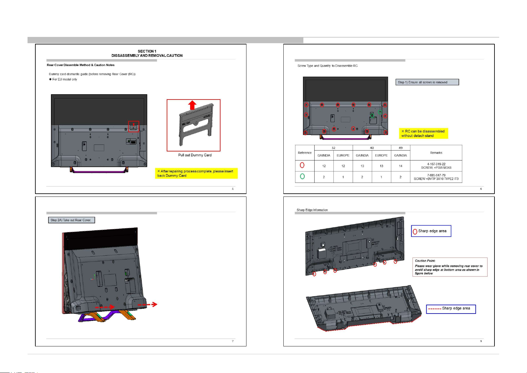
4. Metal Washer (Flat) or Coin (for remove Rear Cover)
5. Ruler (for remove Rear Cover)
2 OPTIONAL EQUIPMENT
TOOLS & EQUIPMENTS
Thickness: approx. 1.5mm
Diameter: 20~25mm
(wrap in tape (L=50mm))
1. Screwdriver (e.g. #0 Phillips Screwdriver)
2. Parts Tray for loose screws and small items
3. Flashlight
For Surface Mounted Parts/Connectors;
Hot-Air Type soldering Iron is needed.
Plastic or Metal Ruler
(In case of Metal ruler, wrap
in tape (L=50mm) for prevent
scratches)
3
Page 4
DISSASSEMBLY
4
Page 5
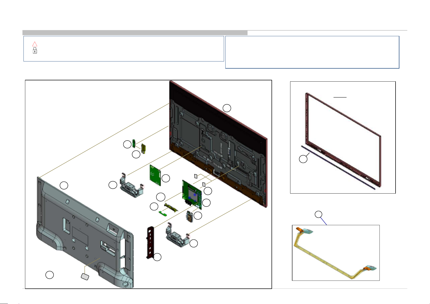
DISASSEMBLY, EXPLODED VIEWS AND OTHER PARTS
•Place the TV set facing downwards on a stable, level surface before disassembly and assembly of parts.
!
• and shaded parts are critical for safety. Replace only with part number specified.
• Parts contain confidential information. Strictly follow the instruction whenever the components are
repaired and/or replaced.
3-1. KDL-32W61*
3-1-1. Disassembly, Exploded View
SWITCH UNIT
4
REAR
COVER
BRACKET
SWITCH
2
7
LOUD
SPEAKER
5
HKT-E MOUNT
LK1 BRD
14
GUIDE, LIGHT
10
9
12
11
UNIVERSAL
SIL-TU
SHEET,
13
THERMAL (BM)
BLM BOARD
(*) Parts are not stocked since they are seldom required for routine service.
Some delays should be anticipated when ordering these components.
Picture provided in this section might have slight difference from the actual sets.
Lines that indicate parts are shown in blue in the illustration.
The reference number beside the part description indicates the disassembly sequence.
Remove screws before disassembly. Unplug connectors before disassembly
BEZEL
P-MOD
15
16
PANEL,
ORNAMENT (MZT)
STAND, ASSY
51
LABEL, UNDER
1
TERMINAL
BRACKET, SIDE (FRE)
3
7
LOUDSPEAKER
5
Page 6
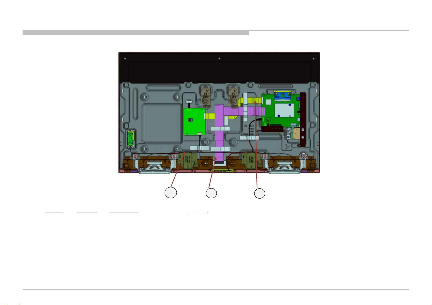
SOURCE BOARD (1)
CN9901(LK1) (1)
SP (1)
HARNESS/CABLE
REF. NO. PART NO. DESCRIPTION REMARKS
81
82
83
1-912-036-11 FLEXIBLE FLAT CABLE 30P CN8501(BLM)-
1-849-993-11 FLEXIBLE FLAT CABLE 40P CN9601(BLM)-
1-910-805-95 HARNESS ASSY CN9602(BLM)-CN100(HKT)-CN1(3KEY)/CN4001(LK1)-
83
81
82
KDL-32W6100/6103/6105 (CEI)
KDL-32W6100/6103/6105 (CEI)
6
Page 7
PARTS LIST
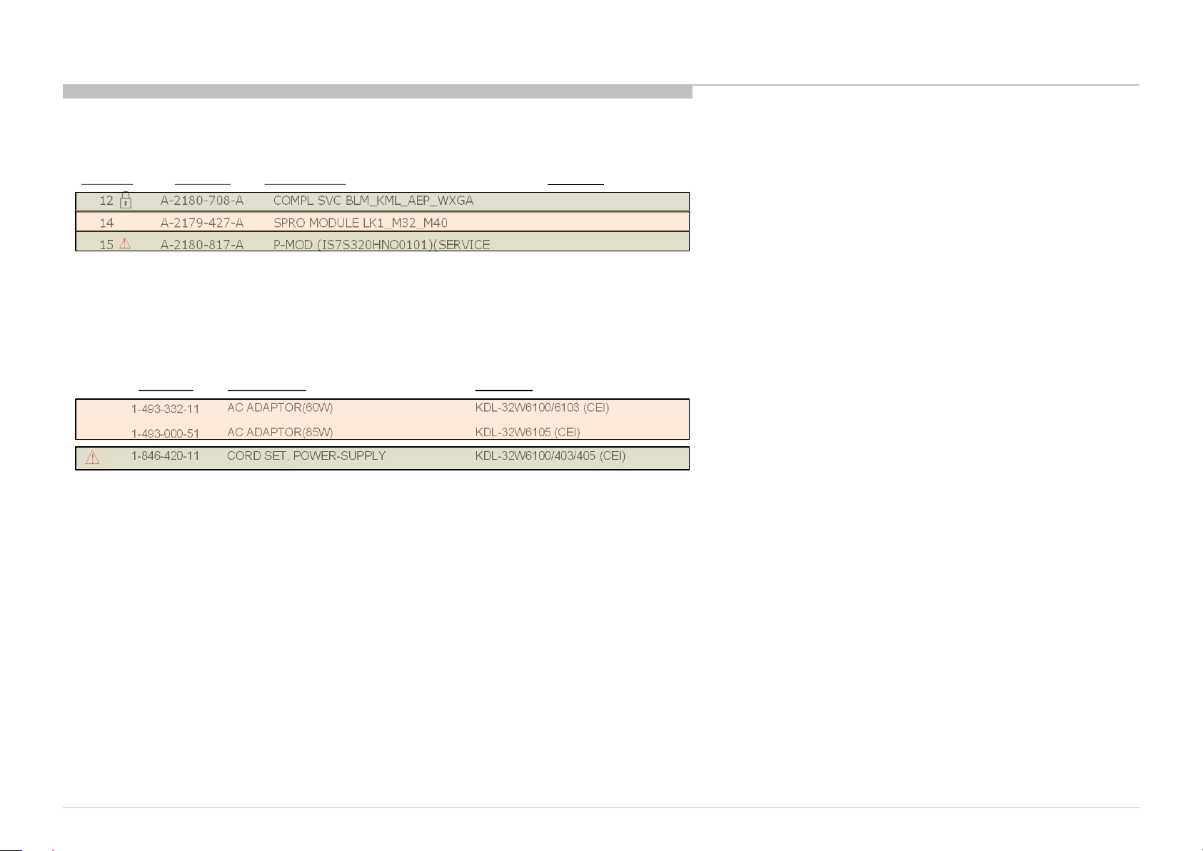
SET PART LIST
REF. NO. PART NO. DESCRIPTION REMARKS
12 A-2180-708-A COMPL SVC BLM_KML_AEP_WXGA
14 A-2179-427-A SPRO MODULE LK1_M32_M40
!
15 A-2180-817-A P-MOD (IS7S320HNO0101)(SERVICE
Other Parts
PART NO. DESCRIPTION REMARKS
1-493-332-11
1-493-000-51
1-846-420-11 CORD SET, POWER-SUPPLY KDL-32W6100/403/405 (CEI)
!
AC ADAPTOR(60W) KDL-32W6100/6103 (CEI)
AC ADAPTOR(85W) KDL-32W6105 (CEI)
Printed Circuit Board, incl. capacitors
Printed Circuit Board, incl. capacitors
Liquid Crystal Display
External Power Supply
Cable
7
Page 8

9-888-729-E4
Sony Home Entertainment & Sound Products Inc.
English
© 2021.02
8
 Loading...