

Page 1
SERVICE MANUAL
HISTORY INFORMATION FOR THE FOLLOWING MANUAL:
SERVICE MANUAL
AZ1-L Chassis
ORIGINAL MANUAL ISSUE DATE: 8/2010
Version Date Subject
1.0 8/3/2010 No revisions or updates are applicable at this time.
LCD Digital Color TV
9-888-357-01
Page 2

SERVICE MANUAL
SERVICE MANUAL
AZ1-L Chassis
Self Diagnosis
Supported model
LCD Digital Color TV
9-888-357-01
Page 3
MODEL LIST
MODEL COMMANDER DESTINATION MODEL COMMANDER DESTINATION
KDL-32EX717 RM-YD047 Columbia
KDL-46EX717 RM-YD047 Columbia
KDL-40EX717 RM-YD047 Columbia
KDL-55EX717 RM-YD047 Columbia
9-888-357-01
Page 4

TABLE OF CONTENTS
Specifi cations..................................................................................................................................................................................1
Warnings and Cautions ..................................................................................................................................................................3
Safety-Related Warning ..................................................................................................................................................................4
Safety Check-Out ............................................................................................................................................................................5
Self Diagnosis Functions ...............................................................................................................................................................7
SEC 1. Disassembly/Part Number Information ..........................................................................................................................11
1-1. Table-Top Stand Assembly Removal .............................................................................................................................11
1-2. Rear Cover, Under Cover, Vesa Brackets, AC Inlet, Switch Unit and Power Switch Removal......................................12
1-2-1. KDL-32EX717/40EX717/46EX717 Only .................................................................................................................................... 12
1-2-2. KDL-55EX717 Only .................................................................................................................................................................... 13
1-3. Speakers, Speaker Brackets, Bottom Frame and HLR Board Removal .......................................................................16
1-4. GE3C/GE3A/GE2B (Power) Boards, BAL Board, HMS2 Board, Lens and
Panel Removal ..............................................................................................................................................................17
1-4. Cleaning the LCD Panel ...............................................................................................................................................18
1-5. Screw Legend................................................................................................................................................................18
1-6. Connectors ....................................................................................................................................................................18
1-7. Accessories and Packaging ..........................................................................................................................................19
1-8. Miscellaneous ................................................................................................................................................................19
1-9. Remote Commander .....................................................................................................................................................19
1-10. Wire Dressing ................................................................................................................................................................20
1-10-1. KDL-32EX717 Only .................................................................................................................................................................... 20
1-10-2. KDL-40EX717 Only .................................................................................................................................................................... 20
1-10-3. KDL-46EX717 Only .................................................................................................................................................................... 20
1-10-4. KDL-55EX717 Only .................................................................................................................................................................... 20
KDL-32EX717/40EX717/46EX717/55EX717 i
Page 5

TABLE OF CONTENTS
SEC 2. Service Adjustments ........................................................................................................................................................21
2-1. Accessing Service Adjustment Mode ............................................................................................................................21
2-1-1. Viewing the Service Menus ........................................................................................................................................................ 22
2-1-2. Using the Remote Commander to View or Change Service Data ............................................................................................. 22
2-2. Adjustments After Replacing the BAL Board or LCD Panel ..........................................................................................23
2-2-1. Updating the Software ............................................................................................................................................................... 23
2-2-2. Selecting the Model ................................................................................................................................................................... 23
2-2-3. Setting the Destination ............................................................................................................................................................... 24
2-2-4. Verifying the Model and Panel Information ................................................................................................................................ 25
2-2-5. Reconnecting All Cables ............................................................................................................................................................ 26
2-3. White Balance Adjustments ...........................................................................................................................................26
2-4. Resetting the TV to Factory Condition ...........................................................................................................................27
2-4-1. Resetting the TV to Factory Condition Using Service Mode ...................................................................................................... 27
SEC 3. Diagrams ...........................................................................................................................................................................28
3-1. Circuit Boards Location .................................................................................................................................................28
3-2. Block Diagram ...............................................................................................................................................................29
KDL-32EX717/40EX717/46EX717/55EX717 ii
Page 6
SPECIFICATIONS
Nombre del modelo KDL- 55EX717 46EX717 40EX717 32EX717
Sistema
Sistema de TV Análogo: NTSC 3.58
Cobertura de canales VHF: 2-13, UHF: 14-69
Sistema del panel Panel LCD (pantalla de cristal líquido)
Salida de bocinas 10 W + 10 W
Digital: DVB-T
CATV (Análogo): 1-125
Tomas de entrada/salida
CABLE/ANTENNA
(Cable/Antena)
VIDEO IN 1/2/3
(Entrada de video 1/2/3)
COMPONENT IN 1
(Entrada de componente 1
HDMI IN 1/2/3/4
(Entrada HDMI 1/2/3/4)
AUDIO OUT (Salida de audio) 500 mVrms (típico)
AURICULAR Minitoma estéreo
DIGITAL AUDIO OUT (OPTICAL)
(Salida de audio digital óptica)
PC IN (Entrada de PC) Subminiatura D de 15 contactos, RGB anal
PC/HDMI 4 AUDIO IN
(Entrada de audio de PC/HDMI 4)
LAN
USB/DLNA Consulte el i-Manual para el formato compatible.
* Para conexiones LAN, utilice un cable 10BASE-T/100BASE-TX de categoría 7 (no se suministra).
/2
Terminal externo de 75 ohms para entrada de señal de radiofrecuencia
VIDEO / AUDIO
BPR (video componente)
YP
Formato de señal:
/2
)
AUDIO
HDMI:
Video:
Audio: PCM lineal de dos canales 32; 44,1 y 48 kHz, 16, 20 y 24 bits, Dolby Digital
AUDIO (HDMI IN 4)
Señal de audio óptica digital PCM/Dolby Digital
Minitoma estéreo
Conector 10BASE-T/100BASE-TX
(La velocidad de la conexión podría variar en función del entorno de red. No se garantizan la tasa de
comunicación ni la calidad de comunicación 10BASE-T/100BASE-TX para este TV.)*
480i, 480p, 720p, 1080i, 1080p
480i, 480p, 720p, 1080i, 1080p, 1080/24p
ó
gico
Macintosh es una marca comercial de Apple Inc., registrada en EE. UU. y otros países.
HDMI, el logotipo de HDMI y High-Definition Multimedia Interface son marcas
coerciales o marcas comerciales registradas de HDM
Licensing, LLC. en EE. UU. y en otros países.
Fergason Patent Properties, LLC:
Nº de patente de EE. UU. 5.717.422
Nº de patente de EE. UU. 6.816.141
Fabricado bajo licencia de Dolby Laboratories. Dolby y el símbolo
de la doble D son marcas comerciales de Dolby Laboratories.
Blu-ray Disc es una marca comercial.
“BRAVIA” y , S-Force, Motionflow, BRAVIA Sync y son marcas
comerciales o marcas registradas de Sony Corporation.
“XMB” y “xross media bar” son marcas comerciales registradas de
Sony Corporation y Sony Computer Entertainment Inc.
“PlayStation” es una marca comercial registrada y “PS3” es una marca comercial
de Sony Computer Entertainment Inc.
DLNA
, el logotipo de DLNA y DLNA CERTIFIED
®
marcas de servicio o marcas de certificación de Digital
Living Network Alliance.
® son marcas comerciales
KDL-32EX717/40EX717/46EX717/55EX717 1
Page 7
Nombre del modelo KDL- 55EX717 46EX717 40EX717 32EX717
Alimentación y otras especificaciones
Requisitos de alimentación 110-240 V ca, 50/60 Hz
Consumo energético
en uso
1
en DAM*
Tamaño de pantalla
(medido diagonalmente)
Bocina
Gama completa con parlantes
Dimensiones con soporte
Peso con soporte (kg) 26,1 18,6 15,4 10,8
Accesorios suministrados
Accesorios opcionales Cables de conexión / Kit de correa de soporte
*1 El modo de adquisición de descarga (DAM) se utiliza para actualizaciones de software.
*2 En algunas regiones o países, es posible que el soporte de montaje para pared (SU-WL500) no esté disponible.
• La disponibilidad de los accesorios opcionales dependerá de las existencias.
• El diseño y las especificaciones están sujetos a cambios sin previo aviso.
sin soporte
patrón de orificios de montaje
mural
(mm)
tamaño de tornillos de montaje
mural
(mm)
sin soporte
Soporte de montaje mural*
(cm)
(pulgadas)
(mm)
(2)
(mm) 1.278 × 797 × 350 1.085 × 688 × 260 952 × 613 × 250 764 × 507 × 250
(mm) 1.278 × 765 × 73 1.085 × 656 × 75 952 × 581 × 74 764 × 475 × 74
(kg) 21,8 16,3 13,2 8,8
2
138 W 115 W 109 W 63 W
15 W (Se puede oír
un ruido durante la
descarga pero es
normal.)
138,8
55
Consulte “Verificación de los accesorios”.
(Se puede oír un ruido durante la descarga pero es normal.)
116,8
46
34 × 160
M6
SU-WL500
13 W
W 2,0 ed soneMarepse ne
101,6
40
80,1
31,5
(32 clase)
)lacitrev( saeníl 080.1 × )latnoziroh( sotnup 029.1 rotinom led nóiculoseR
SPECIFICATIONS
Verificación de los
accesorios
Cable de alimentación de ca (1)
Soporte de sobremesa (1)*
Cubierta posterior del soporte (1)*
Cómo fijar tornillos para el soporte
de sobremesa (M5 × 16) (4)
Cómo montar tornillos para el
soporte de sobremesa (M5 × 16) (4)
(para los modelos KDL-40/32EX717)
Control remoto (1)*
3
Pilas de tamaño AAA (2)
002 × 002003 × 003003 × 004
*1Los modelos 32" y 40" requieren montaje.
Consulte el otro folleto para ensamblar el
soporte.
2
La cubierta posterior del soporte se encuentra
*
sujetada al soporte de sobremesa, a excepción
del modelos de 46" y 55" pulgadas.
3
Consulte el nombre del modelo impreso en el
*
control remoto.
1
2
KDL-32EX717/40EX717/46EX717/55EX717 2
Page 8
WARNINGS AND CAUTIONS
CAUTION
These servicing instructions are for use by qualifi ed service personnel only. To reduce the risk of electric shock, do not perform any servicing
other than that contained in the operating instructions unless you are qualifi ed to do so.
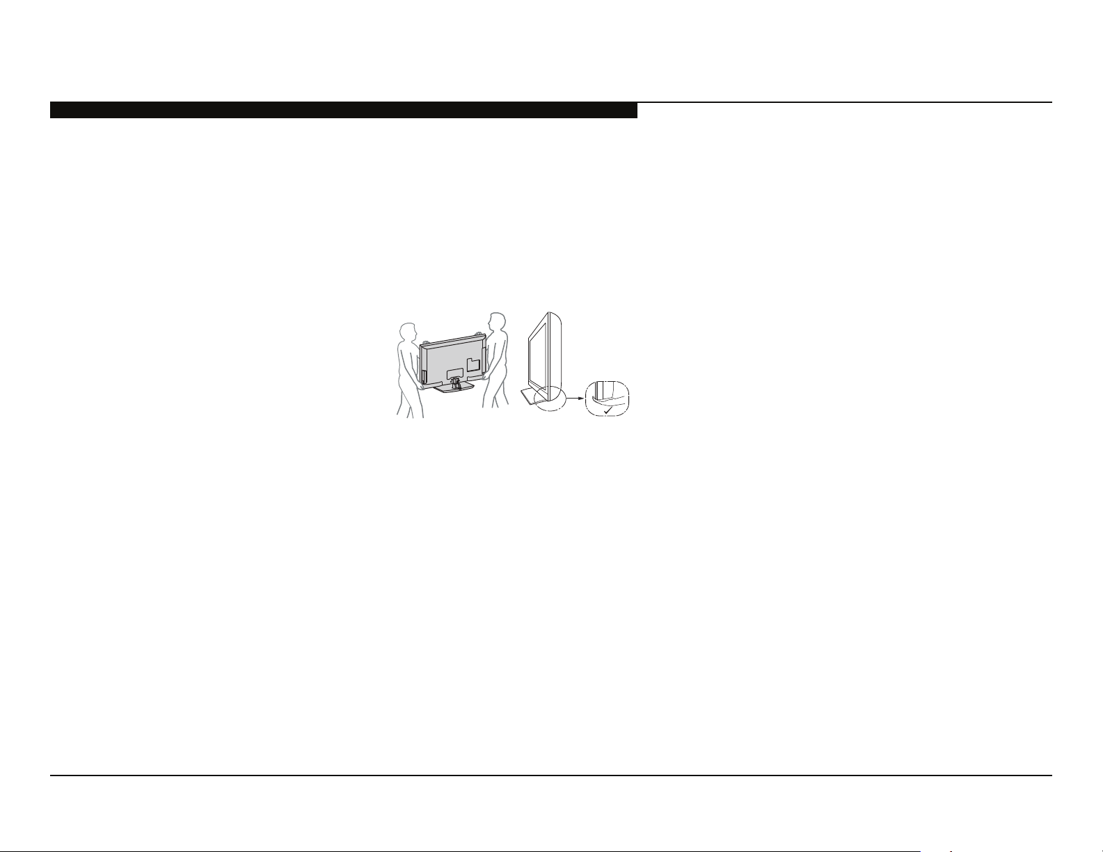
CARRYING THE TV
• Carry the TV with the adequate number of people; larger size TVs require two or more people.
• Correct hand placement while car rying the TV is very importa nt for safety and to avoid
damage.
WARNING!!
An isolation transformer should be used during any service to avoid possible shock hazard, because of live chassis. The chassis of this
receiver is directly connected to the AC power line.
! SAFETY-RELATED COMPONENT WARNING!!
Components identifi ed by shading and ! mark on the exploded views are critical for safe operation.
Replace all components with Sony parts whose part numbers appear as shown in this manual or in supplements published by Sony. It is
essential that all critical parts be replaced only with the part number specifi ed in this manual to prevent electric shock, fi re, or other hazard.
Circuit adjustments that are critical for safe operation are identifi ed in this manual.
Follow these procedures whenever critical components are replaced or improper operation is suspected.
NOTE: Do not modify the original design without obtaining written permission from the manufacturer or you will void the original parts and
labor guarantee.
KDL-32EX717/40EX717/46EX717/55EX717 3
Page 9

SAFETY-RELATED WARNING
USE CAUTION WHEN HANDLING THE LCD PANEL
When repairing the LCD panel, be sure you are grounded by using a wrist band.
When installing the LCD panel on a wall, the LCD panel must be secured using the 4 mounting holes on the rear cover.
1) Do not press on the panel or frame edge to avoid the risk of electric shock.
2) Do not scratch or press on the panel with any sharp objects.
3) Do not leave the module in high temperatures or in areas of high humidity for an extended period of time.
4) Do not expose the LCD panel to direct sunlight.
5) Avoid contact with water. It may cause a short circuit within the module.
6) Disconnect the AC power when replacing the inverter circuit.
(High voltage occurs at the inverter circuit at 650Vrms.)
7) Always clean the LCD panel with a soft cloth material.
8) Use care when handling the wires or connectors of the inverter circuit. Damaging the wires may cause a short.
9) Protect the panel from ESD to avoid damaging the electronic circuit (C-MOS).
10) During the repair, DO NOT leave the Power On for more than 1 hour while the TV is face down on a cloth.
KDL-32EX717/40EX717/46EX717/55EX717 4
Page 10
SAFETY CHECK-OUT
After correcting the original service problem, perform the following safety checks before releasing the set to the customer:
1. Check the area of your repair for unsoldered or poorly soldered connections.
Check the entire board surface for solder splashes and bridges.
2. Check the interboard wiring to ensure that no wires are “pinched” or touching
high-wattage resistors.
3. Check that all control knobs, shields, covers, ground straps, and mounting
hardware have been replaced. Be absolutely certain that you have replaced
all the insulators.
4. Look for unauthorized replacement parts, particularly transistors, that were
installed during a previous repair. Point them out to the customer and
recommend their replacement.
5. Look for parts which, though functioning, show obvious signs of deterioration.
Point them out to the customer and recommend their replacement.
6. Check the line cords for cracks and abrasion. Recommend the replacement
of any such line cord to the customer.
7. Check the antenna terminals, metal trim, “metallized” knobs, screws, and
all other exposed metal parts for AC leakage. Check leakage as described
below.
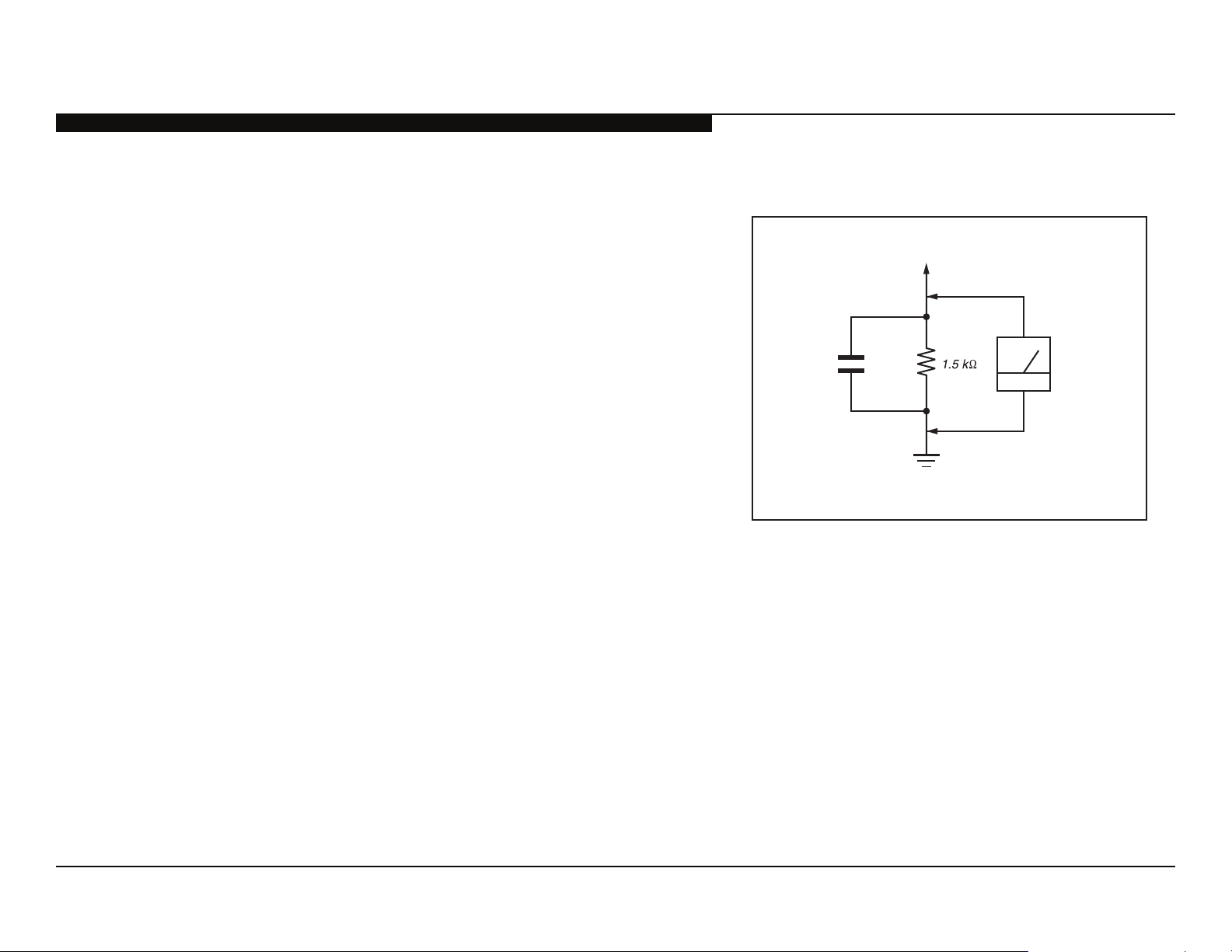
To Exposed Metal
Parts on Set
AC
0.15 μF
Earth Ground
Figure A. Using an AC voltmeter to check AC leakage.
Voltmeter
(0.75V)
KDL-32EX717/40EX717/46EX717/55EX717 5
Page 11
LEAKAGE TEST
The AC leakage from any exposed metal part to earth ground and from all
exposed metal parts to any exposed metal part having a return to chassis, must
not exceed 0.5 mA(500 microamperes). Leakage current can be measured by
any one of three methods.
1. A commercial leakage tester, such as the Simpson 229 or RCA WT-540A.
Follow the manufacturers’ instructions to use these instructions.
2. A battery-operated AC milliampmeter. The Data Precision 245 digital
multimeter is suitable for this job.
3. Measuring the voltage drop across a resistor by means of a VOM or batteryoperated AC voltmeter. The “limit” indication is 0.75 V, so analog meters
must have an accurate low voltage scale.
The Simpson’s 250 and Sanwa SH-63TRD are examples of passive VOMs
that are suitable. Nearly all battery-operated digital multimeters that have a
2 VAC range are suitable (see Figure A).
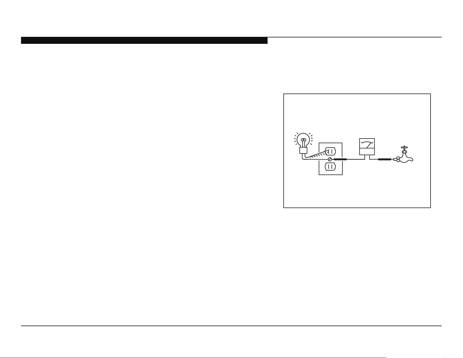
HOW TO FIND A GOOD EARTH GROUND
A cold-water pipe is a guaranteed earth ground; the cover-plate retaining screw
on most AC outlet boxes is also at earth ground.
SAFETY CHECK-OUT
Trouble Light
AC Outlet Box
Ohmmeter
Cold-water Pipe
If the retaining screw is to be used as your earth ground, verify that it is at
Figure B. Checking for earth ground.
ground by measuring the resistance between it and a cold-water pipe with an
ohmmeter. The reading should be zero ohms.
If a cold-water pipe is not accessible, connect a 60-to 100-watt trouble-light (not
a neon lamp) between the hot side of the receptacle and the retaining screw.
Try both slots, if necessary, to locate the hot side on the line; the lamp should
light at normal brilliance if the screw is at ground potential (see Figure B).
KDL-32EX717/40EX717/46EX717/55EX717 6
Page 12

SELF DIAGNOSIS FUNCTIONS
R
SELF DIAGNOSIS FUNCTION
The units in this manual contain a self-diagnostic function. If an error occurs, the STANDBY LED will automatically begin to fl ash. The number
of times the LED fl ashes translates to a probable source of the problem. A defi nition of the STANDBY LED fl ash indicators is listed in the
instruction manual for the user’s knowledge and reference. If an error symptom cannot be reproduced, the remote commander can be used to
review the failure occurrence data stored in memory to reveal past problems and how often these problems occur.
DIAGNOSTIC TEST INDICATORS
When an error occurs, the STANDBY LED will fl ash a set number of times to indicate the possible cause of the problem. If there is more than
one error, the LED will identify the fi rst of the problem areas.
Result for all of the following diagnostic items are displayed on screen.
If the screen displays a “0”, no error has occurred .
Self Diagnosis
Supported model
Diagnostic
Item
RGB_SEN RGB Sensor ACK Error
MAIN_POWE
DC_ALERT DC Alert
DTT-WDT DTT Error
AUD_PROT Audio Error Detection
BALANCER Panel Balancer Error
TCON ERR TCON Error
HFR ERR HFR Error
P_ID_ERR Panel ID NVM Error
BACKLITE Backlight Error
TEMP_ERR Temperature Error
FAN_ERR
Diagnostic Item
Description
Main Power
Over Voltage Protection
Fan Error
(Not Used in these models)
Number of times
Standby LED blinks
NA
2
3
4
5
6
7
Possible Location
NA
GE2B (Power) Board (KDL-55EX717 Only)
GE3A (Power) Board (KDL-40EX717/46EX717 Only)
GE3C (Power) Board (KDL-32EX717 Only)
BAL Board
BAL Board
GE2B (Power) Board (KDL-55EX717 Only)
GE3A (Power) Board (KDL-40EX717/46EX717 Only)
GE3C (Power) Board (KDL-32EX717 Only)
BAL Board
BAL Board
LCD Panel
TCON Control MT Board
BAL Board
BAL Board
HLR Board
NA
KDL-32EX717/40EX717/46EX717/55EX717 7
Page 13

STANDBY LED FLASH COUNT
SELF DIAGNOSIS FUNCTIONS
2 times
5 times
Ambient Sensor/
(IR) Infrared Receiver
Picture Off /
Timer LED
Standby LED Power LED
LED ON 0.3 sec.
LED OFF 0.3 sec.
LED OFF
3 sec.
KDL-32EX717/40EX717/46EX717/55EX717 8
Page 14

VIEWING THE SELF CHECK DIAGNOSTIC LIST
For errors with symptoms such as “power sometimes shuts off” or “screen sometimes goes out” that cannot be confi rmed, it is possible to
bring up past occurrences of a failure for confi rmation on the Self Check diagnostic screen:
1. TV must be in standby mode. (Power off).
2. Press the following buttons on the Remote Commander within a second of each other:
SELF DIAGNOSIS FUNCTIONS
DISPLAY
Channel 5 Volume -
* NOTE: This differs from accessing Service Adjustments Mode (Volume +)
SELF CHECK
000 RGB_SEN
002 MAIN_POWE
003 DC_ALERT1
003 AUD_PROT
003 DTT_WDT
004 BALANCER
005 HFR_ERR
005 TCON_ERR
005 P_ID_ERR
006 BACKLITE
007 TEMP_ERR
007 FAN_ERR
010 RESERVED
011 RESERVED
12345-00333-0678912345-00333-06789--
-------------- -------------- -------------- 00
0501210811 0412311234 0311111825 00
-------------- -------------- -------------- 00
-------------- -------------- -------------- 00
-------------- -------------- -------------- 00
-------------- -------------- -------------- 00
-------------- -------------- -------------- 00
-------------- -------------- -------------- 00
-------------- -------------- -------------- 00
-------------- -------------- -------------- 00
-------------- -------------- -------------- 00
-------------- -------------- -------------- 00
-------------- -------------- -------------- 00
-------------- -------------- -------------- 00
POWER
.
StandBy LED Flash Count
Diagnostic Item
Error history (Most recent time the failure occurred)
Error history (Failure time before the last occurrence)
Error history (Failure time before the 2
Error Count (00-99)
Panel operation time by hour (MAX:65535)
Panel operation time by hour (MAX:65535)
Boot count (MAX:65535)
Boot count (MAX:65535)
Total operation time by hour (MAX:65535)
Total operation time by hour (MAX:65535)
nd
to last occurrence)
KDL-32EX717/40EX717/46EX717/55EX717 9
Page 15

SELF DIAGNOSIS FUNCTIONS
CLEARING THE SELF CHECK DIAGNOSTIC LIST
Since the diagnostic results displayed on the screen are not automatically cleared, always check the self-diagnostic screen after you have
completed the repairs to be sure you have cleared the result display to “0”.
1. To clear the Error history and Error count: Press the Channel 8 Channel 0.
2. To clear the Panel operation time: Press the Channel 7 Channel 0.
EXITING THE SELF CHECK DIAGNOSTIC SCREEN
1. To exit the Self Diagnostic screen, turn off the power to the TV by pressing the POWER button on the remote or the POWER button on
the TV.
KDL-32EX717/40EX717/46EX717/55EX717 10
Page 16

SEC 1. DISASSEMBLY/PART NUMBER INFORMATION
1-1. TABLE-TOP STAND ASSEMBLY REMOVAL
A
Remove 4 screws from Table-Top Stand Assembly
B
Lift up TV set to detach from Table-Top Stand Assembly
Components not identifi ed by a part number or
description are not stocked because they are seldom
required for routine service.
NOTE: The components identifi ed by shading
and ! mark are critical for safety. Replace only
with part number specifi ed.
A
B
The component parts of an assembly are indicated by the
reference numbers in the far right column of the parts list
and within the dotted lines of the diagram.
NOTE: The components identifi ed by a red outline and a mark contain
confi dential information. Specifi c instructions must be adhered to whenever
these components are repaired and/or replaced.
See Appendix A: Encryption Key Components in the back of this manual.
2
Items marked with an asterisk are not stocked since
*
they are seldom required for routine service. Expect
some delay when ordering these components.
1
C
Gently place the TV set face down onto a soft cloth
C
Soft Cloth
3
5
REF. NO. PART NO. DESCRIPTION [ASSEMBLY INCLUDES] REF. NO. PART NO. DESCRIPTION [ASSEMBLY INCLUDES]
1 X-2547-875-1 BASE (M3A) ASSEMBLY
(KDL-32EX717/40EX717 ONLY)
1 X-2547-878-1 BASE (L3C) ASSEMBLY
(KDL-46EX717 ONLY)
1 X-2547-877-1 BASE (LL3A) ASSEMBLY
(KDL-55EX717 ONLY)
2 4-170-477-01 COVER, NECK (M3A FRONT)
(KDL-32EX717/40EX717/46EX717 ONLY)
2 4-187-664-01 COVER, NECK (LL3A FRONT)
(KDL-55EX717 ONLY)
3 4-170-485-01 COVER, NECK (M3A REAR)
(KDL-32EX717/40EX717/46EX717 ONLY)
3 4-187-665-01 COVER, NECK (LL3A REAR)
(KDL-55EX717 ONLY)
4
4 4-170-449-01 NECK (M3A)
(KDL-32EX717 ONLY)
4 4-170-450-11 NECK (ML3A)
(KDL-40EX717/46EX717 ONLY)
4 4-170-451-01 NECK (LL3A)
(KDL-55EX717 ONLY)
5 2-580-608-01 SCREW, +PSW M5X16
(SCREWS TO ATTACH TABLE-TOP STAND TO LCD TV)
For product protection and safety reasons, Sony strongly recommends
that you use the screws provided with the TV
CAUTION: These screws cannot be used to secure the TV to the
Wall Mount Brackets
2-580-608-01 SCREW, +PSW M5X16
KDL-32EX717/40EX717/46EX717/55EX717 11
Page 17

DISASSEMBLY/PART NUMBER INFORMATION
1-2. REAR COVER, UNDER COVER, VESA BRACKETS, AC INLET, SWITCH UNIT AND
POWER SWITCH REMOVAL
1-2-1. KDL-32EX717/40EX717/46EX717 ONLY
A
Remove 4 screws from Rear Cover to detach from
Bezel and Under Cover
B
Remove 4 screws from Rear Cover to detach from LCD
Panel and Bottom Frame
C
Remove 1 screw from Rear Cover to detach from
Terminal Area
D
Remove 1 screw from Rear Cover to detach from
Side Jack Area
E
Remove screws from Rear Cover to
detach from Panel Brackets
4 from KDL-32EX717/40EX717 Only
6 from KDL-46EX717 Only
F
Carefully lift Rear Cover from bottom
side to detach from Bezel
G
Disconnect AC Inlet from GE3C/GE3A
(Power) Boards and release 2 clips
to detach from Under Cover
H
Remove 1 screw from Under Cover to
detach from Bottom Frame
I
Slide-out Vesa Brackets to detach from
Rear Cover
I
J
K
H
NOTE: The components identifi ed by shading
!
mark are critical for safety. Replace only
and
with part number specifi ed.
G
56
F
E
D
57
NOTE: The components identifi ed by a red outline and a mark contain
confi dential information. Specifi c instructions must be adhered to whenever
these components are repaired and/or replaced.
See Appendix A: Encryption Key Components in the back of this manual.
53
54
55
52
51
J
Lift up Switch Unit and disconnect 1 connector to
C
remove from LCD Panel
K
Slide-out Power Switch and disconnect 1 connector
to remove from Switch unit
Note: The Vesa Brackets are not included with the
Rear Cover and must be reattached to the
replacement Rear Cover.
A
B
REF. NO. PART NO. DESCRIPTION [ASSEMBLY INCLUDES] REF. NO. PART NO. DESCRIPTION [ASSEMBLY INCLUDES]
51 4-176-751-11 REAR COVER (32)
(KDL-32EX717 ONLY)
51 4-176-752-11 REAR COVER (40)
(KDL-40EX717 ONLY)
51 4-176-753-12 REAR COVER (46)
(KDL-46EX717 ONLY)
52 3-297-324-02 COVER, ECS
! 53 1-842-031-11 AC INLET (2P)
54 4-176-838-21 COVER, UNDER (32)
(KDL-32EX717 ONLY)
54 4-184-861-11 COVER, UNDER (40)
(KDL-40EX717/46EX717 ONLY)
55 4-168-272-01 BRACKET, VESA (S)
(KDL-32EX717/40EX717/46EX717 ONLY)
56 1-487-804-11 SWITCH UNIT
57 1-798-309-11 POWER SWITCH
4-159-298-01 SCREW, +PSW M4X10
7-685-648-79 SCREW, +BVTP 3X12 TYPE2 IT-3
2-580-640-01 SCREW, +BVTP 4X16 TYPE2 IT-3
KDL-32EX717/40EX717/46EX717/55EX717 12
Page 18

DISASSEMBLY/PART NUMBER INFORMATION
1-2-2. KDL-55EX717 ONLY
CAUTION: The 55 inch model uses a Metal type Rear Cover. Use care when handling the
Rear Cover to avoid the sharp edges. Gloves are recommended when handling the Rear
Cover. For more information, refer to “Rear Cover Caution (KDL-55EX717 Only)” on page 14.
A
Refer to “Removing the Rear Cover (KDL-55EX717 Only)” on page 14.
Remove 10 screws from Rear Cover to detach from Bezel, Bottom Frame and
Under Cover
B
Remove 4 screws from Rear Cover to detach from Vesa Brackets
C
Remove 4 screws from Rear Cover to detach from LCD Panel
D
Remove 1 screw from Rear Cover to detach from Terminal Area
E
Remove 6 screws from Rear Cover to detach from Panel Brackets
F
Carefully lift Rear Cover from bottom side to detach from Bezel
G
Lift-up Hook Cover to detach from Under Cover
H
Disconnect AC Inlet from GE2B (Power) Board and release 2 clips to detach from
Under Cover
I
Remove 1 screw from Under Cover to detach from Bottom Frame
J
Remove 4 screws from Vesa Brackets to detach from LCD Panel
K
Lift up Switch Unit and disconnect 1 connector to remove
from LCD Panel
NOTE: The components identifi ed by shading
!
mark are critical for safety. Replace only
and
with part number specifi ed.
109
NOTE: The components identifi ed by a red outline and a mark contain
confi dential information. Specifi c instructions must be adhered to whenever
these components are repaired and/or replaced.
See Appendix A: Encryption Key Components in the back of this manual.
105
104
106
107
108
103
L
Slide-out Power Switch and disconnect
1 connector to remove from Switch unit
Note: The Vesa Brackets are not included
with the LCD Panel and must be reattached
to the replacement LCD Panel.
Note: To reattach the Rear Cover,
refer to “Reattaching the Rear Cover
KDL-55EX717 Only)” on page 15.
(
H
101
G
J
K
L
B
A
I
F
REF. NO. PART NO. DESCRIPTION [ASSEMBLY INCLUDES] REF. NO. PART NO. DESCRIPTION [ASSEMBLY INCLUDES]
E
D
C
101 X-2547-039-2 REAR COVER ASSEMBLY (55)
102 4-171-318-01 LABEL, REAR TERMINAL
103 3-297-324-02 COVER, ECS
104 4-180-932-01 COVER, HOOK (55)
! 105 1-842-031-21 AC INLET (2P)
106 X-2549-472-1 COVER, UNDER (55) ASSEMBLY
107 4-176-944-01 BRACKET, VESA T (ML)
108 1-487-804-11 SWITCH UNIT
109 1-798-309-11 POWER SWITCH
102
2-580-639-01 SCREW, +BVTP 4X12 TYPE2 IT-3
2-580-611-01 SCREW, +PSW M6X16
4-159-298-01 SCREW, +PSW M4X10
2-580-591-01 SCREW, +PSW M3X5
7-685-646-79 SCREW +BVTP 3X8 TYPE2 IT-3
KDL-32EX717/40EX717/46EX717/55EX717 13
Page 19

DISASSEMBLY/PART NUMBER INFORMATION
REAR COVER CAUTION (KDL-55EX717 ONLY)
Do Not Grab
(Control Button hole/Under Cover area/Side Jack hole)
OK to grab
OK to grab but areas
have sharp edges.
Use caution when
handling.
Do Not grab.
Areas marked with
Red have sharp
edges and can
easily bend.
NOTE: The components identifi ed by shading
!
mark are critical for safety. Replace only
and
with part number specifi ed.
NOTE: The components identifi ed by a red outline and a mark contain
confi dential information. Specifi c instructions must be adhered to whenever
these components are repaired and/or replaced.
See Appendix A: Encryption Key Components in the back of this manual.
REMOVING THE REAR COVER (KDL-55EX717 ONLY)
1.LiftupHookCovertocreateasmallgap
1.LiftupHookCovertocreateasmallgap
BetweentheRearCoverandtheSpeakerBracket.
BetweentheRearCoverandtheSpeakerBracket.
2.PulltheRearCoverfromthebottom.
2.PulltheRearCoverfromthebottom.
1
2
Gap
Use caution when
handling
(Note edge area)
3
3.HoldoutthebottomoftheRearCover.
3.HoldoutthebottomoftheRearCover.
4.Usingbothhands,gentlypulloutthebottomofthe
4.Usingbothhands,gentlypulloutthebottomofthe
coveruntilabout20degrees.
coveruntilabout20degrees.
5.PullthetopoftheRearCoverdownwardtorelease
5.PullthetopoftheRearCoverdownwardtorelease
thehooksatthetopedgeoftheBezel.
thehooksatthetopedgeoftheBezel.
5
20
4
KDL-32EX717/40EX717/46EX717/55EX717 14
Page 20

DISASSEMBLY/PART NUMBER INFORMATION
REATTACHING THE REAR COVER (KDL-55EX717 ONLY)
1. AlignandinserttheholesofRearCoverwiththe
1. AlignandinserttheholesofRearCoverwiththe
hooksatthetopedgeoftheBezel.
hooksatthetopedgeoftheBezel.
2. GentlypushtheRearCoverinthemiddleoftop
2. GentlypushtheRearCoverinthemiddleoftop
tosecureintothehooks.
tosecureintothehooks.
1
20
HookofBEZEL
2
NOTE: The components identifi ed by shading
!
mark are critical for safety. Replace only
and
with part number specifi ed.
NOTE: The components identifi ed by a red outline and a mark contain
confi dential information. Specifi c instructions must be adhered to whenever
these components are repaired and/or replaced.
See Appendix A: Encryption Key Components in the back of this manual.
HoleofREARCOVER
3
3.KeeptheRearCoveralignedatthetopwhile
3.KeeptheRearCoveralignedatthetopwhile
pushingthebottomclosed.
pushingthebottomclosed.
4.Confirmthescrewholesindicatedbeloware
4.Confirmthescrewholesindicatedbeloware
aligned,andreinsertthesescrewsfirst.(Holdthe
aligned,andreinsertthesescrewsfirst.(Holdthe
RearCoverwhilereplacingthescrewstoensurethe
RearCoverwhilereplacingthescrewstoensurethe
coverdoesnotslipdown.)
coverdoesnotslipdown.)
4
KDL-32EX717/40EX717/46EX717/55EX717 15
Page 21

DISASSEMBLY/PART NUMBER INFORMATION
1-3. SPEAKERS, SPEAKER BRACKETS, BOTTOM FRAME AND HLR BOARD REMOVAL
A
Remove screws from Speaker Bracket Right
1 from KDL-32EX717 Only
2 from all models except KDL-32EX717 Only
B
Lift up Speaker Bracket Right to detach from Bezel
C
Remove 2 screws from Speaker to detach from Speaker Bracket Right
D
Remove screws from Bottom Frame to detach from LCD Panel
3 from KDL-32EX717 Only
5 from KDL-40EX717/46EX717 Only
E
Lift-up Bottom Frame to detach from LCD Panel
F
Remove screws from Speaker Bracket Left
1 from KDL-32EX717 Only
2 from all models except KDL-32EX717 Only
G
Lift up Speaker Bracket Left to detach from Bezel
H
Remove 2 screws from Speaker to detach from Speaker Bracket Left
I
Disconnect 1 connector from HLR Board, then release clips and lift up to remove from LED Guide
NOTE: The components identifi ed by shading
!
mark are critical for safety. Replace only
and
with part number specifi ed.
152
NOTE: The components identifi ed by a red outline and a mark contain
confi dential information. Specifi c instructions must be adhered to whenever
these components are repaired and/or replaced.
See Appendix A: Encryption Key Components in the back of this manual.
152
154
153
151
H
REF. NO. PART NO. DESCRIPTION [ASSEMBLY INCLUDES] REF. NO. PART NO. DESCRIPTION [ASSEMBLY INCLUDES]
I
G
C
A
B
D
F
E
151 X-2548-470-1 BRACKET, SP R (32) ASSEMBLY
(KDL-32EX717 ONLY)
151 X-2548-514-1 BRACKET, SP R (40) ASSEMBLY
(KDL-40EX717 ONLY)
151 X-2548-516-1 BRACKET, SP R (46) ASSEMBLY
(KDL-46EX717 ONLY)
151 X-2548-518-1 BRACKET, SP R (55) ASSEMBLY
(KDL-55EX717 ONLY)
152 1-826-873-41 LOUDSPEAKER (3.4X17.5CM)
153 X-2548-469-1 BRACKET, SP L (32) ASSEMBLY
(KDL-32EX717 ONLY)
153 X-2548-513-1 BRACKET, SP L (40) ASSEMBLY
(KDL-40EX717 ONLY)
153 X-2548-515-1 BRACKET, SP L (46) ASSEMBLY
(KDL-46EX717 ONLY)
153 X-2548-517-1 BRACKET, SP L (55) ASSEMBLY
(KDL-55EX717 ONLY)
154 A-1744-405-A HLR BOARD, MOUNTED
2-580-639-01 SCREW, +BVTP 4X12 TYPE2 IT-3
(KDL-55EX717 ONLY)
2-580-640-01 SCREW, +BVTP 4X16 TYPE2 IT-3
(KDL-32EX717/40EX717/46EX717 ONLY)
KDL-32EX717/40EX717/46EX717/55EX717 16
Page 22

DISASSEMBLY/PART NUMBER INFORMATION
1-4. GE3C/GE3A/GE2B (POWER) BOARDS, BAL BOARD, HMS2 BOARD, LENS AND
PANEL REMOVAL
A
Remove 4 screws from GE3C/GE3A/GE2B (Power) Boards
B
Disconnect 6 connectors from GE3C/GE3A/GE2B (Power) Boards
C
Remove 4 screws from BAL Board
D
Disconnect 5 connectors from BAL Board
E
Slide Side Jack Bracket to right-side to remove from BAL Board
F
Slide Panel Brackets up, then out to detach from LCD Panel
4 from KDL-32EX717/40EX717 Only
6 from KDL-46EX717/55EX717 Only
G
Disconnect 1 connector from HMS2 Board and lift up to detach from Bezel
H
Release clips to detach Lens from HMS2 Board
I
Carefully Lift up LCD Panel to remove from Bezel
NOTE: The components identifi ed by shading
!
mark are critical for safety. Replace only
and
with part number specifi ed.
204
203
NOTE: The components identifi ed by a red outline and a mark contain
confi dential information. Specifi c instructions must be adhered to whenever
these components are repaired and/or replaced.
See Appendix A: Encryption Key Components in the back of this manual.
201
202
205
F
206
207
F
H
I
G
E
D
B
A
C
REF. NO. PART NO. DESCRIPTION [ASSEMBLY INCLUDES]
201 X-2549-619-2 BEZEL (32) ASSEMBLY
(KDL-32EX717 ONLY)
201 X-2549-620-2 BEZEL (40) ASSEMBLY
(KDL-40EX717 ONLY)
201 X-2549-617-2 BEZEL (46) ASSEMBLY
(KDL-46EX717 ONLY
201 X-2549-618-2 BEZEL (55) ASSEMBLY
(KDL-55EX717 ONLY)
202 A-1736-860-A HMS2 BOARD, MOUNTED
203 1-856-068-11 LENS
204 NA LCD PANEL
FOR ALL LCD PANEL PART NUMBER INFORMATION
REFER TO THE LCD PANELS SERVICE MANUAL
205 4-166-286-21 BRACKET, SIDE JACK
(KDL-32EX717/40EX717/46EX717 ONLY)
205 4-171-117-11 BRACKET, SIDE JACK M
(KDL-55EX717 ONLY)
REF. NO. PART NO. DESCRIPTION [ASSEMBLY INCLUDES]
206 A-1763-472-B BAL BOARD, COMPLETE
NOTE: For BAL Board replacement, please refer to section
2-2. Adjustments after Replacing the BAL Board or LCD Panel.
NOTE: Final software is not installed on this BAL Board.
Install the update after replacing this board using the instructions
provided with the software.
207 1-474-250-11 GE3C (POWER) BOARD, COMPLETE
(KDL-32EX717 ONLY)
207 1-474-213-11 GE3A (POWER) BOARD, COMPLETE
(KDL-40EX717/46EX717 ONLY)
207 1-474-212-11 GE2B (POWER) BOARD, COMPLETE
(KDL-55EX717 ONLY)
2-580-592-01 SCREW, +PSW M3X8
KDL-32EX717/40EX717/46EX717/55EX717 17
Page 23

DISASSEMBLY/PART NUMBER INFORMATION
1-4. CLEANING THE LCD PANEL
CAUTION: When cleaning the TV, be sure to unplug the power cord to avoid any chance of electric shock.
Clean the cabinet of the TV with a dry soft cloth.
ipe the LCD screen gently with a soft cloth.
W
Stubborn stains may be removed with a cloth slightly moistened with a solution of mild soap and warm water.
If using a chemically pretreated cloth, please follow the instruction provided on the package.
Never use strong solvents such as a thinner, alcohol or benzine for cleaning.
Periodic vacuuming of the ventilation openings is recommended to ensure the proper ventilation.
1-5. SCREW LEGEND
KDL-32EX717
P/N DESCRIPTION REMARKS TOTAL
2-580-639-01 SCREW, +BVTP 4X12 TYPE2 IT-3 NOT IN THIS MODEL 0
Š
2-580-611-01 SCREW, +PSW M6X16 NOT IN THIS MODEL 0
š
2-580-608-01 SCREW, +PSW M5X16 TABLE-TOP STAND(4), NECT to BASE(4) 8
Ť
2-580-592-01 SCREW, +PSW M3X8 BAL(4), GE3C(4) 8
ť
4-159-298-01 SCREW, +PSW M4X10 RC to PNL(2), RC to PNL BRKT(4), RC to BTM FRM(2), UC to BTM FRM(1), BTM FRM to PNL(3) 12
Ũ
2-580-591-01 SCREW, +PSW M3X5 NOT IN THIS MODEL 0
Ū
Ŭ
7-685-648-79 SCREW, +BVTP 3X12 TYPE2 IT-3 RC to SIDE JACK BRKT(1), RC to TRMNL AREA(1)
ŭ
7-685-646-79 SCREW, +BVTP 3X8 TYPE2 IT-3 NOT IN THIS MODEL
Ţ
2-580-640-01 SCREW, +BVTP 4X16 TYPE2 IT-3 RC to BEZ(2), RC to UC(2), SPKR BRKTS to BEZ(2), SPKR to SPKR BRKT-L(2), SPKR to SPKR BRKT-R(2)
NOTE: The components identifi ed by shading
!
mark are critical for safety. Replace only
and
with part number specifi ed.
NOTE: The components identifi ed by a red outline and a mark contain
confi dential information. Specifi c instructions must be adhered to whenever
these components are repaired and/or replaced.
See Appendix A: Encryption Key Components in the back of this manual.
1-6. CONNECTORS
254
CN6150
CN6151
TCON
GE3C
GE3A
GE2B
2
0
10
SWITCH UNIT
CN6003
253
CN2600
BAL
CN4300
CN3800
CN2561
CN2602
KDL-40EX717
P/N DESCRIPTION REMARKS TOTAL
2-580-639-01 SCREW, +BVTP 4X12 TYPE2 IT-3 NOT IN THIS MODEL 0
Š
2-580-611-01 SCREW, +PSW M6X16 NOT IN THIS MODEL 0
š
2-580-608-01 SCREW, +PSW M5X16 TABLE-TOP STAND(4), NECT to BASE(4) 8
Ť
2-580-592-01 SCREW, +PSW M3X8 BAL(4), GE3A(4) 8
ť
4-159-298-01 SCREW, +PSW M4X10 RC to PNL(2), RC to PNL BRKT(4), RC to BTM FRM(2), UC to BTM FRM(1), BTM FRM to PNL(5) 14
Ũ
2-580-591-01 SCREW, +PSW M3X5 NOT IN THIS MODEL 0
Ū
Ŭ
7-685-648-79 SCREW, +BVTP 3X12 TYPE2 IT-3 RC to SIDE JACK BRKT(1), RC to TRMNL AREA(1)
ŭ
7-685-646-79 SCREW, +BVTP 3X8 TYPE2 IT-3 NOT IN THIS MODEL
Ţ
2-580-640-01 SCREW, +BVTP 4X16 TYPE2 IT-3 RC to BEZ(2), RC to UC(2), SPKR BRKTS to BEZ(4), SPKR to SPKR BRKT-L(2), SPKR to SPKR BRKT-R(2)
KDL-46EX717
P/N DESCRIPTION REMARKS TOTAL
2-580-639-01 SCREW, +BVTP 4X12 TYPE2 IT-3 NOT IN THIS MODEL 0
Š
2-580-611-01 SCREW, +PSW M6X16 NOT IN THIS MODEL 0
š
2-580-608-01 SCREW, +PSW M5X16 TABLE-TOP STAND(4), NECT to BASE(4) 8
Ť
2-580-592-01 SCREW, +PSW M3X8 BAL(4), GE3A(4) 8
ť
4-159-298-01 SCREW, +PSW M4X10 RC to PNL(2), RC to PNL BRKT(6), RC to BTM FRM(2), UC to BTM FRM(1), BTM FRM to PNL(5) 16
Ũ
2-580-591-01 SCREW, +PSW M3X5 NOT IN THIS MODEL 0
Ū
Ŭ
7-685-648-79 SCREW, +BVTP 3X12 TYPE2 IT-3 RC to SIDE JACK BRKT(1), RC to TRMNL AREA(1)
ŭ
7-685-646-79 SCREW, +BVTP 3X8 TYPE2 IT-3 NOT IN THIS MODEL
Ţ
2-580-640-01 SCREW, +BVTP 4X16 TYPE2 IT-3 RC to BEZ(2), RC to UC(2), SPKR BRKTS to BEZ(4), SPKR to SPKR BRKT-L(2), SPKR to SPKR BRKT-R(2)
KDL-55EX717
P/N DESCRIPTION REMARKS TOTAL
2-580-639-01 SCREW, +BVTP 4X12 TYPE2 IT-3 RC(10), SPKR BRKTS to BEZ(4), SPKR to SPKR BRKT-L(2), SPKR to SPKR BRKT-R(2) 18
Š
2-580-611-01 SCREW, +PSW M6X16 RC to VESA BRKT(4) 4
š
2-580-608-01 SCREW, +PSW M5X16 TABLE-TOP STAND(4), NECT to BASE(4) 8
Ť
2-580-592-01 SCREW, +PSW M3X8 BAL(4), GE2B(4) 8
ť
4-159-298-01 SCREW, +PSW M4X10 RC to PNL BRKTS(6), UC to BTM FRM(1), VESA BRKTS(4) 11
Ũ
2-580-591-01
Ū
Ŭ
7-685-648-79 SCREW, +BVTP 3X12 TYPE2 IT-3 NOT IN THIS MODEL
ŭ
7-685-646-79 SCREW, +BVTP 3X8 TYPE2 IT-3 RC to TRMNL AREA(1)
Ţ
2-580-640-01 SCREW, +BVTP 4X16 TYPE2 IT-3 NOT IN THIS MODEL
SCREW, +PSW M3X5 RC to PNL(4) 4
251
252
POWER SWITCH
SPSP
HMS2
2
0
12
REF. NO. PART NO. DESCRIPTION [ASSEMBLY INCLUDES] REF. NO. PART NO. DESCRIPTION [ASSEMBLY INCLUDES]
* 251 1-837-663-12 CONNECTOR ASSEMBLY
(KDL-32EX717/40EX717 ONLY)
* 251 1-837-666-12 CONNECTOR ASSEMBLY
(KDL-46EX717 ONLY)
2
0
12
251 1-838-133-11 CONNECTOR ASSEMBLY
(KDL-55EX717 ONLY)
* 252 1-910-101-61 HARNESS ASSEMBLY
* 253 1-838-320-11 (LVDS) FLEXIBLE FLAT CABLE 51P
(KDL-32EX717 ONLY)
* 253 1-838-321-11 (LVDS) FLEXIBLE FLAT CABLE 51P
(KDL-40EX717 ONLY)
* 253 1-838-322-11 (LVDS) FLEXIBLE FLAT CABLE 51P
(KDL-46EX717 ONLY)
* 253 1-838-323-11 (LVDS) FLEXIBLE FLAT CABLE 51P
(KDL-55EX717 ONLY)
HLR
(KDL-32EX717 ONLY)
* 252 1-910-101-63 HARNESS ASSEMBLY
(KDL-40EX717 ONLY)
* 252 1-910-101-65 HARNESS ASSEMBLY (1)
(KDL-46EX717 ONLY)
0
1
0
* 252 1-910-101-67 HARNESS ASSEMBLY
(KDL-55EX717 ONLY)
* 254 1-910-101-62 HARNESS ASSEMBLY
(KDL-32EX717 ONLY)
* 254 1-910-101-64 HARNESS ASSEMBLY
(KDL-40EX717 ONLY)
* 254 1-910-101-66 HARNESS ASSEMBLY (2)
(KDL-46EX717 ONLY)
* 254 1-910-101-68 HARNESS ASSEMBLY
(KDL-55EX717 ONLY)
KDL-32EX717/40EX717/46EX717/55EX717 18
Page 24

DISASSEMBLY/PART NUMBER INFORMATION
1-7. ACCESSORIES AND PACKAGING
3-299-071-04 FLYER, SAFETY
4-180-191-61 MANUAL, INSTRUCTION
! 1-837-644-12 POWER-SUPPLY CORD SET
1-8. MISCELLANEOUS
4-182-211-01 GASKET
(KDL-32EX717/40EX717/55EX717 ONLY)
1-487-194-13 INFRARED RECEIVER SENSOR
4-179-970-02 SHEET, INSULATOR (G6B)
(KDL-55EX717 ONLY)
X-2549-247-1 SHEET, INSULATOR ASSEMBLY (G6B)
(KDL-55EX717 ONLY)
* 4-180-033-21 SUPPLEMENT(STAND INSTALLATION)
7-600-031-96 TAPE (3M 1350FW-1)15MMX66M WHT
7-632-452-24 TAPE (NO.303) 18MMX35M YEL
X-2348-140-3 SUPPORT BELT KIT
1-9. REMOTE COMMANDER
1-487-702-12 REMOTE COMMANDER (RM-YD047)
KDL-32EX717/40EX717/46EX717/55EX717 19
Page 25

DISASSEMBLY/PART NUMBER INFORMATION
1-10. WIRE DRESSING
1-10-1. KDL-32EX717 ONLY
1-10-2. KDL-40EX717 ONLY
1-10-3. KDL-46EX717 ONLY
KDL-32EX717/40EX717/46EX717/55EX717 20
1-10-4. KDL-55EX717 ONLY
Page 26

SEC 2. SERVICE ADJUSTMENTS
2-1. ACCESSING SERVICE ADJUSTMENT MODE
1. TV must be in Standby Mode. (POWER off).
2. Press the following buttons on the Remote Commander
within a second of each other:
DISPLAY
Channel 5 Volume +
POWER
DISPLAY
Onscreen cursor
and select button
5
VOLUME+
POWER
DIGITAL SERVICE
001 OP
000 VERS ---
<MAIN> <SUB>
DM1.301J00AA SM1.010W00AA
M2.105C SB1.000W00AA
DD1.016J00AA SD1.010 W00AA
(DM1.3 01J00AA) RF01.05
WP00.521J00AA ID1C117081
ID1C117081 LTY320AB01
PID04020000
WF:2.0.0.99 <BEM>
WF:0B BM1.012W00LU
Camera FW BB1.000W00LU
Camera FW BD1.011J46LUX
---.---------
Sample Service Menu
RM-YD047
KDL-32EX717/40EX717/46EX717/55EX717 21
Page 27

SERVICE ADJUSTMENTS
2-1-1. VIEWING THE SERVICE MENUS
Use the Remote Commander to view the Digital, Chassis and Sub
Service Menus and their options.
3. To display the Service Menu that contains the Category you
want to adjust, press
Commander.
DIGITAL SERVICE
001 OP
000 VERS ---
<MAIN> <SUB>
DM1.301J00AA SM1.010W00AA
M2.105C SB1.000W00AA
DD1.016J00AA SD1.010 W00AA
(DM1.3 01J00AA) RF01.05
WP00.521J00AA ID1C117081
ID1C117081 LTY320AB01
PID04020000
WF:2.0.0.99 <BEM>
WF:0B BM1.012W00LU
Camera FW BB1.000W00LU
Camera FW BD1.011J46LUX
Sample Digital Service Menu
CHASSIS
000 CXD2813R
000 H_DET_NOSIG_CNT 1
JUMP
press
OPTIONS
or
or
---.---------
JUMP
OPTIONS
on the Remote
Within each Service Menu are Categories and data information.
Item name
Category name
Data
Item number
Category number
CHASSIS SERVICE
000 CXD2813R
000 H_DET_NOSIG_CNT 1
Sample Chassis Service Menu
2-1-2. USING THE REMOTE COMMANDER TO VIEW OR
CHANGE SERVICE DATA
Use the buttons on the Remote Commander to access the Service
Menu items and adjust the Data Values.
DISPLAY
Channel 5 Volume +
4. To change the Category,
2
press
press
to move to the Next Category or
5
to go back to the Previous Category.
Note: Pressing 2 or 5 only changes the Categories within
the Service Menu displayed.
5. To change the adjustment item,
1
press
4
to move to the Next Item or
to go back to the Previous Item.
6. To change the Data Value,
press 3 to increase the Data Value or
6
to decrease the Data Value.
7. P r e s s
MUTING
8. To exit service mode, press
then press 0 to Write the changes.
HOME
or turn the TV power off.
POWER
KDL-32EX717/40EX717/46EX717/55EX717 22
Page 28

SERVICE ADJUSTMENTS
2-2. ADJUSTMENTS AFTER REPLACING THE BAL BOARD
OR LCD PANEL
The following procedures must be completed after replacing the BAL
Board or the LCD panel.
Update the TV to the latest software version
Select the Model
Select the Destination
Verify model and panel information are correct
Reconnect all cables
2-2-1. UPDATING THE SOFTWARE
After replacing the BAL Board or the LCD Panel, you must update the
software to the latest version.
Before you begin:
Disconnect all cables (RF, External input, Ethernet, etc.)
from the TV
Instructions for updating the software are included with the software
package. After completing the software update, proceed to “Selecting
the Model”.
2-2-2. SELECTING THE MODEL
After replacing the BAL Board or LCD Panel, go into Service Mode to set
the Model data value.
1. TV must be in standby mode. (Power off).
2. Access Service Mode.
Press the following buttons on the Remote Commander
within a second of each other:
DISPLAY
Channel 5 Volume +
3. Display the DIGITAL Service Menu.
NOTE: There are 3 Service Menus for this model, DIGITAL,
CHASSIS, and SUB. If the DIGITAL Service Menu is
not displayed, press
JUMP
or
OPTIONS
on the Remote
Commander.
DIGITAL SERVICE
001 OP
000 VERS ---
<MAIN> <SUB>
DM1.301J00AA SM1.010W00AA
M2.105C SB1.000W00AA
DD1.016J00AA SD1.010W00AA
(DM1.3 01J00AA) RF01.05
WP00.521J00AA ID1C117081
ID1C117081 LTY320AB01
PID04020000
WF:2.0.0.99 <BEM>
WF:0B BM1.012W00LU
Camera FW BB1.000W00LU
Camera FW BD1.011J46LUX
---.---------
POWER
KDL-32EX717/40EX717/46EX717/55EX717 23
Page 29

4. Press 2 to move to the 002 MODEL (Next) category.
䎧䏄䏗䏄䎃䎹䏄䏏䏘䏈 䎦䏒䏇䏈䎃䎱䏄䏐䏈
L
L
L
DIGITAL SERVICE
002 MODEL
000 SEG 10: 3a-0.3
SERVICE ADJUSTMENTS
DIGITAL SERVICE
002 MODEL
000 SEG
6. Proceed to “Setting the Destination”.
10: 3a-0.3
Code Name
Data Value
5. Using the table, press 3 to increase the data value or
6
to decrease the data value, to match the model of the TV.
Chassis Model Name
AZ1-LKDL-32EX717 10 3a-0.3
AZ1AZ1AZ1-
KDL-40EX717 10 3a-0.3
KDL-46EX717 10 3a-0.3
KDL-55EX717 10 3a-0.3
䎧
2-2-3. SETTING THE DESTINATION
After replacing the BAL Board or the LCD Panel, the destination location
must be set.
CAUTION: Selecting the incorrect destination may requiring replacing
the BAL Board.
DIGITAL SERVICE
002 MODEL
000 SEG
7. P r e s s 1 to move to “001 DEST” sub Category.
10: 3a-0.3
KDL-32EX717/40EX717/46EX717/55EX717 24
Page 30

SERVICE ADJUSTMENTS
2-2-4. VERIFYING THE MODEL AND PANEL INFORMATION
DIGITAL SERVICE
002 MODEL
001 DEST 21: COL (TW grp)
8. Using the table, press 3 to increase the data value or
6
to decrease the data value, to select the destination of the
TV.
GROUPDESTINATION
CODE
TW grp
DIGITAL SERVICE
002 MODEL
001 DEST 21: COL (TW grp)
COL 21 COLUMBIA
TW 6 TAIWAN
DATA
VALUE
DESTINATION
Destination
Data Value
CAUTION: Verify the DESTINATION is set correctly before
proceeding to the next step. If another destination Data
Value is selected, it may possibly corrupt the software which
would require a BAL Board replacement.
After saving the changes to the service data, verify the information.
1. TV must be in standby mode. (Power off).
2. Access Service Mode.
Press the following buttons on the Remote Commander
within a second of each other:
DISPLAY
Channel 5 Volume +
POWER
3. Display the DIGITAL Service Menu.
NOTE: There are 3 Service Menus for this model, DIGITAL,
CHASSIS, and SUB. If the DIGITAL Service Menu is
not displayed, press
JUMP
or
OPTIONS
on the Remote
Commander.
DIGITAL SERVICE
001 OP
000 VERS ---
<MAIN> <SUB>
DM1.301J00AA SM1.010W00AA
M2.105C SB1.000W00AA
DD1.016J00AA SD1.010W00AA
(DM1.3 01J00AA) RF01.05
WP00.521J00AA ID1C117081
25773337
Model ID
Product ID
ID
54ca0000
PID
WF:2.0.0.99 <BEM>
WF:0B BM1.012W00LU
Camera FW BB1.000W00LU
Camera FW BD1.011J46LUX
xxxxxxxxxxxxxx
---.---------
Panel
Code
9. After verifying the destination data value displays,
press 0 to save (Write) the changes.
10. Exit Service Mode by pressing
HOME
or
4. Using the table, verify the Model ID and the Product ID
match the information in the Service Menu.
turn the TV power off.
11. Proceed to “Verifying the Model and Panel Information”.
KDL-32EX717/40EX717/46EX717/55EX717 25
Page 31

Model-Name Model-ID Product-ID
Model
Code
KDL-32EX717 25773337 54ca0000 3a-0.3
KDL-40EX717 25773335 54ca0000 3a-0.3
KDL-40EX717 25773335 54ca0000 3a-0.3
KDL-46EX717 25773338 54ca0000 3a-0.3
KDL-55EX717 25773336 54ca0000 3a-0.3
KDL-32EX717 25773337 54ca0000 3a-0.3
KDL-40EX717 25773335 54ca0000 3a-0.3
KDL-40EX717 25773335 54ca0000 3a-0.3
KDL-46EX717 25773338 54ca0000 3a-0.3
KDL-55EX717 25773336 54ca0000 3a-0.3
5. Exit Service Mode by pressing
off.
6. Proceed to “Reconnecting All Cables”.
HOME
or turn the TV power
SERVICE ADJUSTMENTS
2-3. WHITE BALANCE ADJUSTMENTS
White Balance adjustment data is located on the Digital Service Menu.
1. TV must be in Standby Mode. (POWER off).
2. Press the following buttons on the Remote Commander
within a second of each other:
DISPLAY
NOTE: If the Digital Service Menu is not displayed, press
JUMP
3 Press 2 to move to “006 WB” Category.
Channel 5 Volume +
or
OPTIONS
DIGITAL SERVICE
006 WB
000 WHITE_BALANCE ___
.
POWER
2-2-5. RECONNECTING ALL CABLES
After completing the changes to service mode, reconnect all the cables
(RF, External input, Ethernet, etc.) to the TV then verify the TV set picture.
If necessary, proceed to “White Balance Adjustments”.
4. Press 0 to enter White Balance Adjustment mode.
5. To select the White Balance Adjustment setting that needs to
be changed, do the following:
a. To select R_DRV, press 1.
b. To select G_DRV, press 2.
3
c. To select B_DRV, press
.
KDL-32EX717/40EX717/46EX717/55EX717 26
Page 32

SERVICE ADJUSTMENTS
d. To select R_BKG, press 4.
e To select G_BKG, press 5.
f. To select B_BKG, press 6.
6. After selecting the White Balance setting, press
display the edit screen.
The screen displays a “Please input WB items” message.
DIGITAL SERVICE
WB
*1 R_DRV 128
2 G_DRV 128
3 B_DRV 128
4 R_BKG 128
5 G_BKG 128
6 B_BKG 128
Please input WB items
(0 - 255)
---
7. Using the numbers buttons on the remote, enter the Data
Value for the White Balance setting (value must be between
1 and 255).
8. Press
9. To exit White Balance Adjustment, press
to WRITE (save) the changes.
ENT
Gain
0: x 0.5, 128: x 1, 255: x1.5
Offset
128: offset 0
or
JUMP
2-4. RESETTING THE TV TO FACTORY CONDITION
Use the following instructions to restore the User Adjustments
and Channel Memory settings to the preset factory conditions.
to
ENT
OPTIONS
The set restarts and displays the Initial Setup screen. This
may take several minutes.
2-4-1. RESETTING THE TV TO FACTORY CONDITION USING
SERVICE MODE
1. TV must be in Standby Mode. (POWER off).
2. Press the following buttons on the Remote Commander
within a second of each other:
DISPLAY
3. If necessary, press
mode.
4. Press 8.
“SERVICE” changes to green RST.
5. Press
RST executes the command and displays EXE.
6. Press 0 .
EXE-RST displays green, then red indicating the TV is
writing the data.
7. When the process is complete the green SERVICE text
displays and the LED display as shown below:
Channel 5 Volume +
MUTING
JUMP
.
or
OPTIONS
to go to DIGITAL
POWER
TIMER Standby POWERTIMER Standby POWER
8. Cycle AC Power (Unplug and Plug AC Cord from the
AC Outlet).
9. The set restarts and displays the Initial Setup screen.
This may take several minutes.
.
1. While holding down the on the Remote Commander,
press the POWER button on the TV Switch Unit of the set.
KDL-32EX717/40EX717/46EX717/55EX717 27
Page 33

SEC 3. DIAGRAMS
3-1. CIRCUIT BOARDS LOCATION
BAL
GE3C (KDL-32EX717 ONLY)
GE3A (KDL-40EX717/46EX717 ONLY)
GE2B (KDL-55EX717 ONLY)
HLR
SWITCH UNIT
HMS2
KDL-32EX717/40EX717/46EX717/55EX717 28
Page 34

DIAGRAMS
A
3-2. BLOCK DIAGRAM
A_RF_CV
ASW_IN5_L/R
TS
D_IF
Tuner
AEP only
CI
EP : SCART x 2
J : D Terminal x 2
GA : Composite x 1
Component x 1
UC : Component x 1
AV1
AV2
AV3 (Side)
AEP/GA/UC :
Component x 1
J : Composite x 1
Component
PC
HDMI1
HDMI2(side)
HDMI3(Side)
HDMI4
ETHER
USB
SP OUT
AEP/GA/J : With
UC : Without
HP OUT
US model : no
LINE OUT
SPDIF OUT
TITAN
DiSEqC
TS
TS
TS
CI_ADD/DAT
CI_CTRL
VSW_SC1-V
VSW_SCART1_OUT
M_SCART1
ASW_IN0_L/R
ASW_SCART1_LR
VSW_SC2-V
VSW_SCART2_OUT
M_SCART2
ASW_IN1_L/R
ASW_RECOUT_LR
VSW_V4
ASW_IN3_L/R
M_COMP2
ASW_IN2_L/R
PC_RGB
PC_IN_L/R
HDMIA_TMDS
DCCA_I2C
HDMID_TMDS
DCCD_I2C
HDMIC_TMDS
DCCC_I2C
HDMIB_TMDS
DCCB_I2C
D Amp
[TAS5707]
[MIMAS]
CEC
Video
SW
[CXA2241]
ARC
Same DPL as Ether Jack
Audio
SW
DAC
AMP
[Inlay]
AEP/GA/J : With
UC : Without
HDMI
SW / EQ
[Superman]
PHY
KSZ8041
SCL0/SDA0
VSW_RF_Digital_CV
M_MAIN_CVBS
SCL2/SDA2
HDMI_TMDS
HDMI_SCL/SDA
USB2.0
M_SPDIF_OUT
MUXOUT_L/R
HP/LINEOUT_L/R
TVOUT_L/R
SCL1/SDA1
EMMA3TL2
LVDS VIDEO
DIMMER_CTRL
PANEL_SCL/SDA
SPI
UART2_TXD/RXD
UART1_TXD/RXD
UART0_TXD/RXD
Mimas
[MB91F313]
EEP
TV_TXD/RXD
RS232_TXD/RXD
DEVICE_SCL/SDA
Temp
Sensor
DEBUG I/F
HOTEL CN
LVDS
SPEL TCON
Power
RF_TXD/RXD
MS
Tcon Board
PEL2
OR
H Board
Presence Sensor
RGB Sensor
OneNAND
1Gb
I2C
I2C
DDR2
1Gb x2
Analog Video Analog Audio
Analog Video Analog Audio
Digital Video Digital AudioUART
Digital Video Digital AudioUART
Eco Switch
KDL-32EX717/40EX717/46EX717/55EX717 29
Page 35

is a trademark of Sony Electronics
Reproduction in whole or part without written permission is prohibited. All rights reserved
English
© 2010.8
9-888-357-01
Sony Corporation
Sony Technology Center
Technical Services
Service Promotion Department
2010HJ74WEB-1
Printed in USA
KDL-32EX717/40EX717/46EX717/55EX717 30
 Loading...