

Page 1

MANUAL DE SERVIÇO
LCD Digital Color TV
AZ1-L
Chassis
9-888-327-01
Version Date Subject
1.1 4/2011 Alteração do código da Placa HSW
ORIGINAL MANUAL ISSUE DATE: 5/2010
HISTORY INFORMATION FOR THE FOLLOWING MANUAL:
Page 2

MANUAL DE SERVIÇO
Self Diagnosis
Supported model
AZ1-L
Chassis
LCD Digital Color TV
9-888-327-01
Page 3
LISTA DE MODELOS
MODEL COMMANDER DESTINATION
KDL-32EX605 RM-YD047 BRAZIL
KDL-40EX605 RM-YD047 BRAZIL
KDL-46EX605 RM-YD047 BRAZIL
MODEL COMMANDER DESTINATION
9-888-327-01
Page 4

ÍNDICE
!"#$%&$'(%)*+..................................................................................................................................................................................1
,'-*%*.+/'*0/1'2(%)*+ ..................................................................................................................................................................3
!'3#(456#7'(#0/,'-*%*. ..................................................................................................................................................................4
!'3#(4/18#$95:2( ............................................................................................................................................................................5
!#73/;%'.*)+%+/<2*$(%)*+ ...............................................................................................................................................................7
!=1/>?/;%+'++#@A74BC'-(/D2@A#-/E*3)-@'(%)* ..........................................................................................................................11
1-1. Table-Top Stand Assembly Removal ...............................................................................................................................11
1-2. Rear Cover, Under Cover, Vesa Brackets and Switch Unit Removal ............................................................................. 12
1-3. Speakers, Speaker Brackets and HLR Board Removal ................................................................................................. 13
1-4. GE3B/GE2C (Power) Boards, BAL Board and Panel Removal ...................................................................................... 14
1-5. Cleaning the LCD Panel ................................................................................................................................................. 15
1-6. Screw Legend ................................................................................................................................................................. 15
1-7. Connectors ..................................................................................................................................................................... 15
1-8. Accessories and Packing ............................................................................................................................................... 16
1-9. Miscellaneous ................................................................................................................................................................. 16
1-10.Remote Commander ...................................................................................................................................................... 16
KDL-32EX605/40EX605/46EX605 i
Page 5

!=1/F?/!#-G%$#/H0I2+(@#*(+ ........................................................................................................................................................17
2-1. Accessing Service Adjustment Mode ............................................................................................................................. 17
2-1-1.Viewing the Service Menus ....................................................................................................................................18
2-1-2. Using the Remote Commander to View or Change Service Data .........................................................................19
2-2. Adjustments After Replacing the BAL Board or LCD Panel ............................................................................................ 19
2-2-1.Updating the Software ...........................................................................................................................................19
2-2-2.Selecting the Model ...............................................................................................................................................20
2-2-3.Setting the Destination ...........................................................................................................................................21
2-2-4.Verifying the Model and Panel Information ............................................................................................................22
2-2-5.Reconnecting All Cables ........................................................................................................................................22
2-3. White Balance Adjustments ............................................................................................................................................ 23
2-4. Resetting the TV to Factory Condition ............................................................................................................................ 24
2-4-1. Resetting the TV to Factory Condition Using Service Mode ..................................................................................24
!=1/J?/;%'.-'@+ ...........................................................................................................................................................................25
3-1. Circuit Boards Location .................................................................................................................................................. 25
3-2. Block Diagram ................................................................................................................................................................ 26
KDL-32EX605/40EX605/46EX605 ii
Page 6

ESPECIFICAÇÕES
Informações sobre marcas
registradas
Macintosh é uma marca comercial
licenciada da Apple Inc., registrada nos
E.U.A. e em outros países.
Blu-ray Disc é uma marca comercial.
“
BRAVIA” e , S-Force e são
marcas comerciais ou marcas registradas da
Sony Corporation.
“
PS3” é uma marca comercial da Sony
Corporation e/ou Sony Computer
Entertainment Inc.
Este TV incorpora a tecnologia HighDefinition Multimedia Interface (HDMI™).
HDMI, o logotipo HDMI e High-Definition
Multimedia Interface são marcas comerciais
ou marcas registradas da HDMI Licensing,
LLC.
Oracle, Java and all Java-based trademarks
and logos are trademarks or registered
trademarks of Oracle and/or its affiliates.
Other names may be trademarks of their
respective owners.
Astro TV is a software developed by
TQTVD Software Ltd., which implements
the interactivity standard of the Brazilian
Digital TV System “Ginga” NBR-15606
GINGA
®
is a registered trademark of
PUC-Rio/UFPB
NCL
®
is a registered trademark of PUC-Rio
Manufactured under license from Dolby
Laboratories. Dolby and the double-D
symbol are trademarks of Dolby
Laboratories.
DLNA
®
, the DLNA Logo and DLNA
CERTIFIED™ are trademarks, service
marks, or certification marks of the Digital
Living Network Alliance.
Especificações Técnicas
System
Television system Analog: NTSC 3.58 / PAL-M / PAL-N
Digital: SBTVD
Channel coverage VHF: 2-13, UHF: 14-69
CATV (Analog): 1-125
Panel system LCD (Liquid Crystal Display) Panel
Speaker output 10 W + 10 W
Input/Output jacks
CABLE/ANTENNA 75-ohm external terminal for RF inputs
VIDEO IN 1/2/3 VIDEO / AUDIO
COMPONENT IN 1/2 YP
BPR (Component Video)
Signal format: 480i, 480p, 576i, 576p, 720p, 1080i, 1080p
HDMI IN 1/2/3/4 HDMI: Video: 480i, 480p, 576i, 576p, 720p, 1080i, 1080p, 1080/24p
AUDIO OUT 500 mVrms (typical)
HEADPHONE Stereo mini jack
DIGITAL AUDIO OUT
(OPTICAL)
PC/HDMI 4 AUDIO IN Stereo mini jack
LAN
USB/DLNA Refer to the i-Manual for supported format.
* For LAN connections, use a Category 7 10BASE-T/100BASE-TX cable (not supplied).
AUDIO
Audio: Two channel linear PCM 32, 44.1 and 48 kHz, 16, 20 and 24 bits, Dolby Digital
AUDIO (HDMI IN 4)
PCM/Dolby Digital optical signal
BGR golana ,nip-51 bus-DNI CP
10BASE-T/100BASE-TX connector (Connection speed may differ depending on the network environment.
10BASE-T/100BASE-TX communication rate and communication quality are not guaranteed for this TV.)*
KDL-32EX605/40EX605/46EX605 1
Page 7
Model name KDL-
Checking the accessories
AC power cord (1)
Table-Top Stand (1)*
1
Stand Rear Cover (1)*
2
Fixing screws for Table-Top Stand
(M5 × 16) (4)
Assembling Screws for Table-Top Stand
(M5 × 16) (4)
(for KDL-32/40EX605 models)
Remote control (1)*
3
Size AAA batteries (2)
*1 The 32" and 40" models require assembling.
Refer to other leaflet to assemble the Table-Top
Stand.
*2 The Stand Rear Cover is attached to the Table-
Top Stand for 46" models.
*3 Please refer to the model name printed on the
remote control.
32EX605
40EX605
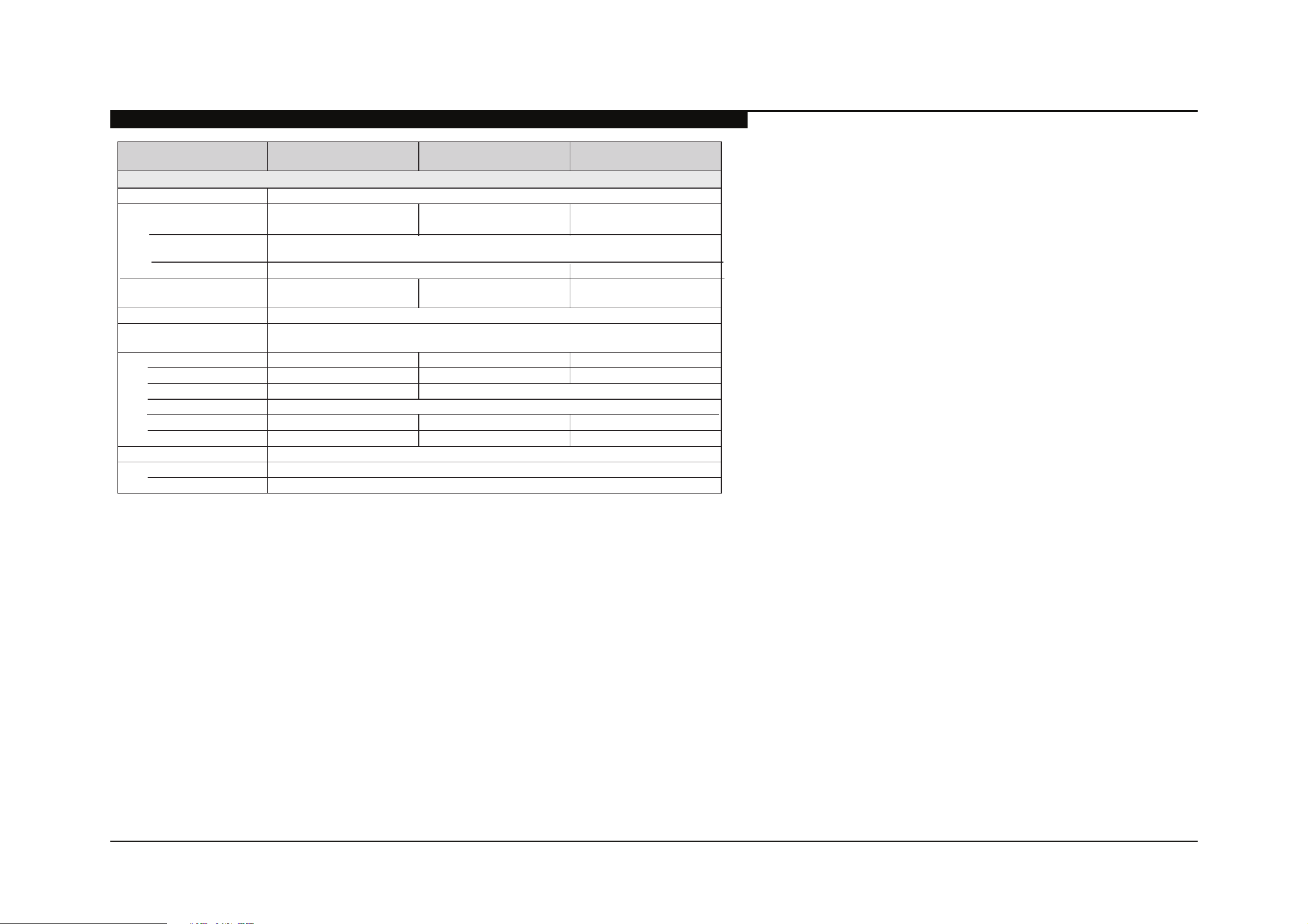
Power and others
Power requirement 110-220 V AC, 60 Hz
Power consumption
in use
in DAM*
Screen size
(inches measured diagonally)
Speaker
Full range with speaker box
Dimensions with stand
wall-mount hole pattern (mm)
wall-mount screw size (mm)
Supplied accessories
Optional accessories Connecting cables / Support Belt Kit/Wall-Mount Bracket
Wall-Mount Bracket*
1
bydnats ni
without stand
(You may hear a clicking noise during the download but this is normal.)
Less than 0.2 W Less than 0.23 W
(32 class)
(mm)
(2)
(mm) 764 × 507 × 250 952 × 613 × 250 1,085 × 688 × 260
(mm) 764 × 475 × 73 952 × 581 × 74 1,085 × 656 × 74
200 × 200
See “Checking the accessories”
2
15 W
34 × 160
M6
SU-WL500
300 × 300
)lacitrev( senil 080,1 × )latnoziroh( stod 029,1 noituloser yalpsiD
46EX605
W 12198 W 80 W
sehcni 64sehcni 0432 inches
4.819.411.11)gk( dnats htiwssaM
1.617.211.9)gk( dnats tuohtiw
*1 Download Acquisition Mode (DAM) is used for software updates.
8ptional accessories availability depends on its stock.
8esign and specifications are subject to change without notice.
KDL-32EX605/40EX605/46EX605 2
Page 8
WARNING!!
<*%($.4/,(.*%,&/*$0.&;#&%$".-46%1#%-$#6%6-&(*+%/*2%$#&'()#%,.%/'.(6%7.$$(14#%$".)9%"/=/&6:%1#)/-$#%.0%4('#%)"/$$($8%!"#%)"/$$($%.0%,"($%
&#)#('#&%($%6(&#),42%).**#),#6%,.%,"#%<>%7.?#&%4(*#8
! SAFETY-RELATED COMPONENT WARNING!!
>.;7.*#*,$%(6#*,(5#6%12%$"/6(*+%/*6%!%;/&9%.*%,"#%#@74.6#6%'(#?$%/&#%)&(,()/4%0.&%$/0#%.7#&/,(.*8%
A#74/)#%/44%).;7.*#*,$%?(,"%B.*2%7/&,$%?".$#%7/&,%*-;1#&$%/77#/&%/$%$".?*%(*%,"($%;/*-/4%.&%(*%$-774#;#*,$%7-14($"#6%12%B.*28%C,%($%
#$$#*,(/4%,"/,%/44%)&(,()/4%7/&,$%1#%J/)#6%.*42%?(,"%,"#%7/&,%*-;1#&%$7#)(5#6%(*%,"($%;/*-/4%,.%7&#'#*,%#4#),&()%$".)9:%5&#:%.&%.,"#&%"/=/&68
>(&)-(,%/6D-$,;#*,$%,"/,%/&#%)&(,()/4%0.&%$/0#%.7#&/,(.*%/&#%(6#*,(5#6%(*%,"($%;/*-/48%
E.44.?%,"#$#%7&.)#6-&#$%?"#*#'#&%)&(,()/4%).;7.*#*,$%/&#%J/)#6%.&%(;7&.7#&%.7#&/,(.*%($%$-$7#),#68%
FG!HI%J.%*.,%;.6(02%,"#%.&(+(*/4%6#$(+*%?(,".-,%.1,/(*(*+%?&(,,#*%7#&;($$(.*%0&.;%,"#%;/*-0/),-&#&%.&%2.-%?(44%'.(6%,"#%.&(+(*/4%7/&,$%/*6%
4/1.&%+-/&/*,##8
CUIDADOS E PRECAUÇÕES
CAUTION
!"#$#%$#&'()(*+%(*$,&-),(.*$%/&#%0.&%-$#%12%3-/4(5#6%$#&'()#%7#&$.**#4%.*428%!.%-)#%,"#%&($9%.0%#4#),&()%$".)9:%6.%*.,%7#&0.&;%/*2%$#&'()(*+%
.,"#&%,"/*%,"/,%).*,/(*#6%(*%,"#%.7#&/,(*+%(*$,&-),(.*$%-*4#$$%2.-%/&#%3-/4(5#6%,.%6.%$.8
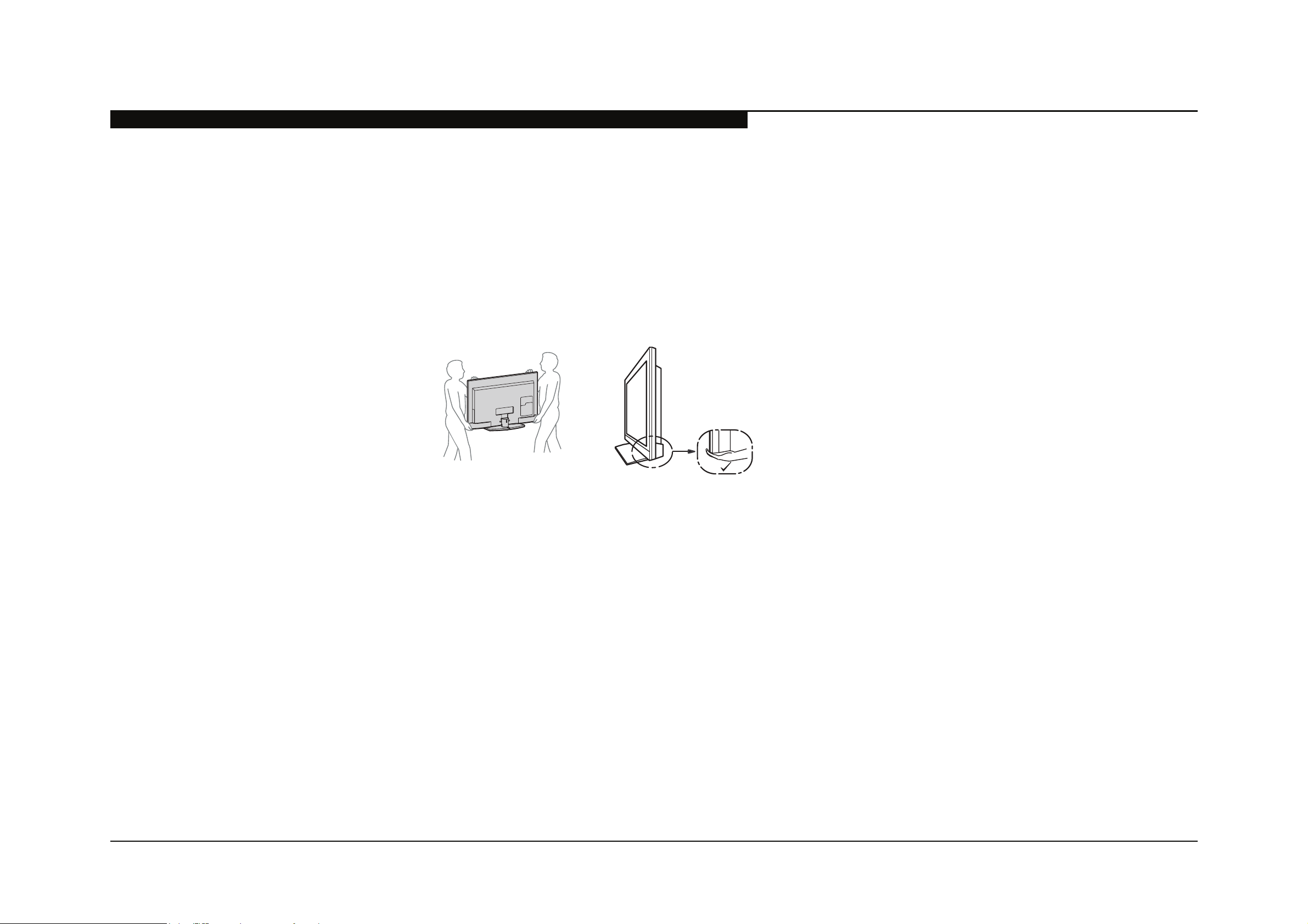
CARRYING THE TV
arry the TV with the adequate number of people; larger size TVs require two or more people.
orrect hand placement while car rying the TV is very importa nt for safety and to avoid
damage.
KDL-32EX605/40EX605/46EX605 3
Page 9
CUIDADO COM OS COMPONENTES DE SE
USE CAUTION WHEN HANDLING THE LCD PANEL
When repairing the LCD panel, be sure you are grounded by using a wrist band.
When installing the LCD panel on a wall, the LCD panel must be secured using the 4 mounting holes on the rear cover.
KL% J.%*.,%7&#$$%.*%,"#%7/*#4%.&%0&/;#%#6+#%,.%/'.(6%,"#%&($9%.0%#4#),&()%$".)98
ML% J.%*.,%$)&/,)"%.&%7&#$$%.*%,"#%7/*#4%?(,"%/*2%$"/&7%.1D#),$8
NL% J.%*.,%4#/'#%,"#%;.6-4#%(*%"(+"%,#;7#&/,-&#$%.&%(*%/&#/$%.0%"(+"%"-;(6(,2%0.&%/*%#@,#*6#6%7#&(.6%.0%,(;#8
OL% J.%*.,%#@7.$#%,"#%P>J%7/*#4%,.%6(&#),%$-*4(+",8
QL% <'.(6%).*,/),%?(,"%?/,#&8%C,%;/2%)/-$#%/%$".&,%)(&)-(,%?(,"(*%,"#%;.6-4#8
RL% J($).**#),%,"#%<>%7.?#&%?"#*%J/)(*+%,"#%1/)94(+",%.&%(*'#&,#&%)(&)-(,8%ST(+"%'.4,/+#%.))-&$%/,%,"#%(*'#&,#&%)(&)-(,%/,%RQUV&;$8L
GURANÇA
WL% <4?/2$%)4#/*%,"#%P>J%7/*#4%?(,"%/%$.0,%)4.,"%;/,#&(/48
XL% Y$#%)/&#%?"#*%"/*64(*+%,"#%?(&#$%.&%).**#),.&$%.0%,"#%(*'#&,#&%)(&)-(,8%J/;/+(*+%,"#%?(&#$%;/2%)/-$#%/%$".&,8
ZL% [&.,#),%,"#%7/*#4%0&.;%HBJ%,.%/'.(6%6/;/+(*+%,"#%#4#),&.*()%)(&)-(,%S>\]GBL8
KUL% J-&(*+%,"#%/(&:%JG%FG!%4#/'#%,"#%[.?#&%G*%0.&%;.&#%,"/*%K%".-&%?"(4#%,"#%!V%($%0/)#%6.?*%.*%/%)4.,"8
KDL-32EX605/40EX605/46EX605 4
Page 10
INSPEÇÃO DE SEGURANÇA
r
(0.75V)
E(+-&#%<8%Y$(*+%/*%<>%'.4,;#,#&%,.%)"#)9%<>%4#/9/+#8
<0,#&%).&&#),(*+%,"#%.&(+(*/4%$#&'()#%7&.14#;:%7#&0.&;%,"#%0.44.?(*+%$/0#,2%)"#)9$%1#0.&#%#/$(*+%,"#%$#,%,.%,"#%)-$,.;#&I
K8% >"#)9%,"#%/&#/%.0%2.-&%/(&%0.&%-*$.46#%.&%7..&42%$.46#%).**#),(.*$8%
>"#)9%,"#%#*,(&#%1./&6%$-&0/)#%0.&%$.46#&%$74/$"#$%/*6%1&(6+#$8
M8% >"#)9%,"#%(*,#&1./&6%?(&(*+%,.%#*$-&#%,"/,%*.%?(&#$%/&#%^7(*)"#6_%.&%,.-)"(*+%
"(+"\?/,,/+#%&#$($,.&$8
N8% >"#)9%,"/,%/44%).*,&.4%9*.1$:%$"(#46$:%).'#&$:%+&.-*6%$,&/7$:%/*6%;.-*,(*+%
"/&6?/&#%"/'#%1##*%J/)#68%`#%/1$.4-,#42%)#&,/(*%,"/,%2.-%"/'#%J/)#6%
/44%,"#%(*$-4/,.&$8
O8% P..9%0.&%-*/-,".&(=#6%J/)#;#*,%7/&,$:%7/&,()-4/&42%,&/*$($,.&$:%,"/,%?#&#%
(*$,/44#6% 6-&(*+% /% 7&#'(.-$% /(&8% [.(*,% ,"#;% .-,% ,.% ,"#% )-$,.;#&% /*6%
&#).;;#*6%,"#(&%J/)#;#*,8
0.15 µF
To Exposed Metal
Parts on Set
AC
Voltmete
Q8% P..9%0.&%7/&,$%?"()":%,".-+"%0-*),(.*(*+:%$".?%.1'(.-$%$(+*$%.0%6#,#&(.&/,(.*8%
[.(*,%,"#;%.-,%,.%,"#%)-$,.;#&%/*6%&#).;;#*6%,"#(&%J/)#;#*,8
R8% >"#)9%,"#%4(*#%).&6$%0.&%)&/)9$%/*6%/1&/$(.*8%A#).;;#*6%,"#%J/)#;#*,%
.0%/*2%$-)"%4(*#%).&6%,.%,"#%)-$,.;#&8
W8%% >"#)9% ,"#% /*,#**/%,#&;(*/4$:%;#,/4% ,&(;:% ^;#,/44(=#6_% 9*.1$:%$)&#?$:%/*6%
/44%.,"#&%#@7.$#6%;#,/4%7/&,$%0.&%<>%4#/9/+#8%>"#)9%4#/9/+#%/$%6#$)&(1#6%
1#4.?8
Earth Ground
KDL-32EX605/40EX605/46EX605 5
Page 11

LEAKAGE TEST
!"#%<>%4#/9/+#%0&.;%/*2%#@7.$#6%;#,/4%7/&,%,.%#/&,"%+&.-*6%/*6%0&.;%/44%
#@7.$#6%;#,/4%7/&,$%,.%/*2%#@7.$#6%;#,/4%7/&,%"/'(*+%/%&#,-&*%,.%)"/$$($:%;-$,%
*.,%#@)##6%U8Q%;<SQUU%;()&./;7#&#$L8%P#/9/+#%)-&&#*,%)/*%1#%;#/$-%12%
/*2%.*#%.0%,"&##%;#,".6$8
K8% <%).;;#&)(/4%4#/9/+#%,#$,#&:%$-)"%/$%,"#%B(;7$.*%MMZ%.&%A><%a!\QOU<8%
E.44.?%,"#%;/*-0/),-&#&$b%(*$,&-),(.*$%,.%-$#%,"#$#%(*$,&-),(.*$8
M8% <% 1/,,#&2\.7#&/,#6% <>% ;(44(/;7;#,#&8% !"#% J/,/% [&#)($(.*% MOQ% 6(+(,/4%
;-4,(;#,#&%($%$-(,/14#%0.&%,"($%D.18
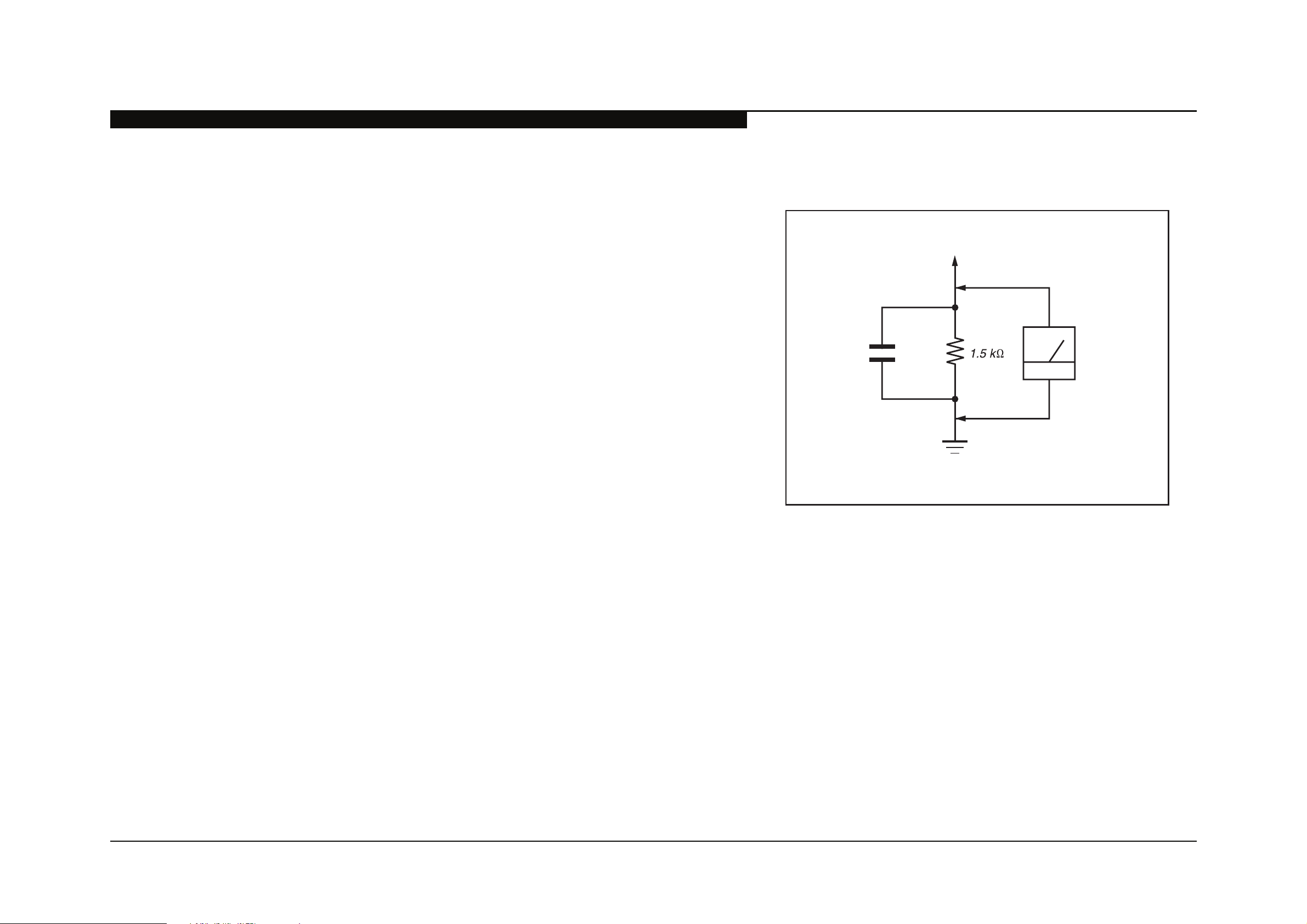
N8% ]#/$-&(*+%,"#%'.4,/+#%6&.7%/)&.$$%/%&#$($,.&%12%;#/*$%.0%/%VG]%.&%1/,,#&2\
.7#&/,#6%<>% '.4,;#,#&8%!"#% ^4(;(,_%(*6()/,(.*% ($% U8WQ%V:% $.% /*/4.+% ;#,#&$%
;-$,%"/'#%/*%/))-&/,#%4.?%'.4,/+#%$)/4#8
INSPEÇÃO DE SEGURANÇA
Trouble Light
Ohmmeter
AC Outlet Box
% !"#%B(;7$.*b$%MQU%/*6%B/*?/%BT\RN!AJ%/&#%#@/;74#$%.0%7/$$('#%VG]$%
,"/,%/&#%$-(,/14#8%F#/&42%/44%1/,,#&2\.7#&/,#6%6(+(,/4%;-4,(;#,#&$%,"/,%"/'#%/%
M%V<>%&/*+#%/&#%$-(,/14#%S$##%E(+-&#%<L8
HOW TO FIND A GOOD EARTH GROUND
<%).46\?/,#&%7(7#%($%/%+-/&/*,##6%#/&,"%+&.-*6c%,"#%).'#&\74/,#%&#,/(*(*+%$)&#?%
.*%;.$,%<>%.-,4#,%1.@#$%($%/4$.%/,%#/&,"%+&.-*68
C0%,"#%&#,/(*(*+%$)&#?%($%,.%1#%-$#6%/$%2.-&%#/&,"%+&.-*6:%'#&(02%,"/,%(,%($%/,%
+&.-*6%12%;#/$-&(*+%,"#%&#$($,/*)#%1#,?##*%(,%/*6%/%).46\?/,#&%7(7#%?(,"%/*%
.";;#,#&8%!"#%&#/6(*+%$".-46%1#%=#&.%.";$8
C0%/%).46\?/,#&%7(7#%($%*.,%/))#$$(14#:%).**#),%/%RU\,.%KUU\?/,,%,&.-14#\4(+",%S*.,%
/%*#.*%4/;7L%1#,?##*%,"#%".,%$(6#%.0%,"#%&#)#7,/)4#%/*6%,"#%&#,/(*(*+%$)&#?8%
!&2%1.,"%$4.,$:%(0%*#)#$$/&2:%,.%4.)/,#%,"#%".,%$(6#%.*%,"#%4(*#c%,"#%4/;7%$".-46%
4(+",%/,%*.&;/4%1&(44(/*)#%(0%,"#%$)&#?%($%/,%+&.-*6%7.,#*,(/4%S$##%E(+-&#%`L8
Cold-water Pipe
E(+-&#%`8%>"#)9(*+%0.&%#/&,"%+&.-*68
KDL-32EX605/40EX605/46EX605 6
Page 12

Self Diagnosis
Supported model
FUNÇÃO DE AUTO-DIAGNÓSTICO
SELF DIAGNOSIS FUNCTION
!"#%-*(,$%(*%,"($%;/*-/4%).*,/(*%/%$#40\6(/+*.$,()%0-*),(.*8%C0%/*%#&&.&%.))-&$:%,"#%B!<FJ`d%PHJ%?(44%/-,.;/,()/442%1#+(*%,.%e/$"8%!"#%*-;1#&%
.0%,(;#$%,"#%PHJ%e/$"#$%,&/*$4/,#$%,.%/%7&.1/14#%$.-&)#%.0%,"#%7&.14#;8%<%6#5*(,(.*%.0%,"#%B!<FJ`d%PHJ%e/$"%(*6()/,.&$%($%4($,#6%(*%,"#%
(*$,&-),(.*%;/*-/4%0.&%,"#%-$#&b$%9*.?4#6+#%/*6%�#&#*)#8%C0%/*%#&&.&%$2;7,.;%)/**.,%1#%&.6-)#6:%,"#%&#;.,#%).;;/*6#&%)/*%1#%-$#6%,.%
&#'(#?%,"#%0/(4-&#%.))-&&#*)#%6/,/%$,.%(*%;#;.&2%,.%&#'#/4%7/$,%7&.14#;$%/*6%".?%.0,#*%,"#$#%7&.14#;$%.))-&8
DIAGNOSTIC TEST INDICATORS
a"#*%/*%#&&.&%.))-&$:%,"#%B!<FJ`d%PHJ%?(44%e/$"%/%$#,%*-;1#&%.0%,(;#$%,.%(*6()/,#%,"#%7.$$(14#%)/-$#%.0%,"#%7&.14#;8%C0%,"#&#%($%;.&#%,"/*%
.*#%#&&.&:%,"#%PHJ%?(44%(6#*,(02%,"#%5&$,%.0%,"#%7&.14#;%/&#/$8%
A#$-4,%0.&%/44%.0%,"#%0.44.?(*+%6(/+*.$,()%(,#;$%/&#%6($74/2#6%.*%$)&##*8%
C0%,"#%$)&##*%6($74/2$%/%^U_:%*.%#&&.&%"/$%.))-&%8
;%'.*)+(%$/E(#@
RGB_SEN
MAIN_POWER Main Power Error 2
DC_ALERT
DTT_WDT
AUD_PROT
BALANCER
TCON ERR TCON Error
HFR ERROR HFR Error
P_ID_ERR Panel ID NVM Error
BACKLITE Backlight Error 6 BAL (Main) Board
TEMP_ERR Temperature Error BAL (Main) Board
FAN_ERR
;%'.*)+(%$/E(#@
;#+$-%"(%)*
RGB Sensor ACK Error
DC Alert
DTT Error
Audio Error Detection
Fan Error
(Not used in these models)
D2@A#-/)3/(%@#+/!('*0A4/
K=;/A7%*9+
NA NA
3
4Panel Balancer Error
5
7
GE3B (Power) Board (KDL-32EX605/40EX605 Only)
GE2C (Power) Board (KDL-46EX605 Only)
BAL (Main) Board
BAL (Main) Board
GE3B (Power) Board (KDL-32EX605/40EX605 Only)
GE2C (Power) Board (KDL-46EX605 Only)
BAL (Main) Board
LCD Panel
TCON Contol MT Board
BAL (Main) Board
NA
C)++%A7#/K)$'(%)*
KDL-32EX605/40EX605/46EX605 7
Page 13

STANDBY LED FLASH COUNT
Ambient Sensor/
(IR) Infrared Receiver
Picture Off /
Timer LED
Standby LED Power LED
2 times
5 times
LED ON 0.3 sec.
LED OFF 0.3 sec.
LED OFF
3 sec.
FUNÇÃO DE AUTO-DIAGNÓSTICO
KDL-32EX605/40EX605/46EX605 8
Page 14

VIEWING THE SELF CHECK DIAGNOSTIC LIST
Total operation time by hour (MAX:65535)
Boot count (MAX:65535)
Panel operation time by hour (MAX:65535)
Total operation time by hour (MAX:65535)
Boot count (MAX:65535)
Panel operation time by hour (MAX:65535)
0501210811 0412311234 0311111825 00
-------------- -------------- -------------- 00
-------------- -------------- -------------- 00
-------------- -------------- -------------- 00
-------------- -------------- -------------- 00
002 MAIN_POWE
003 DC_ALERT1
003 AUD_PROT
004 BALANCER
005 HFR_ERR
005 P_ID_ERR
12345-00333-0678912345-00333-06789- -
-------------- -------------- -------------- 00
003 DTT_WDT
-------------- -------------- -------------- 00
005 TCON_ERR
-------------- -------------- -------------- 00
-------------- -------------- -------------- 00
-------------- -------------- -------------- 00
006 BACKLITE
007 TEMP_ERR
010 RESERVED
-------------- -------------- -------------- 00
007 FAN_ERR
-------------- -------------- -------------- 00
-------------- -------------- -------------- 00
000 RGB_SEN
011 RESERVED
-------------- -------------- -------------- 00
SELF CHECK
StandBy LED Flash Count
Diagnostic Item
Error history (Most recent time the failure occurred)
Error history (Failure time before the last occurrence)
Error history (Failure time before the 2
nd
to last occurrence)
Error Count (00-99)
E.&%#&&.&$%?(,"%$2;7,.;$%$-)"%/$%^7.?#&%$.;#,(;#$%$"-,$%.00_%.&%^$)&##*%$.;#,(;#$%+.#$%.-,_%,"/,%)/**.,%1#%).*5&;#6:%(,%($%7.$$(14#%,.%
1&(*+%-7%7/$,%.))-&&#*)#$%.0%/%0/(4-&#%0.&%).*5&;/,(.*%.*%,"#%B#40%>"#)9%6(/+*.$,()%$)&##*I
K8% !V%;-$,%1#%(*%$,/*612%;.6#8%S[.?#&%.00L8
M8% [&#$$%,"#%0.44.?(*+%1-,,.*$%.*%,"#%A#;.,#%>.;;/*6#&%?(,"(*%/%$#).*6%.0%#/)"%.,"#&I%
FUNÇÃO DE AUTO-DIAGNÓSTICO
JCB[P<d
%>"/**#4%
5
%V.4-;#%
\
[GaHA
8
% f%FG!HI%!"($%6(00#&$%0&.;%/))#$$(*+%B#&'()#%<6D-$,;#*,$%].6#%SV.4-;#%gL
KDL-32EX605/40EX605/46EX605 9
Page 15

FUNÇÃO DE AUTO-DIAGNÓSTICO
CLEARING THE SELF CHECK DIAGNOSTIC LIST
B(*)#%,"#%6(/+*.$,()%&#$-4,$%6($74/2#6%.*%,"#%$)&##*%/&#%*.,%/-,.;/,()/442%)4#/:%/4?/2$%)"#)9%,"#%$#40\6(/+*.$,()%$)&##*%/0,#&%2.-%"/'#%
).;74#,#6%,"#%/(&$%,.%1#%$-&#%2.-%"/'#%)4#/%,"#%&#$-4,%6($74/2%,.%^U_8
K8% H&&.&%"($,.&2%/*6%H&&.&%).-*,%I[&#$$%,"#%>"/**#4%
M8% [/*#4%.7#&/,(.*%,(;#%I[&#$$%,"#%>"/**#4%
7
8
%>"/**#4%
%>"/**#4%
EXITING THE SELF CHECK DIAGNOSTIC SCREEN
K8% !.%#@(,%,"#%B#40%J(/+*.$,()%$)&##*:%,-&*%.00%,"#%7.?#&%,.%,"#%!V%12%7&#$$(*+%,"#%[GaHA%1-,,.*%.*%,"#%&#;.,#%.&%,"#%[GaHA%1-,,.*%.*%
,"#%!V8
U
%8
U
%8
KDL-32EX605/40EX605/46EX605 10
Page 16

KDL-32EX605/40EX605/46EX605 11
1)@")*#*(+/ *)(/ %0#*(%�/ A4/ '/ "'-(/ *2@A#-/ )-/
0#+$-%"(%)*/'-#/*)(/+()$9#0/A#$'2+#/(8#4/'-#/+#70)@/
-#L2%-#0/3)-/-)2(%*#/+#-G%$#?
M8#/$)@")*#*(/"'-(+/)3/'*/'++#@A74/'-#/%*0%$'(#0/A4/(8#/
-#3#-#*$#/*2@A#-+/%*/(8#/3'-/-%.8(/$)72@*/)3/(8#/"'-(+/7%+(/
'*0/N%(8%*/(8#/0)((#0/7%*#+/)3/(8#/0%'.-'@?
*
E(#@+/@'-9#0/N%(8/'*/'+(#-%+9/'-#/*)(/+()$9#0/+%*$#/
(8#4/ '-#/ +#70)@/-#L2%-#0/3)-/ -)2(%*#/ +#-G%$#?/ / =O"#$(/
+)@#/0#7'4/N8#*/)-0#-%*.//(8#+#/$)@")*#*(+?
D:M=P/ M8#/ $)@")*#*(+/%0#*(%�/A4/+8'0%*./
'*0/
!
/@'-9/'-#/$-%(%$'7/3)-/+'3#(4?/6#"7'$#/)*74/
N%(8/"'-(/*2@A#-/+"#$%�?/
D:M=P/M8#/$)@")*#*(+/ %0#*(%�/A4/ '/-#0/ )2(7%*#/'*0/'/
/@'-9/$)*('%*/
$)*&0#*(%'7/%*3)-@'(%)*?/!"#$%&$/%*+(-2$(%)*+/@2+(/A#/'08#-#0/()/N8#*#G#-/
(8#+#/$)@")*#*(+/'-#/-#"'%-#0/'*0B)-/-#"7'$#0?/
!##/H""#*0%O/HP/=*$-4"(%)*/Q#4/1)@")*#*(+/%*/(8#/A'$9/)3/(8%+/@'*2'7?/
SEC 1. INFORMAÇÃO DE DESMONTAGEM E CÓDIGOS DE PEÇ
AS
1-1. REMOÇÃO DO PEDESTAL MONTADO
A
Remove 4 screws from Table-Top Stand Assembly
B
Lift up TV set to detach from Table-Top Stand Assembly
C
Gently place the TV set face down onto a soft cloth
/ 6=<?/D:?// CH6M/D:?/ ;=!16ECME:D/ VH!!=SRKT/ED1KW;=!X / 6=<?/D:?// CH6M/D:?/ ;=!16ECME:D/ VH!!=SRKT/ED1KW;=!X
1 A-1780-315-A PEDESTAL MONTADO (L3C) [2-5]
(KDL-46EX605 ONLY)
2 A-1768-634-A
BASE MONTADO (M3A)
(KDL-32EX605/40EX605 ONLY)
3 4-
193-169-01 TAMPA DO PEDESTAL (M3A FRONTAL)
4 4-1
89-302-01 TAMPA PLASTICA (M3A TRASEIRA)
5 4-170-449-01
SUPORTE DO PEDESTAL (M3A)
(KDL-32EX605 ONLY)
5 4-170-450-01
SUPORTE DO PEDESTAL (ML3A)
(KDL-40EX605/46EX605 ONLY)
6 2-580-608-01 SCREW, +PSW M5X16
(SCREWS TO ATTACH TABLE-TOP STAND TO LCD TV)
For product protection and safety reasons, Sony strongly recommends
that you use the screws provided with the TV
CAUTION: These screws cannot be used to secure the TV to
the Wall Mount Brackets
2-580-608-01 SCREW, +PSW M5X16
2
1
5
3
4
6
B
A
Soft Cloth
C
Page 17

53
55
54
56
51
52
A
H
G
F
I
B
C
D
E
1-2. REMOÇÃO DA TAMPA TRASEIRA, TAMPA INFERIOR, SUPORTE VESA E UNIDADE CHAVE
A
Remove 4 screws from Rear Cover to detach from Bezel
B
Remove 8 screws from Rear Cover to detach from Panel
8 from KDL-32EX605/40EX605 Only
10 from KDL-46EX605 Only
C
Remove 1 screw from Rear Cover to detach from Terminal area
D
Remove 1 screw from Rear Cover to detach from Side Jack area
E
Lift up Rear Cover from bottom side to detach from Bezel
F
Disconnect AC Inlet from GE3B/GE2C (Power) Boards and detach from Under Cover
G
Remove 1 screw from Under Cover to detach from Bottom Frame
H
Slide out Vesa Brackets to detach from Rear Cover
I
Lift up Switch Unit and disconnect 1 connector to remove from Panel
NOTE: The Vesa Brackets are not included with the Rear Cover and must be
reattached to the replacement Rear Cover
Ver. 1.1
INFORMAÇÃO DE DESMONTAGEM E CÓDIGOS DE PEÇAS
D:M=P/ M8#/ $)@")*#*(+/%0#*(%�/A4/+8'0%*./
!
'*0/
/@'-9/'-#/$-%(%$'7/3)-/+'3#(4?/6#"7'$#/)*74/
N%(8/"'-(/*2@A#-/+"#$%�?/
D:M=P/M8#/$)@")*#*(+/ %0#*(%�/A4/ '/-#0/ )2(7%*#/'*0/'/
$)*&0#*(%'7/%*3)-@'(%)*?/!"#$%&$/%*+(-2$(%)*+/@2+(/A#/'08#-#0/()/N8#*#G#-/
(8#+#/$)@")*#*(+/'-#/-#"'%-#0/'*0B)-/-#"7'$#0?/
!##/H""#*0%O/HP/=*$-4"(%)*/Q#4/1)@")*#*(+/%*/(8#/A'$9/)3/(8%+/@'*2'7?/
/@'-9/$)*('%*/
/ 6=<?/D:?// CH6M/D:?/ ;=!16ECME:D/ VH!!=SRKT/ED1KW;=!X / 6=<?/D:?// CH6M/D:?/ ;=!16ECME:D/ VH!!=SRKT/ED1KW;=!X
51 4-176-751-01 TAMPA TRASEIRA (32)
(KDL-32EX605 ONLY)
51 4-176-752-01
(KDL-40EX605 ONLY)
51 4-176-753-02
(KDL-46EX605 ONLY)
52 3-196-465-12
53 4-168-272-01
! 54 1-842-031-11 AC INLET (2P)
TAMPA TRASEIRA (40)
TAMPA TRASEIRA(46)
TAMPA, ECS
SUPORTE, VESA (S)
55 4-176-838-01
(KDL-32EX605 ONLY)
55 4-184-861-01
(KDL-40EX605/46EX605 ONLY)
56
Y-8287-064-A PLACA HSW (CHAVE) MONTADA
2-580-640-01 SCREW, +BVTP 4X16 TYPE2 IT-3
7-685-648-79 SCREW, +BVTP 3X12 TYPE2 IT-3
4-159-298-01 SCREW, +PSW M4X10
TAMPA INFERIOE (32)
TAMPA INFERIOR (40)
KDL-32EX605/40EX605/46EX605 12
Page 18

INFORMAÇÃO DE DESMONTAGEM E CÓDIGOS DE PEÇAS
A
B
D
E
C
104
102
102
101
103
1-3 REMOÇÃO DOS ALTO-FALANTES, SUPORTES DOS ALTO-FALANTES E A PLACA HLR
A
Remove screws from Speaker Bracket Right to detach from Bezel
1 from KDL-32EX605 Only
2 from KDL-40EX605/46EX605 Only
B
Remove screws from Speaker to detach from Speaker Bracket Right
4 from KDL-32EX605 Only
2 from KDL-40EX605/46EX605 Only
C
Remove screws from Speaker Bracket Left to detach from Bezel
1 from KDL-32EX605 Only
2 from KDL-40EX605/46EX605 Only
D
Remove screws from Speaker to detach from Speaker Bracket Left
4 from KDL-32EX605 Only
2 from KDL-40EX605/46EX605 Only
E
Disconnect 1 connector from HLR Board, then release clips and lift up to remove from LED Guide
D:M=P/ M8#/ $)@")*#*(+/%0#*(%�/A4/+8'0%*./
!
'*0/
/@'-9/'-#/$-%(%$'7/3)-/+'3#(4?/6#"7'$#/)*74/
N%(8/"'-(/*2@A#-/+"#$%�?/
D:M=P/M8#/$)@")*#*(+/ %0#*(%�/A4/ '/-#0/ )2(7%*#/'*0/'/
$)*&0#*(%'7/%*3)-@'(%)*?/!"#$%&$/%*+(-2$(%)*+/@2+(/A#/'08#-#0/()/N8#*#G#-/
(8#+#/$)@")*#*(+/'-#/-#"'%-#0/'*0B)-/-#"7'$#0?/
!##/H""#*0%O/HP/=*$-4"(%)*/Q#4/1)@")*#*(+/%*/(8#/A'$9/)3/(8%+/@'*2'7?/
/@'-9/$)*('%*/
/ 6=<?/D:?// CH6M/D:?/ ;=!16ECME:D/ VH!!=SRKT/ED1KW;=!X / 6=<?/D:?// CH6M/D:?/ ;=!16ECME:D/ VH!!=SRKT/ED1KW;=!X
101 Y-8287-185-A PLACA HLR MONTADA
102 1-826-873-41
103 4-176-757-01
(KDL-32EX605 ONLY)
103 4-184-862-01
(KDL-40EX605 ONLY)
103 4-184-864-01
(KDL-46EX605 ONLY)
ALTO-FALANTE (3.4X17.5CM)
SUPORTE DO ALTO-FALANTE ESQ. (32)
SUPORTE DO ALTO-FALANTE ESQ. (40)
SUPORTE DO ALTO-FALANTE ESQ. (46)
104 4-176-758-01 SUPORTE DO ALTO-FALANTE DIR. (32)
(KDL-32EX605 ONLY)
104 4-184-863-01
(KDL-40EX605 ONLY)
104 4-184-865-01
(KDL-46EX605 ONLY)
2-580-640-01 SCREW, +BVTP 4X16 TYPE2 IT-3
SUPORTE DO ALTO-FALANTE DIR. (40)
SUPORTE DO ALTO-FALANTE DIR. (46)
KDL-32EX605/40EX605/46EX605 13
Page 19

INFORMAÇÃO DE DESMONTAGEM E CÓDIGOS DE PEÇAS
155
154
153
152
151
B
C
F
G
H
E
D
A
1-4. REMOÇÃO DAS PLACAS GE3B/GE2C(FONTE), PLACA BAL E GABONETE FRONTAL
A
Lift-up Panel Brackets to detach from Bezel
4 from KDL-32EX605/40EX605 Only
6 from KDL-46EX605 Only
B
Remove 4 screws from GE3B/GE2C (Power) Boards
C
Disconnect 3 connectors from GE3B/GE2C (Power) Boards
D
Remove screws from Bottom Frame to detach from Panel
3 from KDL-32EX605 Only
5 from KDL-40EX605/46EX605 Only
E
Remove 4 screws from BAL Board
F
Disconnect 5 connectors from BAL Board
G
Slide Side Jack Bracket to right-side to remove from BAL Board
H
Carefully Lift up Panel to remove from Bezel
D:M=P/ M8#/ $)@")*#*(+/%0#*(%�/A4/+8'0%*./
!
'*0/
/@'-9/'-#/$-%(%$'7/3)-/+'3#(4?/6#"7'$#/)*74/
N%(8/"'-(/*2@A#-/+"#$%�?/
D:M=P/M8#/$)@")*#*(+/ %0#*(%�/A4/ '/-#0/ )2(7%*#/'*0/'/
$)*&0#*(%'7/%*3)-@'(%)*?/!"#$%&$/%*+(-2$(%)*+/@2+(/A#/'08#-#0/()/N8#*#G#-/
(8#+#/$)@")*#*(+/'-#/-#"'%-#0/'*0B)-/-#"7'$#0?/
!##/H""#*0%O/HP/=*$-4"(%)*/Q#4/1)@")*#*(+/%*/(8#/A'$9/)3/(8%+/@'*2'7?/
/@'-9/$)*('%*/
/ 6=<?/D:?// CH6M/D:?/ ;=!16ECME:D/ VH!!=SRKT/ED1KW;=!X / 6=<?/D:?// CH6M/D:?/ ;=!16ECME:D/ VH!!=SRKT/ED1KW;=!X
151 X-2548-060-3 GABINETE FRONTAL (32)
(KDL-32EX605 ONLY)
151 X-2548-061 (KDL-40EX605 ONLY)
151 X-2548-062-3
(KDL-46EX605 ONLY)
152 NA
153 4-166-286-21
AS INFORMAÇÕES DOS CÓDIGOS DAS PEÇAS DOS TODOS
PAINEIS DE LCD, CONSULTE MANUAL DO PAINEL DE LCD
3 GABINETE FRONTAL (40)
GABINETE FRONTAL (46)
PAINEL DE LCD
SUPORTE LATERAL JACK
154
NOTE: For BAL Board replacement, please refer to section
2-2. Adjustments After Replacing the BAL Board or the LCD Panel.
NOTE: Final software is not installed on this BAL Board. Install the update
after replacing this board using the instructions provided with the software.
155 1-474-218-11
(KDL-32EX605/40EX605 ONLY)
155 1-474-219-11
(KDL-46EX605 ONLY)
Y-8287-241-A PLACA BAL MONTADA
PLACA GE3B (FONTE) MONTADA
PLACA GE2C (FONTE) MONTADA
2-580-592-01 SCREW, +PSW M3X8
KDL-32EX605/40EX605/46EX605 14
Page 20

KDL-32EX605/40EX605/46EX605 15
INFORMAÇÃO DE DESMONTAGEM E CÓDIGOS DE PEÇAS
D:M=P/ M8#/ $)@")*#*(+/%0#*(%�/A4/+8'0%*./
'*0/
!
/@'-9/'-#/$-%(%$'7/3)-/+'3#(4?/6#"7'$#/)*74/
N%(8/"'-(/*2@A#-/+"#$%�?/
D:M=P/M8#/$)@")*#*(+/ %0#*(%�/A4/ '/-#0/ )2(7%*#/'*0/'/
/@'-9/$)*('%*/
$)*&0#*(%'7/%*3)-@'(%)*?/!"#$%&$/%*+(-2$(%)*+/@2+(/A#/'08#-#0/()/N8#*#G#-/
(8#+#/$)@")*#*(+/'-#/-#"'%-#0/'*0B)-/-#"7'$#0?/
!##/H""#*0%O/HP/=*$-4"(%)*/Q#4/1)@")*#*(+/%*/(8#/A'$9/)3/(8%+/@'*2'7?/
/ 6=<?/D:?// CH6M/D:?/ ;=!16ECME:D/ VH!!=SRKT/ED1KW;=!X / 6=<?/D:?// CH6M/D:?/ ;=!16ECME:D/ VH!!=SRKT/ED1KW;=!X
* 201 1-910-100-54 CONNECTOR ASSEMBLY 15P (32)
(KDL-32EX605 ONLY)
* 201 1-910-100-56 CONNECTOR ASSEMBLY 15P (40)
(KDL-40EX605 ONLY)
* 201 1-910-100-58 CONNECTOR ASSEMBLY 15P (46)
(KDL-46EX605 ONLY)
* 202 1-837-816-11 (LVDS) FLEXIBLE FLAT CABLE
(KDL-32EX605 ONLY)
* 202 1-837-817-11 (LVDS) FLEXIBLE FLAT CABLE
(KDL-40EX605 ONLY)
* 202 1-837-818-11 (LVDS) FLEXIBLE FLAT CABLE
(KDL-46EX605 ONLY)
* 203 1-910-100-53 HARNESS ASSEMBLY (32)
(KDL-32EX605 ONLY)
* 203 1-910-100-55 HARNESS ASSEMBLY (40)
(KDL-40EX605 ONLY)
* 203 1-910-100-57 HARNESS ASSEMBLY (46)
(KDL-46EX605 ONLY)
TCON
SPSP
HLR
SWITCH UNIT
GE3B/GE2C
CN6150
CN6001
CN6800
CN6801
CN2600
CN2602
CN4300
CN2561
CN3800
BAL
201
202
203
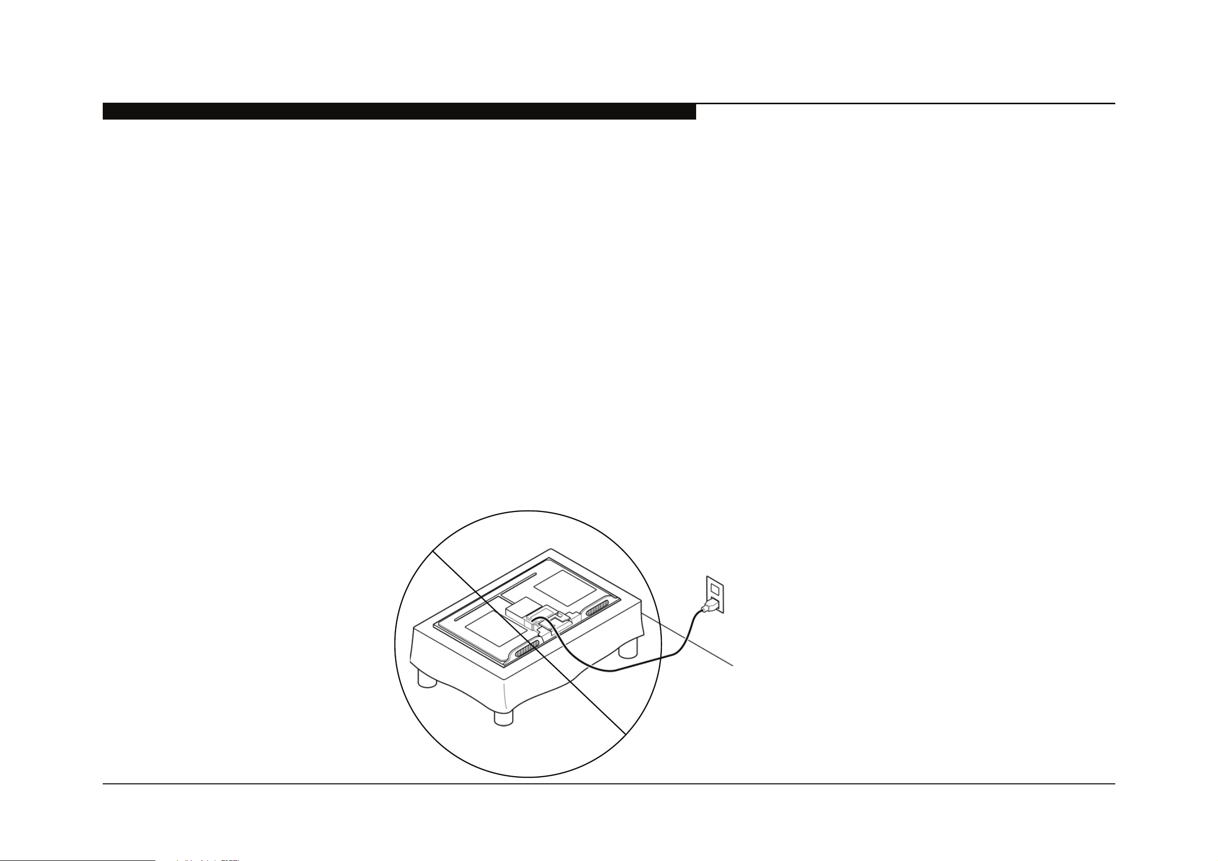
1-5. LIMPANDO PAINEL DE LCD
CAUTION: When cleaning the TV be sure to unplug the power cord to avoid any chance of electric shock.
Clean the cabinet of the TV with a dry soft cloth.
Wipe the LCD screen gently with a soft cloth.
!" #$%&&'()"*$+,)*"-+."&/"(/-'0/1"2,$3"+"45'$3"*5,63$5."-',*$/)/1"2,$3"+"*'5%$,')"'7"-,51"*'+8"+)1"2+(-"2+$/(9
!" :7"%*,)6"+"43/-,4+55."8(/$(/+$/1"45'$3;"85/+*/"7'55'2"$3/",)*$(%4$,')"8('0,1/1"')"$3/"8+4<+6/9
!" =/0/("%*/"*$(')6"*'50/)$*"*%43"+*"+"$3,))/(;"+54'3'5"'("&/)>,)/"7'("45/+),)69
!" ?/(,'1,4"0+4%%-,)6"'7"$3/"0/)$,5+$,')"'8/),)6*",*"(/4'--/)1/1"$'"/)*%(/"$'"8('8/("0/)$,5+$,')9
1-6. LEGENDA DOS PARAFUSOS
CBD ;=!16ECME:D 6=SH6Q! TOTAL
Š
2-580-640-01 SCREW, +BVTP 4X16 TYPE2 IT-3 RC(4), SPKR BRKT-L(1), SPKR BRKT-R(1), SPKR-L(4), SPKR-R(4) 14
Ť
7-685-648-79 SCREW, +BVTP 3X12 TYPE2 IT-3 RC to SIDE JACK(1), RC to TRMNL AREA(1) 2
ť
2-580-608-01 SCREW, +PSW M5X16 TABLE-TOP STAND(4), NECK to BASE(4) 8
Ū
2-580-592-01 SCREW, +PSW M3X8 GE3B(4), BAL(4) 8
Ũ
4-159-298-01 SCREW, +PSW M4X10 RC(8), UC(1), BTM FRM(3) 12
CBD ;=!16ECME:D 6=SH6Q! TOTAL
Š
2-580-640-01 SCREW, +BVTP 4X16 TYPE2 IT-3 RC(4), SPKR BRKT-L(2), SPKR BRKT-R(2), SPKR-L(2), SPKR-R(2) 12
Ť
7-685-648-79 SCREW, +BVTP 3X12 TYPE2 IT-3 RC to SIDE JACK(1), RC to TRMNL AREA(1) 2
ť
2-580-608-01 SCREW, +PSW M5X16 TABLE-TOP STAND(4), NECK to BASE(4) 8
Ū
2-580-592-01 SCREW, +PSW M3X8 GE3B(4), BAL(4) 8
Ũ
4-159-298-01 SCREW, +PSW M4X10 RC(8), UC(1), BTM FRM(5) 14
CBD ;=!16ECME:D 6=SH6Q! TOTAL
Š
2-580-640-01 SCREW, +BVTP 4X16 TYPE2 IT-3 RC(4), SPKR BRKT-L(2), SPKR BRKT-R(2), SPKR-L(2), SPKR-R(2) 12
Ť
7-685-648-79 SCREW, +BVTP 3X12 TYPE2 IT-3 RC to SIDE JACK(1), RC to TRMNL AREA(1) 2
ť
2-580-608-01 SCREW, +PSW M5X16 TABLE-TOP STAND(4) 4
Ū
2-580-592-01 SCREW, +PSW M3X8 GE2C(4), BAL(4) 8
Ũ
4-159-298-01 SCREW, +PSW M4X10 RC(10), UC(1), BTM FRM(5) 16
Q;K5JF=a`b_
Q;K5[b=a`b_
Q;K5[`=a`b_
>5c?/ 1:DD=1M:6!
Page 21

KDL-32EX605/40EX605/46EX605 16
INFORMAÇÃO DE DESMONTAGEM E CÓDIGOS DE PEÇAS
>5d?/ ACESSÓRIOS E EMBALAGEN
A-1768-620-A BAG ASSEMBLY,SCREW A
(KDL-32EX605/40EX605 ONLY)
A-1768-621-A BAG ASSEMBLY,SCREW C
(KDL-46EX605 ONLY)
4-180-192-13
MANUAL DE INSTRUÇÕES
* 4-180-045-11 SUPPLEMENT(STAND INSTALLATION)
>5e?/ DIVERSOS
4-182-211-01 GASKET
(KDL-32EX605/40EX605 ONLY)
! 1-837-645-12
CABO DE FORÇA
4-100-136-01 SHEET (CORE), C
(KDL-32EX605/40EX605 ONLY)
X-2348-140-3 SUPPORT BELT KIT
7-632-452-24 TAPE (NO.303) 18MMX35M YEL
>5>b?/ CONTROLE REMOTO
1-487-702-22 CONTROLE REMOTO (RM-YD047)
Page 22

SEC 2. AJUSTES DE SERVIÇO
DIGITAL SERVICE
001 OP
000 VERS ---
<MAIN> <SUB>
DM1.301J00AA SM1.010W00AA
M2.105C SB1.000W00AA
DD1.016J00AA SD1.010W00AA
(DM1.3 01J00AA) RF01.05
WP00.521J00AA ID1C117081
ID1C117081 LTY320AB01
PID04020000
WF:2.0.0.99 <BEM>
WF:0B BM1.012W00LU
Camera FW BB1.000W00LU
Camera FW BD1.011J46LUX
---.---------
SAMPLE SERVICE MENU
F5>?/ H11=!!ED\/!=6UE1=/H;fW!MS=DM/S:;=
1. TV must be in standby mode. (Power off).
2. Press the following buttons on the Remote Commander
within a second of each other:
DISPLAY
.
Channel
5
Volume
DISPLAY
+
POWER
Onscreen cursor
and select button
POWER
.
5
VOLUME+
6S5T;b[c
KDL-32EX605/40EX605/46EX605 17
Page 23

AJUSTES DE SERVIÇO
DIGITAL SERVICE
001 OP
000 VERS ---
<MAIN> <SUB>
DM1.301J00AA SM1.010W00AA
M2.105C SB1.000W00AA
DD1.016J00AA SD1.010W00AA
(DM1.3 01J00AA) RF01.05
WP00.521J00AA ID1C117081
ID1C117081 LTY320AB01
PID04020000
WF:2.0.0.99 <BEM>
WF:0B BM1.012W00LU
Camera FW BB1.000W00LU
Camera FW BD1.011J46LUX
---.---------
Sample Digital Service Menu
press
or
JUMP
OPTIONS
CHASSIS
000 CXD2813R
000 H_DET_NOSIG_CNT 1
Within each Service Menu are Categories and data information.
CHASSIS SERVICE
000 CXD2813R
000 H_DET_NOSIG_CNT 1
Item number
Category number
Item name
Category name
Data
Sample Chassis Service Menu
F5>5>?/ UE=,ED\/MZ=/!=6UE1=/S=DW!
Use the Remote Commander to view the Digital, 18'++%+ and !2A
Service Menus and their options.
3. To display the !#-G%$#/S#*2 that contains the Category you
want to adjust, press
fWSC
Commander.
or
:CME:D!
on the Remote
KDL-32EX605/40EX605/46EX605 18
Page 24

AJUSTES DE SERVIÇO
F5>5F?/ W!ED\/MZ=/6=S:M=/1:SSHD;=6/M:/UE=,/:6/
1ZHD\=/!=6UE1=/;HMH
Use the buttons on the Remote Commander to access the Service
Menu items and adjust the Data Values.
DISPLAY
4. To change the Category,
press
press
D)(#: Pressing
the Service Menu displayed.
5. To change the '0I2+(@#*(/%(#@,
press
4
to go back to the Previous Item.
6. To change the ;'('/U'72#,
press
6
to decrease the Data Value.
7. Press
8. To exit service mode, press
2
to move to the Next Category or
5
to go back to the Previous Category.
1
to move to the Next Item or
3
to increase the Data Value or
SWMED\
Channel
2
or
then press
5
5
Only changes the Categories within
Volume
0
to Write the changes.
Z:S=
or turn the TV power off.
+
POWER
F5F?/ H;fW!MS=DM!/H<M=6/6=CKH1ED\/MZ=/RHK/R:H6;/
:6/K1;/CHD=K
M8#/3)77)N%*./"-)$#02-#+/@2+(/A#/$)@"7#(#0/'3(#-/-#"7'$%*./(8#/RHK/
R)'-0/)-/(8#/K1;/"'*#7?//
! Update the TV to the latest software version
! Select the Model
! Select the Destination
! Verify model and panel information are correct
! Reconnect all cables
F5F5>?/ WC;HMED\/MZ=/!:<M,H6=
H3(#-/-#"7'$%*./(8#/RHK/R)'-0/)-/(8#/K1;/C'*#7Y/4)2/@2+(/2"0'(#/(8#/
+)3(N'-#/()/(8#/7'(#+(/G#-+%)*?//
R#3)-#/4)2/A#.%*
! Disconnect all cables (RF, External input, Ethernet, etc.) from
the TV
E*+(-2$(%)*+/3)-/2"0'(%*./(8#/+)3(N'-#/'-#/%*$720#0/N%(8/(8#/+)3(N'-#/
"'$9'.#?//H3(#-/$)@"7#(%*./(8#/+)3(N'-#/2"0'(#Y/"-)$##0/()/!#7#$(%*./(8#/
S)0#7?
KDL-32EX605/40EX605/46EX605 19
Page 25

F5F5F?/ !=K=1MED\/MZ=/S:;=K
DIGITAL SERVICE
001 OP
000 VERS ---
<MAIN> <SUB>
DM1.301J00AA SM1.010W00AA
M2.105C SB1.000W00AA
DD1.016J00AA SD1.010W00AA
(DM1.3 01J00AA) RF01.05
WP00.521J00AA ID1C117081
ID1C117081 LTY320AB01
PID04020000
WF:2.0.0.99 <BEM>
WF:0B BM1.012W00LU
Camera FW BB1.000W00LU
Camera FW BD1.011J46LUX
---.---------
4. Press
2
to move to the/bbF/S:;=K (Next) category.
DIGITAL SERVICE
002 MODEL
000 SEG 11: 3a-0.5
5. Using the table, press
3
to increase the data value or
6
to decrease the data value, to match the model of the TV.
Chassis Model Name
䎧
䏄
䏗
䏄
䎃
䎹
䏄
䏏
䏘
䏈
䎦
䏒
䏇
䏈
䎃
䎱
䏄
䏐
䏈
A
Z1-
L
KDL-32EX605 11 3a-0.5
A
Z1-
L
KDL-40EX605 11 3a-0.5
A
Z1-
L
KDL-46EX605 11 3a-0.5
DIGITAL SERVICE
002 MODEL
000 SEG 11: 3a-0.5
Data Value
Code Name
6. Proceed to Selecting the Destination.
AJUSTES DE SERVIÇO
H3(#-/-#"7'$%*./(8#/RHK/R)'-0/)-/K1;/C'*#7Y/.)/%*()/!#-G%$#/S)0#/()/+#(/
(8#/S)0#7/0'('/G'72#?/
1. TV must be in standby mode. (Power off).
2. Access Service Mode.
Press the following buttons on the Remote Commander
within a second of each other:
DISPLAY
3. Display the ;E\EMHK/!#-G%$#/S#*2.
NOTE: There are 3 Service Menus for this model, DIGITAL,
CHASSIS, and SUB. If the DIGITAL Service Menu is
not displayed, press
Commander.
Channel
5
fWSC
Volume
or
:CME:D!
+
on the Remote
POWER
KDL-32EX605/40EX605/46EX605 20
Page 26

AJUSTES DE SERVIÇO
DIGITAL SERVICE
002 MODEL
000 SEG 11: 3a-0.5
7. Press
1
to move to 001 DEST sub Category.
DIGITAL
SERVICE
002 MODEL
001 DEST
13: BR (BR grp)
Data Value
Destination
8. Using the table, press
3
to increase the data value or
6
to decrease the data value, to select the destination of the
TV.
GROUP
DESTINATION
CODE
DATA
VALUE
DESTINATION
BR 13 BRAZIL
AR 20 ARGENTINA
BR grp
CAUTION: Verify the DESTINATION is set correctly before
proceeding to the next step. If another destination Data
Value is selected, it may possibly corrupt the software which
would require a BAL Board replacement.
F5F5J?/ !=MMED\/MZ=/;=!MEDHME:D
H3(#-/-#"7'$%*./(8#/RHK/R)'-0/)-/(8#/K1;/C'*#7Y/(8#/0#+(%*'(%)*/7)$'(%)*/
@2+(/A#/+#(?//
1HWME:DP/!#7#$(%*./(8#/%*$)--#$(/0#+(%*'(%)*/@'4/-#L2%-%*./-#"7'$%*./(8#/
RHK/R)'-0?
KDL-32EX605/40EX605/46EX605 21
Page 27

AJUSTES DE SERVIÇO
2-2-4. VERIFYING THE MODEL AND PANEL INFORMATION
After saving the changes to the service data, verify the information.
1. TV must be in standby mode. (Power off).
2. Access Service Mode.
Press the following buttons on the Remote Commander
within a second of each other:
DISPLAY
Channel
3. Display the DIGITAL Service Menu.
NOTE: There are 3 Service Menus for this model, DIGITAL,
CHASSIS, and SUB. If the DIGITAL Service Menu is
not displayed, press
Commander.
DIGITAL SERVICE
5
JUMP
Volume
or
OPTIONS
+
POWER
on the Remote
Model Name Model ID Product ID Panel ID
KDL-32EX605 259736A3 345A0000 LTY(Z)320HM02 3a-0.5
KDL-32EX605 259736A3 345A0000 LTY(Z)320HM02 3a-0.5
KDL-40EX605 259736A4 345A0000 LTY(Z)400HM02 3a-0.5
KDL-40EX605 259736A4 345A0000 LTY(Z)400HM02 3a-0.5
KDL-46EX605 259736A5 345A0000 LTY(Z)460HM02 3a-0.5
KDL-46EX605 259736A5 345A0000 LTY(Z)460HM02 3a-0.5
5. Exit Service Mode by pressing
HOME
or turn the TV power
Code
Name
off.
6. Proceed to Reconnecting All Cables.
2-2-5. RECONNECTING ALL CABLES
After completing the changes to service mode, reconnect all the cables
(RF, External input, Ethernet, etc.) to the TV then verify the TV set picture.
If necessary, proceed to White Balance Adjustments.
Model ID
Product ID
4. Using the table, verify the Model ID and the Product ID
001 OP
000 VERS ---
<MAIN> <SUB>
DM1.301J00AA SM1.010W00AA
M2.105C SB1.000W00AA
DD1.016J00AA SD1.010W00AA
(DM1.3 01J00AA) RF01.05
WP00.521J00AA ID1C117081
ID259736A3
PID345A0000
WF:2.0.0.99 <BEM>
WF:0B BM1.012W00LU
Camera FW BB1.000W00LU
Camera FW BD1.011J46LUX
LTY(Z)320HM02
---.---------
match the information in the Service Menu.
Panel
Code
KDL-32EX605/40EX605/46EX605 22
Page 28

AJUSTES DE SERVIÇO
DIGITAL SERVICE
006 WB
000 WHITE_BALANCE ___
4. Press
0
to enter White Balance Adjustment mode.
5. To select the White Balance Adjustment setting that needs to
be changed, do the following:
a. To select R_DRV, press
1
.
b. To select G_DRV, press
2
.
c. To select B_DRV, press
3
.
d. To select R_BKG, press
4
.
e To select G_BKG, press
5
.
f. To select B_BKG, press
6
.
6. After selecting the White Balance setting, press
=DM
to
display the edit screen.
The screen displays a Please input WB items message.
DIGITAL SERVICE
WB
*1 R_DRV 128
2 G_DRV 128
3 B_DRV 128
4 R_BKG 128
5 G_BKG 128
6 B_BKG 128
Please input WB items
(0 - 255)
---
Gain
0: x 0.5, 128: x 1, 255: x1.5
Offset
128: offset 0
7. Using the numbers buttons on the remote, enter the Data
Value for the White Balance setting
(value must be between 1 and 255).
8. Press
=DM
to WRITE (save) the changes.
9. To exit White Balance Adjustment, press
fWSC
or
:CME:D!
F5J?/ ,ZEM=/RHKHD1=/H;fW!MS=DM!
White Balance adjustment data is located on the Digital Service Menu.
1. TV must be in Standby Mode. (POWER off).
2. Press the following buttons on the Remote Commander
within a second of each other:
DISPLAY
Channel
NOTE: There are 3 Service Menus for this model, DIGITAL,
CHASSIS, and SUB. If the DIGITAL Service Menu is
not displayed, press
Commander.
3. Press
2
to until the 006 WB Category displays.
5
fWSC
Volume
or
:CME:D!
+
POWER
on the Remote
KDL-32EX605/40EX605/46EX605 23
Page 29

AJUSTES DE SERVIÇO
TIMER Standby POWERTIMER Standby POWER
8. Cycle AC Power (Unplug and Plug AC Cord from the
AC Outlet).
9. The set restarts and displays the Initial Setup screen.
This may take several minutes.
F5[?/ 6=!=MMED\/MZ=/MU/M:/<H1M:6T/1:D;EME:D
Use the following instructions to restore the User Adjustments
and Channel Memory settings to the preset factory conditions.
1. While holding down the
press the POWER button on the TV Switch Unit of the set.
The set restarts and displays the Initial Setup screen. This
may take several minutes.
on the Remote Commander,
F5[5>?/ 6=!=MMED\/MZ=/MU/M:/<H1M:6T/1:D;EME:D/W!ED\/
!=6UE1=/S:;=
1. TV must be in Standby Mode. (POWER off).
2. Press the following buttons on the Remote Commander
within a second of each other:
DISPLAY
Channel
5
Volume
+
POWER
.
3. If necessary, press
mode.
4. Press
SERVICE changes to green RST.
5. Press
RST executes the command and displays EXE.
6. Press
EXE-RST displays green, then red indicating the TV is
writing the data.
7. When the process is complete the green SERVICE text
displays and the LED display as shown below:
8
.
SWMED\
0
.
.
fWSC
or
:CME:D!
to go to DIGITAL
KDL-32EX605/40EX605/46EX605 24
Page 30

SEC 3. DIAGRAMAS
J5>?/ 1E61WEM/R:H6;!/K:1HME:D
BAL
GE3B (KDL-32EX605/40EX605 ONLY)
GE2C (KDL-46EX605 ONLY)
HLR
SWITCH UNIT
KDL-32EX605/40EX605/46EX605 25
Page 31

KDL-32EX605/40EX605/46EX605 26
DIAGRAMAS
J5F?/ RK:1Q/;EH\6HS
Page 32

KDL-32EX605/40EX605/46EX605 27
!)*4/1)-")-'(%)*
!)*4/M#$8*)7).4/1#*(#-
M#$8*%$'7/!#-G%$#+
!#-G%$#/C-)@)(%)*/;#"'-(@#*(
9-888-327-01
=*.7%+8
Fb>b=fc[,=R5>
C-%*(#0/%*/W!H
© 2010.5
is a trademark of Sony Electronics
Reproduction in whole or part without written permission is prohibited. All rights reserved
 Loading...