

Page 1
2019/05/0717:24:37(GMT+09:00)
HISTORY INFORMATION FOR THE FOLLOWING MANUA L:
SERVICE MANUAL
ORIGINAL MANUAL ISSUE DATE: 3/2015
Version Date Subject
1.0 3/2015 Original manual issue.
2.0 12/2015 Addition of information. (P.10, P.11, P.125, P.127, P.134, P.146)
Change of information. (P.9, P.12, P.38, P.42, P.71, P.75, P.105, P.141, P.199, P.202, P203)
2.1 11/2016 Addition of information for Stand. (P.12, P.42, P.75, P.199)
Update Triage chart (P.134)
GN1T CHASSIS
Segment: XF
LCD TV
9-888-564-03
SYSSET
Page 2
2019/05/0717:24:37(GMT+09:00)
SERVICE MANUAL
GN1T CHASSIS
Segment: XF
LCD TV
9-888-564-03
SYSSET
Page 3
2019/05/0717:24:37(GMT+09:00)
MODEL LIST
MODEL COLOR COMMANDER DEST.
KD-55X8501C Black RMF-TX100E CEI
(FW-55X8570C) RMT-TX100D
KD-55X8505C Black RMF-TX100E CEI, UKA
RMT-TX100D
RMF-TX100E RU3
RMT-TX100E
KD-55X8507C Silver RMF-TX100E CEI, UKA
RMT-TX100D
RMF-TX100E RU3
RMT-TX100E
KD-55X8508C Black RMF-TX100E CEI, UKA
RMT-TX100D
KD-55X8509C Black RMF-TX100E CEI, UKA
RMT-TX100D
MODEL COLOR COMMANDER DEST.
KD-65X8501C Black RMF-TX100E CEI
(FW-65X8570C) RMT-TX100D
KD-65X8505C Black RMF-TX100E CEI, UKA
RMT-TX100D
RMF-TX100E RU3
RMT-TX100E
KD-65X8507C Silver RMF-TX100E CEI, UKA
RMT-TX100D
KD-65X8508C Black RMF-TX100E CEI, UKA
RMT-TX100D
KD-65X8509C Black RMF-TX100E CEI, UKA
RMT-TX100D
KD-75X8501C Black RMF-TX100E CEI
(FW-75X8570C) RMT-TX100D
KD-75X8505C Black RMF-TX100E CEI, UKA
RMT-TX100D
RMF-TX100E RU3
RMT-TX100E
KD-55/65/75X8501C (FW-55/65/75X8570C), 8505C, 8507C, 8508C, 8509C
3
SYSSET
Page 4

2019/05/0717:24:37(GMT+09:00)
WARNINGS AND CAUTIONS - ENGLISH
CAUTION
These servicing instructions are for use by qualified service personnel only.
To reduce the risk of electric shock, do not perform any servicing other than that contained in the operating instructions unless you are qualified to do so.
WARNING!!
An isolation transformer should be used during any service to avoid possible shock hazard, because of live chassis.
The chassis of this receiver is directly connected to the ac power line.
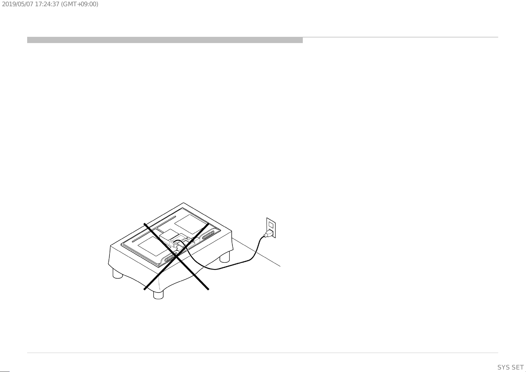
CARRYING THE TV
Be sure to follow these guidelines to protect your property and avoid causing serious injury.
• Carry the TV with an adequate number of people; larger size TVs require two or more people.
• Correct hand placement while carrying the TV is very important for safety and to avoid damages.
SAFETY-RELATED COMPONENT WARNING!!
Components identified by shading and ! mark on the schematic diagrams, exploded views, and in the parts list are critical for safe operation. Replace these components with Sony
parts whose part numbers appear as shown in this manual or in supplements published by Sony. Circuit adjustments that are critical for safe operation are identified in this manual.
Follow these procedures whenever critical components are replaced or improper operation is suspected.
CAUTION ABOUT THE LITHIUM BATTERY
• Danger of explosion if battery is incorrectly replaced. Replace only with the same or equivalent type.
• Outer case broken battery should not contact to water.
KD-55/65/75X8501C (FW-55/65/75X8570C), 8505C, 8507C, 8508C, 8509C
4
SYSSET
Page 5

2019/05/0717:24:37(GMT+09:00)
WARNINGS AND CAUTIONS - FRENCH
ATTENTION!!
Ces instructions de service sont à l’usage du personnel de service qualifi é seulement.
Pour prévenir le risque de choc électrique, ne pas faire l’entretien autre que celui contenu dans le Mode d’emploi à moins que vous soyez qualifi é faire ainsi.
WARNING!!
Afi n d’eviter tout risque d’electrocution provenant d’un chássis sous tension, un transformateur d’isolement doit etre utilisé lors de tout dépannage. Le chássis de ce récepteur est
directement raccordé à l’alimentation du secteur.
POUR TRANSPORTER LE TÉLÉVISEUR
Tenez compte de ce qui suit pendant l’installation du téléviseur :
• Débranchez tous les câbles avant de transporter le téléviseur.
• Transportez le téléviseur avec le nombre de personnes approprié ; un téléviseur de grande taille doit être transporté par au moins deux personnes.
• Lors du transport du téléviseur, l’emplacement des mains est très important pour votre sécurité, ainsi que pour éviter de causer des dommages.
ALERTE!!
Afi n d’eviter tout risque d’electrocution provenant d’un chassis sous tension, un transformateur d’isolement doit etre utilise lors de tout depannage. Le chassis de ce recepteur est
directement raccorde a l’alimentation du secteur.
ATTENTION AUX COMPOSANTS RELATIFS A LA SECURITE!!
Les composants identifi es par une trame et par une marque ! sur les schemas de principe, les vues explosees et les listes de pieces sont d’une importance critique pour la securite du
fonctionnement. Ne les remplacer que par des composants Sony dont le numero de piece est indique dans le present manuel ou dans des supplements publies par Sony. Les reglages
de circuit dont l’importance est critique pour la securite du fonctionnement sont identifi es dans le present manuel. Suivre ces procedures lors de chaque remplacement de
composants critiques, ou lorsqu’un mauvais fonctionnement suspecte.
KD-55/65/75X8501C (FW-55/65/75X8570C), 8505C, 8507C, 8508C, 8509C
5
SYSSET
Page 6
2019/05/0717:24:37(GMT+09:00)
USE CAUTION WHEN HANDLING THE LCD PANEL
When repairing the LCD panel, be sure you are grounded by using a wrist band.
When repairing the LCD panel on the wall, the LCD panel must be secured using the 4 mounting holes on the rear cover.
1) Do not press on the panel or frame edge to avoid the risk of electric shock.
2) Do not scratch or press on the panel with any sharp objects.
3) Do not leave the module in high temperatures or in areas of high humidity for an extended period of time.
4) Do not expose the LCD panel to direct sunlight.
5) Avoid contact with water. It may cause a short circuit within the module.
6) Disconnect the AC power when replacing the backlight (CCFL) or inverter circuit. (High voltage occurs at the inverter circuit at 650Vrms.)
7) Always clean the LCD panel with a soft cloth material.
8) Use care when handling the wires or connectors of the inverter circuit. Damaging the wires may cause a short.
9) Protect the panel from ESD to avoid damaging the electronic circuit (C-MOS).
10) It is recommended not to exceed 1 hour of Power-On nor Burn-in period with LCD panel face down condition, in repair activity.
WARNINGS AND CAUTIONS
KD-55/65/75X8501C (FW-55/65/75X8570C), 8505C, 8507C, 8508C, 8509C
6
SYSSET
Page 7

2019/05/0717:24:37(GMT+09:00)
SAFETY CHECK-OUT
After correcting the original service problem, perform the following safety checks before releasing the set to the customer:
1. Check the area of your repair for unsoldered or poorly soldered connections. Check the entire board surface for solder splashes and bridges.
2. Check the interboard wiring to ensure that no wires are “pinched” or touching high-wattage resistors.
3. Check that all control knobs, shields, covers, ground straps, and mounting hardware have been replaced. Be absolutely certain that you have replaced all the insulators.
4. Look for unauthorized replacement parts, particularly transistors, that were installed during a previous repair. Point them out to the customer and recommend their replacement.
5. Look for parts which, though functioning, show obvious signs of deterioration. Point them out to the customer and recommend their replacement.
6. Check the line cords for cracks and abrasion. Recommend the replacement of any such line cord to the customer.
7. Check the antenna terminals, metal trim, “metallized” knobs, screws, and all other exposed metal parts for AC leakage. Check leakage as described below.
8. For safety reasons, repairing the Power board and/or Inverter board is prohibited.
KD-55/65/75X8501C (FW-55/65/75X8570C), 8505C, 8507C, 8508C, 8509C
7
SYSSET
Page 8
2019/05/0717:24:37(GMT+09:00)
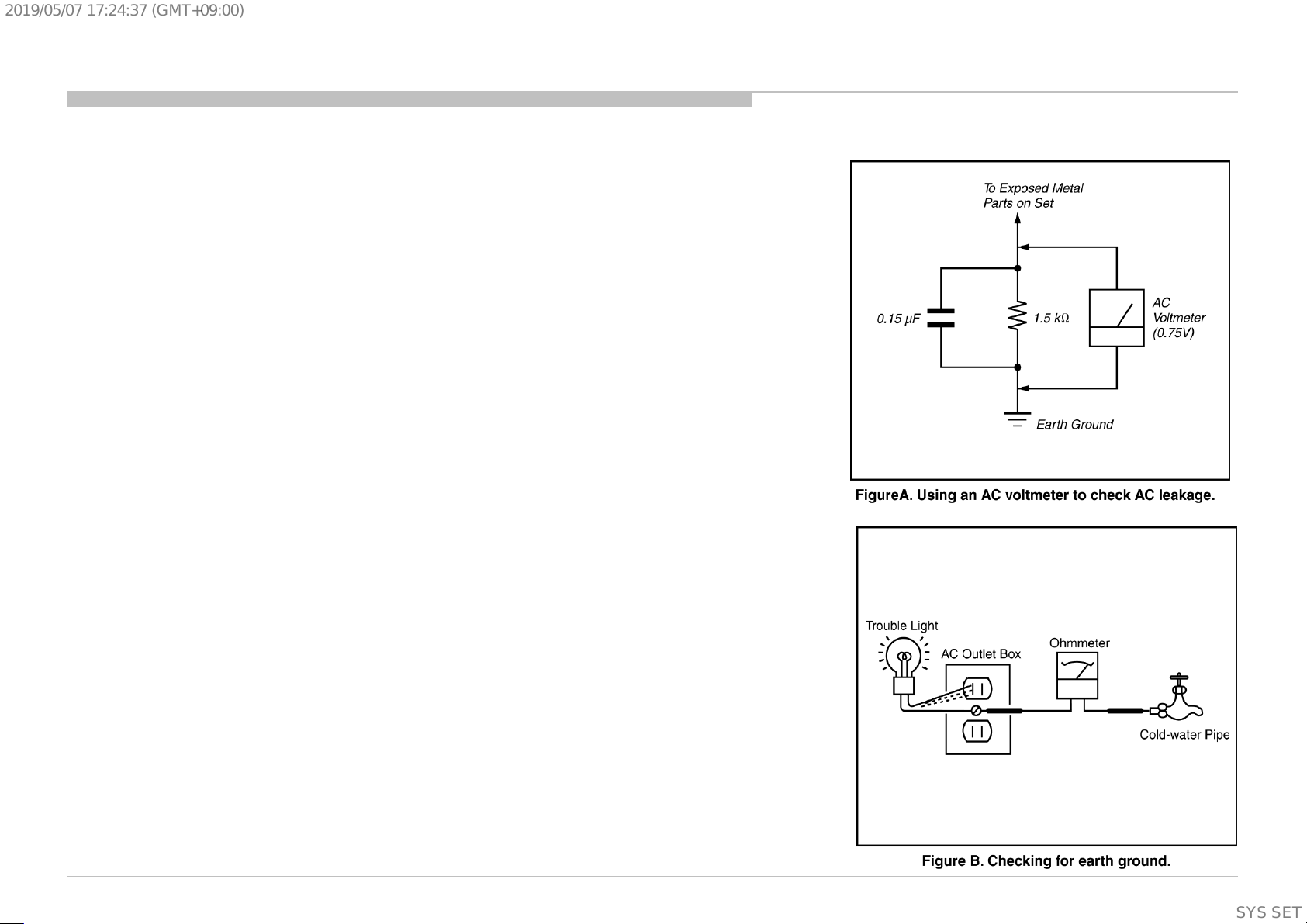
Leakage Test
The AC leakage from any exposed metal part to earth ground and from all exposed metal parts to any exposed
metal part having a return to chassis, must not exceed 0.5 mA (500 microamperes).
Leakage current can be measured by any one of three methods.
1. A commercial leakage tester, such as the Simpson 229 or RCA WT-540A. Follow the manufacturers’
instructions to use these instructions.
2. A battery-operated AC milliampmeter. The Data Precision 245 digital multimeter is suitable for this job.
3. Measuring the voltage drop across a resistor by means of a VOM or battery-operated AC voltmeter. The
“limit” indication is 0.75 V, so analog meters must have an accurate low voltage scale.
The Simpson’s 250 and Sanwa SH-63TRD are examples of passive VOMs that are suitable. Nearly all
battery-operated digital multimeters that have a 2 VAC range are suitable (see Figure A).
How to Find a Good Earth Ground
A cold-water pipe is a guaranteed earth ground; the cover-plate retaining screw on most AC outlet boxes is also
at earth ground.
If the retaining screw is to be used as your earth ground, verify that it is at ground by measuring the resistance
between it and a cold-water pipe with an ohmmeter. The reading should be zero ohms.
If a cold-water pipe is not accessible, connect a 60- to 100-watt trouble- light (not a neon lamp) between the hot
side of the receptacle and the retaining screw. Try both slots, if necessary, to locate the hot side on the line; the
lamp should light at normal brilliance if the screw is at ground potential (see Figure B).
SAFETY CHECK-OUT
KD-55/65/75X8501C (FW-55/65/75X8570C), 8505C, 8507C, 8508C, 8509C
8
SYSSET
Page 9

2019/05/0717:24:37(GMT+09:00)
SELF DIAGNOSIS FUNCTION
The units in this manual contain a self-diagnostic function. If an error occurs, the Smart Core Red LED will automatically begin to flash.
The number of times the LED flashes translates to a probable source of the problem.
A definition of the Smart Core Red LED flash indicators is listed in the instruction manual for the user’s knowledge and reference.
If an error symptom cannot be reproduced, the remote commander can be used to review the failure occurrence data stored in memory to reveal past problems and how often these
problems occur.
DIAGNOSTIC TEST INDICATORS
When an error occurs, the Smart Core Red LED will flash a set number of times to indicate the possible cause of the problem.
If there is more than one error, the LED will identify the first of the problem areas.
Result for all of the following diagnostic items are displayed on screen.
If the screen displays a “0”, no error has occurred .
RED LED blinking count Detection Items
2x
<G>: Power supply board, <B>: Main board, <T>: Tcon board,
<P>: Panel module , <S>: Speaker , <A>: Power Adapter
<G/B> Main 12V over voltage [MAIN_POWER]
<B> Main 5.0V failure [DC_ALERT]
<B/S> Audio amp. protection [AUD_ERR]
3x
4x None
5x
6x <G/P/B> Backlight failure [BACKLIGHT]
7x
8x <B> Software error [SW_ERR]
Red italic: detect at startup sequence only.
KD-55/65/75X8501C (FW-55/65/75X8570C), 8505C, 8507C, 8508C, 8509C
<B> Tuner or demodulator I2C No ACK [TU_DEMOD] [Note.1]
<B> HDMI Switch/Equalizer I2C communication error [HDMI_EQ] [Note.2]
Note.1/Note.2: Both functions were disabled but remains on the Self diagnosis screen like in the next page.
Note.2: Some of the sets in XF/XFL/XS/XB segment only for UK destination have the HDMI error detection function enabled.
Among these, software version updated or installed to PKG2177 or higher have this function disabled.
<P/T/G/B> Panel ID EEPROM I2C No ACK (Also panel power failure is a suspect) [P_ID_ERR]
<T> TCon IC I2C communication error [TCON_ERR]
Over temperature protection [TEMP_ERR]
<B> Temp. sensor I2C No ACK [TEMP_ERR]
<B> V By One lock error between Main device and 4KBE device [4KBE_ERR]
9
SYSSET
Page 10
2019/05/0717:24:37(GMT+09:00)
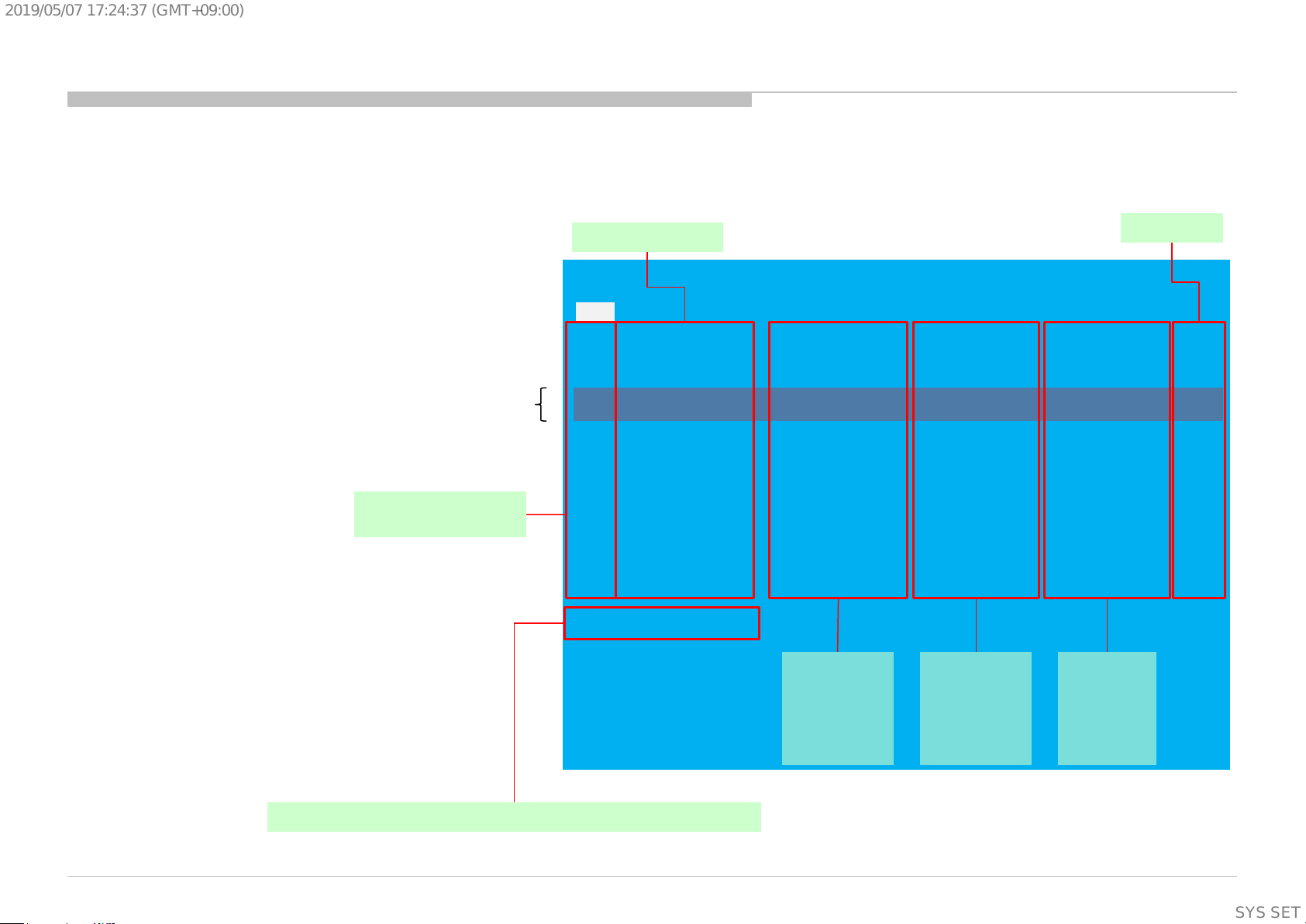
[SELF DIAGNOSTIC SCREEN DISPLAY]
SELF DIAGNOSIS FUNCTION
Format of error timestamps
YYMMDDhhmmss (in UTC)
Example:
120823132523 -> Aug 23 2012 13:25:23 UTC
* Only when time is set, an error timestamp
is saved.
Both of HDMI_EQ/TU_DEMOD have been disabled.
(Refer the previous page for details.)
The number indicated here has no meaning.
Smart Core Red LED
blinking count
•Panel Operation Time is recorded every
30 min, but Total Operation Time is recorded every 1 hr.
Therefore, the panel op. time might become larger than
the total op. time.
Error item Naming
Error count
SELF CHECK
Back
<<
002 MAIN_POWER 000000000000 000000000000 000000000000 000
003 DC_ALERT 000000000000 000000000000 000000000000 000
003 AUD_ERR 150101000018 150101000018 150101000018 003
003 HDMI_EQ 150101000123 150101000045 150101000045 003
003 TU_DEMOD 150101000218 150101000223 150101000105 003
004 LD_ERR 000000000000 000000000000 000000000000 000
004 BCM_ERR 000000000000 000000000000 000000000000 000
005 TCON_ERR 150101000504 000000000000 000000000000 001
005 P_ID_ERR 000000000000 000000000000 000000000000 000
006 BACKLIGHT ERR 000000000000 000000000000 000000000000 000
007 TEMP_ERR 150101000200 150101000002 000000000000 002
007 4KBE_ERR 000000000000 000000000000 000000000000 000
008 SW_ERR 000000000000 000000000000 000000000000 000
00005 00414 00002
[Home]Exit
Error
timestamp for
last recorded
error
Error
timestamp for
second last
recorded error
Error
timestamp
for 3rd last
recorded
error
Total Operation Time [hr] – Boot Count – Panel Operation Time [hr]
KD-55/65/75X8501C (FW-55/65/75X8570C), 8505C, 8507C, 8508C, 8509C
10
SYSSET
Page 11
2019/05/0717:24:37(GMT+09:00)
SELF-DIAGNOSTIC SCREEN DISPLAY
For errors with symptoms such as “power sometimes shuts off” or “screen sometimes goes out” that cannot be confirmed, it is possible to bring up past occurrences of failure for
confirmation on the screen:
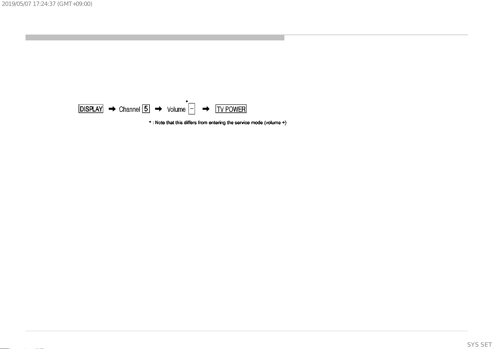
[To Bring Up Screen Test]
In standby mode, press buttons on the remote commander sequentially in rapid succession as shown below:
Since the diagnostic results displayed on the screen are not automatically cleared, always check the self-diagnostic screen.
After you have completed the repairs, clear the result display to “0”.
Clearing the Self Check Diagnostic List
Panel operation time : Press the Channel 7 => Channel 0 .
*Note that this model does not have the function to clear the result display to “0” ,which was possible in the conventional models
by the operation of “press the Channel 8=>Channel 0”
Exiting the Self-diagnostic screen
To exit the Self Diagnostic screen, Power off & on or Push the <Home> button.
SELF DIAGNOSIS FUNCTION
KD-55/65/75X8501C (FW-55/65/75X8570C), 8505C, 8507C, 8508C, 8509C
11
SYSSET
Page 12
2019/05/0717:24:37(GMT+09:00)
SEC 1. DISASSEMBLY
• There are clutch in the yellow frame[ ]. Therefore please b e careful in the case of the disassembly or assembly of parts.
1-1. KD-55X8501C (FW-55X8570C)/8505C/8507C/8508C/8509C
1-1-1. STAND (L HRN) A
4 screws (SCREW, +PSW M5X16) P/N: 4-449-743-01
Screw (SCREW, +PSW M5X16)
P/N: 4-449-743-01
NECK
KD-55/65/75X8501C (FW-55/65/75X8570C), 8505C, 8507C, 8508C, 8509C
STAND
Screw (SCREW, +PSW M5X16)
P/N: 4-449-743-01
NECK
12
SYSSET
Page 13
2019/05/0717:24:37(GMT+09:00)
1-1. KD-55X8501C (FW-55X8570C)/8505C/8507C/8508C/8509C
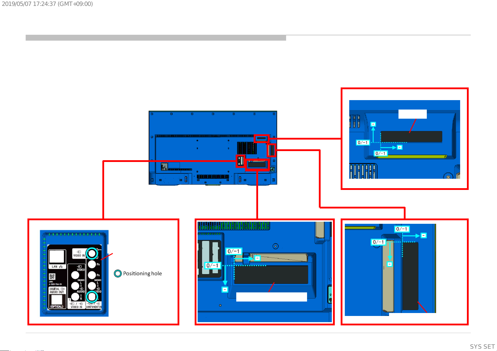
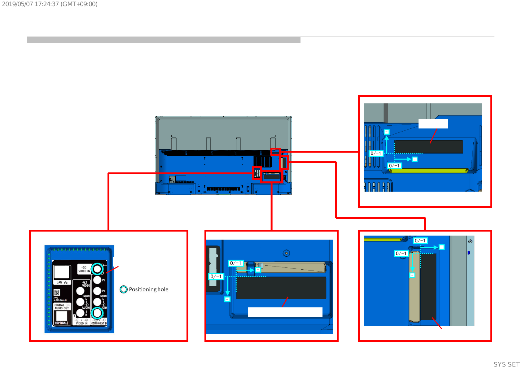
1-1-2. LABEL, UNDER TERMINAL AND LABEL, REAR TERMINAL AND LABEL, SIDE TERMINAL (L) AND LABEL, CI
DISASSEMBLY
LABEL, CI
LABEL, REAR TERMINAL
KD-55/65/75X8501C (FW-55/65/75X8570C), 8505C, 8507C, 8508C, 8509C
LABEL, UNDER TERMINAL
LABEL, SIDE TERMINAL (L)
13
SYSSET
Page 14
2019/05/0717:24:37(GMT+09:00)
1-1. KD-55X8501C (FW-55X8570C)/8505C/8507C/8508C/8509C
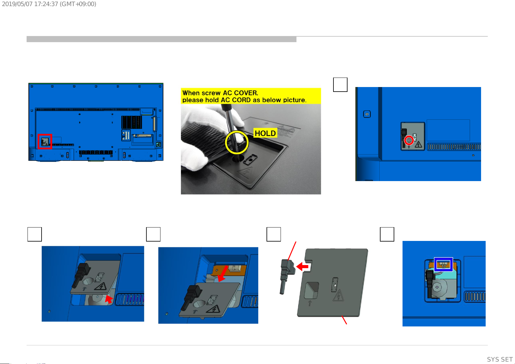
1-1-3. AC COVER AND POWER SUPPLY CORD
DISASSEMBLY
1
2 3 4
KD-55/65/75X8501C (FW-55/65/75X8570C), 8505C, 8507C, 8508C, 8509C
POWER SUPPLY CORD
AC COVER
Screw (SCREW +PSW M4X10) P/N: 4-159-298-01
5
14
SYSSET
Page 15
2019/05/0717:24:37(GMT+09:00)
1-1. KD-55X8501C (FW-55X8570C)/8505C/8507C/8508C/8509C
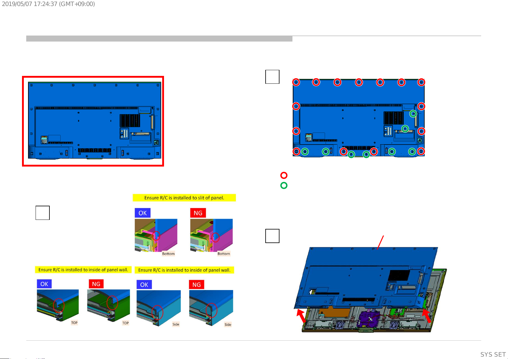
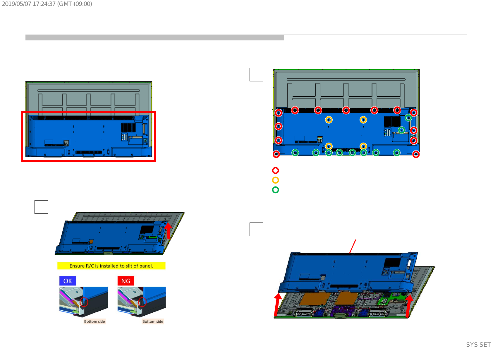
1-1-4. REAR COVER (L HRN) A
DISASSEMBLY
1
15 screws (SCREW , +PWH M3X6) P/N: 4-452-935-11
8 screws (SCREW, +BVTP 4X12 TYPE2 IT-3) P/N: 2-580-639-01
2
KD-55/65/75X8501C (FW-55/65/75X8570C), 8505C, 8507C, 8508C, 8509C
3
REAR COVER (L HRN) A
15
SYSSET
Page 16
2019/05/0717:24:37(GMT+09:00)
1-1. KD-55X8501C (FW-55X8570C)/8505C/8507C/8508C/8509C
DISASSEMBLY
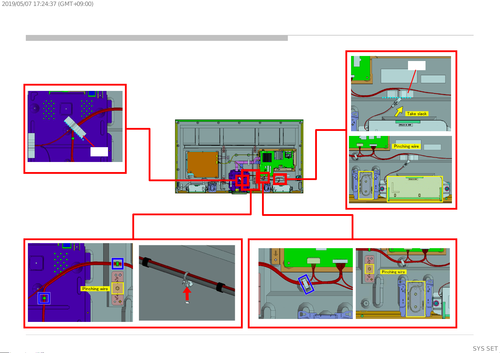
1-1-5. TAPE AND WIRE DRESSING
TAPE
TAPE
KD-55/65/75X8501C (FW-55/65/75X8570C), 8505C, 8507C, 8508C, 8509C
16
SYSSET
Page 17
2019/05/0717:24:37(GMT+09:00)
1-1. KD-55X8501C (FW-55X8570C)/8505C/8507C/8508C/8509C
1-1-6. TAPE AND WIRE DRESSING
DISASSEMBLY
KD-55/65/75X8501C (FW-55/65/75X8570C), 8505C, 8507C, 8508C, 8509C
TAPE
TAPE
17
SYSSET
Page 18
2019/05/0717:24:37(GMT+09:00)
1-1. KD-55X8501C (FW-55X8570C)/8505C/8507C/8508C/8509C
1-1-7. SPEAKER BOX ASSY (L)
DISASSEMBLY
1
2 3
KD-55/65/75X8501C (FW-55/65/75X8570C), 8505C, 8507C, 8508C, 8509C
SPEAKER BOX ASSY (L)
18
SYSSET
Page 19
2019/05/0717:24:37(GMT+09:00)
1-1. KD-55X8501C (FW-55X8570C)/8505C/8507C/8508C/8509C
1-1-8. SPEAKER BOX ASSY (R)
DISASSEMBLY
1
2 3
KD-55/65/75X8501C (FW-55/65/75X8570C), 8505C, 8507C, 8508C, 8509C
SPEAKER BOX ASSY (R)
19
SYSSET
Page 20
2019/05/0717:24:37(GMT+09:00)
1-1. KD-55X8501C (FW-55X8570C)/8505C/8507C/8508C/8509C
1-1-9. TAPE
DISASSEMBLY
TAPE
KD-55/65/75X8501C (FW-55/65/75X8570C), 8505C, 8507C, 8508C, 8509C
TAPE
TAPE
20
SYSSET
Page 21
2019/05/0717:24:37(GMT+09:00)
1-1. KD-55X8501C (FW-55X8570C)/8505C/8507C/8508C/8509C
1-1-10. BT ANTENNA
DISASSEMBLY
1
Screw (SCREW (+PSW)(M3X6))
P/N: 2-990-421-41
KD-55/65/75X8501C (FW-55/65/75X8570C), 8505C, 8507C, 8508C, 8509C
3 2
4
BT ANTENNA
21
SYSSET
Page 22
2019/05/0717:24:37(GMT+09:00)
1-1. KD-55X8501C (FW-55X8570C)/8505C/8507C/8508C/8509C
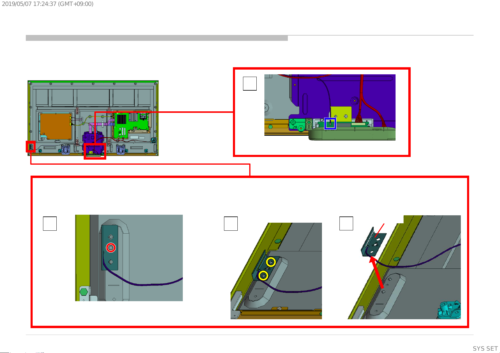
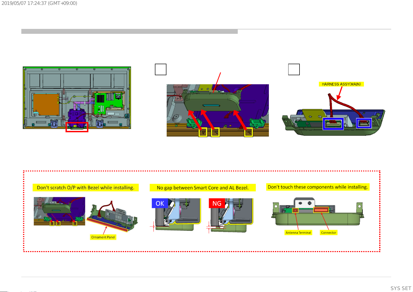
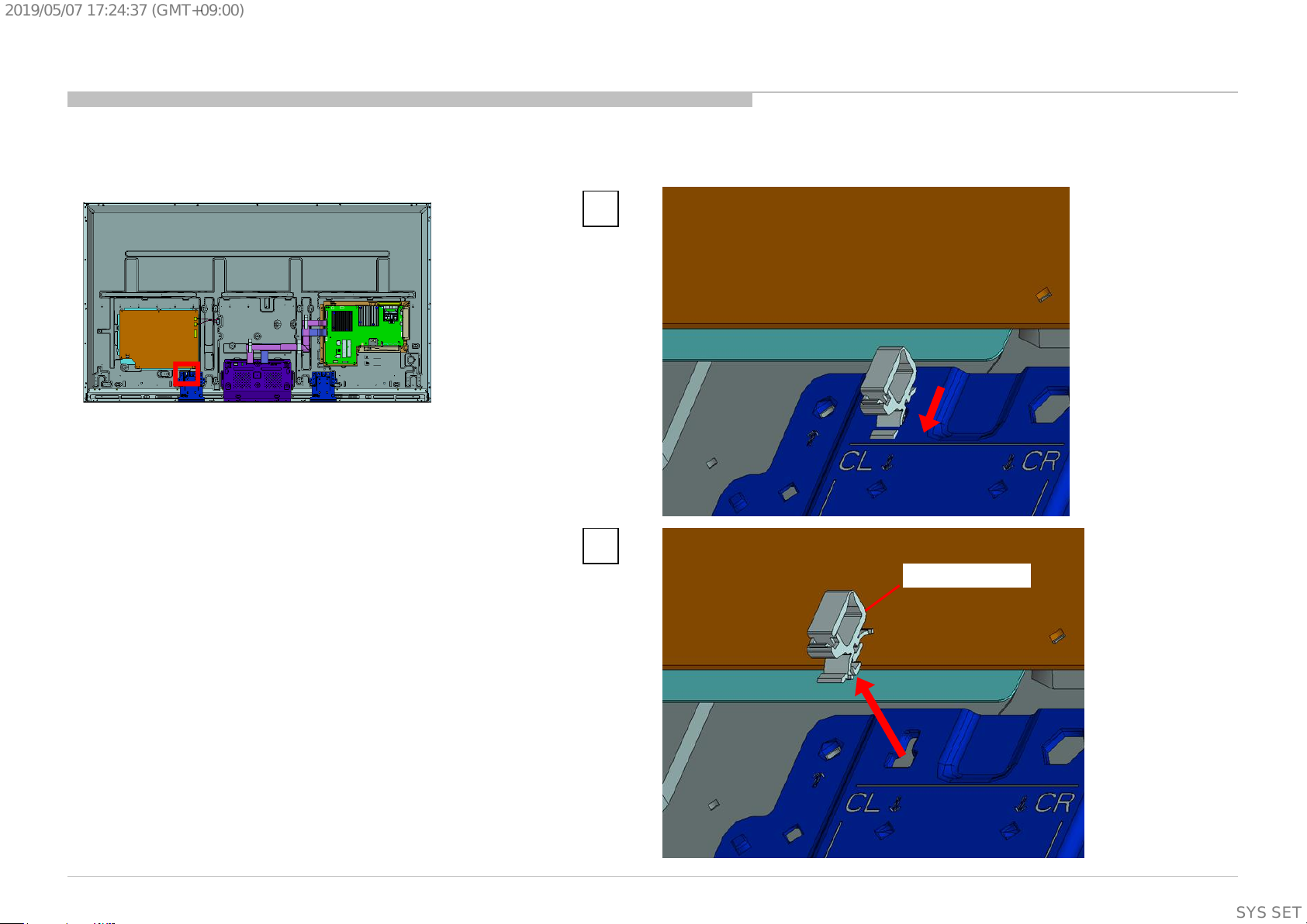
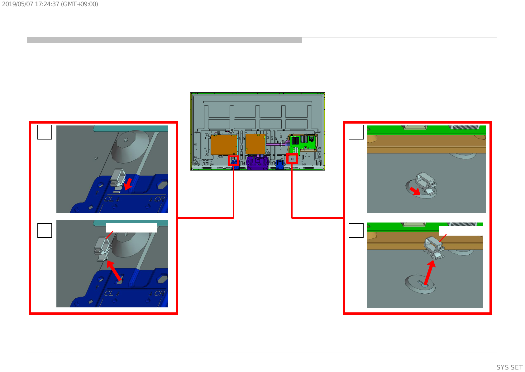
1-1-11. SMART CORE
DISASSEMBLY
Notes on assembling the Smart core
1 2
SMART CORE
KD-55/65/75X8501C (FW-55/65/75X8570C), 8505C, 8507C, 8508C, 8509C
22
SYSSET
Page 23
2019/05/0717:24:37(GMT+09:00)
1-1. KD-55X8501C (FW-55X8570C)/8505C/8507C/8508C/8509C
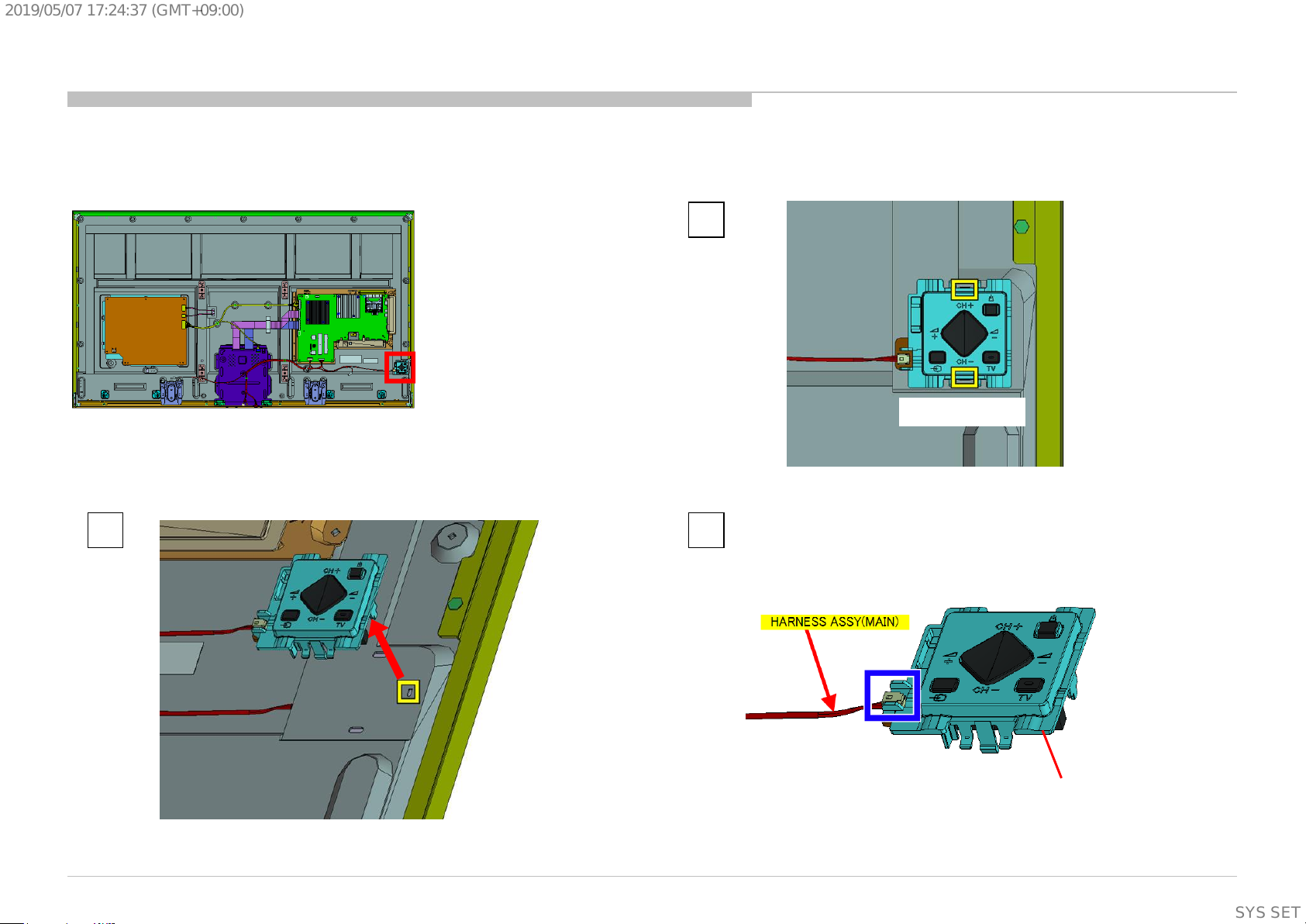
1-1-12. SWITCH UNIT
DISASSEMBLY
1
Release the lock
2 3
KD-55/65/75X8501C (FW-55/65/75X8570C), 8505C, 8507C, 8508C, 8509C
SWITCH UNIT
23
SYSSET
Page 24
2019/05/0717:24:37(GMT+09:00)
1-1. KD-55X8501C (FW-55X8570C)/8505C/8507C/8508C/8509C
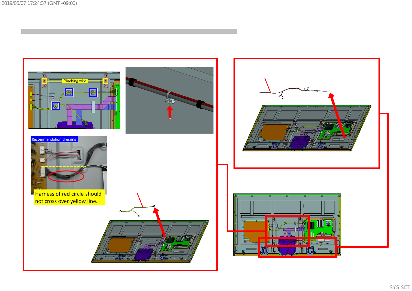
1-1-13. HARNESS ASSY (MAIN) AND CONNECTOR ASSY 28P
DISASSEMBLY
HARNESS ASSY (MAIN)
P/N: 1-910-110-24
CONNECTOR ASSY 28P
P/N: 1-910-110-23
KD-55/65/75X8501C (FW-55/65/75X8570C), 8505C, 8507C, 8508C, 8509C
24
SYSSET
Page 25
2019/05/0717:24:37(GMT+09:00)
1-1. KD-55X8501C (FW-55X8570C)/8505C/8507C/8508C/8509C
1-1-14. BRACKET,VESA(HWK)
DISASSEMBLY
1
2 3
KD-55/65/75X8501C (FW-55/65/75X8570C), 8505C, 8507C, 8508C, 8509C
8 screws (SCREW, +PSW M4X8) P/N: 2-580-600-11
BRACKET,VESA(HWK)
25
SYSSET
Page 26
2019/05/0717:24:37(GMT+09:00)
1-1. KD-55X8501C (FW-55X8570C)/8505C/8507C/8508C/8509C
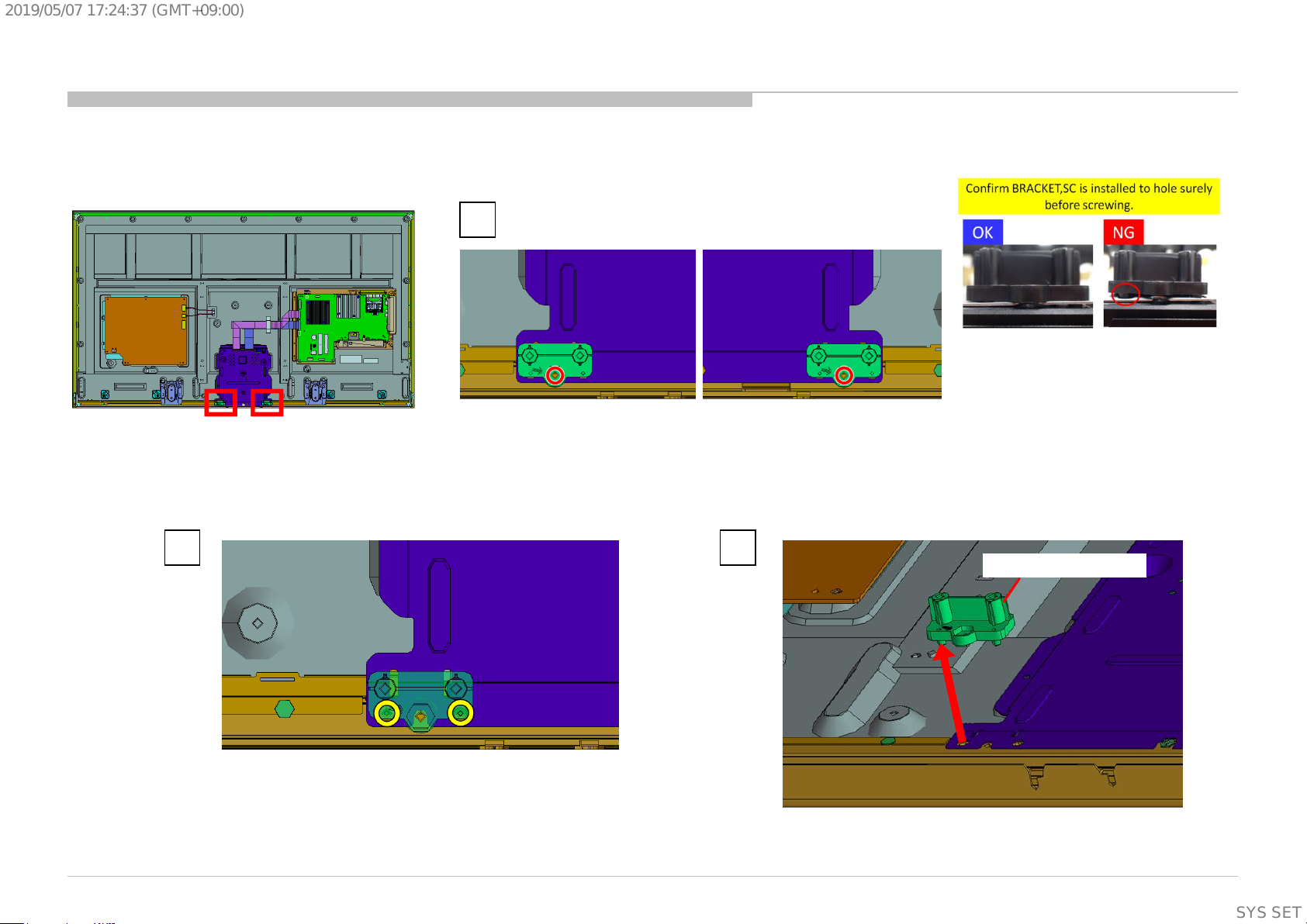
1-1-15. BRACKET, SC(HWK)
DISASSEMBLY
1
2 screws (SCREW (+PSW) (M3X6)) P/N: 2-990-421-41
KD-55/65/75X8501C (FW-55/65/75X8570C), 8505C, 8507C, 8508C, 8509C
3 2
BRACKET,SC(HWK)
26
SYSSET
Page 27
2019/05/0717:24:37(GMT+09:00)
1-1. KD-55X8501C (FW-55X8570C)/8505C/8507C/8508C/8509C
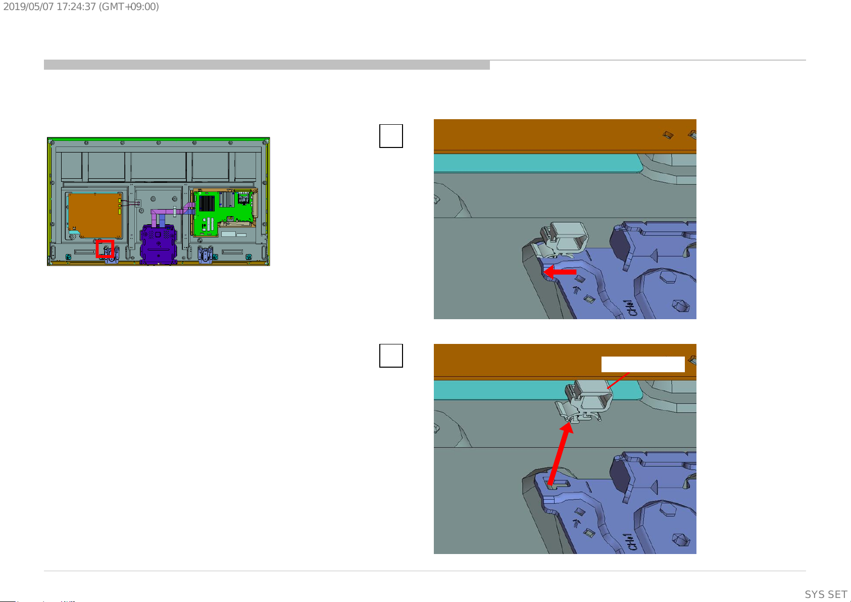
1-1-16. SLIDE, CLAMP
DISASSEMBLY
1
KD-55/65/75X8501C (FW-55/65/75X8570C), 8505C, 8507C, 8508C, 8509C
2
SLIDE, CLAMP
27
SYSSET
Page 28

2019/05/0717:24:37(GMT+09:00)
1-1. KD-55X8501C (FW-55X8570C)/8505C/8507C/8508C/8509C
1-1-17. BOTTOM, FRAME (HRN)
DISASSEMBLY
1
2
KD-55/65/75X8501C (FW-55/65/75X8570C), 8505C, 8507C, 8508C, 8509C
8 screws (SCREW, (+PSW)(M3X6)) P/N: 2-990-421-41
3
BOTTOM, FRAME (HRN)
28
SYSSET
Page 29
2019/05/0717:24:37(GMT+09:00)
1-1. KD-55X8501C (FW-55X8570C)/8505C/8507C/8508C/8509C
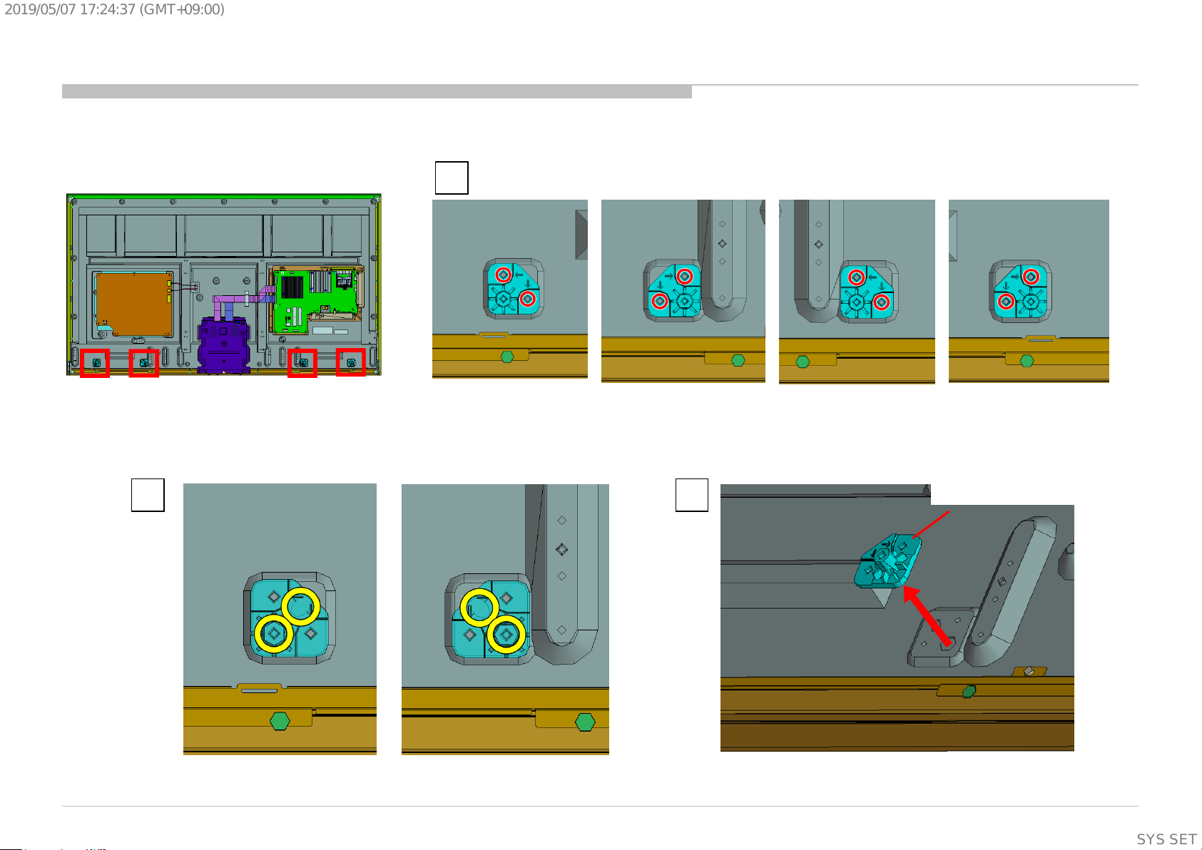
1-1-18. BRACKET, SP (LAK)
DISASSEMBLY
1
8 screws (SCREW, (+PSW)(M3X6)) P/N: 2-990-421-41
2
KD-55/65/75X8501C (FW-55/65/75X8570C), 8505C, 8507C, 8508C, 8509C
3
BRACKET, SP (LAK)
29
SYSSET
Page 30
2019/05/0717:24:37(GMT+09:00)
1-1. KD-55X8501C (FW-55X8570C)/8505C/8507C/8508C/8509C
1-1-19. GL3(CH)-STATIC CONVERTER(TV)
DISASSEMBLY
1
2 3
KD-55/65/75X8501C (FW-55/65/75X8570C), 8505C, 8507C, 8508C, 8509C
6 screws (SCREW, +PSW M3X6 W12) P/N: 4-256-393-11
GL3
30
SYSSET
Page 31

2019/05/0717:24:37(GMT+09:00)
1-1. KD-55X8501C (FW-55X8570C)/8505C/8507C/8508C/8509C
1-1-20. SHEET, INSULATION(HRN L)
(An insulation sheet is under the GL3 power supply board.)
DISASSEMBLY
1 2
SHEET, INSULATION(HRN L)
KD-55/65/75X8501C (FW-55/65/75X8570C), 8505C, 8507C, 8508C, 8509C
31
SYSSET
Page 32

2019/05/0717:24:37(GMT+09:00)
1-1. KD-55X8501C (FW-55X8570C)/8505C/8507C/8508C/8509C
1-1-21. FLEXIBLE FLAT CABLE 41P (XFS) AND FLEXIBLE FLAT CABLE 51P (XFS)
DISASSEMBLY
1
TAPE
FLEXIBLE FLAT CABLE 41P (XFS)
2 3
KD-55/65/75X8501C (FW-55/65/75X8570C), 8505C, 8507C, 8508C, 8509C
P/N: 1-848-927-11
FLEXIBLE FLAT CABLE 51P (XFS)
P/N: 1-848-922-11
32
SYSSET
Page 33

2019/05/0717:24:37(GMT+09:00)
1-1. KD-55X8501C (FW-55X8570C)/8505C/8507C/8508C/8509C
1-1-22. BRACKET, UNDER FL (MOLD)
DISASSEMBLY
1
2
KD-55/65/75X8501C (FW-55/65/75X8570C), 8505C, 8507C, 8508C, 8509C
3
BRACKET, UNDER FL (MOLD)
33
SYSSET
Page 34

2019/05/0717:24:37(GMT+09:00)
1-1. KD-55X8501C (FW-55X8570C)/8505C/8507C/8508C/8509C
1-1-23. BRACKET, SIDE FL (MOLD)
DISASSEMBLY
1
2
KD-55/65/75X8501C (FW-55/65/75X8570C), 8505C, 8507C, 8508C, 8509C
3
BRACKET, SIDE FL (MOLD)
34
SYSSET
Page 35

2019/05/0717:24:37(GMT+09:00)
1-1. KD-55X8501C (FW-55X8570C)/8505C/8507C/8508C/8509C
1-1-24. BRACKET, TOP FL (MOLD)
DISASSEMBLY
1
2
KD-55/65/75X8501C (FW-55/65/75X8570C), 8505C, 8507C, 8508C, 8509C
3
BRACKET, TOP FL (MOLD)
35
SYSSET
Page 36

2019/05/0717:24:37(GMT+09:00)
1-1. KD-55X8501C (FW-55X8570C)/8505C/8507C/8508C/8509C
1-1-25. PLATE, MAIN(HWK) ASSY
DISASSEMBLY
1
2
KD-55/65/75X8501C (FW-55/65/75X8570C), 8505C, 8507C, 8508C, 8509C
5 screws (SCREW, +PSW M3X8) P/N: 2-580-593-01
3
PLATE, MAIN(HWK) ASSY
36
SYSSET
Page 37

2019/05/0717:24:37(GMT+09:00)
1-1. KD-55X8501C (FW-55X8570C)/8505C/8507C/8508C/8509C
1-1-26. BMFL ASSY
DISASSEMBLY
1
2
KD-55/65/75X8501C (FW-55/65/75X8570C), 8505C, 8507C, 8508C, 8509C
3
9 screws (SCREW (+PSW)(M3X6)) P/N: 2-990-421-41
BMFL ASSY
37
SYSSET
Page 38

2019/05/0717:24:37(GMT+09:00)
1-1. KD-55X8501C (FW-55X8570C)/8505C/8507C/8508C/8509C
1-1-27. GASKET (BMF)
GASKET (BMF)
DISASSEMBLY
GASKET (BMF)
NOTE:
When you replace a BMFL board, it is necessary to stick five
new GASKETs on a new BMFL board.
GASKET (BMF): 4-566-117-01
But in below cases, GASKET is not necessary.
1. GASKET is soldered onto the surface of the board
2. In case below number is printed on the surface of the
B-board
"1-894-596-12 or 22“
(Please note that this is not the P/N of mounted board)
Stick GASKET inside the guide line.
Guide line
*No indication of direction
Caution:
1. Please aim at the center of square land.
2. Assy the gaskets just before B board panel installation.
KD-55/65/75X8501C (FW-55/65/75X8570C), 8505C, 8507C, 8508C, 8509C
To stick the GASKET firmly,
Press the gasket until compression completely.
(0.5-1.0kgf)
38
SYSSET
Page 39

2019/05/0717:24:37(GMT+09:00)
1-1. KD-55X8501C (FW-55X8570C)/8505C/8507C/8508C/8509C
1-1-28. SHEET, THERMAL(BM) AND PLATE, MAIN(HWK)
DISASSEMBLY
1
SHEET, THERMAL(BM))
2
KD-55/65/75X8501C (FW-55/65/75X8570C), 8505C, 8507C, 8508C, 8509C
PLATE, MAIN(HWK)
39
SYSSET
Page 40

2019/05/0717:24:37(GMT+09:00)
1-1. KD-55X8501C (FW-55X8570C)/8505C/8507C/8508C/8509C
1-1-29. SLIDE, CLAMP
DISASSEMBLY
1
KD-55/65/75X8501C (FW-55/65/75X8570C), 8505C, 8507C, 8508C, 8509C
2
SLIDE, CLAMP
40
SYSSET
Page 41

2019/05/0717:24:37(GMT+09:00)
1-1. KD-55X8501C (FW-55X8570C)/8505C/8507C/8508C/8509C
1-1-30. LCD PANEL
DISASSEMBLY
LCD PANEL
KD-55/65/75X8501C (FW-55/65/75X8570C), 8505C, 8507C, 8508C, 8509C
41
SYSSET
Page 42

2019/05/0717:24:37(GMT+09:00)
1-2. KD-65X8501C (FW-65X8570C)/8505C/8507C/8508C/8509C
1-2-1. STAND, SHAFT (2L HWK) A
DISASSEMBLY
4 screws (SCREW, +PSW M6X12) P/N: 4-567-081-01
2 screws (SCREW, +PSW M5X20)
P/N: 4-567-082-01
NECK
KD-55/65/75X8501C (FW-55/65/75X8570C), 8505C, 8507C, 8508C, 8509C
STAND
2 screws (SCREW, +PSW M5X20)
P/N: 4-567-082-01
NECK
42
SYSSET
Page 43
2019/05/0717:24:37(GMT+09:00)
1-2. KD-65X8501C (FW-65X8570C)/8505C/8507C/8508C/8509C
1-2-2. LABEL, UNDER TERMINAL AND LABEL, REAR TERMINAL AND LABEL, SIDE TERMINAL (L) AND LABEL, CI
DISASSEMBLY
LABEL, CI
LABEL, REAR TERMINAL
KD-55/65/75X8501C (FW-55/65/75X8570C), 8505C, 8507C, 8508C, 8509C
LABEL, UNDER TERMINAL
LABEL, SIDE TERMINAL (L)
43
SYSSET
Page 44

2019/05/0717:24:37(GMT+09:00)
1-2. KD-65X8501C (FW-65X8570C)/8505C/8507C/8508C/8509C
1-2-3. AC COVER AND POWER SUPPLY CORD
DISASSEMBLY
1
2 3 4
KD-55/65/75X8501C (FW-55/65/75X8570C), 8505C, 8507C, 8508C, 8509C
POWER SUPPLY CORD
AC COVER
Screw (SCREW +PSW M4X10) P/N: 4-159-298-01
5
44
SYSSET
Page 45

2019/05/0717:24:37(GMT+09:00)
1-2. KD-65X8501C (FW-65X8570C)/8505C/8507C/8508C/8509C
1-2-4. UNDER COVER (2L_HWK) A
2
DISASSEMBLY
1
12 screws (SCREW , +PWH M3X6) P/N: 4-452-935-11
4 screws (SCREW, ORNAMENTAL M6X12) P/N: 4-268-126-02
10 screws (SCREW, +BVTP 4X12 TYPE2 IT-3) P/N: 2-580-639-01
KD-55/65/75X8501C (FW-55/65/75X8570C), 8505C, 8507C, 8508C, 8509C
3
UNDER COVER (2L_HWK) A
45
SYSSET
Page 46

2019/05/0717:24:37(GMT+09:00)
1-2. KD-65X8501C (FW-65X8570C)/8505C/8507C/8508C/8509C
DISASSEMBLY
1-2-5. TAPE
TAPE
TAPE
TAPE
KD-55/65/75X8501C (FW-55/65/75X8570C), 8505C, 8507C, 8508C, 8509C
TAPE
TAPE
46
SYSSET
Page 47

2019/05/0717:24:37(GMT+09:00)
1-2. KD-65X8501C (FW-65X8570C)/8505C/8507C/8508C/8509C
1-2-6. TAPE
TAPE
DISASSEMBLY
KD-55/65/75X8501C (FW-55/65/75X8570C), 8505C, 8507C, 8508C, 8509C
TAPE
TAPE
47
SYSSET
Page 48

2019/05/0717:24:37(GMT+09:00)
1-2. KD-65X8501C (FW-65X8570C)/8505C/8507C/8508C/8509C
1-2-7. WIRE DRESSING
DISASSEMBLY
KD-55/65/75X8501C (FW-55/65/75X8570C), 8505C, 8507C, 8508C, 8509C
48
SYSSET
Page 49

2019/05/0717:24:37(GMT+09:00)
1-2. KD-65X8501C (FW-65X8570C)/8505C/8507C/8508C/8509C
1-2-8. SPEAKER BOX ASSY (L)
DISASSEMBLY
1
2 3
KD-55/65/75X8501C (FW-55/65/75X8570C), 8505C, 8507C, 8508C, 8509C
SPEAKER BOX ASSY (L)
49
SYSSET
Page 50

2019/05/0717:24:37(GMT+09:00)
1-2. KD-65X8501C (FW-65X8570C)/8505C/8507C/8508C/8509C
1-2-9. BRACKET, SP (2L HWK) A
DISASSEMBLY
1
4 screws (SCREW , +PSW M3X8) P/N: 2-580-593-01
2 3
KD-55/65/75X8501C (FW-55/65/75X8570C), 8505C, 8507C, 8508C, 8509C
BRACKET, SP (2L HWK) A
50
SYSSET
Page 51

2019/05/0717:24:37(GMT+09:00)
1-2. KD-65X8501C (FW-65X8570C)/8505C/8507C/8508C/8509C
1-2-10. SPEAKER BOX ASSY (R)
DISASSEMBLY
1
2 3
KD-55/65/75X8501C (FW-55/65/75X8570C), 8505C, 8507C, 8508C, 8509C
SPEAKER BOX ASSY (R)
51
SYSSET
Page 52

2019/05/0717:24:37(GMT+09:00)
1-2. KD-65X8501C (FW-65X8570C)/8505C/8507C/8508C/8509C
1-2-11. BRACKET, SP (2L HWK) A
DISASSEMBLY
1
2 3
KD-55/65/75X8501C (FW-55/65/75X8570C), 8505C, 8507C, 8508C, 8509C
4 screws (SCREW , +PSW M3X8) P/N: 2-580-593-01
BRACKET, SP (2L HWK) A
52
SYSSET
Page 53
2019/05/0717:24:37(GMT+09:00)
1-2. KD-65X8501C (FW-65X8570C)/8505C/8507C/8508C/8509C
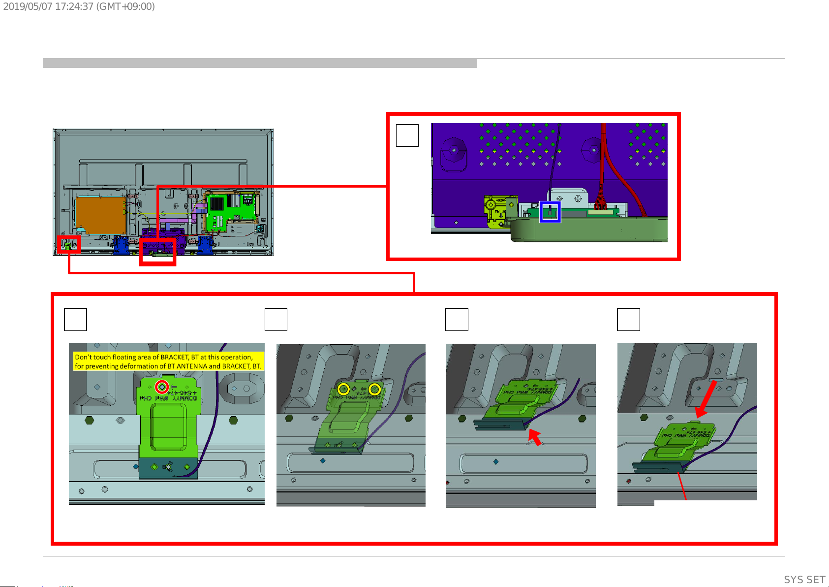
1-2-12. BRACKET,BT (EGL) ASSY
DISASSEMBLY
1
2
Screw (SCREW (+PSW)(M3X6))
P/N: 2-990-421-41
KD-55/65/75X8501C (FW-55/65/75X8570C), 8505C, 8507C, 8508C, 8509C
3 4 5
BRACKET,BT (EGL) ASSY
53
SYSSET
Page 54

2019/05/0717:24:37(GMT+09:00)
1-2. KD-65X8501C (FW-65X8570C)/8505C/8507C/8508C/8509C
1-2-13. BT ANTENNA AND BRACKET, BT(EGL)
DISASSEMBLY
1 2
Screw (SCREW (+PSW)(M3X6))
P/N: 2-990-421-41
3 4
KD-55/65/75X8501C (FW-55/65/75X8570C), 8505C, 8507C, 8508C, 8509C
BT ANTENNA
BRACKET,BT (EGL)
54
SYSSET
Page 55

2019/05/0717:24:37(GMT+09:00)
1-2. KD-65X8501C (FW-65X8570C)/8505C/8507C/8508C/8509C
1-2-14. SMART CORE
DISASSEMBLY
Notes on assembling the Smart core
1 2
SMART CORE
KD-55/65/75X8501C (FW-55/65/75X8570C), 8505C, 8507C, 8508C, 8509C
55
SYSSET
Page 56

2019/05/0717:24:37(GMT+09:00)
1-2. KD-65X8501C (FW-65X8570C)/8505C/8507C/8508C/8509C
1-2-15. SWITCH UNIT
DISASSEMBLY
1
Release the lock
2 3
KD-55/65/75X8501C (FW-55/65/75X8570C), 8505C, 8507C, 8508C, 8509C
SWITCH UNIT
56
SYSSET
Page 57

2019/05/0717:24:37(GMT+09:00)
1-2. KD-65X8501C (FW-65X8570C)/8505C/8507C/8508C/8509C
1-2-16. HARNESS ASSY (MAIN) AND CONNECTOR ASSY 28P
DISASSEMBLY
HARNESS ASSY (MAIN)
P/N: 1-910-109-96
CONNECTOR ASSY 28P
P/N: 1-910-109-95
KD-55/65/75X8501C (FW-55/65/75X8570C), 8505C, 8507C, 8508C, 8509C
57
SYSSET
Page 58
2019/05/0717:24:37(GMT+09:00)
1-2. KD-65X8501C (FW-65X8570C)/8505C/8507C/8508C/8509C
1-2-17. BRACKET,VESA(HWK)
DISASSEMBLY
1
2 3
KD-55/65/75X8501C (FW-55/65/75X8570C), 8505C, 8507C, 8508C, 8509C
8 screws (SCREW, +PSW M4X8) P/N: 2-580-600-11
BRACKET,VESA(HWK)
58
SYSSET
Page 59

2019/05/0717:24:37(GMT+09:00)
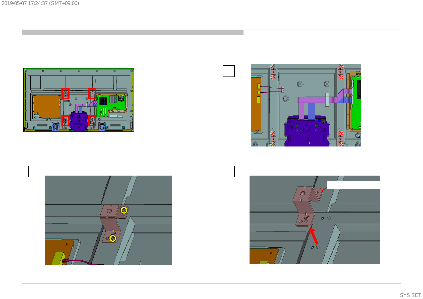
1-2. KD-65X8501C (FW-65X8570C)/8505C/8507C/8508C/8509C
1-2-18. BRACKET, SC(HWK)
DISASSEMBLY
1
4 screws (SCREW, +PSW M3X8) P/N: 2-580-593-01
KD-55/65/75X8501C (FW-55/65/75X8570C), 8505C, 8507C, 8508C, 8509C
3 2
BRACKET,SC(HWK)
59
SYSSET
Page 60
2019/05/0717:24:37(GMT+09:00)
1-2. KD-65X8501C (FW-65X8570C)/8505C/8507C/8508C/8509C
1-2-19. SLIDE, CLAMP
DISASSEMBLY
1
KD-55/65/75X8501C (FW-55/65/75X8570C), 8505C, 8507C, 8508C, 8509C
2
SLIDE, CLAMP
60
SYSSET
Page 61

2019/05/0717:24:37(GMT+09:00)
1-2. KD-65X8501C (FW-65X8570C)/8505C/8507C/8508C/8509C
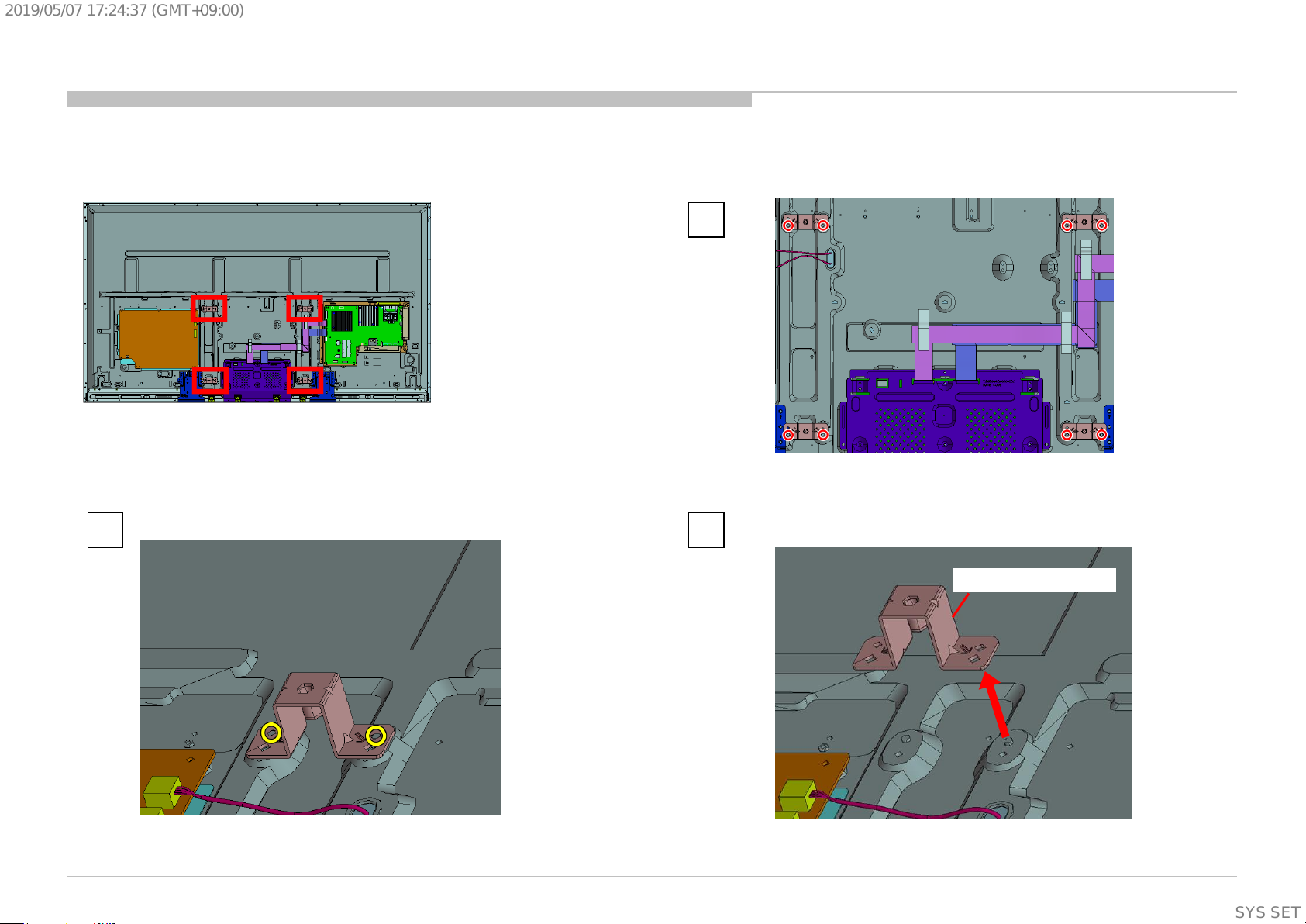
1-2-20. BRACKET, STD C (2L_HWK) AND GASKET (HWK STD)
DISASSEMBLY
3
BRACKET, STD C(2L_HWK)
1
2 screws (PULLEY, STAND (HWI)) P/N: 4-534-964-01 8 screws (SCREW, +PSW M4X8) P/N: 2-580-600-11
2
4
KD-55/65/75X8501C (FW-55/65/75X8570C), 8505C, 8507C, 8508C, 8509C
GASKET (HWK STD)
61
SYSSET
Page 62

2019/05/0717:24:37(GMT+09:00)
1-2. KD-65X8501C (FW-65X8570C)/8505C/8507C/8508C/8509C
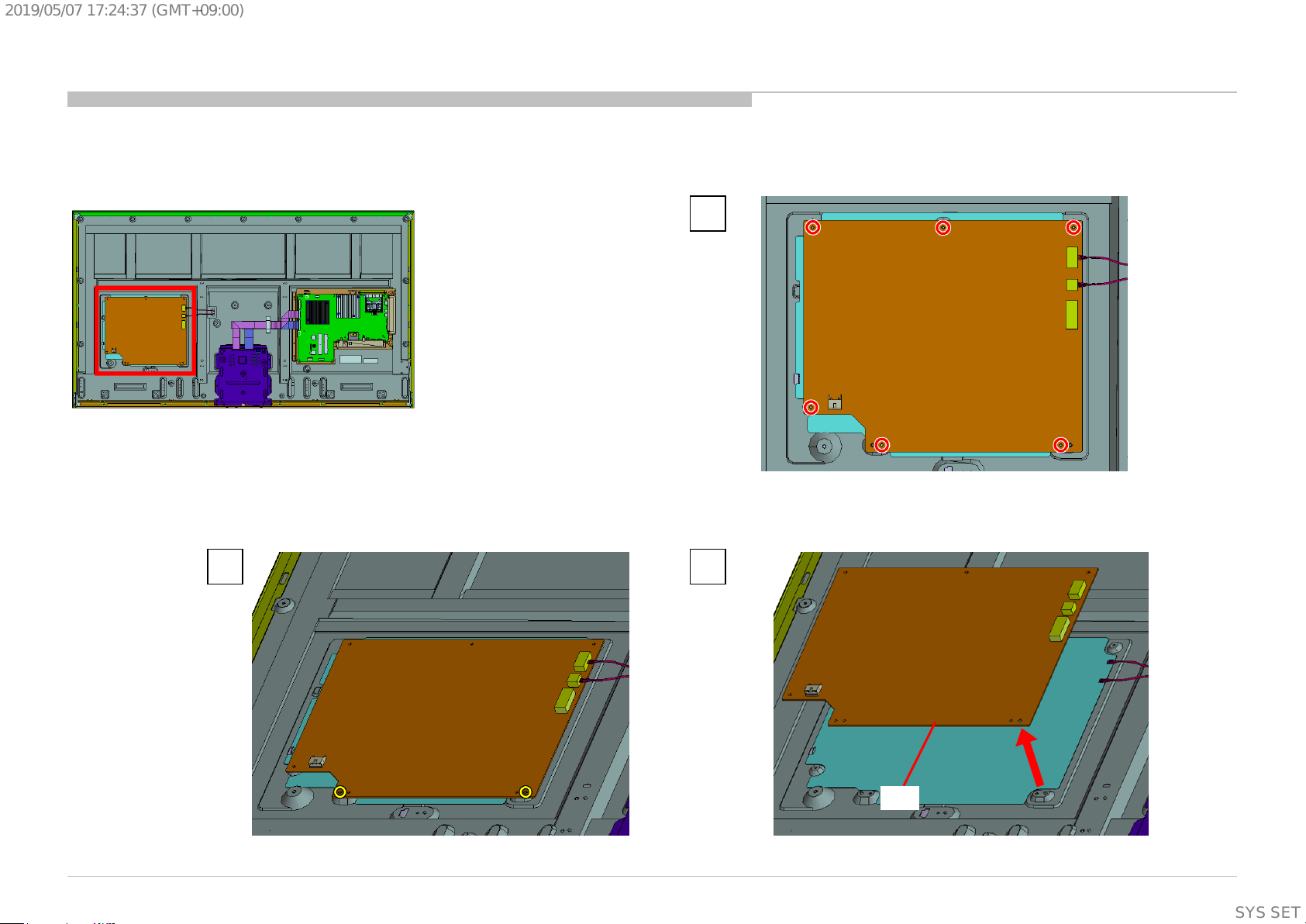
1-2-21. GL1A(CH)-STATIC CONVERTER(TV)
DISASSEMBLY
2
6 screws (SCREW, +PSW M3X6 W12) P/N: 4-256-393-11
KD-55/65/75X8501C (FW-55/65/75X8570C), 8505C, 8507C, 8508C, 8509C
3 1
GL1A
62
SYSSET
Page 63

2019/05/0717:24:37(GMT+09:00)
1-2. KD-65X8501C (FW-65X8570C)/8505C/8507C/8508C/8509C
1-2-22. SHEET, INSULATION(HWK 2L)
(An insulation sheet is under the GL1A power supply board.)
DISASSEMBLY
1 2
SHEET, INSULATION(HWK 2L)
KD-55/65/75X8501C (FW-55/65/75X8570C), 8505C, 8507C, 8508C, 8509C
63
SYSSET
Page 64

2019/05/0717:24:37(GMT+09:00)
1-2. KD-65X8501C (FW-65X8570C)/8505C/8507C/8508C/8509C
1-2-23. TAPE
DISASSEMBLY
TAPE
TAPE
KD-55/65/75X8501C (FW-55/65/75X8570C), 8505C, 8507C, 8508C, 8509C
TAPE
64
SYSSET
Page 65

2019/05/0717:24:37(GMT+09:00)
1-2. KD-65X8501C (FW-65X8570C)/8505C/8507C/8508C/8509C
1-2-24. CABLE, FLEXIBLE FLAT 41P AND CABLE, FLEXIBLE FLAT 51P
DISASSEMBLY
1 2
KD-55/65/75X8501C (FW-55/65/75X8570C), 8505C, 8507C, 8508C, 8509C
CABLE, FLEXIBLE FLAT 41P
P/N: 1-848-872-11
CABLE, FLEXIBLE FLAT 51P
P/N: 1-848-873-11
65
SYSSET
Page 66

2019/05/0717:24:37(GMT+09:00)
1-2. KD-65X8501C (FW-65X8570C)/8505C/8507C/8508C/8509C
1-2-25. BRACKET, UNDER FL (MOLD)
DISASSEMBLY
1
2
KD-55/65/75X8501C (FW-55/65/75X8570C), 8505C, 8507C, 8508C, 8509C
3
BRACKET, UNDER FL (MOLD)
66
SYSSET
Page 67

2019/05/0717:24:37(GMT+09:00)
1-2. KD-65X8501C (FW-65X8570C)/8505C/8507C/8508C/8509C
1-2-26. BRACKET, SIDE FL (MOLD)
DISASSEMBLY
1
2
KD-55/65/75X8501C (FW-55/65/75X8570C), 8505C, 8507C, 8508C, 8509C
3
BRACKET, SIDE FL (MOLD)
67
SYSSET
Page 68

2019/05/0717:24:37(GMT+09:00)
1-2. KD-65X8501C (FW-65X8570C)/8505C/8507C/8508C/8509C
1-2-27. BRACKET, TOP FL (MOLD)
DISASSEMBLY
1
2
KD-55/65/75X8501C (FW-55/65/75X8570C), 8505C, 8507C, 8508C, 8509C
3
BRACKET, TOP FL (MOLD)
68
SYSSET
Page 69

2019/05/0717:24:37(GMT+09:00)
1-2. KD-65X8501C (FW-65X8570C)/8505C/8507C/8508C/8509C
1-2-28. PLATE, MAIN(HWK) ASSY
DISASSEMBLY
1
2
KD-55/65/75X8501C (FW-55/65/75X8570C), 8505C, 8507C, 8508C, 8509C
3
5 screws (SCREW, +PSW M3X8) P/N: 2-580-593-01
PLATE, MAIN(HWK) ASSY
69
SYSSET
Page 70

2019/05/0717:24:37(GMT+09:00)
1-2. KD-65X8501C (FW-65X8570C)/8505C/8507C/8508C/8509C
1-2-29. BMFL ASSY
DISASSEMBLY
1
2
KD-55/65/75X8501C (FW-55/65/75X8570C), 8505C, 8507C, 8508C, 8509C
3
9 screws (SCREW (+PSW)(M3X6)) P/N: 2-990-421-41
BMFL ASSY
70
SYSSET
Page 71

2019/05/0717:24:37(GMT+09:00)
1-2. KD-65X8501C (FW-65X8570C)/8505C/8507C/8508C/8509C
1-2-30. GASKET (BMF)
GASKET (BMF)
DISASSEMBLY
GASKET (BMF)
NOTE:
When you replace a BMFL board, it is necessary to stick five
new GASKETs on a new BMFL board.
GASKET (BMF): 4-566-117-01
But in below cases, GASKET is not necessary.
1. GASKET is soldered onto the surface of the board
2. In case below number is printed on the surface of the
B-board
"1-894-596-12 or 22“
(Please note that this is not the P/N of mounted board)
Stick GASKET inside the guide line.
Guide line
*No indication of direction
Caution:
1. Please aim at the center of square land.
2. Assy the gaskets just before B board panel installation.
KD-55/65/75X8501C (FW-55/65/75X8570C), 8505C, 8507C, 8508C, 8509C
To stick the GASKET firmly,
Press the gasket until compression completely.
(0.5-1.0kgf)
71
SYSSET
Page 72

2019/05/0717:24:37(GMT+09:00)
1-2. KD-65X8501C (FW-65X8570C)/8505C/8507C/8508C/8509C
1-2-31. SHEET, THERMAL(BM) AND PLATE, MAIN(HWK)
DISASSEMBLY
1
SHEET, THERMAL(BM))
2
KD-55/65/75X8501C (FW-55/65/75X8570C), 8505C, 8507C, 8508C, 8509C
PLATE, MAIN(HWK)
72
SYSSET
Page 73

2019/05/0717:24:37(GMT+09:00)
1-2. KD-65X8501C (FW-65X8570C)/8505C/8507C/8508C/8509C
1-2-32. CUSHION, CORNER(EGL) AND TAPE
DISASSEMBLY
TAPE
TAPE
TAPE
CUSHION, CORNER(EGL) CUSHION, CORNER(EGL)
KD-55/65/75X8501C (FW-55/65/75X8570C), 8505C, 8507C, 8508C, 8509C
73
SYSSET
Page 74

2019/05/0717:24:37(GMT+09:00)
1-2. KD-65X8501C (FW-65X8570C)/8505C/8507C/8508C/8509C
1-2-33. LCD PANEL
DISASSEMBLY
LCD PANEL
KD-55/65/75X8501C (FW-55/65/75X8570C), 8505C, 8507C, 8508C, 8509C
74
SYSSET
Page 75

2019/05/0717:24:37(GMT+09:00)
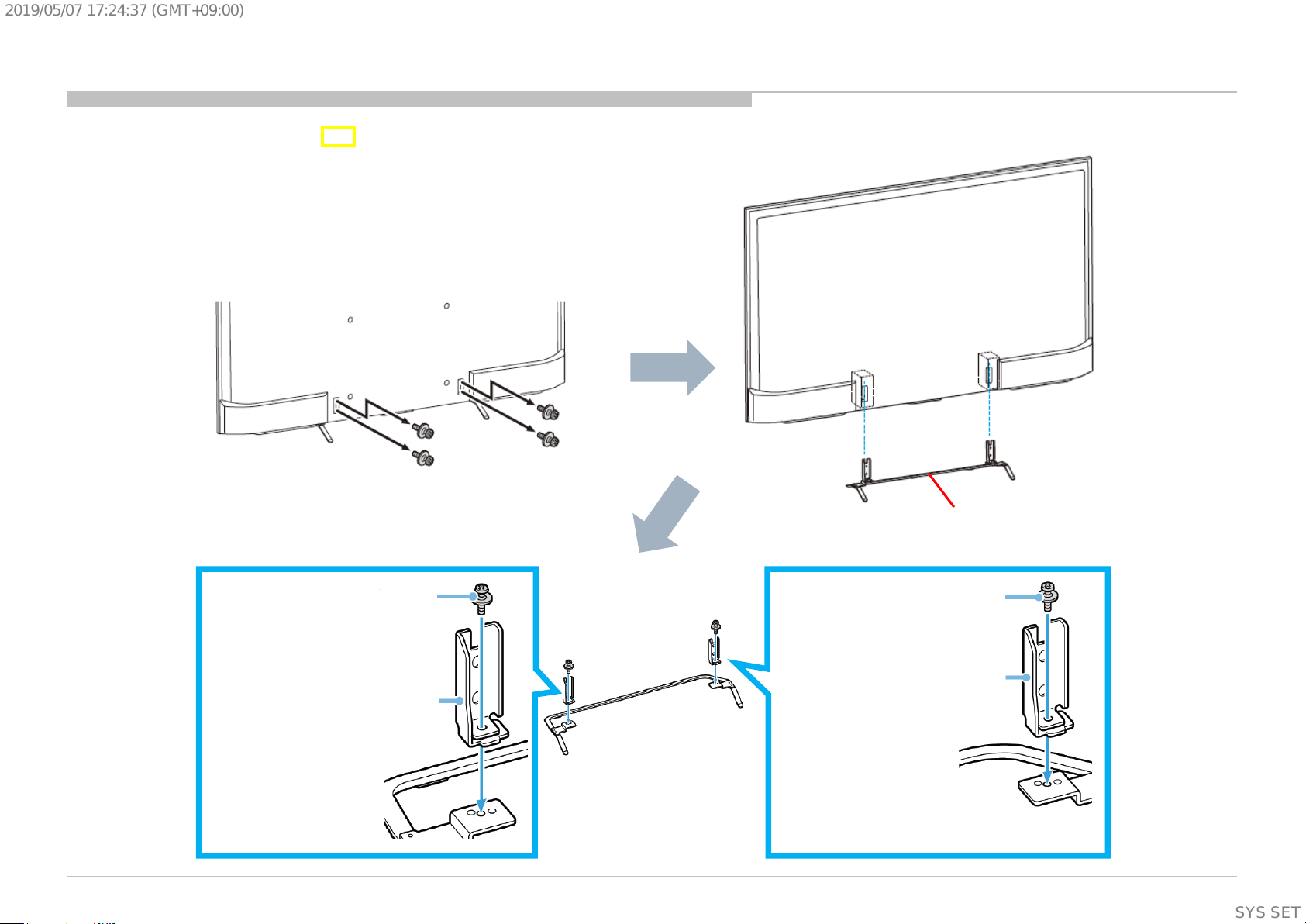
1-3. KD-75X8501C (FW-75X8570C)/8505C
1-3-1. STAND SHAFT (3L HWK) A
DISASSEMBLY
4 screws (SCREW, +PSW M6X12) P/N: 4-567-081-01
2 screws (SCREW, +PSW M5X20)
P/N: 4-567-082-01
NECK
KD-55/65/75X8501C (FW-55/65/75X8570C), 8505C, 8507C, 8508C, 8509C
STAND
2 screws (SCREW, +PSW M5X20)
P/N: 4-567-082-01
NECK
75
SYSSET
Page 76

2019/05/0717:24:37(GMT+09:00)
1-3. KD-75X8501C (FW-75X8570C)/8505C
1-3-2. LABEL, UNDER TERMINAL AND LABEL, REAR TERMINAL AND LABEL, SIDE TERMINAL (L) AND LABEL, CI
DISASSEMBLY
LABEL, CI
LABEL, REAR TERMINAL
KD-55/65/75X8501C (FW-55/65/75X8570C), 8505C, 8507C, 8508C, 8509C
LABEL, UNDER TERMINAL
LABEL, SIDE TERMINAL (L)
76
SYSSET
Page 77

2019/05/0717:24:37(GMT+09:00)
1-3. KD-75X8501C (FW-75X8570C)/8505C
1-3-3. AC COVER AND POWER SUPPLY CORD
DISASSEMBLY
1
2 3 4
KD-55/65/75X8501C (FW-55/65/75X8570C), 8505C, 8507C, 8508C, 8509C
POWER SUPPLY CORD
AC COVER
Screw (SCREW +PSW M4X10) P/N: 4-159-298-01
5
77
SYSSET
Page 78
2019/05/0717:24:37(GMT+09:00)
1-3. KD-75X8501C (FW-75X8570C)/8505C
1-3-4. UNDER COVER (3L_HWK) A
2
DISASSEMBLY
1
13 screws (SCREW , +PWH M3X6) P/N: 4-452-935-11
4 screws (SCREW, ORNAMENTAL M6X12) P/N: 4-268-126-02
10 screws (SCREW, +BVTP 4X12 TYPE2 IT-3) P/N: 2-580-639-01
KD-55/65/75X8501C (FW-55/65/75X8570C), 8505C, 8507C, 8508C, 8509C
3
UNDER COVER (3L_HWK) A
78
SYSSET
Page 79

2019/05/0717:24:37(GMT+09:00)
1-3. KD-75X8501C (FW-75X8570C)/8505C
1-3-5. TAPE
TAPE
DISASSEMBLY
TAPE
KD-55/65/75X8501C (FW-55/65/75X8570C), 8505C, 8507C, 8508C, 8509C
TAPE
TAPE
TAPE
79
SYSSET
Page 80

2019/05/0717:24:37(GMT+09:00)
1-3. KD-75X8501C (FW-75X8570C)/8505C
1-3-6. TAPE
DISASSEMBLY
TAPE
TAPE
TAPE
KD-55/65/75X8501C (FW-55/65/75X8570C), 8505C, 8507C, 8508C, 8509C
TAPE
80
SYSSET
Page 81

2019/05/0717:24:37(GMT+09:00)
1-3. KD-75X8501C (FW-75X8570C)/8505C
1-3-7. WIRE DRESSING
DISASSEMBLY
KD-55/65/75X8501C (FW-55/65/75X8570C), 8505C, 8507C, 8508C, 8509C
81
SYSSET
Page 82

2019/05/0717:24:37(GMT+09:00)
1-3. KD-75X8501C (FW-75X8570C)/8505C
1-3-8. SPEAKER BOX ASSY (L)
DISASSEMBLY
1
2 3
KD-55/65/75X8501C (FW-55/65/75X8570C), 8505C, 8507C, 8508C, 8509C
SPEAKER BOX ASSY (L)
82
SYSSET
Page 83

2019/05/0717:24:37(GMT+09:00)
1-3. KD-75X8501C (FW-75X8570C)/8505C
1-3-9. BRACKET, SP (2L HWK) A
DISASSEMBLY
1
4 screws (SCREW , +PSW M3X8) P/N: 2-580-593-01
2 3
KD-55/65/75X8501C (FW-55/65/75X8570C), 8505C, 8507C, 8508C, 8509C
BRACKET, SP (2L HWK) A
83
SYSSET
Page 84

2019/05/0717:24:37(GMT+09:00)
1-3. KD-75X8501C (FW-75X8570C)/8505C
1-3-10. SPEAKER BOX ASSY (R)
DISASSEMBLY
1
2 3
KD-55/65/75X8501C (FW-55/65/75X8570C), 8505C, 8507C, 8508C, 8509C
SPEAKER BOX ASSY (R)
84
SYSSET
Page 85

2019/05/0717:24:37(GMT+09:00)
1-3. KD-75X8501C (FW-75X8570C)/8505C
1-3-11. BRACKET, SP (2L HWK) A
DISASSEMBLY
1
4 screws (SCREW , +PSW M3X8) P/N: 2-580-593-01
2 3
KD-55/65/75X8501C (FW-55/65/75X8570C), 8505C, 8507C, 8508C, 8509C
BRACKET, SP (2L HWK) A
85
SYSSET
Page 86

2019/05/0717:24:37(GMT+09:00)
1-3. KD-75X8501C (FW-75X8570C)/8505C
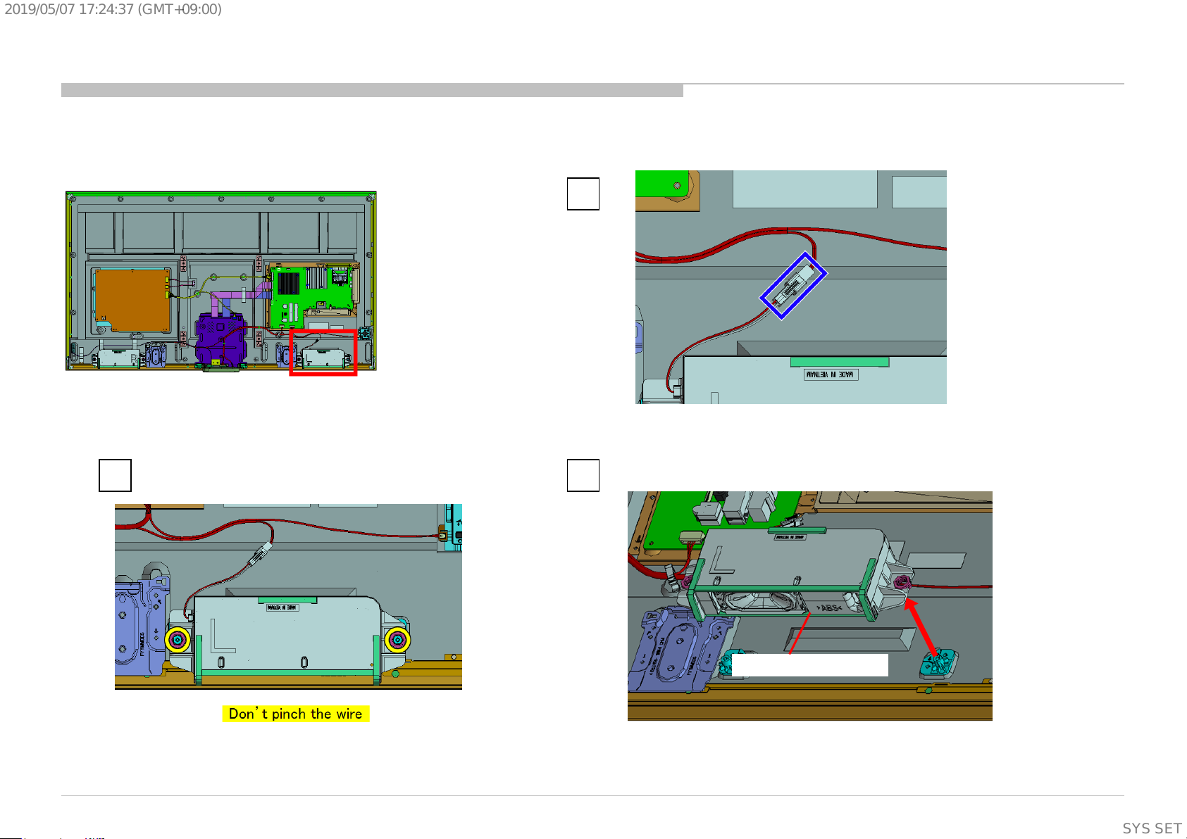
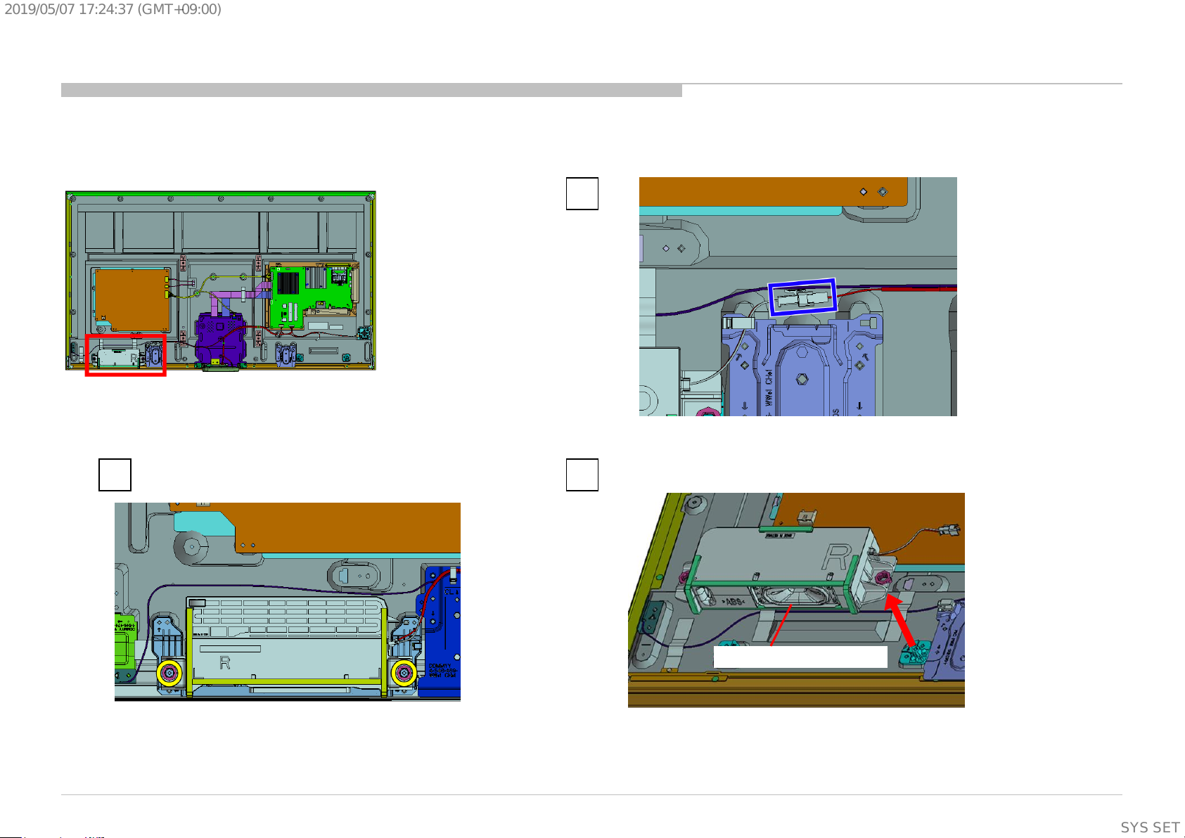
1-3-12. BRACKET,BT (EGL) ASSY
DISASSEMBLY
1
2
Screw (SCREW (+PSW)(M3X6))
P/N: 2-990-421-41
KD-55/65/75X8501C (FW-55/65/75X8570C), 8505C, 8507C, 8508C, 8509C
3 4 5
BRACKET,BT (EGL) ASSY
86
SYSSET
Page 87

2019/05/0717:24:37(GMT+09:00)
1-3. KD-75X8501C (FW-75X8570C)/8505C
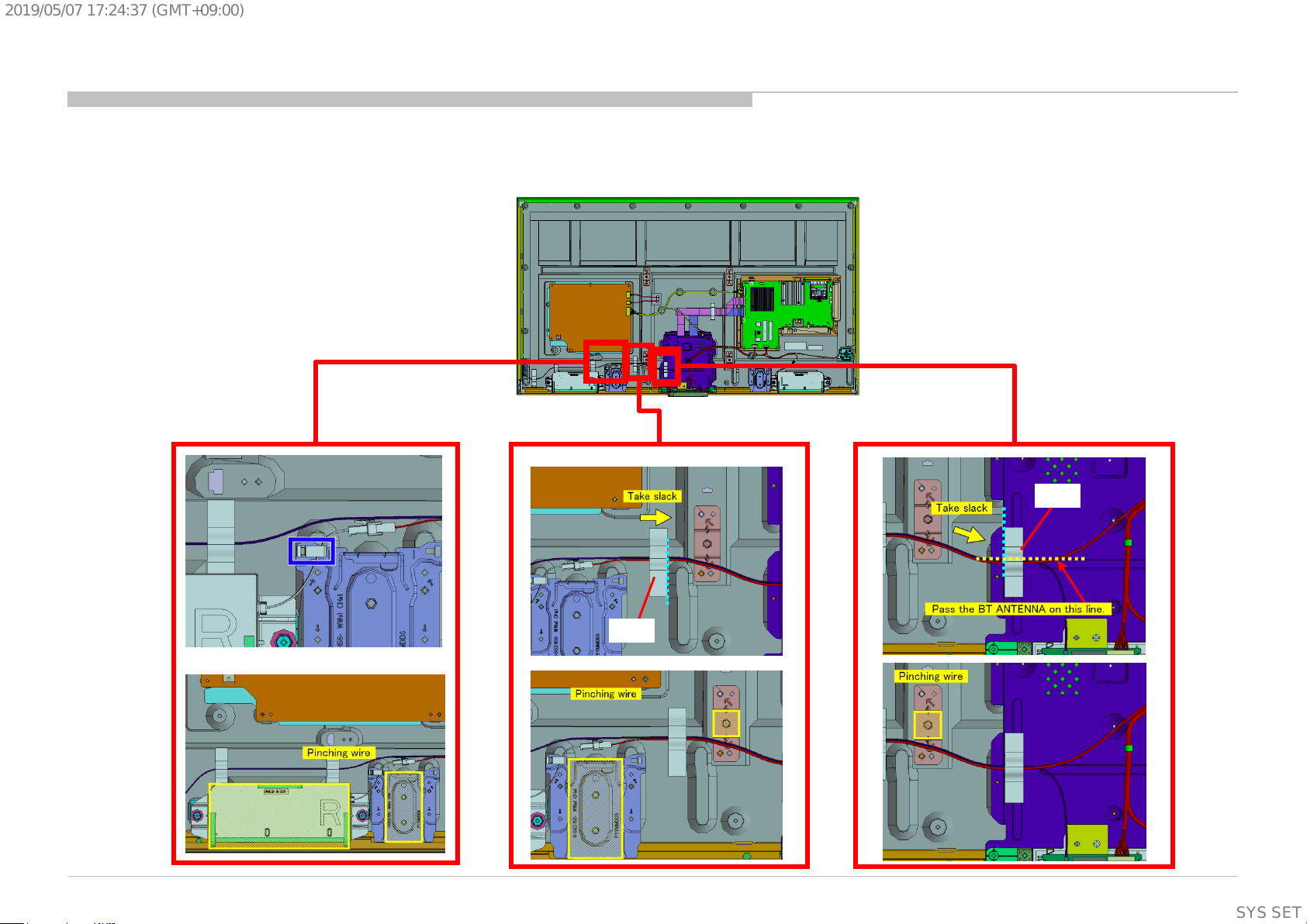
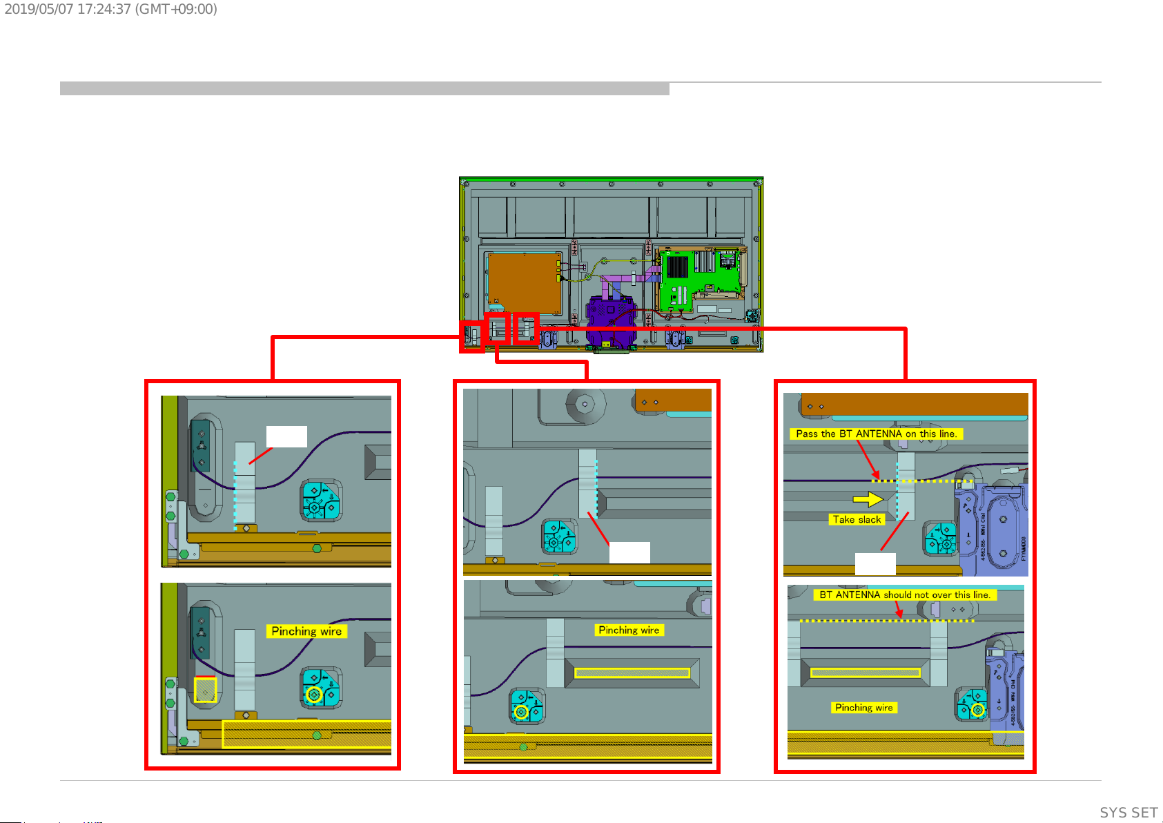
1-3-13. BT ANTENNA AND BRACKET, BT(EGL)
DISASSEMBLY
1 2
Screw (SCREW (+PSW)(M3X6))
P/N: 2-990-421-41
3 4
KD-55/65/75X8501C (FW-55/65/75X8570C), 8505C, 8507C, 8508C, 8509C
BT ANTENNA
BRACKET,BT (EGL)
87
SYSSET
Page 88

2019/05/0717:24:37(GMT+09:00)
1-3. KD-75X8501C (FW-75X8570C)/8505C
1-3-14. SMART CORE
DISASSEMBLY
Notes on assembling the Smart core
1 2
SMART CORE
KD-55/65/75X8501C (FW-55/65/75X8570C), 8505C, 8507C, 8508C, 8509C
88
SYSSET
Page 89

2019/05/0717:24:37(GMT+09:00)
1-3. KD-75X8501C (FW-75X8570C)/8505C
1-3-15. SWITCH UNIT
DISASSEMBLY
1
Release the lock
2 3
KD-55/65/75X8501C (FW-55/65/75X8570C), 8505C, 8507C, 8508C, 8509C
SWITCH UNIT
89
SYSSET
Page 90

2019/05/0717:24:37(GMT+09:00)
1-3. KD-75X8501C (FW-75X8570C)/8505C
1-3-16. HARNESS ASSY (GBT / MAIN) AND CONNECTOR ASSY, 3P AND CONNECTOR ASSY 9P
DISASSEMBLY
CONNECTOR ASSY 9P
P/N: 1-910-109-98
CONNECTOR ASSY, 3P
P/N: 1-848-869-11
HARNESS ASSY (GBT / MAIN)
P/N: 1-910-109-97
KD-55/65/75X8501C (FW-55/65/75X8570C), 8505C, 8507C, 8508C, 8509C
90
SYSSET
Page 91

2019/05/0717:24:37(GMT+09:00)
1-3. KD-75X8501C (FW-75X8570C)/8505C
1-3-17. BRACKET,VESA(HWK)
DISASSEMBLY
1
2 3
KD-55/65/75X8501C (FW-55/65/75X8570C), 8505C, 8507C, 8508C, 8509C
8 screws (SCREW, +PSW M4X8) P/N: 2-580-600-11
BRACKET,VESA(HWK)
91
SYSSET
Page 92

2019/05/0717:24:37(GMT+09:00)
1-3. KD-75X8501C (FW-75X8570C)/8505C
1-3-18. BRACKET, SC(HWK)
DISASSEMBLY
1
4 screws (SCREW, +PSW M3X8) P/N: 2-580-593-01
KD-55/65/75X8501C (FW-55/65/75X8570C), 8505C, 8507C, 8508C, 8509C
3 2
BRACKET,SC(HWK)
92
SYSSET
Page 93
2019/05/0717:24:37(GMT+09:00)
1-3. KD-75X8501C (FW-75X8570C)/8505C
1-3-19. SLIDE, CLAMP
DISASSEMBLY
1
2
SLIDE, CLAMP
1
2
SLIDE, CLAMP
KD-55/65/75X8501C (FW-55/65/75X8570C), 8505C, 8507C, 8508C, 8509C
93
SYSSET
Page 94

2019/05/0717:24:37(GMT+09:00)
1-3. KD-75X8501C (FW-75X8570C)/8505C
1-3-20. BRACKET, STD C (2L_HWK)
DISASSEMBLY
1
2
4 screws (SCREW, +PSW M4X8) P/N: 2-580-600-11
3
BRACKET, STD C(2L_HWK)
1
Screw (PULLEY, STAND (HWI)) P/N: 4-534-964-01 Screw (PULLEY, STAND (HWI)) P/N: 4-534-964-01
2
4 screws (SCREW, +PSW M4X8) P/N: 2-580-600-11
3
BRACKET, STD C(2L_HWK)
KD-55/65/75X8501C (FW-55/65/75X8570C), 8505C, 8507C, 8508C, 8509C
94
SYSSET
Page 95

2019/05/0717:24:37(GMT+09:00)
1-3. KD-75X8501C (FW-75X8570C)/8505C
1-3-21. G4-STATIC CONVERTER(TV)
DISASSEMBLY
2
4 screws (SCREW, +PSW M3X6 W12) P/N: 4-256-393-11
KD-55/65/75X8501C (FW-55/65/75X8570C), 8505C, 8507C, 8508C, 8509C
3 1
G4
95
SYSSET
Page 96

2019/05/0717:24:37(GMT+09:00)
1-3. KD-75X8501C (FW-75X8570C)/8505C
1-3-22. SHEET, INSULATION(HWK 3L SYS)
(An insulation sheet is under the G4 power supply board.)
1 2
DISASSEMBLY
SHEET, INSULATION(HWK 3L SYS)
KD-55/65/75X8501C (FW-55/65/75X8570C), 8505C, 8507C, 8508C, 8509C
96
SYSSET
Page 97

2019/05/0717:24:37(GMT+09:00)
1-3. KD-75X8501C (FW-75X8570C)/8505C
1-3-23. GL2-STATIC CONVERTER(TV)
DISASSEMBLY
2
7 screws (SCREW, +PSW M3X6 W12) P/N: 4-256-393-11
KD-55/65/75X8501C (FW-55/65/75X8570C), 8505C, 8507C, 8508C, 8509C
3 1
GL2
97
SYSSET
Page 98

2019/05/0717:24:37(GMT+09:00)
1-3. KD-75X8501C (FW-75X8570C)/8505C
1-3-24. SHEET, INSULATION(HWK 3L)
(An insulation sheet is under the GL2 power supply board.)
1 2
DISASSEMBLY
SHEET, INSULATION(HWK 3L)
KD-55/65/75X8501C (FW-55/65/75X8570C), 8505C, 8507C, 8508C, 8509C
98
SYSSET
Page 99

2019/05/0717:24:37(GMT+09:00)
1-3. KD-75X8501C (FW-75X8570C)/8505C
1-3-25. TAPE, FFC (HWK 3L)
DISASSEMBLY
TAPE, FFC (HWK 3L)
KD-55/65/75X8501C (FW-55/65/75X8570C), 8505C, 8507C, 8508C, 8509C
99
SYSSET
Page 100

2019/05/0717:24:37(GMT+09:00)
1-3. KD-75X8501C (FW-75X8570C)/8505C
1-3-26. FLEXIBLE FLAT CABLE 41P AND FLEXIBLE FLAT CABLE 51P
DISASSEMBLY
1
TAPE
2 3
KD-55/65/75X8501C (FW-55/65/75X8570C), 8505C, 8507C, 8508C, 8509C
FLEXIBLE FLAT CABLE 41P
P/N: 1-848-890-11
FLEXIBLE FLAT CABLE 51P
P/N: 1-848-891-11
100
SYSSET
 Loading...