

SONY KD-34XS955, KD-36XS955 Service Manual

HISTORY INFORMATION FOR THE FOLLOWING MANUAL:
SERVICE MANUAL
MODEL NAME REMOTE COMMANDER DESTINATION CHASSIS NO.
KD-30XS955
KD-30XS955
KD-34XBR960
KD-34XBR960
KD-34XS955
KD-34XS955
KD-34XS955
KD-36XS955
KD-36XS955
RM-Y199 US SCC-S66U-A
RM-Y199 HAWAII SCC-S69K-A
RM-Y201 US SCC-S66V-A
RM-Y201 HAWAII SCC-S69L-A
RM-Y199 US SCC-S66W-A
RM-Y199 CANADA SCC-S70V-A
RM-Y199 HAWAII SCC-S69M-A
RM-Y199 US SCC-S66X-A
RM-Y199 HAWAII SCC-S69N-A
DA-4
CHASSIS
ORIGINAL MANUAL ISSUE DATE: 6/2004
:UPDATED ITEM
☛
REVISION DATE SUBJECT
6/2004 No revisions or updates are applicable at this time.
7/2004 Reissue entire manual
11/2004 Updated Table of Contents (Replace Pg. 3 with Pg. 3)
Added Note to Cable Wire Dressing section (Replace Pg. 13 with Page 13)
Updated 2-1. Beam Landing instructions (Replace Pg. 34 with Pg. 34)
Updated ID Map Table (Replace Pg. 92 with Pg. 92)
Updated Circuit Boards Location diagram (Replace Pg. 93 with Pg. 93)
Replaced P Board Schematic Diagram (Replace Pg. 99 with Pg. 99)
Added PA Board Schematic and PWBs (Add Pgs. 100-A and 100-B)
Updated BY Board PWBs (Replace Pgs. 111 & 112 with Pgs. 111 &112)
Updated DZ Board Schematic (2 of 2) (Replace Pg. 123 with Pg. 123)
Added PA Board to Exploded View section (Replace Pgs. 141, 143, & 145 with Pgs. 141, 143, & 145)
Added PA Board information to Electrical Parts Lists (Add Pgs. 204-208)
12/2004 Corrected Self-Diagnostic Circuit Diagram (Replace Pg. 9 with Pg. 9)
2/2005 Updated 2-1. Beam Landing instructions (Replace Pg. 34 with Pg. 34)
Reorganized 2-2. Convergence and 2-3. V-Pin and V-Cen Adjusment instructions
(Replace Pg. 35 with Pg. 35)
Corrected Block Diagram (Replace Pg. 94 with Pg. 94)
Updated DZ Schematic Diagram to correct IC5005 pin 3 (Replace Pg. 122 with Pg. 122)
Corrected Exploded View diagrams to show correct placement of Neck Assembly & Landing Coil Correction
Corrected PN for Control Door & Power Button, Added Door Damper
(Replace Pgs. 142, 144, &146 with Pgs. 142, 144, &146)
9-965-965-05
TRINITRON® COLOR TELEVISION
Self Diagnosis
Supported model
SERVICE MANUAL
MODEL NAME REMOTE COMMANDER DESTINATION CHASSIS NO.
KD-30XS955
KD-30XS955
KD-34XBR960
KD-34XBR960
KD-34XS955
KD-34XS955
KD-34XS955
KD-36XS955
KD-36XS955
RM-Y199 US SCC-S66U-A
RM-Y199 HAWAII SCC-S69K-A
RM-Y201 US SCC-S66V-A
RM-Y201 HAWAII SCC-S69L-A
RM-Y199 US SCC-S66W-A
RM-Y199 CANADA SCC-S70V-A
RM-Y199 HAWAII SCC-S69M-A
RM-Y199 US SCC-S66X-A
RM-Y199 HAWAII SCC-S69N-A
DA-4
CHASSIS
9-965-965-05
KD-34XBR960 RM-201
TRINITRON® COLOR TELEVISION

KD-30XS955/34XBR960/34XS955/36XS955
TABLE OF CONTENTS
SECTION TITLE PAGE SECTION TITLE PAGE
Specifications ................................................................................. 4
Warnings and Cautions .................................................................. 6
Safety Check-Out ........................................................................... 7
Self-Diagnostic Function ................................................................. 8
SECTION 1: DISASSEMBLY ................................................................11
1-1. Rear Cover Removal .............................................................11
1-2. Chassis Assembly Removal ..................................................11
1-3. Service Position ....................................................................11
1-4. Picture Tube Removal .......................................................... 12
Anode Cap Removal Procedure .......................................... 12
Cable Wire Dressing ............................................................ 13
SECTION 2: SET-UP ADJUSTMENTS ................................................ 34
2-1. Beam Landing ...................................................................... 34
2-2. Convergence ........................................................................ 35
2-2.1. Vertical and Horizontal Static Convergence ............ 35
2-3. V-PIN and V-CEN Adjustment .............................................. 35
2-3.1. Operation of BMC (Hexapole) Magnet .................... 35
2-3.2. TLH Plate Adjustment .............................................. 36
2-3.3. Screen-Corner Convergence ................................... 36
2-3.4. Dynamic Convergence Adjustments ........................ 36
2-4. Focus Adjustment ................................................................. 37
2-4.1. Dynamic Focus/Dynamic Quadra-Pole Data ........... 37
2-5. Screen (G2) .......................................................................... 38
2-6. Picture Quality Adjustments ................................................. 38
2-6.1. Video Input - Sub Contrast Adjustment .................... 38
2-6.2. Video Input - Sub Hue/Sub Color Adjustment .......... 39
2-6.3. RF Input - Sub Contrast Adjustment ........................ 39
2-6.4. RF Input - Sub Hue/Sub Color Adjustment .............. 40
2-7. White Balance (CRT) and Sub Bright Adjustment ................ 40
2-7.1. Color Offset Adjustment Procedure ......................... 41
2-8. H Raster Center Adjustment ................................................ 41
2-9. Picture Distortion Adjustments ............................................. 42
2-9.1. NTSC (DRC) Full Mode Adjustment ........................ 42
2-9.2. 1080i HD Mode Adjustment ..................................... 43
2-9.3. Vertical Compressed Mode Check and Confirmation
(For 4x3 CRT Only) ................................................. 43
2-9.4. Normal, Zoom and Wide Zoom modes .................... 43
SECTION 3: SAFETY RELATED ADJUSTMENTS ............................. 44
3-1. Preparation Before Confirmation .......................................... 44
3-1.1 Hold-Down Operation Confirmation ......................... 44
3-2. B+ Max Confirmation ........................................................... 44
3-3. B+ Voltage Check ................................................................ 44
3-4. High Voltage (HV) Check ..................................................... 44
3-5. Preparation for HV and IK Protector Check ......................... 44
3-6. HV Protector Check ............................................................. 44
3-6-1. Cut Off Condition ..................................................... 44
3-6-2. High Light Condition ................................................ 45
3-7. IK Protector Check ............................................................... 45
3-8. Hold Down Check ................................................................ 45
3-9. Restoration ........................................................................... 45
3-10. HS Service Flowchart ........................................................... 46
HS Service Flowchart Table ................................................. 47
SECTION 4: CIRCUIT ADJUSTMENTS .............................................. 48
4-1. Setting Service Adjustment Mode ........................................ 48
4-1.1. Service Adjustment Mode In .................................... 48
4-1.2. Service Adjustment Mode Memory .......................... 48
4-1.3. Reading the Memory ............................................... 48
4-1.4. Adjusting the Picture ................................................ 48
4-1.5. Resetting the Data ................................................... 48
4-1.6. Resetting the MID NVM Data .................................. 48
4-1.7. Resetting the System NVM Data ............................. 48
4-1.8. Copy Function .......................................................... 48
4-2. Memory Write Confirmation Method .................................... 49
4-3. Remote Adjustment Buttons and Indicators ......................... 49
4-4. Service Data ......................................................................... 50
KD-34XBR960 Service Data Only ........................................ 50
KD-30XS955/34XS955/36XS955 Service Data Only ........... 71
4-5. ID Map Table ........................................................................ 92
SECTION 5: DIAGRAMS ..................................................................... 93
5-1. Circuit Boards Location ........................................................ 93
5-2. Printed Wiring Boards and
Schematic Diagrams Information ......................................... 93
5-3. Block Diagrams .................................................................... 94
5-4. Schematics and Supporting information .............................. 97
DL Board Schematic Diagram .............................................. 97
P Board Schematic Diagram ................................................ 99
PA Board Schematic Diagram ......................................... 100-A
AZ Board Schematic Diagram (1 of 3) ............................... 101
AZ Board Schematic Diagram (2 of 3) ............................... 102
AZ Board Schematic Diagram (3 of 3) ............................... 103
BY Board Schematic Diagram (1 of 5) ............................... 106
BY Board Schematic Diagram (2 of 5) ............................... 107
BY Board Schematic Diagram (3 of 5) ............................... 108
BY Board Schematic Diagram (4 of 5) ............................... 109
BY Board Schematic Diagram (5 of 5) ................................ 110
MZ Board Schematic Diagram (1 of 4) ................................113
MZ Board Schematic Diagram (2 of 4) ................................114
MZ Board Schematic Diagram (3 of 4) ................................115
MZ Board Schematic Diagram (4 of 4) ................................116
UZ Board Schematic Diagram ............................................119
DZ Board Schematic Diagram (1 of 2) ............................... 122
DZ Board Schematic Diagram (2 of 2) ............................... 123
HCX Board Schematic Diagram ......................................... 127
CX Board Schematic Diagram ........................................... 129
HAX Board Schematic Diagram ......................................... 132
HBZ Board Schematic Diagram ......................................... 134
WY Board Schematic Diagram .......................................... 136
5-5. Semiconductors (1 of 2) ..................................................... 139
Semiconductors (2 of 2) ..................................................... 140
SECTION 6: EXPLODED VIEWS ...................................................... 141
6-1. Chassis (KD-34XBR960 Only) ........................................... 141
6-2. Picture Tube (KD-34XBR960 Only) .................................... 142
6-3. Chassis (KD-30XS955/34XS955 Only) .............................. 143
6-4. Picture Tube (KD-30XS955/34XS955 Only) ...................... 144
6-5. Chassis (KD-36XS955 Only) .............................................. 145
6-6. Picture Tube (KD-36XS955 Only) ...................................... 146
KD-30XS955/34XBR960/34XS955/36XS955
SECTION 7: ELECTRICAL PARTS LIST ......................................... 147
3
SPECIFICATIONS
KD-30XS955/34XBR960/34XS955/36XS955
Power Requirements
Inputs/Outputs
120V AC, 60Hz
HDMI IN
Video
1080i, 720p, 480p, 480i
Audio Two channel linear PCM 32, 44.1 and 48 kHz,
16, 20, and 24 bit
Video (IN)
4 total (1 on front panel)
1Vp-p, 75ohms unbalanced, sync negative
S Video (IN)
3 total (1 on front panel)
Y: 1Vp-p, 75ohms unbalanced, sync negative
C: 0.286Vp-p (Burst signal), 75ohms
Audio (IN)
7 total (1 on front panel)
500 mVrms (100% modulation)
Impedance:47 kilo ohms
Control S (IN/OUT)
1 total
Component Video Input
2 (Y, PB, PR)
Y: 1.0 Vp-p, 75 ohms unbalanced, sync negative
: 0.7 Vp-p, 75 ohms;
P
B
PR: 0.7 Vp-p, 75 ohms
Audio OUT (VAR/FIX)
1 total
At the maximum volume setting
More than 408 mVrms (Variable)
More than 408 mVrms (Fixed)
Impedance (Output):2 kilo ohm
i.LINK (KD-34XBR960 Only)
3 total (1 on front panel)
4-pin S400 i.LINK terminal
Digital Audio Optical Output
PCM/Dolby Digital
1 total
Optical Rectangular
CableCARD Slot
PCMCIA Type I/II
KD-30XS955 KD-34XBR960 KD-34XS955 KD-36XS955
Speaker Output (W)
Power Consumption (W)
In Use (Max) 220 W 270 W 250 W 270 W
In Standby 3 W 3 W 3 W 3 W
In CableCARD Standby 20 W 23 W 20 W 20 W
Dimensions (W x H x D)
mm 898 x 604 x 564.5 mm 994 x 652 x 605 mm 994 x 654 x 604 mm 994 x 776.5 x 634 mm
3/8
3/4
35
in
x 23
x 22
1/4
in 39
Mass
kg 67 kg 89 kg 93 kg 108.2 kg
lbs 148 lbs 196 lbs 205 lbs 238.5 lbs
© 2004 Dolby Laboratories, Inc.
Dolby, Pro Logic, and the double-D symbol are registered
trademarks of Dolby Laboratories.
TruSurround
by SRS
TruSurround is a trademark of SRS Labs, Inc. SRS and the SRS
symbol are registered trademarks of SRS Labs, Inc. in the United
States and in select foreign countries. SRS and TruSurround are
incorporated under license from SRS Labs, Inc. and are protected
under United States Patent Nos. 4,748,669 and 4,841,572 with
numerous additional issued and pending foreign patents. Purchase of this product does not convey the right to sell recordings
made with the TruSurround technology.
™
®
1/8
x 25
7.5 W x 2
15W Subwoofer
5/8
7/8
x 23
in 39
x 25
x 23
3/4
in 39
1/8
x 30
5/8
x 25 in
1/8
3/4
SRS (SOUND RETRIEVAL SYSTEM)
The SRS (SOUND RETRIEVAL SYSTEM) is manufactured
by Sony Corporation under license from SRS Labs, Inc. It is
covered by U.S. Patent No. 4,748,669. Other U.S. and foreign
patents pending.
The word ‘SRS’ and the SRS symbol are registered trademarks of SRS Labs, Inc. BBE and BBE symbol are trademarks of
BBE Sound, Inc. and are licensed by BBE Sound, Inc. under U.S.
Patent No. 4,638,258 and 4,482,866.
KD-30XS955/34XBR960/34XS955/36XS955
Design and specifi cations are subject to change without notice.
4

Television system
American TV standard, NTSC
ATSC compliant (8 VSB terrestrial)
ATSC compliant 8 VSB terrestrial
QAM on cable ANSI/SCTE 07 2000
Channel coverage
Analog
VHF: 2-13/ UHF: 14-69/ CATV: 1-125
Digital
VHF: 2-13/ UHF: 14-69/ CATV: 1-135
Picture tube
FD Trinitron® tube
Visible screen size
30-inch picture measured diagonally (KD-30XS955 Only)
34-inch picture measured diagonally (KD-34XBR960/34XS955 Only)
36-inch picture measured diagonally (KD-36XS955 Only)
Actual screen size
32-inch measured diagonally (KD-30XS955 Only)
36-inch measured diagonally (KD-34XBR960/34XS955 Only)
38-inch measured diagonally (KD-36XS955 Only)
KD-30XS955/34XBR960/34XS955/36XS955
Antenna
75 ohm external terminal for VHF/UHF
Supplied Accessories
Remote Commander
RM-Y199 (KD-30XS955/34XS955/36XS955 Only)
RM-Y201 (KD-34XBR960 Only)
Two Size AA (R6) Batteries
Optional Accessories
AV Cable: VMC-810/820/830 HG
Audio Cable: RKC-515HG
Component Video Cable: VMC-10/30 HG
ILINK cables: (KD-34XBR960 Only)
VMC-IL4415 (4-pin to 4-pin, 1.5 meters)
VMC-IL4435 (4-pin to 4-pin, 3.5 meters)
TV Stand:
SU-30HX1 (KD-30XS955 Only)
SU-34XBR3 (KD-34XBR960 Only)
SU-34HX1 (KD-34XS955 Only)
SU-36HX1 (KD-36XS955 Only)
KD-30XS955/34XBR960/34XS955/36XS955
5

KD-30XS955/34XBR960/34XS955/36XS955
WARNINGS AND CAUTIONS
CAUTION
Short circuit the anode of the picture tube and the anode cap to the metal chassis, CRT shield, or carbon painted on the CRT, after
removing the anode.
WARNING!!
An isolation transformer should be used during any service to avoid possible shock hazard, because of live chassis. The chassis of
this receiver is directly connected to the ac power line.
! SAFETY-RELATED COMPONENT WARNING!!
Components identifi ed by shading and ! mark on the schematic diagrams, exploded views, and in the parts list are critical for safe
operation. Replace these components with Sony parts whose part numbers appear as shown in this manual or in supplements
published by Sony. Circuit adjustments that are critical for safe operation are identifi ed in this manual. Follow these procedures
whenever critical components are replaced or improper operation is suspected.
ATTENTION!!
Apres avoir deconnecte le cap de l’anode, court-circuiter l’anode du tube cathodique et celui de l’anode du cap au chassis metallique
de l’appareil, ou la couche de carbone peinte sur le tube cathodique ou au blindage du tube cathodique.
Afi n d’eviter tout risque d’electrocution provenant d’un chássis sous tension, un transformateur d’isolement doit etre utilisé lors de tout
dépannage. Le chássis de ce récepteur est directement raccordé à l’alimentation du secteur.
! ATTENTION AUX COMPOSANTS RELATIFS A LA SECURITE!!
Les composants identifi es par une trame et par une marque ! sur les schemas de principe, les vues explosees et les listes de pieces
sont d’une importance critique pour la securite du fonctionnement. Ne les remplacer que par des composants Sony dont le numero
de piece est indique dans le present manuel ou dans des supplements publies par Sony. Les reglages de circuit dont l’importance
est critique pour la securite du fonctionnement sont identifi es dans le present manuel. Suivre ces procedures lors de chaque
remplacement de composants critiques, ou lorsqu’un mauvais fonctionnement suspecte.
KD-30XS955/34XBR960/34XS955/36XS955
6
SAFETY CHECK-OUT
g
KD-30XS955/34XBR960/34XS955/36XS955
After correcting the original service problem, perform the following
safety checks before releasing the set to the customer:
1. Check the area of your repair for unsoldered or poorly soldered
connections. Check the entire board surface for solder splashes and
bridges.
2. Check the interboard wiring to ensure that no wires are “pinched” or
touching high-wattage resistors.
3. Check that all control knobs, shields, covers, ground straps, and
mounting hardware have been replaced. Be absolutely certain that
you have replaced all the insulators.
4. Look for unauthorized replacement parts, particularly transistors,
that were installed during a previous repair. Point them out to the
customer and recommend their replacement.
5. Look for parts which, though functioning, show obvious signs of
deterioration. Point them out to the customer and recommend their
replacement.
6. Check the line cords for cracks and abrasion. Recommend the
replacement of any such line cord to the customer.
7. Check the B+ and HV to see if they are specifi ed values. Make sure
your instruments are accurate; be suspicious of your HV meter if
sets always have low HV.
8. Check the antenna terminals, metal trim, “metallized” knobs, screws,
and all other exposed metal parts for AC leakage. Check leakage as
described below.
Leakage Test
The AC leakage from any exposed metal part to earth ground and from
all exposed metal parts to any exposed metal part having a return to
chassis, must not exceed 0.5 mA (500 microamperes). Leakage current
can be measured by any one of three methods.
1. A commercial leakage tester, such as the Simpson 229 or RCA
WT-540A. Follow the manufacturers’ instructions to use these
instructions.
2. A battery-operated AC milliampmeter. The Data Precision 245 digital
multimeter is suitable for this job.
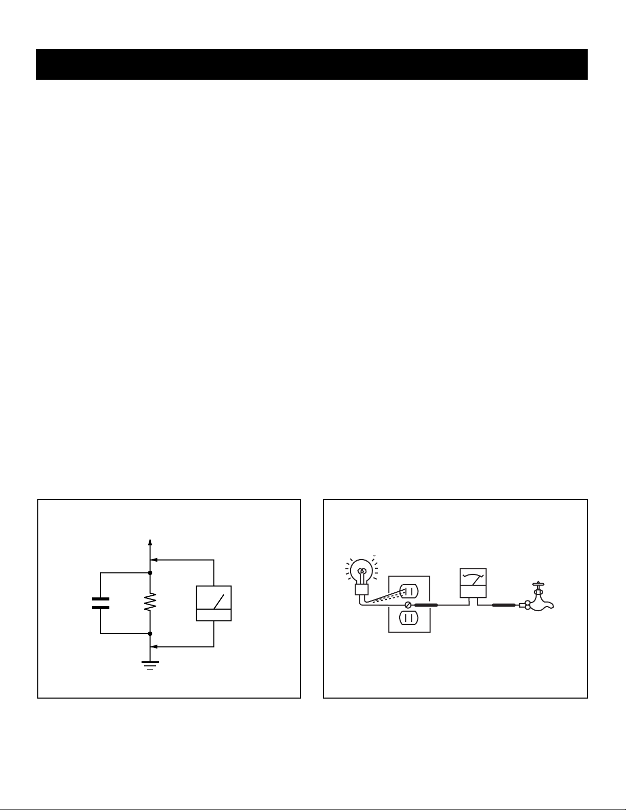
3. Measuring the voltage drop across a resistor by means of a VOM
or battery-operated AC voltmeter. The “limit” indication is 0.75 V,
so analog meters must have an accurate low voltage scale. The
Simpson’s 250 and Sanwa SH-63TRD are examples of passive
VOMs that are suitable. Nearly all battery-operated digital multimeters
that have a 2 VAC range are suitable (see Figure A).
How to Find a Good Earth Ground
A cold-water pipe is a guaranteed earth ground; the cover-plate retaining
screw on most AC outlet boxes is also at earth ground. If the retaining
screw is to be used as your earth ground, verify that it is at ground by
measuring the resistance between it and a cold-water pipe with an
ohmmeter. The reading should be zero ohms.
If a cold-water pipe is not accessible, connect a 60- to 100-watt troublelight (not a neon lamp) between the hot side of the receptacle and the
retaining screw. Try both slots, if necessary, to locate the hot side on the
line; the lamp should light at normal brilliance if the screw is at ground
potential (see Figure B).
To Exposed Metal
Parts on Set
0.15
µ
F
Figure A. Using an AC voltmeter to check AC leakage. Figure B. Checking for earth ground.
kΩ
1.5
Earth Ground
KD-30XS955/34XBR960/34XS955/36XS955
AC V oltmeter
(0.75 V)
AC Outlet Box
Ohmmeter
Cold-water Pipe
7

KD-30XS955/34XBR960/34XS955/36XS955
SELF-DIAGNOSTIC FUNCTION
Self Diagnosis
Supported model
The units in this manual contain a self-diagnostic function. If an error occurs, the STANDBY/TIMER LED will automatically begin to fl ash. The number
of times the LED fl ashes translates to a probable source of the problem. A defi nition of the STANDBY/TIMER LED fl ash indicators is listed in the
instruction manual for the user’s knowledge and reference. If an error symptom cannot be reproduced, the Remote Commander can be used to review
the failure occurrence data stored in memory to reveal past problems and how often these problems occur.
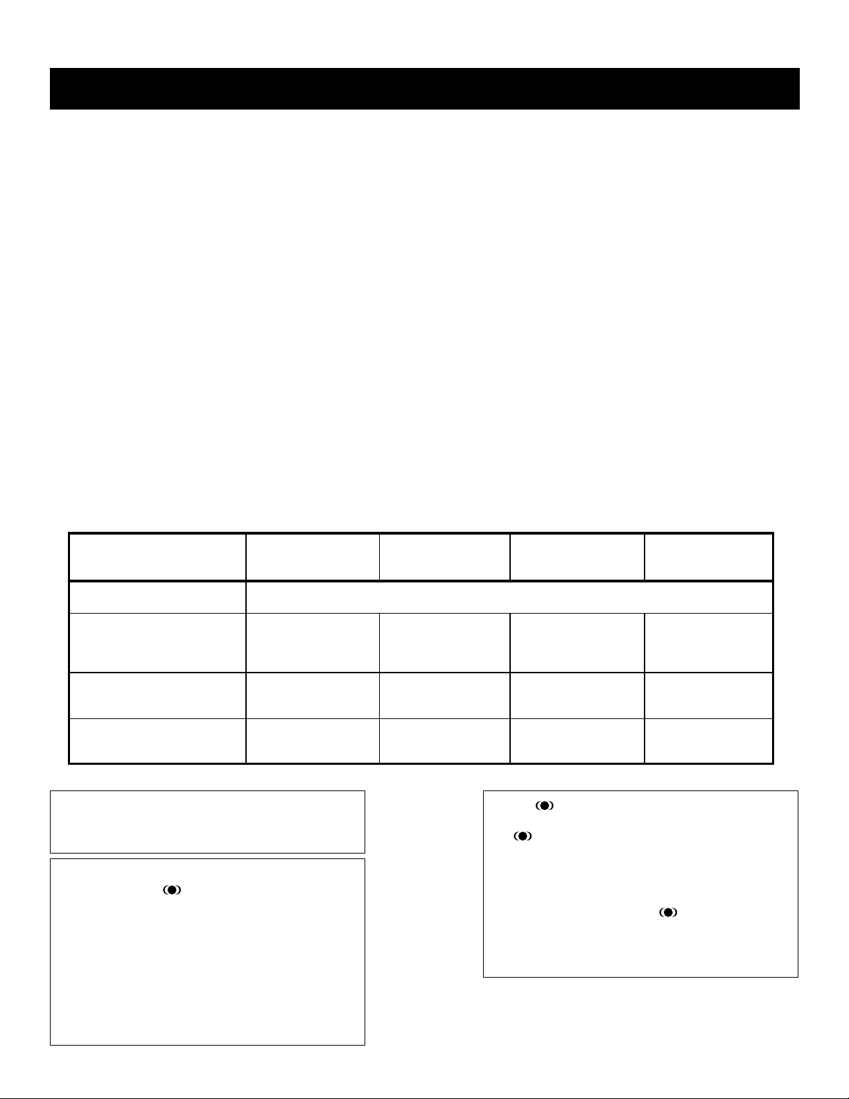
Diagnostic Test Indicators
When an error occurs, the STANDBY/TIMER LED will fl ash a set number of times to indicate the possible cause of the problem. If there is more than
one error, the LED will identify the fi rst of the problem areas.
Results for all of the following diagnostic items are displayed on screen. If the screen displays a “0”, an error has occurred.
No. of times
Diagnostic Item
Power does not turn on Does not light _______
+B Overcurrent (OCP)* 2 times 2:0 or 2:1
Low +B Overvoltage (OVP) 3 times 3:0 or 3:1
Vertical Deflection Stopped 4 times 4:0 or 4:1
White Balance Failure
(not balanced)
LOW +B OCP/OVP
(overcurrent/overvoltage)***
Horizontal Deflection
Stopped
STANDBY /
TIMER lamp
flashes
5 times 5:0 or 5:1
6 times 6:0 or 6:1
7 times 7:0 or 7:1
Display
Result
Probable Cause Location Detected Symptoms
• Power cord is not plugged in.
• Fuse is burned out (F501). (AZ Board)
• H.OUT (Q5030) is shorted. (DZ Board)
• +B PWM (Q5003) is shorted.
(DZ Board)
• IC6505 is faulty. (DZ Board) • Has entered standby mode.
• 15V is not supplied. (DZ Board)
• IC5004 is faulty. (DZ Board)
• Video OUT (IC9001-IC9003) is faulty.
(CX Board)
• CRT drive (IC2801) is faulty.
(BY Board.)
• G2 is improperly adjusted.**
• +5 line is overloaded.
(AZ, BY, MZ Boards)
• +5 line is shorted.
(AZ, BY, MZ Boards.)
• IC504 is faulty. (AZ Board)
• Power does not come on.
• No power is supplied to the TV.
• AC Power supply is faulty.
• Power does not come on.
• Load on power line shorted.
• Has entered standby mode after
Horizontal raster.
• Vertical deflection pulse is stopped.
• Power line is shorted or power
supply is stopped.
• No raster is generated.
• CRT cathode current detection
reference pulse output is small.
• No picture
• No picture
* If a +B overcurrent is detected, stoppage of the vertical deflection is detected simultaneously. The symptom that is diagnosed first by the
microcontroller is displayed on the screen.
** Refer to Screen (G2) in Section 2-5 of this manual.
*** If STANDBY/STEREO LED flashes six (6) times, unplug the unit and wait 10 seconds before performing the adjustment.
Display of Standby/Timer LED Flash Count
Diagnostic items Flash count
+B Overcurrent 2 times
Low +B Overvoltage 3 times
Vert. Deflection Stopped 4 times
White Balance Failure 5 times
Low +B OCP/OVP 6 times
Horiz. Deflection Stopped 7 times
Lamp ON 0.3 sec.
Lamp OFF 0.3 sec.
Lamp OFF 3 sec.
* One fl ash count is not used for
Standby/Timer LED
self-diagnostic.
Stopping the Standby/Timer LED Flash
Turn off the power switch on the TV main unit or unplug the power cord from the outlet to stop the STANDBY/TIMER LAMP from fl ashing.
KD-30XS955/34XBR960/34XS955/36XS955
8
KD-30XS955/34XBR960/34XS955/36XS955
Self-Diagnostic Screen Display
For errors with symptoms such as “power sometimes shuts off” or “screen sometimes goes out” that cannot be confi rmed, it is possible to bring up past
occurrences of failure on the screen for confi rmation.
To Bring Up Screen Test
In standby mode, press buttons on the Remote Commander sequentially, in rapid succession, as shown below:
DISPLAY
Channel
Sound volume
5
-
Power ON.
SELF DIAGNOSIS
2: +B OCP 0
3: +B OVP 0
4: VSTOP 0
5: AKB 1
6: LOWB 0
7: H-STOP 0
Numeral “0”
means that no fault was detected.
Numeral “1”
means a fault was detected one
time only.
101: WDT 24
Handling of Self-Diagnostic Screen Display
Since the diagnostic results displayed on the screen are not automatically cleared, always check the self-diagnostic screen during repairs. When you
have completed the repairs, clear the result display to “0”.
Unless the result display is cleared to “0”, the self-diagnostic function will not be able to detect subsequent faults after completion of the repairs.
Clearing the Result Display
To clear the result display to “0”, press buttons on the Remote Commander sequentially when the diagnostic screen is displayed, as shown below:
NOTE: This will also reset all user functions (including auto programming and picture settings)
Quitting the Self-Diagnostic Screen
To quit the entire self-diagnostic screen, turn off the power switch on the Remote Commander or the main unit.
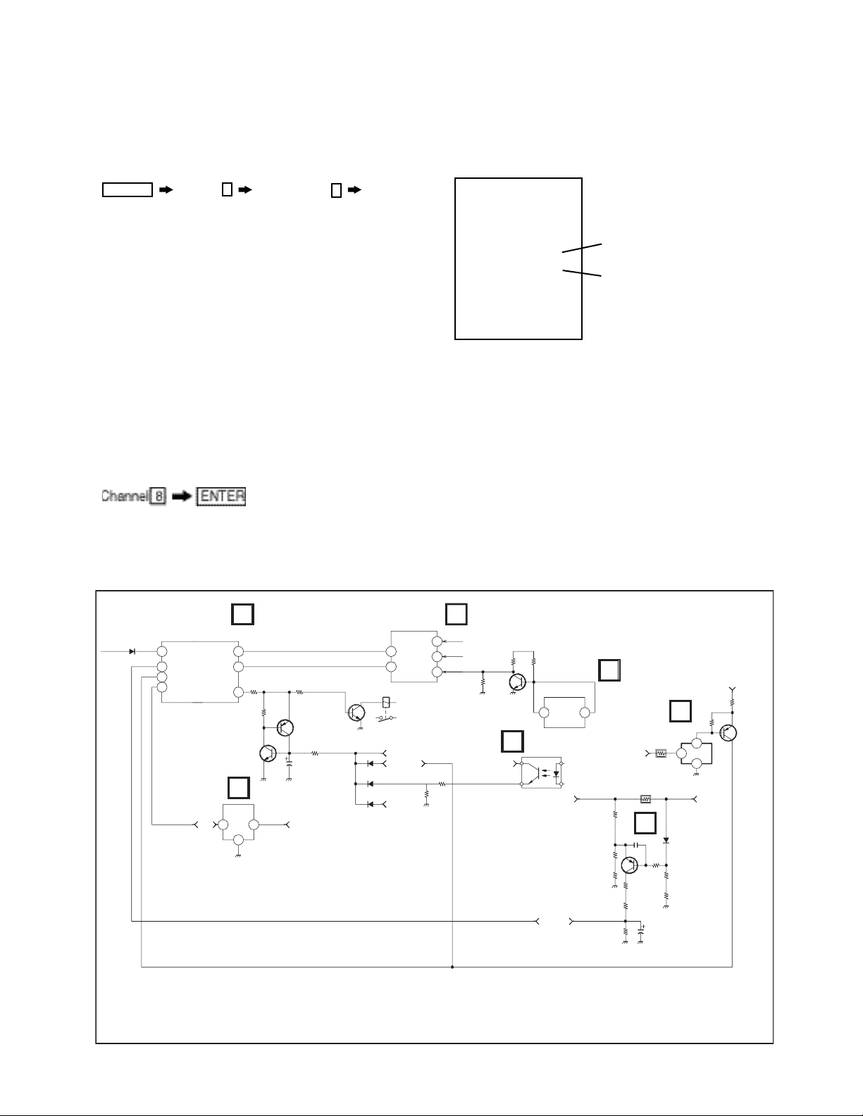
Self-Diagnostic Circuit
☛
STBY-LED
IC2300
MAIN MICRO
STR
48
STBY-LED
44
OCP
OVP
45
43
LOW B ERR
AC RLY
5V UNREG 7V
MZ
CLKO
29
DATO
30
69
Q6527
Q6530
ENABLE ON
LATCH
Q6532
LATCH
AZ
IC504
SV REF
IO
O
IC2801
Y/C JUNGLE
SCL
26
25
SDA
RY6501
P_SW(-)
21
34
1K-PROT2
+B OVP
D6537
D6505
HV PROT
D5007
BY
AKB
VPROT
HPROT
CRT
58
VDY-
35
34
R5104 R5105
R5125
UNREG 11V
BY
Q5018
INVERT
IC5007
2
14
H. PROT
MONITOR
DZ
PH6501
IN RUSH
OVER CURRENT
1
4
2
3
+B +B
Q5004
+ B COP
DETECT
+B OCP
DZ
IC6505
+B OVP
+B
R5013
1
DZ
D5005
5V
Q6522
2
3
FOLLOWER
KD-30XS955/34XBR960/34XS955/36XS955
9

KD-30XS955/34XBR960/34XS955/36XS955
+B overcurrent (OCP)
Occurs when excessive current fl ows through R5013. The increase in voltage across R5013 causes the output of Q5004 to go high, and this high
signal goes to the micro.
+B overvoltage (OVP)
IC6505 detects +B OVP condition and turns on Q6522. This sends a high signal to the micro and also shuts down the AC relay.
V-STOP
Occurs when an absence of the vertical defl ection pulse is detected by pin 24 of IC2801 (BY Board). Power supply will shut down when waveform
interval exceeds 2 seconds.
White Balance Failure
If the RGB levels* do not balance within 2 seconds after the power is turned on, this error will be detected by IC2801. TV will stay on, but there will be
no picture.
*(Refers to the RGB levels of the AKB detection Ref pulse that detects 1K).
Low B OCP/OVP
Occurs when set 5V is out.
Horizontal Defl ection Stopped
Occurs when either:
1) a +B overcurrent is detected (IC5007), or
2) overheating is detected (Thermistor TH5002).
KD-30XS955/34XBR960/34XS955/36XS955
10
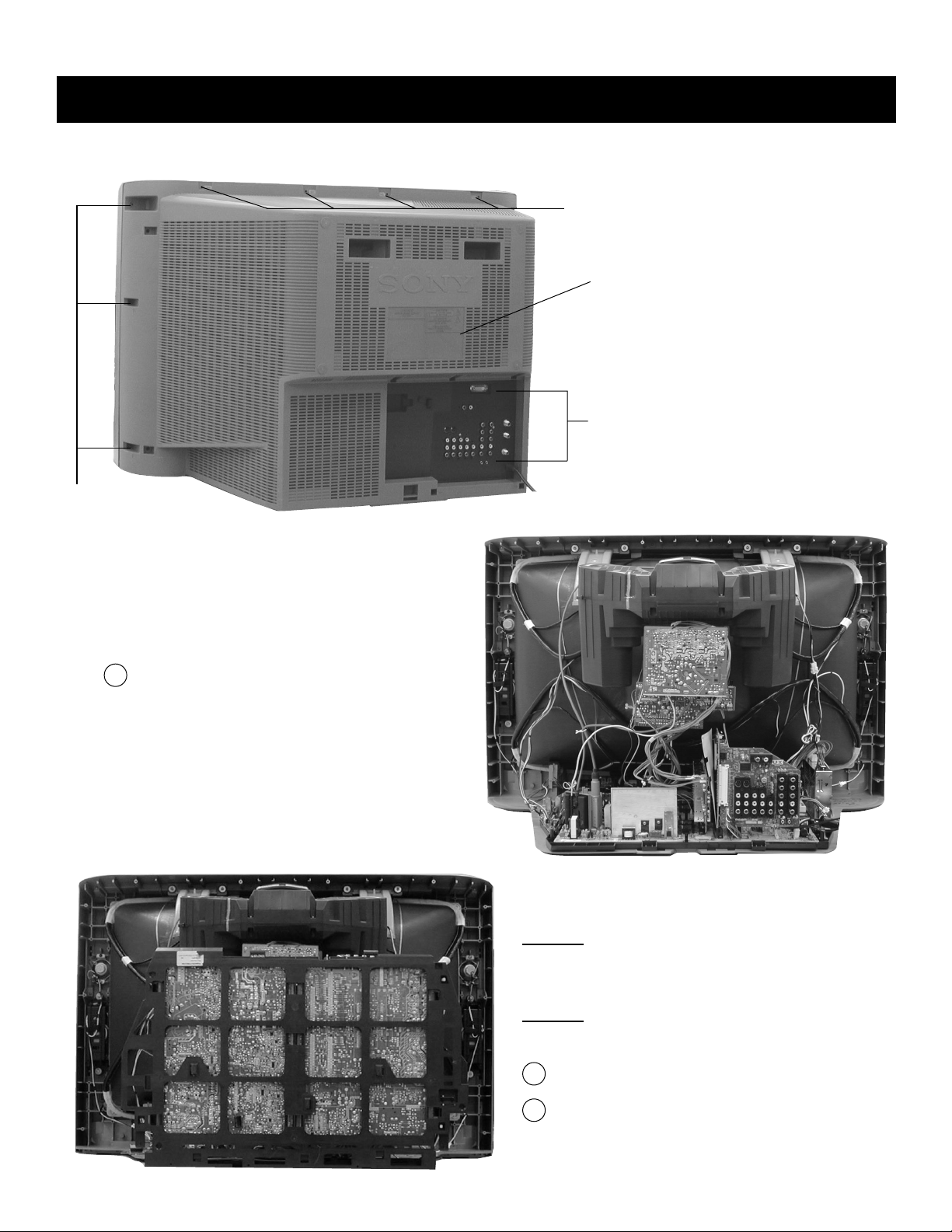
1-1.REAR COVER REMOVAL
KD-30XS955/34XBR960/34XS955/36XS955
SECTION 1: DISASSEMBLY
4 Screws
+BVTP 4 x 16
Rear Cover
5 Screws
+BVTP 4 x 16
3 Screws
+BVTP 4 x 16
1-2.CHASSIS ASSEMBLY REMOVAL
1
Lift lever up on the right and left sides of the chassis
bracket and gently pull the chassis assembly away from
the bezel.
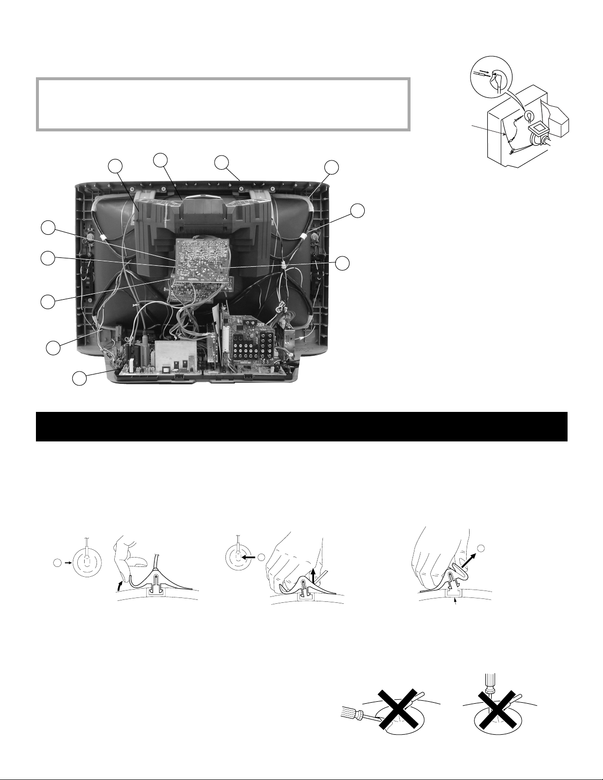
1-3.SERVICE POSITION
CAUTION! - Heat sink on IC5004 is -15V. Do not allow heat sink
to touch GND or any other components.
Heat sink on Q8018 VpK=250V, is -15V. Do not touch or
short to GND or any other components.
CAUTION!
1
2
- Pay attention to Neck Assembly WY Board wire
harness to BY Board. The WY Board can easily break if
there is sudden or excessive tension on the harness.
Lift lever up on the right and left sides of the chassis bracket
and gently pull the chassis assembly away from the bezel.
Pull up and rotate both the AZ and DZ Boards in order to
service the unit.
KD-30XS955/34XBR960/34XS955/36XS955
11
1-4.PICTURE TUBE REMOVAL
WARNING: BEFORE REMOVING THE ANODE CAP
High voltage remains in the CRT even after the power is disconnected. To avoid electric shock,
discharge CRT before attempting to remove the anode cap. Short between anode and CRT
coated earth ground strap.
KD-30XS955/34XBR960/34XS955/36XS955
Coated
Earth
Ground
Strap
1
2
8
11
1. Remove the Sub-Woofer Assemblies.
2. Discharge the anode of the CRT and remove the
anode cap.
9
7
3. Unplug all interconnecting leads from the defl ection
yoke, neck assembly, degaussing coils and CRT
grounding strap.
6
4
4. Remove the CX Board from the CRT.
5. Remove the chassis assembly.
6. Loosen the neck assembly fi xing screw and remove.
7. Loosen the defl ection yoke fi xing screw and remove.
3
8. Place the set with the CRT face down on a cushion
and remove the degaussing coil holders.
9. Remove the degaussing coils.
10
10. Remove the CRT grounding strap and spring tension
devices.
11. Unscrew the four CRT fi xing screws [located on each
5
CRT corner] and remove the CRT
[Take care not to handle the CRT by the neck].
ANODE CAP REMOVAL PROCEDURE
WARNING: High voltage remains in the CRT even after the power is disconnected. To avoid electric shock, discharge CRT before attempting to
remove the anode cap. After removing the anode cap, short circuit to either the metal chassis, CRT shield, or carbon painted on the CRT.
NOTE: After removing the anode cap, short circuit the anode of the picture tube and the anode cap to either the metal chassis, CRT shield or carbon
painted on the CRT.
REMOVAL PROCEDURES
a
Turn up one side of the rubber cap in
the direction indicated by arrow a .
b
Use your thumb to pull the rubber
cap fi rmly in the direction indicated
by arrow b .
HOW TO HANDLE AN ANODE CAP
1. Do not use sharp objects which may cause damage to the surface of the anode
cap.
2. To avoid damaging the anode cap, do not squeeze the rubber covering too
hard. A material fi tting called a shatter-hook terminal is built into the rubber.
3. Do not force turn the foot of the rubber cover. This may cause the shatter-hook
terminal to protrude and damage the rubber.
Anode Button
When one side of the rubber cap separates from
the anode button, the anode cap can be removed
by turning the rubber cap and pulling it in the
direction of arrow c .
c
KD-30XS955/34XBR960/34XS955/36XS955
12
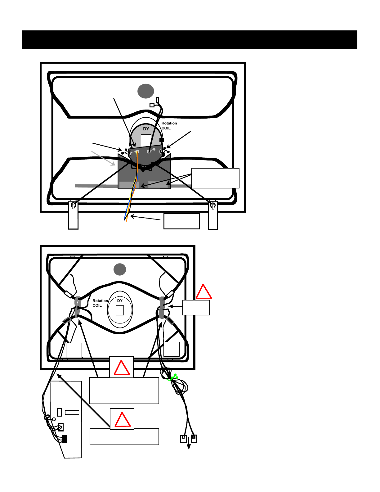
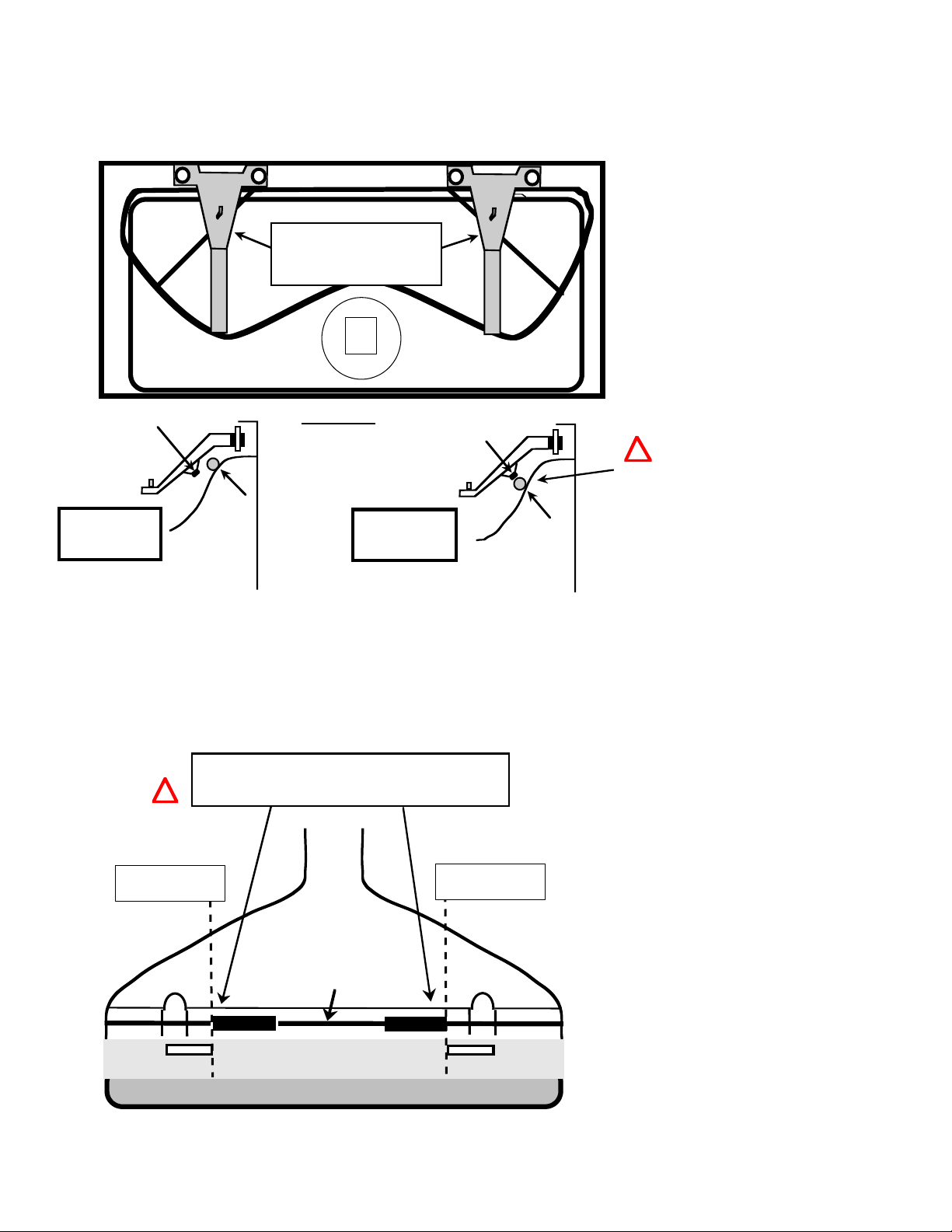
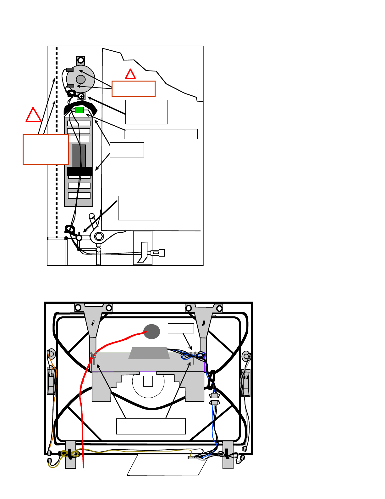
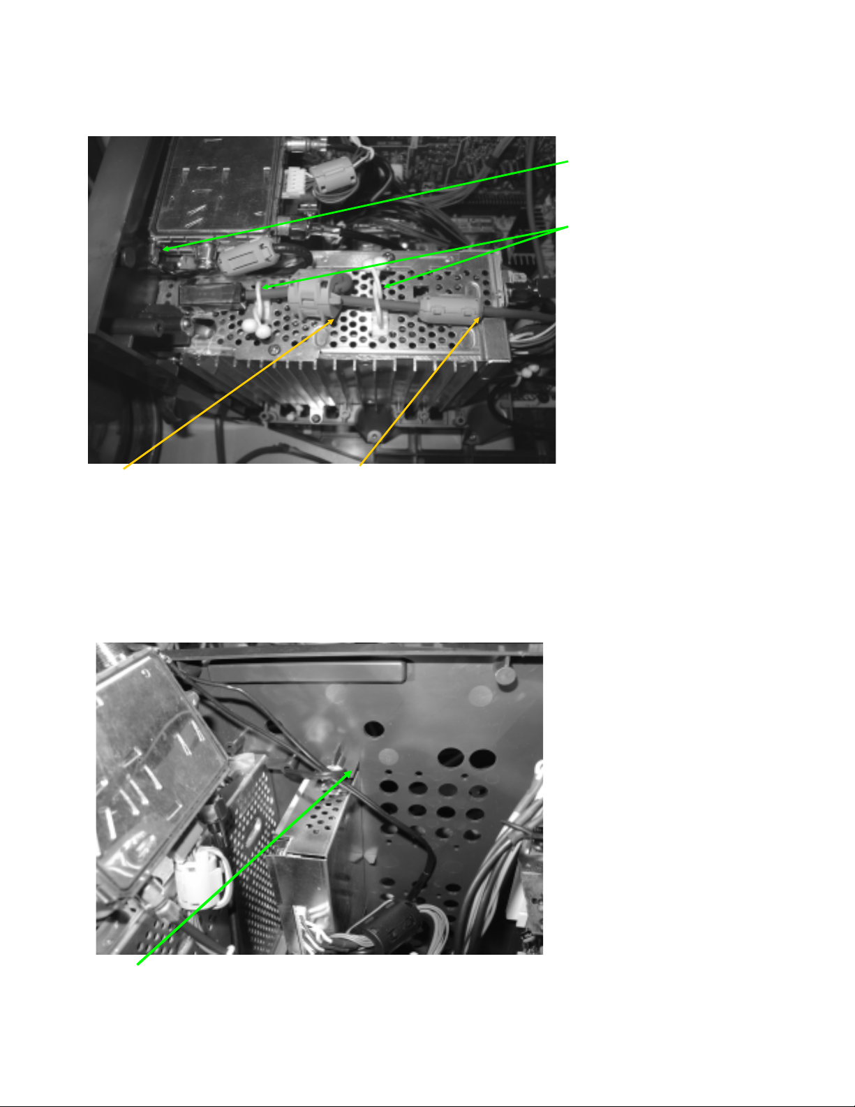
CABLE WIRE DRESSING
.
P
n
)
)
DY-SHIELD (ALL MODELS)
NOTE which hole DY
leads are dressed in!
E.C.G. Leads
KD-30XS955/34XBR960/34XS955/36XS955
NOTE: IF THE WIRE
DRESSING IS NOT
DONE PROPERLY,
IT MAY CAUSE
DISTORTION
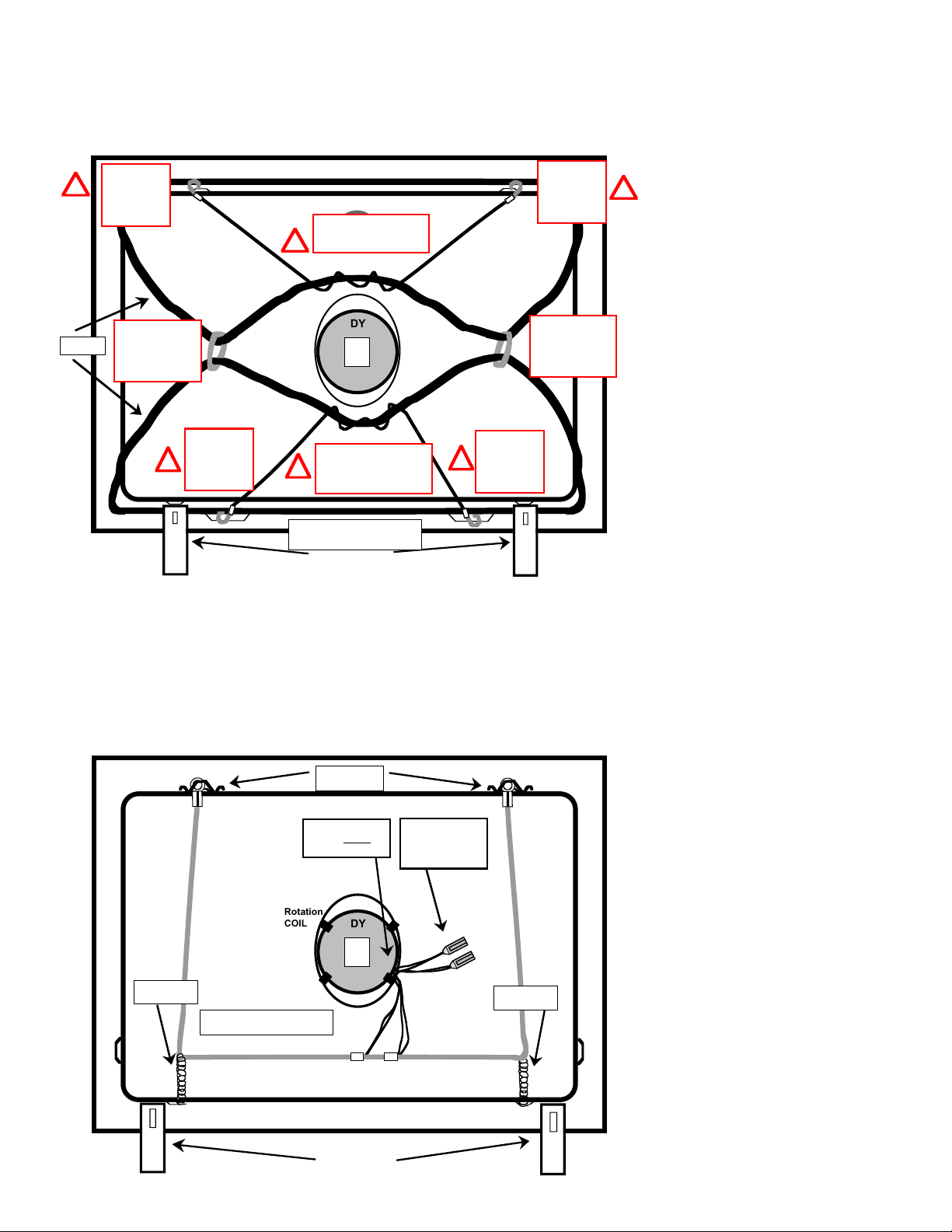
Rotation
COIL
9mm purselock
Attach to Rotation
Coil ABOVE DY CLI
DGC purselock
to hold DY Leads.
DGC Restraint Cable
E.C.G.
DY
Keep DY leads
away from B-Bd
(Noise Problems)
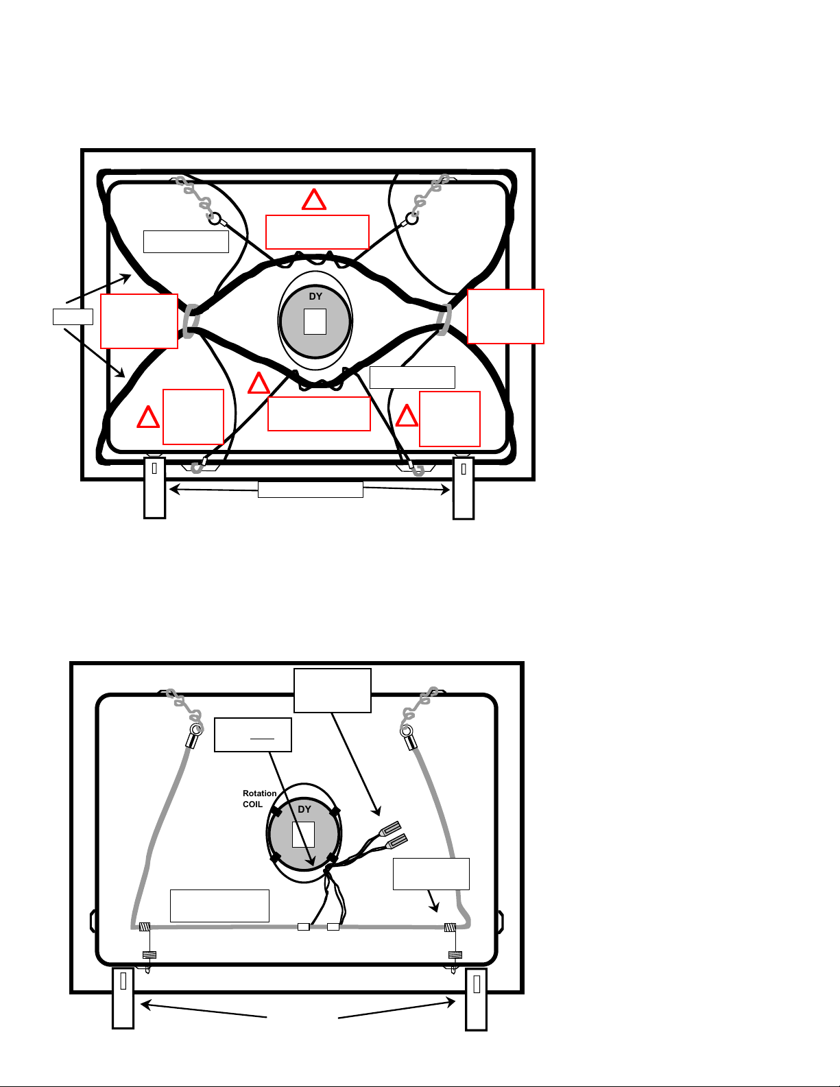
DCG/LCC CAUTION POINTS (ALL MODELS)
LCC
Coil
(Top)
Cable Tie
Dress DGC
leads through
Cable Ties!
Cable Tie
LCC
Coil
(Top)
Rotatio
COIL
DY
9mm purselock
attached to
Rotation Coil
ABOVE DY CLIP
ADHESIVE STRIPS
Place OVER ECG.
ECG MUST touch CRT in
this area!
!
Rev. 1
6/21/04
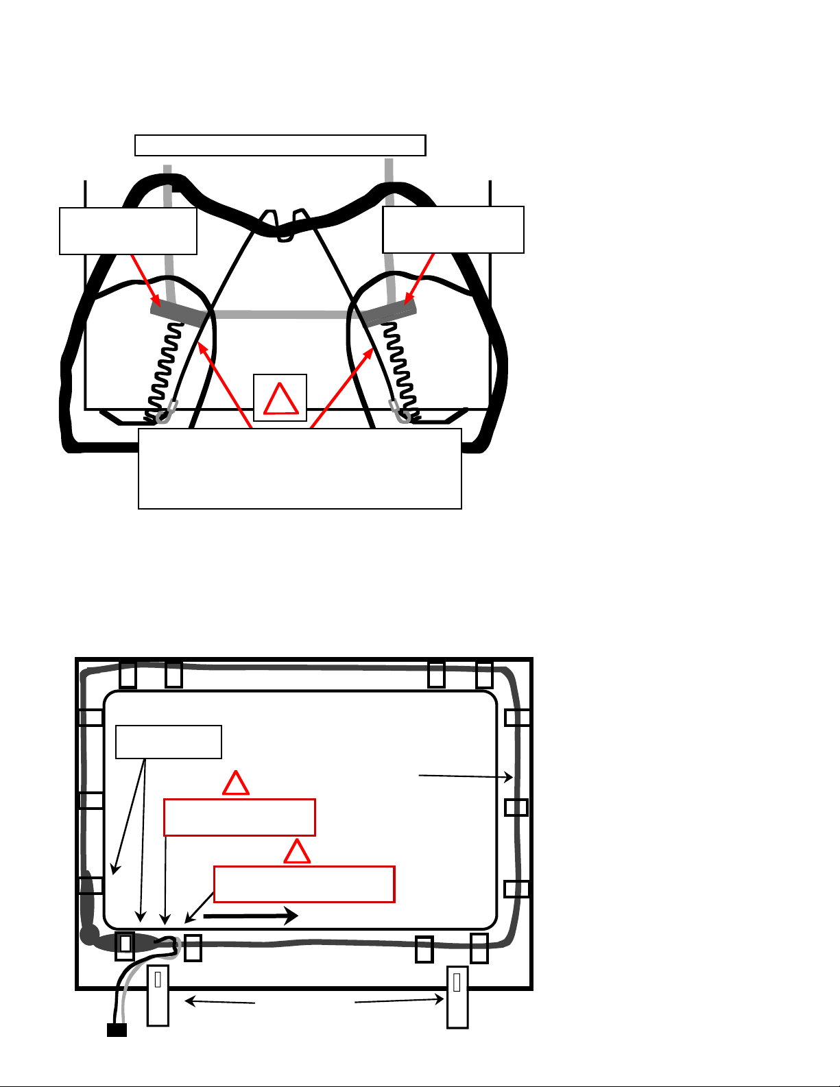
LCC
Coil
(Bottom
!
NOTE: MAKE SURE Cable Tie is
positioned so it does NOT
touch LCC COIL Wires! DO
[ DL ]
CN5805
NOT apply Cable Tie over
white/black LCC Tape!
!
NOTE: MAKE SURE wires are
not too tight! Leave some
Slack!
Rev. 1
6/28/04
KD-30XS955/34XBR960/34XS955/36XS955
LCC
Coil
(Bottom
To CN504/505
on A-Board
13

200V LEAD WIRE DRESSING CAUTION POINT (ALL MODELS)
Dress wires with
ONE LOOP in
[CX]
CLP9003
CN9002
CRT SOCKET
Clamp!
KD-30XS955/34XBR960/34XS955/36XS955
CLP9002
CN9003
ECG
SIDE VIEW
[WY]
3WIRE, 4p Conn. Assy.
p/n: 1-900-807-06
CN9004
ECG
B-Side
CN9109
G2
[CX]
CN9002
!
Dress Wire in Clamp
With ONE Loop.
The Loop Will take the
Stress off the
Connector
Header CN9002.
REV-1
6/28/04
KD-30XS955/34XBR960/34XS955/36XS955
14
KD-30XS955/34XBR960/34XS955/36XS955
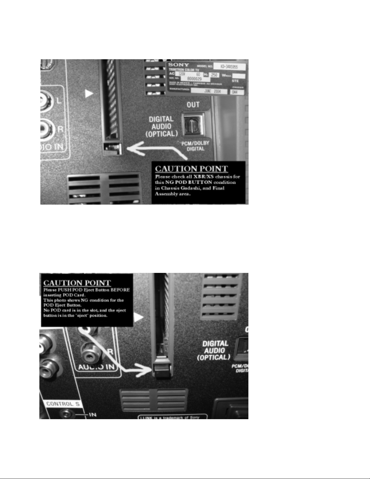
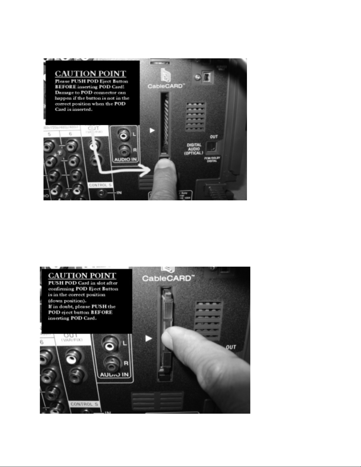
POD EJECT BUTTON CAUTIONS - ALIGNMENT CHECK (ALL MODELS)
This was a defect from Pre-Pro set. Important to check alignment of POD Eject Buttom.
VERY important if QBOX is replaced in the field.
POD EJECT BUTTON CAUTIONS - NG BUTTON POSITION (ALL MODELS)
KD-30XS955/34XBR960/34XS955/36XS955
15
KD-30XS955/34XBR960/34XS955/36XS955
POD EJECT BUTTON CAUTIONS - STEP 1 BEFORE INSERT CARD (ALL MODELS)
POD EJECT BUTTON CAUTIONS - STEP 2 INSERT CARD (ALL MODELS)
KD-30XS955/34XBR960/34XS955/36XS955
16

G2 WIRE ROUTING (ALL MODELS)
(ALL Models)
G2 WIRE
1-900-808-42
Dress wire in
“L” Shape.
FBT
REAR VIEW
KD-30XS955/34XBR960/34XS955/36XS955
REV-1
5/03/04
U-Bracket
Wire Holder
p/n: 4-065-850-11
O.K. CONDITION
SIDE VIEW
FBT
U-Bracket
Wire Holder
p/n: 4-065-850-11
!
G2 Wire MUST be routed correctly
so that the wire does NOT touch
Rear Cover (Causes “Buzzing” sound)
Route wire in front of U-Bracket!
N.G CONDITION
SIDE VIEW
N.G!
Wire can touch
Rear Cover!!
FBT
U-Bracket
KD-30XS955/34XBR960/34XS955/36XS955
17
WOOFER ARM WIRE DRESSING CAUTION (KD-34XBR960 ONLY)
L
E
E
KD-30XS955/34XBR960/34XS955/36XS955
Woofer Arm
Supporter
Woofer Arm
O. K.
Condition!
LCC
CRT
Make sure Woofer Arm does NOT
touch the LCC Coil!!
Weight of Woofer & Woofer Arm can
damage LCC if the Arm Supporter is
touching the Coil!!
SIDE VIEW
LCC
DY
Woofer Arm
N.G.
Condition!
Woofer Arm
Supporter
LCC
LCC
CRT
!
Touch!
N.G.
Rev. 1
6/28/04
CRT PREP CAUTION POINT (KD-34XBR960 ONLY)
4-079-129-21
50 x 20mm Himelon Tape
(Align with edge of Pierce [D Cut-Out] on HS-BAND)
!
ALIGN TAPE WITH EDG
OF D CUT-OUT
(TOLERANCE +-5mm)
ALIGN TAPE WITH EDG
OF D CUT-OUT
(TOLERANCE +- 5mm)
Bottom of
16X9 CRT
FRIT LINE
D Cut-Out
HS - BAND
FRONT PANE
D Cut-Out
Rev. 1
6/28/04
KD-30XS955/34XBR960/34XS955/36XS955
18
DGC ASSEMBLY CAUTION POINT (KD-34XBR960 ONLY)
N
T
T
T
T
N
Caution:
Make sure
hook is
secure on CR
pierce!
!
Caution:
Make sure
hook is
secure on CR
pierce!
1-900-803-55
DGC Restraint Cable
Wrap 2 TIMES (for 34W)
CHECK for NO SLACK O
WIRE!
!
KD-30XS955/34XBR960/34XS955/36XS955
!
DY
Wrap 2 TIMES (for 34W)
Wrap 4 TIMES (for 30W)
CHECK for NO SLACK O
WIRE!
1-900-803-55
DGC Restraint Cable
DGC
Caution:
Make sure Cable
Tie is TIGHTENED
once CRT is in
Vertical postion.
Caution:
Make sure
hook is
!
secure on CR
pierce!
!
CRT BRKT
34XBR p/n:4-093-523-xx
EGC WIRE DRESSING (KD-34XBR960 ONLY)
WIRE HOOK
4-097-355-01
Caution:
Make sure
hook is
!
secure on CR
pierce!
Caution:
Make sure Cable
Tie is TIGHTENED
once CRT is in
Vertical postion.
Rev. 1
6/28/04
NOTE: Leads are
dressed inside
Rotation Coil.
Rotation
SPRING
4-065-852-01
COIL
ECG - P/N’s
1-900-808-04 - 34 W CRT
DY
CRT BRKT
KD-30XS955/34XBR960/34XS955/36XS955
NOTE2: There are
2 Leads (TOTAL 4
Wires) to connect
to CX
SPRING
4-065-852-01
Rev. 1
6/28//04
19
CRT GROUND WIRE CAUTION POINT (KD-34XBR960 ONLY)
(
OK INSTALLATION w/ Countermeasure
DGC
DGC Tension Cable
p/n: 1-900-803-55
2-Loops for 34XBR
DGC
KD-30XS955/34XBR960/34XS955/36XS955
Himelon Tape
p/n: 4-079-129-21
Center Tape over the
END of the tension spring.
* Make sure DGC tension Cable (p/n:1-900-803-55)
does NOT cross over Tension Spring (p/n:4-065-852-01)!!
* Tension spring must NOT touch LCC Coils!
* CRT Ground Wire is CENTERED (as best as possible) upon
installation (so spring will not touch LCC Coil).
* DGC Tension Cable is CENTERED (as best as possible) upon
Installation
CRT Ground Wire
34XBR: 1-900-808-04
LCC Coil
LCC Coil
!
so that cable does not touch spring).
Himelon Tape
p/n: 4-079-129-21
Center Tape over the
END of the tension spring.
REV-1
6/28/04
N-S COIL WIRE DRESSING CAUTION POINT (KD-34XBR960 ONLY)
NOTE:
Thicker taping of N-S Coil
is clipped to Beznet Here.
North-South Coil (N-S)
1-424-695-11 (34XBR)
!
Make sure wires are routed
on the OUTSIDE of CRT
Support Bracket.
!
CAUTION:
Make sure direction of lead wires is
COUNTER-CLOCK-WISE!
DIRECTION OF LEAD WIRES
CRT BRKT X2
p/n: 4-093-523-XX (34XBR)
Rev.1
6/28/04
KD-30XS955/34XBR960/34XS955/36XS955
20

KD-30XS955/34XBR960/34XS955/36XS955
gp
e
SPEAKER ASSY. WIRE DRESSING - LEFT SPEAKERS (KD-34XBR960 ONLY)
Make sure tweeter
terminals are facing
AWAY from CRT!
CLAMP
P/N: 4-857-472-01
4X16mm Screw
p/n: 7-685-663-99
TORQUE: 12kg-cm +-1
Hold Capacitor down with Himelon tap
(to prevent vibration and touching CRT
HIMELON TAPE
P/N: 4-079-129-21
(2-PLACES)
+
Make sure Tweeter
leads do NOT touch
Beznet Rib (dashed
line)!!
Wires can Pinch when
Rear Cover is installed!
!
CRT
CLAMP
P/N: 4-857-472-01
4X16mm Screw
p/n: 7-685-663-99
TORQUE: 12kg-cm +-1
Rev. 1
6/28/04
KD-30XS955/34XBR960/34XS955/36XS955
21
KD-30XS955/34XBR960/34XS955/36XS955
SPEAKER ASSY. WIRE DRESSING - RIGHT SPEAKERS (KD-34XBR960 ONLY)
+
!
Make sure tweeter
terminals are facing
AWAY from CRT!
CLAMP
P/N: 4-857-472-01
4X16mm Screw
!
Make sure Tweeter
leads do NOT touch
Beznet Rib (dashed
line)!!
Wires can Pinch when
Rear Cover is installed!
p/n: 7-685-663-99
TORQUE: 12kg-cm +-1
Hold Capacitor down with Himelon tape
(to prevent vibration and touching CRT
HIMELON TAPE
P/N: 4-079-129-21
(2-PLACES)
CRT
CLAMP
P/N: 4-857-472-01
4X16mm Screw
p/n: 7-685-663-99
TORQUE: 12kg-cm +-1
+
Rev. 1
6/28/04
WOOFER ASSY. WIRE DRESSING (KD-34XBR960 ONLY)
Bundle slack
in Purselock.
Cable Tie
ANODE LEAD
DY
Purselock 4-072-499-01
(Install on Woofer Support Arm- Use
purselock hole on the LEFT side.)
ev. 1
/28/04
CRT Bracket
To FBT
KD-30XS955/34XBR960/34XS955/36XS955
[A]
CRT Bracket
22
CHASSIS DRESSING - HBZ BOARD AND USB (KD-34XBR960 ONLY)
1-900-808-02: 4P Conn Assy. w/RED housings
Dressed OUTSIDE 9mm black purselock
iLINK Cable (1-823-515-31) & 1-900-806-83: 11P Conn. Assy.
w/RED Taping. Dressed INSIDE 9mm black purselock.
1-900-805-24 Double Ground Wire w/ferrite core
(p/n: 1-500-082-11)
NOTE: Tab on AZ-Bd (CN 519) is bent over in 45degree angle.
USB Cable (p/n:1-829-191-11) black cable routed in H-Bracket
clips.
KD-30XS955/34XBR960/34XS955/36XS955
iLINK Cable (1-823-515-31) w/ I Holder plastic clip on HBZ-Bd
(p/n: 4-082-405-01)
CHASSIS DRESSING - QH BOARD (KD-34XBR960 ONLY)
1-900-805-24 dressed in H-bracket clips. USB CABLE dressed in H-Bracket clips.
NOTE: Mounted tab on QH board is bent 45degrees. NOTE Over-Molded Ferrite Position (important for EMI).
Also note ferrite core position (important for EMI).
KD-30XS955/34XBR960/34XS955/36XS955
23
KD-30XS955/34XBR960/34XS955/36XS955
CHASSIS DRESSING - WY AND CX CONNECTORS (KD-34XBR960 ONLY)
BOTH Connectors
Assys.
Connect to WY-BD
p/n: 1-900-808-02
w/ RED housing
(WY-Bd to DL-BD)
p/n: 1-900-808-32
6P Conn. Assy.
(BY-Bd to WY-BD)
11P Conn. Assy. w/Yellow Taping (p/n: 1-900-806-86) routed to CX-Bd. This end of 1-900-806-86 connects to CX-Bd
NOTE: This Conn. Assy. Is routed INSIDE the 9mm black purselock. NOTE: KNOT is only for picture. DO NOT knot
NOTE: 1-900-808-32, 6P Conn. Assy. Is routed INSIDE clamp (p/n: 4-857-472-01)
wires during actual dressing.
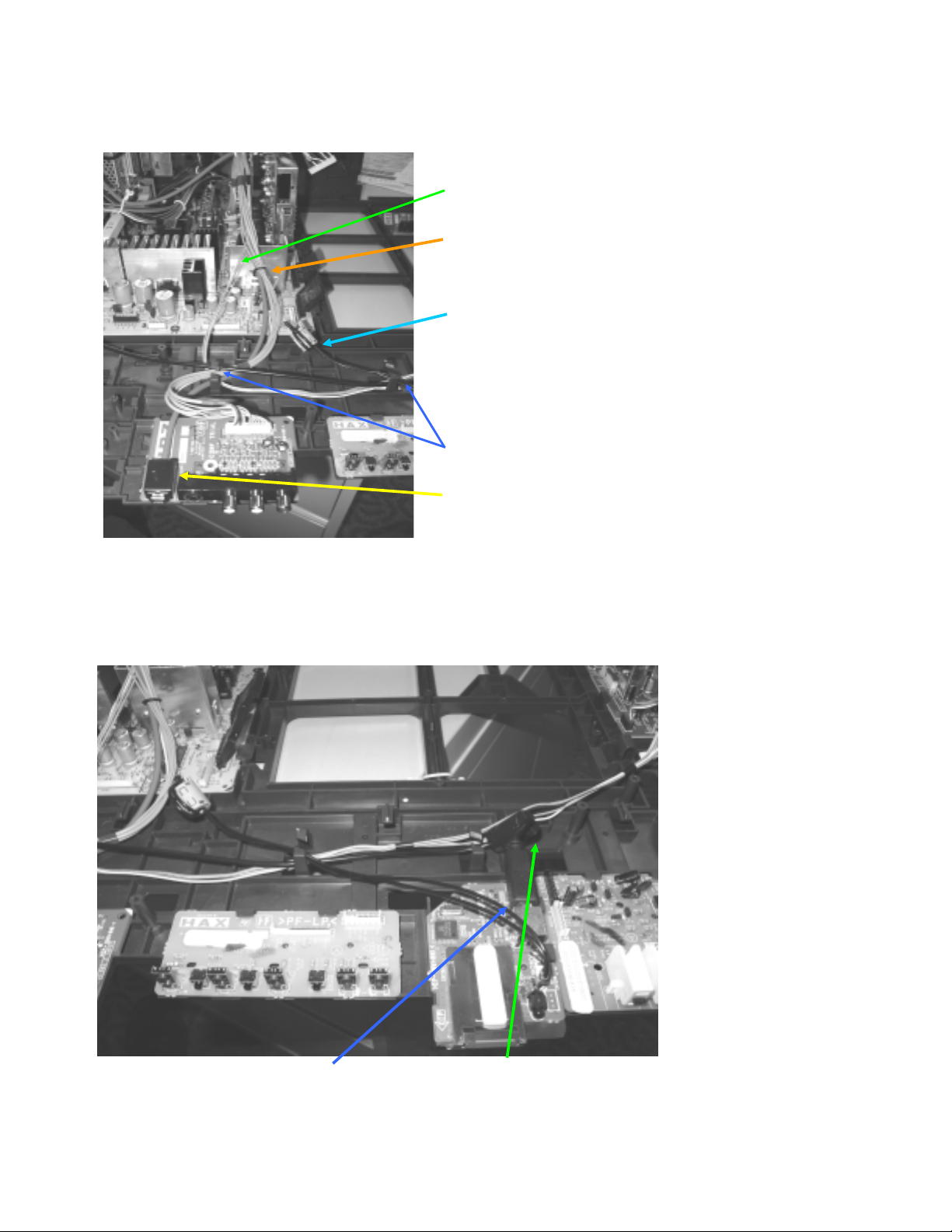
WIRE DRESSING - QBOX DRESSING (KD-34XBR960 ONLY)
KD-30XS955/34XBR960/34XS955/36XS955
24
KD-30XS955/34XBR960/34XS955/36XS955
WIRE DRESSING - QBOX DRESSING WITH CAUTIONS (KD-34XBR960 ONLY)
1-900-808-41 is dressed as far
BACK as possible
EMI Reasons
11mm purselock. p/n:3-703-983-02
Qty=4
iLINK cable NOT dressed in this
purselock
Main bundle dressed low as
possible. EMI Reasons
DO NOT let wires touch Cement
Resistor or heat sink
WIRE DRESSING - FERRITE ADDITIONS (KD-34XBR960 ONLY)
LOCATIONS OF FERRITE CORES
EFFECT EMI PERFORMANCE.
Please use caution when positioning ferrite cores!
KD-30XS955/34XBR960/34XS955/36XS955
25
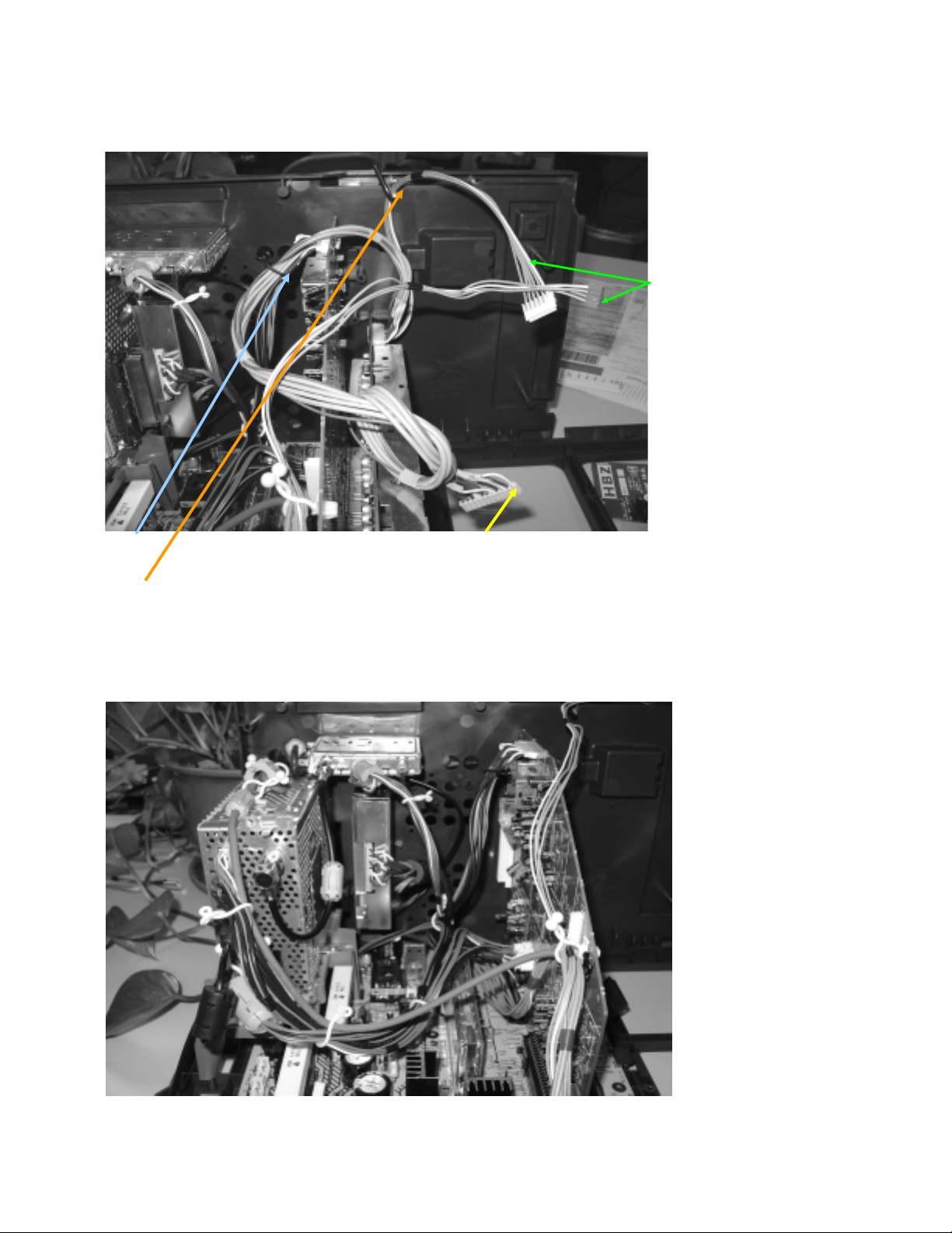
WIRE DRESSING - TOP OF QBOX (KD-34XBR960 ONLY)
KD-30XS955/34XBR960/34XS955/36XS955
1-900-805-24 ground
wire attached here
on Antenna Switch
Note direction of
purselocks and
postion of ferrite cores
Ferrite Core: NOTE LOCATION- IMPORTANT for EMI Ferrite Core: NOTE LOCATION- IMPORTANT for EMI
p/n: 1-500-484-21 p/n: 1-543-793-11
TDK ZCAT-2017-0930-M TDK ZCAT-1325-0530A
WIRE DRESSING - ANT SW GROUND WIRE (KD-34XBR960 ONLY)
1-900-805-24 ground wire is dressed in wire clamp. p/n: 4-857-472-01
Wire is dressed BEFORE securing position of Antenna Switch.
KD-30XS955/34XBR960/34XS955/36XS955
26

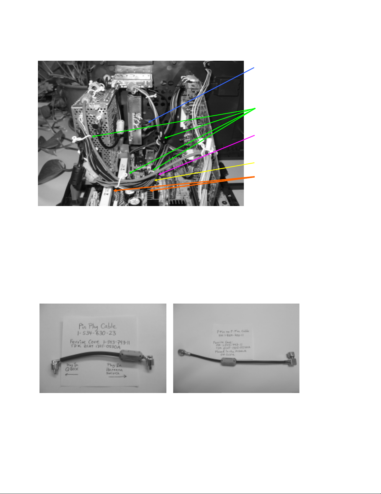
WIRE DRESSING - F-PIN DRESSING (KD-34XBR960 ONLY)
KD-30XS955/34XBR960/34XS955/36XS955
Note position (rotation of right-angle connector) of the cable/ferrite.
Do NOT dress the ferrite core so it can touch the Heat sink on the POD connector (not installed in this photo)
WIRE DRESSING -FRONT OF Q BOX (KD-34XBR960 ONLY)
NOTE " Z " Routing of USB Cable routing (important for EMI).
Position of Ferrite Core is Important for EMI.
KD-30XS955/34XBR960/34XS955/36XS955
27

KD-30XS955/34XBR960/34XS955/36XS955
WIRE DRESSING - 11MM P BOARD CONNECTION (KD-34XBR960 ONLY)
KD-30XS955/34XBR960/34XS955/36XS955
28

DCG LEAD WIRE DRESSING (ALL EXCEPT KD-34XBR960)
STEP1:
Make a loop in leads
and route loop BEHIND
The DGC Coil.
STEP 2:
Thread both connector
housings through the
loop in lead wires.
STEP 3:
Plug in connector
housings into the
[AZ] Board using the
loop to take up slack.
DY
Cable Tie
4-041-041-02
KD-30XS955/34XBR960/34XS955/36XS955
Rev. 1
5/10/04
KD-30XS955/34XBR960/34XS955/36XS955
29
T
T
DGC ASSEMBLY CAUTION POINT (KD-30XS955/34SX955 ONLY)
KD-30XS955/34XBR960/34XS955/36XS955
DGC
2-022-978-01
Wire Clip (2 Places)
1-910-000-13
DGC Restraint Cable
Caution:
Make sure Cable
Tie is TIGHTENED
once CRT is in
Vertical postion.
Caution:
Make sure
hook is
!
secure on CR
pierce!
!
Wrap x5 LOOP (for 30W)
Wrap x2 LOOP (for 34W)
NO SLACK ON WIRE!
DY
!
Wrap x5 LOOP (for 30W)
Wrap x2 LOOP (for 34W)
NO SLACK ON WIRE!
CRT BRACKET
1-900-803-55
DGC Restraint Cable
Caution:
Make sure
hook is
!
secure on CR
pierce!
Caution:
Make sure Cable
Tie is TIGHTENED
once CRT is in
Vertical postion.
Rev. 1
7/12/04
EGC WIRE DRESSING (KD-30XS955/34SX955 ONLY)
NOTE2: There are
2 Leads (TOTAL 4
Wires) to connect
2-022-978-01
Wire Clip (2 Places)
NOTE: Leads are
dressed inside
Rotation Coil.
Rotation
COIL
ECG - P/N
1-900-808-30 - 30 WCRT
1-900-808-31 - 34W CRT
to CX-Board
DY
CRT BRKT
SPRING (2 places)
Integral part of
the Ground wire
Rev. 1
7/12/04
KD-30XS955/34XBR960/34XS955/36XS955
30
 Loading...