

Page 1

SERVICE MANUAL
AE-6D
CHASSIS
MODEL
KD-32NX200U
COMMANDER DEST CHASSIS NO.
RM-939 UK SCC-Q84L-A
KD-32NX200U
- 1 -
RM-939
Page 2

TABLE OF CONTENTS
Section Title Pag e Section Title Pag e
Caution .................... 3
Specifications .................... 4
Connectors .................... 5
Self Diagnostic Software .................... 6
1. GENERAL
Automatically Tuning the TV .................... 9
Using a digital text service .................... 9
Using a conventional text service ................ 10
The EPG menu .................... 10
Using the TV menu system .................... 11
Vie wing memory stick pictures .................... 12
Remote Control operation of
VCR and DVD player ............... 13
Specifications .................... 14
Troubleshooting .................... 14
2. DISASSEMBLY
2-1. Rear Cover Removal .................... 15
2-2. Speaker Box Removal .................... 15
2-3. Chassis Removal and Refitting .................... 15
2-4. G1 Board Removal .................... 16
2-5. G Board Removal .................... 16
2-6. D2 Board Removal .................... 16
2-7. D1 Board Removal .................... 16
2-8. Service Position .................... 17
2-9. Wire Dressing 1 .................... 17
2-10. Wire Dressing 2 .................... 17
2-11. Wire Dressing 3 .................... 17
2-12. Picture Tube Remov al .................... 18
Bottom Plates .................... 19
3. SET-UP ADJUSTMENTS
3-1. Beam Landing .................... 20
3-2. Convergence .................... 21
3-3. Focus Adjustment .................... 23
3-4. Screen (G2), White Balance .................... 23
4. CIRCUIT ADJUSTMENTS
4-1. Electrical Adjustments .................... 24
4-2. Volume Electrical Adjustments .................... 28
4-3. T est Mode 2 .................... 29
ATTENTION
APRES AVOIR DECONNECTE LE CAP DE’LANODE,
COURT-CIRCUITER L’ANODE DU TUBE CATHODIQUE ET
CELUI DE L’ANODE DU CAP AU CHASSIS METALLIQUE DE
L’APPAREIL, OU AU COUCHE DE CARBONE PEINTE SUR LE
TUBE CATHODIQUE OU AU BLINDAGE DU TUBE
CATHODIQUE.
ATTENTION !!
AFIN D’EVITER TOUT RISQUE D’ELECTROCUTION
PROVENANT D’UN CHÁSSIS SOUS TENTION, UN
TRANSFORMATEUR D’ISOLEMENT DOIT ETRE UTILISÈ LORS
DE TOUT DÈPANNAGE LE CHÁSSIS DE CE RÈCEPTEUR EST
DIRECTMENT RACCORDÈ Á L’ALIMENTATION SECTEUR.
ATTENTION AUX COMPOSANTS RELATIFS Á
LA SECURITÈ!!
LES COMPOSANTS IDENTIFIÈS PAR UNE TRAME ET PAR UNE
MARQUE SUR LES SCHÈMAS DE PRINCIPE, LES VUES
EXPLOSÈES ET LES LISTES DE PIECES SONT D’UNE IMPOR-
TANCE CRITIQUE POUR LA SÈCURITÈ DU FONCTIONNEMENT,
NE LES REMPLACER QUE PAR DES COMPSANTS SONY DONT
LE NUMÈRO DE PIÈCE EST INDIQUÈ DANS LE PRÈSENT
MANUEL OU DANS DES SUPPLÈMENTS PUBLIÈS PAR SONY.
5. DIAGRAMS
5-1. Block Diagrams (1) .................... 31
Block Diagrams (2) .................... 32
Block Diagrams (3) .................... 33
Block Diagrams (4) .................... 34
Block Diagrams (5) .................... 35
5-2. Circuit Board Location .................... 35
5-3. Schematic Diagrams and
Printed Wiring Boards .................... 35
* A Board PWB .................... 36
* A Board Schematic .................... 39
* B5 Board PWB ................. 48
* B5 Board Schematic .................... 49
* C1 Board PWB .................... 57
* C1 Board Schematic .................... 58
* H Board PWB .................... 57
* H Board Schematic .................... 59
* MS2 Board PWB .................... 57
* MS2 Board Schematic .............. 59
* D1 Board PWB .................... 60
* D1 Board Schematic .................... 61
* G1 Board PWB .................... 63
* G1 Board Schematic .................... 62
* D2 Board PWB .................... 63
* D2 Board Schematic .................... 64
* M2 Board PWB .................... 65
* M2 Board Schematic.................... 66
* G Board PWB .................... 68
* G Board Schematic ................... 67
* VM Board PWB ................. 68
* VM Board Schematic ................ 69
* F3 Board PWB .................... 70
* F3 Board Schematic .................... 69
* H3 Board PWB .................... 70
* H3 Board Schematic .................... 71
* J3 Board PWB .................... 70
* J3 Board Schematic .................... 72
5-4. Semiconductors .................... 74
5-5. IC Blocks .................... 76
6. EXPLODED VIEWS
6-1. Chassis .................... 79
6-2. Picture Tube .................... 80
7. ELECTRICAL PARTS LIST .................... 81
SHORT CIRCUIT THE ANODE OF THE PICTURE TUBE AND THE
ANODE CAP TO THE METAL CHASSIS, CRT SHIELD, OR THE
CARBON PAINTED ON THE CRT, AFTER REMOVAL OF THE
ANODE CAP.
AN ISOLATION TRANSFORMER SHOULD BE USED DURING
ANY SERVICE WORK TO AVOID POSSIBLE SHOCK HAZARD
DUE TO LIVE CHASSIS, THE CHASSIS OF THIS RECEIVER IS
DIRECTLY CONNECTED TO THE POWER LINE.
SAFETY-RELATED COMPONENT WARNING !!
COMPONENTS IDENTIFIED BY SHADING AND MARKED
THE SCHEMATIC DIAGRAMS, EXPLODED VIEWS AND IN THE
PARTS LIST ARE CRITICAL FOR SAFE OPERATION. REPLACE
THESE COMPONENTS WITH SONY PARTS WHOSE PART
NUMBERS APPEAR AS SHOWN IN THIS MANUAL OR IN
SUPPLEMENTS PUBLISHED BY SONY.
CAUTION
WARNING !!
ON
- 2 -
Page 3

CAUTION
Lead Free Soldered Boards
The circuit boards listed below [T able 1] used in these models may
have been processed using Lead Free Solder . The boards are
identified by the LF logo located close to the board designation e.g.
F1, H1 etc [ see examples ]. The servicing of these boards requires
special precautions to be taken as outlined below .
Table 1
draoB noitcnuF
example 1
example 2
3H
dnaenohpdaeH,tupnIVAtnorF
sehctiwSlortnoC
It is strongly recommended to use Lead Free Solder material in order to guarantee optimal quality of new solder joints. Lead Free Solder is
available under the following part numbers :
rebmuntraP retemaiD skrameR
91-500-046-7mm3.0gK52.0
02-500-046-7mm4.0gK05.0
12-500-046-7mm5.0gK05.0
22-500-046-7mm6.0gK52.0
32-500-046-7mm8.0gK00.1
42-500-046-7mm0.1gK00.1
52-500-046-7mm2.1gK00.1
62-500-046-7mm6.1gK00.1
Due to the higher melting point of Lead Free Solder the soldering iron tip temperature needs to be set to 370 degrees centigrade. This requires
soldering equipment capable of accurate temperature control coupled with a good heat recovery characteristics.
For more information on the use of Lead Free Solder, please refer to http://www.sony-training.com
- 3 -
Page 4
LEDOMMETI metsySnoisiveleT metsySoeretS egarevoClennahC metsySroloC
How to replace the fuse.
Open the fuse compartment with
a screwdriver blade and replace
the fuse.
FUSE
UT-BVD,I
ebuTerutciP
skcaJonohP
tekcoSAICMCP
kcajenohpdaeHkcajinimoerets
stupnioiduAskcajonohp
stupnioediVskcajonohp
tupnioediVSNIDnip4
MACIN
oeretS
nortinirTDF
)yllanogaid
]RAER[slanimreTtuptuO/tupnI snoitacificepSlareneG
rotcennocoruEnip-12:1
)dradnatsCELENEC(
rotcennocoruEnip-12:2
rotcennocoruEnip-12:3
slangiS
.BGRrofstupnI
.slangis
.BGRrofstupnI
.slangis
)elbatceles(
]TNORF[slanimreTtuptuO/tupnI lortnocderarfnI:metsyslortnocetomeR
)sehcni23(mc28xorppA
derusaemerutcipmc67xorppA(
noitcelfedeerged°201
.slangisoediVdnaoiduArofstupnI
oiduAdnaoediVVTfostuptuO
.slangisoediVdnaoiduArofstupnI
oiduAdnaoediVVTfostuptuO
.slangisoediVdnaoiduArofstupnI
.oediVSrofstupnI
slangisoiduAdnaoediVrofstuptuO
oiduArofelbairavsrotcennoCtuptuO
eludoMsseccAlanoitidnoC
96B-12B:FHU
tuptuOdnuoS
rekaepstfeLdnathgiR
refoowbuS
stnemeriuqeRrewoPV042-022
noitpmusnoCrewoPW451
snoisnemiDmm095x5.544x019xorppA
thgieWgk76xorppA
seirosseccAdeilppuS
serutaeFrehtO
stnemeriuqerrewoP
rednammoCetomeR939-MR
elbachguorhtpooLFR
EBB,ybloDlautriV,yromeM
cdV3
noitangisedCEIseirettab2
)AAezis(6R
,85.3CSTN,LAP
)NIOEDIV(34.4CSTN
LM@PM,2-GEPM
)SMR(W01x2)rewoPcisuM(W02x2
)SMR(W51x1)rewoPcisuM(W03x1
)2(yrettab6RdetangisedCEI
txeteleTegaP0002,POH,RND,FCD,FMCRD
metI
PAPFFO
PIPFFO
ytiroirPBGRNO
xoBrefooWNO
1tracSNO
2tracSNO
)4(nitnorFNO
3tracSNO
rotcejorPFFO
G/BmroNFFO
ImroNNO
K/DmroNFFO
SUAmroNFFO
LmroNFFO
TASmroNFFO
MmroNFFO
txeteleTNO
emaNledoM
oeretSmaciNNO
.ecitontuohtiwegnahcottcejbuserasnoitacificepsdnangiseD
U002XN23-DK
WARNING (UK Models only)
The flexible mains lead is supplied connected to a B.S. 1363 fused
plug having a fuse of 5 AMP rating. Should the fuse need to be
replaced, use a 5AMP FUSE approved by ASTA to BS 1362, ie one
ASA
that carries the
IF THE PLUG SUPPLIED WITH THIS APPLIANCE IS NOT SUITABLE FOR THE OUTLET SOCKETS IN YOUR HOME, IT SHOULD
BE CUT OFF AND AN APPROPRIATE PLUG FITTED. THE PLUG
SEVERED FROM THE MAINS LEAD MUST BE DESTROYED AS A
PLUG WITH BARED WIRES IS DANGEROUS IF ENGAGED IN A
LIVE SOCKET.
T
mark.
When an alternative type of plug is used, it should be fitted with a
5 AMP FUSE, otherwise the circuit should be protected by a 5AMP
FUSE at the distribution board.
- 4 -
Page 5
21 pin connector
21
19
17
15
13
11
9
7
5
3
1
20
18
16
14
12
10
8
6
4
2
Pin No 1 2 4 Signal Signal level
1 Audio output B
2
3
4 Ground (audio)
5 Ground (blue)
6 Audio input A
7 Blue input 0.7 +/- 3dB, 75 ohms positive
8 Function select
9 Ground (green)
10 Open
11 Green Green signal : 0.7 +/- 3dB, 75 ohms,
12 Open
13 Ground (red)
14 Ground (blanking)
15
16 Blanking input
17 Ground (video
18 Ground (video
19 Video output 1V +/- 3dB, 75ohms, positive sync 0.3V
20
21 Common ground
3
(right)
Audio input B
(right)
Audio output A
(left)
(left)
(AV control)
_ _ Red input 0.7 +/- 3dB, 75 ohms, positive
_ (S signal Chroma
input)
(Ys signal)
output)
input)
_ _ Video input 1V +/- 3dB, 75ohms, positive sync 0.3V
_ Video input
Y (S signal)
(plug, shield)
Standard level : 0.5V rms
Output impedence : Less than 1kohm*
Standard level : 0.5V rms
Output impedence : More than 10kohm*
Standard level : 0.5V rms
Output impedence : Less than 1kohm*
Standard level : 0.5V rms
Output impedence : More than 10kohm*
High state (9.5-12V) : Part mode
Low state (0-2V) : TV mode
Input impedence : More than 10K ohms
Input capacitance : Less than 2nF
positive
0.3 +/- 3dB, 75 ohms, positive
High state (1-3V) Low state (0-0.4V)
Input impedence : 75 ohms
(-3+10dB)
(-3+10dB)
1V +/- 3dB, 75ohms, positive sync 0.3V
(-3+10dB)
Connected Not Connected (open) * at 20Hz - 20kHz
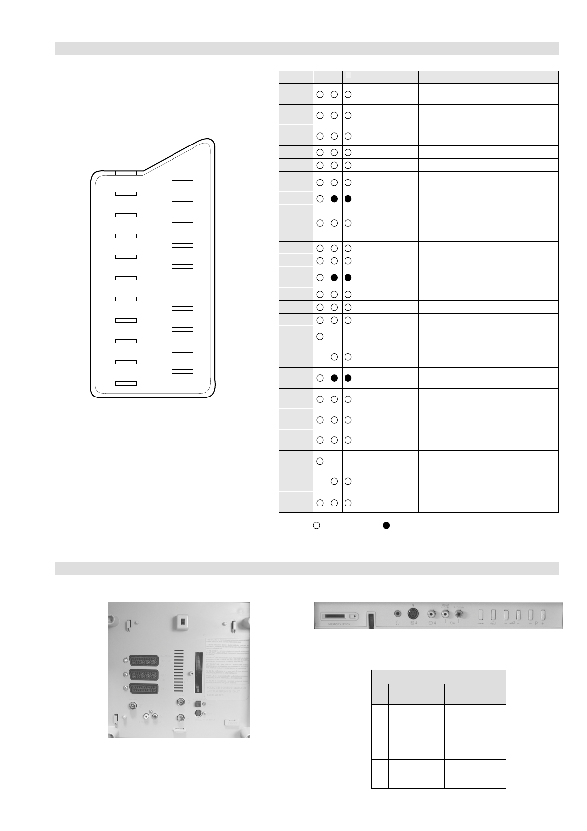
Rear Connection Panel Front Connection Panel
S-Video
socket
niP
oN
1dnuorG2dnuorG3tupni)langisS(Y,mho57Bd3-/+V1
4tupni)langisS(CBd3-/+V3.0
langiS leveLlangiS
noitarugifnocniptekcosoediVS
V3.0.cnySevitisop
Bd01+3-
evitisop,mho57
.cnyS
- 5 -
Page 6
AE-6D SELF DIAGNOSTIC SOFTWARE
The identification of errors within the AE-6D chassis is triggered in one of tw o ways :- 1: Busy or 2: De vice failure to respond to IIC. In the
event of one of these situations arising the software will first try to release the bus if busy (Failure to do so will report with a continuous
flashing LED) and then communicate with each device in turn to establish if a device is f aulty . If a device is found to be faulty the rele v ant
device number will be displayed through the LED (Series of flashes which must be counted) See table 1., non fatal errors are reported using this
method.
metIcitsongaiD
noitpircseD
nonruttonseodrewoPthgiltonseoD
)PCO(tnerrucrevOB+semit2
deppotsnoitcelfeDlacitreVsemit4
ybdnatSsemitfooN
sehsalFDEL
.tiucricneposiesuF
egasseMrorrE
devreseR 10
)noitcetorPtnerruCrevO(PCO 20
)noitcetorPegatloVrevO(PVO 30
noitcetorPlacitreV 40
noitcetorPlatnoziroH 60
noitcetorPrekaepS 70
rorrEsuBC2I 80
MVN,23C42TS.B-2M 90
draoB-A 01
draoB5B 11
draoB2J 21
draoBH 31
draoBSM 41
redoceDruoloCniaM.B-5B 51
dnekcaB,Q0512AXC.B-A 61
.corPdnuoS,1143PSM.B-A 71
desutoN 23-81
esuacelbaborP
noitacoL
.nideggulptonsidrocrewoP
)draoB1D(.detrohssi)3018/2018Q(TUO.H
)draoB1D(.detrohssi)6018Q(TEFytiraeniL
)draoB1D(.detrohssiCIrewoP1088CI
)draoB1D(nepo7028RdeilppustonsiV51+
)draoB1D(nepo6028RdeilppustonsiV51-
)draoBA(detrohssi1071CI
)edoMnoitcudorPnidelbasid,s03retfastratskcehc(BKAelbatsnU 50
smotpmySdetceteD
noemoctonseodrewoP
VTehtotdeilppussirewopoN
ytluafsiylppusrewopCA
noemoctonseodrewoP
detrohssahenilrewopnodaoL
deppotssaheslupnoitcelfedlacitreV
detrohssahenilrewoP
DEL
edoC
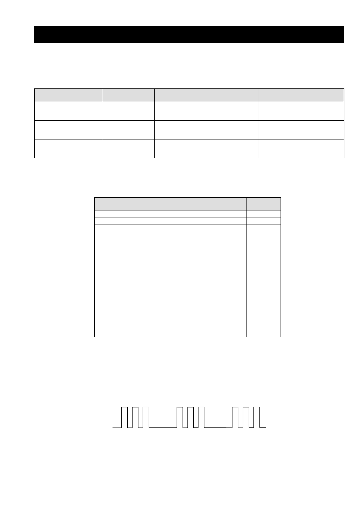
Flash Timing Example : e.g. error number 3
StBy LED
ON ON ON
OFF
- 6 -
OFF
Page 7
Error Detection Monitor
Device acknowledge is used to check IIC errors. De vice ackno wledge is checked by sending an IIC start sequence during CR T po wer on. Each
device is checked three times, if there is no acknowledge after each attempt, it will be re garded as an error.
There are three steps to check for errors.
1. IIC line 0
If all devices except the NVM have errors, IIC line 0 error is displayed.
2. Board check
If all devices mounted on one board have errors, board error is displayed.
3. Each device check
If IIC line error and board error are not detected then the device with the error is displayed.
The detected errors can be displayed as follows :
1. Error Monitor Menu.
2. Error Reader .
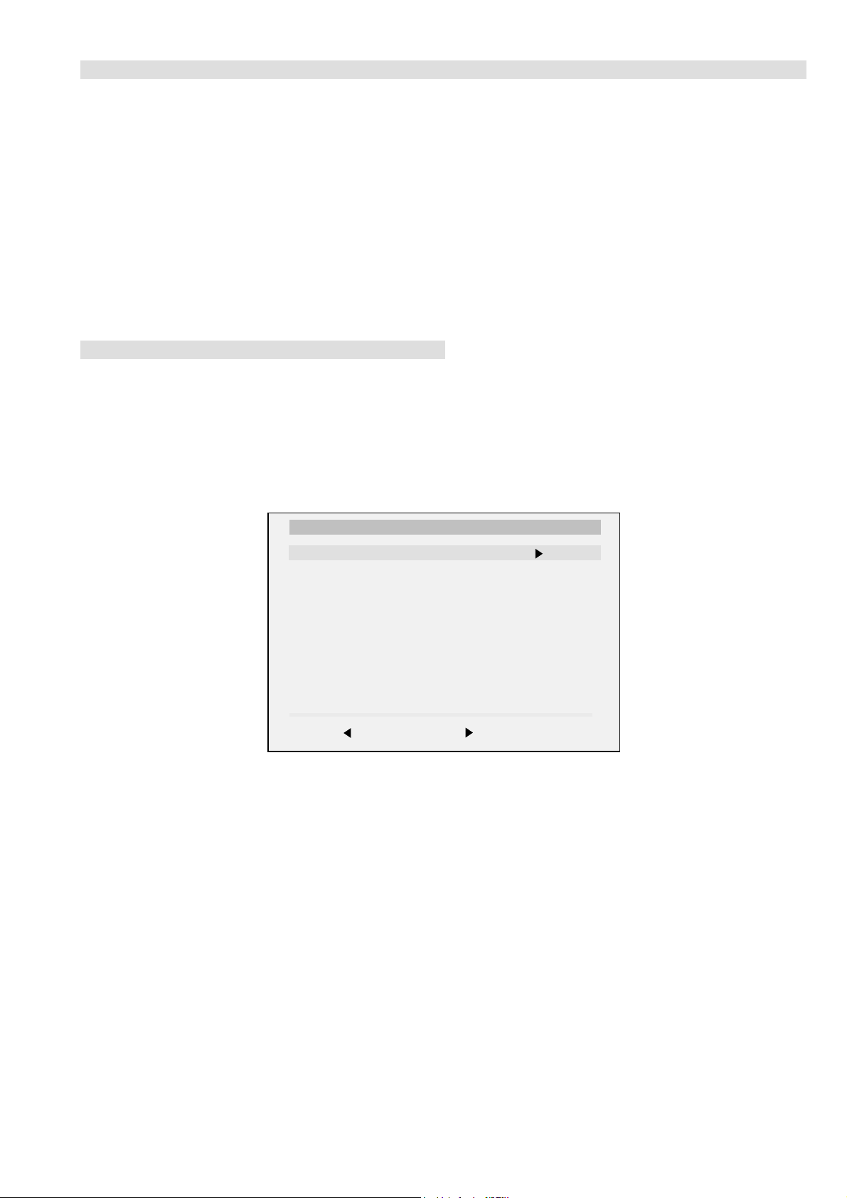
1. Error Monitor Menu
ERROR MONITOR
1. IGNORE ERRORS OFF ON OFF
Operating Time : 000167 h 45 min
Stored Errors :
1. A - B TU1350 Sub-Tuner
2. J - B TDA9320 Sub Col. Dec.
3. No Error Occured
4. No Error Occured
5. No Error Occured
Current Error :
A - B TU1350 Sub-Tuner
Last menu Enter item
- 7 -
Page 8

2. Error Reader Display
The error reader display is connected to the service connector to read actual error codes. The part number for the error reader display is
S-188-900-10. Once an error has been detected it will then be displayed on the two digit error reader. The errors displayed refer to the following
table.
edoCrorrE egasseMrorrE
h000deruccOrorrEoN
h1000C2I,rorrEsuB
h2001C2I,rorrEsuB
h3002C2I,rorrEsuB
h001draoB-A
h101.pxEtroP,5781AXC.B-A
h201renuT-niaM,xx06UT.B-A
h301FIniaM,6889ADT.B-A
h401dnekcaB,Q0512AXC.B-A
h501CAD,14188BM.B-A
h601.corPdnuoS,G1143PSM.B-A
h701.vnoC.anyD,0708AXC.B-A
h002draoB-5B
h102redoceDruoloCniaM.B-5B
h202redoceDruoloCbuS.B-5B
h302XDIM.B-5B
h402yarrAetaGamaronaP.B-5B
h502noitcudeResioN.giD.B-5B
h003draoB-H
h103kniLVA,8802DXC.B-H
h004draoB-J
h104hctiwSVA,5581AXC.B-2J
h204hctiwSVA,9412AXC.B-2J
h304renuT-buS,xx06UT.B-2J
h404FIbuS,6889ADT.B-2J
h005draoB-2M
h105MVN,23C42TS.B-2M
h006draoB-1SM
h106kcitSyromeM.B-1SM
- 8 -
Page 9
SECTION 1 GENERAL
Basic operation
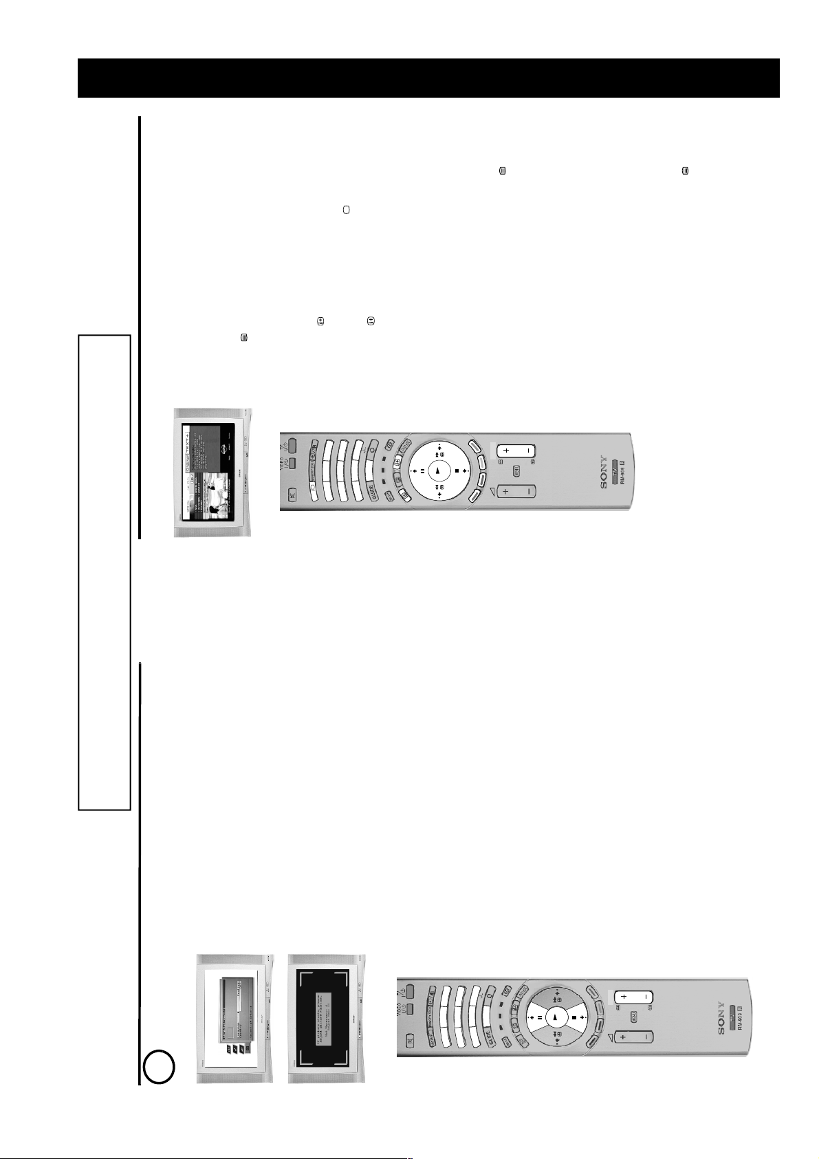
Using a digital text service
mode.
Press the button on the remote control to check if you are in digital
mode. If you are watching a digital programme an Info display appears on
screen providing brief details for the current and next programme. If the
display does not appear, press the DIGITAL/ button to switch to digital
Press the button to remove the Info display from the TV screen then
Most digital TV channels broadcast information via their te xt service. This digital service
includes high quality text and graphics along with advanced navigation options.
Additionally, this TV has access to dedicated text channels transmitted by the
broadcasting authorities. The appearance, content and navigation methods of all digital
text services are decided by the broadcaster. For example, the BBC’s d igi tal text service
may look different to ITV’s digital text. However, the digital text services currently
available use simple navigation methods based on the following butt ons:
The text button to load up the digital text,
The V, v, B and b buttons (to mov e aroun d the scre en) ,
The OK button or the numbered buttons (to select items on screen),
The four coloured buttons (to access shortcuts).
1.
Selecting a dedicated digital text channel
3
2
L
L
1
A
A
IT
IT
IG
IG
D
D
6
9
0
8
5
7
4
menu’ section of this manual.)
select the programme number that is broadcasting the dedicated digital text
channel by using the numbered buttons on the remote control. If you do not
know the channel number of a dedicated digital text channel, you can use
the ‘Channel Index menu’ to find one. (Please refer to the ‘Channel index
Once the text page is displayed, follow the on-screen instructions to obtain
your required selection.
Note: On some pages the TV programme may also be displayed on the text screen.
On-screen instructions will inform you how to change the displayed programme.
If you are instructed to press ‘OK’ or ‘Select’ when viewing the text pages,
press the OK button.5.When you have finished viewing the t ext service, press the button to exit.
2.
D
V
D
V
T
R
T
V
3.
4.
PROG
OK
Selecting a text service from other digital channels
Press the V, v, B, or b buttons to select the symbol, then press the OK
button to display the chosen information.2.Alternatively, you may be instructed to use the numbered or coloured buttons
on your remote control to display the various pages of text information. If you
are instructed to press ‘OK’ or ‘Select’ when viewing the text pages, press
the OK button.3.Once the text information is displayed, you can access requ ired information
by using the V, v, B, or b buttons, the coloured buttons an d/or the numbered
When you have finished viewing the t ext service, press the button to exit.
buttons on the remote control.
1.
Normal text services may also be available on other digital channels. This is sometimes
indicated by a small symbol on your TV screen, superimposed on the programme you
are watching.
4.
10
The operating instructions mentioned here are partial abstracts from the ‘Operating
Instruction Manual’. The page numbers of the ‘Operating Instruction Manual’ remain
as in the manual.
Getting started
button to rotate the picture over a range of -5 to +5. Press the OK button
The picture rotatio n prompt appears. Sometimes the Ea rth ’ s natural
to store.
magnetism can cause the screen to look tilted.
a) If no correction is required, press the B button.
b) If some correction is required, press the OK button. Press the V or v
The autotune prompt screen appears. Press the OK button to select Yes and
begin the digital autotune procedure.
When all the available digital programmes are found, the analogue tuning
display appears and all the analogue signals are captured and stored.
If no digital and no analogue signals are found, a display appears on screen
asking you t o confirm your ae rial is connected. Check your aerial is
connected then press the OK button to repea t the tunin g proc edu re.
Once all signals have been captured and stored, the TV returns to normal
operation and displays the digital programme captured on programme
number 1.
the remote control.
Note: If no digital signals are captured, then the analogue programme stored on
programme number 1 is displayed.
To vie w progra mm es, press the PROG+/- button or the numbered buttons on
3.
3
9
6
D
V
D
V
0
8
2
5
T
R
T
1
V
7
4
OK
PROG
choice.
control to highlight your required language. Press the OK button to confirm
When you switch on the TV for the first time, the Sony logo appears on the TV
screen followed by the ‘Memory Stick’ logo, then th e Language/Country menu
country in which you are using the TV. Press the OK button to confirm your
with the word ‘English’ highlighted. Press the V or v buttons on the remote
your choice. From now on all menus appear in your chosen language.2.The word Country is now highlighted. Press the V or v buttons to high light the
Note: The digital features of this set are designed for use in Great Britain only.
1.
Automatically tuning the TV
5
6
- 9 -
Page 10
Basic operation
11
D
IG
IT
A
L
D
IG
IT
A
L
OK
1
4
7
3
6
9
2
5
8
0
PROG
V
T
R
T
V
DVD
Using a conventional text service
Most analogue TV channels broadcast a text service. The index page (usually page
100) provides information on how to use the service. Please ensure you are receiving a
strong signal or some text errors may occur.
Switching on the text service
How to use the text features
1
Press the button on the remote control to check if you are in analogue
mode. If you are watching a digital programme an Info display appears on
screen providing brief details f or the curren t and ne xt progr amm e. To change
to analogue programmes press the DIGITAL/ button.2Select the TV channel that carries the text service you wish to view3Press the button to enter Picture and Text (P&T) mode. The screen is
divided into two with the Text display on the left and the TV channel in the
right corner.
Press the button a second time to enter full screen Text mode.
Press the button a third time to enter Mix mode.4Press the numbere d buttons to ent er a three di git number for the text page
you wish to view. Your selected page appears on screen.5Enter more 3 digit page numbers as required.6When you have finished viewing the text service, press the DIGITAL/
button to remove the text display from the screen.
Text Features How to select
To select the next or
preceding page
Press the or button.
To select a sub page A text page can consist of several sub pages. In this case
an information box is displayed at the bottom of the screen
showing the number of su b pages a v aila bl e. Se lect th e sub
pages by pressing the V or v button.
To keep a page on
display
Press the button. Press again to cancel.
To use Fastext Fastext allows you to access pages with one button push.
When Fastext is available, four coloured items appear at
the bottom of the screen. Press the corresponding
coloured button on the remote control to display the page.
To use the Page
Catching feature
Select a page that contains several page numbers (e.g.
the index page), then press the OK button. Press the V or
v button to highlight the page number required, then press
the OK button again. Your selected page appears on
screen.
Digital features
22
OK
D
IG
IT
A
L
D
IG
IT
AL
V
T
R
T
V
D
V
D
OK
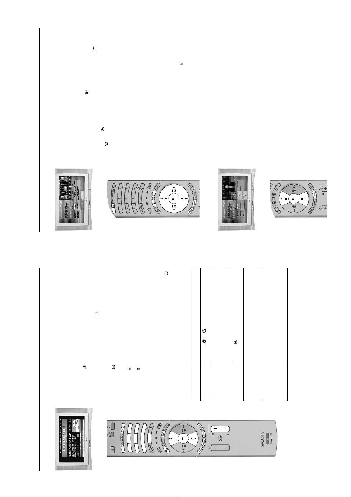
The EPG menu
The EPG menu (Electronic Programme Guide) provides a quick and easy way to:-
a) View a complete list of the programmes available.
b) Obtain a preview of the programmes currently being broadcast.
c) Create a list relating to a category of programme, e.g. Sports or Movies.
d) Record programmes.
The Category pop-up list
The Category pop-up list allows you to search for programmes quickly by dividing the
channels into different categories. For example, if you select ‘News’ from the Category
pop-up list, then only programmes related to News will be shown in the EPG menu.
1.
The EPG menu is only available when watching digital channels. To check if
you are in digital mode, pr ess the button on the remote control. An Info
display appears on screen providing brief details for the current and next
programme. If the display does not appear, press the DIGITAL/ button. 2.Press the button to remove the Info dis play from the s creen then press the
button to display the EPG menu screen. This screen consists of an
information window, a preview window, a 2 hour timer bar (divided into 30
minute intervals) and a 5 channe l programme list covering the 2 hour period.3.Press the V or v buttons to move the cursor bar up or down the programme
list and the b or B buttons to mov e left and right. If you pre ss the b butt on once
more after highl ighting the last programme o n the right, the programme s
scheduled for the next 2 hour period are displayed. As each programme is
highlighted, a brief description of the programme appears in the event
information box at the top left of the screen. If you do not wish to select a
programme from the 5 channels liste d, press the GREEN button to display the
next 5 channels or RED button to display the previous 5 channels.
4.
If a programme you highlight is currently being broadcast, you will be
prompted to press the OK button to obtain a preview.
*Note:If an age limit for viewing has been set and the programme selected exceeds
that age limit, you will need to enter your PIN code before the preview is displayed.
Refer to ‘The Main menu’ for more information on the ‘PIN Code’ feature. Programmes
that exceed the age limit you have set will be identified by a symbol.
5.
When the programme in the preview screen is the one you want, press the
OK button to exit the EPG menu and view the programme at full size.
1.
With the EPG menu on screen, press the YELLOW button to display the
Category pop-up list.2.Press the V or v buttons to highlight the category you want, then press the
OK button. The EPG programme l ist will now o nly contai n program mes of the
type selected.
For information on the category types as well as instructions on how to add
and remove programmes from the F avourite lis t, please re fer to ‘The Channel
Index menu’ section on the previous page.
- 10 -
Page 11
TV menu system
24
OK
MENU
The following pages explains the TV set up menus and their operation. Although most of these menus can be accessed whilst
watching digital progra mmes , we rec omme nd y ou vie w them in analo gue mode . To check which mode y ou are in, press the button
on the remote control. If you are watching a digital programme, an Info display appears on screen providing brief details for the
current and next programme. If this happens, press the DIGITAL/ button on the remote control to switch to analogue channels.
This TV contains a menu system which is based on a series of on screen displays.
These displays help you get the most from your TV, from customising the picture and
sound to accessing adv anced features. Use the f oll o wing buttons on the remote control
to operate the TV menu system.
Picture Adjustment menu
This menu allows you to customise the picture. Highlight the required option and press
b to select. The table below explains each option and how to use it.
1.
Press the MENU button to display the main menu.2.Use the following buttons to operate the menu:
- Press the v or V buttons to highlight the required menu or option.
- Press the b button to enter the required menu or option.
- Press the B button to return to the last menu or option.
- Press the v, V, B or b buttons to alter the settings of the selected option.
- Press the OK button to confirm and store your selection.
3.
Press the MENU button to remove the menu from the TV screen.
Option How to use
Picture Mode
This option allows you to select one of four picture modes. Live,
Movie and Game modes are preset and only Contrast can be
adjusted. The Personal mode, however, also allows you to
adjust the Brightness, Colour and Sharpness options.
Press V or v to select Live,
Personal, Movie or Game.
Press OK to confirm.
Contrast, Brightness, Colour, Sharpness
These options allow you to adjust the contrast, brightness,
colour and sharpness.
Note:Brightness, Colour and Sharpness can only be adjusted
when Picture Mode is set to Personal.
Press B or b to set the
levels. Press OK to
confirm.
Reset
This option resets all picture settings to the factory preset levels. Press b to restore default
picture settings.
AI (Artificial Intelligence)
This option monitors the picture and limits any sudden increases
in Brightness and Contrast.
Press V or v to select On or
Off. Press OK to confirm.
Noise Reduction
Sometimes a weak signal can produce a snowy picture (called
Picture Noise). This option can help to reduce this effect.
Press V or v to select High,
Mid, Low, Auto or Off.
Press OK to confirm.
DRC Mode
DRC (Digital Reality Creation) Mode allows you to enjoy higher
quality pictures. The settings available are:
Off:Basic 100Hz picture quality.
DRC 50:Improved picture resolution.
DRC 100:Optimum picture resolution
Press V or v to select Off,
DRC 50 or DRC 100. Press
OK to confirm.
Colour Tone
This option allows you to alter the tint of the picture. The settings
available are:
Warm:Gives the white colours a red tint.
Normal:Gives the white colours a neutral tint.
Cool:Gives the white colours a blue tint.
Using the TV menu system
OK
MENU
TV menu system
OK
Manual Set Up menu
27
Set Up’ option will not be available.
28.
RGB Set Up
When viewing signals from RGB equipment connected to the AV1 or AV2 sockets (e.g.
DVD player, PlayStation) the picture may need adjusting. The ‘RGB Set Up’ option in
the ‘Manual Set Up’ menu allows you to adjust the size and horizontal picture position
of signals from RGB equipment. With the ‘RGB Set Up’ option highlighted, press b to
enter the ‘RGB Set Up’ menu. Press b to select H Centre. Press v or V to centralise th e
picture over a range of -10 to +10. Pres s OK to store. Press v to select H Size. Press v
This menu gives you access to more advanced features. The options are:
‘Language/Country’ menu. Press v or V to select ‘Language’ or ‘Country’. Press b to
Language/Country
When you first installed the TV you were asked to select your language and country.
The ‘Language/Country’ option in the ‘Manual Set Up’ menu allows you to c hange
these settings. With the ‘Language/Country’ option highlighted, press b to enter the
Programme Preset’ menu. The ‘Manual Programme Preset’ menu is explained on the
select. Press v or V to highlight the required setting. Press OK to confirm.
Manual Programme Preset
With the ‘Manual Programme Preset ’ option highlighted, press b to enter the ‘Manual
Programme Preset’ menu. The ‘Further Programme Preset’ menu is explained on page
following page.
Further Programme Preset
With the ‘Further Programme Preset’ option highlighted, press b to enter the ‘Further
or V to adjust the picture size over a range of -10 to +10. Press OK to store.
Note: If t here is no RGB equipment conn ected to either the AV1 or AV2 scart sockets the ‘RGB
Picture Rotation
Rotation’ option in the ‘Manual Set Up’ menu allows you to cancel out this effect. With
the ‘Pictu re Rotation’ option highlighted, press b to select. Press v or V to rotate the
Due to the Earth’s natural magnetism the picture might slant slightly. The ‘Picture
could help to trace you should the TV be stolen and recovered. This code can only be
Personal ID
entered once - please make a note of it and keep it safe. With the ‘Personal ID’ option
The ‘Personal ID’ option in the ‘Manual Set U p ’ menu al lows you to en ter a co de w hich
highlighted, press b to select. Press v or V to display the first character of the code you
wish to use. Press b to select. Repeat un til all ch aracters have been entered. Press OK
to store. A confirmation screen is displayed. Press OK to confirm.
picture over a range of -5 to +5. Press OK to store.
- 11 -
Page 12

OK
1
4
7
3
6
9
2
5
8
8
0
V
T
R
TV
D
V
D
available TV broadcast channel or the VCR test signal. When a channel has
Memory Stick operation
30
M
E
M
O
R
Y
STIC
K
VTR
T
V
D
V
D
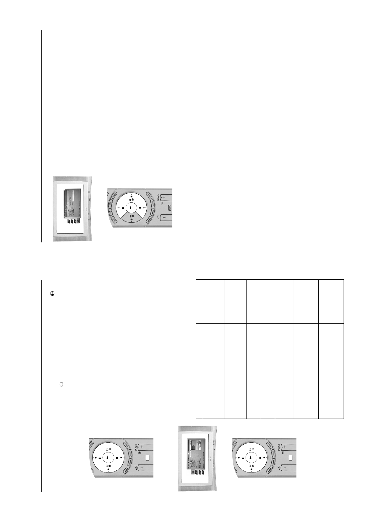
Viewing Memory Stick pictures
A ‘Memory Stick’* is a new recording medium with a data capacity that exceeds a
floppy disk. It is specially designed for exchanging and sharing digital data among
‘Memory Stick’ compatible products. Use ‘Memory Stick’ to display JPEG pictures
(DCF version 1.0 format)** individually or as a slideshow presentation on the TV
screen. Because it is removable, ‘Memory Stick’ can also be used for external data
storage.
Inserting a ‘Memory Stick’
Insert a memory stick into the front control panel of the TV set until it clicks into the
connector. The v symbol must be facing forwards. The red ligh t flas he s ind ic ati ng tha t
the memory stick contents are being read.
Removing a ‘Memory Stick’
Confirm that the red light is off. Do not pull the memor y stick. You must push the
memory stick and then release. The memory stick will spring out.
Note:
* Data stored on a ‘Memory Stick’ may become damaged or erased if you remove the
‘Memory Stick’ when it is reading or writing data.
The ‘Memory Stick’ menu
The ‘Memory Stick’ menu is displayed automatically when you insert the memory stick
into your TV set. Alternatively, if there is a memory stick already inserted, press the
MEMORY STICK button on the remote control to display the menu screen. There are
3 options available, namely ‘Index’, ‘Slideshow’ and ‘Setup’.
Notes:
* Memory Stick’ and the logo are trademarks of Sony Corporation.
** DCF (Design rules for Camera File systems) is a st andard file name format for digital still
cameras, DV camcorders etc. It is supported by SONY and other manufacturers.
been found press either OK to store or v to continue searching.
Press v to select AV1, AV2, AV3, or AV4 depending on which socket you have
(c) For external input sources (EXT):
connected your equipment to. Press OK to store.
Naming a channel
Names for channels are usually taken automatically from Teletext (if available). This
name is display ed briefly on scre en when the chan nel is s elect ed. The ‘LABEL’ option in
the ‘Manual Programme Pres et’ menu allows you to assign a name of your choice up to
5 characters or numbers. With the ‘Manual Programme Preset’ option highlighted,
press b to enter the ‘Manual Programme Preset’ menu. Press v or V to highlight the
channel number you require. Press b repeatedly to select the LABEL column. Press v
or V to select the first character. Press b to confirm this character. Select the other
characters in the same way. After selecting all required characters, press OK to store.
Skipping a channel
The ‘SKIP’ option in the ‘Manual Programme Preset’ menu all ows you to s kip unused
channel positions when selecting channels with the PROG+/- buttons. However, you
Programme Preset’ menu. Press v or V to highlight the channel number you require.
can still select skipped channel s by using the numbered buttons on the remote control.
With the ‘Manual Programme Prese t’ option highlighted, press b to enter the ‘Manual
Press b to select the SKIP column. Press v to select On (select Off to remove the SKIP
feature). Press OK to store.
frequency:
methods:
Manual Programme Preset menu
(for analogue channels only)
To check which mode you are in, press the button on the remote control. If you are
watching a digital programme, an Info display appears on screen providing brief details
for the current and next programme. If this happens, press the DIGITAL/ button on
the remote control to switch to analogue channels.
The ‘Manual Programme Preset’ option in the ‘Manual Set Up’ menu allows you to
manually tune in channels. With the ‘Manual Program me Preset’ option highlighted,
press b to enter the ‘Manual Programme Preset’ menu. Press v or V to highlight the
channel you wish to tune. Press b twice to select the SYS column. Press v or V to
select the TV broadcast system (Choose I for TV broadcasts or EXT for an external
input source). Press b to confirm and select the CH column. Press v or V to select the
(a) If you know the channel number of the TV broadcast, the VCR test signal or the
channel tuning (C for terrestrial channels, S for cable channels or F for direct frequency
input). Press b to confirm. You now need to tune the channel by one of the following
Press v to select SEARCH. The TV set automatically searches for the next
Press the numbered b u ttons on the remo te cont rol to ent er the chann el nu mber.
Press OK to store.
(b) If you do not know the channel number:
TV menu system
- 12 -
28
Page 13
M
E
MO
R
Y
S
TIC
K
DIGITAL
OK
VTR
T
V
D
VD
M
E
M
O
R
Y
STICK
D
IG
IT
A
L
V
T
R
TV
D
V
D
OK
Connecting other equipment
MODE
1
4
7
3
6
9
2
5
8
8
0
VTR
T
V
DVD
Find the 3 digit code for your brand from the list below. If your brand has more than one code
allocated to it, make a note of the first code only at this stage.2.Press the MODE button on the remote control until e ither th e VCR g reen l ight or the DVD green
light is illuminated.3.With the required green light illuminated, press and hold down the YELLOW button for
approximately 6 seconds, until the light starts to flash.4.Using the numbered buttons, enter the 3 dig it code for your DVD or VCR. Once a correct
number has been entered, all three green lights will illuminate momentarily.5.T urn on y our DVD or VCR and check that the remote control oper ates th e mai n funct ions . If no t,
repeat steps 2 - 4 and enter the next 3 digit code allocated to your brand of VCR or DVD.6.When you wish to use the rem ote c ontro l t o op erate the TV again, press the MODE butt on u nti l
37
the TV green light illuminates. Don’t forget to select VCR or DVD using the MODE button every
Note: The brand codes you set may be lost if weak batteries are not replaced immediat ely. Should this
happen, use the above procedure to reset the code. A small label has been attached to the inside of the
battery cover for you to make a note of your brand codes.
Not all brands and models of DVDs or VCRs are covered in this list. However, Sony will endeavour to
time you wish to operate that equipment with this remote control.
update the software periodically, so please refer to the code table provided with your remote control.
Memory Stick operation
1.
Remote control operation for VCR and DVD players
This remote control has been configured to operate not only Sony DVDs and VCRs but also those made by other manufacturers. To
operate other makes of DVD and VCR using this remote control, complete the following procedure:
VCR Brand List DVD Brand List
Brand Code Brand Code
SONY (VHS) 301, 302, 303, 309 SONY 001
SONY (BETA) 301, 302, 303, 309 AIWA 021
SONY (DVD) 304, 305, 306 DENON 018, 027, 020, 002
AIWA 325, 331, 351 GRUNDIG 009, 028, 023, 024, 016. 003
AKAI 326, 329, 330 HITACHI 025, 026, 015, 004
DAEWOO 342, 343 JVC 006, 017
GRUNDIG 358, 355, 360, 361, 320, 351 KENWOOD 008
HITACHI 327, 333, 334 LG 015, 014
JVC 314, 315, 322, 3 44, 3 52, 353, LOEWE 009, 028, 023, 024, 016. 003
LG 332, 338 MATSUI 013, 016
LOEWE 358, 355, 360, 361, 320, 351 ONKYO 022
MATSUI 356, 357 PANASONIC 018, 027, 020, 002
ORION 3 28 PHILIPS 009, 028, 023, 024, 016. 003
PANASONIC 321, 323 PIONEER 004
PHILIPS 311, 312, 31 3, 3 16, 3 17, 318, SAMSUNG 0 11 , 014
SAMSUNG 339, 340, 341, 345 SANYO 007
SANYO 335, 336 SHARP 019, 027
SHARP 324 THOMSON 012
THOMSON 319, 350 TOSHIBA 003
TOSHIBA 337 YAMAHA 018, 027, 020, 002
31
then press the
‘Page +’
time. If your required picture is not visible, highlight
OK button to view the next set of pictures. Press the v, V, B or b buttons to
select your desired picture then press the OK button to vi ew.
‘Memory Stick’ menu on the TV screen.
Press the MEMORY STICK button on the remote control to display the
Press the V or v button to highlight ‘Index’ then press the OK button to
Press the v, V, B or b b utton s to high light th e requir ed pi cture , then press th e
OK button to display the picture fully on the TV screen.
display the ‘Memory Stick Index’ screen.
1.
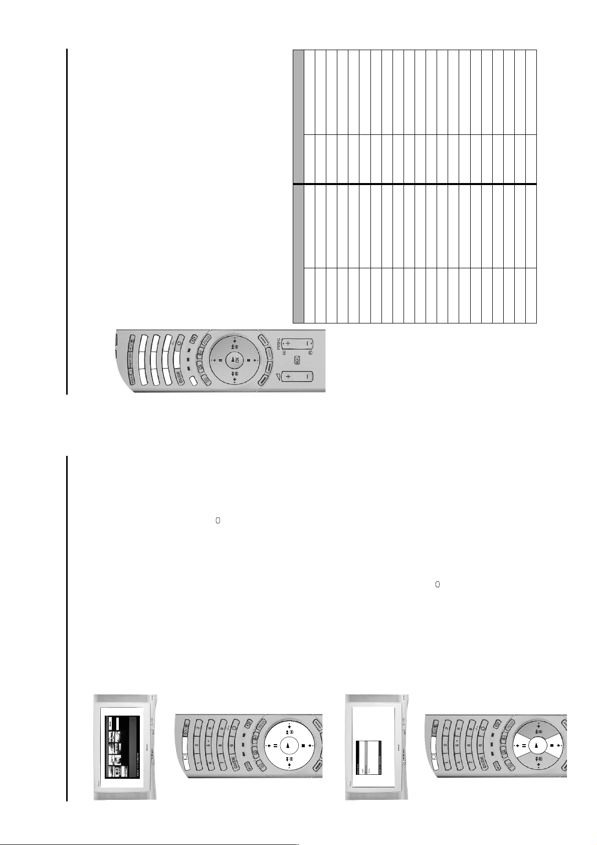
Index
This feature enables you to view on screen the JPEG DCF format pictures from your
memory stick.
Memory Stick Index
2.
Page +
Page 1/3
Note: Only a limited number of pictures can be displayed on the Index screen at one
3.
return to normal TV operation.
Use the v, V, B or b buttons to highlight ‘Back’. Press the OK button to return
to the ‘Memory Stick’ menu or press the DIGITAL/ button at any time to
4.
Slideshow
Press the MEMORY STICK button on your remote control to display the
‘Memory Stick’ menu on the TV screen.
1.
This feature allows you to display all the memory stick pictures as a slideshow
presentation on the TV screen.
Press the V or v button to highlight Slideshow.3.Press the OK button to start the slideshow. (To change the length of time an
2.
image is displayed refer to the ‘Setup’ section on the following page.)
Press the OK button during the slideshow to return to the ‘Memory Stick’
menu. Press the DIGITAL/ button to return to normal TV operation.
4.
- 13 -
Page 14
4
Additional Information
/
39
button on the front of the TV. If the
indicator is on press the button on the remote control.
brightness, picture and colour levels.
‘Manually tuning analogue signals’ instructions of this
manual to tune in available analogue channels, then contact
local installer to find out when digital transmissions begin in
your area.
should be pointing your aerial at.
programmes.
• Check aerial connection
• Plug in the TV
• Pr ess the
• Tune in all the Analogue channels available using the
• Contact a local installer to find out which transmitter you
other equipment).
• Change your aerial to cover the channels used by digital
• Ens ure aer ial is correctly aligned to transmitter.
• Ensure aerial is is plugged directly into the TV (not through
• Upgrade to a higher gain aerial.
• Subs cr ibe to pay-per-view broadcaster.
• See ‘Skipping a programme’ section.
• See ‘Re-arranging your channels’ section.
• Do not open the cabinet, refer to qualified personnel.
• Contact nearest SONY Service Centre.
• Will clear when Timer Recording stops.
the remote control.
is displayed on screen.
• If is displayed on the screen, press the button on
setting.
• Press the button repeatedly until the RGB symbol
• Switch off all additionally connected equipment.
Troubleshooting
Here are some simple solutions to problems which may affect the picture and sound.
• Picture preset level adjustment • Select ‘Picture Adjustment’ menu then adjust adjust the
• TV in standby.
• Aerial disconnected.
• No digtal transmission in your area.
Poor or no picture (screen is
Problem Possible causes Solutions
No picture, no sound. • Power off
dark), but good sound.
No picture on any channel after
digital tuning.
transmitter you are currently using.
• No digital transmissions from the
• Unsuitable aerial. • Weak signal.
channel.
Some channels are blank. • Scrambled or subscription-only
• Programme used only for data (no
picture or sound).
• Programme not being transmitted.
(regular flash).
• Digital mode Timer Record active
Standby indicator flashing. • Fault (irregular flash)
RGB video source.
• Colour level setting. • Select ‘Picture Adjustment’ menu then adjust the colour
Good picture, no sound • Volume control. • Press the + button on the remote control.
Poor picture quality • Wrong external mode selected for an
No colour on colour
programmes
switched off.
• Batteries low. • Replace batteries.
• Inputs from external equipment not
Remote control does not
function
Distorted picture when
changing programmes or
Digital HelpLine on 0870 600 1717.
selecting teletext
• If you continue to have these problems, have your TV serviced by qualified personnel or you can contact the Sony UK
• NEVER open the casing yourself.
21-pin Euro connector (CENELEC standard) including audio/video
21-pin Euro connector (CENELEC standard) including audio/video
input, RGB input, TV audio/video output
input, S-video input, selectable audio/video output.
3
s
3/
Conditional Access Module
- 14 -
input, RGB input, TV audio/video output.
1
NTSC 3.58, 4.43 (only Video In)
MPEG-2 MP@ML
KV-36NX200 FD Trinitron Approx. 91cm
Subwoofer 1x30W (music power), 1x15W (RMS)
KV-36NX200 182W (1w standby)
KV-36NX200 Approx. 1010 x 645 x 607mm
TV System I/DVB-T
Colour System PAL
Channel Coverage UHF: B21 - B69
Picture Tube KV-32NX200 FD Trinitron Approx. 82cm
Sound Output Left/Right: 2x20W (music power), 2x10W (RMS)
Power Consumption KV-32NX200 154W (1w standby)
Dimensions (w x h x d) KV-32NX200 Approx. 910 x 445.5 x 590mm
Weight KV-32NX200 Approx. 67kg
Additional Information
Specifications
KV-36NX200 Approx. 87kg
2
Rear Terminals 21-pin Euro connector (CENELEC standard) including audio/video
RF In
Video input - phono jack
Audio output - RCA phono jacks
Front Terminals
Headphones jack - minijack stereo
Audio inputs - phono jacks
S video input - 4 pin DIN
4
4
s
RM-939 remote control (1)
IEC designated size AA (R6) battery (2)
RF Loopthrough cable
Accessories Supplied
Design and specification are subject to change without notice
38
Page 15
SECTION 2 DISASSEMBLY
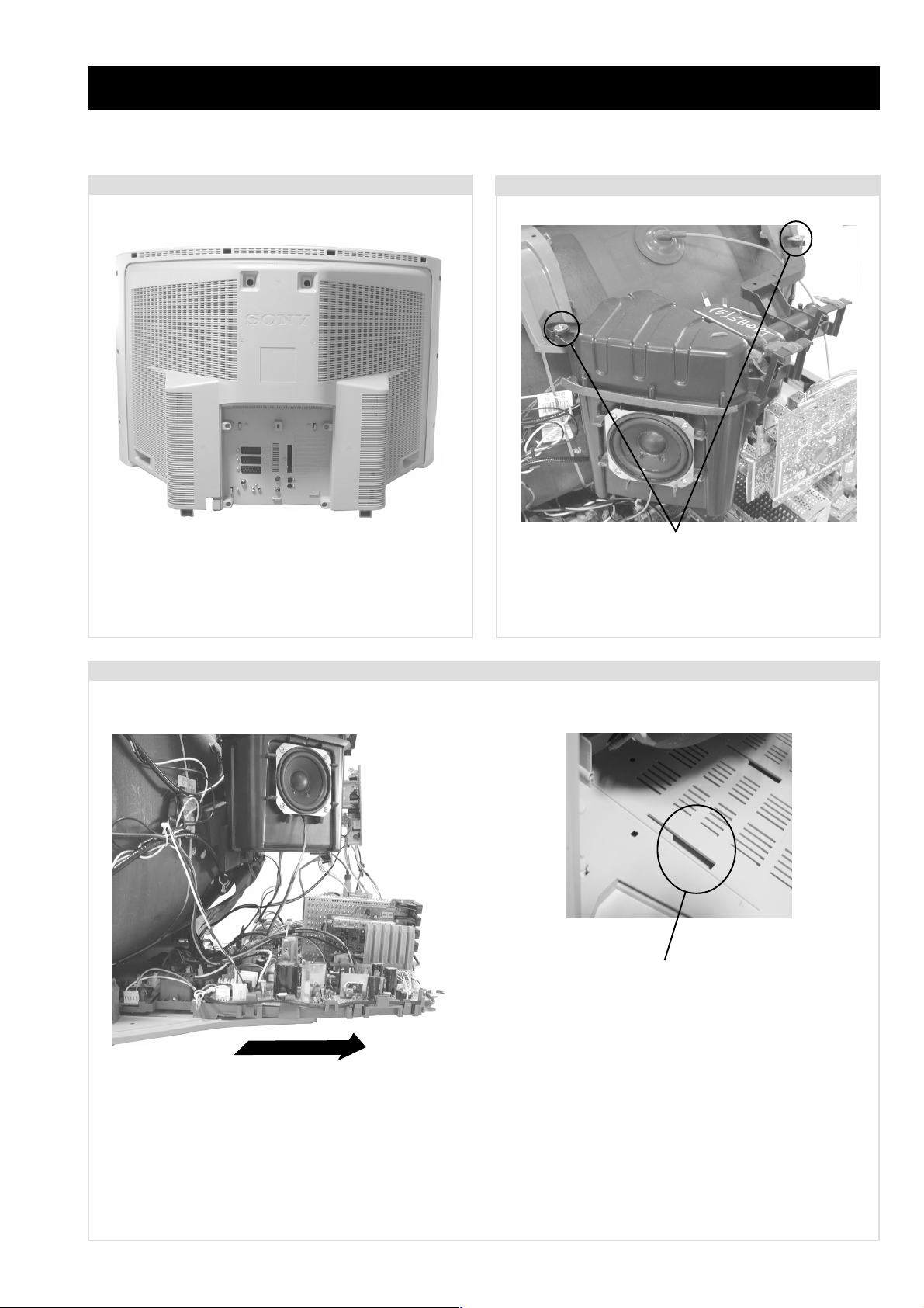
2-1. Rear Cover Removal
=>
=>
=>
=>
=>
=>
=>
=>
=>
Remove the rear cover fixing screws indicated and pull the
rear cover backwards away from the set.
=>
=>
=>
2-2. Speaker Box Removal
=>
=>
=>
=>
Screws
T o remo ve the speak er box assembly remov e the two scre ws
circled and unplug the speaker lead from connector CN1202
on the ‘A’ board. The assembly can then be lifted gently
away from its supporting arms.
2-3. Chassis Removal and Refitting
T o remove lift the main bracket rear slightly and slide the
chassis away from the beznet. Ensure that the interconnecting
leads are released from their purse locks to prevent damage
being caused.
When refitting the chassis ensure that the main bracket is
located in the beznet guide slots before sliding the chassis
forwards. Refit the inter-connecting leads in their respective
purse locks.
- 15 -
Page 16
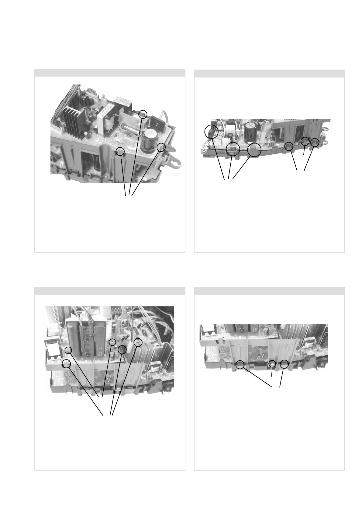
2-4. G1 Board Removal
2-5. G Board Removal
Screw
Clips
Clips
Clips
T o remove the G1 board release the three clips circled and
ease the board gently away from the support bracket.
2-6. D2 Board Removal
T o remov e the G Board first remo ve the G1 bracket by
removing the screw circled and releasing the four clips (two
on each side of the bracket).
The G Board can the be removed by releasing the clips circled
and easing the board gently away from the support bracket.
2-7. D1 Board Removal
Screws
Clips
T o remov e the D2 board remove the tw o scre ws circled,
release the clips circled and ease the board gently away from
the support bracket.
Screw
Clips
T o remov e the D1 board first remo ve the D2 bracket by
removing the two screws (one on each side of the bracket)
and releasing the four clips (two on each side of the bracket).
The D1 board can then be removed using the same method as
the G board.
- 16 -
Page 17

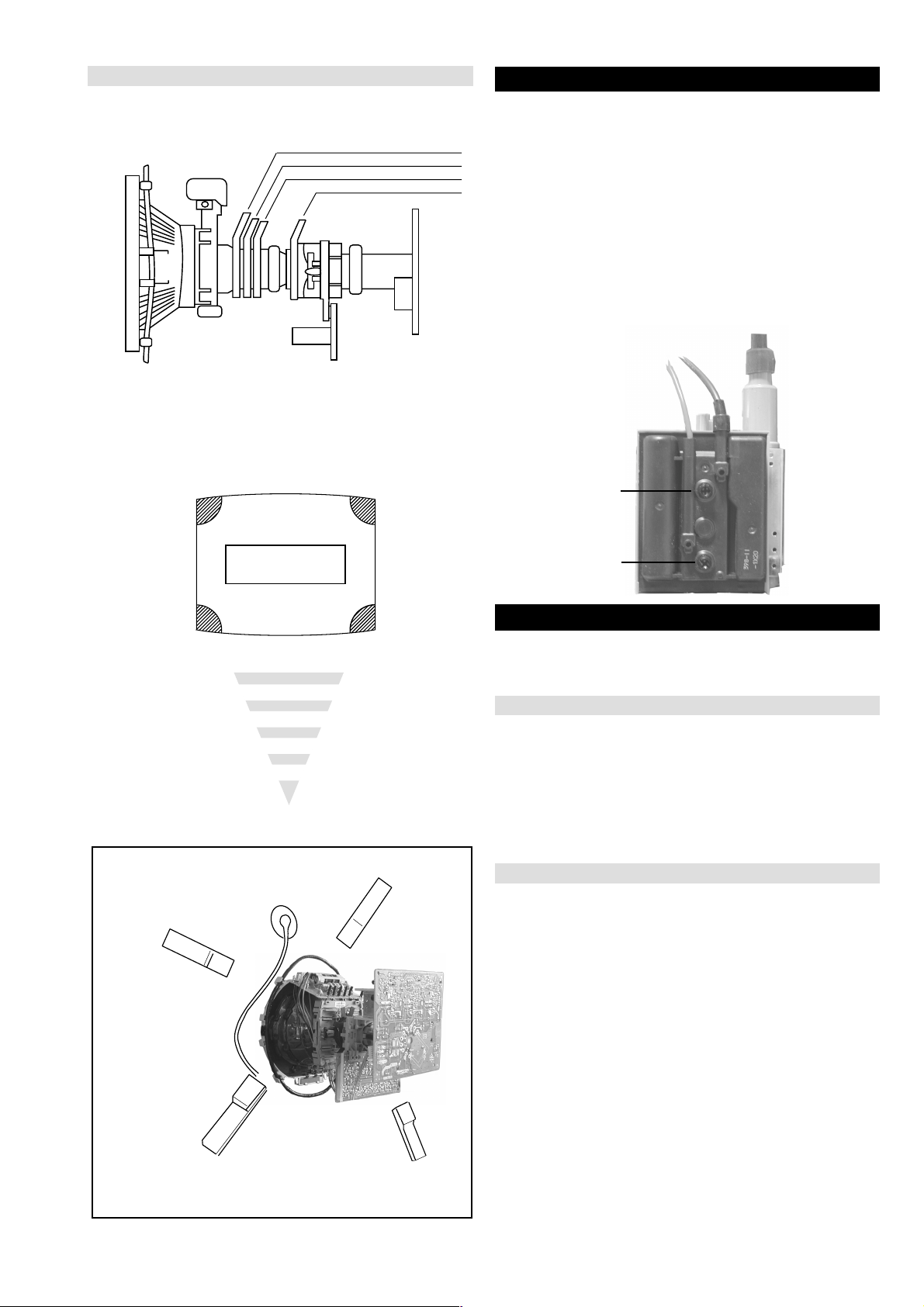
2-8. Service Position
T o place the chassis in the service position, remove the
speaker assembly box (see 2-2.), remove the G1 and D2
brackets and position on the side of the main bracket as shown
above. Insert the main bracket firmly into the T-slot located on
the left corner of the beznet as indicated (see inset). T o gain
access to the underside of the boards follow the instructions
on page 19. [Removal and Replacement of the main bracket
bottom plates].
2-9. Wire Dressing 1
T o avoid damage to the ground interconnecting leads from the
sharp edges of the heatsink they must be dressed as shown
above between the rear of the heatsink and the tuner .
2-10. Wire Dressing 2
The sheathed end of the ground connecting lead must be
plugged into the F3 board to avoid the possibility of the AC
mains power touching ground.
2-11. Wire Dressing 3
20mm
20mm
Ensure that wires do not touch heatsinks and high temperature
hotspots. All wires must be k ept at a minimum distance of
20mm away from the EHT lead
- 17 -
Page 18
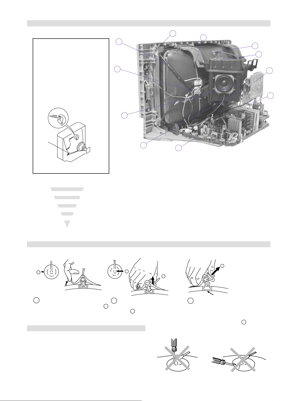
2-12. Picture Tube Removal
WARNING:
BEFORE REMOVING
THE ANODE CAP
High voltage remains in the CRT even
after the power is disconnected. To
avoid electric shock, discharge CRT
before attempting to remove the anode
cap. Short between anode and CRT
coated earth ground strap.
Coated Earth
Ground Strap
11
9
8
7
6
5
10
2
1
4
3
1. Remove Speaker Box assembly.
2. Discharge the anode of the CRT and remov e the anode cap.
3. Unplug all interconnecting leads from the Deflection yoke, neck
assy, de gaussing coils and CRT grounding strap.
4. Remove the C1 Board from the CR T .
5. Remove the chassis assembly.
6. Loosen the Neck assembly fixing screw and remove.
7. Loosen the Deflection yoke fixing screw and remove.
8. Place the set with the CRT f ace down on a cushion and remo ve
the Degaussing Coil holders.
9. Remove the Degaussing Coils.
10. Remove the CR T grounding strap and spring tensioners.
11. Unscrew the four CRT f ixing scre ws [ located on each CRT
corner ] and remove the CR T .
[T ake care not to handle the CR T by the neck.]
Removal of the Anode-Cap
REMOVAL PROCEDURE.
a
1
Turn up one side of the rubber cap in
the direction indicated by the arrow a
b
2 Using a thumb pull up the rubber cap
firmly in the direction indicated by the
arrow b
How to handle the Anode-Cap
1. To prevent damaging the surface of the anode-cap do not use
sharp materials.
2. Do not apply too great a pressure on the rubber, as this may cause
damage to the anode connector.
3. A metal fitting called a shatter hook terminal is fitted inside the
rubber cap.
4. Do not turn the rubber foot over excessively, this may cause
damage if the shatter hook sticks out.
c
b
Anode button
3 When one side of the rubber cap is
separated from the anode button, the
anode-cap can be removed by turning
up the rubber cap and pulling it up in
the direction of the arrow c
- 18 -
Page 19

Catch
For safety reasons, on no account should the plates be removed
and not refitted after servicing.
Because the plates differ in size it is important that the correct plates are refitted in their original
location.
Please note that the plates need to be rotated 180 degrees from their cut position to allow the
(2) REFITTING THE PLATES
tabs to be fitted into their catch positions.
Tab
REMOV AL AND REPLA CEMENT OF THE MAIN-BRACKET
BOTT OM PLA TES.
Only remove the necessary plate to gain access to the printed wiring board.
In the event of servicing being required to the solder side of the A, D1 or G printed wiring
boards, the bottom plates fitted to the main chassis bracket require to be removed.
This is performed by cutting the gates with a sharp wire cutter at the locations indicated by the
arrows.
(1) REMOVING THE PLATES
Note : There are 3 plates fitted to the main bracket and secured by 3 gates.
- 19 -
Page 20
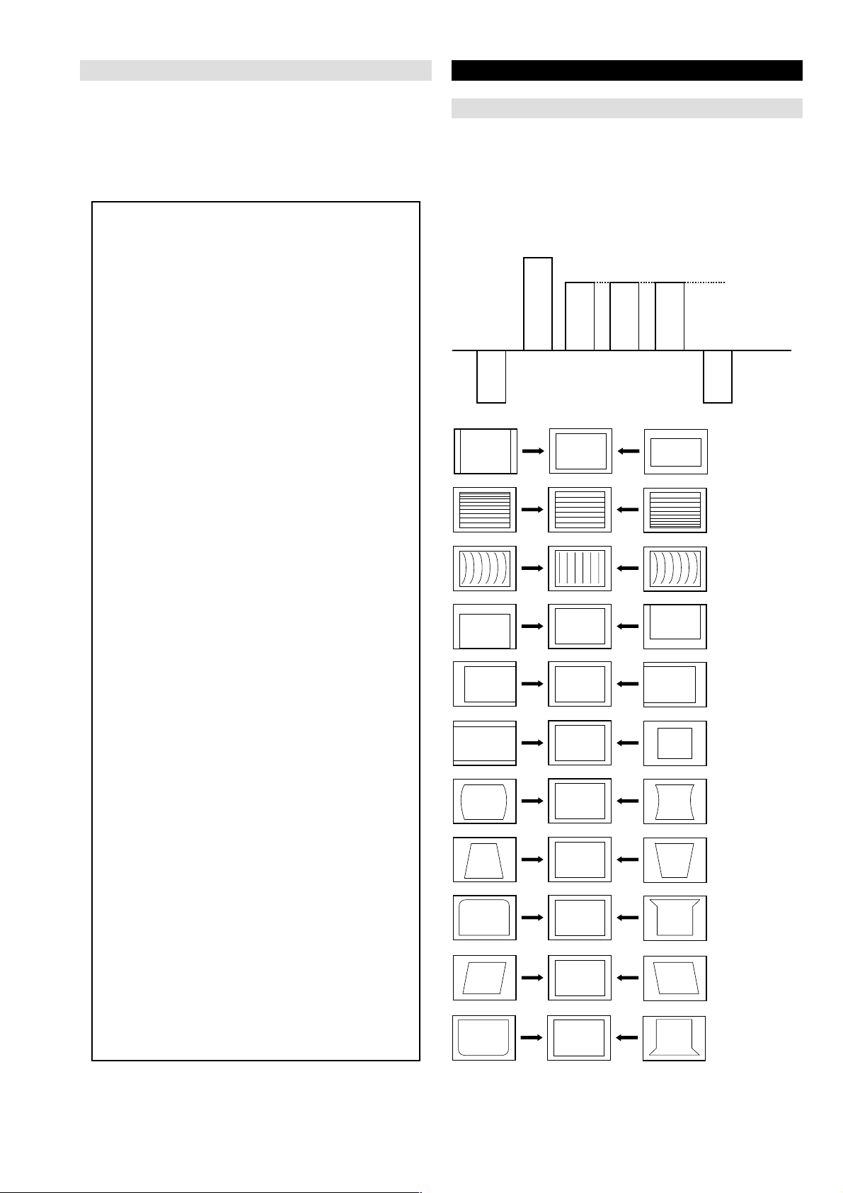
SECTION 3 SET-UP ADJUSTMENTS
Neck assy
Align the edge
of the neck assy between
the G2 grid and G1 grid.
G2
G1
+
• When complete readjustment is necessary or a new picture tube
is installed, carry out the following adjustments.
• Unless there are specific instructions to the contrary, carry out
these adjustments with the rated power supply .
• Unless there are specific instructions to the contrary, set the
controls and switches to the following settings :
Contrast .................................. normal
Brightness .................................. normal
3-1. Beam Landing
Preparation :
1. In order to reduce the influence of geomagnetism on the set’s
picture tube, face it in an easterly or westerly direction.
2. Switch on the TV set’s power and degauss with a degausser.
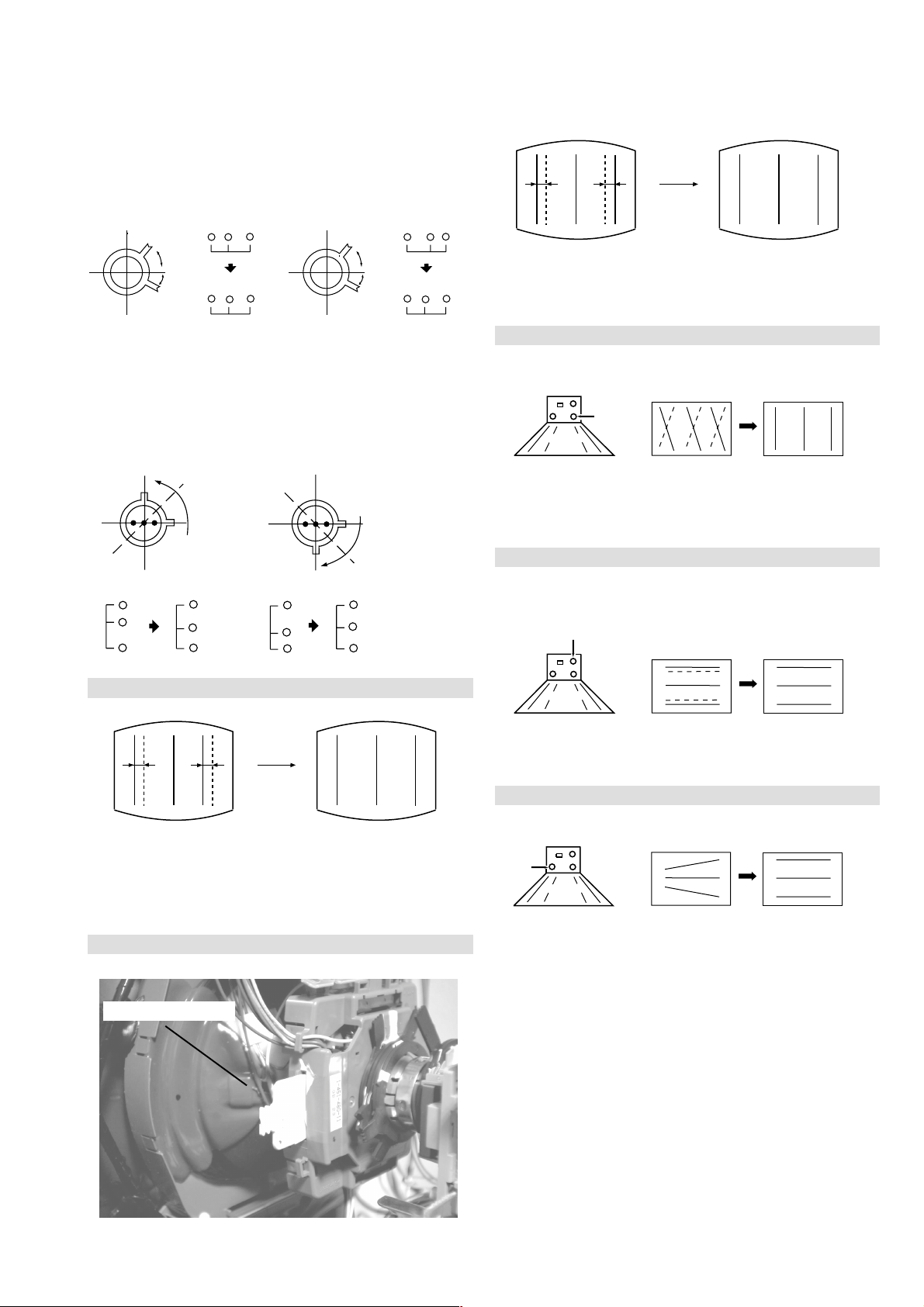
(1) Adjustment of Correction Magnet for Y-Splitting Axis.
1. Input a crosshatch signal from the pattern generator .
2. Set the Picture control to minimum and confirm that the
Brightness control is set to normal.
3. Position the neck assembly as indicated in Fig.3-3.
4. Loosen the deflection yoke fixing scre w .
5. Move the deflection yoke as far forward as is possible.
6. Adjust the upper and lower pin symmetrically by opening or
closing the Y -splitting axis correction magnets located on the
neck assembly . [See Fig 3-2]
7. Return the deflection yoke to its original position and re-tighten
its fixing screw.
Fig.3-1
Y-splitting axis correction magnet
Carry out the adjustments in the following order :
3-1. Beam Landing and Geometry.
3-2. Convergence.
3-3. Focus.
3-4. White Balance.
Note : Test equipment required.
1. Color bar/pattern generator .
2. Degausser.
3. Oscilloscope.
4. Digital multimeter.
(2) Landing and Geometry
Note : Before carrying out the following adjustments adjust the
magnets as indicated on page 21 [See Fig.3-4].
1. Input a crosshatch signal from the signal generator .
2. Rough-adjust the focus and horizontal convergence.
3. Switch from the crosshatch pattern to an all-red pattern.
4. Move the deflection yoke backwards and adjust with the purity
magnet so that the red is at the centre and it aligns
symmetrically [See Fig.3-5].
5. Move the deflection yoke forward to the point where the entire
screen just becomes red [Mark its position].
6. Move the deflection yoke further forward until the screen just
changes colour at the edges. [Mark its position].
7. Position the deflection yoke between the two marks indicated
above.
8. Input a crosshatch pattern from the pattern generator and rotate
the deflection yoke so that the horizontal lines are parallel with
the top and bottom of the screen.
9. When the position of the deflection yoke has been determined,
fasten it with its fixing screw.
10. Once dy rotation and swing left and right for h linearity is ok on
cross hatch pattern, insert dy wedges. [See Fig.3-6].
11. Switch the pattern generator to green then blue and confirm the
purity .
12. If the beam does not land correctly in all the corners of the
screen, use disk magnets to correct it. [Confirm the corner
landing forgreen and blue].
13. Re-check geometry for landing magnet effect. Adjust using
deflection menu. [TT Mode].
Fig.3-2
Caution :
High voltages are present on the Deflection yoke terminals - take care
when handling the Deflection yoke whilst carrying out
adjustments.
Fig.3-3
- 20 -
Page 21
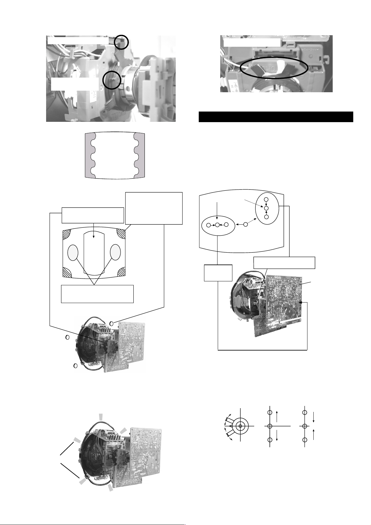
Fig.3-4
B
G
R
B
G
R
Purity magnets
Align pips on
each magnet
Align both Purity
magnets to the vertical
position
Purity control magnets
3-2. Con vergence
(1) Screen centre convergence [Static convergence]
Fig.3-5
GREEN
RED
BLUE
Disk magnets or
rotatable disk
Purity control corrects
this area
magnets correct
these areas (a-d)
ab
c
Deflection yoke positioning
corrects these areas
d
1. Input a dot pattern signal from the pattern generator .
2. Normalize the picture setting.
3. [Moving v ertically], adjust the V.STAT magnet so that the
vertical red, green and blue dots coincide at the centre of the
screen.
Center dot
R
G
B
H STAT
convergence
control
R
G
B
V.STAT Vertical Static Magnet
C1 Board
RV9001 (H STAT)
H STAT Convergence
(on mount side)
Disk Magnets
Fig.3-6
5 Wedges
required
By opening or closing the V.STAT magnet, the red green and
blue dots move in the direction indicated below .
Note: Do not adjust the H.STAT by rotating the V.ST AT
magnets as this can affect the focus setting.
- 21 -
Page 22
4. Correction for HMC [Horizontal mis-con vergence] and VMC
+
+
+
YCH VR
Deflection Yoke
+
+
+
TLV VR
Deflection Yoke
[V ertical mis-con ver gence] by using the BMC [Hexapole]
magnet.
a). HMC correction by BMC [Hexapole] magnet and movement of
the electron beam.
HMC correction(A) HMC correction(B)
A < B
RG B
A > B
RGB
HTIL correction can be performed by adding a THL correction
assembly to the Deflection yoke.
A = B
A B
RG B
A B
A = B
A B
RG B
A B
b). VMC correction by BMC [Hexapole] magnet and movement of
the electron beam.
VMC correction(A) VMC correction(B)
C < D
C
D
C = D C > D C = D
R
G
B
R
C
G
D
B
C
D
R
G
B
R
C
G
D
B
HAMP Adjustment
YCH Adjustment
TL V Adjustment
Adjust the HAMP using HAMPL and HAMPR registers in the
Dynamic Convergence section of the service menu.
HTIL Adjustment
THL Correction assy
H-TRAP Adjustment
+
+
HTRAP VR
+
Deflection Yoke
The H-TRAP should not be adjusted unless absolutely necessary as it
affects the TLV settings.
- 22 -
Page 23
Layout of each control
Purity magnet
BMC (Hexaploe) magnet
V STAT convergence magnet
Y-splitting axis correction magnet
Note : If you are unable to adjust the corner convergence properly ,
this can be corrected with the use of permalloy magnets.
a
b
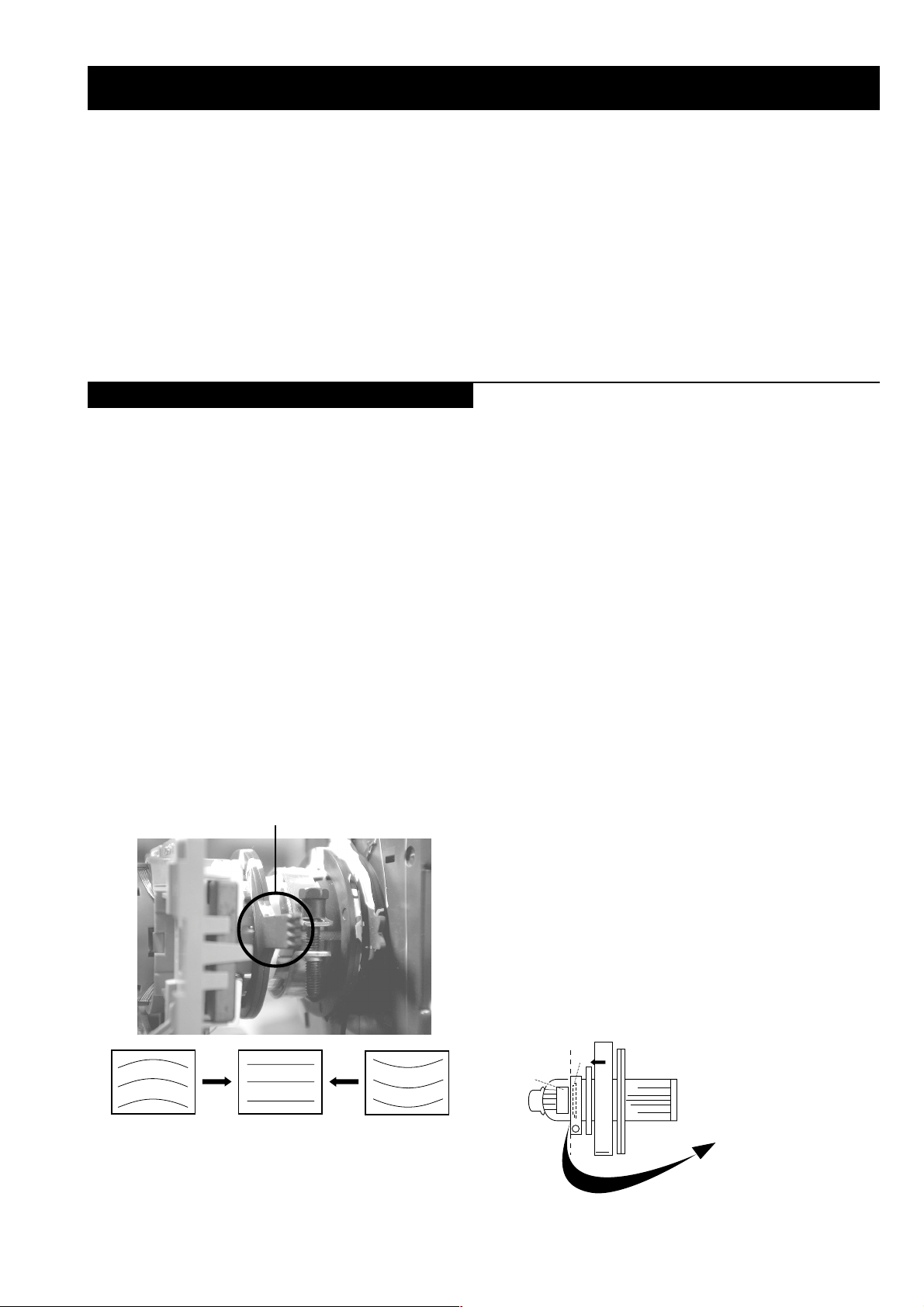
3-3. Focus Adjustment
1. Receiv e a cross hatch pattern from a video generator .
2. Adjust the focus control located on the flyback transformer to
the best level at the centre of the screen.
3. Check left and right x-axis vertical line thickness and adjust to
make them as thin as possible.
4. Considering x-axis and centre, adjust to make uniform.
5. If no cross hatch signal is possible, follow the next three steps.
6. Receive a television broadcast signal.
7. Normalize the picture setting.
8. Adjust the focus control located on the flyback transformer to
obtain the best focus at the centre of the screen.
Bring only the centre area of the screen into focus, the magentaring appears on the screen. In this case, adjust the focus to
optimize the screen uniformly.
Focus
a-d: screen-corner
convergence defect
c
Install the permalloy assembly
for the area that needs correcting.
b
Permalloy Assy
X-4387-214-1.
d
Convergence adjustment with permalloy
Screen
d
3-4. Screen (G2), White Balance
[Adjustment in the service mode using the remote
commander]
G2 adjustment
1. Input a dot signal from the pattern generator .
2. Set the Picture, Brightness and Colour to minimum.
3. Apply 165V DC from an external power supply to the R, G
and B cathodes of the CRT.
4. Whilst watching the picture, adjust the G2 control [SCREEN]
located on the flyback transformer to the point just before the
flyback return lines disappear.
a
White balance adjustment for TV mode
1. Input an all-white signal from the pattern generator .
2. Program the Remote Commander for operation in Service Mode.
[See Page 24].
3. Enter into the ‘Service Mode’ by pressing ‘VIDEO’ button twice
and ‘MENU’ on the Service Commander.
4. Select ‘Device Register Setting’ from the on screen menu display
and press ‘Right Arrow’.
5. Select ‘Backend’ from the on screen menu display and press
‘Right Arrow’.
6. Set the ‘Contrast’ to MAX.
7. Set the ‘R-Drive’ to 45.
8. Adjust the ‘G-Drive’ and the ‘B-Drive’ so that the white
balance becomes optimum.
9. Press the ‘OK’ button to write the data for each item.
10. Set the ‘Contrast’ to MIN.
11. Set the ‘R-Cutoff’ to 35.
c
12. Adjust the ‘G-Cutoff’, and the ‘B-Cutoff’ with the left and
right buttons on the remote commander so that the white
balance becomes optimum.
13. Press the ‘OK’ button to write the data for each item.
- 23 -
Page 24

SECTION 4 CIRCUIT ADJUSTMENTS
4-1. Electrical Adjustments
Service adjustments to this model can be performed using the
supplied remote Commander RM-939.
Programming the Remote Commander for Operation in Service Mode
1. Press the VCR/TV/DVD button until the
TV LED lights.
2. Press and hold the yellow button for
approx. 5 seconds until the TV LED
flashes quickly .
3. Press 99999. All three LED’s should light.
The remote commander is now set to Service Mode.
4. T o return the remote commander to normal operation mode
repeat steps 1. and 2. then press 00000. All three LED’s
should light.
The remote commander is now set to normal mode.
Setting the TV into Service Mode
1. Program the remote commander for operation in Service
Mode as described above.
2. T urn on the TV main po wer switch.
3. Press the video standby button on the remote
commander twice.
‘TT ’ will appear in the upper right corner of the screen.
Other status information will also be displayed.
Initialising Menu
gnisilaitinI
gnitteSledoM
gnitteSnoitanitseD
gnitteScisaB
gnitteSerutaeF
:tceleS:unemtxeN
Model Setting
The menu contains a list with all the available models of this software
to set up the TV set in an easy way . The selection of a model is setting
data for its features and hardware resources which cannot be detected
by the automatic power on H/W detection as well as a special model
byte to get an unique model identification for models which cannot be
differed by features and hardware resources (e.g. KD-32NS200 and
KD-36NX200)
Before data is set, the user will be asked if he really wants to set a
new model. If the user agrees, automatically the destination setting
menu is shown.
gnitteSledoM
002XN23-DK
002SN23-DK
002XN63-DK
002SN63-DK
eseR
t
4. Press ‘MENU’ on the remote commander twice to obtain the
following menu on the screen.
3B096V,200212nuJ,D6EAecivreS
gnisilaitinI
seciveDteseR
gnirotinoM
gnitteSretsigeReciveD
.tnemtsujdAlaicepS
:uneMtxeN:tceleS
5. Move to the corresponding adjustment item using the
up or down arrow b uttons on the Remote Commander.
6. Press the right arrow button to enter into the required menu item.
7. Press the ‘Menu’ button on the Remote Commander to quit the
Service Mode when all adjustments have been completed.
Note :
· After carrying out the service adjustments, to prevent the
customer accessing the ‘Service Menu’ switch the TV set
OFF and then ON.
· Certain menu items are only available in production mode.
KCALBytimrofnoCoN=
NEERGledoMelbitapmoC=
DERatadllarofytimrofnoC=
Table.4-1
Indication of Model Compatibility.
Black:
If any data does not match to specific model, the model name is
displayed in black.
Green:
All data which is checked by model setting menu concurs to model
except model byte.
Red:
All data which is checked by model setting menu concurs to model
including model byte.
Note:
After selecting a model, it may be necessary to reset some devices to
get the correct data. (Treble/Bass Offset of Sound, deflection
adjustments, ...)
- 24 -
Page 25

Basic Setting
hctiwSoediV/oiduA
gnittescisaB
oNrcseDniMxaMataD
1G/B.sySFFONONO
2K/D.sySFFONONO
3L.sySFFONOFFO
4)KU(I.sySFFONOFFO
5)LRI(I.sySFFONOFFO
6noitpo.taNTXT143
7TRC9:61FFONOFFO
8refoow-buSFFONONO
9yb-dnatsotuAFFONONO
01retlif-bmoCFFONONO
11tedCYotuAFFONONO
21tedbmocotuAFFONONO
31elbaliavA2VAFFONONO
41elbaliavA3VAFFONONO
51elbaliavA4VAFFONONO
61elbaliavA5VAFFONONO
71epaTMACESFFONOFFO
81etuMdnuoS1VAFFONONO
Table.4-2
Feature Setting
gnitteserutaeF
oNrcseDniMxaMataD
1PAPFFONONO
2TAPFFONONO
3XEDNIFFONONO
4txeTeleTFFONONO
5GPEFFONONO
6beWeleTFFONOFFO
Table.4-3
Device Register Setting
dnekcaB
noitcelfeD
noitcelfeDtxE
ecnegrevnoCcimanyD
1redoceDruoloC
hctiwSoediV/oiduA
X-diM
X-diMLLPlanretxE
pihCyarrAetaG
dnuoS
RNlatigiD
Table.4-4
oNrcseDfeDniMxaMataD
11TUOVC0090
22TUOVC2090
3LRTC0OLFFOFFONOFFO
4LRTC1OLFFOFFONOFFO
51TUOCY2072
62TUOCY0070
7WSDCZFFOFFONOFFO
8ETUM3TUOAFFOFFONOFFO
91TUOA3073
012TUOA1071
11LEDPUORG6101361
213TUOA3073
31CLOV3TUOA4074
41FLOV3TUOA4074
51R/L3TUOA0030
61WS1DGNOFFONONO
71WS2DGNOFFONONO
811CNYS1011
912CNYS1011
021TNOCS3233
121OEDIV4034
221OIDUA0030
322TNOCS2232
422OEDIV4034
522OIDUA0030
623TNOCS2232
723OEDIV0030
823OIDUA1031
Table.4-5
oNrcseDfeDniMxaMataD
1egnaR3603636
2tatSV7103641
3tatsH1303613
4lpmaH0403633
5rpmaH0403633
6YpU1303613
7YwoL1303613
8lpuY5403654
9rpuY1303613
01lwolY1303613
11rwolY5403654
21lpuwobM1303613
31rpuwobM1303613
41lwolwobM1303613
51rwolwobM1303613
61lrtCProCTFFOFFONOFFO
71niProCpoT1303613
81lrtCProCBFFOFFONOFFO
91niProCtoB1303634
ecnegrevnoCcimanyD
- 25 -
Table.4-6
Page 26

1redoceDruoloC
)tnoc(1redoceDruoloC
oNrcseDfeDniMxaMataD
753EDOMDCFFOFFONOFFO
85SOPSH50515
95DNLRHTNFFOFFONOFFO
06VELECILS00130
16AERAPUFFOFFONOFFO
26NIHTPUFFOFFONOFFO
36J941XFFOFFONOFFO
46CTSMDFFOFFONOFFO
56TSNIFFOFFONOFFO
66LVLRPUNOFFONONO
76LVLSFOFFOFFONOFFO
86TSFOLSFFOFFONOFFO
9634MORF2032
07EDIWMORF2032
17SELTITRF2032
27LFPLNOFFONONO
37TESERWAFFOFFONOFFO
471EPOLSOTD005520
572EPOLSOTD005520
673EPOLSOTD005520
77CNACPUTES00510
87TNIV70517
97HPPLCTXE00360
08TUOTSETFFOFFONOFFO
18METSYSLOC80518
28EDOMBGR2032
38LESSYFFOFFONOFFO
48TEDNFFOFFONOFFO
58ECNAHNEV4074
68RNPFFOFFONOFFO
78QERFV0030
88BMOCNFFOFFONOFFO
98WSOTUAFFOFFONOFFO
09PARTMACESFFOFFONOFFO
19EDOMLLEBFFOFFONOFFO
29LIKMACES1031
39SOPDI2032
49DIWDINOFFONONO
59SYSLOC-EFFOFFONOFFO
69TUPNI-EFFOFFONOFFO
79KCOLH-EFFOFFONOFFO
89QERFV-ENOFFONONO
99SSW-EFFOFFONOFFO
001TESERTNIFFOFFONOFFO
101WS2CRS0030
201WSBMOC0030
301WSBGRFFOFFONOFFO
401KLBMACES1031
501LVLHNEV1031
601YLDCMCSFFOFFONOFFO
701DIMCSFFOFFONOFFO
801PDAMCSNOFFONONO
901EMITLLIKFFOFFONOFFO
011LVLLLIK2032
111SOPNK5075
211DIWDK70517
oNrcseDfeDniMxaMataD
1LESKLC0030
2KLCSYSNOFFONONO
3KLCPSD3033
4LEDFFOFFONOFFO
5LLPFFOFFONOFFO
6KLCFER1031
7LESDA0030
8NOPLCDFFOFFONOFFO
9FFOPLCFFOFFONOFFO
01LESBMOCFFOFFONOFFO
11FFOWAFFOFFONOFFO
21EDOMSYS00510
31MROFGIS2105121
41VELPILC0030
51RNY0030
61RNC0030
71EDOMKLB2032
81VELY2010552201
91VELC8010552801
02VELDSO0030
12SERDSOFFOFFONOFFO
22ROCPHS0030
322PUF1031
42JDAYLDCY60516
52DEPA0030
62NARTCD0030
72PHSBUS90519
82QEY3073
92OFPHSNOFFONONO
03KTADPA0030
13DLHDPA0030
23AERADPA0030
33SIHDPA0030
43CTRTCD0030
53CTPLCD0030
63SOPPLC70517
73QEC0030
83FPBC0030
93PARTFIDCFFOFFONOFFO
04CTPESSFFOFFONOFFO
14BMOCTNI0030
24EUHBUS70517
34NILRGPLC0030
44GPADAPLCFFOFFONOFFO
54ECILSSH0030
64ECILSSV1031
74CTPITS1031
84FPLCNYSNOFFONONO
94LIFCNYSFFOFFONOFFO
05NIAGCFA1031
15NIAGWOL1031
25PUDPSCFANOFFONONO
35OCWOLNOFFONONO
45OCHGIH0030
551EDOMDC0030
652EDOMDCFFOFFONOFFO
Table .4-7
Table.4-8
- 26 -
Page 27

dnekcaB
oNrcseDfeDniMxaMataD
1no-RNOFFONONO
2no-GNOFFONONO
3no-BNOFFONONO
4loc-D0030
5wS-bWFFOFFONOFFO
6L-ammaGFFOFFONOFFO
7tsartnoC0403604
8mottoB-KLB3033
9euH8203662
01sixA-ruoloC1031
11ruoloC1303613
21leveL-ITC2032
31ssenthgirB5203652
41lbA-S0030
51ssenprahS5203652
61leveL-ITL0030
71evirD-R5303653
81timiLP0030
91evirD-G1403614
02edoM-LBA0030
12evirD-B1403614
22edoM-ITC0030
32thgirBbuS60366
42ammaG1031
52ffotuC-R1303613
62edoM-ITL1031
72ffotuC-G7203672
82leveL-CIPD1031
92ffotuC-B1303613
03narT-CD1031
13tnoC-buS80518
23lvL-2BGRL80518
33lbA-P5105151
43HT-LBA00510
53P.ffO-BC2303645
63P.ffO-RC9203611
73S.ffO-BC4503636
83S.ffO-RC103636
93W-gnigAFFOFFONOFFO
04B-gnigAFFOFFONOFFO
14metsyS1031
24tesffo-Y70517
34leveL-MV1031
44OF.prahSNOFFONONO
54ffO-DCFFOFFONOFFO
64DC.prahS2032
74IF.prahS0030
84revO/erP2032
94roC-MV0030
05OF-MV2032
15timiL-MV3033
25yaleD-MV2032
35ruoloCbuS08-80
RNlatigiD
oNrcseDfeDniMxaMataD
1elbaTRN0070
21ccL00360
32ccL00360
43ccL00360
5leS_miLVU0070
6nORNBFFOFFONONO
7HYnORNBFFOFFONONO
8VYnORNBFFOFFONONO
9HCnORNBFFOFFONONO
01VCnORNBFFOFFONONO
11etaRtiB0030
21HesahPB0077
31VesahPB0075
Table.4-9
oNrcseDfeDniMxaMataD
1SOPHM061-610
2SOPHS08-80
3LESSYD1031
4YALEDSYD7077
5DOMCNYSDNOFFONONO
6prahStxeTFFOFFONOFFO
7LLP.txEFFOFFONOFFO
8retliFH0030
Table.4-10
oNrcseDfeDniMxaMataD
1esahPFD5810552581
2esahPPQD5210552521
3raeniLdiM5310552531
4raeniLH0010552021
5pmacaPQD0510552231
6lvlcdPQD8410552621
7"63tneCH0055208
Table.4-11
X-diM
noitcelfeD.txE
Table.4-12
- 27 -
Page 28
Deflection System Adjustment
4-2. Volume Electrical Adjustments
1. Enter into the service mode and select ‘Deflection’ from the
menu. The ‘Deflection’ adjustment menu will be displayed.
2. Select and adjust each item to obtain the optimum image.
noitcelfeD
oNrcseDfeDniMxaMataD
1eziS-H4303643
2noitisoP-H5203663
3eziS-V1303615
4noitisoP-V1303682
5pmA-niP8103661
6niPC-pU7303614
7niPC-oL7303604
8woB-CFA1303672
9elgnA-CFA1303682
01esahP-niP8203652
11niL-V70518
21rroC-S805121
311-noitatoR1031
412-noitatoR5105151
51parT-H510131
61raeniLH0010552021
71pmA-raP-CH8303663
81pmA-raP-PM90517
91sixAniPpU2033
02sixAniPoL2033
12niaGniPpU1033
22niaGniPoL1032
32miT-bkA5101351
42ffO-KLBNOFFONOFFO
52ffO-BKAFFOFFONOFFO
62klB-pU40510
72klB-oL90510
82nO-VNOFFONONO
92cD-wEFFOFFONOFFO
03loP-cUFFOFFONOFFO
13wS-klbVNOFFONOFFO
23esahP-cnyS0030
33edoM-CFA2032
43wS-tsRFFOFFONOFFO
53klB-tfeL2503625
63esahP-plC3033
73klB-thgiR0303603
83etaG-plCFFOFFONOFFO
93klbHNOFFONONO
04tcepsA-V7403674
14wS-mooZFFOFFONOFFO
24wS-pmJFFOFFONOFFO
34llorcS-V1303613
44qerF-V2032
54nilV-pU00510
64nilV-oL00510
74pmoC-V00516
84pmoC-H00510
94cD-1waSV70517
05pmoC-niP7074
15pmA-1waSV00130
25pmoC-CFA0070
35cD-raP-PM3105151
45cD-raP-CH3603613
55wS-psAFFOFFONOFFO
65WS-vrDVFFOFFONOFFO
75ahP-raP-CH1303613
Table.4-13
Sub Colour Adjustment
1. Input a PAL colour bar signal.
2. Connect an oscilloscope to CN9001 pin 5 located on the C1
Board.
3. Enter into the ‘Service Mode’.
4. Choose ‘Backend’ from the menu.
5. Adjust ‘Sub Colour’ data so that the right sides of the waveform
are of equal height.
Same Level
B-Out Wav ef orm
V SIZE
V LIN
AFC V BOW
V POS
H POS
H SIZE
H PIN CUSH
H TIL T
H UP COR
AFC V ANGLE
H LOWER COR
- 28 -
Page 29

4-3. TEST MODE 2:
15
ffo/noyblodlautriV
25
ffo/noetumDSO
35
MVNnisecivresGPEteseR
45
kcehcxednI
55
ylnoesuerawtfoslanretnI
65
tsujdaesahpsucoF
75
tsujdalevelCDsucoF
85
ecivresnoMVNlanretxeotMVNlanretniypoC
rotcennoc
95
lanretniotrotcennocecivresnoMVNlanretxeypoC
MVN
06
noitcAoN
16
tsetkniltramS
26
)elggot(dnabesabmorfoiduaLmetsyS
36
erutcipehtotniMORmorfatadtesererutcipehtypoC
MVNfonoitacolteser
46
ehtotniMVNmorfataderutcipjdalautcaehtypoC
MVNfonoitacoltesererutcip
56
srorreteseR
66
)elggot(srorreerongI
76
)yrevoceRAMMElaunaM(VTDIrofdevreseR
86
noitcaoN
96
teserDIlanosreP
07
noitcaoN
17
LAPecroF
27
LAPecrofnU
37
noitcaoN
47
noitcaoN
57
tsujdaniPCU/pmAniP
67
tsujdaparT/niPCL
77
stesffonoitcelfedteseR
87
tfelecnalaB
97
thgirecnalaB
08
noitcaoN
18
ylno-ffO/nOyalpsidREBlatigiD(VTDIrofdevreseR
)edomlatigidni
28
niylno-ffO/nOedomrotinomVA(VTDIrofdevreseR
)edomlatigid
38
niylno-elggotK8&k2,K8,K2(VTDIrofdevreseR
)edomlatigid
48
niylno-tluafedMVNlatigidteS(VTDIrofdevreseR
)edomlatigid
58
VTDIrofdevreseR
68
gnittesledomlatigiD(VTDIrofdevreseR
)edomlatigidniylno-elggot)D2EF/D6EA(
78
tsetsyeklacoL
88
raelc(noitidnocgnippihslatigiD(VTDIrofdevreseR
)edomlatigidniylno-)esabatadenut
98
VTDIrofdevreseR
09
noitcaoN
19
edom9:41
29
edomtramS
39
edom9:61
49
edommooZ
59
edom3:4
69
-)tolsIC/renut(hctiwshtapST(VTDIrofdevreseR
)edomlatigidniylno
79
)edomlatigidniylno-edomITC(VTDIrofdevreseR
89
yrevocerAMMEotuA(VTDIrofdevreseR
)elbasid/elbane
99
rotinomrorreyalpsiD
Is available by pressing the ‘TEST’ button twice, OSD ‘TT’ appears. The functions described below are available by selecting the two numbers.
T o release the ‘Test mode 2’, press 0 twice, press the TV button or switch the TV set into Stand-by mode. Pressing the two Local Control
buttons (+ and -) during power ON will also switch into ‘TT’ mode or from standby mode press OSD, 5, volume plus, TV.
In ‘TT’ mode, it is possible to remove the Menu from the screen by pressing the Speaker Off button once. Pressing the Speaker OFF button a
second time will cause the Menu to reappear. The function is k ept even when the menu is not displayed on screen !!.
00
10
20
30
40
50
60
70
80
90
01
11
21
31
41
51
61
71
81
91
02
12
22
32
42
52
62
72
82
92
03
13
23
33
43
53
63
73
83001CRDottesedomCRD
9305CRDottesedomCRD
04noitcaoN
14MVNesilaitinieR
243tsujdayrtemoeG
34dnuosAlauD
44dnuosBlauD
54dnuosonoM
64dnuosoeretS
74
84nigriv-nonsaMVNteS
94nigrivsaMVNteS
05noitcAoN
ffoedom'TT'
mumixamerutciP
muminimerutciP
%03otemuloVenohpdaeh/rekaepsteS
%05otemuloVenohpdaeh/rekaepsteS
%56otemuloVenohpdaeh/rekaepsteS
%08otemuloVenohpdaeh/rekaepsteS
edomgniegA
noitidnoCgnippihS
noitcaoN
noitcaoN
tnemtsujdaerutcipbuS
tnemtsujdaruolocbuS
tnemtsujdassenthgirbbuS
noitcaoN
%05levelerutciP
rotinomnoitcudorP
noitcaoN
noitcnufcitamotuanoitatorerutciP
elbasid/elbaneedomnoitcudorP
noitcaoN
sutatsVTyalpsid,E,D,AnoitanitseD
sutatsVTyalpsid,itluM,BnoitanitseD
sutatsVTyalpsid,E,D,AnoitanitseD
sutatsVTyalpsid,UnoitanitseD
sutatsVTyalpsid,E,D,AnoitanitseD
sutatsVTyalpsid,itluM,BnoitanitseD
sutatsVTyalpsid,KnoitanitseD
sutatsVTyalpsid,RnoitanitseD
1tnemtsujdayrtemoeG
noitcaoN
elbasid/elbaneybdnatsotuA
2tnemtsujdayrtemoeG
noitcaoN
tsetedomneercS
sutatsVT,9:61>-<3:4TRC
noitaludomyticoleV
noitcaoN
noitcaoN
- 29 -
Page 30

Memo
- 30 -
Page 31

A 2/2 ( )
12
20
14
22
21
64
62
58
63
28
42
46
47
43
45
39
40
56
26
25
51
60
VM-OUT
DPDT-OFF
Y-IN
CB-IN
CR-IN
R-OUT
G-OUT
B-OUT
IK-IN
VS-IN
HS-IN
DF-PARA
MP-PARA
EW-DRV
HC-PARA
H-DRV
HP-IN
APL-IN
SDA
SCL
VSAW1
PRE-RGB
IC1402
35
VPROT
DPIC
Y100
U100
V100
VSYNC100
HSYNC100
2
3
21
33
34
36
37
53
54
56
57
60
TO
SHEET 1
27
28
30 3
5
7
IC1270
OUTPUT AMP
4 1
FL1270
QSS
69
72
71
AUDIO
AUDIO RESET
TV-R
TV-L
ATV-R
ATV-L
DTV-L
DTV-R
MAIN-L
MAIN-R
AM
IC1231
BACK END BLOCK RESPONSIBILITY
MONO IN (AM)
SC1-IN-R
SC1-IN-L
SC2-IN-R
SC2-IN-L
SC1-OUT-L
SC1-OUT-R
SC2-OUT-L
SC2-OUT-R
POWER ON
RESET
SDA
SCL
XTAL OUT
XTAL IN
IF IN
SUBWOOFER OUT
SPEAKER OUT L
SPEAKER OUT R
8
7
6
5
4
3
2
CN1903
H-PROT
HDP-OVP
AFC-PULSE
DF-DRIVE
ABL
AC-RY-LATCH
CN1807
CN1901
CN1805
CN1804
CN1803
TO
D2 BOARD
CN6801
TO
D1 BOARD
CN8616
TO ROT COIL
TO
C BOARD
CN5400
TO
VM BOARD
CN5602
1
3
1
8
7
6
5
4
3
2
1
8
5
3
1
4
1
VM
QP-
R-OUT
G-OUT
B-OUT
IK
DF-PARA
MP-PARA
E/W
HC-PARA
H-DRIVE
AFC-PULSE
ABL
XRAY
ROT-
ROT+
PRE-RGB
DF-DRIVE
H-CENTRE
7 5
IC1801
3 6
2 1
IC1804
3
7 5
IC1808
1
26
DF-DRIVE
DFPHASE
DQP-
AC-AMP
DQP-PHASE
4
IC1811
1
2
IC1950
ROTATION (N/S)
4
DQP-DC-LEVEL
7
IC1802
5
ROT-
ROT+
HC-PARA
DF-PARA
10
IC1803
8
DQP-AC-AMP
20
12
3
7
9
21
H-CENTRE
DQP-DC-LEV
DF-PHASE
DQP-PHASE
MP-PARA
4
H-LINEAR
SDA
SCL
1
IC1701
VERTICAL
TO
D BOARD
CN8500
AUDIO DECODER AND AMPLIFIER,
VERTICAL DEFLECTION, PICTURE
ROTATION, DYNAMIC CONVERGENCE
5-1. BLOCK DIA GRAMS (1)
TO
J3 BOARD
CN8805
TO
B5 BOARD
CN4472
ANALOGUE
TU1001
TUNER
AGC
SCL
SDA
FM/AM
QSS
VIDEO
CN1001
3
FBLK
5
V-PULSE
6
H-PULSE
7
MAIN-Y
9
MAIN-U
10
MAIN-V
11
CV-TEXT
13
SUB-C
14
SUB-Y
17
AV4.C
18
ATV-CV OUT
19
AV4.Y
21
AV-LINK
23
SDA
24
SCL
25
SDA1
26
SCL1
31
HP-MUTE
33
HP-R
34
HP-L
35
AV4-R
36
AV4-L
39
DTV-R
40
DTV-L
41
TV-R
42
TV-L
43
ATV-R
44
ATV-L
45
MAIN-R
46
MAIN-L
48
AGC MON
49
QSS
50
AM
CN7109
1
MS-SHUT-DOWN
11
VP100 IN
12
HP100 IN
14
Y100
16
U100
18
V100
20
DPIC
22
RESET 100
23
SCL
24
SDA
31
VPSUBOUT/Y-SUB
34
VSUBOUT/C-SUB
36
USUBOUT/INT-COL
38
YSUBOUT/FB
42
MAIN-Y
44
MAIN-U
46
MAIN-V
48
V-PULSE
50
H-PULSE
VIDEO
AGC
AGC
VSYNC100
HSYNC100
SUB-Y
SUB-C
INT-COL
FBLK
TO
SHEET
2
WOOFER
AC-RY-LATCH
RIGHT
LEFT
OVP
11
13
AUDIO
IC1201
AUDIO AMPLIFIER
WOOFER
OUTPUT
9 3
INPUT
BOOT
STBY/MUTE
IC1202
AUDIO AMPLIFIER
LEFT AND RIGHT
MUTE
STBY
6
MUTE
STBY
IN S+
OUT S
8
IN C+
OUT C
IC1008
I/O EXPANDER
0V PROT
DG CRY
SCL
SDA
PROT
1
4
INTERFACE
1
10
14
9
1
3
OCP
15
14
10
SCL-TV
SDA-TV
AUDIO DECODER AND AMPLIFIER,
A 1/2 ( )
VERTICAL DEFLECTION, PICTURE
ROTATION, DYNAMIC CONVERGENCE
MAIN RY
DGCRY
LEFT SP
RIGHT SP
WOOFER SP
DISABLE
MS-SHUT-DOWN
INT-COL
AV-LINK
SCL
SDA
AUDIO RESET
CV TEXT
VIDEO
RESET 100
TXTBLKBLK-MB
B-MB
G-MB
R-MB
SCL1
SDA1
VSYNC
HSYNC
HP-R
HP-L
AV4.C
AV4-Y AV3 LUMINANCE IN
AV4-L AV4 LEFT IN
SCL-DIG
SDA-DIG
VP100
HP100
AUDIO MUTE
HEADPHONE RIGHT OUT
HEADPHONE LEFT OUT
AV4 CHRONA IN
AV4-R AV4 RIGHT IN
DISABLE
AV LINK
OCP
OVP
HM(1)
HM(2)
HM(3)
HM(4)
SCL0
SDA0
TXTB
STBY
TXTG
TXTR
SDA
HM(1)
HM(2)
HM(4)
HM(3)
CN2000
12
13
CN1602
1
2
CN1201
1
3
CN1202
1
CN1000
1
4
5
6
7
8
9
10
11
13
15
17
19
21
23
24
25
27
29
31
33
35
39
CN1701
1
3
5
7
9
11
CN1999
SCL
2
3
4
CN1706
1
3
5
6
7
TO
G BOARD
CN6006
TO SPEAKERS
TO SUB WOOFER
TO
M2 BOARD
CN100
TO
H3 BOARD
CN907
TO
SERVICE
TO
H BOARD
CN302
TO
A BOARD
CN1803
VM ( )
VELOCITY MODULATION
CN5602
4
Q.P -
5
Q.P +
VM IN
1
VM AMP
Q5400,5401
VM BUFFER
Q5402,5403,
5404,5405
VM OUT
Q5406,5407
Q.P -
Q.P +
1
2
3
4
7
8
CN5444
QP-
QP+
VM
NECK
ASSY
- 31 -
Page 32

5-1. BLOCK DIA GRAMS (2)
TO
A BOARD
CN7109
TO
MS2 BOARD
CN402
CN4475
11
12
23
24
38
42
44
46
48
50
5
6
7
8
9
10
11
12
13
14
CN4472
VP100 OUT
HP100 OUT
SCL
SDA
FBIN
BIN
GIN
RIN
CV/Y
MAIN IN
C MAIN IN
MS-BS+
MS-BSMS-SDIR+
MS-SDIRMS-SCLK+
MS-SCLKMS-SDO+
MS-SDO-
MS-SDI+
MS-SDI-
IC4403
VP-100
4
OUT
HP-100
4
OUT
IC4402
IC3100
DIGITAL CHROMA DECODER
BUFFER
35
Q3119
BUFFER
Q3116
BUFFER
Q3110
BUFFER
Q3120
BUFFER
Q3108
BUFFER
Q3106
AIN6
29
AIN4
24
AIN3
32
AIN5
16
AIN2
12
AIN1
198
SCL
197
SDA
IC4602
QUAD LOW VOLTAGE DIFFERENTIAL SIGNALLING
IC4603
6
DOUT2+
5
DOUT2-
10
DOUT3-
11
DOUT3+
2
DOUT1+
3
DOUT1-
14
DOUT4+
13
DOUT4-
IC4604
DUAL LOW VOLTAGE
DIFFERENTIAL SIGNALLING
2
RIN1+
1
RIN1-
IC4605
LOW VOLTAGE HIGH SPEED
LINE FET SWITCH
B5
LIEN
CLKO
VSO
HSO
COUT2
COUT3
COUT4
COUT5
COUT6
COUT7
COUT8
COUT9
YOUT2
YOUT3
YOUT4
YOUT5
YOUT6
YOUT7
YOUT8
YOUT9
DOUT2+
DIN2
ROUT1
IC4203
DSB(9)
DSB(8)
DSB(7)
DSB(6)
DSB(5)
DSB(4)
DSB(3)
DSB(2)
DSR(9)
DSR(8)
DSR(7)
DSR(6)
DSR(5)
DSR(4)
DSR(3)
DSR(2)
DSY(9)
DSY(8)
DSY(7)
DSY(6)
DSY(5)
DSY(4)
DSY(3)
DSY(2)
IP(7)
IP(6)
IP(5)
IP(4)
IP(3)
IP(2)
IP(1)
IP(0)
DIGITAL REALITY
CREATION (DRC-MF)
189
DIC00
190
DIC01
191
DIC02
192
DIC03
193
DIC04
194
DIC05
195
DIC06
196
DIC07
199
DIY00
200
DIY01
201
DIY02
202
DIY03
203
DIY04
204
DIY05
205
DIY06
206
DIY07
100
V90
102
HD2
117
C540
90
XOC
89
RXI
67
XRST
154
DB09
153
DB08
152
DB07
151
DB06
150
DB05
149
DB04
148
DB03
147
DB02
140
DR09
139
DR08
138
DR07
137
DR06
136
DR05
135
DR04
134
DR03
133
DR02
129
DY09
128
DY08
127
DY07
126
DY06
125
DY05
124
DY04
123
DY03
122
DY02
57
FV
58
FH
59
PXI
93
FFSW
69
GAME
80
SO
81
SI
60
VSTILL1
XCAS
XRAS
DQ4
DQ3
DQ2
DQ1
DQ0
ADDR11
ADDR10
ADDR3
ADDR2
ADDR1
ADDR0
DQ15
DQ14
DQ13
DQ12
DQ11
DQ10
DQ9
DQ8
ADDR9
ADDR8
ADDR7
ADDR6
ADDR5
ADDR4
DB09
DB08
DB07
DB06
DB05
DB04
DB03
DB02
DR09
DR08
DR07
DR06
DR05
DR04
DR03
DR02
DY09
DY08
DY07
DY06
DY05
DY04
DY03
DY02
XWE
DOM
XCS
DQ7
DQ6
DQ5
7
8
9
10
11
13
14
15
16
17
18
19
20
ADDR(11)
35
ADDR(10)
36
46
47
48
49
25
26
27
28
29
30
31
32
ADDR9
37
ADDR8
38
39
40
41
ADDR4
42
154
153
152
151
150
149
148
147
140
139
138
137
136
135
134
133
129
128
127
126
125
124
123
122
XCAS
XRAS
XWE
DOM
XCS
DQ(7)
DQ(6)
DQ(5)
DQ(4)
DQ(3)
DQ(2)
DQ(1)
DQ(0)
ADDR(3)
ADDR(2)
ADDR(1)
ADDR(0)
DQ15
DQ14
DQ13
DQ12
DQ11
DQ10
DQ9
DQ8
ADDR7
ADDR6
ADDR5
Y(0)
Y(1)
Y(2)
Y(3)
Y(4)
Y(5)
Y(6)
Y(7)
CR(0)
CR(1)
CR(2)
CR(3)
CR(4)
CR(5)
CR(6)
CR(7)
CB(0)
CB(1)
CB(2)
CB(3)
CB(4)
CB(5)
CB(6)
CB(7)
XCAS
XRAS
XWE
DOM
XCS
DQ(7)
DQ(6)
DQ(5)
DQ(4)
DQ(3)
DQ(2)
DQ(1)
DQ(0)
ADDR(11)
ADDR(10)
ADDR(3)
ADDR(2)
ADDR(1)
ADDR(0)
DQ15
DQ14
DQ13
DQ12
DQ11
DQ10
DQ9
DQ8
ADDR9
ADDR8
ADDR7
ADDR6
ADDR5
ADDR4
IC4401
154
153
152
151
144
143
142
137
136
135
134
133
126
125
124
119
118
117
116
115
CGEN
CLKO
VSO
HSO
DCOBC(0)
DCOBC(1)
DCOBC(2)
DCOBC(3)
DCOBC(4)
DCOBC(5)
DCOBC(6)
DCOBC(7)
DCOBY(0)
DCOBY(1)
DCOBY(2)
DCOBY(3)
DCOBY(4)
DCOBY(5)
DCOBY(6)
DCOBY(7)
DIGITAL NOISE REDUCTION (DNR)
51
CGEN
CLKINB
VDINB
HDINB
CINB0
CINB1
CINB2
CINB3
CINB4
CINB5
CINB6
CINB7
YINB0
YINB1
YINB2
YINB3
YINB4
YINB5
YINB6
YINB7
IC4602
COUT0
COUT1
COUT2
COUT3
COUT4
COUT5
COUT6
COUT7
YOUT0
YOUT1
YOUT2
YOUT3
YOUT4
YOUT5
YOUT6
YOUT7
SDA
SCL
52
53
54
26
27
30
31
32
33
34
35
38
39
40
41
42
43
44
45
68
67
96
95
94
93
92
91
90
89
85
84
83
82
79
78
77
76
DICO(0)
DICO(1)
DICO(2)
DICO(3)
DICO(4)
DICO(5)
DICO(6)
DICO(7)
DIYO(0)
DIYO(1)
DIYO(2)
DIYO(3)
DIYO(4)
DIYO(5)
DIYO(6)
DIYO(7)
VDMID
HDMID
CK54-OUT
SCL-MID
SDA-MID
XRST
IC4304
XRST
136
137
140
142
143
16
20
29
37
PANORAMA IC
DRCVSIN
DRCHSIN
DRCCLKIN
IICSCL
IICSDA
AOUTCR
AOUTCB
AOUTY
XRESET
SCL
SDA
LEVEL-SHIFT
Q4402
LEVEL-SHIFT
Q4401
SWITCH
Q4413
VDMID
HDMID
CK54-OUT1
SCL-MID
SDA-MID
PDACV
PDACU
PDACY
FL4904
6
7
2
FL4903
2
FL4902
7
A
2
4
B
1
OE
2
DRCCBIN7
DRCCBIN6
DRCCBIN5
DRCCBIN4
DRCCBIN3
DRCCBIN2
DRCCBIN1
DRCCBIN0
DRCCRIN7
DRCCRIN6
DRCCRIN5
DRCCRIN4
DRCCRIN3
DRCCRIN2
DRCCRIN1
DRCCRIN0
DRCYIN7
DRCYIN6
DRCYIN5
DRCYIN4
DRCYIN3
DRCYIN2
DRCYIN1
DRCYIN0
IOPORT7
IOPORT6
IOPORT5
IOPORT4
IOPORT3
IOPORT2
IOPORT1
IOPORT0
DSB(9)
128
DSB(8)
129
DSB(7)
130
DSB(6)
131
DSB(5)
132
DSB(4)
133
DSB(3)
134
DSB(2)
135
DSR(9)
118
DSR(8)
119
DSR(7)
120
DSR(6)
121
DSR(5)
122
DSR(4)
123
DSR(3)
124
DSR(2)
125
DSY(9)
109
DSY(8)
110
DSY(7)
111
DSY(6)
112
DSY(5)
113
DSY(4)
114
DSY(3)
115
DSY(2)
116
IP(7)
4
IP(6)
5
IP(5)
6
IP(4)
7
IP(3)
8
IP(2)
10
IP(1)
11
IP(0)
12
16
17
15
14
18
12
11
9
8
6
5
3
2
19
20
21
22
23
24
49
48
46
45
43
42
40
39
32
31
30
29
28
27
CAS
RAS
WE
LDGM
CS
DQ7
DQ6
DQ5
DQ4
DQ3
DQ2
DQ1
DQ0
ADDR11
ADDR10
ADDR3
ADDR2
ADDR1
ADDR0
DQ15
DQ14
DQ13
DQ12
DQ11
DQ10
DQ9
DQ8
ADDR9
ADDR8
ADDR7
ADDR6
ADDR5
ADDR4
IC4201
16Mb SDRAM
Y(0)
Y(1)
Y(2)
Y(3)
Y(4)
Y(5)
Y(6)
Y(7)
CR(0)
CR(1)
CR(2)
CR(3)
CR(4)
CR(5)
CR(6)
CR(7)
CB(0)
CB(1)
CB(2)
CB(3)
CB(4)
CB(5)
CB(6)
CB(7)
41
40
39
35
34
33
32
31
29
28
27
26
24
23
22
21
20
17
16
15
14
13
12
11
DRCYIN0
DRCYIN1
DRCYIN2
DRCYIN3
DRCYIN4
DRCYIN5
DRCYIN6
DRCYIN7
DRCCRIN0
DRCCRIN1
DRCCRIN2
DRCCRIN3
DRCCRIN4
DRCCRIN5
DRCCRIN6
DRCCRIN7
DRCCBIN0
DRCCBIN1
DRCCBIN2
DRCCBIN3
DRCCBIN4
DRCCBIN5
DRCCBIN6
DRCCBIN7
SDDAT31
SDDAT30
SDDAT29
SDDAT28
SDDAT27
SDDAT26
SDDAT25
SDDAT24
SDDAT23
SDDAT22
SDDAT21
SDDAT20
SDDAT19
SDDAT18
SDDAT17
SDDAT16
SDDAT15
SDDAT14
SDDAT13
SDDAT12
SDDAT11
SDDAT10
SDDAT9
SDDAT8
SDDAT7
SDDAT6
SDDAT5
SDDAT4
SDDAT3
SDDAT2
SDDAT1
SDDAT0
SDADR0
SDADR1
SDADR2
SDADR3
SDADR4
SDADR5
SDADR6
SDADR7
SDADR8
SDADR9
SDADR10
SDADR11
SDADR12
D(31)
99
D(30)
100
D(29)
103
D(28)
104
D(27)
105
D(26)
106
D(25)
108
D(24)
109
D(23)
110
D(22)
111
D(21)
112
D(20)
113
D(19)
116
D(18)
117
D(17)
118
D(16)
119
D(15)
158
D(14)
159
D(13)
160
D(12)
161
D(11)
164
D(10)
165
D(9)
166
D(8)
167
D(7)
148
D(6)
149
D(5)
151
D(4)
152
D(3)
153
D(2)
154
D(1)
155
D(0)
157
A(0)
131
A(1)
130
A(2)
129
A(3)
120
A(4)
121
A(5)
122
A(6)
123
A(7)
124
A(8)
125
A(9)
128
A(10)
132
A(11)
133
A(12)
134
D(31)
D(30)
D(29)
D(28)
D(27)
D(26)
D(25)
D(24)
D(23)
D(22)
D(21)
D(20)
D(19)
D(18)
D(17)
D(16)
D(15)
D(14)
D(13)
D(12)
D(11)
D(10)
D(9)
D(8)
D(7)
D(6)
D(5)
D(4)
D(3)
D(2)
D(1)
D(0)
A(0)
A(1)
A(2)
A(3)
A(4)
A(5)
A(6)
A(7)
A(8)
A(9)
A(10)
A(11)
A(12)
55
DQ31
54
DQ30
53
DQ29
51
DQ28
50
DQ27
48
DQ26
47
DQ25
45
DQ24
42
DQ23
40
DQ22
39
DQ21
37
DQ20
36
DQ19
34
DQ18
33
DQ17
31
DQ16
85
DQ15
83
DQ14
82
DQ13
80
DQ12
79
DQ11
77
DQ10
76
DQ9
75
DQ8
13
DQ7
11
DQ6
10
DQ5
8
DQ4
7
DQ3
5
DQ2
4
DQ1
3
DQ0
25
A0
26
A1
27
A2
60
A3
61
A4
62
A5
63
A6
64
A7
65
A8
66
A9
24
A10
23
A11
22
A12
IC4602IC4600
PICTURE DECODER, DRC,
DIGITAL NOISE REDUCTION
( )
- 32 -
Page 33

5-1. BLOCK DIA GRAMS (3)
1
5
7
9
11
AV4 LEFT IN
AV4 RIGHT IN
4 3
2 1
VIDEO
L
R
CN900
CN907
3
J900
HEADPHONE
Y/C
HEADPHONE R OUT
HEADPHONE L OUT
AV4 CHROMA IN
AV3 LUMINANCE IN
H3
( )
FRONT AV INPUT,
HEADPHONE AND
CONTROL
SWITCHES
TO A BOARD
CN1701
S900
S901
S902
S903
S904
S905
1
3
VOL-
PRESET
TO H BOARD
CN300
CN909
VOL+
VIDEO
PROG PROG +
2
4
5
6
2
4
SWITCH
Q2150
STBY 5V
TO H BOARD
CN301
CN2151
RESP LED
SWITCH
Q2151
OUT
IC2150
GR
1
5
POWER
S2601
CN2603CN2601
2
1
F3( )
POWER SWITCH,SIRCS
RECEIVER AND STAND-BY
LED INDICATOR
TO
G BOARD
CN6001
D2150
VCC
3
SIRCS
DYNAMIC
FOCUS
T8901
D2 ( )
14
G2
16
FV
1
18
19
12
15
13
HV
17
8
9
7
10
5
6
4
3
11
HV
OVERSHOOT
PROJECT
Q6816, Q6817
SS RESET
Q6814,
Q6813
ABL
PROTECT
Q6807
6
1
3
DYNAMIC
FOCUS
Q8918
5
7
6
UNDER
VOLTAGE
PROTECT
Q6808
43
200V
1
3
2
7
5
6
1
2 3
BUFFER
Q6803
16
12
1
9
15
2
200V
Q6804,
Q6805
Q8909
AFC PULSE
DETECT
Q6802, Q6801
AFC
PULSE
TO
A BOARD
CN1903
CN6801
1/2
V SENSE
F/B
VG(H)
VS
VG(L)
IC6800
DF DRIVE
ABL
8
7
6
IC6801
IC6807
IC6803
CATHODE
REF
IC6802
T6800
4
5
HOP OV
HPROT
CN6801
2/2
TO
A BOARD
CN1903
DYNAMIC PICTURE
STABILISING CIRCUIT
TO
A BOARD
CN1804
TO
A BOARD
CN1706
C1 ( )
CN9001
1
R DRV
3
G DRV
5
B DRV
IK
8
H ( )
CN302 IC300
1
SCL_3.3
SDA_3.3
3
AV_INT
5
RESET
6
AV-LINK
7
3.3V
R.G.B. OUT
IC9001
RED-VIDEO-OUT
V-IN
27
VB
4
V-OUT
IC9002
GREEN-VIDEO-OUT
V-IN
2
VB
4
V-OUT
IC9002
BLUE-VIDEO-OUT
V-IN
2
4
V-OUT
VB
AV LINK
PROCESSOR
23
SCL
24
SDA
22
INT
6
RESET
21 14
AV-LINK
28
X300
D302
29
OSC_OUT
OSC_IN
IK
IK
IK
12
7
12
7
12
RESP LED
RESET
BUTTON
PROG+
PROG-
SIRCS
VOL+
VOL-
AV-IN
CN9002
20
17
15
11
10
9
8
5
J9002
H1
5
KR
10
KG
9
KB
8
SIRCS
VOL+
VOL-
RESET -BUTTON
AV-IN
PROG+
PROG-
TO
D1 BOARD
CN8614
CN301
3
4RESP LED
CN300
1
2
3
4
5
6
TO
F3 BOARD
CN2151
TO
H3 BOARD
CN909
PICTURE TUBE
CN8612
TO
A BOARD
CN1802
CN8500
T0
A BOARD
CN1805
2
MP-PARA
3
EW
5
H-DRIVE
6
AFC PULSE
18
22
8
1
MP.PARA
EW
HD1N
PIN OUT
IC8801
HD1 OUT
HD2 OUT
LIN OUT
MP OUT
BUFFER
Q8010
28
Q8011
BUFFER
Q8014
29
Q8015
BUFFER
Q8507
14
Q8508
BUFFER
Q8503
16
Q8504
UPPER
H OUT
Q8102
LOWER
H OUT
Q8103
+B
+B
D1 ( )
HDT
T8100
HDT
T8101
LINEARITY
Q8106
INNER
PIN
Q8105
HDT
T8202
HORIZONTAL
DEFLECTION
V+
V-
H-
H+
6
5
4
3
2
1
5HEATER
CN8614
DY
ASSY
TO
C BOARD
CN6005
- 33 -
Page 34

5-1. BLOCK DIA GRAMS (4)
M2 ( )
100
97
11
12
5
121
7
8
105
102
9
103
37
36
10
34
35
33
26
24
27
25
23
28
P2.14
P6.5
P6.2
P2.8 INT. COL
P2.15 AVL INT
CVBSIA
BLANK/CORBLA
P2.10
P2.11 PROT
P2.12 AC ON/OFF
V SYNC
H SYNC
P2.13 VIPER WRITE
P5.0
AGC DEFEAT P3.2
RESET AUDIO P3.7
38
39
29
22
40
19
17
18
P4.3/A19
66
62
56
51
48
45
50
49
IC103
UDQM
MEMCLK
CLKEN
30
43
58
57
63
67
72
59
65
71
70
64
99
55
113
112
79
90
98
76
81
80
114
78
124
46
47
OUT IC101
TO
BOARD A
CN1000
CN100/1
1
4
6
7
8
10
17
20
21
22
26
28
33
40
35
CS DISABLE
KEY2/SCL3.3
KEY1/SCL3.3
INT-COL
RESET
AVL-INT
CVBS IN (TXT)
TXT BLK
RESET
TXTB
PROT
AC-ON/OFF
VP100
HP100
P2(13)
CS DISABLE
4
5
2
10
7
11
45
47
44
50
48
51
13
39
53
37
38
DQ0
DQ1
DQ2
DQ3
DQ4
DQ5
DQ6
DQ8
DQ9
DQ10
DQ11
DQ12
DQ13
DQ14
DQ15
DQ7
DQM
CLK
CKE
A0
A1
A2
CLKINB
IC105
16
15
35
20
21
17
31
32
33
34
22
24
25
26
29
30
23
IC104
8
42
15
17
31
25
19
27
18
20
16
26
22
28
32
23
30
14
12
Q7
Q0
Q1
Q2
Q3
Q4
Q5
Q6
Q8
Q9
Q10
Q11
Q12
Q13
Q14
Q15
NC
/E1
/G
IC107
3
2
44
40
39
38
35
5
4
43
42
41
10
9
8
7
6
11
21
29
18
37
36
5
6
7
CN100/2
TO
BOARD A
CN1000
5
15
19
23
24
25
27
39AUDIO-MUTE
TXTR
TXTG
ST.BY
TXTB
RESET 100
RESET AUDIO
MS SHUT DOWN
AGC-MON
AGC-DEFEAT
WP
SCL1
SDA1
A3
A4
A5
A6
A7
A8
A9
A10
A11
BA0/A12
BA1/A13
/RAS
/CAS
LDQM
/WE
D(0)
D(1)
D(2)
D(3)
D(4)
D(5)
D(6)
D(8)
D(9)
D(10)
D(11)
D(12)
D(13)
D(14)
D(15)
D(7)
D(7)
A0
A1
A2
A3
A4
A5
A6
A7
A8
A9
A10
A11
A12
A13
A14
A15
A16
A19
A18
A17
A(0)
A(1)
A(2)
A(3)
A(4)
A(5)
A(6)
A(7)
A(8)
A(9)
A(10)
A(11)
A(12)
A(13)
A(14)
A(15)
A(16)
A(19)
A(18)
A(17)
A(0)
A(1)
A(2)
A(3)
A(4)
A(5)
A(6)
A(7)
A(8)
A(9)
A(10)
A(11)
A(12)
A(13)
A(14)
A(15)
A(16)
A(19)
A(18)
A(17)
P4.2/A18
P4.1/A17
P4.3/A16
A15/CAS
A14/RAS
RESET 100 P3.6
B
STDBY P3.4
AUDIO MUTE P3.5
3.12
P6.3
P6.4
G
R
D(0)
D(1)
D(2)
D(3)
D(4)
D(5)
D(6)
D(8)
D(9)
D(10)
D(11)
D(12)
D(13)
D(14)
D(15)
D0
D1
D2
D3
D4
D5
D6
D8
D9
D10
D11
D12
D13
D14
D15
/WE
LDQM
CSROM
RD
MICRO PROCESSOR
AND TEXT DECODER
TO F3 BOARD
CN2603
FOR CHECK
TO A BOARD
CN1602
TO G1 BOARD
CN4601
TO G BOARD
CN6013
CN4600
TO
POWER
CORD
CN6001
CN6002
CN6003
CN6004
CN6008
CN6013
CN4601
RELAY KICK VCC
AC IN
1
2
AC IN
SUPPLY AND TIMER
( )
RECORD FUNCTION
AC IN
AC IN
CHECK
CHECK
DGC
DGC
DGC
PFC
PFC
MAIN RY
DGC RY
1
5
1
2
1
2
3
1
3
1
2
D4600
IC4600
G1
DIGITAL POWER
T6003
4
1
3
2
SWITCH
Q4600
CN4602
TO A BOARD
CN1604
B5 BOARD
CN4475
TO
MEMORY
STICK
CN402
5
MS-BS+
6
MS-BS-
7
MS-SDIR+
8
CN401
MS-SDIR-
9
MS-SCLK+
10
MS- SCLK-
11
MS-SDO+
12
MS-SDO-
13
MS-SDI+
14
MS-SDI-
15
MS-INS
2
MS-BS
4
MS-SDIO
6
MS-INS
8
MS-SCLK
TO
ACT PWR RELAY
T4601
16
1
1
2
3
9
4
7
8
15
14
13
12
11
10
9
IC4601
4
3 3
1
2
IC4602
C
IC401
QUAD HIGH SPEED
DIFFERENTIAL RECEIVER
2
BS+
1
BS-
7
DIR+
6
DIRCK+
10
CK-
9
DO+
14
DO-
15
CK
11
DD
13
5
DE
SINGLE BUS SWITCH
1
DE
4
DO
DIFFERENTIAL RECEIVER
7
DI+
8
DI-
BS
IC403
IC402
D11
3
2
A
SWITCH
Q402
D409
2
MS2
MEMORY STICK
( )
1
2
3
4
T6101
Q6104
Q6105
RELAY
RY6001
7
8
RECT
D6102
9
RELAY
RY6002
RELAY
SWITCH
Q6103
RELAY
SWITCH
Q6101
MAIN RECT
D6001
1
V SENSE
2
F/B
3
CT
4RT
TIMER
6
7
SS
8
VC 1
9
OCP
IC6001
MAIN BRIDGE
RECTIFIER
VG (L)
18
VD
16
VG
15
VS
14
VB
12
VC 2
10
D6004
MOSFET
TRANSISTOR
USED BY
SWITCHING
CIRCUIT Q6006
MOSFET
TRANSISTOR
USED BY
SWITCHING
CIRCUIT Q6007
T6002
10
11
RECT
D6010
12
6
8
7
9
13
14
15
16
17
18
1
RECT
2
D6016
3
PH6001
4
3
1
2
G ( )
POWER
SUPPLY
+200V
+135V
+11V
+6V
CN6006
AU (+)
5
TO A BOARD
AU (+)
6
CN2000
IC6003
1
2
- 34 -
Page 35

5-1. BLOCK DIA GRAMS (5)
5-2. CIRCUIT BOARD LOCATION
5-3. SCHEMATIC DIAGRAMS AND
PRINTED WIRING BOARDS
Note :
• All capacitors are in µF unless otherwise noted.
• pF : µµF 50WV or less are not indicated except for
electrolytic types.
• Indication of resistance, which does not have one for
rating electrical power, is as follows.
Pitch : 5mm
Electrical power rating : 1/4W
• Chip resistors are 1/10W
• All resistors are in ohms.
k = 1000 ohms, M = 1000,000 ohms
• : nonflammable resistor.
• : fusible resistor.
• : internal component.
• : panel designation or adjustment for repair.
• All variable and adjustable resistors have
characteristic curve B, unless otherwise noted.
• All voltages are in Volts.
• Readings are taken with a 10Mohm digital mutimeter.
• Readings are taken with a color bar input signal.
• Voltage variations may be noted due to normal production
tolerences.
•: B + bus.
• : B - bus.
• : RF signal path.
• : earth - ground.
• : earth - chassis.
Reference Information
RESISTOR RN
: METAL FILM
RC
: SOLID
FPRD
: NON FLAMMABLE CARBON
FUSE
: NON FLAMMABLE FUSIBLE
RS
: NON FLAMMABLE METAL OXIDE
RB
: NON FLAMMABLE CEMENT
RW
: NON FLAMMABLE WIREWOUND
: ADJUSTMENT RESISTOR
COIL LF-8L
: MICRO INDUCTOR
CAPACITOR TA
: TANTALUM
PS
: STYROL
PP
: POLYPROPYLENE
PT
: MYLAR
MPS
: METALIZED POLYESTER
MPP
: METALIZED POLYPROPYLENE
ALB
: BIPOLAR
ALT
: HIGH TEMPERATURE
ALR
: HIGH RIPPLE
Les composants identifiés par une trame et
par une marque sont d'une importance
critique pour la sécurité. Ne les remplacer
que par des pièces de numéro spécifié.
specified.
Note :
The components identified by shading
and marked are critical for safety.
Replace only with the part numbers
specified in the parts list.
Note :
CVM Board
A Board
S1 Board
VM
C
H
D1
A
J
A2
N
D
A1
D2
C
A
VM Board
C1 Board
A Board
M2 Board
G Board
H Board
F3 Board
D2 Board
D1 Board
B5 Board
J3 Board
MS2 Board
H3 Board
G1 Board
1
2
3
6
7
8
11
15
16
19
20
28
32
36
37
22
23
24
27
29
40
41
43
44
45
48
50
52
57
61
62
3
7
9
10
11
16
17
18
19
21
23
24
33
34
35
36
39
40
41
42
45
46
50
R-TV(1)
R-IN(2)
L-TV(3)
L-IN(4)
BLUE-IN(7)
MODE-1(1)
GREEN-IN(2)
RED-IN(3)
BLK(4)
V-OUT(2)
V-IN(3)
BLUE-AV2
GREEN-AV2
RED-AV2
FBLK-AV2
R-OUT(9)
R-IN(10)
L-OUT(11)
L-IN(12)
MODE-2(2)
ROT+
AV3(3)
R-OUT(5)
R-IN(6)
L-OUT(7)
L-IN(8)
MODE-3
AV LINK
AV3(4)
V-OUT(6)
V/Y-IN(7)
F BLK
Y MAIN IN
U MAIN IN
V MAIN IN
CVBS TXT
D-CVBS IN
AV4-C IN
ATV-CV IN
AV4-Y IN
AV LINK
SDA
SCL
HP-R OUT
HP-L OUT
AV4-R IN
AV4-L IN
DTV-R IN
DTV-L IN
TV-R IN
TV-L IN
MAIN-R IN
MAIN-L IN
AM
AMP
Q8823
CN8806
AV1
TO A BOARD
CN1001
AV2
AV3
CN8805
IC8810
MAIN COLOR DECODER
8
V-IN-2-R
7
V-IN-2-G
6
V-IN-2-B
14
BLK-2
4
V-IN-1-R
3
V-IN-1-G
2
V-IN-1-B
15
BLK-1
MAIN AUDIO/VIDEO SWITCH
32
RTV
36
(R2)AV1-R
25
LTV
29
(L2)AV1-L
18
MODE1
2
TV OUT(AV1)
60
AV1-V(CVIN2)
38
(RO1) MAIN-R OUT
33
(RO5)AV4-R
39
(LO1)MAIN-L OUT
26
(L5)AV4-L
19
MODE2
43
(CVO2)VIDEO OUT
54
AV3-V(Y3)
40
(RO2)AV2-R OUT
35
(R2)AV1-R
41
(LO2)AV2-L
28
(L3)AV2-L
20
MODE3
9
AV2 OUT(CVO1)
58
AV2-V(Y1)
34
(R4)AV3-R
27
(L4)AV3-L
(
R1)SUBTU-R
37
(L1)SUBTU-L
30
1
2
ACVBS
3
ACVBS
5
DCVBS
13
MODE-3(3)
14
PINAV3
12
V-IN-1-B
(C3)AV4-C
SEL
11
10
5
2
49
IC1402
IC8806
23
HP L OUT3
HP R OUT3
15
SDA
14
SCL
64
TV
SUB TV
62
(CVIN1)
56
AV3-V(Y2)
51
(C2)AV3-C
IC8809
????????????
SW-CVBSDCVBS
AV1CVBS
6V-PIN8
4
15
12
AMP
Q9211
AMP
Q9212
AMP
Q9213
J3 ( )
IC8801
HP OUT
6 3
7
5
14
15
13 6
SWITCH
Q8835
L IN
R IN R OUT
DA2
SDA
SCL
BLK-OUT
IC8800
PORT EXPANDER
L OUT
SWO
DA4
DA1
124
2
3
AV SCART I/O
SWITCHING AND
SOCKETS
J8800
- 35 -
Page 36

ABCDE F
1
2
3
4
G
HI JKLMN
5
6
7
8
9
10
11
~ A Printed Wiring Board Conductor side A ~
- 36 -
Page 37

ABCDE F
1
2
3
4
G
HI JKLMN
5
6
7
8
9
10
11
~ A Printed Wiring Board Conductor side B ~
- 37 -
Page 38

10us/div
10us/div20us/div
10us/div
2ms/div
TP4
10us/div
10us/div
10us/div
750 mVp-p (H) 650 mVp-p (H)
5.2 Vp-p (H)
600 mVp-p (H) 1.8 Vp-p (H)
TP1
TP2 TP3
720 mVp-p (V)
800 mVp-p (H)
TP4
TP5 TP6 TP7
52.0 Vp-p (V)
TP8
10us/div
TP9
10us/div
TP10
10us/div
TP11
10us/div
TP12
5ms/div
TP13
5ms/div
TP14
2ms/div
TP15
10us/div
TP16
600 mVp-p (H) 2.8 Vp-p (V)
700 mVp-p (H) 580 mVp-p (H)
1.9 Vp-p (H) 2.0 Vp-p (H)
105.0 Vp-p (V) 1.7 Vp-p (V)
~ A Board Location Table (A Side) ~
oNfeR
oNniP )V(stloV
feR
oN
oNniP )V(stloV
feR
oN
oNniP )V(stloV
feR
oN
oNniP )V(stloV
feR
oN
oNniP )V(stloV
feR
oN
oNniP )V(stloV
feR
oN
oNniP )V(stloV
feR
oN
oNniP )V(stloV
feR
oN
oNniP V(stloV
feR
oN
oNniP V(stloV
1021CI
10
2021CI
80
2011CI57.31
2041CI
716.2
2041CI
140
2041CI
369.2
3081CI
128.4
2081CI
31.1
0721CI
98.4
6081CI
718.4
23.4-90
2007CI
10.7811.1240 467.2229.440018.4810
30.01010 2 6.2919.4343.3
3081CI
19.1320 55.1110
9081CI
12.9
40 113.030025.3440 2 1.1420 65.1219.026.3
50 210 4 3.1124.3542.436.3
1081CI
14.476.2318.036.3
63.31-310 5 4.6224.3645.343.228.589.8416.742.41-
70 410
2041CI
10 320.5748.352.432.6
8081CI
18.4
6081CI
18.452.9
83.51-512.5120420 844.462.44020.228.462.1-
90
7001CI
11.730528.4942.574.254.436.138.470.21
012.42041.3628.4054.386.263.44048.489.21-
112.5138.551.3729.0151.496.274.051.559.4
1071CI
12.1
213.4-43.661.3823.0254.3015.180.2163.469.428.41
312.515070920.5354.3112.2
4081CI
13.678.479.434.11-
413.51-
0101CI
16.2186.3037.5456.0214.223.489.889.442.41-
513.51-20.596.3133.1559.8319.433.4
0721CI
19.492.550
2021CI
10 30 016.3231.3653.4410 40 28.4010.2163.51
22.5143.1110 430 759.4519.454.338.4111.472.1
30 5 8.6219.0539.0857.3619.465.348.8219.4
1181CI
10.2
43.51-
2011CI
12.31310 730 955.1719.47058.4319.420.2
50 2 5.21-414.2833.2065.1810 8 9.868.4419.132.41-
63.034.51-519.4931.2169.8910
2081CI
14.579.4511.140.1
70 4 4.0-616.2048.2269.2028.421.189.4618.459.8
~ A Board Waveforms ~
EDOID
8101D2-L3071D01-E6181D7-N1101CI2-M1081CI01-K
6001D3-L9101D1-M4071D01-G
CI
2101CI5-K3081CI9-L4001Q4-E0721Q3-F3181Q6-M
ROTSISNART
2701Q1-M2181Q7-M
7001D2-J0701D1-L5071D01-G5001CI4-M2011CI01-G4081CI01-K5001Q4-E1721Q3-G3791Q01-I
9001D9-B0121D3-L7081D01-K6001CI4-K1021CI2-G6081CI5-N7001Q1-L1071Q01-F4791Q9-K
1101D01-B1121D3-M8081D9-K7001CI3-K2021CI1-C9081CI6-N1101Q1-M3081Q01-K
2101D5-L9321D3-H9081D01-L8001CI1-J1321CI4-G1181CI8-N2101Q2-M5081Q01-L
5101D5-K1071D01-C0181D01-L9001CI3-M2041CI7-K2181CI01-H0701Q1-L9081Q01-M
7101D5-K2071D9-D3181D01-N0101CI2-K1071CI01-D0591CI9-M1701Q2-L1181Q6-M
~ A Board Location Table (B Side) ~
EDOID
3001D1-F6101D5-E7021D1-M2081D01-E
4001D1-G1021D2-K9021D3-N3081D9-D0721CI2-I6001Q3-K5021Q1-M3141Q7-D7081Q5-C
5001D4-D2021D2-K5321D4-H4081D7-D2081CI8-C8001Q3-L7021Q4-M2241Q7-D8081Q5-C
8001D01-N3021D2-J6321D4-H5081D7-C8081CI01-C0011Q5-N2721Q3-I3241Q7-C0791Q9-C
0101D01-N4021D2-I3041D7-D6081D7-D
3101D2-B5021D2-J6041D8-C1181D9-C1001Q2-M2021Q2-J6041Q7-E2081Q7-C2791Q9-C
4101D2-B6021D1-M1081D9-E4181D5-B2001Q2-M3021Q2-J7041Q8-E4081Q7-D
CI
ROTSISNART
3001Q1-M4021Q3-L0141Q7-C6081Q5-C
1021Q2-J2041Q8-E1081Q01-E1791Q9-C
~ A Board Semiconductor Voltages ~
feR )s( )g( )d( feR )e( )b( )c( feR )e( )b( )c( feR )e( )b( )c(
1071Q3.0-6.113.0-8001Q8.82.85.47021Q04.02.42241Q5.32.40
9081Q08.47.521101Q07.00 0721Q2.18.19.43241Q5.32.29.8
feR )e( )b( )c(
1001Q009.40011Q06.40 2721Q9.45.58.83081Q04.00.2
2001Q009.41021Q2.216.210 2041Q0.57.59.84081Q01.06.4
3001Q9.49.40 2021Q002.46041Q1.34.20 5081Q0.216.117.5
4001Q3.10.23.43021Q002.47041Q5.38.20 6081Q9.13.10
5001Q9.43.41.24021Q002.40141Q5.30.80 7081Q8.24.38.7
6001Q6.22.32.85021Q06.00 3141Q6.30.30 8081Q7.23.38.7
2701Q002.31721Q8.14.29.41081Q05.00.2
~ A Board IC Voltages ~
- 38 -
Page 39
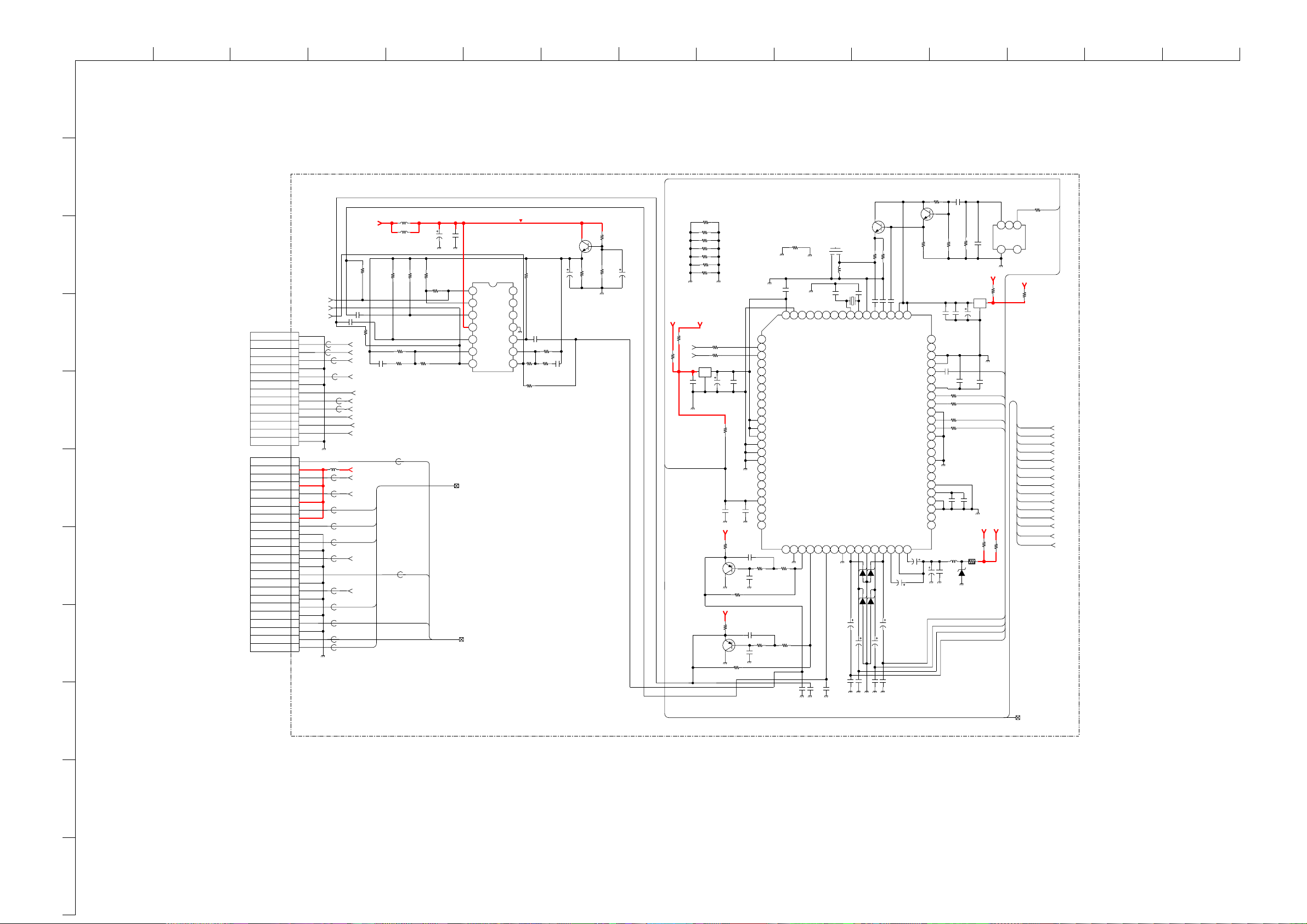
ABCDE F
G
HIJKLMN
O
1
CN2003
XX
PJE R
PJE G
PJE B
PJE BLK
DISABLE
AC ON/OFF
VPROT
+12V
+12V
+12V
H PULSE
+12V
VTIM
H SHIFT
VD(-)
VD(+)
HVPROT
CN2004
XX
A..-32NX200U
1
GND
2
3
4
5
GND
6
7
GND
8
9
SCL
10
SDA
11
12
13
14
GND
1
2
3
VS
4
5
HS
6
7
8
9
HD
10
GND
11
E/W
12
GND
13
14
GND
15
16
GND
17
VM
18
GND
19
ABL
20
GND
21
22
GND
23
24
WOOFER
LEFT
RIGHT
C1278
0.47
16V
FB2015
FB2017
FB2018
FB2002
L2003
FB2008
FB2009
FB2014
FB2020 XX
FB2011
FB2013
FB2012
FB2007
XX
FB2016
XX
XX
XX
FB2010
R1250
XX
C1277
0.47
R1251
XX
R_PJE
G_PJE
B_PJE
BLK_PJE
XX
SCL
SDA
XXFB2001
AV_MUTE
AV_PROT
AC_ON/OFF
XX
12V
VSYNC100
XXFB2005
HSYNC100
XXFB2006
AFC_PULSE
XX
XX
H_DRIVE
XX
XX
VTIM
VM
XX
XX
XX
XX
A
L1271
XX
DISABLE
9V
C1279
R1277
47k
XX
R1281
R1282
L1272
100uH
R1278
47k
XX
C1275
100
25V
R1279
47k
R1280
150k
47k
R1283
47k
XXFB2004
VPROT
E/W
XXFB2003
H SHIFT
ABL
VD(-)
X_RAY
AUDIO DECODER AND AMPLIFIER
1/9
VD(+)
C1276
0.01
C1273
R1274
100p
6.8k
+9V
R1288
560
CHIP
R1290
3.9k
CHIP
R1289
6.8k
CHIP
C1283
47
16V
ACT5VD
XX
R1136
R1137
SCL
SDA
C1231
2200p
B
B
IC1270
MC3403NS-E20
OUTPUT AMP
7654321
14 13 12 11 10 9 8
R1284
R1252
R1287
C1281
47k
XX
0.47
16V
47k
2SC2412K-R
C1282
R1286
47k
R1285
XX
10
50V
Q1272
C1280
XX
AUDIO RESET
HDEF
A 2/9
VDEF
A 2/9
A 4/9
5V_1
0
FL1231
EMI
R1260
R1261
C1232
C1233
16V
R1291
Q1268
R1294
Q1269
JR1245
XX
JR1232
XX
JR1233
XX
JR1234
XX
JR1235
XX
JR1236
XX
JR1237
XX
100
100
C1234
47
4700p
25V
B
R1234
22k
C1235
1
1
16V
9V
C1294
XX
XX
9V
C1291
R1293
C1293
R1297
R1292
XX
0
C1292
XX
XX
0
XX
XX
XX
JR1238
0
C1284
0.1
C1239
25V
B
80
1 2 3 4 5 6 7 8 9 10 11 12 13 14 15 16 17 18 19 20 21 22 23 24
STANDBY 0
NC
SCL
ADDRESS SELECT
SDA
12S CLOCK
12S WS
12S DATA OUT
12S DATA IN
ADR DATA OUT
ADR WS
ADR CLOCK OUT
8VSUP
8VSUP
8VSUP
B GND
B GND
B GND
12S DATA IN
NC
NC
NC
POWER ON RESET
NC
NC
SCB-OUT R
XX
R1296
XX
R1298
R1295
DIGITAL CONTROL OUT 1
DIGITAL CONTROL OUT 0
VREFGND2
SPEAKER OUT L
SPEAKER OUT R
SCB-OUT L
252627282930313233343536373839
XX
XX
C1236
2200p
B
C1264
C1265
2200p
B
2SC2412K-R
CF1270
6.5MHZ
C1242
4p
4p
X1231
18.43MHz
TP
NC
NC
AUDIO CLOCK OUT
IC1231
MSP3411G-QA-B10
NC
NC
SUBWOOFER OUT
NC
D1235
UDZS-12B
D1237
UDZS-12B
D1236
UDZS-12B
C1286
47
16V
C1287
47
16V
C1240
XX
2200p
B
Q1270
10uHL1270
XTAL OUT
SC2-OUT-R
C1241
XX
R1270
330
CHIP
XTAL IN
SC2-OUT-L
TEST
IF IN 2
SC1-OUT-R
VREFGND1
C1244
XX
XX
R1271
47pC1245
47p
C1270
IF COMMON IN
SC1-OUT-L
C1247
D1238
UDZS-12B
C1289
16V
C1288
47
16V
C1246
47p
C1271
IF IN 1
HP CAP
47
XX
AHVSUP
R1272
1k
656667686970717273747576777879
AVSUP
AVSUP
IFGND
IFGND
MONO IN (AM)
REF VOLTAGE
SC1-IN-R
SC1-IN-L
ASGND1
SC2-IN-R
SC2-IN-L
ASGND2
SC3-IN-R
SC3-IN-L
ASGND4
FR-IN-R
FR-IN-L
REF VOLTAGE
A GND
A GND
SP CAP
40
C1249
50V
10
2SC2412K-R
C1255
NC
NC
NC
NC
NC
414243444546474849505152535455565758596061626364
NC
10
50V
C1250
47
25V
Q1271
R1273
6.8k
0.1
C1256
0.47
R1239
C1251
R1275
C1257
0.1
R1241
R1256
4.7k
C1285
4.7
16V
L1233
10uH
39p
MTZJ-T-77
8.2C
1k
C1252
C1290
4.7k
4.7kR1240
4.7k
D1239
25V
47
4.7
FPRD
FL1232
C1254
R1299
XX
R1237
47
1/4W
C1274
R1134
EMI
0.1
39p
ACT5VD
XX
C1258
0.1
MAIN-R
MAIN-L
DTV-R
DTV-L
ACT9V
ATV-L
ATV-R
AM
R1238
0
TV-L
TV-R
123
FL1270
46
9V
R1276
5V_1
R1135
0
CHIP
RGB_TXT
A 2/9
1k
QSS
R_TXT
G_TXT
B_TXT
BLK_TXT
AUDIO.RESET
MAIN_L
MAIN_R
ATV- L
ATV- R
TV-L
TV-R
DTV-L
DTV-R
QSS
AM
2
3
4
5
AUDIO MUTE
AUDIO PROT
6
7
8
9
COMPONENTS MARKED AS XX ARE NOT FITTED ON THIS MODEL
10
11
~ A Board Schematic Diagram [ Audio Decoder and Amplifier ] Page 1/9 ~
- 39 -
Page 40

ABCDE F
G
HIJKLMN
O
1
A..-32NX200U
C1505
R_MB
IC1502
XX
IC1501
XX
R1523
XX
16 15 14 13 12 11 10 9
5V
R1521
0
R_TXT
G_TXT
R1520
G_PJE
0
G_MB
G_MB
XX
C1506
14 13 12 11 10 9
XX
5V
BLK_TXT
R1519
0
CHIP
8
BACKEND
A
2/9
R_PJE
R_MB
B_PJE
2
RGB_TXT
A 1/9
B_TXT
B_MB
R1522
0
87654321
5V
R1488
1k
100
R1443
3.3M
0
R1441
1213141516171819
YF_OFF
CXA2150AQ-TL
L2_FIL
HP_IN
Q1407
0.47
C1430
11
PABL_FIL
DPDT_OFF
IC1402
H_DRV
GND_H
R1446
XX
C1441
4700p
R1447
3.3k
16V0.1C1431
10
R1_IN
Q1405
XX
16V
B
0.1
C1432
9
VS_IN
43
R1513
XX
16V
BC1434
0.1
G1_IN
HC_PARA
44
R1448
100
R1451
100
C1433
R1400
5V
XX
SCP
DPIC
B1_IN
GND_V
XX
100
R1450
78
YSYM1
MP_PARA
45
16V0.1
B
C1436
R2_IN
DF_PARA
46
0
R1452
16V
B
0.1
C1437
GS_IN
EW_DRV
47
0
R1453
C1439
100V
MPS
9V
R1931
R1998
48
0.1
0
XX
Q1900
C1438
0.1
16V
B2_IN
V_OSC
49 50 51
C1440
XX
B
GND_SIG
V_AGC
0.1
25V
B
R1999
R1454
YSYM2
VSAW0
XX
100
0
R1468
9V
123456
VCC_OUT
PRE_RGB
SABL_IN
ABL_FIL
ABL_IN
V_DRV+
VSAW1
R_OUT
G_OUT
B_OUT
IK_IN
VCC9
VTIM
V_DRV-
R1465
R1467
L1403
C1450
XX
R1457
XX
R1455
XX
10uH
C1444
25V
R1458
64
63
62
61
60
59
58
57
56
55
54
53
52
XX
100
47
XX
R1473
100
R1463
R1460
100
R1459
R1461
R1462
C1447
0.22
25V
100
R1502
XX
100
100
100
R1466
C1460
C1449
C1446
R1442
XX
4.7
50V
XX
C1448
10k
R1500
R1504
R1471
1k
XX
XX
C1445
XX
R1503
XX
XX
C1443
0.1
0
Q1474
XX
R1449
C1411
R1485
XX
XX
VM
Q1406
2SA1037AK-R
9V
R1433
XX
C1458
0.47
16V
C1459
4.7
50V
R1476
XX
C1454
XX
L1404
10uH
9V
C1451
XX
C1473
C1472
XX
L1406
10uH
C1462
47
25V
C1461
2200p
50V
C1452
0.22
25V
9VBACKEND
VTIM
Q1422
2SA1037AK-R
Q1423
2SC2412K-R
C1455
47
0.22
25V
25V
C1471
R1484
XX
C1470
XX
R1482
XX
XX
R1483
R1486
1/10W
XX
100
6.8K
C1457
100
25V
C1501
XX
C1464
0.22
25V
Q1410
2SA1037AK-R
R1487
1k
L1405
10uH
R1464
4.7k
R1472
R1456
2.2k
9VDEFLECTION
R1480
R1481
XX
Q1420
XX
C1476
2k
XX
Q1421
XX
R1517
XX
R1518
XX
R1498
R1491
9V
100
16V
R1490
1k
R1489
R1475
R1478
R1514
XX
R1494
1k
Q1411
2SA1037AK-R
R1493
100k
10k
XX
R1495
56k
10k
CHIP
DAN202K-T-146
R1499
560
CHIP
R1479
XX
DF_PARA
XX
PRE-RGB
A 3/9
Q1501
XX
R1496
R1508
1K
1/10W
D1406
UDZS-9.1B
D1403
C1475
0.1
16V
0
R1477
XX
C1502
XX
1k
2SA1037AK-R
R1492
5.6K
1/10W
R1509
1/10W
9V
6V
1K
Q1412
R1515
R1497
1k
R1827
XX
XX
R1828
0
CHIP
C1503
XX
Q1502
XX
R1510
1K
1/10W
Q1413
2SA1037AK-R
R1811
2.2k
CHIP
R1516
XX
D1804
DAN202K-T-146
D1805
MA3051M-TX
DTC144EKA
C1504
Q1503
Q1802
XX
XX
R1815
D1806
DAN202K-T-146
10k
C1981
2SC2412K-R
0.1
16V
A 3/9
Q1804
BLK_MB
VM
47
R1841
47
R1842
47
R1843
FB1801
FB1802
FB1803
DF_PARA
A 4/9
VSAW
A 4/9
0
0
0
BLK_PJE
IK
A 3/9
654321
7
R,G,B OUT
A 3/9
L1401
3
4
5
C1479
XX
C1478
XX
6
R1505
0
R1506
7
8
9
10uH
C1402
100
25V
R1402
R1403
R1401
XX
D1401
XX
C1477
XX
0
Y100
U100
9VBACKEND
R1507
V100
0
HSYNC100
XX
XX
C1401
XX
C1404
0.22
25V
C1403
0.22
25V
R1405
XX
Q1401
5V
C1405
C1407
0.22
XX
R1404
XX
SDA
SCL
SCP
C1406
R1406
CHIP
1000p
50V
10k
R1407
XX
R1408
R1427
R1409
XX
25V100
2SC2412K-R
C1409
0.33
B
XX
0
Q1402
R1410
XX
H_DRIVE
A 4/9
IC1401
XX
4321
C1415
XX
R1415
XX
L1402
10uH
C1416
100
25V
0.1
C1412
0.1
C1413
0.1
C1414
100
R1411
R1417
100
100
R1412
100
R1413
C1420
0.33
R1414
10k
4700pC1410
R1416
C1408
15k
0.47
C1715
1000p
50V
8765
C1418
0.22
25V
R1419
XX
C1417
XX
9VBACKEND
20
21
22
23
24
25
26
27
28
29
30
31
32
X1401
2.696MHz
R1423
XX
R1424
XX
C1425
100p
XX
R1425
R1420
XX
R1421
XX
R1428
4.7k
Y_IN
CB_IN
CR_IN
F0
F1
SDA
SCL
SCP
HS_IN
VREG5
VBIAS
IREF_HV
AFC_FIL
R1422
9VDEFLECTION
VSYNC100
R1435
2.2k
R1439
XX
R1431
XX
Q1404
XX
C1423
XX
XXR1429
R1426
XX
C1426
0.22
R1430
C1424
XX
50V4.7
100
R1437
BPH
VCC5
CLP_C
IREF YC
VM_MOD
TP 7
TP 8
TP 9
CERA
33
470
VCOMP_IN
VPROT
HCOMP_IN
HPROT
34 35 363738 394041 42
XX
R1432
C1421
XX
R1438
XX
C1422
R1445
XX
XX
R1434
2.2k
C1419
0.1
50V
R1501
4.7K
2.7k
R1440
XX
B
R1418
XX
R1436
R1444
VM_OUT
2SA1037AK-R
10
11
HDEF
A 1/9
VDEF
A 1/9
A 4/9
- 40 -
MP_PARA
A 4/9
HC_PARA
A 4/9
COMPONENTS MARKED AS XX ARE NOT FITTED ON THIS MODEL
~ A Board Schematic Diagram [ Backend ] Page 2/9 ~
Page 41

ABCDE F
G
HIJKLMN
O
1
2
A..-32NX200U
COMPONENTS MARKED AS XX ARE NOT FITTED ON THIS MODEL
R1131
10k
5V
R1807
3
4
R1801
5
47k
15V_PULSE
C1802
C1803
0.22
R1802
2.2k
C1801
100p
R1805
100k
D1801
DAN202K
D1802
DAN202K
R1803
100k
R1804
C1804
0.047
25V47
D1803
DAN202K
10k
2SC2412K-R
Q1801
6
PRE-RGB
A 2/9
10k
R1806
470
C1805
4321
3300p
B
C1807
25V
C1806
0.047
25V
IC1801
LM393DT
C1808
0.1
8765
R1814
6.8k
CHIP
R1809
10k
CHIP
0.1
25V
B
R1810
XX
R1826
100k
R1831
56k
R1812
15k
2SC2412K-R
R1829
1k
CHIP
R1813
15k
Q1803
R1830
0
C1812
D1808
DAN202K
D1807
DAN202K-T-146
XX
12V
R1835
220
Q1805
2SB734-4
R1930
2.2k
R1839
15k
R1845
XX
D1810
1SS133
D1809
ERA82-004
R1838
R1844
R1840
1k
R1850
3.3k
10k
XX
R1851
XX
R1849
C1814
25V
4321
XX
47
LM393DT
R1852
3WRS15
IC1804
R1855
RN-CP
R1854
470k
R1861
4.7k
3.3k
RN-CP
C1818
XX
C1819
XX
R1856
220k
CHIP
L1801
10mH
8765
C1822
0.47
8765
IC1805
XX
4321
C1821
R1866
XX
9V
D1811
DAN202K-T-146
XX
R1870
2.2K
1/10W
D1NL20U-TR
D1813
C1833
0.0047UF
630V
R1876
7
12k
C1832
0.22
S
IRF720-LF49
R1879
RN-CP
Q1809
8.2k
R1886
22k
C1837
0.01
50V
R1882
2.2k
4321
IC1808
LM393DT
5
6
7
R1890
2.2k
CHIP
C1843
0.015
630V
PP
R,G,B OUT
R1898
10k
1/10W
8
A 2/9
9V
C1800
4700p
50V
R1905
150k
RN-CP
R1906
1k
RN-CP
12V
IC1811
LA6500-FA
12345
C1850
47
25V
R1909
4.7k
RN-CP
R1911
220k
R1916
2.2
1W
RS
L1802
10mH
C1852
0.47
50V
L1803
10uH
C1855
47
25V
C1853
0.22
25V
12V
C1854
47
25V
C1859
100
25V
9V
C1856
0.22
25V
F
-15v
IC1812
BA12T
OUT
-15v
15V_PULSE
15v
-15v
VCC
TP16
GND
C1861
470
25V
TP15
VM
A 2/9
9V
TP10
TP11
TP12
CN1802
8P
WHT
8
15V_PULSE
7
GND
6
+15V
5
GND
4
-15v
3
V-
V-
2
GND
1
V+
V+
CN1803
5P
WHT
1
VM
2
GND
3
+9V
4
QP-
5
GND
CN1804
8P
WHT
1
R_OUT
2
GND
3
G_OUT
4
GND
5
B_OUT
6
GND
7
+12v
8
IK
TO D1 BOARD
CN8612
TO VM BOARD
CN5602
TO C1 BOARD
CN9001
10
11
8
IK
ROTA
A 2/9
A 4/9
A
3/9
DEFLECTION
DEF
A 4/9
9
~ A Board Schematic Diagram [ Deflection ] Page 3/9 ~
- 41 -
Page 42

10
1
2
3
4
5
6
7
8
9
ABCDE F
A..-32NX200U
A
4/9
DEFLECTION, PICTURE ROTATION
9VDEFLECTION
TP13
IC1701
STV9379
1234567
C1701
XX
C1703
330
25V
D1701
MTZJ-T-77-18B
C1704
100
R1701
6.2K
1/10W
R1703
3.9k
1/10W
D1702
GP08DPKG23
R1702
1/10W
50V
C1702
XX
C1705
0.01
50V
C1706
0.22
100V
MPS
R1705
1.5
1/4W
R1704
3.9k
6.2k
1/10W 1/10W
JW1702
5
C1707
470p
500V
B
C1709
0.001
400V
MTZJ-T-77-15B
D1703
C1708
0.1
100V
MPS
R1706
4.7
1/4W
R1707
22
1/4W
TH1701
TP14
C1711
Q1701
IRF620
0.01
50V
S
R1709
R1708
220
3W
1.8
1/2W
R1710
3.3k
CHIP
C1710
100V
0.47
MPS
R1711
C1712
1/2W
R1933
D1704
MMDL914T1
R1715
XX
R1714
7.5k
V-
22k
C1953
0.1
16V
15v
MMDL914T1
C1720
10
50V
H_DRIVE
A 2/9
100
50V
L1701
8.2uH
1.8
RN
V+
R1934
R1937
D1705
CHIP
Q1973
2SC2412K-R
1k
XX
-15v
R1935
R1936
4.7k
10k
C1721
CN1711
HD
VDEF
A 1/9
A 2/9
R1469
100
R1470
100
HC_PARA
A 2/9
9V
R1721
82k
1/10W
R1723
18k
1/10W
0.01
25V
MP_PARA
A 2/9
R1722
10k
1/10W
XX
1
GND
DF_PARA
9V
C1970
Q1971
2SC2412K-R
R1972
4.7k
CHIP
R1970
XX
Q1970
2SC2412K-R
9V
R1971
2.2k
R1996
XX
R1997
XX
10
50V
R1973
CHIP
R1974
G
DF_PARA
A 2/9
+9V
R1976
120K
21
IC1802
LM358DR
Q1972
XX
2.2k
R1977
XX
C1971
10
50V
R1975
10k
3
4
33k
R1978
10k
R1979
10k
CHIP
C1972
0.01
25V
R1995
68k
9V
Q1974
XX
8765
R1932
C1973
XX
0.01
25V
B
9V
R1981
XX
C1975
10
50V
R1968
R1980
47k
XX
1/10W
C1974
10
50V
C1980
R1969
15k
0.1
25V
R1984
R1966
R1983
220k
CHIP
10k
CHIP
R1985
47k
CHIP
XX
D1901
0
R1982
R1990
R1986
47k
1/10W
R1987
10k
R1988
1/10W
R1989
CHIP
CHIP
47K
10k
9V
22k
33
R1967
150k
1/10W
HIJKLMN
ROTA
A 3/9
DEF
R1991
XX
R1992
XX
C1977
XX
R1993
C1976
XX
A 3/9
R1862
R1857
XX
R1858
XX
R1859
XX
R1860
XX
R1846
XX
R1853
Q1806
R1950
51k
RN-CP
R1951
1.8k
RN-CP
XX
XX
R1952
6.8k
CHIP
R1953
470
1W
RS
R1817
100
CHIP
100R1819
R1820
100
100
R1821
100
R1816
100
R1823
XXR1824
100
R1825
C1813
XX
R1834
XX
VSAW
A 2/9
XX
XX
Q1807
XX
R1863
XX
R1864
XX
C1820
XX
Q1808
XX
R1865
XX
+9V
ROTATION (N/S)
12345
C1950
0.1
16V
R1954
15
1/4W
FPRD
MB88141APF-ER
XXR1818
7654321
8 9 10 11 12
C1823
XX
XX
R1867
C1824
XX
5V
IC1950
LA6500-FA
IC1803
R1868
SCL
SDA
R1869
XX
C1826
C1825
XX
XX
XX
R1955
24 23 22 21 20 19 18
17 16 15 14 13
560
CHIP
R1872
R1871
XX
C1828
XX
C1829
XX
C1827
0.33
25V
C1951
0.1
50V
MPS
XX
C1830
XX
-15V
C1816
0.1
25V
R1847
100
CHIP
R1848
100
CHIP
R1874
C1831
R1902
R1891
R1892
C1841
R1893
R1888
XX
R1894
XX
R1897
XX
XX
XX
C1842
XX
-15v
XX
R1918
R1903
XX
-15v
XX
R1904
XX
XX
R1899
XX
Q1811
2SA1037AK
C1847
XX
4321
IC1809
XX
R1912
XX
R1908
2.2k
CHIP
R1910
C1848
XX
XX
XX
D1816
XX
R1914
XX
JW1801
8765
R1919
C1851
XX
R1917
XX
R1915
XX
C1838
181716151413121110
IC1806
XX
XX
+12V
XX
R1880
9V
R1956
1.5
1/4W
FPRD
SDA
SCL
5V
C1817
10
50V
XX
R1883
XX
987654321
D1814
XX
C1840
XX
XX
R1957
1
1/4W
C1952
47
25V
12V
R1924
XX
5
XX
R1922
XX
C1858
XX
12V
AC_RY_LATCH
Q1812
Q1813
R1925
R1929
XX
15v
R1199
R1198
XX
XX
XX
HD
R1133
100
0
XX
D1407
0
R1132
100
R1928
XX
9V
0R1900
1
DF_PARA
2
MP_PARA
3
E/W
4
HC_PARA
5
H_DRIVE
6
AFC_PULSE
7
ABL
8
X_RAY
9
GND
10
ZOOM_COMP
CN1901
1
ROT-
2
NC
3
ROT+
CN1902
1
CY+
2
NC
3
CY-
1
PRE_RGB
2
DF_DRIVE
3
H_CENTRE
4
NC
5
+9V
6
GND
7
GND
1
+15V
3
+12V
4
H_PROT
5
HOP_OVP
6
AFC_PULSE
7
DF_DRIVE
8
ABL
9
GND
10
GND
11
GND
CN1805
10P
YEL
3P
WHT
XX
CN1807
7P
WHT
CN1903
10P
O
TO D BOARD
CN8500
TO ROT COIL
TO CY
TO D1 BOARD
CN8616
TO D2 BOARD
CN6801
COMPONENTS MARKED AS XX ARE NOT FITTED ON THIS MODEL
11
~ A Board Schematic Diagram [ Deflection, Picture Rotation ] Page 4/9 ~
- 42 -
Page 43

1
2
3
4
5
6
7
8
9
10
ABCDE F
A..-32NX200U
A
5/9
V_PULSE
H_PULSE
MAIN_Y
MAIN_U
MAIN_V
CV_TEXT
D.CVBS
AV_LINK
AV_LINK,CV_TEXT
SDA_1
SCL_1
R1103
XX
AV_LINK,CV_TEXT
AV_LINK,CV_TEXT
INTERFACE
R1114
XX
R1112
XX
R1099
XX
R1121
0
CHIP
SDA1
5V_JACT
R1122
SCL1
R1113
XX
JR1005
XX
JR1004
XX
CHIP
0
SDA
SCL
5V_1
9V
ACT9V
33V
HP_MUTE
DTV-R
DTV-L
TV-R
TV-L
ATV-R
ATV-L
MAIN_R
MAIN_L
QSS
AM
JR1003
XX
TP6
AV4_C
AV4_Y
R1126
R1123
R1124
R1130
HP_R
HP_L
AV4_R
AV4_L
JR1006
CHIP
0
COMB-C
COMB-Y
0
XX
R1125
XX
XX
R1128
JR1007
CHIP
D1016
UDZS-5.6B
D1017
D1NL20U-TR
1
GND
2
GND
3
FBLK
4
GND
5
V PULSE IN
6
H PULSE IN
7
Y MAIN IN
8
GND
9
U MAIN IN
10
V MAIN IN
11
CVBS TXT
12
GND
13
SUB-C
14
SUB-Y
15
GND
16
D-CVBS OUT
17
AV4-C OUT
18
ATV-CV OUT
19
AV4-Y OUT
20
GND
21
AV LINK
22
GND
23
SDA
0
24
SCL
25
R1104
0
CHIP
26
27
28
29
30
31
32
33
34
35
36
37
38
39
40
41
42
43
44
45
46
47
48
49
50
SDA1
SCL1
+5V
+9V
+33V
GND
HP-MUTE
GND
HP-A IN
HP-L IN
AV4-R OUT
AV4-L OUT
GND
GND
DTV-R OUT
DTV-L OUT
TV-R OUT
TV-L OUT
ATV-R OUT
ATV-L OUT
MAIN-R IN
MAIN-L IN
GND
AGC MON
QSS
AM
CN1001
50P
0R1129
XXR1054
XXR1127
0
HSYNC100
Y100
U100
V100
DPIC
R1108
0
R1109
0
TO J2 BOARD
CN1001
0
C1047
2200
10V
VSYNC100
DPIC
R1107
XX
1.8V
+5V_STBY
C1049
R1090
XX
R1091
XX
D1015
D1NL20U-TR
0.1
B
R1118
XX
3.3V
A5V
5V
6V
Y
B-Y
R-Y
R1088
XX
R1092
XX
R1089
MAIN_Y
MAIN_U
FB1011
R1116
XX
0
IC1012
BA033T
VCC
0
R1248
R1245
GND
0
R1247
R1246
OUT
TP5
FB1012
XX
0
XX
R1110
XX
MAIN_V
V_PULSE
H_PULSE
TP1
R1105
R1117
D1012
UDZSTE-174.7B
C1052
470
6.3V
TP4
TP2
TP3
XX
SCL
SDA
0
2.5V
0
R1106XX
R1111
XX
MAIN_Y
FL1010
EMI
1
MS_SHUT_DOWN
2
GND
3
GND
4
GND
5
GND
6
GND
7
GND
8
GND
9
GND
10
GND
11
VP 100 IN
12
HP 100 IN
13
GND
14
Y100 IN
15
GND
16
U100 IN
17
GND
18
V100 IN
19
GND
20
D.PIC
21
GND
22
RESET 100
23
SCL
24
SDA
25
+2.5V
26
+5v
27
5VA / 3.3V
28
+3.3V DIGITAL
29
GND
30
HP SUB /5VD
31
VPSUBOUT/Y_SUB
32
+1.8V
33
GND
34
VSUBOUT/C_SUB
35
GND
36
USUB OUT/INT_COL
37
GND
38
YSUBOUT/FB
39
GND
40
GND
41
GND
42
YMAINOUT/B
43
GND
44
UMAINOUT/G
45
GND
46
VMAINOUT/R
47
GND
48
VPLSE_M/Y_M
49
GND
50
HPLSE_M/C_M
CN7109
50P
3.3V_STBY
C1053
10
50V
G
TO B5 BOARD
CN4472
R1032
XX
SCL
2SK2036-TE85L
SDA
HIJKLMN
COMPONENTS MARKED AS XX ARE NOT FITTED ON THIS MODEL
Q1009
2SK2036-TE85L
Q1010
S
S
+5V_STBY
QSS
QSS
VIDEO
A 7/9
AM, QSS
A 7/9
R1138
R1139
XX
+5V_STBY
XX
R1031
AM
AM
AGC MON
A 7/9
10K
R1087
0
CHIP
AC_ON/OFF
3.3V_STBY
MAIN_L
MAIN_L
DISABLE
+5V_STBY
9V
SDA-TV
R1086
0
R1160
XX
+5V_STBY
MAIN_R
MAIN_R
SCL-TV
SCL1
SDA1
ATV-L
ATV-R
ATV-R
ATV-L
R1147
4.7K
1/10W
R1148
4.7K
1/10W
AUDIO.RESET
BLK_MB
B_MB
G_MB
R_MB
SCL1
SDA1
VSYNC100
HSYNC100
TV-L
TV-L
PROT
R1055
10k
DGCRY
PWR
N-RESET
AV_PROT
OCP
AV_PROT
HM[1]
HM[2]
HM[3]
HM[4]
CV_TEXT
MAIN-RY
PROT
TV-R
TV-R
AGC-DEF
Attn
SCL
SDA
D1008
DAP202K
DISABLE
FB1016
0uH
EMM_ISO
FB1005
0uH
FB1020
0uH
AV_MUTE
R1041
10k
FB1008
FB1010
R1119
FB1017
0uH
FB1006
0uH
FB1018
0uH
0uHFB1019
R1063
R1080
DTV-L
DTV-L
R1039
100
CHIP
R1040
100
CHIP
FB10090uH
0R1120
FB1014
0uH
0
FB1015
0uH
R1094
FB1007
R1056
R1084
R1085
5V
0
XX
DTV-R
LEFT
LEFT
DTV-R
5V
100
R1044
R1045
R1046
R1102 XX
R1042
100
CHIP
D1009
UDZTE-5.6B
0uHFB1203
0uH
0uH
100
0uH
XX
XX
XX
FB1204
0uH
LEFT
2.5V
D1007
DAP202K
R1043
100
100
100
0R1047
R1093
RIGHT
RIGHT
RIGHT
AOPP
A 6/9
A 7/9
87654321
0
D1010
DAN202K
1
Disable
2
GND
3
GND
4
KEY2
5
MS_SHUT_DOWN
6
KEY1
7
INT_COL
8
RESP.LED
9
AV LINK
10
SIRCS
11
SCL0
12
GND
13
SDA0
14
GND
15
RESET AUDIO
16
GND
17
VIDEO
18
GND
19
RESET100
20
RSTIN
21
TXTBLK
22
TC LED
23
TXTB
24
ST.BY
25
TXTG
26
PROT
27
TXTR
28
ACON/OFF
29
SCL_DIG
30
GND
31
SDA_DIG
32
GND
33
VP100
34
+5V
35
HP100
36
+5V
37
GND
+5V/+3.3V STBY
38
39
AUDIO MUTE
40
NC
CN1000
AV_MUTE
WOOFER
WOOFER
CXA1875AM-T4
I/O EXPANDER
OV PROT
2.5V PROT
PORT 2
DGCRY
PWR
40P
AUDIO.RESET
IC1008
ATTN
N-RESET
GND
R1048
D1011
UDZTE-5.6B
AUDIO.RESET
Y
Y100
0
TO M2 BOARD
Y100
B-Y
U100
16 15 14 13 12 11 10 9
+5V
SCL
SDA
SA2
SA1
SA0
OC PROT
AUDIO PROT
1
GND
2
SCL
3
SDA
4
DISABLE
5
NC
CN100
U100
CN1999
5P
RED
V100
R-Y
V100
+5V_STBY
+5V_STBY
3.3V_STBY
+5V_STBY
GND (HP)
AV4 LEFT IN
CN7108
HSYNC100
HSYNC100
R1049
SERVICE
CN7107
XX
GND
GND
GND
XX
VSYNC100
VSYNC100
100
R1050
100
HM[1]
HM[2]
UDZS-6.2B
HM[1]
HM[2]
HM[4]
HM[3]
HM[3]
HM[4]
D1014
1
2
3
1
2
3
4
5
6
7
R_MB
R_MB
SCL-TV
UDZS-6.2B
G_MB
D1013
R1082
CHIP
R1083
G_MB
0
XX
HP_R
AV4_C
AV4_Y
AV4_L
AV4_R
SDA-TV
HP_L
B_MB
B_MB
BLK_MB
BLK_MB
CN1701
11P
WHT
HEADPHONE R OUT
1
2
GND (HP)
HEADPHONE L OUT
3
4
GND (HP)
5
AV4 CHROMA IN
6
GND
AV3 LUMINANCE IN
7
8
GND
9
AV4 LEFT IN
10
GND
11
AV4 RIGHT IN
TO H3 BOARD
CN907
CN1703
XX
1
KEY2/SCL 3.3
2
GND (KEY)
3
KEY1/SDA 3.3
CN1706
8P
WHT
1
KEY2/SCL 3.3
GND(KEY)
2
3
KEY1/SDA 3.3
4
STDYBY +5V/3.3V
SIRCS/AV_INT
5
6
RESP LED/RESET
AVLINK
7
STDBY 5V
8
CN1702
4P
1
GND
2
STBY +5V
3
SIRCS
4
LED
O
TO FRONT CONTROL
TO H BOARD
CN302
TO H BOARD CN301
AND
F3 BOARD CN2151
11
~ A Board Schematic Diagram [ Interface ] Page 5/9 ~
- 43 -
Page 44

ABCDE F
G
HIJKLMN
O
1
A..-32NX200U
TO G BOARD
CN6006
+11V
GND
+6V
GND
AU (+)
AU (+)
AU (-)
123456789
AU (-)
GND
+33V
STBY +5V
101112
OCP
13
OVP
CN2000
13P
WHT
MAIN RY
DGC RY
GND
12345
STBY +6V
AC DET
CN1602
5P
WHT
2
+5V_STBY
R1068
R1069
4.7k
3.3V_STBY
R1077
XX
0
R1076
1k
IC1102
PQ070XZ01ZP
3.3V
C1054
10
50V
4.7k
AC_ON/OFF
MAIN-RY
4.7k
Q1072
DTC144EKA
VIN
12345
C1055
0.1
25V
VC
C1056
0.1
25V
VO
VADJ
GND
R1052
R1051
1k
390
RN-CP
RN-CP
1.8V
C1057
100
16V
11V
6V
3
ACT7V
C1050
0.1
25V
IC1013
BA05T
VCC
OUT
GND
C1051
100UF
25V
4
CN1603
5
TO G1 BOARD
CN4603
8P
1
+33V
2
+23V
3
GND
4
GND
5
+12V
6
+9V
7
GND
8
GND
ACT33V
ACT23V
ACT12V
ACT9V
6
CN1604
10P
1
+7V
2
+7V
3
GND
4
7
TO G1 BOARD
CN4602
GND
GND
GND
GND
+5V
+5V
ACTIVE PWR
5
6
7
8
9
10
ACT7V
R1062
XX
6V
12345
FB1001
0.45UH
C1002
470UF
10V
C1004
XX
R1061
0
12345
FB1002
0.45UH
C1003
470UF
10V
C1005
XX
PQ1CG2032FZ
PQ1CG2032FZ
IC1002
L1011
15UH
D1001
D5S4M
0.068UF
IC1003
C1059
C1006
50V
L1000
15UH
D1002
D5S4M
ACT5V
L1013
10UH
C1060
100UF
0.1
25V
25V
R1005
1.1K
R1003
R1001
1K
4.7K
L1012
15UH
C1010
1000UF
6.3V
R1004
R1006
470
1.5K
L1006
R1053
15UH
390
R1002
C1011
1000UF
4.7K
6.3V
C1007
0.068UF
50V
L1001
10UH
C1061
0.1UF
25V
L1002
10UH
5V_JACT
ACT2.5V
C1012
470UF
6.3V
ACT3.3V
C1013
470UF
6.3V
AOPP
A 5/9
A 7/9
PS1011
AU+
6V
IC1005
BA05T
VCC
0.1
25V
B
C1024
D1210
D1NS4
C1025
GND
6V
FB1003
5MM
470
10V
FB1004
5MM
470
10V
D1211
D1NS4
C1023
6V
33V
PS1012
AU-
OUT
C1028
100
25V
IC1006
PQ1CG2032FZ
12345
L1007
15uH
C1026
D1005
D5S4M
XX
IC1007
PQ1CG2032FZ
12345
C1027
XX
D1006
D5S4M
OCP
L1020
R1033
CHIP
C1029
L1008
15uH
R1034
4.7k
CHIP
C1030
0.068
MPS
XX
4.7k
0.068
MPS
OVP
C1031
0.1
25V
R1036
1k
R1035
910
A5V
B
R1037
RN-CP
L1010
C1032
1000
L1009
15uH
C1033
+5V_STBY
AC_RY_LATCH
1.1k
L1004
15uH
6.3V
R1038
1.5k
RN-CP
1000
6.3V
10uH
L1005
10uH
C1043
2.5V
3.3V
0.1
25V
C1034
470
6.3V
C1035
470
10V
C1045
100
25V
R1070
10k
C1037
11V
0.01F
16V
OUT
IC1011
BA05T
VCC
GND
C1044
0.1
25V
2SA1037AK-QR
2SC2412K-T-146-QR
R1071
10k
C1036
0.1
25V
B
11V
FB1013
5MM
C1039
C1046
2200
25V
Q1071
Q1070
C1070
1
50V
IC1009
L7809CV
O
I
IO
G
G
IC1010
PQ1CG2032FZ
12345
XX
D1018
D5S4M
C1014
0.22
50V
R1058
DGCRY
R1072
1k
R1073
10k
HOP PROTECTION
C1038
C1040
100
25V
R1146
2.7k
R1145
RN-CP
910
L1018
L1017
15uH
15uH
R1144
C1042
4.7k
1000
CHIP
6.3V
C1041
0.068
MPS
R1057
15k
R1074
0.1
25V
6.8k
CHIP
9V
B
0
L1019
10uH
R1059
4.7k
D1019
XX
Q1011
2SC2412K-R
5V
C1062
470
6.3V
R1060
1k
+5V_STBY
R1078
R1075
D1070
DAP202K-T-146
Q1012
2SC2412K-R
10
11
8
9
REGULATORS
A
6/9
COMPONENTS MARKED AS XX ARE NOT FITTED ON THIS MODEL
~ A Board Schematic Diagram [ Regulators ] Page 6/9 ~
- 44 -
Page 45

ABCDE F
A..-32NX200U
G
HIJKLMN
O
1
OVP
R1021
47k
CHIP
D1004
DAN202K
R1066
C1018
0.01
B
R1067
XX
+5V_STBY
C1019
0.1
25V
R1016
100
CHIP
XX
C1020
R1027
2SC2412K
100
16V
C1022
100p
CH
4.7k
CHIP
Q1007
R1017
R1022
12k
R1023
6.8k
CHIP
XX
PROT
R1065
47K
C1058
100UF
16V
L1003
10uH
Q1004
2SC2412K
C1021
XX
R1024
R1152
R1018
470
R1019
470
100
0
R1064
39K
R1025
470
R1026
470
CHIP
L1101
C1104
100
16V
R1020
470
5V_1
XX
C1105
2SA1037AK
VIDEO
A 5/9
9V
R1028
10
Q1006
2SC2412K
R1029
470
CHIP
0.01
25V
Q1005
CN1003
XX
GND
1
CN1004
2SA1037AK
R1030
560
CHIP
GND
1
1P
Q1008
D1003
R1079
S
XX
TUNER
Q1101
R1151
XX
OCP
XX
R1143
DAN202K
SDA_1
SCL_1
XX
IC1201
TDA7482
POWER-OFF-MUTE
D1201
DAN202K
R1205
100
C1202
FB1201
1.1uH
R1201
470
CHIP
47
25V
AUDIO EARTH
1
2SA1037AK
R1204
2.7k
1/4W
C1201
0.22
25V
CN1251
CHIP
Q1201
R1208
2.2k
CHIP
L1201
65uH
C1203
0.68
MPS
WOOFER
D1202
DAP202K
2
11V
WOOFER_SP
3
WOOFER
HP_MUTE
4
5
RIGHT_SP
LEFT_SP
6
R1202
1/4W
R1236
XX
LEFT
7
RIGHT
ACT7V
8
2.7k
R1235
AUDIO L
AUDIO R
C1001
0.1UF
R1203
2.7k
1/4W
XX
R1207
C1204
25V
IC1001
BA05T
VCC
4.7
1W
0.1
GND
R1206
XX
OUT
C1205
2200
25V
R1210
47k
CHIP
Q1202
2SC2412K
FB1202
1.1uH
D1204
DAN202K
D1203
DAP202K
R1209
2.2k
CHIP
MAIN-RY
LM1786TF
AUDIO AMPLIFIER
LEFT AND RIGHT
R1213
4.7
1W
C1206
0.1
25V
R1211
3.9k
CHIP
R1212
3.9k
C1008
100UF
25V
R1214
C1209
IC1202
R1216
CHIP
R1217
C1210
50V
C1207
0.1
C1208
0.1
C1009
0.1UF
25V
CHIP
560p
22k
680
22
SL
AUDIO AMPLIFIER WOOFER
OUTPUT
BOOTDIODE
BOOT
N.C.
C1211
0.1
B
R1215
150
RN-CP
AV_MUTE
OUT S
+VCC POWER
C1213
50V
C1215
2200p
B
R1220
10k
D1205
DAN202K
1
2
3
OUT C
-VCC POWER
R1218
CHIP
R1219
680
22
ACT5VD
FEED CAP.
CN1203
XX
WOOFER
NC
GND
GND C
22k
C1214
0.1
C1717
0.1UF
25V
187654321514131211109
0
187654321514131211109
C1212
0.1
L1804
10UH
C1716
100UF
25V
FREQ.
SIGNAL GND
C1216
100p
CH
C1217
0.01
B
MUTE
IN C-
-VCC SIGNAL
INPUT
C1219
R1221
0
CHIP
IN C+
STBY
R1222
47k
CHIP
STBY/MUTE
+VCC POWER
0.1
C1220
0.1
C1218
2.2
16V
2SC2412K
R1223
47k
CHIP
GND R
MUTE
R1224
47k
CHIP
V REG.
+VCC POWER
C1221
XX
R1225
27k
CHIP
Q1203
IN S-
IN S+
-VCC POWER
-VCC POWER
C1222
0.1
63V
R1227
CHIP
R1228
STBY
+VCC POWER
R1226
XX
C1223
1000
35V
C1227
1000
35V
8.2k
XX
C1224
150
63V
C1225
0.22
L1202
2.2uH
C1228
50V
Q1204
2SC2412K
2SC2412K
AU+
C1226
0.1
25V
B
L1203
2.2uH
2.2
Q1205
AU+
AU+
C1229
3300
25V
AU-
C1230
0.1
25V
AU-
R1230
47k
CHIP
R1229
4.7k
CHIP
B
5V_1
C1238
0.22
AU-
R1232
CHIP
C1237
3300
25V
R1242
47k
CHIP
25V
B
10k
MAIN-RY
FL1011
0UH
EMI
5V_1
R1233
XX
Q1206
XX
D1207
MA73TX
D1206
UDZSTE174.7B
5V_15V
R1243
XX
R1244
CHIP
R1013
1.8k
CHIP
C1719
XX
UDZS-5.1B
DTC144EKA
Q1001
2SC2412K
C1017
D1209
Q1207
R1101
XX
330
16V
R1096
AUDIO PROTECTION
R1009
R1007
10k
CHIP
LEFT_SP
9V
L1100
XX
C1100
XX
47k
10k
CHIP
RIGHT_SP
OUT
C1103
XX
WOOFER_SP
CP1100
XX
MAIN
SUB
OUT
+BGND
3
C1101
XX
R1011
10k
CHIP
BST
R1100
XX
Q1100
IN
SW2ATT
XX
ANT
1
AGCASSCL
ATTSW
R1097
0
R1095
15k
R1008
1UH
0
AGC-DEF
C1102
XX
R1014
0
CHIP
Q1003
DTA144EKA
Q1002
2SC2412K
R1010
1UH
SCL
5V_1
Attn
SDA
SDA
BB
TU1001
BTF-EU611
TU
R1012
CHIP
33V
D1020
10K
L1015
XX
XX
L1016
XX
IF
C1722
D1021
C1063
XX
XX
XX
R1015
1k
CHIP
GND
FB1021
R1149
FB1022
+5VAMQSS
XX
XX
C1064
XX
XX
5V_1
VIDEO
R1098
R1140
XX
R1141
XX
NC
XX
S
R1142
XX
AV_PROT
R1150
XX
Q1102
XX
CN1005
XX
1
GND
AOPP
A 5/9
A 6/9
CN1007
XX
GND
1
CN1006
XX
ANALOGUE TUNER
1
GND
CN1008
XX
1
AGC MON
A 5/9
GND
10
11
CN1201
4P
LEFT_SP
9
RIGHT_SP
WOOFER_SP
1
LEFT SP
2
GND
3
RIGHT SP
4
GND
CN1202
1
WOOFER SP
2
NC
3
GND
4
NC
WHT
RED
4P
TO SUB WOOFER
A
7/9
AUDIO AND ANALOGUE TUNER
QSS
AM
AM, QSS
A 5/9
COMPONENTS MARKED AS XX ARE NOT FITTED ON THIS MODEL
~ A Board Schematic Diagram [ A udio and Analogue Tuner ] P a ge 7/9 ~
- 45 -
Page 46

ABCDE F
G
HIJKLMN
O
TO N BRD CN3501
B25
FERESET
A25
NC(GPIO)
C24
PTEN/W_TSEN
TS_ERR
A24
B24
AC3RESET
SDA(TV)
SCL(TV)
GND
GND
GND
A22
A23
B22
C22
C23
B23
3V3
3V3
A21
C21
C20
B21
GND
GND
GND
GND
GND
GND
GND
3V3
A20
C19
B20
2V5
2V5
2V5
5VD
A18
A19
C17
C18
B18
B19
AC3CLK
GND
GND
GND
5VD
B17
CLK
A16
A17
C15
C16
B16
AC3SW
CSYNC
VSYNC
GND
GND
GND
A14
A15
C14
C13
B14
B15
HSYNC
B13
AC3BOOT
VDO (7)
VDO (5)
VDO (6)
VDO (4)
VDO (3)
VDO (2)
VDO (1)
AC3INT
A11
A12
A13
C11
B12
C12
B11
VDO (0)
SPDIF
GND
GND
A10
C10
B10
A9
C8
C9
B9
R/Y (RGB)
G/C (RGB)
RGB_B
MODE
CVBS
GND
GND
GND
5VA
A8
C7
B7
B8
12VA
GND
GND
A7
C6
B6
GND
GND
A5
A6
C5
C4
B5
FBLK
GND
GND
B4
GND
GND
GND
A2
A3
A4
C2
B2
B3
C3
MUTE
C1
LEFT
B1
RIGHT
A1
CN4000
96P
1
A..-32NX200
LWB_TONE
TS1
B32
C32
NOT_LNBO VA
13/18V
TS0
A32
TS5
TS3
TS2
A31
B31
C30
C31
B30
GPIO_SPARE
LNBPWR
PTSYNC
PTCLK
GND
TS4
TS7
A30
C29
B29
GND
TS6
A28
A29
C27
B27
C28
B28
TSSELECT
NRESET#
FELOCK
SDA(N)
SCL(N)
GND
A27
A26
C26
C25
B26
ACT3.3V
C4021
2
0.22
16V
N-RESET
3
4
5
TS1
TS3
TS2
TS5
TS4
TS7
TS6
PTSYNC
R4035
47k
CHIP
IC4001
PCF8593/T118
XTAL
VDD
#INT
#RESET
SCL
SDA
VSS
PTCLK
D4002
DAN202K-T-146
C4019
20p
Q4005
50V
2SK2036
8765
C4020
1000000
5.5V
R4036
100
CHIP
R4037
CHIP
22K-TONE
13_18V
LNBOVL
C4017
0.22
16V
LNBPWR
4321
TS0
S
SCL-N3V
SDA-N3V
Q4003
TUNER
A 9/9
R4031
10k
CHIP
ACT5VD
2SK2036
ACT3.3V
R4032
10k
CHIP
R4033
XX
R4034
XX
S
Q4004
2SK2036
ACT3.3V
X4000
XTAL
32.768MHz
6
SCL-N5V
SDA-N5V
R4029
4.7k
CHIP
R4030
4.7k
CHIP
7
100
SDA-N3V
SCL-N3V
R4039
100
CHIP
SCL-TV
FELOCK
FE-RESET
+5V_STBY
S
R4048
CHIP
8
A
8/9
DIGITAL INTERFACE
9
10k
PTEN
TPERROR
S
R4087
XX
ACT3.3V
R4050
ACT3.3V
R4051
CHIP
Q4006
2SK2036
R4049
10k
CHIP
SDA-TV
ACT5VD
4.7k
CHIP
4.7k
R4086
0
CHIP
FL4000
ACT3.3V
FL4001
ACT2.5V
EMI
FL4002
EMI
ACT5VD
AC3-CLK
CLK
AC3-BOOT
AC3-RESET
AC3-SW
VSYNC
HSYNCD7D6D5D4D3D2
AC3-INT
SPDIF
D0
D1
EMI
FL4003
ACT5V
EMI
FL4004
ACT12V
EMI
D.CVBS
MUTE
DTV-R
DTV-L
CLK
1
10
11
12
13
14
15
16
17
18
19
20
10
11
12
13
14
15
16
17
18
19
20
2
3
4
5
6
7
8
9
1
2
3
4
5
6
7
8
9
CLK
D7
D6
D5
D4
D3
D2
D1
D0
GND
GND
V_SYNC
H_SYNC
A5V
3.3V
GND
GND
GND
GND
GND
CN4001
XX
CLK
D7
D6
D5
D4
D3
D2
D1
D0
GND
GND
V SYNC
H SYNC
NC
NC
GND
GND
GND
GND
GND
CN4002
20P
TO B5 BRD
CN4473
C4046
0.1
25V
IC4005
TC74HC4066AF(EL)
VCC
N-SDA(TV)
CONTROLsw
3.3v-SDA
PH
N-SCL(TV)
PH
3.3V-SCL
PH
CONTROLsw
PH
PH
7654321
PH
GND
D7
D6
D5
D4
D3
D2
D1
DTV-R
DTV-L
DTV-L
D0
VSYNC
HSYNC
R4125
XX
R4127
R4126
180
XX
R4116
R4115
R4114
0
0
0
0
D[0-7],H_SYNC,V_SYNC
D[7]
R4102
D[6]
R4103
D[5]
R4104
D[4]
R4105
D[3]
R4106
D[2]
R4107
D[1]
R4108
D[0]
R4109
V_SYNC
H_SYNC
180
R4117
D[0]
R4128
180
0
D[1]
0
0
0
0
0
0
0
0
R4129
180
R4118
0
R4130
R4119
D[2]
180
0
D[3]
R4131
180
R4120
0
R4136
R4145
R4146
R4132
R4121
D[4]
XX
XX
XX
180
0
D[5]
R4147
XX
R4133
180
R4122
0
R4124
R4134
R4123
D[6]
XX
D[7]
0
R4137
R4138
R4139
R4140
R4141
R4142
R4143
R4135
R4101
XX
XX
XX
XX
XX
XX
XX
R4144
XX
0
ACT5VD
R4078
14 13 12 11 10 9 8
R4081
R4082
R4083
R4084
R4085
XX
R4079
A5V
10k
R4080
1/10W
0
0
CHIP
0
CHIP
3.3V
EMM_ISO
FB4008
1/16W
FB4000
1/16W
0
Q4123
0
0
XX
Q4124
DTC144EKA
DTV-R
10
11
COMPONENTS MARKED AS XX ARE NOT FITTED ON THIS MODEL
~ A Board Schematic Diagram [ Digital Interface ] Page 8/9 ~
- 46 -
Page 47

ABCDE F
G
HIJKLMN
O
1
A..-32NX200U
IC4000
I/PA
O/PA
O/PB
I/PB
CONT B
CONT C
GND
SCL-N3V
SDA-N3V
C4018
0.1
16V
VDD
CONT A
CONT D
I/PD
O/PD
O/PC
I/PC
R4044
R4041
R4046
R4042
R4045
R4040
R4047
R4043
33VFE_T
FB4018
0uH
C4075
0.1
25V
C4026
0.01
50V
C4077
100p
50V
14 13 12 11 10 9
8
0
0
0
0
0
0
0
0
CHIP
CHIP
CHIP
CHIP
CHIP
CHIP
CHIP
CHIP
C4067
25V
1608
0.1
F
R4038
22k
CHIP
C4016
0.1
16V
C4028
0.01
50V
R4024
CHIP
DTC144EKA
R4025
XX
R4026
XX
C4076
100p
50V
CH
1k
Q4000
13-18V
5V-PLL
5V-BOOST
R4027
1k
CHIP
NET
PDO0
PDO1
PDO2
PDO3
PDO4
PDO5
PDO6
PDO7
PDOCLK
PRESET
PDOVAL
PDOERR
22K TONE
DLOCK
SCL
SDA
AGC MONI
VC +32V
B2 +5V
B1 +5V
LNB-IN
+5V
BOOSTER
LNB-OUT
IFOUTPUT
ACT5VD
Q4001
DTC144EKA
TU4002
VDD+3.3V
ACT23V
IFINPUT
XX
SCL-N5V
SCL-PLL
SDA-PLL
SDA-N5V
P3
CN4012
1P
C4024
0.01
50V
GND
C4029
10
50V
R4054
15
RS
A
9/9
DIGITAL TUNERS
TUNER
A 8/9
1
IC4004
C4030
10
50V
C4027
0.01
F
50V
13-18V
13_18V
R4060
LNBPWR
1k
CHIP
ACT5V
DTC144EKA
Q4017
LNBP11SP-TR
12345
VCC1
VCC2
LNBA
VSEL
EN
R4061
1k
CHIP
LNB
CEXT
ENT
GND
MI
678910
DTC144EKA
Q4018
LNBOVL
22K-TONE
R4067
3.3k
CHIP
C4038
10
50V
COMPONENTS MARKED AS XX ARE NOT FITTED ON THIS MODEL
CHIP
CHIP
C4001
0.1
16V
10uH
10uH
0uH
R4003
C4002
R4005
OuH
C4003
C4070
0.1
25V
1608
R4021
OuH
0.1
16V
R4113
0.01
50V
F
XX
R4011
R4112
R4022
220
CHIP
FB4019
R4006
R4014
ACT9V
33VFE
C4078
47
16V
0uH
OuH
R4007
OuH
R4008
OuH
R4009
OuH
R4010
OuH
47
R4012
OuH
0
0
R4013
CHIP
0
CHIP
CHIP
0
CHIP
CHIP
L4000
22uH
R4023
22k
CHIP
ACT5V
ACT9V
C4013
0.1
25V
C4080
ACT33V
SDA-PLL
SCL-PLL
PTSYNC
SCL-N3V
SDA-N3V
FE-RESET
100
6.3V
TS0
TS1
ACT3.3V
TS2
TS3
TS4
TS5
TS6
TS7
PTCLK
ACT3.3V
PTEN
SCL-N3V
SDA-N3V
TS0
TS1
TS2
TS3
TS4
TS5
TS6
TS7
PTCLK
PTEN
TPERROR
PTSYNC
FELOCK
ACT3.3V
FELOCK
TUNER LOCK
SCL-N3V
SDA-N3V
C4083
XX
FE-RESET
R4028
1k
CHIP
D4001
TLG124A
Q4002
DTC144EKA
C4071
0.1
25V
R4002
10uH
L4002
10uH
33VFE
FB4021
C4022
C4072
0.01
50V
0uH
16V
0.1
ACT5V
R4015
10uH
L4001
10uH
TC74HC4066AF(EL)
654321
7
FB4015
0uH
C4081
XX
C4025
0.01
50V
FB4011
0uH
33VFE_T
C4015
100
FB4013
C4068
0.1
25V
1608
F
C4007
0.1
16V
0uH
F
FB4014
0uH
R4110
R4111
D4000
C4006
0.1
16V
C4010
47
16V
0
0
R4017
R4018
FB4020
R4000
R4001
XX
0
C4000
C4008
0.01
C4004
0.1
16V
0.1
16V
R4019
10uH
R4020
10uH
R4016
XX
C4069
0.1
25V
1608
R4004
OuH
2
TU4000
NC
SPLITTER
+9V
NC
3
4
5
6
7
8
VC +33V
MONITOR
SCLOUT
SCLOUT/
Port-1
SDAOUT
DATA 0
DATA 1
+3.3V (A)
DATA 2
GND (A)
DATA 3
DATA 4
DATA 5
DATA 6
DATA 7
GND (D)
Port-1
+3.3V (D)
+5V
+9V
ADR
SDA
SCL
AGC
+5V
+9V
NC
NC
NC
NC
NC
NC
CLK
NC
SYN
NC
SCL
NC
SDA
NC
NC
NC
RES
NC
FEL
DEN
NC
CN4012
FELOCK
P3
1
GND
1P
9
10
11
~ A Board Schematic Diagram [ Digital Tuners ] P a ge 9/9 ~
- 47 -
Page 48

ABCDE F
EDOID
1023CI5-E3044CI5-G
ROTSISNART
3094Q5-F
0044D2-E0024CI3-F0064CI4-H8023Q5-I5094Q5-G
CI
3024CI2-F0084CI4-E5044Q2-E
0013CI3-C1044CI3-D1084CI4-E8044Q2-D
0023CI5-D2044CI5-G0094CI4-F3144Q5-I
CI
2013Q8-I2113Q8-H2213Q01-H7023Q01-C7044Q01-E
1024CI8-F4013Q01-I3113Q8-H0023Q01-F9023Q01-C0064Q01-C
4044CI7-E6013Q01-I4113Q8-H1023Q9-G0123Q9-G0094Q01-E
2064CI9-D7013Q01-I6113Q01-H2023Q9-G1123Q9-G1094Q01-E
2084CI01-E8013Q01-I7113Q9-I3023Q9-G2123Q9-G2094Q01-F
3084CI01-E9013Q01-I8113Q9-I4023Q9-H1044Q9-F4094Q01-E
ROTSISNART
0113Q01-I9113Q9-H5023Q9-G2044Q9-F
0013Q8-I1113Q01-I0213Q9-H6023Q9-G6044Q7-E
G
HI JKLMN
~ B5 Printed Wiring Board Conductor side A ~
1
2
~ B5 Location Table A Side ~
3
4
5
6
~ B5 Printed Wiring Board Conductor side B ~
7
~ B5 Location Table B Side ~
8
9
10
11
- 48 -
Page 49

ABCDE F
G
HIJKLMN
10
B5..-32NX200U
1
B5
1/8
PICTURE DECODER, DRC, DIGITAL NOISE REDUCTION
DICD[5]
COUT5
COUT4
IC4401
CXD9665Q
YINA1
YINA2
CPLD_D[2]
+5V
DICD[6]
DICD[7]
COUT7
COUT6
YINA3
YINA4
CPLD_D[4]
CPLD_D[3]
+3.3V
R4427
1/10W
S
C4475
0.01
25V
GND
VDD33
YINA5
GND
C4467
0.01
25V
CPLD_D[5]
4.7k
2SK2036
LEVEL_SHIFT
DIYD[0]
VDD18
YOUT0
VDD18
YINA6
CPLD_D[6]
Q4402
DIYD[1]
DIYD[2]
ZOUT1
YINA7
DCDB_C[0]
CPLD_D[7]
R4426
XX
DIYD[3]
YOUT2
CINB0
DCDB_C[1]
C4474
0.01
25V
YOUT3
CINB1
C4468
0.01
25V
GND
GND
R4425
2.2k
1/10W
DIYD[4]
VDD18
VDD18
DCDB_C[2]
8
6
4
2
RB4407
XX
S
DIYD[5]
DIYD[6]
YOUT5
YOUT4
CINB2
CINB3
DCDB_C[3]
DCDB_C[4]
7
5
3
1
R4424
4.7k
1/10W
DIYD[7]
YOUT6
CINB4
DCDB_C[5]
W13ID
YOUT7
CLKO13
CINB5
CINB6
DCDB_C[6]
DCDB_C[7]
R4423
2.2k
1/10W
SDA-MID
SCL-MID
+3.3V
+1.8V
737475767778798081828384858687888990919293949596979899100101102103104105106107108
GND
72
VDD33
CLKO27
71
HDOUT
70
VDOUT
69
FDOUT
68
SDA
67
SCL
66
SDETO
65
SV1
64
SV0
63
GND
62
VDD18
61
CLAMP
60
UV_TM
59
HFCK
58
PLLHD
57
MREF
56
GND
55
VDD18
54
HDINB
53
VDINB
52
CLKINB
51
CLKINA
CINB7
CGEN
HDINA
VDINA
VDD18
YINB7
YINB6
YINB5
YINB4
YINB3
YINB2
YINB1
YINB0
VDD33
GND
GND
C4469
0.01
25V
R4524
XX
50
49
48
47
46
45
44
43
42
41
40
39
38
37
DCDB_C[0-7],DCDB_Y[0-7],CLKO,VSO,HSO,CGEN
C4473
0.01
C4472
0.01
25V
C4471
0.01
25V
C4470
0.01
25V
A5V-1
DIYD[0-7],DICD[0-7],W13ID,IHDD,IVDD
25V
IHDD
IVDD
FB4404
0uH
FB4405
0uH
R4523
XX
R4486
R4487
R4519
R4520
R4521
0
0
C4426
47
16V
XX
XX
XX
FL4406
0UH
HSO
VSO
CLKO
DCDB_Y[7]
DCDB_Y[6]
DCDB_Y[5]
DCDB_Y[4]
DCDB_Y[3]
DCDB_Y[2]
DCDB_Y[1]
DCDB_Y[0]
CGEN
R4440
R4455
R4474
XX
XX
XX
D3.3V-AD
D5V
2
SDA
SCL
R4429
CHIP
R4430
CHIP
0
0
R4428
XX
Q4401
2SK2036
LEVEL_SHIFT
3
R4464
XX
R4465
10k
4
+1.8V
5
6
7
8
C4479
0.01
25V
C4480
0.01
25V
C4481
0.01
25V
C4482
0.01
25V
FL4412
0UH
C4478
0.01
C4483
47
16V
EMI
G
109
GND
110
TUD00
111
TUD00
112
TUD00
113
TUD00
114
VDD18
115
GND
116
TUD00
117
TUD00
118
TUD00
119
TUD00
120
TUD00
121
TUD00
122
VDD18
123
GND
124
TSMOD3
125
TSMOD4
126
VDD33
127
TFTEST0
128
TFTEST1
129
TFTEST2
130
TFTEST3
131
VDD18
132
GND
133
T_FTEST0
134
T_FTEST0
135
T_FTESR0
136
T_FTEST0
137
T_FTEST0
138
VDD18
139
GND
140
T_FTEST0
141
T_FTEST0
142
T_FTEST0
143
T_FTEST0
144
VDD33
9
XRST
C4477
0.01
25V
GND
TTEST
TSMOD2
TESTA
C4465
0.01
25V
TSMOD0
TSMOD1
TESTB
VDD18
GND
VDD18
CINA0
CINA1
TSCAN
CINA2
VDD33
GND
1 2 3 4 5 6 7 8 9 10 11 12 13 14 15 16 17 18 19 20 21 22 23 24 25 26 27 28 29 30 31 32 33 34 35 36
R4479
CHIP
C4476
0.01
25V
XRST
CINA3
7
5
3
1
RB4406
XX
0
GND
CINA4
8
6
4
2
DICD[0]
DICD[1]
DICD[2]
DICD[3]
COUT3
COUT2
COUT1
COUT0
ESRAMVDD
ESRAMGND
DIGITAL NOISE REDUCTION (DNR)
ESRAMVDD
ESRAMGND
CINA5
CINA6
CINA7
YINA0
C4466
0.01
25V
CPLD_D[0]
DICD[4]
CPLD_D[1]
C4429
0.01
25V
C4430
0.01
25V
EMI
G
R4431
R4436
CPLD_CLK
XX
0
IC4402
TC7SET04F(TE85R)
INVERTER
54
IC4403
TC7SET04F(TE85R)
INVERTER
54
DDTB
B5 2/8
D3.3V-1
SDA-MID
SCL-MID
DNR_CLMP
DNR_UV_TM
DNR_HFCK
R4432
R4433
XX
XX
R4435
R4434
0
HSYNCOUT
CPLD_VSYNC
321
HP_100_OUT
321
VP_100_OUT
D3.3V-AD
D3.3V-1
D3.3V-DCD
D3.3V
D3.3V-MID
XRST
XRST_MS
D5V
Q4412
DTC144EKA
C4442
16V
L4411
10uH
L4403
1uH
L4412
1uH
47
R4439
10K
L4402
1uH
L4404
1uH
C4459
XX
C4458
XX
C4457
XX
C4460
XX
Q4413
DTC144EKA
C4462
XX
R4472
10k
1/10W
C4464
0.01
25V
C4445
0.01
25V
C4463
47
16V
C4448
47
16V
+2.5V-DCD
+2.5V
+1.8V
L4405
1uH
L4409
1uH
L4410
1uH
C4461
C4808
XX
FL4405
OUH
EMI
FL4407
0UH
EMI
FL4408
0UH
EMI
C4450
C4453
XX
C4454
G
0.01
25V
FL4410
EMI
G
0.01
25V
FL4411
EMI
G
0.01
25V
0UH
0UH
+3.3V
+3.3V
SUB_CVBS
C_SUB_IN
INT-COL
+5V
B_IN
CV/Y_MAIN_IN
4321
G_IN
R_IN
C_MAIN_IN
DTV_CLK
DTV_D[7]
DTV_D[6]
DTV_D[5]
DTV_D[3]
DTV_D[2]
DTV_D[1]
DTV_D[0]
DTV_D[4]
DTV_VSYNC
DTV_HSYNC
R4493
XX
R4494
XX
R4471
XX
8765
D5V-SCD
R4442
470k
1/10W
CK54
HREF
R1
R4443
22k
1/10W
C4431
0.01
25V
R4446
1/10W
C4433
100
6.3V
C4432
0.01
25V
0R4441
220
R4444
220
1/10W
R4445
330
1/10W
TLC2933IPWR-12
READ PLL
7123456
R4448
1k
1/10W
R4449
C4434
0.1
1/10W
16V
L4400
10uH
IC4404
3.3k
R4451
3.3k
14 13 12 11 10 9 8
1/10W
Q4406
2SA1037AK
LIMITTER
L4401
10uH
1/10W
R4453
470k
Q4407
2PD601AR-115
LEVEL SHIFT
C4456
XX
C4438
0.01
25V
A5V-1
3.3VGR
R4456
1/10W
Q4408
2PD601AR-115
BUFFER
R4457
47k
1/10W
L4406
10uH
C4446
C4443
0.01
25V
C4449
47
XX
16V
47k
C4444
0.01
R4458
330
1/10W
25V
R4459
330
1/10W
D4400
UDZSTE-173.9B
L4407
XX
C4447
47
16V
Q4405
2PD601AR-115
BUFFER
R4461
47k
1/10W
C4451
0.01
25V
L4408
1uH
C4455
XX
FL4409
0UH
D5V
C4452
0.01
25V
B
EMI
+5V
0
DTV
B5 3/8
DCDB
B5 6/8
CPLD
B5 3/8
+3.3V
8765
IC4406
TC7WH74FU
(TE12R)
8765
IC4407
TC7WH74FU
(TE12R)
4321
COMPONENTS MARKED AS XX ARE NOT FITTED ON THIS MODEL
FB_IN
IC4408
B
G
R
XX
Y_100_OUT
U_100_OUT
V_100_OUT
DPIC_SW
SCL
SDA
R4469
XX
R4473
XX
RB4414
0
8
6
4
2
2
4
6
8
RB4415
4321
R4454
0
R4495
POWER_INT
R4476
100
R4452
XX
7
5
3
1
1
3
5
7
R4437
XX
R4438
XX
0
CHIP
1kR4489
R4477
R4470
XX
XX
R4484
100
R4478
100
100
R4450
R4491
R4492
R4481
R4482
100
R4485
100
R4467
100
R4468
100
R4466
100
R4462
100
R4463
100
XX
0
0
FB4403
FB4402
47
R4447
100
0uH
R4498
0uH
0
R4499
0
R4500
0
R4501
1k
FB4401
FB4400
XXR4502
R4490
0uH
0uH
0
CN4472
50P
1
POWER_INT
2
GND
3
GND
4
GND
5
GND
6
GND
7
GND
8
GND
9
GND
10
GND
11
VP100_OUT
12
HP100_OUT
13
GND
14
Y100_OUT
15
GND
16
U100_OUT
17
GND
18
V100_OUT
19
GND
20
D_PIC
21
GND
22
RESET_100
23
SCL
24
SDA
25
+2.5V
26
+5_ANALOG
27
+3.3V
28
+3.3V
29
GND
+5V_DIGITAL
30
31
CVBS/Y_SUB_IN
32
+1.8V
33
GND
34
C_SUB_IN
35
GND
36
INT_COL
37
GND
38
FB
39
GND
40
GND
41
GND
42
B/Y*
43
GND
44
G/U*
45
GND
46
R/V*
47
GND
CVBS/Y_MAIN_IN /
48
VP_MAIN_IN*
49
GND
C_Main_IN
50
HP_MAIN_IN*
CN4473
20P
1
CLK
2
D7
3
D6
4
D5
5
D4
6
D3
7
D2
8
D1
9
D0
10
GND
11
GND
12
V_SYNC
13
H_SYNC
14
NC
15
NC
16
GND
17
GND
18
GND
19
GND
20
GND
TO A BOARD
CN7109
11
~ B5 Board Schematic Diagram [ Picture Decoder , DRC, Digital Noise Reduction ] P age 1/8 ~
- 49 -
Page 50

ABCDE F
G
HIJKLMN
B5..-32NX200U
COMPONENTS MARKED AS XX ARE NOT FITTED ON THIS MODEL
1
2
3
4
DQ[0]
DQ[1]
DQ[2]
DQ[3]
5
DQ[4]
DQ[5]
DQ[6]
DQ[7]
DOM
XWE
6
XCAS
XRAS
XCS
ADDR[11]
ADDR[10]
ADDR[0]
ADDR[1]
ADDR[2]
ADDR[3]
7
8
9
DIYD[0-7],DICD[0-7],W13ID,IHDD,IVDD
DDTB
B5 1/8
RB4201
47
1
2
3
4
5
6
7
8
RB4202
47
1
2
3
4
6
8
2
4
6
8
2
RB4203
4
6
8
2
4
6
8
R4200
C4201
0.01
R4201
47
47
22
5
7
RB4200
1
3
5
7
1
3
5
7
1
3
5
7
RB4204
47
47
C4202
0.01
FL4200
0UH
EMI
C4203
100
6.3V
1
VSS
VCC
23
DQ15
DQ0
DQ14
DQ1
45
VSSQ
VSSQ
DQ13
DQ2
678
DQ12
DQ3
VCCQ
VCCQ
DQ11
DQ4
910
DQ10
DQ5
VSSQ
VSSQ
11
DQ9
DQ6
12 13
DQ8
DQ7
VCCQ
VCCQ
14
LDQM
15 16 17
UDOM
WE
CLK
CAS
CKE
RAS
18 19 20 21 22 23 24 25
CS
ADDR9
ADDR11
ADDR8
ADDR10
ADDR7
ADDR0
ADDR6
ADDR1
ADDR5
ADDR2
ADDR4
ADDR3
VSS
VCC
IC4201
W981616BH-7-EL10
16Mb SDRAM
SDA
SCL
D5V
R4211
22
NC
NC
C4225
0.01
25V
175
DIY1
DIY2
ORDER
R4232
CHIP
174
INSEL
0
DIY0
LEVEL
R4231
173
VS16
XCLH
XX
VP_MAIN_IN
R4239
XX
R4245
XX
171
172
DIC7
VD10
RXI
XOC
FL4202
C4206
0.01
C4207
0.01
R4205
SAD2
DAC3
XX
R4204
2
4
6
8
2
4
6
8
2
4
6
8
2
4
6
8
XX
XX
R4206
SAD1
DAC2
SAD0
DAC1
XXR4207
SW3
DAC0
XX
R4208
0UH
EMI
FL4201
0UH
EMI
SW2
GND
87654321
IC4200
XX
C4208
10
16V
C4209
10
16V
DQ[7]
DQ[6]
DQ[5]
DQ[4]
DQ[3]
DQ[2]
DQ[1]
DQ[0]
R4212
10k
R4213
10k
XCAS
XRAS
XWE
DOM
XCS
W13ID
IHDD
IVDD
R4214
10k
ADDR[11]
ADDR[10]
ADDR[3]
ADDR[2]
ADDR[1]
ADDR[0]
+3.3V
C4211
0.01
C4212
0.01
C4213
0.01
R4278
R4279
R4280
C4210
0.01
C4216
0.01
C4214
0.01
C4215
0.01
+1.8V
DIYD[7]
C4217
0.01
203
206
207
205
208
204
AVD6
AVS6
DIYD5
DIYD6
1 2 3 4 5 6 7 8 9101112131415161718192021222324252627282930313233343536373839404142434445464748
49 50 51 52
C4218
DIYD7
VD1
VS1
W13ID
IHDD
IVDD
MODE
XCAS
XRAS
XWE
DOM
XCS
VS2
DQ7
DQ6
DQ5
DQ4
DQ3
DQ2
DQ1
DQ0
VD2
VS3
AVD1
AVS1
DQ15
DQ14
DQ13
DQ12
DQ11
DQ10
DQ9
DQ8
TENA3
VS4
ADDR11
ADDR10
ADDR9
ADDR8
ADDR7
ADDR6
ADDR5
ADDR4
VD3
VS5
C130
ADDR3
ADDR2
ADDR1
ADDR0
AVD2
AVS2
VD4
5354555657585960616263646566676869707172737475
FV
VS6
DLINIT
IFPCT
DVSFT
0.01
DIYD4
FH
202
201
DIYD3
PXI
200
DIYD2
VSTILL1
R4210
XX
C4219
199
DIYD0
DIYD1
VSTILL0
VDPR
0.01
R4265
R4266
XX
XX
DICD[5]
DICD[6]
DICD[7]
196
197
194
195
198
VD12
VS18
DICD5
DICD6
DICD7
VS7
VDL0
VDL1
VDCL
XRST
C4220
0.01
R4219
10k
10k
XRST
DICD[4]
193
DICD4
CRCT
DICD[0]
DICD[1]
DICD[2]
DICD[3]
C4221
0.01
25V
186
187
188
189
190
191
192
TDO
TRST
VS17
DICD0
DICD1
DICD2
DICD3
DIGITAL REALITY CREATION (DRC-MF)
M0
M1
VS8
VD5
RBSL
GAME
OCKSL
R4267
0
CHIP
C4222
R4268
0.01
10k
25V
CHIP
R4270
R4269
10k
10k
CHIP
CHIP
R4209
0
CHIP
176
177
178
179
180
181
182
183
184
185
TCK
TDI
TMS
VD11
IC4203
CXD2095AQ
B2
FSEL
CYD0
CYD1
7677787980818283848586878889909192939495969798
R4271
R4273
10k
10k
CHIP
CHIP
R4272
10k
CHIP
DIY7
S0
DIY6
S1
DIY5
AVD3
R4277
CHIP
R4274
DIY3
DIY4
VS9
AVS3
C4224
0.01
25V
C4223
0.01
25V
0
XX
DIYD[0]
DIYD[1]
DIYD[2]
DIYD[3]
DIYD[4]
DIYD[5]
DIYD[6]
XX
XX
+1.8V
D3.3V-1
D3.3V-1
C4204
0.01
50 49
48
47
46
45
44 43
42 41
40
39
38
37
36
35
34
33 32 31 30 29 28 27 26
C4200
XX
R4202
XX
RB4205
47
1
3
5
7
RB4206
47
1
3
5
7
C4205
0.01
C540
RB4207
47
1
3
5
7
1
3
5
7
RB4208
47
16 15 14 13 12 11 10 9
SCL
SDA
VCC
SW1
SW0
DAC4
R4203
XX
170
0
R4215
DIC6
FPO
169
DIC5
FPD
0
R4216
168
R4234
167
DIC4
FFSW
100
CHIP
DIC3
VD6
D5V
R4246
166
Q4200
XX
XX
C4226
DIC2
HREF
0.01
25V
165
CIC1
RPLLHD
W1
YMCK
R4238
XX
+3.3V
R4235
XX
157
158
159
160
161
162
163
164
IVD
VS15
DIC0
W13I
BCON
RCON
ADHD
CLP
WPLLHD
VS14
DBO9
DBO8
DBO7
DBO6
DBO5
DBO4
DBO3
DBO2
DBO1
DBO0
AVS5
AVD5
VS13
VD9
DRO9
DRO8
DRO7
DRO6
DRO5
DRO4
DRO3
DRO2
DRO1
DRO0
VS12
DYO9
DYO8
DYO7
DYO6
DYO5
DYO4
DYO3
DYO2
DYO1
DYO0
C270
VS11
C540
VD8
AVS4
AVD4
ABO
DAVS
DAVD
VG
ARO
VB
IRF
VRF
105106107108109110111112113114115116117118119120121122123124125126127128129130131132133134135136137138139140141142143144145146147148149150151152153154155156
101
VD20
AYO
VD7
HD2
VS10
102
103
104
C4227
0.01
HDMID
VDMID
CK54
HREF
SCL-MID
SDA-MID
C541
XH90
R4236
100
R4217
XV90
99
R4218
XX
V90
100
R4237
XX
100
+1.8V
C4228
0.01
1
C4229
0.01
C4231
0.01
C4232
0.01
R4241
2
R4240
R4242
220
C4230
0.01
R4244
47
C4233
R4243
220
CHIP
3.3k
0.01
1
2
3
4
5
6
7
8
1
3
5
7
1
2
3
4
5
6
7
8
1
2
3
4
5
6
7
8
1
2
3
4
5
6
7
8
1
3
5
7
R4248
XX
FL4203
EMI
3
C4236
0.01
C4235
C4234
0.1
R4250
620
C4238
47
16V
0.1
C4237
0.1
R4249
270
220
2
4
6
8
2
4
6
8
R4255
47
DSB[9]
DSB[8]
DSB[7]
DSB[6]
DSB[5]
DSB[4]
DSB[3]
DSB[2]
DSR[9]
DSR[8]
DSR[7]
DSR[6]
DSR[5]
DSR[4]
DSR[3]
DSR[2]
DSY[9]
DSY[8]
DSY[7]
DSY[6]
DSY[5]
DSY[4]
DSY[3]
DSY[2]
WSYNC
RB4214
47
B-Y
RB4213
47
RB4212
47
R-Y
RB4211
47
RB4210
47
Y
RB4209
47
C540
CK54_OUT1
DS_OUT
B5 8/8
R1
10
11
B5
2/8
IP[0]
IP[6]
IP[5]
IP[7]
IP[3]
IP[2]
IP[1]
IP[4]
IP PORT
B5 8/8
~ B5 Board Schematic Diagram [ Picture Decoder , DRC, Digital Noise Reduction ] Pa ge2/8 ~
- 50 -
Page 51

10
ABCDE F
1
B5..-32NX200U
B5
3/8
G
2
A5V-1
C3237
0.01
PDACY
R4917
R4916
R4915
791012
46
46
R4912
2.2K
RN-CP
1k
CHIP
Q4903
2SA1037AK
R4913
2.2K
RN-CP
R4914
RN-CP
2.2k
123456
FL4902
3
C4909
100p
50V
123
FL4903
4
C4910
100p
50V
123
FL4904
5
V_SUB_IN
6
Y_SUB_IN
VDOCBCLVL
7
VDOCRCLVL
8
VDOYCLVL
U_SUB_IN
R3268
R3257
1k
CHIP
A5V-1
2PD601AR-115
1k
R3267
4.7k
Q3207
2PD601AR-115
C3230
0.01
25V
R3256
4.7k
CHIP
1k
CHIP
Q4904
2SA1037AK
PDACV
Q3209
C3233
0.01
R3278
1k
R3255
4.7k
CHIP
1k
CHIP
Y
R-Y
B-Y
Q4905
2SA1037AK-T146-QR
R3269
1k
R3258
1k
CHIP
2PD601AR-115
C3234
0.01
R3277
1k
CHIP
Y_100_OUT
V_100_OUT
U_100_OUT
PDACU
Q3208
C3232
0.01
25V
R4541
0
CHIP
R4542
CHIP
D3.3V-DCD +2.5V-DCD
FB4501
0uH
D2-OUT
R4547
47
TDO
C4501
R4545
R4546
R4544
R4543
0
0
CHIP
CHIP
0
0
0
CHIP
CHIP
D1-OUT
D0-OUT
D3.3V-DCD
25V
C4502
25V
0.01
D3.3V-DCD
9
R4548
1k
HIJKLMN
CN4501
TDI
GND
TDI
TCK
TMS
TDI
CLK-OUT
HREF-OUT
VSYNC-OUT
VSYNC-IN
VCC
6
D7-IN
D6-IN
6P
D3.3V-DCD
D7-IN
D6-IN
VSYNC-IN
R4579
0
CHIP
R4580
0
CHIP
R4581
CHIP
R4583
R4582
CHIP
0
0
CHIP
0
FB4502
0UH
0.1
R4549
47
CPLD_D[0]
1p
1p
C4503
C4504
D0-OUT
D3-OUT
D3-OUT
49
50
D2-OUT
51
52
53
TDO
54
55
56
57
D1-OUT
58
59
60
61
D0-OUT
62
63
64
1 2 3 4 5 6 7 8 9 10 11 12 13 14 15 16
VSYNC-IN
HSYNC-IN
R4555
1k
R4550
1k
R4553
1k
47
R4551
RB4501
47
CPLD_D[1]
CPLD_D[2]
1pC4506
1p
D1-OUT
D2-OUT
XC9536XL-10VQ64C-8U1
NT/PAL
C4505
0.1
25V
D1-IN
D2-IN
D3-IN
D0-IN
1kR4558
1k
R4556
6
2
1
345
CPLD_D[3]
C4507
RB4503
47
D3-OUT
D4-OUT
D0-IN
D0-IN
D4-IN
1kR4559
8
1
7
1p
C4508
D4-OUT
IC4501
D1-IN
D2-IN
D1-IN
D5-IN
1k
R4561
2
345
CPLD_D[4]
1p
C4509
D4-OUT
GND
D2-IN
D3-IN
D3-IN
D4-IN
D6-IN
D7-IN
1k
R4562
6
8
7
CPLD_D[6]
CPLD_D[5]
1p
C4510
D5-OUT
D5-OUT
D5-OUT
D4-IN
D5-IN
D5-IN
CLK-IN
R4564
1k
R4565
1k
R4567
100
RB4502
47
1p
C4511
D6-OUT
3.3V
D6-OUT
CPLD_D[7]
RB4504
47
R4570
0
D7-OUT
D6-OUT
VSYNC-OUT
GND
CLK-IN
CPLD_CLK
R4571
10K
1p
1p
C4513
C4512
XXR4474
R4572
47
CLK-OUT
D7-OUT
33343536373839404142434445464748
D7-OUT
TCK
TMS
TD1
CLK-OUT
HREF-OUT
D7-IN
D6-IN
VSYNC-IN
CLK-IN
HSYNC-IN
HSYNC-IN
HSYNCOUT
CPLD_VSYNC
XX
R4455
HREF-OUT
VSYNC-OUT
32
31
30
29
28
27
26
25
24
23
22
21
20
19
18
17
R4573
10k
C4514
R4574
47
1p
R4440
XX
D3.3V-DCD
R4575
0
CPLD
B5 1/8
HSYNCOUT
HSYNCIN
C4515
0.1
25V
R4576
R4577
R4578
C4516
TCK
12345
TCK
47
47
47
0.1
25V
TMS
TDO
TDO
TMS
D3.3V-DCD
11
COMPONENTS MARKED AS XX ARE NOT FITTED ON THIS MODEL
DTV_HSYNC
DTV_VSYNC
- 51 -
DTV_D[0]
DTV_D[1]
DTV_D[3]
DTV_D[2]
DTV_D[5]
DTV_D[4]
DTV_D[6]
DTV_D[7]
DTV_CLK
DTV
B5 1/8
~ B5 Board Schematic Diagram [ Picture Decoder , DRC, Digital Noise Reduction ] P age 3/8 ~
Page 52

10
ABCDE F
G
HIJKLMN
B5..-32NX200U
47
C4614
XX
VSS
VDD1
0.01
25V
VDD2
VSS
7
8
SDCLKIN
C4628
0.01
25V
VSSSD
SDCLKIN
DSPY7
DSPY6
6
G[7]
345
G[6]
CS
SDCS
DSPY5
A[12]
SDADR12
DSPY4
1
2
G[5]
A[11]
SDADR11
DSPY3
7
8
G[4]
A[10]
SDADR10
DSPY2
6
G[3]
A[0]
345
G[2]
A[1]
SDADR1
SDADR0
DSPY1
DSPY0
RB4608
1
2
G[1]
A[2]
SDADR2
DSPCB7
XX
RB4607
XX
G[0]
A[9]
C4627
0.01
SDADR9
DSPCB6
A[8]
121122123124125126127128129130131132133134135136137138139140141142143144145146147148149150151152153154155156157158159160161162163164165166167168169170171172173174175176177178179180
VSS
VDD2
SDADR8
VDD2
VSS
DSPCB5
6
2
1
345
B[6]
B[7]
8
7
B[5]
SDADR6
SDADR7
DSPCB4
DSPCB3
7
8
6
B[4]
SDADR3
SDADR5
SDDAT16
SDDAT17
SDDAT18
SDDAT19
SDDAT20
SDDAT21
SDDAT22
SDDAT23
SDDAT24
SDDAT25
VDDSD
SDDAT26
SDDAT27
SDDAT28
SDDAT29
SDDAT30
SDDAT31
TMODENB
IICCKSEL
IICSCL
IICSDA
OVDD21
DXT1IN
DXT1OUT
AVCCSD
AVSSSD
AVSSDSP
DSPLPF1
DSPLPF0
AVCCDSP
DXT2OUT
DSPCLK
DXT2IN
OVSS3
XDSPYS
XDSPVS
XDSPHS
DSPCR0
DSPCR1
DSPCR2
DSPCR3
DSPCR4
DSPCR5
DSPCR6
DSPCR7
DSPCB0
DSPCB2
345
B[2]
B[3]
SDADR4
VSS
VDD2
VSS
VDD1
XSM
MST
VSS
VDD1
XTST
VSS
VDD1
VSS
VDD2
1
2
B[1]
DSPCB1
C4615
0.01
25V
RB4609
B[0]
120
119
118
117
116
115
114
113
112
111
110
109
108
107
106
105
104
103
102
101
100
99
98
97
96
95
94
93
92
91
90
89
88
87
86
85
84
83
82
81
80
79
78
77
76
75
74
73
72
71
70
69
68
67
66
65
64
63
62
61
R4637
10k
C4625
R4638
R4635
C4623
R4629
C4617
C4616
0.01C4626
0.01
10k
0
10kR4636
0.01
10k
R4628
10k
0.01
0.01
25V
BP[0]
BP[1]
BP[2]
BP[3]
BP[4]
BP[5]
BP[6]
BP[7]
GP[0]
GP[1]
GP[2]
GP[3]
GP[4]
GP[5]
GP[6]
GP[7]
R4634
C4624
12p
50V
FL4606
0UH
R4627
XX
DSPCLK1
RP[0]
D[16]
D[17]
D[18]
D[19]
D[20]
D[21]
D[22]
D[23]
D[24]
D[25]
D[26]
D[27]
D[28]
D[29]
D[30]
D[31]
10k
EMI
RP[1]
FB4600
FB4601
C4622
12p
FL4604
0UH
EMI
RP[2]
0uH
0uH
270R4630
RP[3]
RP[4]
SCL-MID
SDA-MID
X4601
13.5MHz
0.01C4621
R4631
XX
C4620
4700p
50V
DSPCLK
DPIC_SW
VP_100_OUT
HP_100_OUT
8
6
4
2
RB4611
RP[5]
RP[6]
RP[7]
25V
C4618
0.01
25V
XX
8
6
4
2
RB4610
R4633
0
0R4632
7
5
3
1
XX
PDAC_IN
B5 8/8
7
5
3
1
XX
ADD, DATA, WE, RAS, CAS, CS
B5 5/8
R[0]
R[1]
R[2]
R[3]
R[4]
R[5]
R[6]
R[7]
DSP_Y/CR/CB
A[3]
A[4]
A[5]
A[6]
A[7]
WE
RAS
SDDQM1
SDDQM0
CAS
SDCKE
SDCLK
R4698
1
B5
4/8
C4630
0.01
25V
VDOYCLVL
VDOCBCLVL
VDOCRCLVL
D[8]
D[9]
D[10]
D[11]
C4629
0.01
25V
D[12]
D[13]
D[14]
D[15]
D[0]
D[1]
D[2]
D[3]
D[4]
D[5]
D[6]
D[7]
D5V
2
VP_SUB_IN
3
XRST
VDO_CLK_IN
VDOPLLHLD
IC4601
4
XX
321
XVDOHS
V_SUB_IN
U_SUB_IN
5
Y_SUB_IN
A5V-1
R4701
R4704
120
120
R4705
R4702
75
D_OUT
B5 8/8
R4703
68
10
DB[7]
DB[6]
DB[5]
DB[4]
DB[3]
DB[2]
DB[1]
DB[0]
DR[7]
DR[6]
DR[5]
DR[4]
DR[3]
DR[2]
DR[1]
DR[0]
DY[7]
DY[6]
DY[5]
DY[4]
DY[3]
DY[2]
DY[1]
DY[0]
R470615R4709
22
6
7
8
9
R4707
120
R4708
100
8
6
4
2
8
6
4
2
8
6
4
2
8
6
4
2
8
6
4
2
8
6
4
2
R4603
CHIP
R4604
XX
54
C4600
XX
R4710
120
R4711
75
R4712
22
7
5
3
1
7
5
3
1
7
5
3
1
7
5
3
1
7
5
3
1
7
5
3
1
+2.5V
D3.3V-MID
0
C4700
0.01
25V
C4701
0.1
16V
C4702
16V
0.1
CR[7]
CR[6]
CR[5]
CR[4]
CR[3]
CR[2]
CR[1]
CR[0]
CB[7]
CB[6]
CB[5]
CB[4]
CB[3]
CB[2]
CB[1]
CB[0]
R4605
XX
C4601
XX
R4609
0
CHIP
R4610
0
CHIP
R4611
0
CHIP
R4612
0
CHIP
C4604
0.01
C4605
10
16V
C4606
0.01
25V
25V
FL4601
0UH
EMI
R4613
0
CHIP
RB4600
47
RB4601
47
RB4602
47
RB4603
47
Y[7]
Y[6]
RB4604
47
Y[5]
Y[4]
Y[3]
Y[2]
RB4605
Y[1]
47
Y[0]
FL4602
FL4603
0UH
EMI
G
C4608
0.01
25V
Q4600
FL4600
0UH
EMI
R4600
G
2PD601AR-115
BUFFER
3.3k
CHIP
R4606
R4601
0
CHIP
R4602
2.2k
CHIP
C4603
0.01
XX
10kR4607
C4602
8
6
4
2
RB4625
2
4
6
8
RB4626
2
4
6
8
RB4627
2
4
6
8
RB4628
XX
XX
XX
XX
XX
R4608
10k
7
MS_Y[7]
5
MS_Y[6]
3
MS_Y[5]
1
MS_Y[4]
1
MS_Y[3]
3
MS_Y[2]
5
MS_Y[1]
7
MS_Y[0]
MS_C[7]
MS_C[6]
MS_C[5]
1
3
5
7
MS_C[4]
MS_C[3]
MS_C[2]
MS_C[1]
1
MS_C[0]
3
5
7
VDOYIN0
181
VDOCIN7
182
VDOCIN6
183
VDOCIN5
184
VDOCIN4
185
VDOCIN3
186
AUXC_IN7
187
AUXC_IN6
188
AUXC_IN5
189
AUXC_IN4
190
VDOCIN2
191
VDOCIN1
192
VDOCIN0
193
OVDD22
194
VDOCLKIN
195
OVDD11
196
VDOPLLHLD
197
VDD1
198
VSS
199
XRESET
200
VPDTEST
201
XVDOVS
202
XVDOHS
203
XOSDHS
204
XOSDVS
205
VDOCLAMP
206
AVCCAD3
207
AVSSAD3
208
ANCRIN
209
AVCCAD2
210
ANCBIN
211
AVSSAD2
212
ANREF2
213
ANREF1
214
AVCCAD1
215
ANYGIN
216
AVSSAD1
217
DTVYIN7
218
DTVYIN6
219
DTVYIN5
220
DTVYIN4
221
VDD1
222
VSS
223
DTVCLKIN
224
OVSS2
225
DTVYIN3
226
DTVYIN2
227
DTVYIN1
228
DTVYIN0
229
DTVCIN7
230
DTVCIN6
231
DTVCIN5
232
AUXC_IN3
233
AUXC_IN2
234
AUXC_IN1
235
AUXC_IN0
236
DTVCIN4
237
DTVCIN3
238
DTVCIN2
239
DTVCIN1
240
DTVCIN0
123456789101112131415161718192021222324252627282930313233343536373839404142434445464748495051525354555657585960
DTVVSYNC
C4607
10
16V
G
0UH
EMI
G
C4610
10
C4609
10
16V
16V
MS_YC
R4614
VDOYIN1
DTVPHLD
XX
VDOYIN2
VDOYIN3
DTVYCLVL
DTVCLAMP
C4611
0.01
25V
VSS
VDD2
VDIYIN4
DTVCLKOUT
VDD2
VSS
VDOYIN6
VDOYIN7
VDOYIN5
DTVHSYNC
XDRCVS
XDRCHS
R4615
XX
VDOCBCLVL
VDOCRCLVL
DRCCBIN7
DRCCBIN6
CB[6]
CB[7]
R4616
XX
VDOYCLVL
DRCCBIN5
CB[5]
SDDAT8
DRCCBIN4
CB[4]
CB[3]
SDDAT9
SDDAT10
DRCCBIN3
DRCCBIN2
CB[1]
CB[2]
VSS
SDDAT11
DRCCBIN1
VDD2
C4612
0.01
25V
VDD1
VSS
CB[0]
SDDAT12
SDDAT13
DRCCBIN0
DRCCRIN7
CR[6]
CR[7]
SDDAT14
SDDAT15
DRCCRIN6
DRCCRIN5
CR[4]
CR[5]
VDD1
SDDAT1
SDDAT0
DRCCRIN4
VDD1
DRCCRIN3
CR[3]
MS_H_SYNC:D
MS_V_SYNC:D
MS_CLOCK:D
SDDAT2
DRCCRIN2
CR[1]
CR[2]
SDDAT4
SDDAT3
CXD9509AQ
DRCCRIN1
DRCCRIN0
C4613
0.01
25V
CR[0]
VSS
SDDAT5
IC4600
MID-XA
VSS
DRCYIN7
Y[7]
SDDAT6
DRCYIN6
Y[6]
SDDAT7
DRCYIN5
Y[5]
SDDQM0
DRCYIN4
Y[4]
SDDQM1
DRCYIN3
Y[3]
VDD1
VDD1
SDWE
SDCAS
DRCDCLK
DVSS1
Y[2]
R4626
22
CHIP
SDRAS
SDCKE
DRCYIN2
DRCYIN1
Y[1]
DRCDCLK1
HDMID1
VDMID1
MS_HS
MS_VS
MS_CLK
SDCLK
DRCYIN0
Y[0]
RB4606
COMPONENTS MARKED AS XX ARE NOT FITTED ON THIS MODEL
11
- 52 -
~ B5 Board Schematic Diagram [ Picture Decoder , DRC, Digital Noise Reduction ] P age 4/8 ~
Page 53

ABCDE F
G
HIJKLMN
1
B5..-32NX200U
B5
5/8
2
ADD, DATA, WE, RAS, CAS, CS
3
4
5
6
7
B5 4/8
SDDQM0
IC4602
MT48LC2M32B2TG-7
64M_MEMORY
1
VCC
2
DQ0
D[0]
8
6
4
2
RB4624
100
8
6
4
2
RB4623
100
8
6
4
2
RB4622
RB4619
100
8
6
4
2
RB4618
100
8
6
4
2
7
5
3
1
7
5
3
1
7
5
3
1
47
C4631
0.01
25V
7
5
3
1
7
5
3
1
C4632
0.01
25V
D[1]
D[2]
D[3]
D[4]
D[5]
D[6]
D[7] D[8]
WE
CAS
RAS
CS
A[12]
A[11]
A[10]
A[0]
A[1]
A[2] A[3]
D[16]
D[17]
D[18]
D[19]
D[20]
D[21]
D[22]
D[23] D[24]
DQ15
345678
VCCQ
VSSQ
DQ1
DQ14
DQ2
DQ13
VSSQ
VCCQ
DQ3
DQ12
DQ4
DQ11
9
VCCQ
VSSQ
10
DQ5
DQ10
11 12 13 14 15
DQ6
VSSQ
VCCQ
DQ7
N.C.
VCC
16 17 18 19 20 21 22
DQM0
DQM1
WE
CAS
RAS
CS
N.C.
A12
23
A11
24
A10
25 31302926 27 28
A0
A1
A2
DQM2
DQM3
VCC
N.C.
DQ16
DQ31
32
VSSQ
VCCQ
DQ17
DQ30
3433
DQ18
DQ29
VCCQ
VSSQ
DQ19
DQ28
373635
DQ20
DQ27
38
VSSQ
VCCQ
DQ21
DQ26
DQ22
DQ25
414039
VCCQ
VSSQ
42
DQ23
43
VCC
C4635
0.01
VSS
DQ9
DQ8
N.C.
VSS
N.C.
N.C.
CLK
CKE
VSS
N.C.
DQ2
VSS
25V
7980818283848586
R4689
22
0.1C4634
A9
A8
646566676869707172737475767778
A7
63
A6
A5
A4
A3
59606162
58
57
56
55
54 52
53
51
50
49
48
47
46 45 44
C4636
C4633
0.01
FL4607
0UH
D3.3V-MID
EMI
G
C4637
100
6.3V
RB4612
1
3
5
7
RB4613
1
3
5
7
R4687
R4686
RB4616
1
3
5
7
RB4617
1
3
5
7
0.01
25V
100
100
22
100
100
D[15]
2
D[14]
4
D[13]
6
D[12]
8
D[11]
2
D[10]
4
D[9]
6
8
SDCLKIN
22
A[9]
A[8]
A[7]
A[6]
A[5]
A[4]
D[31]
2
D[30]
4
D[29]
6
D[28]
8
D[27]
2
D[26]
4
D[25]
6
8
SDCLK
SDCKE
10
11
8
SDDQM1
COMPONENTS MARKED AS XX ARE NOT FITTED ON THIS MODEL
9
~ B5 Board Schematic Diagram [ Picture Decoder , DRC, Digital Noise Reduction ] Pa ge 5/8~
- 53 -
Page 54

10
ABCDE F
G
HIJKLMN
B5..-32NX200U
JL3102
JL3101
JL3100
1
6/8
B5
C3114
2
R3100
1
2
0
157
158
159
160
161
162
163
164
165
166
167
168
169
170
171
172
173
174
175
176
177
178
179
180
181
182
183
184
185
186
187
188
189
190
191
192
193
194
195
196
197
198
199
200
201
202
203
204
205
0R3214
206
207
208
C3156
CONT VDD
X3100
60MHz
R3107
0
XRST
C3110
C3105
C3106
R3118
R3116
R3117
0.01
25V
0.01
25V
C3111
0.01
25V
0.01
25V
C3108
0.01
25V
R3123
0
XX
0R3121
R3122
XX
0
XX
3
4
5
6
R3114
R3115
R3131
100
0
0
SDA-MID
SCL-MID
INT-COL
7
C3109
0.01
FL3109
0UH
EMI
1uH
A5V-ADC
G
C3153
FL3102
0UH
EMI
C3154
G
FL3101
0UH
EMI
G
C3155
16V
R3108
680
R3242
3.3K
Q3102
2PD601AR-115
10
16V
C3107
0.01
FL3104
Q3103
XX
R3110
0
R3101
0UH
EMI
G
C3118
R3105
680
R3244
3.3K
0
Q3100
2PD601AR-115
0.01
R3102
220
R3106
R3245
XX
Q3101
1K
XX
10
16V
10
R3215
XX
R3109
1K
R3243
XX
R3103
220
8
+2.5V-DCD
L3102
D3.3V-DCD
9
JL3103
VSO
HSO
CLKO
CGEN
C3116
0.01
C3117
0.01
DCDB_C[0]
DCDB_C[1]
C3119
0.01
DCDB_C[2]
C3120
0.01
DCDB_C[3]
DCDB_C[4]
DCDB_C[5]
C3121
0.01
DCDB_C[6]
DCDB_C[7]
C3122
0.01
0.01
CHIP0
XX
R3286
R3287
VSO
HSO
LIEN
CLKO
AVS-13
DVS-12
DTVCLK1
DVS-1
REFCLK1
AVD-1
AVD-13
REFCLK2
AVS-1
DVD-12
AVDAD-1
DVS-13
DVD-13
DVD-14
RSTX
DVS-14
BI
GI
RI
YS
YM
DTVVS
DTVHS
AVD-14
AVS-14
DVD-15
DVS-15
DTVC0
DTVC1
DTVC2
DTVC3
DTVC4
DTVC5
DTVC6
DTVC7
AVD-15
AVS-15
DVD-16
DVS-16
DTVY0
DTVY1
DTVY2
DTVY3
DTVY4
DTVY5
DTVY6
DTVY7
DVS-17
SCK1
IRAMSEL
IRAMDAT
MODE
INIT
SDA
SCL
SADSEL1
SADSEL0
INT-COL
AVS-17
SYSCK2
AVD-17
SYSCK
DVS-18
EXTCLP
DVD-17
AVDP
AVSPL
DVD-1
12345678910111213141516171819202122232425262728293031323334353637383940414243444546474849505152
COUT1
COUT0
AVSAD-1
AIN1
COUT3
COUT2
AVDAD-2
AVSAD-2
COUT4
VRT1
AVS-12
AIN2
AVD-12
VRB1
DVS-11
DVD-11
DVDAD-1
DVSAD-1
COUT9
COUT8
COUT7
COUT6
COUT5
DVDAD-2
AVS-11
CXD2096Q
DIGITAL CHROMA DECODER
DVSAD-2
AVDAD-3
AVSAD-3
AIN3
VRT2
IC3100
DVS-10
AVD-11
VRB2
AVDAD-4
DVD-10
AVSAD-4
YOUT0
AIN4
DCDB_Y[0]
YOUT2
YOUT1
VRT3
VRB3
C3125
0.01
DCDB_Y[1]
DCDB_Y[2]
YOUT4
YOUT3
AIN5
VRT4
C3126
AVS-10
VRB4
0.01
AVD-10
AIN6
DVS-9
AVD-2
DCDB_Y[3]
DCDB_Y[4]
DVD-9
YOUT5
AVS-2
D1IN9
DCDB_Y[5]
DCDB_Y[6]
YOUT7
YOUT6
D1IN8
D1IN7
DCDB_Y[7]
YOUT9
YOUT8
D1IN6
D1IN5
AVS-9
D1IN4
C3127
0.01
AVD-9
D1IN3
DVS-8
D1IN2
C3129
0.01
DVD-8
D1IN1
TESTLL
D1IN0
0
0.01
R3129
C3130
Q3112
R3140
220
Q3113
2PD601AR-115
C3167
0.1
16V
0.01
R3144
330
RN-CP
R3138
220
CHIP
C3115
0.01
4
3
OUT
R3285
22
C3159
0.1
FL3110
0UH
A5V-1
EMI
C3160
0.1
R3216
XX
C3161
R3159
XX
R3158
C3162
0.1
XX
C3166
0.1
C3165
0.1
C3168
0.1
16V
2PD601AR-115
0.1
C3131
0.01
25V
TSRST
DVD-2
STEST
DVS-2
SCANCK
AVD-3
R3251
2.2k
CHIP
R3143
1k
CHIP
R3145
1k
CHIP
105106107108109110111112113114115116117118119120121122123124125126127128129130131132133134135136137138139140141142143144145146147148149150151152153154155156
AVS-8
AVD-8
DVS-7
DVD-7
VTIM
STD
CHEN
HTIM
AVS-7
AVD-7
DVS-6
DVD-6
CVBSO0
CVBSO1
CVBSO2
CVBSO3
CVBSO4
AVS-6
AVD-6
DVS-5
DVD-5
CVBSO5
CVBSO6
CVBSO7
CVBSO8
CVBSO9
AVS-5
AVD-5
DVS-4
DVD-4
YCI0
YCI1
YCI2
YCI3
YCI4
YCI5
YCI6
YCI7
YCI8
YCI9
ALT
AVS-4
AVD-4
D2IN0
D2IN1
D2IN2
D2IN3
D2IN4
D2IN5
D2IN6
D2IN7
D2IN8
D2IN9
DVS-3
AVS-3
DVD-3
C3132
0.01
Q3114
2PD601AR-115
R3252
XX
C3133
0.01
104
103
102
101
100
99
98
97
96
95
94
93
92
91
90
89
88
87
86
85
84
83
82
81
80
79
78
77
76
75
74
73
72
71
70
69
68
67
66
65
64
63
62
61
60
59
58
57
56
55
54
53
A5V-ADC
R3141
220
Q3115
R3139
XX
0
C3135
0.01
25V
R3146
680
R3147
DCDB
B5 1/8
Q3119
791012
R3155
560
CHIP
A5V-ADC
FB_IN
2PD601AR-115
R3157
560
CHIP
R_IN
Q3120
BUFFER
1/10W
R3295
R3198
47k
C3176
16V
0
R3199
47K
10
R3259
0
CHIP
C3134
0.01
25V
C3137
0.01
25V
C3142
C3136
0.01
25V
C3149
C3150
0.01
0.01
25V
CHIP
R3152
5.6k
791012
560
R3192
R3193
47K
10
16V
123456
FL3107
LPF
R3154
1/10W
R3151
330
CHIP
Q3118
2SA1037AK
R3153
5.6k
Q3116
2PD601AR
BUFFER
R3149
560
CHIP
47K
R3127
0
CHIP
25V
791012
560
123456
FL3108
R3156
560
2SA1037AK-T146-QR
C3151
0.01
25V
LPF
Q3117
2PD601AR-115
BUFFER
R3168
0
CHIP
R3150
330
C3140
0.01
25V
R3166
330
CHIP
R3137
5.6k
123456
0
C3148
10
16V
C3144
FL3106
LPF
C3141
0.01
25V
C3139
10
R3164
16V
0
0.01
2SA1037AK
R3136
Q3111
R3142
C3170
10
16V
C3143
0.01
R3294
0
B_IN
C3124
Q3109
R3186
47K
R3187
47K
10
16V
R3162
CHIP
R3132
330
123456
FL3105
LPF
R3134
560
CHIP
R3126
0
0
C3128
0.01
25V
R3133
5.6k
791012
Q3110
2PD601AR-115
BUFFER
R3135
560
CHIP
C3101
10
16V
C3102
R3104
0.01
330
CHIP
25V
Q3104
2SA1037AK
123456
R3112
R3174
47k
R3253
3.3K
C_MAIN_IN
C3152
10
XX
CV/Y_MAIN_IN
16V
R3175
47k
CHIP
R3254
1K
R3148
0
560
FL3100
LPF
R3124
0
R3111
5.6k
RN-CP
791012
Q3106
2PD601AR-115
BUFFER
R3113
560
C3157
0.1
16V
R3288
47k
CHIP
R3289
CHIP
47k
Q3107
2SA1037AK
Q3122
2PD601AR-115
BUFFER
R3291
XX
R3292
0
R3180
XX
R3181
XX
R3160
C3104
22
16V
C3113
R3119
330
123456
FL3103
LPF
R3128
R3130
560
R3125
0
CHIP
0.01
791012
560
0
25V
R3120
5.6k
C3112
10
16V
Q3108
2PD601AR-115
BUFFER
G_IN
R3293
C3164
10
16V
0
2SA1037AK
11
COMPONENTS MARKED AS XX ARE NOT FITTED ON THIS MODEL
~ B5 Board Schematic Diagram [ Picture Decoder , DRC, Digital Noise Reduction ] P age 6/8 ~
- 54 -
Page 55

ABCDE F
G
HIJKLMN
B5.-32NX200U
CN4474
1
2
3
4
5
6
7
8
9
60P
GND
GND
VCLK
VCLK
GND
GND
VVS
VVS
VHS
VHS
GND
GND
VUV7
VUV6
VUV5
VUV4
VUV3
VUV2
VUV1
VUV0
VY7
VY6
VY5
VY4
VY3
VY2
VY1
VY0
GND
GND
GND
GND
MS+5V
MS+5V
MS+5V
MS+5V
GND
GND
AD_DIS
MS_DIS
SCL
SDA
MSRESET
POWER_INT
SCKO_B
SDIO_B
BS_B
SDIR_B
INS_B
CN4475
20p
GND
GND
+3.3V
GND
MS_BS+
MS_BS-
MS_SDIR+
MS_SDIR-
MS_SCLK+
MS_SCLK-
MS_SDO+
MS_SDO-
MS_SDI+
MS_SDIMS_INS
GND
GND
GND
NC
NC
A1
B1
A2
B2
A3
B3
A4
B4
A5
B5
A6
B6
A7
B7
A8
B8
A9
B9
A10
B10
A11
B11
A12
B12
A13
B13
A14
B14
A15
B15
A16
B16
A17
B17
A18
B18
A19
B19
A20
NC
B20
A21
NC
B21
A22
NC
B22
A23
NC
B23
A24
NC
B24
A25
NC
B25
A26
NC
B26
A27
NC
B27
A28
NC
B28
A29
NC
B29
A30
NC
B30
1
2
3
4
5
6
7
8
9
10
11
12
13
14
15
16
17
18
19
20
D4602
RD3.9SB2
MS_C[7]
MS_C[6]
MS_C[5]
MS_C[4]
MS_C[3]
MS_C[2]
MS_C[1]
MS_C[0]
MS_Y[7]
MS_Y[6]
MS_Y[5]
MS_Y[4]
MS_Y[3]
MS_Y[2]
MS_Y[1]
MS_Y[0]
R4919
D4603
DA204K
MS_CLK
MS_VS
MS_HS
MS_C[0-7],MS_Y[0-7]
D5V
R4918
10k
CHIP
SCL
A
SD
XRST_MS
POWER_INT
10k
C4657
FB4620
FL4608
0uH
FB4619
D3.3V
IC4603
SN65LVDS31DR
QUAD LOW VOLTAGE
DIFFERENTIAL SIGNALLING
C4653
0.01
25V
C4651
XX
FB4614
0uH
C4648
0.1
16V
B
B
FB4615
0uH
C4649
C4652
0.01
25V
B
D4601
XX
FB4616
0.1
16V
B
0uH
C4650
0.1
16V
R4646
100
CHIP
B
VCC
DIN1
161514131211109
DOUT1+
DIN4
DOUT1-
DOUT4+
DOUT4-
EN
DOUT2-
EN
DOUT2+
DOUT3-
DOUT3+
DIN2
87654321
GND
DIN3
4321
GND
RIN2-
ROUT2
RIN2+
ROUT1
RIN1+
RINI1-
DS90LV018ATMX
DUAL LOW VOLTAGE
DIFFERENTIAL SIGNALLING
SN74CBTV1G125DCKR
LOW VOLTAGE HIGH SPEED
LINE FET SWITCH
54
VCC
B
IC4604
IC4605
8765
VCC
OE
A
GND
321
C4644
10
16V
FB4603
XX
23
23
23
23
23
FB4613
XX
4
1
FB4604
FB4606
4
1
FB4607
FB4608
4
1
FB4609
FB4610
4
1
FB4611
FB4612
4
1
L4601
XX
XX
L4602
XX
XX
L4603
XX
XX
L4604
XX
L4608
0uH
0uH
0uH
0uH
XX
0uH
MS_YC
XX
EMI
G
0uH
7/8
B5
COMPONENTS MARKED AS XX ARE NOT FITTED ON THIS MDOEL
10
11
~ B5 Board Schematic Diagram [ Picture Decoder , DRC, Digital Noise Reduction ] P age 7/8 ~
- 55 -
Page 56

ABCDE F
G
HIJKLMN
1
B5..-32NX200U
VDMID
HDMID
CK54_OUT1
DS_OUT
2
B5 2/8
SCL-MID
SDA-MID
FB4303
FB4302
0uH
0uH
C4349
0.01
25V
R4310
22
CHIP
C4348
0.01
25V
DSB[2]
DSB[3]
DSB[4]
DSB[5]
DSB[6]
DSB[7]
DSB[8]
DSB[9]
C4347
0.01
25V
DSR[2]
DSR[3]
DSR[4]
DSR[5]
DSR[6]
DSR[7]
DSR[8]
DSR[9]
C4346
0.01
25V
DSY[2]
DSY[3]
DSY[4]
DSY[5]
DSY[6]
DSY[7]
DSY[8]
DSY[9]
3
IP_PORT
B5 2/8
4
A5V-1
PDACV
R4327
5
Q4302
2SA1037AK
PDACU
6
PDACY
7
D3.3V
8
XRST
IP[0-7]
IP[7]
IP[6]
IP[5]
IP[4]
IP[3]
IP[2]
IP[1]
R4324
1k
220
R4323
R4326
220
Q4301
2SA1037AK
R4325
220
RN-CP
Q4300
2SA1037AK
IP[0]
R4321
100
R4318
1k
R4320
100
R4317
R4322
1k
R4319
R4316
100
R4329
1K
C4370
10
16V
220
220
220
FL4310
0UH
EMI
R4332
R4328
2.2K
G
R4337
R4336
R4335
R4330
L4300
10uH
C4246
0.01
25V
100
100
100
100R4334
XXR4333
0.01
C4350
100
100R4331
100
C4351
0.01
R4315
2.7k
R4314
2.7k
C4352
0.01
25V
C4372
47
16V
L4301
10uH
C4371
10
16V
1
VDD
2
IOPORT9
3
IOPORT8
45
IOPORT7
IOPORT6
67
IOPORT5
IOPORT4
8
IOPORT3
910
VSS
IOPORT2
11
IOPORT1
12
IOPORT0
13
ADD_VDD0
14
NC
15
AVDCR2
16
AOUTCR
17
AVSCR2
18
NC
19
AVDCB2
20 21
AOUTCB
AVSCB2
22
NC
23
AVDC1
24
AVSC1
25 26 27
VROC
VREFC
NC
28
AVDY
29
AOUTY
30
AVSY
31 32
VROY
VREFY
33
NC
34
ADD_VSS0
35
ADD_VDD1
36
XDACTST
R4313
143
144
IICSDA
ADD_VSS2
XRESET
XSM
38
37
0
142
39
IICSCL
XTST
140
141
ADD_VSS3
MST
40
41
R4338
RB4310
138
139
DRCCLKIN
ADD_VDD4
SMCK
VPD
42
43
68
150
VSS
DSPCLKIN
7
8
136
137
DRCHSIN
DSPCRIN0
44
45
C4340
0.01
25V
6
135
DRCVSIN
DRCCBIN0
VSS
DSPCRIN1
46
345
134
DRCCBIN1
DSPCRIN2
47
1
2
133
DRCCBIN2
DSPCRIN3
484950
7
8
131
132
DRCCBIN3
DSPCRIN4
6
129
130
DRCCBIN5
DRCCBIN4
DSPCRIN5
DSPCRIN6
51
52
345
1
2
RB4311
128
DRCCBIN7
DRCCBIN6
IC4304
CXD9666Q
PANORAMA DAC
DSPCRIN7
DSPCBIN0
53
150
7
8
127
VSS
VDD
54
C4341
0.01
123
124
125
126
VDD
DRCCRIN1
DRCCRIN0
VSS
DSPCBIN1
DSPCBIN2
55
585960
56
57
25V
RB4312
150
345
1
2
6
121
122
DRCCRIN3
DRCCRIN2
DSPCBIN3
DSPCBIN4
7
8
6
120
DRCCRIN5
DRCCRIN4
DSPCBIN5
DSPCBIN6
61
345
1
2
119
DRCCRIN6
DSPCBIN7
63
62
RB4313
150
117
118
DRCCRIN7
DSPCYIN0
64
7
8
116
VSS
DRCYIN0
DSPCYIN1
DSPCYIN2
656667
345
6
115
DRCYIN1
VSS
1
2
114
DRCYIN2
DSPCYIN3
RB4314
150
112
113
DRCYIN3
DSPCYIN4
68
69
7
8
111
DRCYIN5
DRCYIN4
DSPCYIN6
DSPCYIN5
70
345
6
109
110
DRCYIN7
DRCYIN6
ADD_VSS2
ADD_VDD4
DRCVSOUT
DRCHSOUT
DRCCBOUT7
DRCCBOUT6
ADD_VDD2
DRCCBOUT5
DRCCBOUT4
DRCCBOUT3
DRCCBOUT2
DRCCBOUT1
DRCCBOUT0
DRCCROUT7
DRCCROUT6
DRCCROUT5
DRCCROUT4
DRCCROUT3
DRCCROUT2
DRCCROUT1
DRCCROUT0
ADD_VDD2
DRCCLKOUT
DRCYOUT7
DRCYOUT6
DRCYOUT5
DRCYOUT4
DRCYOUT3
DRCYOUT1
DRCYOUT0
DSPCYIN7
ADD_VSS1
72
71
C4342
1
RB4315
2
0.01
VDD
VDD
R4342
XX
R4341
VSS
101102103104105106107108
93949596979899100
VSS
86878889909192
8485
83
VSS
747576777879808182
73
C4345
0.01
25V
C4344
0.01
25V
C4343
0.01
25V
XX
DB[7]
DB[6]
DB[5]
DB[4]
DB[3]
DB[2]
DB[1]
DB[0]
DR[7]
DR[6]
DR[5]
DR[4]
DR[3]
DR[2]
DR[1]
DR[0]
DY[7]
DY[6]
DY[5]
DY[4]
DY[3]
DY[2]
DY[1]
DY[0]
R4340
XX
R4311
CHIP
R4312
CHIP
0
VDMID1
HDMID1
0
D_OUT
B5 4/8
DRCDCKK1
150
B5
8/8
9
GP[7]
GP[6]
GP[5]
GP[4]
GP[3]
GP[2]
GP[1]
GP[0]
BP[7]
BP[6]
BP[5]
BP[4]
BP[3]
BP[2]
BP[1]
BP[0]
RP[7]
RP[6]
RP[5]
RP[4]
RP[3]
RP[2]
RP[1]
RP[0]
PDAC_IN
B5 4/8
DSPCLK1
COMPONENTS MARKED AS XX ARE NOT FITTED ON THIS MODEL
10
11
~ B5 Board Schematic Diagram [ Picture Decoder , DRC, Digital Noise Reduction ] P age 8/8 ~
- 56 -
Page 57

~ C1 Printed Wiring Board Conductor side ~ ~ C1 Board Waveforms ~
5us/div
10us/div
5us/div
10us/div
10us/div
10us/div
2.2 Vp-p (H)
20.0 Vp-p (H)
2.2 Vp-p (H)
20.0 Vp-p (H)
20.0 Vp-p (H)
TP4
7.0 Vp-p (H)
5ms/div
TP7
TP1 TP2
TP3
TP5 TP6
2.0 Vp-p (H)
~ MS2 Printed Wiring Board Conductor side A ~
~ C1 Board Semiconductor Voltage Table ~
feR )e( )b( )c(
1009Q5.51.70.21
7009Q3.013.110.21
9009Q6.38.20
0109Q6.39.20
1109Q7.39.20
3109Q4.014.110.21
5109Q4.95.010.21
~ C1 Board IC Voltage Table ~
oNfeR
1009CI
oNniP )V(stloV
17.2
26.326.328.3
39.230.339.2
47.347.347.3
50.251.250.2
60.2169.1160.21
74.1177.0175.11
80 80 80
016.112015.112016.112
211.351210.151210.341
310.541316.241314.631
feR
oN
2009CI
oNniP )V(stloV
17.2
feR
oN
3009CI
~ MS2 Printed Wiring Board Conductor side B ~
oNniP )V(stloV
17.2
~ H Printed Wiring Board Conductor side ~
- 57 -
Page 58

ABCDE F
G
HIJKLMN
O
C1..-32NX200U
FV FOCUS
1
R9046
XX
680p
2kV
B
L9006
5.0MM
L9005
150uH
5MM
NL9002
5MM
L9001
1
5MM
1
+200V
IC9001
TDA6120Q/N2/S1
R,G,B OUT
C1
RC-
V-IN
2
3
CN9001
8P
WHT
1
R DRV
2
E
3
G DRV
4
TO A BOARD
CN1804
B DRV
CN9006
XX
4
E
5
6
E
7
12V
8
IK
1
E
R9070
2SB709A-QRS-TX
100
TP1
1/4W
R9071
100
1/4W
R9072
TP2
100
1/4W
TP3
TP7
Q9009
R9073
CHIP
R9048
1k
1k
CHIP
2SB709A-QRS-TX
2SB709A-QRS-TX
Q9010
Q9011
R9049
1k
CHIP
R
+12V
R9031
1.5k
R9103
33K
R9001
C9015
180
27p
RN-CP
50V
CH
C9022
0.01
F
+200V
TDA6120Q/N2/S1
GREEN-VIDEO-OUT
RC-
V-IN
RC+VBFB
RED-VIDEO-OUT
RC+VBFB
12VIKGNDNC200VNCV-OUT
7654321 1312111098
C9048
0.1
C9019
0.1
25V
IC9002
12VIKGNDNC200VNCV-OUT
7654321 1312111098
100
R9039
R9023
180k
CHIP
C9018
10
250V
R9028
180k
CHIP
D9018
XX
R9036
27k
CHIP
R9037
33k
3W
RS
Q9007
2SC3624A
R9022
10k
CHIP
VOF
C9012
4700p
500V
E
R9094
CHIP
OPEN
0
G
R9021
180k
CHIP
D9019
XX
R9043
2SC3624A
R9029
CHIP
C9011
4700p
500V
R9041
27k
CHIP
33k
3W
RS
Q9015
10k
R9051
1/2W
D9007
HSS83TD
220
RC
5
6
R9018
180
RN-CP
R9026
R9104
+12V
1.5k
33K
C9009
C9049
100R9020
0.1
25V
+200V
C9026
25V
C9023
0.01
0.1
B
F
R9035
180k
CHIP
C9021
10
250V
27p
50V
VOF
D9006
HSS83TD
R9053
XX
L9003
1.2uH
R9038
5MM
C9003
XX
OPEN
R9092
0
CHIP
R9047
220
1/2W
RC
R9050
XX
L9002
1.5uH
R9024
C9005
RV9001
110M
0.1W
1
H ST
R9056
100
1/2W
RC
H1
G1
G2
1
1
35
1
GND
13
J9002
TP4
H2GND
4
6
G1
7
TP6
8
9
10
11
KB
TP5
KG
KR
C9031
4700p
2kV
C9032
E
G
R
5
B
XX
R9061
C9033
SG9003
C9004
1
4700p
2kV
SG9002
E
R9057
560k
1/2W
RC
XX
D9010
MTZJ-T-77-10
22
1/2W
250V
D9009
GP08DPKG23
R9059
1k
1/2W
RC
100
RC
D9011
XX
SG9001
XX
C9028
CN9009
1P
1
G2
CN9002
WHT
5P
1
200V
2
NC
3
E
4
E
5
H1
CN9003
1
E
CN9004
1
E
CN9007
1
E
CN9008
1
E
TO D1 BOARD
CN8614
XX
1P
XX
XX
KG KB G2
V901
1
H
CV KR G1 G4
TO D2 BOARD HV (T6800)
W76LLZ060X
HV
PICTURE
TUBE
10
11
7
IC9003
TDA6120Q/N2/S1
BLUE-VIDEO-OUT
D9005
MA111-TX
R9033
3.9k
1/4W
C9044
220
16V
C9045
0.1
25V
RN
8
R9034
2k
1/4W
RN
C9025
220
16V
B
9
+12V
+200V
R9065
XX
Q9001
2SC2412K-T-146-Q
R9012
5MM
R9006
10k
1/4W
D9022
XX
R9102
C9042
330
D9002
XX
25V
C9017
PIN POST
C9051
5MM
R9068
XX
0
D9021
XX
R9008
10k
R9019
180
RN-CP
R9007
1.5k
R9105
33K
RC-
C9010
27p
50V
CH
V-IN
RC+VBFB
C9050
0.1
25V
C9027
0.01
F
C9020
10
250V
12VIKGNDNC200VNCV-OUT
7654321 1312111098
R9044
33k
3W
R9042
27k
CHIP
Q9013
2SC3624A
R9030
10k
CHIP
C9014
4700p
500V
E
RS
100
R9025
R9032
180k
CHIP
C9024
0.1
25V
R9027
180k
CHIP
D9020
XX
VOF
R9052
1/2W
D9008
HSS83TD
OPEN
R9095
0
CHIP
220
RC
R9054
XX
L9004
1.2uH
R9017
5MM
C9034
XX
R9100
5MM
R9101
5MM
R9098
5MM
R9003
5MM
NL9001
5MM
C9015
7.5MM
R9040
15MM
R9045
5MM
R9069
15MM
COMPONENTS MARKED AS XX ARE NOT FITTED ON THIS MODEL
~ C1 Board Schematic Diagram [ R-G-B Out ] ~
- 58 -
Page 59

ABCDE F
G
HIJKLMN
O
1
~ MS2 Board Schematic Diagram [ Memory Stick ] ~
2
3
~ H Board Schematic Diagram [ AV Link Processor ] ~
4
H..-32NX200U
H
AV LINK PROCESSOR
5
R322
0
1608
COMPONENTS MARKED AS XX ARE NOT FITTED ON THIS MODEL
+5V_STBY
R305
220
CHIP
R323
27k
CHIP
D300
DTZ-TT11-6.8B
3.3V_STBY
D302
DAN202K-T-146
1
2
3
4
CN301
4P
WHT
GND
+5V_STBY
SIRCS
RESP_LED
TO A BOARD
CN1702
6
7
8
9
TO A BOARD
CN1706
CN302
8P
WHT
SCL_3.3
SDA_3.3
STBY+3.3V
AV_INT
RESET
AV_LINK
+5V_STBY
GND
+5V_STBY
1
2
3
4
5
6
7
8
D308
UDZSTE-174.7B
C302
100p
INT
AV-LINK
IC300
CXD2088Q-T4
I2C-ADDRESS
0
50V
R307
100
CHIP
1718192021222324
NC
SIRCS
RESET-BUTTON
POWER-CONTROL
RESET
TEST_M1
UDZS-5.1B
NC
RESP LED
VOL +
VOL -
VDD_0
VSS_0
AV-IN
PROG +
PROG -
R308
100
D303
16
15
14
13
12
11
10
9
R310
100
GND
R304
SDA
NC
25
VDD_1
26
VSS_1
27
OSC_OUT
28
OSC_IN
29
VSS_2
30
SCAN_IN
31
SCAN_OUT
32
NCNCSCAN_CLK
12345678
100
CHIP
SCL
R303
XX
R306
D301
UDZS-5.1B
R302
100
CHIP
R301
3.3V_STBY
C303
47
25V
3.3V_STBY
C305
47
25V
100
CHIP
C301
33p
50V
C300
0.1
16V
X300
12MHz
R300
10k
R324
10k
TO H3 BOARD
R309
4.7k
CHIP
R311
100
Prog-
Prog+
CN909
R312
470
CHIP
2SC2412K-T-146-QR
R313
100
AV_IN
Reset
Vol-
Q300
R316
2.2k
CHIP
R317
2.2k
CHIP
R318
2.2k
CHIP
R320
2.2k
CHIP
R321
2.2k
CHIP
R315
R314
100
100
D304
UDZS-5.1B
1234567
CN300
7P
Vol+
WHT
R319
2.2k
CHIP
D305
UDZS-5.1B
3.3V_STBY
D306
UDZS-5.1B
D307
UDZS-5.1B
10
11
- 59 -
Page 60

ABCDE F
EDOID
1138D4-B
ROTSISNART
5018Q5-D1088Q5-A
0018D4-E2138D3-B0108Q5-D6018Q2-D2088Q6-B
1018D5-D3138D3-C1108Q5-D1058Q3-B6088Q5-C
2018D2-D2088D5-B4108Q5-D2058Q3-B7088Q4-C
1028D2-H4088D4-B5108Q5-D3058Q3-C8088Q4-B
2028D2-I5088D4-B0018Q5-F4058Q3-C9088Q4-B
3028D2-K
CI
1018Q5-G7058Q3-C0188Q5-A
4028D2-L1058CI3-A2018Q4-F8058Q3-C
9038D5-D1088CI5-C3018Q4-H1078Q2-C
oNfeR
oNniP )V(egatloV
oNfeR
oNniP V(egatloV
oNfeR
oNniP V(egatloV
oNfeR
oNniP V(egatloV
oNfeR
oNniP V(egatloV
1088CI
14.4
1088CI
77.3
1088CI
310.3
1088CI
916.2
1088CI
522.4
27.287.3410.1025.5628.3
34.392.3510 126.2727.2
44.1012.3612.3220.1829.3
50 113.1717.1320.1928.3
60.3211.2812.3425.5038.8
G
HI JKLMN
O
1
2
3
4
5
~ D1 Printed Wiring Board Conductor side ~
6
7
~ D1 Board Waveforms ~
10us/div
10us/div
TP3TP2TP1
10us/div
~ D1 Board Location Table ~
8
4.0 Vp-p (H)20.0 Vp-p (H)4.0 Vp-p (H)
10us/div
TP6TP4 TP5
9
10us/div10us/div
~ D1 Board IC Voltages ~
7.8 Vp-p (H)20.0 Vp-p (H)20.0 Vp-p (H)
~ D1 Board Semiconductor Voltages ~
feR )s( )g( )d(
5018Q02.31.12
6018Q01.12.531
feR )e( )b( )c(
0108Q0.49.39.8
1108Q0.49.30
4108Q9.38.39.8
5108Q9.38.30
8038Q9.02.00
3058Q2.32.39.8
4058Q2.32.30
7058Q1.10.19.8
8058Q1.10.10
1078Q5.009.8
6088Q07.00
7088Q4.48.30
8088Q01.20
9088Q000.1
10
11
- 60 -
Page 61

ABCDE F
G
HIJKLMN
O
10
1
2
3
4
5
6
7
8
9
COMPONENTS MARKED AS XX ARE NOT FITTED ON THIS MODEL
9V
H_DRIVE
C8807
XX
9V
R8862
HC_PARA
9V
H_CENTRE
C8823
1000p
C8815
XX
Q8810
2SC2412K
10k
R8816
XX
R8800
XX
R8826
C8801
XX
XX
R8825
XX
R8829
100
C8802
470p
470p
C8803
C8804
1000p
0
R8802
47k
R8803
R8810
C8809
100k
0.01
R8811
100k
R8813 XX
9V
R8818
XX
R8861
2.2k
C8830
XX
C8817
0.01
R8817
XX
R8814
XX
R8860
XX
D8807
XX
R8815
XX
R8864
XX
R8859
R8812
XX
0
9V
E/W
R8804
4.7k
R8331
10k
RN-CP
R8831
Q8801
2SA1037AK
D1
4.7k
HORIZONTAL DEFLECTION CCT
HD IN
SAW1
SAW2
SAW3
FH
VREF
7654321
HST
8910
EW
HS AMP OUT
HS CONT
11 12 13 14 15
H-CENTRE IN
LIN PARA
H-CENTRE OUT
LIN OUT
GND
C8831
XX
Q8809
2SC2412K
C8829
XX
Q8802
2SC2412K
R8805
10k
R8830
XX
Q8805
XX
IC8801
UPC1898
HD1 OUT
HD2 OUT
HD1 DELAY
PROT. REF
PIN OUT
LIMIT TIME
+B SENSE
PWMSAW
MP PARA
H PULSE
C8832
XX
9V
C8808
VCC
SS
DUTY
DY
MP OUT
R8858
100k
DTC144EKA
XX
Q8808
C8810
47
25V
9V
R8820
XX
C8812
1
30 29 28 27 26 25 24
50V
R8853
1M
CHIP
C8818
XX
C8820
0.022
C8865
C8822
XX
1000p
47k
CHIP
C8821
R8848
100k
CHIP
R8849
100k
0.01
R8846
XX
50V
181920212223
17 16
R8857
C8816
XX
R8832
10k
9V
R8851
9V
C8811
0.01
25V
R8821
C8825
50V
10k
CHIP
XX
C8813
1
C8819
R8842
8.2k
RN-CP
XX
XX
D8805
1SS355
R8827
R8843
330
C8824
1000p
XX
C8814
XX
R8844
100k
1/4W
R8863
CHIP
R8847
D8804
1SS355
R8854
22k
R8822
100k
CHIP
R8823
0
R8845
100k
1/4W
XX
XX
R8835
10k
9V
MP_PARA
R8856
22k
+B
9V
9V
R8836
Q8807
2SA1037AK
R8833
22k
R8834
100k
1/4W
R8855
C8308
C8202
470p
L8201
500V
5MM
D8202
RGP10GPKG23
R8228
R8227
C8209
XX
Q8201
XX
R8218
XX
R8219
XX
C8208
XX
S3L20UF4
X_RA
D8603
XX
C8607
XX
C8506
47
25V
15MM
15MM
R8221
C8203
470p
500V
D8203
S3L20UF4
COLLECTOR
R8202
1/2W
XX
D8204
C8204
470p
500V
Y
9V
2SC2412K
2SA1037AK
R8404
XX
C8403
XX
C8122
0.001UF
50V
9V
C8404
XX
S
D8101
MTZJ-T-77-15B
R8119
100
1/4W
Q8405
Q8406
L8101
2.2MH
R8115
1/4W
B
5
-1
7
-7
-T
J
D8102
Z
T
M
1M
RN
XX
XX
R8114
+B
C8201
100
C8210
250V
XX
R8201
100k
1/2W
R8116
470k
1/4W
RN
D8201
R8117
RGP10GPKG23
1M
1/4W
RN
R8213
R8215
XX
XX
R8216
XX
R8217
R8118
XX
100
1/4W
XX
C8123
XX
D8206
R8220
XX
XX
C8205
25V
470
C8206
470
25V
10k
2SC2412K
R8319
10k
RN-CP
R8364
3.9k
R8318
47k
1/4W
Q8806
D8802
1SS355
R8837
22k
1SS355
R8320
D8311
R8321
2.2k
CHIP
R8327
R8317
150k
1/4W
T8805
XX
D8402
XX
XX
S
PS8401
XX
C8118
0.1UF
250V
123
6
C8117
0.56UF
250V
C8119
0.18UF
C8120
0.18UF
Q8105
IRF614-005
250V
250V
4
5
C8121
0.1
250V
STP5NB40FP
R8113
XX
Q8106
D8401
XX
+B
Q8401
C8402
L8401
XX
C8112
6800PF
1.5KV
C8113
6200PF
1.5KV
XX
C8114
1.5kV
C8115
680p
1.5kV
C8116
0.01
100V
680p
C8103
C8108
REF’s 81XX
T8100
HDT
TP5
4
5
6
3
7
2
1
XX
HDT
T8101
TP6
5
6
7
2SC5696-SONY-CA
4
3
2
1
XX
2SC5698-SONY-CA
R8109
0.47
2W
D8100
1SS133
R8110
10
2W
RS
Q8103
LOWER H-OUT
R8111
0.22
2W
RS
Q8102
UPPER H-OUT
R8112
10
2W
RS
C8110
220PF
2KV
C8111
470p
2kV
B
HORIZONTAL OUTPUT STAGE
9V
R8824
9V
4.7k
BUFFER
Q8010
2SC2412K
Q8011
2SA1037AK
R8028
330
1/4W
R8120
4.7k
1/4W
C8100
50V
1
R8102
1.5k
1/4W
10k
9V
BUFFER
Q8014
2SC2412K
33k
Q8015
2SA1037AK
R8033
330
1/4W
R8121
4.7k
1/4W
C8105
50V
R8107
1.5k
1/4W
1
R8100
4.7K
2W
TP2
TP1
Q8100
2SC2688
C8101
470p
50V
R8104
4.7K
3W
TP4
Q8101
2SC2688(5)-LK
C8106
470p
50V
B
R8105
4.7K
3W
TP3
R8101
3.3k
2W
RS
C8104
0.047
200V
C8109
0.047
200V
R8103
10k
1/2W
C8102
330p
500V
R8108
10k
1/2W
FPRD
C8107
330p
500V
B
B
+9V
R8608
0
+B
R8314
XX
R8315
XX
R8316
XX
XX
R8332
CHIP
PRE-RGB PICTURE ZOOM COMPENSATION
Q8307 XX
D8312
1SS355
10k
C8313
R8333
100k
0.001UF
CHIP
25V
R8334
2.2k
CHIP
2SA1037AK
Q8308
C8314
100p
50V
D8313
1SS355
9V
Q8601
XX
9V
Q8503
2SC2412K
R8335
4.7K
1/10W
R8363
4.7k
R8336
100k
1/4W
Q8504
2SA1037AK
XX
R8609
XX
R8507
XX
+9V
R8503
R8309
47k
CHIP
R8308
47k
CHIP
C8304
220
25V
D8309
1SS355
C8305
0.1
25V
MP_PARA
H_DRIVE
HC_PARA
DF_PARA
E/W
123456789
ABL
E/W
H_DRIVE
DF_PARA
HC_PARA
MP_PARA
AFC_PULSE
TO A BOARD
CN1805
X_RAY
X_RAY
ZOOM_COMP
10
GND
CN8500
ZOOM_COMP
10P
WHT
R8701
100k
1/4W
RN
R8702
1/10W
C8701
R8501
C8501
1000P
100K
+9V
Q8701
10k
XX
2SC2412K
R8703
1/10W
2.2k
Q8501
2SA1037AK
4.7K
Q8502
2SC2412K
R8504
4.7K
C8507
0.047
R8505
10K
R8508
D1..-32NX200U
+200V
1
Q8507
Q8508
C8502
0
D8205
XX
R8222
XX
R8223
XX
L8202
5MM
L8203
5MM
0.01
MP_PARA
+B
R8510
R8506
100K
R8206
0.47
1/2W
FPRD
1K
3
6
5
1
T8202
C8200
160V
R8207
0.47
1/2W
FPRD
4321
HOT
33
HEATER
8
9
+15V
10
12
7
IC8501
LM358DR
R8514
-15V
PRE_RGB
DF_DRIVE
H_CENTRE
8765
Q8509
XX
XX
R8515
XX
R8517
R8607
9V
R8512
100K
9V
1K
CN8614
5P
WHT
1
+200V
2
R8214
0.68
2W
R8606
XX
D8604
NC
3
GND
4
GND
5
HEATER
+B
CN8615
1
+B
2
+B
3
XX
NC
4
NC
5
GND
6
GND
WHT
TO C1 BOARD
CN9002
6P
TO G BOARD
CN6005
XX
1
+B
2
NC
3
GND
CN8601
WHT
TO VM BOARD
CN5402
3P
-15V
CN8612
8P
WHT
1
V+
2
NC
3
V-
4
R8513
C8503
R8516
XX
Q8510
-15V
5
GND
6
+15V
7
NC
8
15V PULSE
1
H+
2
H+
3
H-
4
H-
5
V-
6
V+
1
PRE_RGB
2
DF_DRIVE
3
H_CENTRE
4
NC
5
9V
6
GND
7
GND
1K
0.01
R8509
0
R8518
100k
XX
RN-CP
C8504
0.0022
50V
CN8611
6P
CN8616
7P
WHT
DY
TO A BOARD
CN1802
TO A BOARD
CN1807
H.DY H.DY V.DY V.DY
11
~ D1 Board Schematic Diagram [ Horizontal Deflection ] ~
- 61 -
Page 62

ABCDE F
G
HIJKLMN
O
1
2
3
TO G BOARD
CN6013
RELAY KICK VCC
4
5
TO POWER CORD
6
7
8
STD-BY +6V
CN4601
3P
WHT
CN4600
2P
G1..-32NX200U
3
2
GND
1
AC IN
1
2
AC IN
D4612
D1NL20U-TA2
Q4600
DTA144ESA
R4613
2.2M
1/4W
100HZ VIDEO PROCESSOR
C4605
470p
500V
R4600
1
2W
RB
IC4600
STR-L474-LF429
B
C4624
50V
D4611
1SS133
2.2
RY4601
1109876 32
R4617
680
1/4W
FPRD
R4616
0.56
2W
RS
C4607
220p
2kV
FB4601
R4601
1/2W
R4608
1/2W
5
Q4601
2SC1740S-RT
R4615
4.7k
1/4W
C4600
4700p
250V
F
C4601
4700p
250V
F
220k
270k
JL009
R4614
1k
1/4W
D4604
AG01ZV0
D4600
GBU4JL-6088
C4602
82
450V
D4602
AG01ZV0
C4604
10
50V
D4603
AG01ZV0
R4603
680k
1/2W
R4604
47
2W
RS
D4601
SARS01V0
C4606
1000p
500V
B
R4602
0.47
1/2W
RF
R4607
2.2k
1/4W
R4605
1/4W
FPRD
R4609
1.5k
1/4W
1
C4603
4700p
2kV
710
47
R4618
1/4W
T4601
1.8k
TLP721(D4-GR.T)
G1
DIGITAL POWER SUPPLY AND TIMER RECORD FUNCTION
D4607
RK34-LF-C4
L4602
3.3uH
C4625
2200
16V
D4609
RJ43-LF-T2
C4629
2200
25V
D4608
RU4AM-T3
C4628
2200
16V
D4606
BYW100-200RL
C4611
470
50V
D4605
AG01ZV0
C4608
47
50V
R4611
1.2k
1/4W
R4612
1.5k
1/4W
C4615
C4618
C4612
C4609
100V
50V
MPS
C4621
MPS
50V
MPS
0.1
50V
MPS
0.1
PT
C4623
0.1
0.1
50V
0.1
0.1
50V
MPS
PS4603
PS4605
5
PS4604
PS4602
5
PS4601
5
L4604
3.3uH
L4603
3.3uH
L4601
5
L4600
1.1uH
R4610
68
1/4W
FPRD
CO
G
SE-012N-LF4
C4616
100
25V
C4622
100
25V
C4619
100
25V
C4613
XX
C4610
0.1
100V
PT
IC4602
16
15
14
134
12
11
98
IC4601
FB4604
5MM
FB4606
FB4605
5MM
FB4603
0.45uH
FB4602
0.45uH
COMPONENTS MARKED AS XX ARE NOT FITTED ON THIS MODEL
IC4604
TYA7809CTV
IO
G
C4626
25V
CN4602
10P
WHT
+7V
1
+7V
2
GND
3
GND
4
GND
5
GND
6
GND
7
+5V
8
+5v
9
ACT PWR RELAY
10
+33V
1
+23V
2
GND
3
GND
4
+12V
5
+9V
6
GND
7
GND
C4627
0.1
100
50V
MPS
8
CN4603
8P
WHT
TO A BOARD
CN1604
TO A BOARD
CN1603
10
11
9
~ G1 Board Schematic Diagram [ Digital P ower Suppl y and Timer Record Function ] ~
- 62 -
Page 63

ABCDE F
EDOID
3086D5-O3186D3-L7186D2-L3286D5-I9286D5-L
CI
3086CI2-L2086Q3-O7086Q5-J5186Q4-I
0086D4-N4086D4-J4186D3-N0286D2-L4286D4-I0386D3-L0086CI4-N7086CI3-O3086Q3-O8086Q3-M6186Q4-I
1086D4-L6086D3-N5186D3-M1286D4-I5286D3-N9198D3-H1086CI3-O
ROTSISNART
4086Q4-M3186Q2-K7186Q5-I
2086D5-M1186D5-J6186D2-L2286D3-M8286D5-O7298D5-J2086CI1-K1086Q4-O5086Q4-N4186Q2-K9098Q3-H
feR )e( )b( )c(
1086Q06.00
2086Q006.1
3086Q006.1
7086Q06.00
8086Q06.00
3186Q9.114.112.1
4186Q009.11
5186Q9.119.110
6186Q007.11
7186Q9.117.110
8198Q04.60
G
HIJKLMN
O
1
~ D2 Printed Wiring Board Conductor Side~~ G1 Printed Wiring Board Conductor Side~
2
3
4
5
6
~ D2 Board IC Voltages ~
oNfeR
7
8
9
10
11
oNniP )V(egatloV
16.1
28.158.6
33.267.6
45.277.6
6-50 8 2.41
76.4
0086CI
89.3137.1
90 4 2.1
012.0150
110
214.420
810.69135.2
10
25.2
31.2
40
1086CI
52.2
65.2
70
87.41
oNfeR
oNniP )V(egatloV
4-10
2086CI
2-10
3086CI
15.2
7086CI
~ D2 Board Location T able ~
~ D2 Board Semiconductor Voltages ~
- 63 -
Page 64

ABCDE F
G
HIJKLMN
O
10
D2..-32NX200U
1
D2
DYNAMIC PICTURE STABLISING CIRCUIT
R6882
47k
1/10W
2
2SC2412K-R
R6804
XX
D6825
1SS119-25TD
Q6801
135V
FB6801
0uH
R6803
4.7k
1/10W
C6851
0.1
16V
D6828
1SS119-25TD
C6817
XX
C6818
XX
3
CN6800
8P
WHT
+135V
1
2
+135V
NC
4
TO G BOARD
CN6010
GND
GND
+200V
+200V
3
4
5
NC
6
7
8
CHIP
Q6802
2SC2412K-R
C6801
R6801
XX
47k
1/10W
AFC PULSE DETECT
2SC2412K-T-146-QR
C6802
R6802
0.01
220k
50V
1/10W
D6806
MTZJ-T-77-5.1B
Q6803
C6824
220
250V
C6813
R6818
4.7
1/4W
FPRD
47
50V
D6803
1SS119-25TD
R6809
100
1/10W
RN-CP
C6808
47
25V
R6811
0.1
1/2W
RF
R6808
33
1/10W
RN-CP
D6800
D1NL40-TA2
C6807
0.1
50V
PT
C6809
2200p
50V
R6862
XX
R6863
XX
R6810
1k
1/4W
FPRD
B
VC2
P.GND
VG(L)
VB
VS
VG(H)
VD
18 16 15 14 12 11 10
MCZ3001D
IC6800
Timer
Vsense
Q6812
OCP
Vc1
GND
F/B
XX
SS
Rt
Ct
2SB709A-QRS-TX
987654321
5
CN6803
XX
1
GND
CN6802
XX
1
6
GND
7
CN6801
8
TO A BOARD
CN1903
9
10P
+15V
+12V
H-PROT
HOP OVP
AFC PULSE
DF DRIVE
GND
GND
GND
D6804
MMDL914T1
15V
12V
X_RAY
1
3
4
5
6
7
8
ABL
9
10
11
C6815
0.01
50V
C6816
R6820
1/10W
C6814
47
25V
10
50V
22k
8765
NJM2903M-TE2
R6821
22k
1/10W
R6899
33k
1/10W
IC6801
C6850
0.1
16V
R6823
3.3k
1/4W
4321
3
1
2
UNDER VOLTAGE
PROTECTION
D6831
XX
D6830
XX
D6813
1SS119-25TD
C6853
100
16V
2SC2412K-T-146-QR
IC6807
TL1431CZ-AP
R6832
47k
1/10W
CHIP
R6895
100
Q6808
+12V
R6833
XX
R6844
15k
1/10W
RN-CP
1/10W
C6823
100
16V
R6834
47k
CHIP
C6825
0.1
50V
PT
D6814
MTZJ-30C
R6825
510K
1/10W
RV6801
XX
R6886
R6826
XX
R6843
820
1/10W
R6829
47k
1/10W
CHIP
R6831
XX
C6822
33
50V
D6815
1SS119-25TD
R6842
XX
XX
OVP
12V
D6811
1SS119-25TD
JW6805
15
Q6807
2SC2412K-T-146-QR
C6821
10
50V
ABL PROTECT
R6827
33K
1/10W
R6828
100k
1/10W
RN-CP
Q6813
C6820
0.1
50V
R6896
33k
1/10W
CHIP
PT
R6807
330k
1/4W
RN
R6806
330k
1/4W
R6805
330k
1/4W
R6812
1/10W
RN-CP
12V
R6884
13k
C6804
C6803
8.2k
135V
R6840
5.6k
1/4W
R6839
5.6K
1/4W
R6838
5.6k
1/4W
R6837
5.6K
1/4W
R6836
6.8K
1/4W
R6835
1.2k
1/4W
C6852
0.01
25V
C6848
RN
R6897
470k
4.7
50V
C6806
22
25V
C6805
10
50V
680p
50V
0.047
16V
R6865
R6883
47
1/10W
RN-CP
R6841
1/10W
15k
1K
D6820
MTZJ-7.5B
Q6814
DTC114EKA
MTZJ-T-77-15B
MTZJ-T-77-15B
R6813
1/4W
FPRD
D6801
R6814
1/4W
FPRD
10
10
D6802
R6867
100
1/10W
CHIP
R6848
470
1/10W
CHIP
IC6803
TLV431AIDBV
NC
NC
321
CATHODE
R6819
SS RESET
R6815
10k
1/10W
CHIP
R6816
10k
1/10W
CHIP
ANODE
REF
XX
D6829
XX
C6834
0.01
25V
JW6800
15
IRFI644G-LF36
S
IRFI644G-LF36
S
C6827
0.01
25V
B
54
C6837
0.1
200V
PP
Q6804
Q6805
R6874
220k
1/10W
R6875
1/10W
3.3M
CHIP
R6847
1k
1/10W
RN-CP
R6849
R6850
XX
12V
R6870
220k
1/10W
R6869
10k
1/10W
CHIP
C6835
0.22
16V
B
9
8
7
5
10
6
3
11
D6816
MTZJ-T-77-15B
CHIP
R6868
10
1/10W
CHIP
T6800
NX-6020//Z
C8938
220p
2kV
B
C8939
150p
2kV
B
Q6817
2SB709A-QRS
110
2564
C6811
330p
1kV
R
XX
C6810
330p
R6846
7.5k
1/10W
RN-CP
R6845
2.2k
1/10W
RN-CP
1kV
R
R6817
2W
0.1
C6836
RS
0.1
50V
MPS
RV6800
4.7k
0.3W
C6826
220
50V
15V
D1NL20U-TR
C6812
0.047
800V
PP
D6817
L6802
107uH
8
R6872
0.47
1/4W
FPRD
D6822
D1NL20U-TR
R6873
15k
1/4W
8765
IC6802
NJM2904M(TE2)
JW6806
10
JW6807
10
4321
Q6816
DTC114EKA
C8930
0.0022
630V
PP
C6849
470p
1608
50V
R6885
47k
1/10W
CHIP
Q6815
2SB709A
D6824
1SS119-25TD
HV
17
SG6800
13
15
14
G2
164
FV
1
18
19
12
L8901
3.3mH
T8901
8
6
DYNAMIC FOCUS
D6821
MTZJ-T-77-18B
R6887
330
1/4W
R6881
10k
1/2W
FB8901
D8919
ERA22-08
C8932
0.022
400V
PT
R8988
100k
1/2W
1
2
3
45
HV OVERSHOOT PROTECT
C6842
0.001
50V
PT
R6880
47k
1/2W
C6843
0.01
800V
TMP
R6876
470k
1/4W
RN
XX
C8952
330PF
500V
R8954
100k
1/2W
R8955
100k
1/2W
R8956
100k
1/2W
R8989
10k
1/4W
R8949
6.8k
3W
RS
R8950
6.8k
3W
RS
C8944
0.01
50V
PT
S
STP5NB40(033Y)
R8990
100k
1/10W
CHIP
R8951
6.8k
3W
RS
R6878
1k
1/10W
CHIP
C6840
0.1
50V
Q8909
R8957
1/10W
RN-CP
12V
R8991
1/10W
CHIP
Q8918
DTC144EKA
R8952
6.8k
3W
RS
PT
1k
22k
R8998
R6877
1/4W
6.8k
3W
RS
D6823
1SS119-25TD
470k
RN
X_RAY
D8927
1SS133
C8945
47
25V
135V
C8929
4.7
160V
COMPONENTS MARKED AS XX ARE NOT FITTED ON THIS MODEL
11
~ D2 Board Schematic Diagram [ Dynamic Picture Stabilising Circuit ] ~
- 64 -
Page 65

ABCDE F
oNfeR
oNniP )V(egatloV
oNfeR
oNniP )V(egatloV
oNfeR
oNniP )V(egatloV
301CI
3-14.0
301CI
883.3
501CI
630
5-43.3988.2733.3
60 093.3835.1
73.3198.214-930
89.2293.3242.0
96.349-394.0343.3
013.3597.2442.0
113.379-693.3548.0
31-210 99-890.3640
51-413.30013.3742.1
610 1013.3848.0
715.02010 943.3
810 3012.0056.0
915.04010 159.1
020 5010 250
125.26013.3359.1
32-220 7010 450
424.28017.0
701CI
2-10
526.19014.036.0
624.20110 40.2
725.21115.26-54.2
92-822.02113.078.0
13-030 3113.011-89.0
233.34113.0214.1
337.05110 310
73-438.06115.2411.2
831.37110 512.0
931.28110 614.0
045.19115.2718.0
140 0210 812.0
243.31212.1912.1
345.12210 12-029.0
441.33215.2222.1
543.34210 320
640.25215.2423.3
741.26216.0525.0
94-840 7216.082-629.0
052.38210 924.1
159.1
401CI
4-10 031.2
250 6-50.3134.1
353.38-73.3230.2
454.1
501CI
13.3330
552.022.0433.3
650.233.3530
754.047.073-638.1
853.152.1830.3
957.060937.0
060 7 8.014-042.0
163.385.0241.2
268.093.3346.1
364.0019.0447.0
468.0113.1
562.1210
76-668.0313.1
860 413.3
963.3510
076.0613.3
178.081-718.1
272.1911.3
370.3026.0
57-477.2121.3
670 222.0
87-773.362-329.0
970 723.3
083.3820
180 928.0
38-288.213-034.2
480 231.2
583.3335.1
680 430.2
785.2532.0
feR )s( )g( )d(
801Q7.23.37.4
901Q7.23.38.4
111Q3.33.39.4
feR )e( )b( )c(
101Q07.00
301Q001.4
401Q07.00
501Q009.4
601Q07.00
211Q9.03.00
311Q9.03.00
411Q9.03.00
611Q6.200.3
711Q07.00
811Q0.306.2
911Q6.200.3
021Q0.306.2
G
HIJKLMN
~ M2 Board IC V o ltages ~
~ M2 Board Semiconductor Voltages ~
O
1
2
3
4
5
6
7
8
9
10
11
~ M2 Printed Wiring Boar d Conductor side A ~
~ M2 Printed Wiring Boar d Conductor side B ~
- 65 -
Page 66

ABCDE F
G
HIJKLMN
O
10
1
2
3
4
5
6
7
8
9
TO A BOARD
CN1000
DISABLE
GND
GND
KEY2/SCL3.3
MS SHUT DOWN
KEY1/SDA3.3
INT_COL
RESP.LED/RESET
AV LINK IO
SIRCS/AVL_INT
SCL
GND
SDA
GND
RESET AUDIO
GND
CVBS IN (TXT)
GND
RESET100
RESET
TXTBLK
EMMA_isolation
TXTB
ST.BY
TXTG
PROT
TXTR
ACON/OFF
NC
GND
SDA_DIG
GND/CVBS2_IN
VP100
+5V
HP100
5V
GND
5V ST/3.3V ST_MAIN
AUDIO MUTE
dig_spare
CN100
40P
M2..-32NX200U
+3.3V
R248
3.3k
R123
4.7k
1
2
FB103
3
0uH
4
5
0uHFB104
6
FB105
7
0uH
/RESET
8
9
10
SCL0_5V
11
0uH
FB106
12
SDA0_5V
13
FB107
14
0uH
15
FB108
0uH
16
17
18
19
/RESET
20
21
FB109
OUH
22
23
B
24
25
G
26
27
R
28
29
30
SDA2_5V
31
0uH
FB111
32
33
34
+5V_IN
35
36
37
38
+3.3V_IN
39
0uH
FB112
40
2SC2412K-T-146-R
M2
R249
3.3k
CS/Disable
R136
XX
AGC_MON
Q102
R125
4.7k
R126
+3.3V
10K
R134
+3.3V
0R127
10k
XX
R131
R130
DTC144EKA
+3.3V
+5V
R137
Q101
2SC2412K
0uH
FB135
1k
R139
10k
AGC_Defeat
AVL_INT
10k
Q105
2SC2412K
Reset_Audio
R142
Q104
2SC2412K
Reset100
R141
10k
R138
10k
AC_ON/OFF
R143
R144
100k
10k
P2[10]
STDBY
8.2k
P2[8]
R240
100k
PROT
SCL0_5V
SDA0_5V
SDA2_5V
+3.3V
R132
10k
P2[13]
+5V
R140
10k
Audio_Mute
R146
Q103
FB129
R133
XX
10k
R147
P3[3]
R145
10k
+3.3V_IN
+5V_IN
C128
0.22
10V
B
IC106
KF25BDT
IO
C130
10
50V
C131
10
50V
G
C129
C132
0.22
10
10V
50V
B
MICRO PROCESSOR AND TEXT DECODER
+3.3V
180
XX
FL102
FL103
FL104
+5V
R150
XX
+5V
R151
XX
+5V
R152
XX
Test-LED
Q106
2SC2412K-T-146-R
FL100
EMI
C135
47
25V
FL101
EMI
C136
47
25V
EMI
C137
47
25V
EMI
C138
47
25V
EMI
C139
47
25V
Q100
R242
XX
XX
C141
C142
C143
16V
C144
0.1
16V
0.1
16V
0.1
0.1
16V
+2.5VCORE
R158
2.2k
Q108
2SK2036
R163
0
C140
0.1
16V
S
R165
R166
1.8k
1.8k
C146
100p
C147
100p
CH
C148
100p
C149
100p
CH
CH
CH
R100
XX
R159
10k
IC101
PST6001MT
VCC
2SK2036
R243
R168
3.3k
C145
100p
CH
R101
GND
R161
2.2k
Q109
0
XX
R233
R234
R235
R236
R237
CN104
6P
RED
+3.3V
GND
RxD
TxD
BOOT
RXD0
TXD0
656667686970717273
D2
D12
VDD33
VSS33
VDD33
VSS33
LDQM
UDQM
CSROM
CLKEN
CSSDRAM
MEMCLK
VDD33
VSS33
A15/CAS
A14/RAS
VSS33
VDD33
C118
0.1
22
D13
D14
D15
WR
RD
A13
C119
100p
D5
D9
D1
D6
D8
D0
D7
A0
A1
A2
A3
A4
BOOT
GND
6
R213
XX
64
63
62
61
60
59
58
57
56
55
54
53
52
51
50
49
48
47
46
45
44
43
42
41
40
39
38
37
36
35
34
33
R201
0
/CS3
R214
XX
0.1C120
C121
100p
RB103
22
+3.3VMEM
R215XXR216
4.7k
A[20]
RB119
RB117
RB118
22RB102
22RB104
22
22
22
RB105
22
A[19]
UDQM
/CSROM
/CLKEN
/CSSDRAM
330R212
D[12]
D[13]
D[14]
D[15]
LDQM
/WR
/RD
CLK
A[15]
A[14]
A[13]
D[2]
D[5]
D[9]
D[1]
D[6]
D[8]
D[0]
D[7]
A[18]
A[0]
A[1]
A[2]
A[3]
A[4]
R217
XX
A[13]
A[14]
A[17]
A[12]
A[11]
A[10]
A[9]
A[8]
A[19]
A[18]
A[17]
A[7]
A[6]
A[5]
A[4]
RB109
RB108
0
40
A11
41
A10
42
A9
43
A8
44
A19
0
R229
1
NC,VSS,A20
2
A18
0
RB110
0
3
A17
4
A7
5
A6
6
A5
A[15]
RB111
0
A14
A13
A12
A4A3A2A1A0
7 8 9 1011121314151617
RB112
0
+3.3VMEM
R218
0
C122
K4S281632C-TC75T
0.1
C123
100p
D[0]
D[1]
D[2]
D[3]
RB120
33
D[4]
D[5]
D[6]
D[7] D[8]
RB121
33
LDQM
/WR
A[15]
A[14]
/CSSDRAM
A[12]
A[13]
A[10]
A[0]
A[1]
A[2]
A[3]
C124
0.1
16V
B
VDD
DQ0
VDDQ
DQ1
DQ2
VSSQ
DQ3
DQ4
VDDQ
10123456789
DQ5
DQ6
VSSQ
13 17
DQ7
VDD
LDQM
/WE
/CAS
/RAS
19181611 12 14 15
/CS
20
BA0/A12
21 22 23 24 25 26 27
BA1/A13
A10
A0
A1
A2
A3
VDD
C125
100p
IC105
VSS
DQ15
VSSQ
DQ14
DQ13
VDDQ
DQ12
DQ11
VSSQ
DQ10
DQ9
VDDQ
DQ8
VSS
UDQM
CKE
VSS
A[3]
A[2]
A[1]
54
53
52
51
4950
4748
46
45
C126
44
43 41
42
100pC127
40
NC
39 38
CLK
37
36
NC
35
A11
34
A9
A8
A7
A6
A5
A4
282930313233
A[16]
0.1
100p
C133
C134
A16
A15
VSS
/BYTE-VPP
IC107
M27V160-100K1
/E1
VSS/GQ0Q8Q1
R231
XX
0
R230
/CSROM
/CS3
A[0]
RB122
33
0.1
RB123
33
22R227
0R228
RB106
0
RB107
0
D[15]
/RD
D[7]
Q15A-1
D[0]
/CLKEN
Q7
A[11]
D[14]
D[8]
A[9]
A[8]
Q14
D[15]
D[14]
D[13]
D[12]
D[11]
D[10]
UDQM
CLK
D[6]
RB113
22
2930313233343536373839
Q6
D[1]
VCC
D[9]
RB115
22
R238
RB116
D[13]
D[5]
D[12]
D[4]
XX
/WR
D[11]
D[3]
D[10]
D[2]
22
28
Q13
27
Q5
26
Q12
25
Q4
24
23
NC
22
Q11
21
Q3
20
Q10
19
Q2
18
Q9
RB114
22
D[9]
A[4]
A[5]
A[6]
A[7]
R247 0
321
GNDY
A
54
NC
Vcc
IC108
XX
COMPONENTS MARKED AS XX ARE NOT FITTED ON THIS MODEL
22
D[3]
R195
A[6]
12345
+3.3V
D[4]
D[10]
22
22R197
R196
D4
D3
D10
VSS33
VDD33
A11
A12
RB101
A[5]
A[12]
A[11]
A[10]
+3.3V
SCL1
SCL0
Q118
DTC114YKA
C101
R102
10k
C150
0.47
XX
R124
0
/RESET
B
OUT
C100
XX
Q116
DTC114YKA
Q119
DTC114YKA
SDA1
SDA0
Q120
DTC114YKA
+3.3V
+3.3V
R167
0
R171
R172
R173
R169
2.2k
SCL1
SDA1
SCL_3.3
SDA2
COR/RSTOUT
+3.3VCPU
C103
33p
2
1
33p
C104
+2.5VANA
R246
C108
0.1
AGC_MON
+2.5VANA
P5[2]
P5[3]
+3.3V
C109
6MHz
X100
+3.3V
R181
10k
2SC2412K
C105
100p
R
G
B
0
C107
0.1
C110
100p
R182
R183
10k
Q117
100
0.1
100kR245
R184
10k
97
P6.2
98
P6.3
99
P6.4
100
P6.5
101
P6.6
102
VSYNC
103
HSYNC
104
COR/RSTOUT
105
BLANK/CORBLA
106
VDD33
107
VSS33
108
XTAL1
109
XTAL2
110
VSSA
111
VDDA
112
R
113
G
114
B
115
VSSA
116
VDDA
117
CVBS2
118
VSSA
119
VDDA
120
CVBS1B
121
CVBS1A
122
VSSA
123
VDDA
124
P5.0
125
P5.1
126
P5.2
127
P5.3
128
TMODE
SCL0
R164
10k
S
S
Q111
2SK2036
R244
XX
R170
10k
SDA0
SDA2
+5V
1K
R174
1.8K
Q112
1K
2SA1037AK
47R177
2SA1037AK
Q113
R175
1.8K
1K
R176
1.8K
Q114
R178
47
2SA1037AK
47R179
3.3k
+5V
R232
0
+3.3V CPU
0
+3.3V
+3.3V MEM
P5[14]
P5[15]
TRIG_IN
TRIG_OUT
P5.15
TRIG_IN P6.0
TRIG_OUT P6.1
TCK
TMS
TDI
12345678
TCK
TMS
TDI
TDO
TXD0
RXD0
P3[13]
+2.5VCORE
8990919293949596
P3.15
P5.14
WP 3.12
TXD0 P3.10
RXD0 P3.11
Viper CVBS/VBI P3.13
TDO
P2.8 INT_COL
P2.9
P2.10 Viper read / EMMA_isolation
P2.11 PROT
P2.12 AC ON/OFF
9 1011121314151617181920212223
AC_ON/OFF
PROT
P2[8]
P2[10]
P2[13]
R187
C113
0.1
16V
B
0.1
P3[9]
100p
+3.3VCPU
C111
C112
VSS33
VSS25
VDD33
VDD25
P2.13 Viper write
P2.14 CS/DISABLE
P2.15 AVL INT
VSS33
C114
100p
CS/Disable
AVL_INT
10k
SCL1
8765
WP
VCC
/CS
P3[8]
Reset100
Reset_Audio
P3.8
P3.9
Reset Audio P3.7
IC103
SDA6000-B11
VDD33
P4.5/CS3
P4.4/A20
0.1
C115
22R190
+3.3VCPU
/CS3
A[20]
A[19]
R188
SDA1
3.3k
R189
3.3k
SCL
IC104
M24C32-WMN6T(A)
VSS SDA
4321
P3[3]
STDBY
Audio_Mute
AGC_Defeat
STDBY P3.4
Reset100 P3.6
Audio Mute P3.5
AGC Defeat P3.2
Viper reset / Test-LED P3.3
P4.3/A19
P4.2/A18
P4.1/A17
VSS25
VDD25
100p
C116
+2.5VCORE
RB100
22R193
22
22
22R191
R200
R192
4.7k
A[18]
A[17]
A[16]
BOOT
/RESET
SCL0
SDA0
D[11]
/RESET
22
R194
747576777879808182838485868788
D11
RSTIN
SCL0 P3.0
SDA0 P3.1
P4.0/A16A8A7A9A6A5A10
24 25 26 27 28 29 30 31 32
0.1
C117
A[8]
A[7]
A[9]
0
TDI
TRIG_OUT
TDI
TRIG_OUT
TCK
TRIG_IN
B8
NC
NC
GND
NC
NC
TCK
TRIG_IN
TMS
+2.5V ANA
0
+2.5V CORE
0
CN103
XX
TDO
/RESET
R185
10k
R186
R180
82
10k
A1B1A2B2A3B3A4B4A5B5A6B6A7B7A8
TMS
TDO
GND
GND
+3.3V
GND
/RESET
11
~ M2 Board Schematic Diagram [ Micro Pr ocessor and Text Decoder ] ~
- 66 -
Page 67

ABCDE F
1
2
3
4
G
HIJKLMN
O
5
6
7
8
9
10
11
~ G Board Schematic Diagram [ P ower Suppl y ] ~
- 67 -
Page 68

ABCDE F
Note :
Portions of the circuit contained within
the marked areas as shown have high
voltages present. Use care to prevent
electric shock during inspection or repair.
An Isolation Transformer must be used
during any Service work to avoid possible
shock hazard due to live chassis. The
chassis of this receiver is directly
connected to the power line.
500ns/div
500ns/div
500ns/div
800 mVp-p (V) 1.85 Vp-p (V) 36.0 Vp-p (V)
TP2
TP3
TP1
elbaTegatloVCI
oNfeR
oNniP )V(egatloV
3006CI
10.431
23.11
30
feR )e( )b( )c(
3006Q03.09.01
5006Q1.79.66.0
0106Q05.09.6
1016Q8.326.320.11
2016Q07.00
3016Q7.324.324.01
4016Q004.32
5016Q006.32
G
HIJKLMN
O
~ G Board IC V oltages ~
1
2
~ G Board
Semiconductor V oltages ~
3
4
5
~ G Board Semiconductor Location Table ~
EDOID
1006D4-K8006D3-G4106D2-D4016D1-K1006CI5-H6006Q4-H3016Q1-J
2006D2-A9006D4-E5106D2-E5016D1-L3006CI4-F7006Q3-H4016Q1-J
6
4006D4-G0106D4-E6106D1-H6016D1-J
6006D2-B1106D3-E5306D2-I7016D1-M3006Q1-M1016Q1-L
7006D2-B2106D3-E2016D2-I
CI
ROTSISNART
7
5006Q2-B2016Q1-J
0106Q2-B5016Q1-M
~ G Printed Wiring Boar d Conductor side ~
~ VM Board W aveforms ~ ~ VM Board Semiconductor Voltages ~~ VM Printed Wiring Board Conductor side ~
feR )e( )b( )c(
8
9
0045Q9.05.18.8
1045Q9.06.10.5
2045Q8.54.68.8
3045Q6.58.58.8
4045Q6.50.50
5045Q6.56.50
6045Q9.3316.3312.76
7045Q0.13.12.76
8045Q9.31.39.3
9045Q9.32.38.8
10
11
- 68 -
Page 69

ABCDE F
1
2
2P
CN2601
AC IN
AC IN
1
CN2602
1P
LIGHTNING
VD2601
VARISTOR
1/2W
RC
1M
R2601
250V
4700p
E
C2601
220
R2150
CHIP
47k
R2152
330
R2156
CHIP
4.7k
R2153
CHIP
D2151
MTZJ-T-77-5.6B
MTZJ-T-77-5.6B
D2152
220
R2151
CHIP
Q2150
DTA144EKA
SWITCH
1
2
3
4
5
6
7
CN2150
XX
GND
STBY +5V
GND
KEY
GND
LED
SIRCS
2.2k
R2154
100
R2155
CHIP
G
R
L-59SRSGC-CC
D2150
50V
220
C2150
DTC114EKA
Q2151
SWITCH
FH2601
250V
5A
F2601
S2601
1
3
5
5P
CN2603
AC OUT
AC OUT
VCC
GND
OUT
SBX3081-51(20)
IC2150
1
2
3
4
WHT
4P
CN2151
GND
STBY +5V
SIRCS
RESP LED
Connection to
Lightning discharge
F3
TO A BOARD
CN1702
TO G BOARD
CN6001
POWER SWITCH, SIRCS RECEIVER
AND STAND-BY LED INDICATOR
COMPONENTS MARKED AS XX ARE NOT FITTED ON THIS MODEL
F3..-32NX200
TO POWER
CORD
STBY+5V
G
HIJKLMN
O
1
2
3
10
11
VM..-32NX200
4
5
TO D1 BOARD
CN8601
CN5402
3P
WHT
+135V
GND
L5400
0.18uH
1
2
3
C5420
XX
C5417
22p
R5427
47
1/4W
R5429
470
1/4W
6
CN5602
5P
WHT
VM
GND
+9V
QP+
QP-
7
TO A BOARD
CN1803
8
9
1
2
3
4
5
TP1
VM
R5428
470
1/4W
1k
1/4W
R5430
Q5408
2SA933AS
L5401
C5418
47p
2.2uH
Q5409
2SC1740S-RT
R5432
JW5403
XX
1/4W
VELOCITY MODULATION
+135V
+9V
C5400
C5401
470
16V
C5419
XX
D5400
ISS133T
R5401
1/4W
C5402
R5405
R5406
1/4W
2SC1740S-RT
R5402
330
16V
R5425
5MM
R5400
XX
R5426
XX
680
TEMP-CORR
~ VM Board Sc hematic Diagram [ Velocity Modulation ] ~
R5403
3.3k
0.01
50V
4.7k
1/4W
4.7k
R5435
Q5400
AMP
R5407
1/4W
R5408
470
1/4W 1/4W
10
1/4W
XX
33
100
C5403
6.3V
C5404
XX
R5409
220
1/4W
R5404
D5402
470
1.8k
1/4W
D5401
D1NS4-TR
5MM
D5403
ISS133T
D5404
ISS133T
JW5400
XX
Q5402
2SC1740S-RT
BUFFER
TP2
Q5404
2SA933AS
BUFFER
Q5401
2SC1740S-RT
AMP
C5405
100
16V
C5406
470
6.3V
R5410
47
1/4W
R5412
10k
1/4W
R5411
47
1/4W
Q5405
2SA933AS
BUFFER
Q5403
2SC1740S-RT
BUFFER
C5407
0.01
200V
D5405
MTZJ-22
LEV.SHIFT
C5409
2.2
250V
D5406
MTZJ-22
LEV.SHIFT
C5408
0.01
200V
100
1/2W
3.9
1/4W
Q5406
2SA2005
VM-OUT
C5415
200V
Q5407
2.7
1/4W
100
C5413
470
16V
FB5400
5MM
R5423
470
3W
FB5401
5MM
C5416
XX
10
250V
TP3
R5413
560
1/4W
R5414
18k
1/4W
R5417
18k
1/4W
R5418
560
1/4W
R5433
1/4W
C5410
0.001
C5411
0.001
C5412
470
16V
39
R5434
15
1/4W
R5419
2.2k
1/4W
R5420
2.2k
1/4W
R5415
R5416
0.0068
2SC5511
VM-OUT
R5421
R5422
1/4W
C5414
COMPONENTS MARKED AS XX ARE NOT FITTED ON THIS MODEL
- 69 -
CN5444
8P
:BTOB
1
QP-
2
QP-
3
QP+
4
QP+
5
GND
6
GND
7
VM
8
VM
TO NECK ASSY
~ F3 Board Schematic Diagram [ Po wer Switch, SIRCS Receiver
and Stand-By LED Indicator ] ~
Page 70

ABCDE F
EDOID
9088D3-J4188D3-I9188D3-N4288D3-M9288D5-M0488D4-N1038Q1-M9288Q4-J
0038D2-N0188D3-J5188D3-J0288D4-N5288D4-M0388D5-M
CI
2038Q2-N5388Q2-N
0088D4-N1188D3-I6188D3-I1288D3-N6288D5-N1388D5-N9088CI2-N3038Q2-N7388Q5-M
1088D4-N2188D3-I7188D3-I2288D3-M7288D4-M2388D4-M
SROTSISNART
4288Q3-L2129Q5-L
2088D4-N3188D3-I8188D3-I3288D4-M8288D5-M3388D5-M0038Q1-N8288Q4-J3129Q5-L
G
HI JKLMN
O
~ J3 Printed Wiring Board Conductor side A ~ ~ J3 Printed Wiring Board Conductor side B ~
1
2
3
4
5
6
~ J3 Board Location Table A side ~ ~ J3 Board Location Table B side ~
7
8
~ F3 Printed Wiring Board Conductor side ~
EDOID
3088D3-E
5088D3-E1018CI2-B2088Q3-E7288Q2-B5029Q5-D
6088D3-E0088CI3-C3088Q3-E1819Q4-F6029Q4-D
7088D3-G6088CII4-F2288Q3-C2819Q5-F1129Q5-D
9388D3-E0188CI5-B3288Q2-C3819Q5-E
CI SROTSISNART
6288Q2-B4819Q5-E
~ H3 Printed Wiring Board Conductor side ~
9
10
11
- 70 -
Page 71

ABCDE F
G
HIJKLMN
O
1
2
TO H BOARD
CN300
GND
AV4 LEFT IN
GND
10
CN907
11P
WHT
AV4 RIGHT IN
11
3
GND
PROG -
PROG +
VIDEO
VOL +
PRESET
CN909
7P
WHT
VOL -
1234567
HEADPHONE R OUT
GND H/P
123456789
HEADPHONE L OUT
GND H/P
AV4 CHROME IN
GND
AV3 LUMINANCE IN
4
C906
C909
100p
L902
10uH
C907
50V
C900
1000p
1
50V
1
MTZJ-9.1B
R910
470k
1/4W
R917
100
1/4W
D902
D904
MTZJ-6.8A
10uHL903
R918
100
1/4W
D905
MTZJ-6.8A
R905
470k
1/4W
R906
470k
1/4W
D903
MTZJ-9.1B
C902
1000p
S904
5
S905
S903
S902
S901
L904
1mH
S900
C911
1000p
R903
1/4W
R915
1/4W
L900
120
120
C903
1000p
R904
120
1/4W
R916
120
1/4W
L901
5
5
C912
1000p
R909
1/4W
C908
100p
470k
C901
1000p
6
J900
EARTH ONE EARTH TWO
7
CN900
EARTH THREE
R
V
L
34
12
S
10
11
TO IMPROVE EARTH PERFORMANCE
TO CONNECT EARTH ONE TO EARTH THREE FIT JW 7604 AND JW 7605
8
TO CONNECT EARTH TWO TO EARTH THREE FIT JW 7610 AND JW 7611
H3
COMPONENTS MARKED AS XX ARE NOT FITTED ON THIS MODEL
FRONT AV INPUT, HEADPHONE &
CONTROL SWITCHES
H3..-32NX200
9
~ H3 Board Schematic Diagram [ Fr ont A V Input, Headphone and Control Switches ] ~
- 71 -
Page 72

10
1
2
3
4
5
6
7
8
9
ABCDE F
J3..-32NX200U
C9192
100
25V
+9V
(L01)MAIN L OUT
(R01)MAIN R OUT
MAIN-COUT
SCL
C8907
0.1
25V
F
MAIN_C
R9258
56k
CHIP
R9259
24k
CHIP
R9265
CHIP
C9194
100
25V
R9266
24k
CHIP
BLUE
+9V
Q9183
2SC2412K-T-146-R
D8810
UDZ-12B
C8891
47
25V
C8889
D-TVR-IN
F
C8887
16V 1
(R3)AV2-R
(R2)AV1-R
(R1)SUBTU-R
SDA
ADR
MUTE
MODE_1[1]
R9257
C9191
R9260
GREEN
56k
R9193
R9192
330
CHIP
D8811
UDZ-12B
47
25V
33343536373839404142434445464748495051
(R5)AV4-R
(R4)AV3-R
AGND
(L1)SUBTU-L
(L2)AV1L
(L3)AV2L
(L4)AV3L
(L5)AV4L
HP R OUT3
HP L OUT3
ABIAS
AVCC
MODE3
MODE1
MODE2
R8921
100
1/10W
CHIP
MODE_2[2]
470
CHIP
0.22
16V
B
470
CHIP
0
RTV
LTV
SCARTS
J3 2/2
(CV02) VIDEO OUT
J3 2/2
SW-CVBS
J3 2/2
A1CVBS
J3 2/2
TVOUT(AV1)
J3 2/2
IC8806
J3 2/2
R9147
Q8837
2SC2412K-T-146-R
MAIN_Y
C8821
XX
RED_AV2
AV4[2]
AV3[4]
AV3[3]
AV4[1]
V/Y_IN[7]
V_IN[3]
C9094
0.1
B
+9V
100
CHIP
R9148
10k
RN-CP
FBLK_AV2
BLK[4]
MAIN_C
+9V
Q9181
2SC2412K-T-146-R
R9218
100
1/10W
C8869
10
50V
C8867
0.1
25V
F
C9095
25V
47
R9149
0
CHIP
+9V
R9182
0
R9181
330
CHIP
R8906
XX
C8908
XX
C8868
25V
0.1
0.1
C8876
1
B
V-PULSE
2SC2412K-T-146-R
1
1
R8912
R9150
RN-CP
0.1
F
C8871
C8872
C8873
C8874
C8875
10V
68k
CHIP
FL8811
10k
R9217
R8868
CHIP
B
F
B
F
B
Q8828
EMI
C8954
XX
100
1/10W
R9183
XX
C8865
0
C8870
1B
10V
25V
10V
25V
10V1
R9140
R9184
C9181
C8878
0.1
25V
XX
XX
XX
25V
F
C8866
C9096
16V
C9182
R9185
0
CHIP
0.1
F
R8871
0
1
10V
B
10
IC8810
47
25V
10V
TDA8601T
CHIP
R9141
FL8808
EMI
R9187
XX
R9186
22k
16
68k
R8913
1
+8V
R9178
CHIP
68k
CHIP
R8915
C8992
0.047
C8879
CHIP
RED_AV2
B
2
IO_CTRL
15
BLK[5]
0
XX
0
V_OUT[6]
V_IN_1_B
BLK_1
R9151
0
CHIP
C8880
25V
R9189
470
C9183
0.1
25V
F
R9188
470
CHIP
C8881
0.1
25V
F
R9059
1/10W
CHIP
GREEN_AV2
14
47
2.2k
C8991
0.047
B
3
V_IN_1_G
BLK_2
C9104
22p
R9142
C9103
10p
CH
R9145
XX
52
53
54
55
56
57
58
59
60
61
62
63
64
RGB-SEL
R9174
BLUE_AV2
47
RED_IN[3]
BLUE_IN[7]
GREEN_IN[2]
C8990
0.047
4
V_IN_1_R
13
0
Q9182
IMZ1A-T109
R9871
R9051
1/10W
R8916
18k
CHIP
C9099
C9097
C9098
0.047
0.047
0.047
B
BLK_OUT
C8882
0.01
R9190
0
CHIP
AV2-C(C1)
TRAP3
AV3-V(Y3)
VBIAS
AV3-V(Y2)
VGND
AV2-V(Y1)
VCC
AV1-V(CVIN2)
TC2
SUB TV(CVIN1)
TC1
TV
B
B
B
5
6
8
7
SEL
V_IN_2_B
V_IN_2_R
V_IN_2_G
GND
V_OUT_R
V_OUT_G
V-OUT_B
9
10
11
12
C8996
C9001
22p
22p
CH
CH
R9143
0
C9102
C9101
10p
10p
R9134
R9129
XX
B
0
RN-CP
C8883
XX
(C2)AV3-C
REX
1 2 3 4 5 6 7 8 9 10 11 12 13 14 15 16 17 18 19
R8917
3.3k
CHIP
R8914
39k
RN-CP
C8911
XX
47k
CHIP
C8909
XX
XX
L8801
1/10W
GND
TVOUT(AV1)
R9191
XX
C8999
22p
CH
R9144
0
C9093
10p
CH
R9130
XX
Q8829
2SC2412K-T-146-R
R9063
0
CHIP
D8809
1k
DVCC
(Y02)SUB-YOUT
CXA2149AQ-TL
RGD1
LO1
R9045
1/10W
CHIP
R8920
C8884
100
25V
XX
R9234
XX
C8885
0.1
25V
F
DGND
(CV02)VIDEO OUT
IC8806
AV2 OUT(CV01)
TRAP1
1k
XX
L8802
XX
OPEN
UDZ-12B
(L02)AV2-L OUT
MAIN-YOUT
C8886
XX
R8930
XX
MAIN_Y
R9180
R9219
47
1/10W
CHIP
CHIP
680
R8918
XX
GND
TRAP2
(C3)AV4-C
(C02)SUB-COUT
RGD4
RGD3
LDO
RGD2
R8919
3.3k
CHIP
R9044
XX
C8912
10p
CH
C8910
100p
CH
R9043
1k
CHIP
R9046
(R02)AV2-R OUT
VCC
R9264
470
CHIP
C9193
0.22
16V
B
R9267
470
R9194
XX
D8807
UDZ-12B
IMZ1A-T109
C9185
R9195
XX
C9184
XX
32
31
30
29
28
27
26
25
24
23
22
21
20
R8922
100
1/10W
CHIP
R8923
R8924
+9V
CHIP
R9256
0
Q9212
IMZ1A-T109
47
25V
R9196
0
CHIP
D8812
UDZ-12B
Pin8_AV3
D8834
0
CHIP
XX
R9263
CHIP
Q9213
XX
D8836
0
R9198
22k
XX
R9197
CHIP
56k
C8893
R9254
CHIP
R9255
CHIP
1/10W
G
Q9211
IMZ1A-T109
CHIP
R9248
470
CHIP
C9190
0.22
16V
B
R9253
470
CHIP
H-PULSE
V-PULSE
R9179
CHIP
R9202
1/10W
R9247
0
R9245
1k
CHIP
R9251
220
CHIP
1/10W
RED
47
680
R9252
56k
CHIP
C9189
100
25V
1k
R9250
24k
R9261
R9262
1/10W
C9186
1k
CHIP
220
CHIP
R9200
1/10W
CHIP
25V
R9199
470
0.1
F
CHIP
470
CHIP
R9201
0
CHIP
Q9184
IMZ1A-T109
R9872
CHIP
0
220
HIJKLMN
COMPONENTS MARKED AS XX ARE NOT FITTED ON THIS MODEL
HP_ROUT
R8117
R8115
150
150
C8105
C8106
100
100
16V
16V
C8984
0.1
25V
F
R9320
R9325
0
CHIP
HP OUT
IC8101
TDA2822D013TR
R OUT
+9V
L OUT
4321
GND
R IN
L IN
C8108
100
16V
8765
C8111
100
16V
R9109
22k
XX
R9107
R9106
1/10W
CHIP
R9108
22k
C8109
C8110
0.1
0.1
25V
25V
R8110
4.7
1/4W
R9111
B
220
B
R8109
4.7
1/4W
2.2k
2.2k
HP_LOUT
R8116
150
R9110
220
R9204
CHIP
0
R8817
CHIP
YUV
J3 2/2
0
R9203
CHIP
V_M[2]
0
Y_M[3]
U_M[1]
J8800
+9V
UDZSTE-173.6B
C8577
XX
C8316
C9105
16V
D8300
R8809
330
1/10W
CHIP
R8800
330
1/10W
CHIP
XX
HP_MUTE
22
R9329
D8301
C8845
0.01
50V
1608
F
C8844
0.01
50V
1608
F
R9104
680
R9105
680
XX
R9321
0
XX
2SC2412K-T-146-R
R9868
470
1/10W
C8312
R9869
470
1/10W
R9870
470
C8314
1/10W
R9867
470
1/10W
Q8300
XX
XX
2SC2412K-T-146-R
C8313
XX
Q8302
2SC2412K-T-146-R
C8315
XX
Q8301
2SC2412K-T-146-R
Q8303
HP_R
R9331
R9319
0
XX
CHIP
+9V
C8107
470
16V
R8118
150
O
HP_L
L_OUT[7]
R_OUT[5]
MAIN-LOUT
R9020
1/10W
C8939
R9171
CHIP
100
CHIP
100p
C8940
1608
100P
0
CH
50V
A/D-SW
Anal-LR-SW
R9170
0
CHIP
R9021
100
1/10W
CHIP
R9023
RGB-SEL
MAIN-ROUT
2SC2412K-T-146-QR
Q8801
XX
R9022
0
Q8802
2SC2412K-T-146-R
0
Q8800
XX
R8804
1k
Pin8_6V
R9125
XX
Q8803
R8805
D8803
RD9.1EW-T1
87654321
C8936
XX
D8839
1k
RD9.1EW-T1
C8802
47
25V
C8804
0.1
25V
F
IC8800
CXA1875AM-T4
PORT EXPANDER
SW1
+5V
SW0
SCL
DA4
SDA
DA3
SA2
SA1
DA2
SA0
DA1
DA0
SW3
GND SW2
+9V
C8803
47
25V
16 15 14 13 12 11 10 9
J3 2/2
R_OUT[9]
C8934
470p
50V
B
C8935
470p
50V
+5V
C8805
R9018
R9019
R8806
CHIP
47
25V
XX
B
0
0
L_OUT[11]
R8808
100
R8807
100
CHIP
SCL
SDA
+9V
C8961
100
25V
AM
AV SCART I/O SWITCHING AND SOCKETS
1/2
J3
16V
1
F
C8888
16V
+9V
1
D8815
D8808
F
D8835
D8837
UDZ-12B
UDZ-12B
XX
SDA
SCL
XX
D8813
D8814
UDZ-12B
D8816
UDZ-12B
UDZ-12B
R9100
0
CHIP
C8897
1
C8892
MODE3
16V
F
C8890
16V
A-TVR-IN
C8894
1
16V
F
C8895
C8904
F
16V
1
UDZ-12B
D8817
UDZ-12B
D8818
C8899
16V1
F
C8901
0.1
25V
F
FL8809
EMI
C8903
47
25V
1
F
C8902
C8906
R_IN[2]
R_IN[6]
AV4_R
R_IN[10]
D-TVL-IN
C8900
1
16V
F
F
16V
1
L_IN[4]
16V
F
1
L_IN[8]
F
16V
1
AV4_L
L_IN[12]
Anal-LR-SW
A-TVL-IN
C8898
1
16V
F
16V1C8896
F
R8925
R8926
0
0
CHIP
CHIP
C8905
0.1
25V
F
Anal-LR-SW
10
50V
Dig-LR-SW
HP_R
HP_L
+9V
11
~ J3 Board Schematic Diagram [ AV Scart I/O Switching and Sockets ] P age 1/2 ~
- 72 -
Page 73

ABCDE F
J3..-32NX200U
G
HIJKLMN
O
10
R8931
1
1
2468101214161820
3
2
AV1
5
791113151719
CHIP
R8932
CHIP
R8933
R8940
CHIP
390
390
0
0
C8916
1000p
CHIP
R8941
CHIP
B
R8942
CHIP
100
R8934
C8914
47k
4700p
CHIP
C8913
1000p
R8935
47k
CHIP
75
R8944
8.2k
CHIP
B
R8946
CHIP
B
R8936
470k
CHIP
C8915
4700p
B
R8948
470k
CHIP
D8819
220
UDZ-8.2B
D8820
UDZ-12B
3
R8947
R8945
220
75
CHIP
CHIP
R8959
R8960
CHIP
R8961
CHIP
R8962
CHIP
R8971
CHIP
R8976
R8977
R8984
R8985
CHIP
390
390
100
CHIP
CHIP
0
0
R8978
390
0
390
0
75
R8951
CHIP
R8953
CHIP
75
75
R8954
CHIP
R8974
1/10W
CHIP
R8955
220
CHIP
R8956
220
CHIP
R8950
75
CHIP
R8958
47
CHIP
75
R9175
75
CHIP
1/10W
R8963
47k
CHIP
C8919
1000p
B
R8964
47k
CHIP
R9004
75
1/10W
CHIP
R8801
75
1/10W
CHIP
C8918
1000p
B
R9006
8.2k
1/10W
CHIP
R8975
220
75
1/10W
CHIP
R8973
75
CHIP
R8980
CHIP
R8979
47k
CHIP
C8921
1000p
B
R8987
47k
CHIP
C8923
1000p
B
R8972
22
1/10W
CHIP
21
4
22
23
24
25
26
27
28
29
5
AV2
CN8806
6
7
AV3
8
30
31
32
33
34
35
36
37
38
39
40
41
42
43
44
45
46
47
48
49
50
51
52
53
54
55
56
57
58
59
60
61
62
63
9
2/2
J3
COMPONENTS MARKED AS XX ARE NOT FITTED ON THIS MODEL
R9176
220
1.10W
CHIP
47
D8823
UDZ-8.2B
D8825
UDZ-8.2B
C8917
4700p
R8965
470k
CHIP
C8920
4700p
R9005
220
1/10W
CHIP
R8802
220
1/10W
CHIP
R8966
470k
CHIP
UDZ-8.2B
C8922
4700p
B
R8981
470k
CHIP
C8924
4700p
CHIP
R8992
470k
CHIP
B
B
D8828
R8993
B
D8826
UDZ-8.2B
UDZ-8.2B
D8822
UDZ-8.2B
UDZ-8.2B
D8840
UDZ-8.2B
UDZ-8.2B
UDZ-8.2B
R8982
270
CHIP
270
R8937
CHIP
R8938
RN-CP
R8939
CHIP
R8949
RN-CP
D8821
D8824
R8969
CHIP
D8801
UDZ-8.2B
R8970
RN-CP
D8800
D8827
UDZ-8.2B
D8829
270
3.3k
270
3.3k
270
D8802
UDZ-8.2B
3.3k
R8983
3.3k
RN-CP
R8994
3.3k
RN-CP
R_TV[1]
L_TV[3]
BLUE_IN[7]
GREEN_IN[2]
RED_IN[3]
BLK[4]
R8967
270
CHIP
R8968
3.3k
RN-CP
R_TV[1]
R_IN[2]
L_TV[3]
L_IN[4]
MODE_1[1]
V_OUT[2]
V_IN[3]
FBLK_AV2
R_OUT[5]
R_IN[6]
L_OUT[7]
BLUE_AV2
GREEN_AV2
L_IN[8]
MODE_2[2]
RED_AV2
V_OUT[6]
V/Y_IN[7]
R_OUT[9]
R_IN[10]
L_OUT[11]
L_IN[12]
C8966
100
25V
R9205
50P
CN8805
1
R9121
R9173
0
R9172
R9117
R9116
R9118
CHIP
GND
2
GND
3
F BLK
4
GND
5
V PULSE IN
6
H- PULSE IN
7
Y MAIN IN
8
GND
9
U MAIN IN
10
V MAIN IN
11
CVBS TXT
12
GND
13
SUB-C
14
SUB-Y
15
GND
16
D-CVBS IN
17
AV4-C IN
18
ATV-CV IN
19
AV4-Y IN
20
GND
21
AV LINK
22
GND
XX
23
SDA
XX
24
SCL
25
SDA1
0
SCL1
26
0
27
5V
28
9V
0
29
33V
30
GND
31
HP MUTE
32
GND
33
HP-ROUT
34
HP-LOUT
35
AV4-RIN
36
AV4-LIN
37
GND
38
GND
39
DTV-RIN
40
DTV-LIN
41
TV-RIN
42
TV-LIN
43
ATV- RI N
44
ATV- LI N
45
MAIN-RIN
46
MAIN-LIN
47
GND
48
AGC MON
49
QSS
50
AM
R9177
BLK[5]
C8959
100
50V
MAIN-ROUT
MAIN-LOUT
AM
R8830
CHIP
C8964
25V
C8800
1608
25V
0.1
HP_ROUT
HP_LOUT
D-TVR-IN
D-TVL-IN
R_TV[1]
L_TV[3]
A-TVR-IN
A-TVL-IN
R9079
XX
R9078
XX
R9112
XX
47
L8805
R8829
CHIP
47
C8960
47
R8811
CHIP
100
50V
47
C8987
150uH
R9123
XX
0.1
25V
L8804
150uH
HP_MUTE
XX
R9115
R9114
R9113
R9120
0
R9119
0
A-TVR-IN
A-TVL-IN
0
0
0
R9122
XX
IC8806
J3 1/2
YUV
J3 1/2
+5V_VIDEO1
H- PULSE
Y_M[3]
U_M[1]
V_M[2]
+5V
L8806
150uH
C8989
SDA
SCL
+9V
47
25V
C8988
0.1
25V
1608
F
J3 1/2
+5V
SCARTS
J3 1/2
(CV02)VIDEO OUT
C9188
100
25V
R9227
XX
+5V_VIDEO3
R9091
XX
C8967
100
25V
R9086
6.8k
R9092
1/10W
XX
CHIP
C8970
100
25V
R8881
470
CHIP
Q8822
2SA1037K-T-146-R
J3 1/2
R9228
1/10W
47k
R9229
1/10W
47k
1/10W
R9085
1/10W
+5V_VIDEO3
C8858
0.01
B
IMZIA-T109
R8986
100
CHIP
R8988
R8952
75
CHIP
R9231
1/10W
R9088
6.8k
CHIP
2.2k
CHIP
C9107
R9084
2.2k
1/10W
CHIP
+5V_VIDEO1
C8859
25V
Q8823
75
CHIP
330
2200p
1608
47
R8996
R8883
470
CHIP
47
R8991
CHIP
R8990
8.2k
+9V
R8989
75
CHIP
C9108
2200p
1608
220
CHIP
Q9206
2SC2412K-T-146-R
R9230
330
1/10W
R9232
XX
R8882
470
CHIP
R8884
470
CHIP
UDZ-12B
UDZ-12B
D8833
UDZ-12B
C9106
+9V
D8830
UDZ-12B
D8831
D8832
R8886
47
25V
+9V
100
CHIP
R8887
33k
CHIP
Q8824
2SC2412K-T-146-R
R9053
33k
R8890
1/10W
47
CHIP
RN-CP
R8891
R8889
470
XX
RN-CP
+9V
C8968
47
25V
Pin8_AV3
R9101
XX
R9097
XX
R9096
+9V
XX
C8860
IC8809
HEF4053BT
RGB SWITCH
DCVBS
AV-SW-CONT
AV-SW-CONT
R9099
1/10W
CHIP
AV1CVBS
PINAV3
MODE_3[3]
6V-PIN8
SW-PIN-8
100
16 15 14 13 12 11
VCC
10 9
R9098
XX
Q8836
XX
DCVBS
ACVBS
ACVBS
SW-CVBS
654321
GND
GND
87
GND
Pin8_6V
0.1
C8971
25V
0.1
F
25V
R8870
33k
CHIP
R9052
47k
CHIP
1/10W
R8866
100
1/10W
C8982
100
25V
C8969
0.01
B
+9V
R9095
10k
1/10W
CHIP
Q8835
DTC144EKA
Q8826
2SC2412K-T-146-R
1608
1/16W
MODE3
R8894
RN-CP
F
220
R9094
1/10W
R9055
47k
1/10W
C8986
0.1
25V
R8880
100
R8927
1/10W
XX
R8893
150
RN-CP
R9126
XX
R8895
1.5k
RN-CP
A/D-SW
100
CHIP
R8899
XX
R8896
CHIP
C8863
0.1
25V
F
Q8827
R8897
CHIP
2.2k
R8903
CHIP
R8907
CHIP
R9077
1/10W
CHIP
R8902
1k
1k
82
75
CHIP
2SC2412K-T-146-R
C8864
100p
CH
C8877
100p
CH
18k
TVOUT(AV1)
R8904
47
CHIP
R8905
220
CHIP
SW-CVBS
J3 1/2
AV1CVBS
J3 1/2
J3 1/2
R8898
0
CHIP
D8806
UDZ-12B
0
D8805
UDZ-12B
R8909
470k
CHIP
R8911
470k
CHIP
R8900
V_OUT[2]
CHIP
R8908
2.2k
CHIP
R8910
CHIP
AV4[1]
AV4[2]
AV4_L
AV4_R
2.2k
MODE3
MODE3
AV3[4]
L_OUT[11]
R_OUT[9]
AV3[3]
+9V
R9223
47k
1/10W
CHIP
R9224
47k
1/10W
CHIP
XX
R9222
1/10W
1k
Q9205
2SC2412K-T-146-R
R9221
0
CHIP
R9220
XX
C8983
+5V_VIDEO1
+5V_VIDEO3
0uH
FB8800
R9089
10
1/10W
CHIP
R9090
10
1/10W
CHIP
R9008
220k
CHIP
R8877
CHIP
0
100
25V
R9007
33k
CHIP
11
~ J3 Board Schematic Diagram [ AV Scart I/O Switching and Sockets ] P age 2/2 ~
- 73 -
Page 74

TDA6111Q/N4
19
TCET1103G
TDA7482
115
BA12T
BAO33T
IRFI644G-LF36
IRF614-005
IRF720-LF49
IRF620
SPA07N60C2-E8152
2SA1837
2SA2005
2SC5511
DTA144EKA
DTA144EKA-T146
DTC114EK
DTC114YKA-T146
DTC144EKA
2SA1162-G
2SA1037AK-T146
2SC1623-L5L6
2SC2412K-T-146
2SD601A-Q-TX
DTA144ESA
2SA933AS-QT
2SC2785-HFE
B
C
E
B
C
E
C
B
E
L7809CV/LSY
STP5NB40FP
STP5NB40(030Y)
2SC5698-CA
2S5696-SONY-CA
MSB709-RT1
MSD601-RST1
M1MA152WA-T1
UN2111
UN213
2SK2036(TE85L)
TC7SET04F(TE85R)
TC7SET08F(TE85L)
TC7SET08FU(TE85)
TLC2932IPWR
TLC2933IPWR-12
STV9379A
7
1
SBX3081-51(30)
SE-135N
SE135N-LF4
1
2
3
1V
OUT
2V
IN
3 GND
5-4. SEMICONDUCTORS
BA033T
BA05T
BA12T
SE-012N-LF4
CXD2088Q-TX
CXD2095AQ
CXD2096Q
CXD2309Q-T6
CXD9509AQ
CXD9665Q
CXD2095AQ
MSP3411G-QA-B10
68
1
9
10
18
61
60
52
28 15
1
IN
GND
OUT
( TOP VIEW )
14
26
( TOP VIEW )
44
433527
NJM2903M
NJM2904M
CXAB070AP
MCZ3001D
18
10
LA6500-FA
NJM3403AM
UPC4558G2
85
1
CXA1875AM-T4
16 9
1
( TOP VIEW )
CXA1855Q
CXA2149AQ-TL
CXA2150AQ-TL
CXA2163AQ-T6
51
52
64
1
(TOP VIEW)
9
8
33
32
20
19
LM318P
LM358D
LM393DT
LM393N
M24C32-WMN6T(A)
7
6
8
1
5
2
3
4
MB88141APF-ER
1
4
( TOP VIEW )
PQ1CG2032FZ
PST573IMT
123
+
1
Vcc
Out
3
2
Gnd
- 74 -
Page 75

2SB733-34
2
1
2SC2688(5)-LK
DAP202K
3
1
2
2
1
3
3
GS1B460/45
D1NL20U
D1NL20U-TR
D1NL40-TA2
D1NS4
EGP20G
EL1Z
GP08D
L-59SRSGC-CC
RGP10GPKG23
UF4005PKG23
CATHODE
E
C
BAS316-115
DTZ-TT11-6.8B
MMDL914T1
UDZS-TE17-12B
UDZSTE-174.7B
UDZSTE-175.1B
UDZSTE-175.6B
UDZSTE-176.2B
UDZSTE-179.1B
UDZSTE-173.9B
UDZ-TE-17-7.5B
ANODE
B
CATHODE
ANODE
ERA22-08
ERA85-009
HZS9.1NB2
MTZJ-13B
MTZJ-33B
MTZJ-3.6A
MTZJ-30C
MTZJ-7.5B
MTZJ-T-77-15B
MTZJ-T-77-22
MTZJ-T-77-2.2A
CATHODE
ANODE
RD15ES-B2
RD18ES-B2
RD5.1ESB2
RD5.6ESB2
RD6.8ESB2
RD8.2ESB3
1SS119-25
1SS133T-77
1SS355TE-17
1SS83
MA3062M-TX
RD5.1M-B2
3
23
MA73-TX
1
2
NC
1
DAN202K
FBIU4D7M1-B
RBA-406B
S1VB40
3
1
2
2
3
1
- 75 -
Page 76

5-5 IC BLOCK DIAGRAMS
J3 BOARD IC8810 TDA8601T
DECODING
SELECTABLE
2
CLAMP
16
12
SELECTABLE
6
3
CLAMP
SELECTABLE
CLAMP
3-STATE
11
SELECTABLE
7
4
CLAMP
SELECTABLE
CLAMP
3-STATE
10
8
5
15
14
G BOARD IC6001 MCZ3001D
D2 BOARD IC6800 MCZ3001D
Remote
1
Vsense
5
SS
DVLD
15v/8v
Osc
SELECTABLE
CLAMP
Internal
ref 5v
18
Latch
Centre
F/B
OFF
Sel=34v
Timer
3-STATE
3-STATE
8
Reg. 10v
TSD
Control
Logic
Driver
OCP
Level
Shift
13
1
9
14
16
15
10
12
11
9
7
4 3 2
6
- 76 -
Page 77

A BOARD IC1231 MSP3411G
65 68 13 45 7 6
25
23
28
31
30
34
33
37
36
SBUS Interface
DEMODULATOR
IDENT
DFP
A/D
A/D
SCART Switching Facilities
I2C Interface
D/A
D/A
D/A
D/A
D/A
D/A
56
57
59
60
47
48
50
51
G BOARD IC6003 SE135N-LF4
A BOARD IC1701 STV9379
2 6 3
1
7
-
POWER
AMPLIFIER
+
8 7 269
FLYBACK
GENERATOR
THERMAL
PROTECTION
A BOARD IC1801/IC1804/IC1808 LM393DT
15 4 3
1
-
+
2
3
A BOARD IC1802 LM358
1
2
++
--
3
5
4
7
-
+
6
5
8
7
6
5
4
- 77 -
Page 78

A BOARD IC1002/IC1003/IC1006/IC1007/IC1010 PQ1CG2032FZ
Vin
1 2
ON/OFF
PWM COMP
+
-
ERROR AMP
+
Vref
Vout
ON/OFF
Oadj
5
4
A BOARD IC1012/IC1812 BA033T/BA12T
1
REFERENCE
VOLTAGE
2
D2 BOARD IC6803/IC6807 TLV431
REF
+
-
+
Cathode
D2 BOARD IC6801/IC6802 NJM2903/NJM2904
1
3
2
3
4
8
7
6
5
Vref
-
Anode
- 78 -
Page 79

NOTE :
SECTION 6
EXPLODED VIEWS
Items with no part number and no description are not
stocked because they are seldom required for routine
service.
The construction parts of an assembled part are indicated
with a collation number in the remarks column.
6-1. CHASSIS
17
26
25
27
28
18
19
20
Items marked “*” are not stocked
since they are seldom required for
routine service. Some delay should
be anticipated when ordering these
items.
16
15
14
13
12
11
34
33
32
21
26
28
27
22
25
23
24
1
2
4
3
10
9
8
7
5
6
31
30
29
REF.NO. PART.NO DESCRIPTION REMARK REF.NO. PART.NO DESCRIPTION REMARK
1 *A-1401-339-A F3 BOARD, COMPLETE
2 £ 1-571-433-21 SWITCH, PUSH (AC POWER)
3 *4-087-550-01 BRACKET H
4 1-424-855-11 COIL, CHOKE 29MMH
5 £ 1-792-592-11 CORD, PLUG WITH POWER
6 *4-202-531-01 AC CORD LOCK (SC)
7 *4-206-106-41 BRACKET, (MAIN)
8 *A-1300-704-A G BOARD, COMPLETE
9 *A-1636-052-A G1 BOARD, COMPLETE
10 *4-206-383-02 BRACKET, G1
11 8-598-529-10 FRONTEND BTF-EU611
12 *A-1401-380-A J3 BOARD, COMPLETE
13 8-598-585-00 FRONT END BTD-DU604
14 *A-1300-686-A B5 BOARD, COMPLETE
15 X-4200-759-4 SHIELD N ASSY
16 £ 1-453-444-21 TRANSFORMER ASSY, FLYBACK (NX-6020//Z2B4)
17 *A-1300-282-A D2 BOARD, COMPLETE
18 *4-087-469-11 BRACKET, D2
19 *A-1300-281-A D1 BOARD, COMPLETE
20 *A-1304-241-A MS2 BOARD, COMPLETE
21 *A-1400-475-A H3 BOARD, COMPLETE
22 *A-1401-432-A M2 BOARD, COMPLETE
23 *A-1401-417-A A BOARD, COMPLETE
24 *A-1401-265-A H BOARD, COMPLETE
25 7-685-633-79 SCREW, +BVTP 3X12 TYPE 2 IT-3
26 1-542-437-11 SPEAKER (2CM)
27 6-785-663-71 SCREW, +BVTP 4X16 TYPE 2 IT-3
28 1-825-177-11 LOUDSPEAKER (4.2X24CM)
29 A-1601-904-A WOOFER COMPLETE ASSY 30-31
30 1-825-213-11 LOUDSPEAKER (10CM)
31 7-685-661-14 SCREW + BVTP 4X12 TYPE 2 IT-3
32 *4-087-587-11 REAR COVER
33 4-206-493-01 PCMCIA COVER
34 4-039-358-01 SCREW (4X16) (+)BV TAPPING
- 79 -
Page 80

6-2. PICTURE TUBE
52
51
53
76
77
78
79
80
75
74
73
72
71
61
62
63
64
65
70
66
68
69
67
68
55
54
56
57
59
60
58
REF.NO. PART.NO DESCRIPTION REMARK REF.NO. PART.NO DESCRIPTION REMARK
51 X-4039-981-2 CABINET ASSY 52-57
52 4-087-586-01 CABINET
53 4-087-528-01 M/S GUIDE LIGHT
54 4-087-533-01 MULTI BUTTON
55 4-087-527-01 POWER BUTTON
56 4-204-426-01 SPRING
57 4-087-530-01 GUIDE, LIGHT
58 4-083-848-02 DAMPER, DOOR
59 4-087-552-11 DOOR
60 X-4039-980-2 BEZEL ASSY
61 £ 1-451-480-11 DEFLECTION YOKE (Y32RVC2)
62 4-089-825-01 DY SHIELD
63 1-452-896-11 COIL, NA ROTATION (RT200)
64 £ 8-453-011-11 NECK ASSY, (NA299-M)
65 *A-1401-267-A VM BOARD, COMPLETE
66 *A-1401-264-A C1 BOARD, COMPLETE
67 4-369-318-21 SPRING, TENSION
68 *4-203-390-41 CUSHION, DGC
69 £ 1-424-888-11 DEGAUSSING COIL
70 4-089-227-01 DGC CLIP
71 £ 1-251-946-11 CAP ASSY, HIGH-VOLTAGE
72 4-203-658-01 SPACER, DY
73 £ 8-735-079-05 PICTURE TUBE (W76LLZ060X)
74 4-080-811-01 SCREW, TAPPING 7+CROWN WASHER
75 4-083-843-01 ACTIVE SPACER, CRT
76 4-308-870-00 CLIP, LEAD WIRE
77 1-452-094-00 MAGNET, ROTATABLE DISK; 15MM
78 1-452-032-00 MAGNET, DISK; 10MM
79 X-4387-214-1 PERMALLOY ASSY, CORRECTION
80 3-701-007-00 BAND, BINDING
- 80 -
Page 81

SECTION 7
ELECTRICAL PARTS LIST
PARTS LISTING TABLE OF CONTENTS
Page
D1 BOARD COMPLETE Parts List : ..................................................................................... 82
D2 BOARD COMPLETE Parts List : ..................................................................................... 84
B5 BOARD COMPLETE Parts List : ..................................................................................... 86
G BOARD COMPLETE Parts List : ..................................................................................... 93
MS2 BOARD COMPLETE Parts List : ..................................................................................... 95
H3 BOARD COMPLETE Parts List : ..................................................................................... 96
C1 BOARD COMPLETE Parts List : ..................................................................................... 96
H BOARD COMPLETE Parts List : ..................................................................................... 98
F3 BOARD COMPLETE Parts List : ..................................................................................... 98
J3 BOARD COMPLETE Parts List : ..................................................................................... 99
A BOARD COMPLETE Parts List : ..................................................................................... 104
M2 BOARD COMPLETE Parts List : ..................................................................................... 113
VM BOARD COMPLETE Parts List : ..................................................................................... 116
G1 BOARD COMPLETE Parts List : ..................................................................................... 117
MISCELLANEOUS : ..................................................................................... 118
ACCESSORIES AND PACKAGING MATERIALS : ..................................................................................... 118
REMOTE COMMANDER : ..................................................................................... 118
Note : Refer to the designated variant parts list when seeking a part indicated by an asterisk (*)
Parts indicated (XX) on the Schematic Diagram are not used in this model and
therefore do not appear in the Parts List.
- 81 -
Page 82

H5
REF.NO. PART.NO DESCRIPTION REMARK REF.NO. PART.NO DESCRIPTION REMARK
* A-1300-281-A DI Board, Complete
4-382-854-01 SCREW (M3X8), P, SW (+)
< CAPACITOR >
C8817 1-162-970-11 CERAMIC CHIP 0.01UF 10.00% 25V
C8820 1-164-227-11 CERAMIC CHIP 0.022UF 10.00% 25V
C8821 1-162-970-11 CERAMIC CHIP 0.01UF 10.00% 25V
C8822 1-136-479-11 FILM 0.001UF 5.00% 100V
C8823 1-162-964-11 CERAMIC CHIP 0.001UF 5.00% 50V
H6
D1
C8100 1-126-960-11 ELECT 1UF 20.00% 50V
C8101 1-162-962-11 CERAMIC CHIP 470PF 10.00% 50V
C8102 1-102-030-00 CERAMIC 330PF 10.00% 500V
C8104 1-106-383-00 MYLAR 0.047UF 10.00% 200V
C8105 1-126-960-11 ELECT 1UF 20.00% 50V
C8106 1-162-962-11 CERAMIC CHIP 470PF 10.00% 50V
C8107 1-102-030-00 CERAMIC 330PF 10.00% 500V
C8109 1-106-383-00 MYLAR 0.047UF 10.00% 200V
C8110 1-162-131-11 CERAMIC 220PF 10.00% 2KV
C8111 1-162-134-11 CERAMIC 470PF 10.00% 2KV
C8112 1-117-836-31 FILM 6800PF 3.00% 1.5KV
C8113 1-117-835-11 FILM 6200PF 3.00% 1.5KV
C8114 1-125-893-11 FILM 680PF 3.00% 1.5KV
C8115 1-125-893-11 FILM 680PF 3.00% 1.5KV
C8116 1-127-681-11 FILM 10000PF 2% 100V
C8117 1-115-519-11 FILM 0.56UF 5.00% 250V
C8118 1-107-846-11 FILM 0.1UF 5.00% 400V
C8119 1-117-662-31 FILM 0.18UF 5% 250V
C8120 1-117-662-31 FILM 0.18UF 5% 250V
C8121 1-107-846-11 FILM 0.1UF 5.00% 400V
C8122 1-162-964-11 CERAMIC CHIP 0.001UF 10.00% 50V
C8200 1-123-024-21 ELECT 33UF 160V
C8201 1-107-656-11 ELECT 100UF 20.00% 250V
C8202 1-102-228-00 CERAMIC 470PF 10.00% 500V
C8203 1-102-228-00 CERAMIC 470PF 10.00% 500V
C8204 1-102-228-00 CERAMIC 470PF 10.00% 500V
C8205 1-126-941-11 ELECT 470UF 20.00% 25V
C8206 1-126-941-11 ELECT 470UF 20.00% 25V
C8304 1-104-666-11 ELECT 220UF 20.00% 25V
C8305 1-164-156-11 CERAMIC CHIP 0.1UF 25V
C8313 1-115-416-11 CERAMIC CHIP 0.001UF 5.00% 25V
C8314 1-162-927-11 CERAMIC CHIP 100PF 5.00% 50V
C8501 1-162-964-11 CERAMIC CHIP 0.001UF 10.00% 50V
C8502 1-162-970-11 CERAMIC CHIP 0.01UF 10.00% 25V
C8503 1-162-970-11 CERAMIC CHIP 0.01UF 10.00% 25V
C8504 1-162-966-11 CERAMIC CHIP 0.0022UF 10.00% 50V
C8506 1-126-947-11 ELECT 47UF 20.00% 35V
C8507 1-165-176-11 CERAMIC CHIP 0.047UF 10.00% 16V
C8802 1-164-315-11 CERAMIC CHIP 470PF 5.00% 50V
C8803 1-164-315-11 CERAMIC CHIP 470PF 5.00% 50V
C8804 1-115-416-11 CERAMIC CHIP 0.001UF 5.00% 25V
C8809 1-162-970-11 CERAMIC CHIP 0.01UF 10.00% 25V
C8810 1-126-947-11 ELECT 47UF 20.00% 35V
C8811 1-162-970-11 CERAMIC CHIP 0.01UF 10.00% 25V
C8812 1-126-960-11 ELECT 1UF 20.00% 50V
C8824 1-162-964-11 CERAMIC CHIP 0.001UF 10.00% 50V
C8825 1-126-960-11 ELECT 1UF 20.00% 50V
< CONNECTOR >
CN8500 1-764-333-11 PIN, CONNECTOR(PCB)(V TYPE)10P
CN8601 *1-564-506-11 PLUG, CONNECTOR 3P
CN8611 *1-785-270-12 PIN, DY CONNECTOR (PC BOARD)
CN8612 *1-564-511-11 PLUG, CONNECTOR 8P
CN8614 *1-564-508-11 PLUG, CONNECTOR 5P
CN8615 *1-564-509-11 PLUG, CONNECTOR 6P
CN8616 *1-564-510-11 PLUG, CONNECTOR 7P
< DIODE >
D8100 8-719-991-33 DIODE 1SS133T-77
D8101 8-719-110-41 DIODE RD15ESB2
D8102 8-719-110-41 DIODE RD15ESB2
D8201 8-719-302-43 DIODE EL1Z
D8202 8-719-302-43 DIODE EL1Z
D8203 8-719-510-73 DIODE S3L20UF4
D8204 8-719-510-73 DIODE S3L20UF4
D8309 8-719-988-61 DIODE 1SS355TE-17
D8311 8-719-988-61 DIODE 1SS355TE-17
D8312 8-719-988-61 DIODE 1SS355TE-17
D8313 8-719-988-61 DIODE 1SS355TE-17
D8802 8-719-988-61 DIODE 1SS355TE-17
D8804 8-719-988-61 DIODE 1SS355TE-17
D8805 8-719-988-61 DIODE 1SS355TE-17
< IC >
IC8501 8-759-998-98 IC LM358D
IC8801 6-701-847-01 IC UPC1898CT-A
< COIL >
L8101 1-406-985-11 INDUCTOR 2.2MH
L8201 1-535-303-00 LEAD, JUMPER (5.0MM)
L8202 1-535-303-00 LEAD, JUMPER (5.0MM)
L8203 1-535-303-00 LEAD, JUMPER (5.0MM)
< TRANSISTOR >
Q8010 8-729-901-81 TRANSISTOR 2SC2412K-T-146-R
Q8011 8-729-026-49 TRANSISTOR 2SA1037AK-T146-R
Q8014 8-729-901-81 TRANSISTOR 2SC2412K-T-146-R
Q8015 8-729-026-49 TRANSISTOR 2SA1037AK-T146-R
Q8100 8-729-048-47 TRANSISTOR 2SC2688(5)-LK
- 82 -
Page 83

REF.NO. PART.NO DESCRIPTION REMARK REF.NO. PART.NO DESCRIPTION REMARK
D1
Q8101 8-729-048-47 TRANSISTOR 2SC2688(5)-LK
Q8102 8-729-056-16 TRANSISTOR 2SC5698-SONY-CA
Q8103 8-729-056-17 TRANSISTOR 2SC5696-SONY-CA
Q8105 8-729-050-48 TRANSISTOR IRF614-005
Q8106 8-729-047-59 TRANSISTOR STP5NB40FP
Q8308 8-729-026-49 TRANSISTOR 2SA1037AK-T146-R
Q8501 8-729-026-49 TRANSISTOR 2SA1037AK-T146-R
Q8502 8-729-901-81 TRANSISTOR 2SC2412K-T-146-R
Q8503 8-729-901-81 TRANSISTOR 2SC2412K-T-146-R
Q8504 8-729-026-49 TRANSISTOR 2SA1037AK-T146-R
Q8507 8-729-901-81 TRANSISTOR 2SC2412K-T-146-R
Q8508 8-729-026-49 TRANSISTOR 2SA1037AK-T146-R
Q8701 8-729-901-81 TRANSISTOR 2SC2412K-T-146-R
Q8801 8-729-026-49 TRANSISTOR 2SA1037AK-T146-R
Q8802 8-729-901-81 TRANSISTOR 2SC2412K-T-146-R
Q8806 8-729-901-81 TRANSISTOR 2SC2412K-T-146-R
Q8807 8-729-026-49 TRANSISTOR 2SA1037AK-T146-R
Q8808 1-801-806-11 TR DTC144EKA
Q8809 8-729-901-81 TRANSISTOR 2SC2412K-T-146-R
Q8810 8-729-901-81 TRANSISTOR 2SC2412K-T-146-R
< RESISTOR >
R8028 1-249-411-11 CARBON 330 5% 1/4W
R8033 1-249-411-11 CARBON 330 5% 1/4W
R8100 1-215-896-00 METAL OXIDE 4.7K 5% 2W
R8101 1-215-895-11 METAL OXIDE 3.3K 5% 2W
R8102 1-249-419-11 CARBON 1.5K 5% 1/4W
R8103 1-260-340-11 CARBON 10K 5% 1/2W
R8104 1-215-921-11 METAL OXIDE 4.7K 5% 3W
R8105 1-215-921-11 METAL OXIDE 4.7K 5% 3W
R8107 1-249-419-11 CARBON 1.5K 5% 1/4W
R8108 1-260-340-11 CARBON 10K 5% 1/2W
R8109 1-216-365-00 METAL OXIDE 0.47 5% 2W
R8110 1-215-880-00 METAL OXIDE 10 5% 2W
R8111 1-216-361-21 METAL OXIDE 0.22 5% 2W
R8112 1-215-880-00 METAL OXIDE 10 5% 2W
R8115 1-215-493-00 METAL 1M 1% 1/4W
R8116 1-215-485-00 METAL 470K 1% 1/4W
R8117 1-215-493-00 METAL 1M 1% 1/4W
R8118 1-247-807-31 CARBON 100 5% 1/4W
R8119 1-247-807-31 CARBON 100 5% 1/4W
R8120 1-249-425-11 CARBON 4.7K 5% 1/4W
R8121 1-249-425-11 CARBON 4.7K 5% 1/4W
R8201 1-260-123-11 CARBON 100K 5% 1/2W
R8202 1-212-934-00 FUSIBLE 1 5% 1/2W
R8206 1-260-288-11 CARBON 0.47 5% 1/2W
R8207 1-260-288-11 CARBON 0.47 5% 1/2W
R8214 1-216-367-21 METAL OXIDE 0.68 5% 2W
R8227 1-535-143-31 LEAD, JUMPER (15.0MM)
R8228 1-535-143-31 LEAD, JUMPER (15.0MM)
R8308 1-216-841-11 METAL CHIP 47K 5% 1/10W
R8309 1-216-841-11 METAL CHIP 47K 5% 1/10W
R8317 1-215-473-00 METAL 150K 1% 1/4W
R8318 1-215-461-00 METAL 47K 1% 1/4W
R8319 1-218-871-11 METAL CHIP 10K 0.5% 1/10W
R8320 1-216-833-11 METAL CHIP 10K 5% 1/10W
R8321 1-216-825-11 METAL CHIP 2.2K 5% 1/10W
R8327 1-218-883-11 METAL CHIP 33K 0.5% 1/10W
R8331 1-218-871-11 METAL CHIP 10K 0.5% 1/10W
R8332 1-216-833-11 METAL CHIP 10K 5% 1/10W
R8333 1-216-845-11 METAL CHIP 100K 5% 1/10W
R8334 1-216-825-11 METAL CHIP 2.2K 5% 1/10W
R8335 1-218-863-11 METAL CHIP 4.7K 0.5% 1/10W
R8336 1-215-469-00 METAL 100K 1% 1/4W
R8363 1-218-863-11 METAL CHIP 4.7K 0.5% 1/10W
R8364 1-218-861-11 METAL CHIP 3.9K 0.5% 1/10W
R8501 1-218-895-11 METAL CHIP 100K 0.5% 1/10W
R8503 1-216-829-11 METAL CHIP 4.7K 5% 1/10W
R8504 1-216-829-11 METAL CHIP 4.7K 5% 1/10W
R8505 1-216-833-11 METAL CHIP 10K 5% 1/10W
R8506 1-216-845-11 METAL CHIP 100K 5% 1/10W
R8508 1-216-864-11 SHORT CHIP 0
R8509 1-216-864-11 SHORT CHIP 0
R8510 1-216-821-11 METAL CHIP 1K 5% 1/10W
R8512 1-216-845-11 METAL CHIP 100K 5% 1/10W
R8513 1-216-821-11 METAL CHIP 1K 5% 1/10W
R8517 1-216-821-11 METAL CHIP 1K 5% 1/10W
R8518 1-218-895-11 METAL CHIP 100K 0.5% 1/10W
R8701 1-215-469-00 METAL 100K 1% 1/4W
R8702 1-216-833-11 METAL CHIP 10K 5% 1/10W
R8703 1-216-825-11 METAL CHIP 2.2K 5% 1/10W
R8802 1-216-864-11 SHORT CHIP 0
R8803 1-218-887-11 METAL CHIP 47K 0.5% 1/10W
R8804 1-216-829-11 METAL CHIP 4.7K 5% 1/10W
R8805 1-216-833-11 METAL CHIP 10K 5% 1/10W
R8810 1-216-845-11 METAL CHIP 100K 5% 1/10W
R8811 1-216-845-11 METAL CHIP 100K 5% 1/10W
R8812 1-216-864-11 SHORT CHIP 0
R8822 1-216-845-11 METAL CHIP 100K 5% 1/10W
R8824 1-216-829-11 METAL CHIP 4.7K 5% 1/10W
R8829 1-216-809-11 METAL CHIP 100 5% 1/10W
R8831 1-216-829-11 METAL CHIP 4.7K 5% 1/10W
R8832 1-218-871-11 METAL CHIP 10K 0.5% 1/10W
R8833 1-218-879-11 METAL CHIP 22K 0.5% 1/10W
R8834 1-215-469-00 METAL 100K 1% 1/4W
R8835 1-216-833-11 METAL CHIP 10K 5% 1/10W
R8836 1-216-833-11 METAL CHIP 10K 5% 1/10W
R8837 1-216-837-11 METAL CHIP 22K 5% 1/10W
R8842 1-218-869-11 METAL CHIP 8.2K 0.5% 1/10W
R8843 1-216-815-11 METAL CHIP 330 5% 1/10W
- 83 -
Page 84

D1
REF.NO. PART.NO DESCRIPTION REMARK REF.NO. PART.NO DESCRIPTION REMARK
R8844 1-215-469-00 METAL 100K 1% 1/4W
R8845 1-215-469-00 METAL 100K 1% 1/4W
R8848 1-216-845-11 METAL CHIP 100K 5% 1/10W
R8849 1-216-845-11 METAL CHIP 100K 5% 1/10W
R8851 1-216-833-11 METAL CHIP 10K 5% 1/10W
C6836 1-136-165-00 FILM 0.1UF 5.00% 50V
C6837 1-136-103-00 FILM 0.1UF 5.00% 200V
C6840 1-130-495-00 MYLAR 0.1UF 5.00% 50V
C6842 1-130-471-00 MYLAR 0.001UF 5.00% 50V
C6843 1-135-945-21 FILM 10000PF 3.00% 800V
D2
R8853 1-216-857-11 METAL CHIP 1M 5% 1/10W
R8854 1-216-837-11 METAL CHIP 22K 5% 1/10W
R8855 1-216-864-11 SHORT CHIP 0
R8856 1-216-837-11 METAL CHIP 22K 5% 1/10W
R8857 1-216-841-11 METAL CHIP 47K 5% 1/10W
R8858 1-216-845-11 METAL CHIP 100K 5% 1/10W
R8861 1-216-825-11 METAL CHIP 2.2K 5% 1/10W
R8862 1-216-833-11 METAL CHIP 10K 5% 1/10W
R8863 1-216-864-11 SHORT CHIP 0
< TRANSFORMER >
T8100 1-433-489-31 TRANSFORMER, FERRITE (HDT)
T8101 1-433-489-31 TRANSFORMER, FERRITE (HDT)
T8202 1-437-614-11 TRANSFORMER, HORIZONTAL OUTPUT
* A-1300-282-A D2 Board, Complete
4-382-854-01 SCREW (M3X8), P, SW (+)
< CAPACITOR >
C6802 1-130-483-00 MYLAR 0.01UF 5.00% 50V
C6803 1-165-176-11 CERAMIC CHIP 0.047UF 10.00% 16V
C6804 1-136-813-11 FILM 680PF 5.00% 100V
C6805 1-126-964-11 ELECT 10UF 20.00% 50V
C6806 1-128-551-11 ELECT 22UF 20.00% 63V
C6807 1-130-495-00 MYLAR 0.1UF 5.00% 50V
C6808 1-126-947-11 ELECT 47UF 20.00% 35V
C6809 1-162-966-11 CERAMIC CHIP 0.0022UF 10.00% 50V
C6810 1-162-115-00 CERAMIC 330PF 10.00% 1KV
C6811 1-162-115-00 CERAMIC 330PF 10.00% 1KV
C6812 1-135-946-21 FILM 47000PF 3.00% 800V
C6813 1-126-967-11 ELECT 47UF 20.00% 50V
C6814 1-126-947-11 ELECT 47UF 20.00% 35V
C6815 1-130-483-00 MYLAR 0.01UF 5.00% 50V
C6816 1-126-964-11 ELECT 10UF 20.00% 50V
C6820 1-130-495-00 MYLAR 0.1UF 5.00% 50V
C6821 1-126-964-11 ELECT 10UF 20.00% 50V
C6822 1-126-966-11 ELECT 33UF 20.00% 50V
C6823 1-126-933-11 ELECT 100UF 20.00% 16V
C6824 1-113-610-11 ELECT(BLOCK) 220UF 20.00% 250V
C6825 1-130-495-00 MYLAR 0.1UF 5.00% 50V
C6826 1-126-969-11 ELECT 220UF 20.00% 50V
C6827 1-163-021-91 CERAMIC CHIP 0.01UF 10.00% 50V
C6834 1-162-970-11 CERAMIC CHIP 0.01UF 10.00% 25V
C6835 1-127-715-91 CERAMIC CHIP 0.22UF 10.00% 16V
C6848 1-126-963-11 ELECT 4.7UF 20.00% 50V
C6849 1-162-962-11 CERAMIC CHIP 470PF 10.00% 50V
C6850 1-107-826-11 CERAMIC CHIP 0.1UF 10.00% 16V
C6851 1-107-826-11 CERAMIC CHIP 0.1UF 10.00% 16V
C6852 1-162-970-11 CERAMIC CHIP 0.01UF 10.00% 25V
C6853 1-126-933-11 ELECT 100UF 20.00% 16V
C8929 1-107-960-11 ELECT 4.7UF 20.00% 250V
C8930 1-129-898-00 FILM 0.0022UF 5.00% 630V
C8932 1-136-205-11 MYLAR 0.022UF 5.00% 630V
C8938 1-162-131-11 CERAMIC 220PF 10.00% 2KV
C8939 1-162-129-00 CERAMIC 150PF 10.00% 2KV
C8944 1-137-150-11 FILM 0.01UF 5.00% 100V
C8945 1-126-947-11 ELECT 47UF 20.00% 35V
C8952 1-102-030-00 CERAMIC 330PF 10.00% 500V
< CONNECTOR >
CN6800 *1-816-979-11 PLUG, CONNECTOR 8P
CN6801 *1-691-772-11 PLUG (MICRO CONNECTOR) 10P
< DIODE >
D6800 8-719-052-90 DIODE D1NL40-TA2
D6801 8-719-110-41 DIODE RD15ESB2
D6802 8-719-110-41 DIODE RD15ESB2
D6803 8-719-911-19 DIODE 1SS119-25
D6804 8-719-081-97 DIODE MMDL914T1
D6806 8-719-109-85 DIODE RD5.1ESB2
D6811 8-719-911-19 DIODE 1SS119-25
D6813 8-719-911-19 DIODE 1SS119-25
D6814 8-719-982-21 DIODE MTZJ-30C
D6815 8-719-911-19 DIODE 1SS119-25
D6816 8-719-110-41 DIODE RD15ESB2
D6817 8-719-063-73 DIODE D1NL20U-TR
D6820 8-719-921-63 DIODE MTZJ-7.5B
D6821 8-719-110-49 DIODE RD18ESB2
D6822 8-719-063-73 DIODE D1NL20U-TR
D6823 8-719-911-19 DIODE 1SS119-25
D6824 8-719-911-19 DIODE 1SS119-25
D6825 8-719-911-19 DIODE 1SS119-25
D6828 8-719-911-19 DIODE 1SS119-25
D8919 8-719-948-45 DIODE ERA22-08
D8927 8-719-991-33 DIODE 1SS133T-77
< FERRITE BEAD >
FB6801 1-412-911-11 FERRITE 0UH
- 84 -
Page 85

F4
REF.NO. PART.NO DESCRIPTION REMARK REF.NO. PART.NO DESCRIPTION REMARK
< IC >
IC6800 8-759-670-30 IC MCZ3001D
IC6801 8-759-700-07 IC NJM2903M
IC6802 8-759-701-01 IC NJM2904M
IC6803 8-759-462-09 IC TLV431AIDBV
IC6807 8-759-586-17 IC TL1431CZ-AP
< COIL >
L6802 1-419-658-11 INDUCTOR 107UH
L8901 1-406-674-11 INDUCTOR 3.3MH
< TRANSISTOR >
Q6801 8-729-901-81 TRANSISTOR 2SC2412K-T-146-R
Q6802 8-729-901-81 TRANSISTOR 2SC2412K-T-146-R
Q6803 8-729-120-28 TRANSISTOR 2SC1623-L5L6
Q6804 8-729-044-42 TRANSISTOR IRFI644G-LF36
Q6805 8-729-044-42 TRANSISTOR IRFI644G-LF36
Q6807 8-729-120-28 TRANSISTOR 2SC1623-L5L6
Q6808 8-729-120-28 TRANSISTOR 2SC1623-L5L6
Q6813 8-729-424-02 TRANSISTOR 2SB709A-QRS-TX
Q6814 8-729-900-53 TRANSISTOR DTC114EK
Q6815 8-729-424-02 TRANSISTOR 2SB709A-QRS-TX
Q6816 8-729-900-53 TRANSISTOR DTC114EK
Q6817 8-729-424-02 TRANSISTOR 2SB709A-QRS-TX
Q8909 6-550-012-01 TRANSISTOR STP5NB40(033Y)
Q8918 1-801-806-11 TR DTC144EKA
< RESISTOR >
R6801 1-216-841-11 METAL CHIP 47K 5% 1/10W
R6802 1-216-849-11 METAL CHIP 220K 5% 1/10W
R6803 1-216-829-11 METAL CHIP 4.7K 5% 1/10W
R6805 1-215-481-00 METAL 330K 1% 1/4W
R6806 1-215-481-00 METAL 330K 1% 1/4W
R6807 1-215-481-00 METAL 330K 1% 1/4W
R6808 1-211-981-11 METAL CHIP 33 0.5% 1/10W
R6809 1-218-823-11 METAL CHIP 100 0.5% 1/10W
R6810 1-249-417-11 CARBON 1K 5% 1/4W
R6811 1-202-933-61 FUSIBLE 0.1 10% 1/2W
R6812 1-218-869-11 METAL CHIP 8.2K 0.5% 1/10W
R6813 1-249-393-11 CARBON 10 5% 1/4W
R6814 1-249-393-11 CARBON 10 5% 1/4W
R6815 1-216-833-11 METAL CHIP 10K 5% 1/10W
R6816 1-216-833-11 METAL CHIP 10K 5% 1/10W
R6817 1-243-979-21 METAL OXIDE 0.1 5% 2W
R6818 1-249-389-11 CARBON 4.7 5% 1/4W
R6820 1-216-837-11 METAL CHIP 22K 5% 1/10W
R6821 1-216-837-11 METAL CHIP 22K 5% 1/10W
R6823 1-247-843-11 CARBON 3.3K 5% 1/4W
R6825 1-218-912-11 METAL CHIP 510K 0.5% 1/10W
R6827 1-218-883-11 METAL CHIP 33K 0.5% 1/10W
R6828 1-218-895-11 METAL CHIP 100K 0.5% 1/10W
R6829 1-216-841-11 METAL CHIP 47K 5% 1/10W
R6832 1-216-841-11 METAL CHIP 47K 5% 1/10W
R6834 1-216-841-11 METAL CHIP 47K 5% 1/10W
R6835 1-215-423-00 METAL 1.2K 1% 1/4W
R6836 1-215-441-00 METAL 6.8K 1% 1/4W
R6837 1-215-439-00 METAL 5.6K 1% 1/4W
R6838 1-215-439-00 METAL 5.6K 1% 1/4W
R6839 1-215-439-00 METAL 5.6K 1% 1/4W
R6840 1-215-439-00 METAL 5.6K 1% 1/4W
R6841 1-218-847-11 METAL CHIP 1K 0.5% 1/10W
R6843 1-218-845-11 METAL CHIP 820 0.5% 1/10W
R6844 1-218-875-11 METAL CHIP 15K 0.5% 1/10W
R6845 1-218-855-11 METAL CHIP 2.2K 0.5% 1/10W
R6846 1-218-868-11 METAL CHIP 7.5K 0.5% 1/10W
R6847 1-218-847-11 METAL CHIP 1K 0.5% 1/10W
R6848 1-216-817-11 METAL CHIP 470 5% 1/10W
R6865 1-216-835-11 METAL CHIP 15K 5% 1/10W
R6867 1-216-809-11 METAL CHIP 100 5% 1/10W
R6868 1-216-797-11 METAL CHIP 10 5% 1/10W
R6869 1-216-833-11 METAL CHIP 10K 5% 1/10W
R6870 1-216-849-11 METAL CHIP 220K 5% 1/10W
R6872 1-249-377-11 CARBON 0.47 5% 1/4W
R6873 1-249-431-11 CARBON 15K 5% 1/4W
R6874 1-218-903-11 METAL CHIP 220K 0.5% 1/10W
R6875 1-216-863-11 METAL CHIP 3.3M 5% 1/10W
R6876 1-215-485-00 METAL 470K 1% 1/4W
R6877 1-215-485-00 METAL 470K 1% 1/4W
R6878 1-216-821-11 METAL CHIP 1K 5% 1/10W
R6880 1-219-751-51 METAL 47K 5% 1/2W
R6881 1-219-749-51 METAL 10K 5% 1/2W
R6882 1-216-841-11 METAL CHIP 47K 5% 1/10W
R6883 1-211-985-11 METAL CHIP 47 0.5% 1/10W
R6884 1-218-874-11 METAL CHIP 13K 0.5% 1/10W
R6885 1-216-841-11 METAL CHIP 47K 5% 1/10W
R6887 1-249-411-11 CARBON 330 5% 1/4W
R6895 1-216-809-11 METAL CHIP 100 5% 1/10W
R6896 1-216-839-11 METAL CHIP 33K 5% 1/10W
R6897 1-216-853-11 METAL CHIP 470K 5% 1/10W
R6899 1-216-839-11 METAL CHIP 33K 5% 1/10W
R8949 1-215-922-11 METAL OXIDE 6.8K 5% 3W
R8950 1-215-922-11 METAL OXIDE 6.8K 5% 3W
R8951 1-215-922-11 METAL OXIDE 6.8K 5% 3W
R8952 1-215-922-11 METAL OXIDE 6.8K 5% 3W
R8954 1-260-123-11 CARBON 100K 5% 1/2W
R8955 1-260-123-11 CARBON 100K 5% 1/2W
R8956 1-260-123-11 CARBON 100K 5% 1/2W
D1
D2
- 85 -
Page 86

REF.NO. PART.NO DESCRIPTION REMARK REF.NO. PART.NO DESCRIPTION REMARK
R8957 1-218-847-11 METAL CHIP 1K 0.5% 1/10W
R8988 1-260-123-11 CARBON 100K 5% 1/2W
R8989 1-249-429-11 CARBON 10K 5% 1/4W
R8990 1-216-845-11 METAL CHIP 100K 5% 1/10W
R8991 1-216-837-11 METAL CHIP 22K 5% 1/10W
C3128 1-162-970-11 CERAMIC CHIP 0.01UF 10.00% 25V
C3129 1-162-970-11 CERAMIC CHIP 0.01UF 10.00% 25V
C3130 1-162-970-11 CERAMIC CHIP 0.01UF 10.00% 25V
C3131 1-162-970-11 CERAMIC CHIP 0.01UF 10.00% 25V
C3132 1-162-970-11 CERAMIC CHIP 0.01UF 10.00% 25V
B5D2
R8998 1-215-922-11 METAL OXIDE 6.8K 5% 3W
< RESISTOR VARIABLE >
RV6800 1-241-763-11 RES, ADJ, CERMET 4.7K
< SPARK GAP >
SG6800 1-517-499-21 GAP, SPARK
< TRANSFORMER >
T6800 £ 1-453-444-21 TRANSFORMER ASSY, FLYBACK (NX-6020//Z2B4)
T8901 1-437-690-11 TRANSFORMER, FERRITE (DFT)
* A-1300-686-A B5 Board, Complete
4-087-203-01 PLASTIC RIVET
4-382-854-01 SCREW (M3X8), P, SW (+)
< CAPACITOR >
C3101 1-124-779-00 ELECT CHIP 10UF 20.00% 16V
C3102 1-162-970-11 CERAMIC CHIP 0.01UF 10.00% 25V
C3104 1-126-395-11 ELECT CHIP 22UF 20.00% 16V
C3105 1-162-970-11 CERAMIC CHIP 0.01UF 10.00% 25V
C3106 1-162-970-11 CERAMIC CHIP 0.01UF 10.00% 25V
C3107 1-162-970-11 CERAMIC CHIP 0.01UF 10.00% 25V
C3108 1-162-970-11 CERAMIC CHIP 0.01UF 10.00% 25V
C3109 1-162-970-11 CERAMIC CHIP 0.01UF 10.00% 25V
C3110 1-162-970-11 CERAMIC CHIP 0.01UF 10.00% 25V
C3111 1-162-970-11 CERAMIC CHIP 0.01UF 10.00% 25V
C3112 1-124-779-00 ELECT CHIP 10UF 20.00% 16V
C3113 1-162-970-11 CERAMIC CHIP 0.01UF 10.00% 25V
C3114 1-162-970-11 CERAMIC CHIP 0.01UF 10.00% 25V
C3115 1-162-970-11 CERAMIC CHIP 0.01UF 10.00% 25V
C3116 1-162-970-11 CERAMIC CHIP 0.01UF 10.00% 25V
C3117 1-162-970-11 CERAMIC CHIP 0.01UF 10.00% 25V
C3118 1-162-970-11 CERAMIC CHIP 0.01UF 10.00% 25V
C3119 1-162-970-11 CERAMIC CHIP 0.01UF 10.00% 25V
C3120 1-162-970-11 CERAMIC CHIP 0.01UF 10.00% 25V
C3121 1-162-970-11 CERAMIC CHIP 0.01UF 10.00% 25V
C3122 1-162-970-11 CERAMIC CHIP 0.01UF 10.00% 25V
C3124 1-124-779-00 ELECT CHIP 10UF 20.00% 16V
C3125 1-162-970-11 CERAMIC CHIP 0.01UF 10.00% 25V
C3126 1-162-970-11 CERAMIC CHIP 0.01UF 10.00% 25V
C3127 1-162-970-11 CERAMIC CHIP 0.01UF 10.00% 25V
C3133 1-162-970-11 CERAMIC CHIP 0.01UF 10.00% 25V
C3134 1-162-970-11 CERAMIC CHIP 0.01UF 10.00% 25V
C3135 1-162-970-11 CERAMIC CHIP 0.01UF 10.00% 25V
C3136 1-162-970-11 CERAMIC CHIP 0.01UF 10.00% 25V
C3137 1-162-970-11 CERAMIC CHIP 0.01UF 10.00% 25V
C3139 1-124-779-00 ELECT CHIP 10UF 20.00% 16V
C3140 1-162-970-11 CERAMIC CHIP 0.01UF 10.00% 25V
C3141 1-162-970-11 CERAMIC CHIP 0.01UF 10.00% 25V
C3142 1-162-970-11 CERAMIC CHIP 0.01UF 10.00% 25V
C3143 1-162-970-11 CERAMIC CHIP 0.01UF 10.00% 25V
C3144 1-162-970-11 CERAMIC CHIP 0.01UF 10.00% 25V
C3148 1-124-779-00 ELECT CHIP 10UF 20.00% 16V
C3149 1-124-779-00 ELECT CHIP 10UF 20.00% 16V
C3150 1-162-970-11 CERAMIC CHIP 0.01UF 10.00% 25V
C3151 1-162-970-11 CERAMIC CHIP 0.01UF 10.00% 25V
C3152 1-124-779-00 ELECT CHIP 10UF 20.00% 16V
C3153 1-124-779-00 ELECT CHIP 10UF 20.00% 16V
C3154 1-124-779-00 ELECT CHIP 10UF 20.00% 16V
C3155 1-124-779-00 ELECT CHIP 10UF 20.00% 16V
C3156 1-162-970-11 CERAMIC CHIP 0.01UF 10.00% 25V
C3157 1-107-826-11 CERAMIC CHIP 0.1UF 10.00% 16V
C3159 1-107-826-11 CERAMIC CHIP 0.1UF 10.00% 16V
C3160 1-107-826-11 CERAMIC CHIP 0.1UF 10.00% 16V
C3161 1-107-826-11 CERAMIC CHIP 0.1UF 10.00% 16V
C3162 1-107-826-11 CERAMIC CHIP 0.1UF 10.00% 16V
C3164 1-124-779-00 ELECT CHIP 10UF 20.00% 16V
C3165 1-107-826-11 CERAMIC CHIP 0.1UF 10.00% 16V
C3166 1-107-826-11 CERAMIC CHIP 0.1UF 10.00% 16V
C3167 1-107-826-11 CERAMIC CHIP 0.1UF 10.00% 16V
C3168 1-107-826-11 CERAMIC CHIP 0.1UF 10.00% 16V
C3170 1-124-779-00 ELECT CHIP 10UF 20.00% 16V
C3176 1-124-779-00 ELECT CHIP 10UF 20.00% 16V
C3230 1-162-970-11 CERAMIC CHIP 0.01UF 10.00% 25V
C3232 1-162-970-11 CERAMIC CHIP 0.01UF 10.00% 25V
C3233 1-162-970-11 CERAMIC CHIP 0.01UF 10.00% 25V
C3234 1-162-970-11 CERAMIC CHIP 0.01UF 10.00% 25V
C3237 1-162-970-11 CERAMIC CHIP 0.01UF 10.00% 25V
C4201 1-162-970-11 CERAMIC CHIP 0.01UF 10.00% 25V
C4202 1-162-970-11 CERAMIC CHIP 0.01UF 10.00% 25V
C4203 1-126-206-11 ELECT CHIP 100UF 20.00% 6.3V
C4204 1-162-970-11 CERAMIC CHIP 0.01UF 10.00% 25V
C4205 1-162-970-11 CERAMIC CHIP 0.01UF 10.00% 25V
C4206 1-162-970-11 CERAMIC CHIP 0.01UF 10.00% 25V
C4207 1-162-970-11 CERAMIC CHIP 0.01UF 10.00% 25V
C4208 1-124-779-00 ELECT CHIP 10UF 20.00% 16V
- 86 -
Page 87

G
REF.NO. PART.NO DESCRIPTION REMARK REF.NO. PART.NO DESCRIPTION REMARK
C4209 1-124-779-00 ELECT CHIP 10UF 20.00% 16V
C4210 1-162-970-11 CERAMIC CHIP 0.01UF 10.00% 25V
C4211 1-162-970-11 CERAMIC CHIP 0.01UF 10.00% 25V
C4212 1-162-970-11 CERAMIC CHIP 0.01UF 10.00% 25V
C4213 1-162-970-11 CERAMIC CHIP 0.01UF 10.00% 25V
C4431 1-162-970-11 CERAMIC CHIP 0.01UF 10.00% 25V
C4432 1-162-970-11 CERAMIC CHIP 0.01UF 10.00% 25V
C4433 1-126-206-11 ELECT CHIP 100UF 20.00% 6.3V
C4434 1-107-826-11 CERAMIC CHIP 0.1UF 10.00% 16V
C4438 1-162-970-11 CERAMIC CHIP 0.01UF 10.00% 25V
B5
C4214 1-162-970-11 CERAMIC CHIP 0.01UF 10.00% 25V
C4215 1-162-970-11 CERAMIC CHIP 0.01UF 10.00% 25V
C4216 1-162-970-11 CERAMIC CHIP 0.01UF 10.00% 25V
C4217 1-162-970-11 CERAMIC CHIP 0.01UF 10.00% 25V
C4218 1-162-970-11 CERAMIC CHIP 0.01UF 10.00% 25V
C4219 1-162-970-11 CERAMIC CHIP 0.01UF 10.00% 25V
C4220 1-162-970-11 CERAMIC CHIP 0.01UF 10.00% 25V
C4221 1-162-970-11 CERAMIC CHIP 0.01UF 10.00% 25V
C4222 1-162-970-11 CERAMIC CHIP 0.01UF 10.00% 25V
C4223 1-162-970-11 CERAMIC CHIP 0.01UF 10.00% 25V
C4224 1-162-970-11 CERAMIC CHIP 0.01UF 10.00% 25V
C4225 1-162-970-11 CERAMIC CHIP 0.01UF 10.00% 25V
C4226 1-162-970-11 CERAMIC CHIP 0.01UF 10.00% 25V
C4227 1-162-970-11 CERAMIC CHIP 0.01UF 10.00% 25V
C4228 1-162-970-11 CERAMIC CHIP 0.01UF 10.00% 25V
C4229 1-162-970-11 CERAMIC CHIP 0.01UF 10.00% 25V
C4230 1-162-970-11 CERAMIC CHIP 0.01UF 10.00% 25V
C4231 1-162-970-11 CERAMIC CHIP 0.01UF 10.00% 25V
C4232 1-162-970-11 CERAMIC CHIP 0.01UF 10.00% 25V
C4233 1-162-970-11 CERAMIC CHIP 0.01UF 10.00% 25V
C4234 1-107-826-11 CERAMIC CHIP 0.1UF 10.00% 16V
C4235 1-107-826-11 CERAMIC CHIP 0.1UF 10.00% 16V
C4236 1-162-970-11 CERAMIC CHIP 0.01UF 10.00% 25V
C4237 1-107-826-11 CERAMIC CHIP 0.1UF 10.00% 16V
C4238 1-126-204-11 ELECT CHIP 47UF 20.00% 16V
C4442 1-126-204-11 ELECT CHIP 47UF 20.00% 16V
C4443 1-162-970-11 CERAMIC CHIP 0.01UF 10.00% 25V
C4444 1-162-970-11 CERAMIC CHIP 0.01UF 10.00% 25V
C4445 1-162-970-11 CERAMIC CHIP 0.01UF 10.00% 25V
C4446 1-126-204-11 ELECT CHIP 47UF 20.00% 16V
C4447 1-126-204-11 ELECT CHIP 47UF 20.00% 16V
C4448 1-126-204-11 ELECT CHIP 47UF 20.00% 16V
C4450 1-162-970-11 CERAMIC CHIP 0.01UF 10.00% 25V
C4451 1-162-970-11 CERAMIC CHIP 0.01UF 10.00% 25V
C4452 1-162-970-11 CERAMIC CHIP 0.01UF 10.00% 25V
C4453 1-162-970-11 CERAMIC CHIP 0.01UF 10.00% 25V
C4454 1-162-970-11 CERAMIC CHIP 0.01UF 10.00% 25V
C4463 1-126-204-11 ELECT CHIP 47UF 20.00% 16V
C4464 1-162-970-11 CERAMIC CHIP 0.01UF 10.00% 25V
C4465 1-162-970-11 CERAMIC CHIP 0.01UF 10.00% 25V
C4466 1-162-970-11 CERAMIC CHIP 0.01UF 10.00% 25V
C4467 1-162-970-11 CERAMIC CHIP 0.01UF 10.00% 25V
C4468 1-162-970-11 CERAMIC CHIP 0.01UF 10.00% 25V
C4469 1-162-970-11 CERAMIC CHIP 0.01UF 10.00% 25V
C4470 1-162-970-11 CERAMIC CHIP 0.01UF 10.00% 25V
C4471 1-162-970-11 CERAMIC CHIP 0.01UF 10.00% 25V
C4472 1-162-970-11 CERAMIC CHIP 0.01UF 10.00% 25V
C4473 1-162-970-11 CERAMIC CHIP 0.01UF 10.00% 25V
C4474 1-162-970-11 CERAMIC CHIP 0.01UF 10.00% 25V
C4475 1-162-970-11 CERAMIC CHIP 0.01UF 10.00% 25V
C4246 1-162-970-11 CERAMIC CHIP 0.01UF 10.00% 25V
C4340 1-162-970-11 CERAMIC CHIP 0.01UF 10.00% 25V
C4341 1-162-970-11 CERAMIC CHIP 0.01UF 10.00% 25V
C4342 1-162-970-11 CERAMIC CHIP 0.01UF 10.00% 25V
C4343 1-162-970-11 CERAMIC CHIP 0.01UF 10.00% 25V
C4344 1-162-970-11 CERAMIC CHIP 0.01UF 10.00% 25V
C4345 1-162-970-11 CERAMIC CHIP 0.01UF 10.00% 25V
C4346 1-162-970-11 CERAMIC CHIP 0.01UF 10.00% 25V
C4347 1-162-970-11 CERAMIC CHIP 0.01UF 10.00% 25V
C4348 1-162-970-11 CERAMIC CHIP 0.01UF 10.00% 25V
C4349 1-162-970-11 CERAMIC CHIP 0.01UF 10.00% 25V
C4350 1-162-970-11 CERAMIC CHIP 0.01UF 10.00% 25V
C4351 1-162-970-11 CERAMIC CHIP 0.01UF 10.00% 25V
C4352 1-162-970-11 CERAMIC CHIP 0.01UF 10.00% 25V
C4370 1-124-779-00 ELECT CHIP 10UF 20.00% 16V
C4371 1-124-779-00 ELECT CHIP 10UF 20.00% 16V
C4372 1-126-204-11 ELECT CHIP 47UF 20.00% 16V
C4426 1-126-204-11 ELECT CHIP 47UF 20.00% 16V
C4429 1-162-970-11 CERAMIC CHIP 0.01UF 10.00% 25V
C4430 1-162-970-11 CERAMIC CHIP 0.01UF 10.00% 25V
C4476 1-162-970-11 CERAMIC CHIP 0.01UF 10.00% 25V
C4477 1-162-970-11 CERAMIC CHIP 0.01UF 10.00% 25V
C4478 1-162-970-11 CERAMIC CHIP 0.01UF 10.00% 25V
C4479 1-162-970-11 CERAMIC CHIP 0.01UF 10.00% 25V
C4480 1-162-970-11 CERAMIC CHIP 0.01UF 10.00% 25V
C4481 1-162-970-11 CERAMIC CHIP 0.01UF 10.00% 25V
C4482 1-162-970-11 CERAMIC CHIP 0.01UF 10.00% 25V
C4483 1-126-204-11 ELECT CHIP 47UF 20.00% 16V
C4501 1-162-970-11 CERAMIC CHIP 0.01UF 10.00% 25V
C4502 1-164-156-11 CERAMIC CHIP 0.1UF 25V
C4503 1-162-905-11 CERAMIC CHIP 1PF 0.25PF 50V
C4504 1-162-905-11 CERAMIC CHIP 1PF 0.25PF 50V
C4505 1-164-156-11 CERAMIC CHIP 0.1UF 25V
C4506 1-162-905-11 CERAMIC CHIP 1PF 0.25PF 50V
C4507 1-162-905-11 CERAMIC CHIP 1PF 0.25PF 50V
C4508 1-162-905-11 CERAMIC CHIP 1PF 0.25PF 50V
C4509 1-162-905-11 CERAMIC CHIP 1PF 0.25PF 50V
C4510 1-162-905-11 CERAMIC CHIP 1PF 0.25PF 50V
C4511 1-162-905-11 CERAMIC CHIP 1PF 0.25PF 50V
C4512 1-162-905-11 CERAMIC CHIP 1PF 0.25PF 50V
- 87 -
Page 88

M
REF.NO. PART.NO DESCRIPTION REMARK REF.NO. PART.NO DESCRIPTION REMARK
C4513 1-162-905-11 CERAMIC CHIP 1PF 0.25PF 50V
C4514 1-162-905-11 CERAMIC CHIP 1PF 0.25PF 50V
C4515 1-164-156-11 CERAMIC CHIP 0.1UF 25V
C4516 1-164-156-11 CERAMIC CHIP 0.1UF 25V
C4603 1-162-970-11 CERAMIC CHIP 0.01UF 10.00% 25V
C4604 1-162-970-11 CERAMIC CHIP 0.01UF 10.00% 25V
C4605 1-124-779-00 ELECT CHIP 10UF 20.00% 16V
C4606 1-162-970-11 CERAMIC CHIP 0.01UF 10.00% 25V
C4607 1-124-779-00 ELECT CHIP 10UF 20.00% 16V
C4608 1-162-970-11 CERAMIC CHIP 0.01UF 10.00% 25V
C4609 1-124-779-00 ELECT CHIP 10UF 20.00% 16V
C4610 1-124-779-00 ELECT CHIP 10UF 20.00% 16V
C4611 1-162-970-11 CERAMIC CHIP 0.01UF 10.00% 25V
C4612 1-162-970-11 CERAMIC CHIP 0.01UF 10.00% 25V
C4613 1-162-970-11 CERAMIC CHIP 0.01UF 10.00% 25V
C4614 1-162-970-11 CERAMIC CHIP 0.01UF 10.00% 25V
C4615 1-162-970-11 CERAMIC CHIP 0.01UF 10.00% 25V
C4616 1-162-970-11 CERAMIC CHIP 0.01UF 10.00% 25V
C4617 1-162-970-11 CERAMIC CHIP 0.01UF 10.00% 25V
C4618 1-162-970-11 CERAMIC CHIP 0.01UF 10.00% 25V
C4620 1-162-968-11 CERAMIC CHIP 0.0047UF 10.00% 50V
C4621 1-162-970-11 CERAMIC CHIP 0.01UF 10.00% 25V
C4622 1-162-916-11 CERAMIC CHIP 12PF 5.00% 50V
C4623 1-162-970-11 CERAMIC CHIP 0.01UF 10.00% 25V
C4624 1-162-916-11 CERAMIC CHIP 12PF 5.00% 50V
C4625 1-162-970-11 CERAMIC CHIP 0.01UF 10.00% 25V
C4626 1-162-970-11 CERAMIC CHIP 0.01UF 10.00% 25V
C4627 1-162-970-11 CERAMIC CHIP 0.01UF 10.00% 25V
C4628 1-162-970-11 CERAMIC CHIP 0.01UF 10.00% 25V
C4629 1-162-970-11 CERAMIC CHIP 0.01UF 10.00% 25V
C4630 1-162-970-11 CERAMIC CHIP 0.01UF 10.00% 25V
C4631 1-162-970-11 CERAMIC CHIP 0.01UF 10.00% 25V
C4632 1-162-970-11 CERAMIC CHIP 0.01UF 10.00% 25V
C4633 1-162-970-11 CERAMIC CHIP 0.01UF 10.00% 25V
C4634 1-107-826-11 CERAMIC CHIP 0.1UF 10.00% 16V
C4635 1-162-970-11 CERAMIC CHIP 0.01UF 10.00% 25V
C4636 1-126-206-11 ELECT CHIP 100UF 20.00% 6.3V
C4637 1-162-970-11 CERAMIC CHIP 0.01UF 10.00% 25V
C4644 1-124-779-00 ELECT CHIP 10UF 20.00% 16V
C4648 1-107-826-11 CERAMIC CHIP 0.1UF 10.00% 16V
C4649 1-107-826-11 CERAMIC CHIP 0.1UF 10.00% 16V
C4650 1-107-826-11 CERAMIC CHIP 0.1UF 10.00% 16V
C4652 1-162-970-11 CERAMIC CHIP 0.01UF 10.00% 25V
C4653 1-162-970-11 CERAMIC CHIP 0.01UF 10.00% 25V
C4700 1-162-970-11 CERAMIC CHIP 0.01UF 10.00% 25V
C4701 1-107-826-11 CERAMIC CHIP 0.1UF 10.00% 16V
C4702 1-107-826-11 CERAMIC CHIP 0.1UF 10.00% 16V
C4909 1-162-927-11 CERAMIC CHIP 100PF 5.00% 50V
C4910 1-162-927-11 CERAMIC CHIP 100PF 5.00% 50V
< CONNECTOR >
CN4472 *1-816-448-11 CONNECTOR, BOARD TO BOARD 50P
CN4473 *1-816-550-11 CONNECTOR, BOARD TO BOARD 20P
CN4474 *1-816-070-21 CONNECTOR, BOARD TO BOARD 60P
CN4475 *1-794-959-21 PIN, CONNECTOR (PWB, PRINT)20P
CN4501 *1-794-011-21 PIN, CONNECTOR (WITH PWB) 6P
< DIODE >
D4400 8-719-083-58 DIODE UDZSTE-173.9B
D4602 8-719-158-02 DIODE RD3.9SB2
D4603 8-719-914-42 DIODE DA204K
< FERRITE BEAD >
FB4302 1-414-760-21 FERRITE 0UH
FB4303 1-414-760-21 FERRITE 0UH
FB4400 1-414-760-21 FERRITE 0UH
FB4401 1-414-760-21 FERRITE 0UH
FB4402 1-414-760-21 FERRITE 0UH
FB4403 1-414-760-21 FERRITE 0UH
FB4404 1-414-760-21 FERRITE 0UH
FB4405 1-414-760-21 FERRITE 0UH
FB4501 1-543-949-22 FERRITE 0UH
FB4502 1-543-949-22 FERRITE 0UH
FB4600 1-414-760-21 FERRITE 0UH
FB4601 1-414-760-21 FERRITE 0UH
FB4614 1-414-921-11 FERRITE 0UH
FB4615 1-414-921-11 FERRITE 0UH
FB4616 1-414-921-11 FERRITE 0UH
FB4619 1-414-921-11 FERRITE 0UH
FB4620 1-469-568-21 FERRITE 0UH
< FILTER >
FL3100 1-233-877-11 FILTER, LOW PASS
FL3101 1-234-177-21 FERRITE 0UH
FL3102 1-234-177-21 FERRITE 0UH
FL3103 1-233-877-11 FILTER, LOW PASS
FL3104 1-234-177-21 FERRITE 0UH
FL3105 1-233-877-11 FILTER, LOW PASS
FL3106 1-233-877-11 FILTER, LOW PASS
FL3107 1-233-877-11 FILTER, LOW PASS
FL3108 1-233-877-11 FILTER, LOW PASS
FL3109 1-234-177-21 FERRITE 0UH
FL3110 1-234-177-21 FERRITE 0UH
FL4200 1-234-177-21 FERRITE 0UH
FL4201 1-234-177-21 FERRITE 0UH
FL4202 1-234-177-21 FERRITE 0UH
FL4203 1-239-560-11 FILTER, CHIP EMI
FL4310 1-234-177-21 FERRITE 0UH
FL4405 1-234-177-21 FERRITE 0UH
B5
- 88 -
Page 89

REF.NO. PART.NO DESCRIPTION REMARK REF.NO. PART.NO DESCRIPTION REMARK
FL4406 1-234-177-21 FERRITE 0UH
FL4407 1-234-177-21 FERRITE 0UH
FL4408 1-234-177-21 FERRITE 0UH
FL4409 1-234-177-21 FERRITE 0UH
FL4410 1-234-177-21 FERRITE 0UH
L4408 1-469-522-91 INDUCTOR 1UH
L4409 1-469-522-91 INDUCTOR 1UH
L4410 1-469-522-91 INDUCTOR 1UH
L4411 1-469-525-91 INDUCTOR 10UH
L4412 1-412-026-11 INDUCTOR 1UH
B5
FL4411 1-234-177-21 FERRITE 0UH
FL4412 1-234-177-21 FERRITE 0UH
FL4600 1-234-177-21 FERRITE 0UH
FL4601 1-234-177-21 FERRITE 0UH
FL4602 1-234-177-21 FERRITE 0UH
FL4603 1-234-177-21 FERRITE 0UH
FL4604 1-234-177-21 FERRITE 0UH
FL4606 1-234-177-21 FERRITE 0UH
FL4607 1-234-177-21 FERRITE 0UH
FL4608 1-234-494-21 FILTER, EMI REMOVAL (SMD)
FL4902 1-234-113-21 FILTER, LOW PASS
FL4903 1-234-112-21 FILTER, LOW PASS
FL4904 1-234-112-21 FILTER, LOW PASS
< IC >
IC3100 8-752-413-28 IC CXD2096Q
IC4201 6-701-120-01 IC W981616BH-7-EL10
IC4203 8-752-409-78 IC CXD2095AQ
IC4304 6-700-797-01 IC CXD9666Q
IC4401 6-702-070-01 IC CXD9665Q
IC4402 8-759-640-16 IC TC7SET04F(TE85R)
IC4403 8-759-640-16 IC TC7SET04F(TE85R)
IC4404 8-759-669-78 IC TLC2933IPWR-12
IC4406 8-759-447-77 IC TC7WH74FU(TE12R)
IC4407 8-759-447-77 IC TC7WH74FU(TE12R)
IC4501 6-802-162-01 IC XC9536XL-10VQ64C-8U1
IC4600 8-759-672-57 IC CXD9509AQ
IC4602 8-759-677-37 IC MT48LC2M32B2TG-7
IC4603 8-759-639-85 IC SN65LVDS31DR
IC4604 6-701-762-11 IC DS90LV018ATMX
IC4605 8-759-698-08 IC SN74CBTLV1G125DCKR
L4601 1-419-370-21 INDUCTOR 0UH
L4602 1-419-370-21 INDUCTOR 0UH
L4603 1-419-370-21 INDUCTOR 0UH
L4604 1-419-370-21 INDUCTOR 0UH
L4608 1-419-370-21 INDUCTOR 0UH
< TRANSISTOR >
Q3100 8-729-422-33 TRANSISTOR 2SD601A-Q-TX
Q3102 8-729-422-33 TRANSISTOR 2SD601A-Q-TX
Q3104 8-729-026-49 TRANSISTOR 2SA1037AK-T146-R
Q3106 8-729-422-33 TRANSISTOR 2SD601A-Q-TX
Q3107 8-729-026-49 TRANSISTOR 2SA1037AK-T146-R
Q3108 8-729-422-33 TRANSISTOR 2SD601A-Q-TX
Q3109 8-729-026-49 TRANSISTOR 2SA1037AK-T146-R
Q3110 8-729-422-33 TRANSISTOR 2SD601A-Q-TX
Q3111 8-729-026-49 TRANSISTOR 2SA1037AK-T146-R
Q3112 8-729-422-33 TRANSISTOR 2SD601A-Q-TX
Q3113 8-729-422-33 TRANSISTOR 2SD601A-Q-TX
Q3114 8-729-422-33 TRANSISTOR 2SD601A-Q-TX
Q3116 8-729-422-33 TRANSISTOR 2SD601A-Q-TX
Q3117 8-729-422-33 TRANSISTOR 2SD601A-Q-TX
Q3118 8-729-026-49 TRANSISTOR 2SA1037AK-T146-R
Q3119 8-729-026-49 TRANSISTOR 2SA1037AK-T146-R
Q3120 8-729-422-33 TRANSISTOR 2SD601A-Q-TX
Q3122 8-729-422-33 TRANSISTOR 2SD601A-Q-TX
Q3207 8-729-422-33 TRANSISTOR 2SD601A-Q-TX
Q3208 8-729-422-33 TRANSISTOR 2SD601A-Q-TX
Q3209 8-729-422-33 TRANSISTOR 2SD601A-Q-TX
Q4300 8-729-026-49 TRANSISTOR 2SA1037AK-T146-R
Q4301 8-729-026-49 TRANSISTOR 2SA1037AK-T146-R
Q4302 8-729-026-49 TRANSISTOR 2SA1037AK-T146-R
Q4401 8-729-028-28 TRANSISTOR 2SK2036(TE85L)
< COIL >
L3102 1-412-026-11 INDUCTOR 1UH
L4300 1-469-525-91 INDUCTOR 10UH
L4301 1-469-525-91 INDUCTOR 10UH
L4400 1-469-525-91 INDUCTOR 10UH
L4401 1-469-525-91 INDUCTOR 10UH
L4402 1-412-026-11 INDUCTOR 1UH
L4403 1-469-522-91 INDUCTOR 1UH
L4404 1-469-522-91 INDUCTOR 1UH
L4405 1-469-522-91 INDUCTOR 1UH
L4406 1-469-525-91 INDUCTOR 10UH
Q4402 8-729-028-28 TRANSISTOR 2SK2036(TE85L)
Q4405 8-729-422-33 TRANSISTOR 2SD601A-Q-TX
Q4406 8-729-026-49 TRANSISTOR 2SA1037AK-T146-R
Q4407 8-729-422-33 TRANSISTOR 2SD601A-Q-TX
Q4408 8-729-422-33 TRANSISTOR 2SD601A-Q-TX
Q4412 1-801-806-11 TR DTC144EKA
Q4413 1-801-806-11 TR DTC144EKA
Q4600 8-729-422-33 TRANSISTOR 2SD601A-Q-TX
Q4903 8-729-026-49 TRANSISTOR 2SA1037AK-T146-R
Q4904 8-729-026-49 TRANSISTOR 2SA1037AK-T146-R
Q4905 8-729-026-49 TRANSISTOR 2SA1037AK-T146-R
- 89 -
Page 90

VM
REF.NO. PART.NO DESCRIPTION REMARK REF.NO. PART.NO DESCRIPTION REMARK
< RESISTOR >
R3100 1-216-864-11 SHORT CHIP 0
R3101 1-216-864-11 SHORT CHIP 0
R3102 1-216-813-11 METAL CHIP 220 5% 1/10W
R3103 1-216-813-11 METAL CHIP 220 5% 1/10W
R3104 1-216-815-11 METAL CHIP 330 5% 1/10W
R3105 1-218-843-11 METAL CHIP 680 0.5% 1/10W
R3106 1-218-847-11 METAL CHIP 1K 0.5% 1/10W
R3107 1-216-864-11 SHORT CHIP 0
R3108 1-218-843-11 METAL CHIP 680 0.5% 1/10W
R3109 1-218-847-11 METAL CHIP 1K 0.5% 1/10W
R3110 1-216-864-11 SHORT CHIP 0
R3111 1-218-865-11 METAL CHIP 5.6K 0.5% 1/10W
R3112 1-216-818-11 METAL CHIP 560 5% 1/10W
R3113 1-216-818-11 METAL CHIP 560 5% 1/10W
R3114 1-216-864-11 SHORT CHIP 0
R3115 1-216-864-11 SHORT CHIP 0
R3119 1-216-815-11 METAL CHIP 330 5% 1/10W
R3120 1-218-865-11 METAL CHIP 5.6K 0.5% 1/10W
R3121 1-216-864-11 SHORT CHIP 0
R3122 1-216-864-11 SHORT CHIP 0
R3123 1-216-864-11 SHORT CHIP 0
R3124 1-216-864-11 SHORT CHIP 0
R3125 1-216-864-11 SHORT CHIP 0
R3126 1-216-864-11 SHORT CHIP 0
R3127 1-216-864-11 SHORT CHIP 0
R3128 1-216-818-11 METAL CHIP 560 5% 1/10W
R3129 1-216-864-11 SHORT CHIP 0
R3130 1-216-818-11 METAL CHIP 560 5% 1/10W
R3131 1-216-809-11 METAL CHIP 100 5% 1/10W
R3132 1-216-815-11 METAL CHIP 330 5% 1/10W
R3133 1-218-865-11 METAL CHIP 5.6K 0.5% 1/10W
R3134 1-216-818-11 METAL CHIP 560 5% 1/10W
R3135 1-216-818-11 METAL CHIP 560 5% 1/10W
R3136 1-216-815-11 METAL CHIP 330 5% 1/10W
R3137 1-218-865-11 METAL CHIP 5.6K 0.5% 1/10W
R3138 1-216-813-11 METAL CHIP 220 5% 1/10W
R3139 1-216-864-11 SHORT CHIP 0
R3140 1-216-813-11 METAL CHIP 220 5% 1/10W
R3141 1-216-813-11 METAL CHIP 220 5% 1/10W
R3142 1-216-818-11 METAL CHIP 560 5% 1/10W
R3143 1-216-821-11 METAL CHIP 1K 5% 1/10W
R3144 1-218-835-11 METAL CHIP 330 0.5% 1/10W
R3145 1-216-821-11 METAL CHIP 1K 5% 1/10W
R3146 1-218-843-11 METAL CHIP 680 0.5% 1/10W
R3147 1-218-847-11 METAL CHIP 1K 0.5% 1/10W
R3148 1-216-864-11 SHORT CHIP 0
R3149 1-216-818-11 METAL CHIP 560 5% 1/10W
R3150 1-216-815-11 METAL CHIP 330 5% 1/10W
R3151 1-216-815-11 METAL CHIP 330 5% 1/10W
R3152 1-218-865-11 METAL CHIP 5.6K 0.5% 1/10W
R3153 1-218-865-11 METAL CHIP 5.6K 0.5% 1/10W
R3154 1-216-818-11 METAL CHIP 560 5% 1/10W
R3155 1-216-818-11 METAL CHIP 560 5% 1/10W
R3156 1-216-818-11 METAL CHIP 560 5% 1/10W
R3157 1-216-818-11 METAL CHIP 560 5% 1/10W
R3160 1-216-864-11 SHORT CHIP 0
R3162 1-216-864-11 SHORT CHIP 0
R3164 1-216-864-11 SHORT CHIP 0
R3166 1-216-864-11 SHORT CHIP 0
R3168 1-216-864-11 SHORT CHIP 0
R3174 1-216-841-11 METAL CHIP 47K 5% 1/10W
R3175 1-216-841-11 METAL CHIP 47K 5% 1/10W
R3186 1-216-841-11 METAL CHIP 47K 5% 1/10W
R3187 1-216-841-11 METAL CHIP 47K 5% 1/10W
R3192 1-216-841-11 METAL CHIP 47K 5% 1/10W
R3193 1-216-841-11 METAL CHIP 47K 5% 1/10W
R3198 1-216-841-11 METAL CHIP 47K 5% 1/10W
R3199 1-216-841-11 METAL CHIP 47K 5% 1/10W
R3201 1-216-864-11 SHORT CHIP 0
R3214 1-216-864-11 SHORT CHIP 0
R3223 1-216-821-11 METAL CHIP 1K 5% 1/10W
R3242 1-218-859-11 METAL CHIP 3.3K 0.5% 1/10W
R3244 1-218-859-11 METAL CHIP 3.3K 0.5% 1/10W
R3251 1-216-825-11 METAL CHIP 2.2K 5% 1/10W
R3253 1-218-859-11 METAL CHIP 3.3K 0.5% 1/10W
R3255 1-216-829-11 METAL CHIP 4.7K 5% 1/10W
R3256 1-216-829-11 METAL CHIP 4.7K 5% 1/10W
R3257 1-216-821-11 METAL CHIP 1K 5% 1/10W
R3258 1-216-821-11 METAL CHIP 1K 5% 1/10W
R3259 1-216-864-11 SHORT CHIP 0
R3267 1-216-829-11 METAL CHIP 4.7K 5% 1/10W
R3268 1-216-821-11 METAL CHIP 1K 5% 1/10W
R3269 1-216-821-11 METAL CHIP 1K 5% 1/10W
R3277 1-216-821-11 METAL CHIP 1K 5% 1/10W
R3278 1-216-821-11 METAL CHIP 1K 5% 1/10W
R3285 1-216-801-11 METAL CHIP 22 5% 1/10W
R3287 1-216-864-11 SHORT CHIP 0
R3288 1-216-841-11 METAL CHIP 47K 5% 1/10W
R3289 1-216-841-11 METAL CHIP 47K 5% 1/10W
R3292 1-216-864-11 SHORT CHIP 0
R3292 1-216-864-11 SHORT CHIP 0
R3293 1-216-864-11 SHORT CHIP 0
R3294 1-216-864-11 SHORT CHIP 0
R3295 1-216-864-11 SHORT CHIP 0
R4200 1-216-805-11 METAL CHIP 47 5% 1/10W
R4201 1-216-801-11 METAL CHIP 22 5% 1/10W
R4209 1-216-864-11 SHORT CHIP 0
R4211 1-216-801-11 METAL CHIP 22 5% 1/10W
F5
B5
- 90 -
Page 91

H5 D2
REF.NO. PART.NO DESCRIPTION REMARK REF.NO. PART.NO DESCRIPTION REMARK
R4212 1-216-833-11 METAL CHIP 10K 5% 1/10W
R4213 1-216-833-11 METAL CHIP 10K 5% 1/10W
R4214 1-216-833-11 METAL CHIP 10K 5% 1/10W
R4215 1-216-864-11 SHORT CHIP 0
R4216 1-216-864-11 SHORT CHIP 0
R4334 1-216-809-11 METAL CHIP 100 5% 1/10W
R4335 1-216-809-11 METAL CHIP 100 5% 1/10W
R4336 1-216-809-11 METAL CHIP 100 5% 1/10W
R4337 1-216-809-11 METAL CHIP 100 5% 1/10W
R4338 1-216-807-11 METAL CHIP 68 5% 1/10W
B5
R4219 1-216-833-11 METAL CHIP 10K 5% 1/10W
R4232 1-216-864-11 SHORT CHIP 0
R4234 1-216-809-11 METAL CHIP 100 5% 1/10W
R4236 1-216-809-11 METAL CHIP 100 5% 1/10W
R4237 1-216-809-11 METAL CHIP 100 5% 1/10W
R4240 1-216-813-11 METAL CHIP 220 5% 1/10W
R4241 1-218-859-11 METAL CHIP 3.3K 0.5% 1/10W
R4242 1-216-813-11 METAL CHIP 220 5% 1/10W
R4243 1-216-813-11 METAL CHIP 220 5% 1/10W
R4244 1-216-805-11 METAL CHIP 47 5% 1/10W
R4249 1-216-814-11 METAL CHIP 270 5% 1/10W
R4250 1-218-842-11 METAL CHIP 620 0.5% 1/10W
R4255 1-216-805-11 METAL CHIP 47 5% 1/10W
R4265 1-216-833-11 METAL CHIP 10K 5% 1/10W
R4267 1-216-864-11 SHORT CHIP 0
R4268 1-216-833-11 METAL CHIP 10K 5% 1/10W
R4269 1-216-833-11 METAL CHIP 10K 5% 1/10W
R4270 1-216-833-11 METAL CHIP 10K 5% 1/10W
R4271 1-216-833-11 METAL CHIP 10K 5% 1/10W
R4272 1-216-833-11 METAL CHIP 10K 5% 1/10W
R4273 1-216-833-11 METAL CHIP 10K 5% 1/10W
R4277 1-216-864-11 SHORT CHIP 0
R4310 1-216-801-11 METAL CHIP 22 5% 1/10W
R4311 1-216-864-11 SHORT CHIP 0
R4312 1-216-864-11 SHORT CHIP 0
R4423 1-216-825-11 METAL CHIP 2.2K 5% 1/10W
R4424 1-216-829-11 METAL CHIP 4.7K 5% 1/10W
R4425 1-216-825-11 METAL CHIP 2.2K 5% 1/10W
R4427 1-216-829-11 METAL CHIP 4.7K 5% 1/10W
R4429 1-216-864-11 SHORT CHIP 0
R4430 1-216-864-11 SHORT CHIP 0
R4434 1-216-864-11 SHORT CHIP 0
R4435 1-216-864-11 SHORT CHIP 0
R4436 1-216-864-11 SHORT CHIP 0
R4439 1-216-833-11 METAL CHIP 10K 5% 1/10W
R4441 1-216-864-11 SHORT CHIP 0
R4442 1-216-853-11 METAL CHIP 470K 5% 1/10W
R4443 1-216-837-11 METAL CHIP 22K 5% 1/10W
R4444 1-216-813-11 METAL CHIP 220 5% 1/10W
R4445 1-216-815-11 METAL CHIP 330 5% 1/10W
R4446 1-216-813-11 METAL CHIP 220 5% 1/10W
R4447 1-216-809-11 METAL CHIP 100 5% 1/10W
R4448 1-216-821-11 METAL CHIP 1K 5% 1/10W
R4449 1-216-827-11 METAL CHIP 3.3K 5% 1/10W
R4451 1-216-827-11 METAL CHIP 3.3K 5% 1/10W
R4453 1-216-853-11 METAL CHIP 470K 5% 1/10W
R4456 1-216-841-11 METAL CHIP 47K 5% 1/10W
R4457 1-216-841-11 METAL CHIP 47K 5% 1/10W
R4458 1-216-815-11 METAL CHIP 330 5% 1/10W
R4459 1-216-815-11 METAL CHIP 330 5% 1/10W
R4313 1-216-864-11 SHORT CHIP 0
R4314 1-218-857-11 METAL CHIP 2.7K 0.5% 1/10W
R4315 1-218-857-11 METAL CHIP 2.7K 0.5% 1/10W
R4316 1-218-831-11 METAL CHIP 220 0.5% 1/10W
R4317 1-218-831-11 METAL CHIP 220 0.5% 1/10W
R4318 1-218-831-11 METAL CHIP 220 0.5% 1/10W
R4319 1-216-809-11 METAL CHIP 100 5% 1/10W
R4320 1-216-809-11 METAL CHIP 100 5% 1/10W
R4321 1-216-809-11 METAL CHIP 100 5% 1/10W
R4322 1-216-821-11 METAL CHIP 1K 5% 1/10W
R4323 1-216-821-11 METAL CHIP 1K 5% 1/10W
R4324 1-216-821-11 METAL CHIP 1K 5% 1/10W
R4325 1-218-831-11 METAL CHIP 220 0.5% 1/10W
R4326 1-218-831-11 METAL CHIP 220 0.5% 1/10W
R4327 1-218-831-11 METAL CHIP 220 0.5% 1/10W
R4328 1-218-855-11 METAL CHIP 2.2K 0.5% 1/10W
R4329 1-218-847-11 METAL CHIP 1K 0.5% 1/10W
R4330 1-216-809-11 METAL CHIP 100 5% 1/10W
R4331 1-216-809-11 METAL CHIP 100 5% 1/10W
R4332 1-216-809-11 METAL CHIP 100 5% 1/10W
R4461 1-216-841-11 METAL CHIP 47K 5% 1/10W
R4462 1-216-809-11 METAL CHIP 100 5% 1/10W
R4463 1-216-809-11 METAL CHIP 100 5% 1/10W
R4465 1-216-833-11 METAL CHIP 10K 5% 1/10W
R4466 1-216-809-11 METAL CHIP 100 5% 1/10W
R4467 1-216-809-11 METAL CHIP 100 5% 1/10W
R4468 1-216-809-11 METAL CHIP 100 5% 1/10W
R4472 1-216-833-11 METAL CHIP 10K 5% 1/10W
R4476 1-216-809-11 METAL CHIP 100 5% 1/10W
R4477 1-216-809-11 METAL CHIP 100 5% 1/10W
R4478 1-216-809-11 METAL CHIP 100 5% 1/10W
R4479 1-216-864-11 SHORT CHIP 0
R4481 1-216-805-11 METAL CHIP 47 5% 1/10W
R4482 1-216-809-11 METAL CHIP 100 5% 1/10W
R4484 1-216-809-11 METAL CHIP 100 5% 1/10W
R4485 1-216-809-11 METAL CHIP 100 5% 1/10W
R4486 1-216-864-11 SHORT CHIP 0
R4487 1-216-864-11 SHORT CHIP 0
R4489 1-216-821-11 METAL CHIP 1K 5% 1/10W
R4490 1-216-864-11 SHORT CHIP 0
- 91 -
Page 92

REF.NO. PART.NO DESCRIPTION REMARK REF.NO. PART.NO DESCRIPTION REMARK
R4491 1-216-864-11 SHORT CHIP 0
R4492 1-216-864-11 SHORT CHIP 0
R4495 1-216-864-11 SHORT CHIP 0
R4498 1-216-864-11 SHORT CHIP 0
R4499 1-216-864-11 SHORT CHIP 0
R4611 1-216-864-11 SHORT CHIP 0
R4612 1-216-864-11 SHORT CHIP 0
R4613 1-216-864-11 SHORT CHIP 0
R4626 1-216-801-11 METAL CHIP 22 5% 1/10W
R4628 1-216-833-11 METAL CHIP 10K 5% 1/10W
B5
R4500 1-216-864-11 SHORT CHIP 0
R4501 1-216-821-11 METAL CHIP 1K 5% 1/10W
R4541 1-216-864-11 SHORT CHIP 0
R4542 1-216-864-11 SHORT CHIP 0
R4543 1-216-864-11 SHORT CHIP 0
R4544 1-216-864-11 SHORT CHIP 0
R4545 1-216-864-11 SHORT CHIP 0
R4546 1-216-864-11 SHORT CHIP 0
R4547 1-216-805-11 METAL CHIP 47 5% 1/10W
R4548 1-216-821-11 METAL CHIP 1K 5% 1/10W
R4549 1-216-805-11 METAL CHIP 47 5% 1/10W
R4550 1-216-821-11 METAL CHIP 1K 5% 1/10W
R4551 1-216-805-11 METAL CHIP 47 5% 1/10W
R4553 1-216-821-11 METAL CHIP 1K 5% 1/10W
R4555 1-216-821-11 METAL CHIP 1K 5% 1/10W
R4556 1-216-821-11 METAL CHIP 1K 5% 1/10W
R4558 1-216-821-11 METAL CHIP 1K 5% 1/10W
R4559 1-216-821-11 METAL CHIP 1K 5% 1/10W
R4561 1-216-821-11 METAL CHIP 1K 5% 1/10W
R4562 1-216-821-11 METAL CHIP 1K 5% 1/10W
R4564 1-216-821-11 METAL CHIP 1K 5% 1/10W
R4565 1-216-821-11 METAL CHIP 1K 5% 1/10W
R4567 1-216-809-11 METAL CHIP 100 5% 1/10W
R4570 1-216-864-11 SHORT CHIP 0
R4571 1-216-833-11 METAL CHIP 10K 5% 1/10W
R4629 1-216-833-11 METAL CHIP 10K 5% 1/10W
R4630 1-218-833-11 METAL CHIP 270 0.5% 1/10W
R4632 1-216-864-11 SHORT CHIP 0
R4633 1-216-864-11 SHORT CHIP 0
R4634 1-216-833-11 METAL CHIP 10K 5% 1/10W
R4635 1-216-864-11 SHORT CHIP 0
R4636 1-216-833-11 METAL CHIP 10K 5% 1/10W
R4637 1-216-833-11 METAL CHIP 10K 5% 1/10W
R4638 1-216-833-11 METAL CHIP 10K 5% 1/10W
R4646 1-216-809-11 METAL CHIP 100 5% 1/10W
R4686 1-216-801-11 METAL CHIP 22 5% 1/10W
R4687 1-216-801-11 METAL CHIP 22 5% 1/10W
R4689 1-216-801-11 METAL CHIP 22 5% 1/10W
R4698 1-216-805-11 METAL CHIP 47 5% 1/10W
R4701 1-218-825-11 METAL CHIP 120 0.5% 1/10W
R4702 1-211-989-11 METAL CHIP 68 0.5% 1/10W
R4703 1-211-969-11 METAL CHIP 10 0.5% 1/10W
R4704 1-218-825-11 METAL CHIP 120 0.5% 1/10W
R4705 1-211-990-11 METAL CHIP 75 0.5% 1/10W
R4706 1-211-977-11 METAL CHIP 22 0.5% 1/10W
R4707 1-218-825-11 METAL CHIP 120 0.5% 1/10W
R4708 1-218-823-11 METAL CHIP 100 0.5% 1/10W
R4709 1-211-973-11 METAL CHIP 15 0.5% 1/10W
R4710 1-218-825-11 METAL CHIP 120 0.5% 1/10W
R4711 1-211-990-11 METAL CHIP 75 0.5% 1/10W
R4572 1-216-805-11 METAL CHIP 47 5% 1/10W
R4573 1-216-833-11 METAL CHIP 10K 5% 1/10W
R4574 1-216-805-11 METAL CHIP 47 5% 1/10W
R4575 1-216-864-11 SHORT CHIP 0
R4576 1-211-985-11 METAL CHIP 47 0.5% 1/10W
R4577 1-211-985-11 METAL CHIP 47 0.5% 1/10W
R4578 1-211-985-11 METAL CHIP 47 0.5% 1/10W
R4579 1-216-864-11 SHORT CHIP 0
R4580 1-216-864-11 SHORT CHIP 0
R4581 1-216-864-11 SHORT CHIP 0
R4582 1-216-864-11 SHORT CHIP 0
R4583 1-216-864-11 SHORT CHIP 0
R4600 1-216-827-11 METAL CHIP 3.3K 5% 1/10W
R4601 1-216-864-11 SHORT CHIP 0
R4602 1-216-825-11 METAL CHIP 2.2K 5% 1/10W
R4603 1-216-864-11 SHORT CHIP 0
R4607 1-216-833-11 METAL CHIP 10K 5% 1/10W
R4608 1-216-833-11 METAL CHIP 10K 5% 1/10W
R4609 1-216-864-11 SHORT CHIP 0
R4610 1-216-864-11 SHORT CHIP 0
R4712 1-211-977-11 METAL CHIP 22 0.5% 1/10W
R4811 1-216-864-11 SHORT CHIP 0
R4812 1-216-864-11 SHORT CHIP 0
R4813 1-216-864-11 SHORT CHIP 0
R4816 1-216-864-11 SHORT CHIP 0
R4912 1-218-855-11 METAL CHIP 2.2K 0.5% 1/10W
R4913 1-218-855-11 METAL CHIP 2.2K 0.5% 1/10W
R4914 1-218-855-11 METAL CHIP 2.2K 0.5% 1/10W
R4915 1-216-821-11 METAL CHIP 1K 5% 1/10W
R4916 1-216-821-11 METAL CHIP 1K 5% 1/10W
R4917 1-216-821-11 METAL CHIP 1K 5% 1/10W
R4918 1-216-833-11 METAL CHIP 10K 5% 1/10W
R4919 1-216-833-11 METAL CHIP 10K 5% 1/10W
< RESISTOR CHIP >
RB4200 1-239-409-11 NETWORK RESISTOR (CHIP) 47
RB4201 1-239-409-11 NETWORK RESISTOR (CHIP) 47
RB4202 1-239-409-11 NETWORK RESISTOR (CHIP) 47
RB4203 1-239-409-11 NETWORK RESISTOR (CHIP) 47
RB4204 1-239-409-11 NETWORK RESISTOR (CHIP) 47
- 92 -
Page 93
B5
REF.NO. PART.NO DESCRIPTION REMARK REF.NO. PART.NO DESCRIPTION REMARK
RB4205 1-239-409-11 NETWORK RESISTOR (CHIP) 47
RB4206 1-239-409-11 NETWORK RESISTOR (CHIP) 47
RB4207 1-239-409-11 NETWORK RESISTOR (CHIP) 47
RB4208 1-239-409-11 NETWORK RESISTOR (CHIP) 47
RB4209 1-239-409-11 NETWORK RESISTOR (CHIP) 47
C6003 £ 1-119-898-51 CERAMIC 2200PF 20.00% 250V
C6004 £ 1-119-898-51 CERAMIC 2200PF 20.00% 250V
C6005 1-126-965-91 ELECT 22UF 20.00% 50V
C6006 1-117-753-11 ELECT(BLOCK) 470UF 20.00% 450V
C6007 1-126-964-11 ELECT 10UF 20.00% 50V
G
RB4210 1-239-409-11 NETWORK RESISTOR (CHIP) 47
RB4211 1-239-409-11 NETWORK RESISTOR (CHIP) 47
RB4212 1-239-409-11 NETWORK RESISTOR (CHIP) 47
RB4213 1-239-409-11 NETWORK RESISTOR (CHIP) 47
RB4214 1-239-409-11 NETWORK RESISTOR (CHIP) 47
RB4310 1-233-813-11 RES, NETWORK 150 (3216)
RB4311 1-233-813-11 RES, NETWORK 150 (3216)
RB4312 1-233-813-11 RES, NETWORK 150 (3216)
RB4313 1-233-813-11 RES, NETWORK 150 (3216)
RB4314 1-233-813-11 RES, NETWORK 150 (3216)
RB4315 1-233-813-11 RES, NETWORK 150 (3216)
RB4414 1-234-523-21 RES, CHIP NETWORK 0 (3216)
RB4415 1-234-523-21 RES, CHIP NETWORK 0 (3216)
RB4501 1-239-409-11 NETWORK RESISTOR (CHIP) 47
RB4502 1-239-409-11 NETWORK RESISTOR (CHIP) 47
RB4503 1-239-409-11 NETWORK RESISTOR (CHIP) 47
RB4504 1-239-409-11 NETWORK RESISTOR (CHIP) 47
RB4600 1-239-409-11 NETWORK RESISTOR (CHIP) 47
RB4601 1-239-409-11 NETWORK RESISTOR (CHIP) 47
RB4602 1-239-409-11 NETWORK RESISTOR (CHIP) 47
RB4603 1-239-409-11 NETWORK RESISTOR (CHIP) 47
RB4604 1-239-409-11 NETWORK RESISTOR (CHIP) 47
RB4605 1-239-409-11 NETWORK RESISTOR (CHIP) 47
RB4612 1-233-576-11 RES, CHIP NETWORK 100
RB4613 1-233-576-11 RES, CHIP NETWORK 100
C6008 1-126-963-11 ELECT 4.7UF 20.00% 50V
C6010 1-136-165-00 FILM 0.1UF 5.00% 50V
C6011 1-162-964-11 CERAMIC CHIP 0.001UF 10.00% 50V
C6012 £ 1-161-830-00 CERAMIC 0.0047UF 500V
C6013 £ 1-161-830-00 CERAMIC 0.0047UF 500V
C6014 1-113-610-11 ELECT(BLOCK) 220UF 20.00% 250V
C6015 1-115-339-11 CERAMIC CHIP 0.1UF 10.00% 50V
C6016 1-161-830-00 CERAMIC 0.0047UF 500V
C6017 1-161-830-00 CERAMIC 0.0047UF 500V
C6018 1-126-949-11 ELECT 220UF 20.00% 35V
C6020 1-135-946-21 FILM 47000PF 3% 800V
C6021 1-164-645-11 CERAMIC 1000PF 10.00% 500V
C6022 1-126-963-11 ELECT 4.7UF 20.00% 50V
C6023 1-110-626-11 ELECT 330UF 20.00% 160V
C6024 1-164-625-11 CERAMIC 680PF 10.00% 500V
C6025 1-164-625-11 CERAMIC 680PF 10.00% 500V
C6026 1-164-625-11 CERAMIC 680PF 10.00% 500V
C6027 1-164-625-11 CERAMIC 680PF 10.00% 500V
C6028 1-100-197-11 MYLAR 0.0015UF 20.00% 16V
C6029 1-100-197-11 MYLAR 0.0015UF 20.00% 16V
C6030 1-126-944-11 ELECT 3300UF 20.00% 25V
C6031 1-126-944-11 ELECT 3300UF 20.00% 25V
C6032 £ 1-113-927-11 CERAMIC 0.01UF 250V
C6033 1-162-964-11 CERAMIC CHIP 0.001UF 10.00% 50V
C6035 1-136-165-00 FILM 0.1UF 5.00% 50V
RB4616 1-233-576-11 RES, CHIP NETWORK 100
RB4617 1-233-576-11 RES, CHIP NETWORK 100
RB4618 1-233-576-11 RES, CHIP NETWORK 100
RB4619 1-233-576-11 RES, CHIP NETWORK 100
RB4622 1-239-409-11 NETWORK RESISTOR (CHIP) 47
RB4623 1-233-576-11 RES, CHIP NETWORK 100
RB4624 1-233-576-11 RES, CHIP NETWORK 100
< CRYSTAL >
X3100 1-781-723-21 OSCILLATOR, CRYSTAL
X4601 1-795-112-21 VIBRATOR, CRYSTAL
* A-1300-704-A G Board, Complete
*4-042-408-01 PIN, COATING LEAD
4-382-854-01 SCREW (M3X8), P, SW (+)
4-382-854-01 SCREW (M3X8), P, SW (+)
< CAPACITOR >
C6001 £ 1-165-439-11 FILM 0.47UF 275V
C6002 £ 1-165-439-11 FILM 0.47UF 275V
C6036 1-136-479-11 FILM 0.001UF 5.00% 100V
C6037 1-126-947-11 ELECT 47UF 20.00% 35V
C6038 1-164-645-11 CERAMIC 1000PF 10.00% 500V
C6039 1-125-891-11 CERAMIC CHIP 0.47UF 10.00% 10V
C6040 1-115-340-11 CERAMIC CHIP 0.22UF 10.00% 25V
C6045 1-115-339-11 CERAMIC CHIP 0.1UF 10.00% 50V
C6102 1-126-943-11 ELECT 2200UF 20.00% 25V
C6103 1-126-971-11 ELECT 470UF 20.00% 50V
C6105 1-126-964-11 ELECT 10UF 20.00% 50V
C6106 1-126-964-11 ELECT 10UF 20.00% 50V
< CONNECTOR >
CN6001 £*1-691-291-11 PIN, CONNECTOR (PC BOARD) 5P
CN6002 £*1-508-786-00 PIN, CONNECTOR (5MM PITCH) 2P
CN6003 £*1-508-765-00 PIN, CONNECTOR (5MM PITCH) 3P
CN6004 £*1-691-960-11 PIN, CONNECTOR (PC BOARD) 3P
CN6005 *1-564-509-11 PLUG, CONNECTOR 6P
CN6006 *1-564-516-11 PLUG, CONNECTOR 13P
CN6007 £*1-580-843-11 PIN, CONNECTOR (POWER)
CN6008 *1-564-508-11 PLUG, CONNECTOR 5P
- 93 -
Page 94

REF.NO. PART.NO DESCRIPTION REMARK REF.NO. PART.NO DESCRIPTION REMARK
CN6010 *1-564-511-11 PLUG, CONNECTOR 8P
CN6013 *1-564-506-11 PLUG, CONNECTOR 3P
CN6014 1-695-915-11 TAB (CONTACT)
CN6015 1-695-915-11 TAB (CONTACT)
< DIODE >
D6001 6-500-067-01 DIODE GSIB460L/45
D6002 8-719-982-26 DIODE MTZJ-33B
D6004 8-719-979-64 DIODE UF4005PKG23
D6006 8-719-081-97 DIODE MMDL914T1
D6007 8-719-081-97 DIODE MMDL914T1
D6008 8-719-063-70 DIODE D1NL20U
D6009 8-719-110-41 DIODE RD15ESB2
D6010 8-719-085-24 DIODE FBIU4D7M1-B
D6011 8-719-033-12 DIODE S3L40F
D6012 8-719-033-12 DIODE S3L40F
D6014 8-719-083-92 DIODE YG802C09RF122
D6015 8-719-085-10 DIODE FMB-24LF654
D6016 8-719-312-47 DIODE RBA-406B
D6035 8-719-510-02 DIODE D1NS4
D6036 8-719-081-97 DIODE MMDL914T1
D6101 8-719-081-97 DIODE MMDL914T1
D6102 8-719-511-40 DIODE S1VB40
D6103 8-719-081-97 DIODE MMDL914T1
D6104 8-719-081-97 DIODE MMDL914T1
D6105 8-719-081-97 DIODE MMDL914T1
D6106 8-719-081-97 DIODE MMDL914T1
D6107 8-719-081-97 DIODE MMDL914T1
< FERRITE BEAD >
FB6001 1-410-397-21 FERRITE 1.1UH
FB6002 1-410-397-21 FERRITE 1.1UH
FB6003 1-410-397-21 FERRITE 1.1UH
FB6004 1-410-397-21 FERRITE 1.1UH
FB6005 1-535-303-00 LEAD, JUMPER (5.0MM)
FB6006 1-535-303-00 LEAD, JUMPER (5.0MM)
< IC >
IC6001 8-759-670-30 IC MCZ3001D
IC6003 8-749-016-19 IC SE135N-LF4
< COIL >
L6001 1-406-663-21 INDUCTOR 47UH
L6002 1-412-521-31 INDUCTOR 4.7UH
L6003 1-412-521-31 INDUCTOR 4.7UH
L6004 1-535-303-00 LEAD, JUMPER (5.0MM)
L6005 1-535-303-00 LEAD, JUMPER (5.0MM)
L6006 1-406-659-11 INDUCTOR 10UH
L6007 1-412-525-31 INDUCTOR 10UH
L6008 1-406-670-11 INDUCTOR 680UH
< PHOTOCOUPLER >
PH6001 £ 8-749-016-21 IC TCET1103G
< TRANSISTOR >
Q6003 8-729-010-29 TRANSISTOR MSD601-RST1
Q6005 8-729-029-56 TRANSISTOR DTA144ESA
Q6006 6-550-146-01 TRANSISTOR SPA07N60C2-E8152
Q6007 6-550-146-01 TRANSISTOR SPA07N60C2-E8152
Q6010 8-729-119-78 TRANSISTOR 2SC2785-HFE
Q6101 8-729-029-56 TRANSISTOR DTA144ESA
Q6102 8-729-010-29 TRANSISTOR MSD601-RST1
Q6103 8-729-029-56 TRANSISTOR DTA144ESA
Q6104 8-729-010-29 TRANSISTOR MSD601-RST1
Q6105 8-729-010-29 TRANSISTOR MSD601-RST1
< RESISTOR >
JR6002 1-216-295-91 SHORT CHIP 0
JR6004 1-216-295-91 SHORT CHIP 0
R6003 £ 1-202-933-61 FUSIBLE 0.1 10% 1/2W
R6004 £ 1-205-998-11 CEMENTED 1 5% 10W
R6005 £ 1-205-998-11 CEMENTED 1 5% 10W
R6006 £ 1-205-998-11 CEMENTED 1 5% 10W
R6007 1-243-979-21 METAL OXIDE 0.1 5% 2W
R6008 1-243-979-21 METAL OXIDE 0.1 5% 2W
R6009 1-216-687-11 METAL CHIP 33K 0.5% 1/10W
R6010 1-215-481-00 METAL 330K 1% 1/4W
R6013 £ 1-218-265-11 METAL 8.2M 5% 1W
R6014 1-215-926-00 METAL OXIDE 33K 5% 3W
R6015 1-208-757-11 METAL CHIP 91 0.5% 1/10W
R6016 1-216-821-11 METAL CHIP 1K 5% 1/10W
R6017 1-216-833-11 METAL CHIP 10K 5% 1/10W
R6018 1-247-895-91 CARBON 470K 5% 1/4W
R6019 1-247-891-00 CARBON 330K 5% 1/4W
R6020 1-216-820-11 METAL CHIP 820 5% 1/10W
R6021 1-216-362-11 METAL OXIDE 0.27 5% 2W
R6022 1-216-833-11 METAL CHIP 10K 5% 1/10W
R6024 1-216-615-11 METAL CHIP 33 0.5% 1/10W
R6028 1-249-389-11 CARBON 4.7 5% 1/4W
R6029 1-216-833-11 METAL CHIP 10K 5% 1/10W
R6030 1-216-817-11 METAL CHIP 470 5% 1/10W
R6032 1-249-417-11 CARBON 1K 5% 1/4W
R6033 1-215-481-00 METAL 330K 1% 1/4W
R6035 1-260-083-11 CARBON 47 5% 1/2W
R6036 1-216-817-11 METAL CHIP 470 5% 1/10W
R6037 1-249-405-11 CARBON 100 5% 1/4W
R6038 1-208-830-11 METAL CHIP 100K 0.5% 1/10W
R6039 1-208-830-11 METAL CHIP 100K 0.5% 1/10W
R6040 1-208-814-91 METAL CHIP 22K 0.5% 1/10W
G
- 94 -
Page 95

G
REF.NO. PART.NO DESCRIPTION REMARK REF.NO. PART.NO DESCRIPTION REMARK
R6042 1-216-295-91 SHORT CHIP 0
R6045 1-216-639-11 METAL CHIP 330 0.5% 1/10W
R6047 1-216-681-11 METAL CHIP 18K 0.5% 1/10W
R6048 1-215-481-00 METAL 330K 1% 1/4W
R6049 1-208-805-11 METAL CHIP 9.1K 0.5% 1/10W
R6050 1-208-758-11 METAL CHIP 100 0.5% 1/10W
R6054 1-216-615-11 METAL CHIP 33 0.5% 1/10W
R6056 1-216-295-91 SHORT CHIP 0
R6057 1-208-798-11 METAL CHIP 4.7K 0.5% 1/10W
R6101 1-216-821-11 METAL CHIP 1K 5% 1/10W
R6102 1-216-829-11 METAL CHIP 4.7K 5% 1/10W
R6103 1-216-821-11 METAL CHIP 1K 5% 1/10W
R6104 1-216-821-11 METAL CHIP 1K 5% 1/10W
R6105 1-216-821-11 METAL CHIP 1K 5% 1/10W
R6106 1-216-829-11 METAL CHIP 4.7K 5% 1/10W
R6107 1-216-829-11 METAL CHIP 4.7K 5% 1/10W
R6108 1-216-821-11 METAL CHIP 1K 5% 1/10W
R6109 1-216-829-11 METAL CHIP 4.7K 5% 1/10W
R6110 1-216-821-11 METAL CHIP 1K 5% 1/10W
< RELAY >
< CONNECTOR >
CN401 *1-816-104-12 CONNECTOR, MEMORY STICK
CN402 *1-816-124-11 PIN, CONNECTOR (FOR PWB) 18P
< DIODE >
D401 8-719-421-69 DIODE MA133
D402 8-719-421-69 DIODE MA133
D403 8-719-421-69 DIODE MA133
D404 8-719-421-69 DIODE MA133
D405 8-719-421-69 DIODE MA133
D406 8-719-421-69 DIODE MA133
D407 8-719-421-69 DIODE MA133
D408 8-719-421-69 DIODE MA133
D409 8-719-071-30 DIODE TLSU113P
D410 8-719-036-82 DIODE RD3.9SB2
D411 8-719-036-82 DIODE RD3.9SB2
D412 8-719-421-69 DIODE MA133
D413 8-719-421-69 DIODE MA133
D414 8-719-421-69 DIODE MA133
D415 8-719-421-69 DIODE MA133
MS2
RY6001 £ 1-755-395-11 RELAY (AC POWER)
RY6002 £ 1-755-389-11 RELAY (AC POWER)
< TRANSFORMER >
T6001 £ 1-431-402-11 TRANSFORMER, LINE FILTER
T6002 £ 1-437-443-11 TRANSFORMER, CONVERTER (PIT)
T6003 £ 1-431-402-11 TRANSFORMER, LINE FILTER
T6101 £ 1-437-483-11 TRANSFORMER, STANDBY
< THERMISTOR >
TH6002 £ 1-804-650-11 THERMISTOR, POSITIVE
* A-1304-241-A MS2 Board, Complete
*4-396-124-01 HOLDER (E), LED
< CAPACITOR >
C405 1-164-156-11 CERAMIC CHIP 0.1UF 25V
C406 1-163-021-91 CERAMIC CHIP 0.01UF 10.00% 50V
C408 1-124-779-00 ELECT CHIP 10UF 20.00% 16V
C409 1-164-156-11 CERAMIC CHIP 0.1UF 25V
C410 1-163-021-91 CERAMIC CHIP 0.01UF 10.00% 50V
C412 1-164-156-11 CERAMIC CHIP 0.1UF 25V
C413 1-126-390-11 ELECT CHIP 22UF 20.00% 6.3V
C414 1-107-826-11 CERAMIC CHIP 0.1UF 10.00% 16V
C415 1-107-826-11 CERAMIC CHIP 0.1UF 10.00% 16V
C416 1-107-826-11 CERAMIC CHIP 0.1UF 10.00% 16V
C417 1-126-390-11 ELECT CHIP 22UF 20.00% 6.3V
C419 1-162-970-11 CERAMIC CHIP 0.01UF 10.00% 25V
C420 1-162-970-11 CERAMIC CHIP 0.01UF 10.00% 25V
D416 8-719-421-69 DIODE MA133
D417 8-719-421-69 DIODE MA133
< FERRITE BEAD >
FB401 1-414-921-11 FERRITE 0UH
FB402 1-414-921-11 FERRITE 0UH
FB403 1-414-921-11 FERRITE 0UH
FB404 1-414-921-11 FERRITE 0UH
< IC >
IC401 8-759-639-86 IC SN65LVDS32DR
IC402 6-701-763-11 IC DS90LV017ATMX
IC403 8-759-698-08 IC SN74CBTLV1G125DCKR
< COIL >
L401 1-419-370-21 INDUCTOR 0UH
L402 1-419-370-21 INDUCTOR 0UH
L403 1-419-370-21 INDUCTOR 0UH
L404 1-419-370-21 INDUCTOR 0UH
L405 1-419-370-21 INDUCTOR 0UH
< TRANSISTOR >
Q401 8-729-140-63 TRANSISTOR 2SA1611-M5M6
Q402 8-729-029-14 TRANSISTOR DTC144EUA-T106
Q403 8-729-216-22 TRANSISTOR 2SA1162-G
< RESISTOR >
R401 1-216-801-11 METAL CHIP 22 5% 1/10W
R402 1-216-801-11 METAL CHIP 22 5% 1/10W
- 95 -
Page 96

H3
REF.NO. PART.NO DESCRIPTION REMARK REF.NO. PART.NO DESCRIPTION REMARK
R404 1-216-801-11 METAL CHIP 22 5% 1/10W
R405 1-218-692-11 METAL CHIP 1K 0.5% 1/16W
R406 1-216-809-11 METAL CHIP 100 5% 1/10W
R407 1-216-809-11 METAL CHIP 100 5% 1/10W
R408 1-216-809-11 METAL CHIP 100 5% 1/10W
R409 1-216-809-11 METAL CHIP 100 5% 1/10W
R410 1-216-803-11 METAL CHIP 33 5% 1/10W
R421 1-216-821-11 METAL CHIP 1K 5% 1/10W
R422 1-216-809-11 METAL CHIP 100 5% 1/10W
R424 1-216-833-11 METAL CHIP 10K 5% 1/10W
R425 1-216-845-11 METAL CHIP 100K 5% 1/10W
R426 1-218-871-11 METAL CHIP 10K 0.5% 1/10W
R428 1-216-864-11 SHORT CHIP 0
R431 1-216-864-11 SHORT CHIP 0
* A-1400-475-A H3 Board, Complete
< CAPACITOR >
C900 1-102-074-00 CERAMIC 0.001UF 10.00% 50V
C901 1-102-074-00 CERAMIC 0.001UF 10.00% 50V
C902 1-102-074-00 CERAMIC 0.001UF 10.00% 50V
C903 1-102-074-00 CERAMIC 0.001UF 10.00% 50V
C906 1-126-960-11 ELECT 1UF 20.00% 50V
C907 1-126-960-11 ELECT 1UF 20.00% 50V
C908 1-102-106-00 CERAMIC 100PF 10.00% 50V
C909 1-102-106-00 CERAMIC 100PF 10.00% 50V
C911 1-102-074-00 CERAMIC 0.001UF 10.00% 50V
C912 1-102-074-00 CERAMIC 0.001UF 10.00% 50V
< CONNECTOR >
CN900 1-779-947-11 TERMINAL BLOCK, S
CN907 1-764-334-11 PIN, CONNECTOR(PCB)(V TYPE)11P
CN909 *1-564-510-11 PLUG, CONNECTOR 7P
< DIODE >
D902 8-719-929-15 DIODE HZS9.1NB2
D903 8-719-929-15 DIODE HZS9.1NB2
D904 8-719-109-97 DIODE RD6.8ESB2
D905 8-719-109-97 DIODE RD6.8ESB2
< SOCKET >
J900 1-750-264-11 JACK
< COIL >
L900 1-535-303-00 LEAD, JUMPER (5.0MM)
L901 1-535-303-00 LEAD, JUMPER (5.0MM)
L902 1-408-603-31 INDUCTOR 10UH
L903 1-408-603-31 INDUCTOR 10UH
L904 1-410-119-11 INDUCTOR 1MH
< RESISTOR >
R903 1-249-406-11 CARBON 120 5% 1/4W
R904 1-249-406-11 CARBON 120 5% 1/4W
R905 1-247-895-91 CARBON 470K 5% 1/4W
R906 1-247-895-91 CARBON 470K 5% 1/4W
R909 1-247-895-91 CARBON 470K 5% 1/4W
R910 1-247-895-91 CARBON 470K 5% 1/4W
R915 1-249-406-11 CARBON 120 5% 1/4W
R916 1-249-406-11 CARBON 120 5% 1/4W
R917 1-247-807-31 CARBON 100 5% 1/4W
R918 1-247-807-31 CARBON 100 5% 1/4W
< SWITCH >
S900 1-692-431-21 SWITCH, TACTILE
S901 1-692-431-21 SWITCH, TACTILE
S902 1-692-431-21 SWITCH, TACTILE
S903 1-692-431-21 SWITCH, TACTILE
S904 1-692-431-21 SWITCH, TACTILE
S905 1-692-431-21 SWITCH, TACTILE
* A-1401-264-A C1 Board, Complete
4-382-854-01 SCREW (M3X8), P, SW (+)
< CAPACITOR >
C9004 1-115-350-51 CERAMIC 0.0047UF 2KV
C9009 1-163-237-11 CERAMIC CHIP 27PF 5.00% 50V
C9010 1-163-237-11 CERAMIC CHIP 27PF 5.00% 50V
C9011 1-161-830-00 CERAMIC 0.0047UF 500V
C9012 1-161-830-00 CERAMIC 0.0047UF 500V
C9014 1-161-830-00 CERAMIC 0.0047UF 500V
C9015 1-163-237-11 CERAMIC CHIP 27PF 5.00% 50V
C9016 1-535-143-71 LEAD, JUMPER (7.5MM)
C9017 1-537-864-11 PIN, POST
C9018 1-107-961-91 ELECT 10UF 20.00% 250V
C9019 1-164-004-11 CERAMIC CHIP 0.1UF 10.00% 25V
C9020 1-107-961-91 ELECT 10UF 20.00% 250V
C9021 1-107-961-91 ELECT 10UF 20.00% 250V
C9022 1-101-004-00 CERAMIC 0.01UF 50V
C9023 1-101-004-00 CERAMIC 0.01UF 50V
C9024 1-164-004-11 CERAMIC CHIP 0.1UF 10.00% 25V
C9025 1-104-653-11 ELECT 220UF 20.00% 16V
C9026 1-164-004-11 CERAMIC CHIP 0.1UF 10.00% 25V
C9027 1-101-004-00 CERAMIC 0.01UF 50V
C9031 1-115-350-51 CERAMIC 0.0047UF 2KV
C9032 1-162-116-00 CERAMIC 680PF 10.00% 2KV
C9033 1-107-662-11 ELECT 22UF 20.00% 350V
C9042 1-126-940-11 ELECT 330UF 20.00% 25V
C9044 1-126-934-11 ELECT 220UF 20.00% 16V
C9045 1-164-004-11 CERAMIC CHIP 0.1UF 10.00% 25V
C1MS2
- 96 -
Page 97

H3
REF.NO. PART.NO DESCRIPTION REMARK REF.NO. PART.NO DESCRIPTION REMARK
C9048 1-164-004-11 CERAMIC CHIP 0.1UF 10.00% 25V
C9049 1-164-004-11 CERAMIC CHIP 0.1UF 10.00% 25V
C9050 1-164-004-11 CERAMIC CHIP 0.1UF 10.00% 25V
C9051 1-535-303-00 LEAD, JUMPER (5.0MM)
< CONNECTOR >
CN9001 *1-564-511-11 PLUG, CONNECTOR 8P
CN9002 *1-564-508-11 PLUG, CONNECTOR 5P
CN9004 1-695-915-11 TAB (CONTACT)
CN9009 1-695-915-11 TAB (CONTACT)
< DIODE >
< RESISTOR >
R9001 1-216-633-11 METAL CHIP 180 0.5% 1/10W
R9003 1-535-303-00 LEAD, JUMPER (5.0MM)
R9006 1-249-429-11 CARBON 10K 5% 1/4W
R9007 1-216-655-11 METAL CHIP 1.5K 0.5% 1/10W
R9008 1-216-073-91 RES-CHIP 10K 5% 1/10W
R9012 1-535-303-00 LEAD, JUMPER (5.0MM)
R9017 1-535-303-00 LEAD, JUMPER (5.0MM)
R9018 1-216-633-11 METAL CHIP 180 0.5% 1/10W
R9019 1-216-633-11 METAL CHIP 180 0.5% 1/10W
R9020 1-216-025-11 RES-CHIP 100 5% 1/10W
C1F3
D9005 8-719-404-50 DIODE MA111-TX
D9006 8-719-051-85 DIODE HSS83TD
D9007 8-719-051-85 DIODE HSS83TD
D9008 8-719-051-85 DIODE HSS83TD
D9009 8-719-908-03 DIODE GP08D
D9010 8-719-110-17 DIODE RD10ESB2
D9018 1-163-247-91 CERAMIC CHIP 68PF 5.00% 50V
D9019 1-163-247-91 CERAMIC CHIP 68PF 5.00% 50V
D9020 1-163-247-91 CERAMIC CHIP 68PF 5.00% 50V
< IC >
IC9001 8-759-680-01 IC TDA6120Q/N2/S1
IC9002 8-759-680-01 IC TDA6120Q/N2/S1
IC9003 8-759-680-01 IC TDA6120Q/N2/S1
< SOCKET >
J9002 £ 1-251-732-11 SOCKET, CRT
< COIL >
L9001 1-535-303-00 LEAD, JUMPER (5.0MM)
L9002 1-408-399-00 INDUCTOR 1.5UH
L9003 1-408-592-11 INDUCTOR 1.2UH
L9004 1-408-592-11 INDUCTOR 1.2UH
L9005 1-406-666-21 INDUCTOR 150UH
L9006 1-535-303-00 LEAD, JUMPER (5.0MM)
NL9001 1-535-303-00 LEAD, JUMPER (5.0MM)
NL9002 1-535-303-00 LEAD, JUMPER (5.0MM)
< TRANSISTOR >
Q9001 8-729-120-28 TRANSISTOR 2SC1623-L5L6
Q9007 8-729-141-73 TRANSISTOR 2SC3624A-T1L15L16
Q9009 8-729-424-02 TRANSISTOR 2SB709A-QRS-TX
Q9010 8-729-424-02 TRANSISTOR 2SB709A-QRS-TX
Q9011 8-729-424-02 TRANSISTOR 2SB709A-QRS-TX
Q9013 8-729-141-73 TRANSISTOR 2SC3624A-T1L15L16
Q9015 8-729-141-73 TRANSISTOR 2SC3624A-T1L15L16
R9021 1-216-103-00 RES-CHIP 180K 5% 1/10W
R9022 1-216-073-91 RES-CHIP 10K 5% 1/10W
R9023 1-216-103-00 RES-CHIP 180K 5% 1/10W
R9024 1-535-303-00 LEAD, JUMPER (5.0MM)
R9025 1-216-025-11 RES-CHIP 100 5% 1/10W
R9026 1-216-655-11 METAL CHIP 1.5K 0.5% 1/10W
R9027 1-216-103-00 RES-CHIP 180K 5% 1/10W
R9028 1-216-103-00 RES-CHIP 180K 5% 1/10W
R9029 1-216-073-91 RES-CHIP 10K 5% 1/10W
R9030 1-216-073-91 RES-CHIP 10K 5% 1/10W
R9031 1-216-655-11 METAL CHIP 1.5K 0.5% 1/10W
R9032 1-216-103-00 RES-CHIP 180K 5% 1/10W
R9033 1-215-435-00 METAL 3.9K 1% 1/4W
R9034 1-215-428-00 METAL 2K 1% 1/4W
R9035 1-216-103-00 RES-CHIP 180K 5% 1/10W
R9036 1-216-083-00 RES-CHIP 27K 5% 1/10W
R9037 1-215-926-00 METAL OXIDE 33K 5% 3W
R9038 1-535-303-00 LEAD, JUMPER (5.0MM)
R9039 1-216-025-11 RES-CHIP 100 5% 1/10W
R9040 1-535-143-31 LEAD, JUMPER (15.0MM)
R9041 1-216-083-00 RES-CHIP 27K 5% 1/10W
R9042 1-216-083-00 RES-CHIP 27K 5% 1/10W
R9043 1-215-926-00 METAL OXIDE 33K 5% 3W
R9044 1-215-926-00 METAL OXIDE 33K 5% 3W
R9045 1-535-303-00 LEAD, JUMPER (5.0MM)
R9046 1-535-303-00 LEAD, JUMPER (5.0MM)
R9047 1-202-557-00 SOLID 220 20% 1/2W
R9048 1-216-049-11 RES-CHIP 1K 5% 1/10W
R9049 1-216-049-11 RES-CHIP 1K 5% 1/10W
R9051 1-202-557-00 SOLID 220 20% 1/2W
R9052 1-202-557-00 SOLID 220 20% 1/2W
R9056 1-202-549-00 SOLID 100 20% 1/2W
R9057 1-202-847-00 SOLID 560K 20% 1/2W
R9059 1-202-818-00 SOLID 1K 20% 1/2W
R9061 1-202-549-00 SOLID 100 20% 1/2W
R9069 1-535-143-31 LEAD, JUMPER (15.0MM)
R9070 1-247-807-31 CARBON 100 5% 1/4W
R9071 1-247-807-31 CARBON 100 5% 1/4W
- 97 -
Page 98

C1 H
REF.NO. PART.NO DESCRIPTION REMARK REF.NO. PART.NO DESCRIPTION REMARK
R9072 1-247-807-31 CARBON 100 5% 1/4W
R9073 1-216-049-11 RES-CHIP 1K 5% 1/10W
R9092 1-216-295-91 SHORT CHIP 0
R9094 1-216-295-91 SHORT CHIP 0
R9095 1-216-295-91 SHORT CHIP 0
R9098 1-535-303-00 LEAD, JUMPER (5.0MM)
R9099 1-535-303-00 LEAD, JUMPER (5.0MM)
R9100 1-535-303-00 LEAD, JUMPER (5.0MM)
R9101 1-535-303-00 LEAD, JUMPER (5.0MM)
R9102 1-216-864-11 SHORT CHIP 0
R9103 1-216-839-11 METAL CHIP 33K 5% 1/10W
R9104 1-216-839-11 METAL CHIP 33K 5% 1/10W
R9105 1-216-839-11 METAL CHIP 33K 5% 1/10W
< RESISTOR VARIABLE >
RV9001 1-241-714-11 RES, ADJ, METAL FILM 110M
< RESISTOR >
R300 1-216-833-11 METAL CHIP 10K 5% 1/10W
R301 1-216-809-11 METAL CHIP 100 5% 1/10W
R302 1-216-809-11 METAL CHIP 100 5% 1/10W
R304 1-216-809-11 METAL CHIP 100 5% 1/10W
R305 1-216-813-11 METAL CHIP 220 5% 1/10W
R306 1-216-864-11 SHORT CHIP 0
R307 1-216-809-11 METAL CHIP 100 5% 1/10W
R308 1-216-809-11 METAL CHIP 100 5% 1/10W
R309 1-216-829-11 METAL CHIP 4.7K 5% 1/10W
R310 1-216-809-11 METAL CHIP 100 5% 1/10W
R311 1-216-809-11 METAL CHIP 100 5% 1/10W
R312 1-216-817-11 METAL CHIP 470 5% 1/10W
R313 1-216-809-11 METAL CHIP 100 5% 1/10W
R314 1-216-809-11 METAL CHIP 100 5% 1/10W
R315 1-216-809-11 METAL CHIP 100 5% 1/10W
F3
< SPARK GAP >
SG9003 1-519-421-11 GAP, DISCHARGE
* A-1401-265-A H Board, Complete
< CAPACITOR >
C300 1-107-826-11 CERAMIC CHIP 0.1UF 10.00% 16V
C301 1-162-947-11 CERAMIC CHIP 33PF 5.00% 50V
C302 1-162-927-11 CERAMIC CHIP 100PF 5.00% 50V
C303 1-126-947-11 ELECT 47UF 20.00% 35V
C305 1-126-947-11 ELECT 47UF 20.00% 35V
< CONNECTOR >
CN300 *1-564-510-11 PLUG, CONNECTOR 7P
CN301 *1-564-507-11 PLUG, CONNECTOR 4P
CN302 *1-564-511-11 PLUG, CONNECTOR 8P
< DIODE >
D300 8-719-978-33 DIODE DTZ-TT11-6.8B
D301 8-719-069-54 DIODE UDZSTE-175.1B
D302 8-719-914-43 DIODE DAN202K
D303 8-719-069-54 DIODE UDZSTE-175.1B
D304 8-719-069-54 DIODE UDZSTE-175.1B
D305 8-719-069-54 DIODE UDZSTE-175.1B
D306 8-719-069-54 DIODE UDZSTE-175.1B
D307 8-719-069-54 DIODE UDZSTE-175.1B
D308 8-719-083-60 DIODE UDZSTE-174.7B
< IC >
IC300 8-752-412-99 IC CXD2088Q-T4
< TRANSISTOR >
R316 1-216-825-11 METAL CHIP 2.2K 5% 1/10W
R317 1-216-825-11 METAL CHIP 2.2K 5% 1/10W
R318 1-216-825-11 METAL CHIP 2.2K 5% 1/10W
R319 1-216-825-11 METAL CHIP 2.2K 5% 1/10W
R320 1-216-825-11 METAL CHIP 2.2K 5% 1/10W
R321 1-216-825-11 METAL CHIP 2.2K 5% 1/10W
R322 1-216-864-11 SHORT CHIP 0
R323 1-216-838-11 METAL CHIP 27K 5% 1/10W
R324 1-216-833-11 METAL CHIP 10K 5% 1/10W
< CRYSTAL >
X300 1-579-126-11 VIBRATOR, CERAMIC
* A-1401-339-A F3 Board, Complete
4-205-711-01 HOLDER, LED
*4-374-846-01 COVER, CAPACITOR, CAP TYPE
< CAPACITOR >
C2150 1-126-969-11 ELECT 220UF 20.00% 50V
C2601 1-113-924-11 CERAMIC 0.0047UF 20.00% 250V
< CONNECTOR >
CN2151 *1-564-507-11 PLUG, CONNECTOR 4P
CN2601 £*1-580-844-11 PIN, CONNECTOR (POWER)
CN2602 1-695-915-11 TAB (CONTACT)
CN2603 £*1-691-291-11 PIN, CONNECTOR (PC BOARD) 5P
< DIODE >
D2150 8-719-081-56 DIODE L-59SRSGC-CC
D2151 8-719-109-89 DIODE RD5.6ESB2
D2152 8-719-109-89 DIODE RD5.6ESB2
Q300 8-729-120-28 TRANSISTOR 2SC1623-L5L6
- 98 -
Page 99

REF.NO. PART.NO DESCRIPTION REMARK REF.NO. PART.NO DESCRIPTION REMARK
< FUSE >
F2601 £ 1-576-232-21 FUSE (H.B.C.) 5A/250V
£ 1-533-725-11 HOLDER, FUSE (F2601)
< IC >
IC2150 8-742-180-30 HYB IC SBX3081-51(30)
< TRANSISTOR >
Q2150 8-729-027-38 TRANSISTOR DTA144EKA-T146
Q2151 8-729-900-53 TRANSISTOR DTC114EK
< RESISTOR >
R2150 1-216-813-11 METAL CHIP 220 5% 1/10W
R2151 1-216-813-11 METAL CHIP 220 5% 1/10W
R2152 1-216-841-11 METAL CHIP 47K 5% 1/10W
R2153 1-216-829-11 METAL CHIP 4.7K 5% 1/10W
R2154 1-216-825-11 METAL CHIP 2.2K 5% 1/10W
R2155 1-216-809-11 METAL CHIP 100 5% 1/10W
R2156 1-216-815-11 METAL CHIP 330 5% 1/10W
R2601 £ 1-202-719-00 SOLID 1M 10% 1/2W
< SWITCH >
S2601 £ 1-571-433-21 SWITCH, PUSH (AC POWER)
C8864 1-162-927-11 CERAMIC CHIP 100PF 5.00% 50V
C8865 1-164-156-11 CERAMIC CHIP 0.1UF 25V
C8866 1-165-908-91 CERAMIC CHIP 1UF 10% 10V
C8867 1-164-156-11 CERAMIC CHIP 0.1UF 25V
C8868 1-164-156-11 CERAMIC CHIP 0.1UF 25V
C8869 1-126-964-11 ELECT 10UF 20.00% 50V
C8870 1-165-908-91 CERAMIC CHIP 1UF 10% 10V
C8871 1-165-908-91 CERAMIC CHIP 1UF 10% 10V
C8872 1-164-156-11 CERAMIC CHIP 0.1UF 25V
C8873 1-165-908-91 CERAMIC CHIP 1UF 10% 10V
C8874 1-164-156-11 CERAMIC CHIP 0.1UF 25V
C8875 1-165-908-91 CERAMIC CHIP 1UF 10% 10V
C8876 1-165-908-91 CERAMIC CHIP 1UF 10% 10V
C8877 1-162-927-11 CERAMIC CHIP 100PF 5.00% 50V
C8878 1-164-156-11 CERAMIC CHIP 0.1UF 25V
C8880 1-126-947-11 ELECT 47UF 20.00% 35V
C8881 1-164-156-11 CERAMIC CHIP 0.1UF 25V
C8882 1-162-970-11 CERAMIC CHIP 0.01UF 10.00% 25V
C8884 1-104-665-11 ELECT 100UF 20.00% 25V
C8885 1-164-156-11 CERAMIC CHIP 0.1UF 25V
C8887 1-164-346-11 CERAMIC CHIP 1UF 16V
C8888 1-164-346-11 CERAMIC CHIP 1UF 16V
C8889 1-126-947-11 ELECT 47UF 20.00% 35V
C8890 1-164-346-11 CERAMIC CHIP 1UF 16V
C8891 1-126-947-11 ELECT 47UF 20.00% 35V
J3F3 C1
< VARISTOR >
VD2601 £ 1-803-830-11 VARISTOR (ERZV14D621)
* A-1401-380-A J3 Board, Complete
< CAPACITOR >
C8105 1-126-933-11 ELECT 100UF 20.00% 16V
C8106 1-126-933-11 ELECT 100UF 20.00% 16V
C8107 1-126-935-11 ELECT 470UF 20.00% 16V
C8108 1-126-933-11 ELECT 100UF 20.00% 16V
C8109 1-164-004-11 CERAMIC CHIP 0.1UF 10.00% 25V
C8110 1-164-004-11 CERAMIC CHIP 0.1UF 10.00% 25V
C8111 1-126-933-11 ELECT 100UF 20.00% 16V
C8800 1-164-156-11 CERAMIC CHIP 0.1UF 25V
C8802 1-126-947-11 ELECT 47UF 20.00% 35V
C8803 1-126-947-11 ELECT 47UF 20.00% 35V
C8804 1-164-156-11 CERAMIC CHIP 0.1UF 25V
C8805 1-126-947-11 ELECT 47UF 20.00% 35V
C8844 1-162-974-11 CERAMIC CHIP 0.01UF 50V
C8845 1-162-974-11 CERAMIC CHIP 0.01UF 50V
C8858 1-162-970-11 CERAMIC CHIP 0.01UF 10.00% 25V
C8859 1-126-947-11 ELECT 47UF 20.00% 35V
C8860 1-164-156-11 CERAMIC CHIP 0.1UF 25V
C8863 1-164-156-11 CERAMIC CHIP 0.1UF 25V
C8892 1-164-346-11 CERAMIC CHIP 1UF 16V
C8893 1-164-346-11 CERAMIC CHIP 1UF 16V
C8894 1-164-346-11 CERAMIC CHIP 1UF 16V
C8895 1-164-346-11 CERAMIC CHIP 1UF 16V
C8896 1-164-346-11 CERAMIC CHIP 1UF 16V
C8897 1-164-346-11 CERAMIC CHIP 1UF 16V
C8898 1-164-346-11 CERAMIC CHIP 1UF 16V
C8899 1-164-346-11 CERAMIC CHIP 1UF 16V
C8900 1-164-346-11 CERAMIC CHIP 1UF 16V
C8901 1-164-156-11 CERAMIC CHIP 0.1UF 25V
C8902 1-164-346-11 CERAMIC CHIP 1UF 16V
C8903 1-126-947-11 ELECT 47UF 20.00% 35V
C8904 1-164-346-11 CERAMIC CHIP 1UF 16V
C8905 1-164-156-11 CERAMIC CHIP 0.1UF 25V
C8906 1-126-964-11 ELECT 10UF 20.00% 50V
C8907 1-164-156-11 CERAMIC CHIP 0.1UF 25V
C8910 1-162-927-11 CERAMIC CHIP 100PF 5.00% 50V
C8912 1-163-227-11 CERAMIC CHIP 10PF 0.50PF 50V
C8913 1-162-964-11 CERAMIC CHIP 0.001UF 10.00% 50V
C8914 1-162-968-11 CERAMIC CHIP 0.0047UF 10.00% 50V
C8915 1-162-968-11 CERAMIC CHIP 0.0047UF 10.00% 50V
C8916 1-162-964-11 CERAMIC CHIP 0.001UF 10.00% 50V
C8917 1-162-968-11 CERAMIC CHIP 0.0047UF 10.00% 50V
C8918 1-162-964-11 CERAMIC CHIP 0.001UF 10.00% 50V
C8919 1-162-964-11 CERAMIC CHIP 0.001UF 10.00% 50V
- 99 -
Page 100

C
REF.NO. PART.NO DESCRIPTION REMARK REF.NO. PART.NO DESCRIPTION REMARK
C8920 1-162-968-11 CERAMIC CHIP 0.0047UF 10.00% 50V
C8921 1-162-964-11 CERAMIC CHIP 0.001UF 10.00% 50V
C8922 1-162-968-11 CERAMIC CHIP 0.0047UF 10.00% 50V
C8923 1-162-964-11 CERAMIC CHIP 0.001UF 10.00% 50V
C8924 1-162-968-11 CERAMIC CHIP 0.0047UF 10.00% 50V
C9186 1-164-156-11 CERAMIC CHIP 0.1UF 25V
C9188 1-104-665-11 ELECT 100UF 20.00% 25V
C9189 1-104-665-11 ELECT 100UF 20.00% 25V
C9190 1-127-715-91 CERAMIC CHIP 0.22UF 10% 16V
C9191 1-127-715-91 CERAMIC CHIP 0.22UF 10% 16V
J3
C8934 1-162-962-11 CERAMIC CHIP 470PF 10.00% 50V
C8935 1-162-962-11 CERAMIC CHIP 470PF 10.00% 50V
C8939 1-162-927-11 CERAMIC CHIP 100PF 5.00% 50V
C8940 1-162-927-11 CERAMIC CHIP 100PF 5.00% 50V
C8959 1-107-910-11 ELECT 100UF 20.00% 50V
C8960 1-107-910-11 ELECT 100UF 20.00% 50V
C8961 1-104-665-11 ELECT 100UF 20.00% 25V
C8964 1-126-947-11 ELECT 47UF 20.00% 35V
C8966 1-104-665-11 ELECT 100UF 20.00% 25V
C8967 1-104-665-11 ELECT 100UF 20.00% 25V
C8968 1-126-947-11 ELECT 47UF 20.00% 35V
C8969 1-162-970-11 CERAMIC CHIP 0.01UF 10.00% 25V
C8970 1-104-665-11 ELECT 100UF 20.00% 25V
C8971 1-164-156-11 CERAMIC CHIP 0.1UF 25V
C8982 1-104-665-11 ELECT 100UF 20.00% 25V
C8983 1-104-665-11 ELECT 100UF 20.00% 25V
C8984 1-164-156-11 CERAMIC CHIP 0.1UF 25V
C8986 1-164-156-11 CERAMIC CHIP 0.1UF 25V
C8987 1-164-156-11 CERAMIC CHIP 0.1UF 25V
C8988 1-164-156-11 CERAMIC CHIP 0.1UF 25V
C8989 1-126-947-11 ELECT 47UF 20.00% 35V
C8990 1-165-176-11 CERAMIC CHIP 0.047UF 10.00% 16V
C8991 1-165-176-11 CERAMIC CHIP 0.047UF 10.00% 16V
C8992 1-165-176-11 CERAMIC CHIP 0.047UF 10.00% 16V
C8996 1-162-919-11 CERAMIC CHIP 22PF 5.00% 50V
C8999 1-162-919-11 CERAMIC CHIP 22PF 5.00% 50V
C9001 1-162-919-11 CERAMIC CHIP 22PF 5.00% 50V
C9093 1-162-915-11 CERAMIC CHIP 10PF 0.50PF 50V
C9094 1-107-826-11 CERAMIC CHIP 0.1UF 10.00% 16V
C9095 1-126-947-11 ELECT 47UF 20.00% 35V
C9096 1-124-779-00 ELECT CHIP 10UF 20.00% 16V
C9097 1-165-176-11 CERAMIC CHIP 0.047UF 10.00% 16V
C9098 1-165-176-11 CERAMIC CHIP 0.047UF 10.00% 16V
C9099 1-165-176-11 CERAMIC CHIP 0.047UF 10.00% 16V
C9101 1-162-915-11 CERAMIC CHIP 10PF 0.50PF 50V
C9102 1-162-915-11 CERAMIC CHIP 10PF 0.50PF 50V
C9103 1-162-915-11 CERAMIC CHIP 10PF 0.50PF 50V
C9104 1-162-919-11 CERAMIC CHIP 22PF 5.00% 50V
C9105 1-107-715-11 ELECT 22UF 20.00% 50V
C9106 1-126-947-11 ELECT 47UF 20.00% 35V
C9107 1-162-966-11 CERAMIC CHIP 0.0022UF 10.00% 50V
C9108 1-162-966-11 CERAMIC CHIP 0.0022UF 10.00% 50V
C9182 1-126-947-11 ELECT 47UF 20.00% 35V
C9183 1-164-156-11 CERAMIC CHIP 0.1UF 25V
C9185 1-126-947-11 ELECT 47UF 20.00% 35V
C9192 1-104-665-11 ELECT 100UF 20.00% 25V
C9193 1-127-715-91 CERAMIC CHIP 0.22UF 10% 16V
C9194 1-104-665-11 ELECT 100UF 20.00% 25V
< CONNECTOR >
CN8805 *1-793-498-11 CONNECTOR, BOARD TO BOARD 50P
CN8806 *1-815-672-12 CONNECTOR, RGB 21P
< DIODE >
D8300 8-719-083-57 DIODE UDZSTE-173.6B
D8800 8-719-056-85 DIODE UDZ-TE-17-8.2B
D8801 8-719-056-85 DIODE UDZ-TE-17-8.2B
D8802 8-719-056-85 DIODE UDZ-TE-17-8.2B
D8803 8-719-108-12 DIODE RD9.1EW
D8805 8-719-158-49 DIODE RD12SB2
D8806 8-719-158-49 DIODE RD12SB2
D8807 8-719-158-49 DIODE RD12SB2
D8808 8-719-158-49 DIODE RD12SB2
D8809 8-719-158-49 DIODE RD12SB2
D8810 8-719-158-49 DIODE RD12SB2
D8811 8-719-158-49 DIODE RD12SB2
D8812 8-719-158-49 DIODE RD12SB2
D8813 8-719-158-49 DIODE RD12SB2
D8814 8-719-158-49 DIODE RD12SB2
D8815 8-719-158-49 DIODE RD12SB2
D8816 8-719-158-49 DIODE RD12SB2
D8817 8-719-158-49 DIODE RD12SB2
D8818 8-719-158-49 DIODE RD12SB2
D8819 8-719-056-85 DIODE UDZ-TE-17-8.2B
D8820 8-719-158-49 DIODE RD12SB2
D8821 8-719-056-85 DIODE UDZ-TE-17-8.2B
D8822 8-719-056-85 DIODE UDZ-TE-17-8.2B
D8823 8-719-056-85 DIODE UDZ-TE-17-8.2B
D8824 8-719-056-85 DIODE UDZ-TE-17-8.2B
D8825 8-719-056-85 DIODE UDZ-TE-17-8.2B
D8826 8-719-056-85 DIODE UDZ-TE-17-8.2B
D8827 8-719-056-85 DIODE UDZ-TE-17-8.2B
D8828 8-719-056-85 DIODE UDZ-TE-17-8.2B
D8829 8-719-056-85 DIODE UDZ-TE-17-8.2B
D8830 8-719-158-49 DIODE RD12SB2
D8831 8-719-158-49 DIODE RD12SB2
D8832 8-719-158-49 DIODE RD12SB2
D8833 8-719-158-49 DIODE RD12SB2
D8839 8-719-108-12 DIODE RD9.1EW
D8840 8-719-056-85 DIODE UDZ-TE-17-8.2B
- 100 -
 Loading...