

Page 1
3-859-271-11(1)
A
Before operating the unit, please read this manual
thoroughly and retain it for future reference.
AV Cordless System
Operating Instructions
Owner’s record
The model and serial numbers are located on the bottom. Record the serial
number in the space provided below.
Refer to these numbers whenever you call upon your Sony dealer regarding
this product.
Model No. IFV-TR1K
Serial No.
IFV-TR1K
Sony Corporation © 1997 Printed in Japan
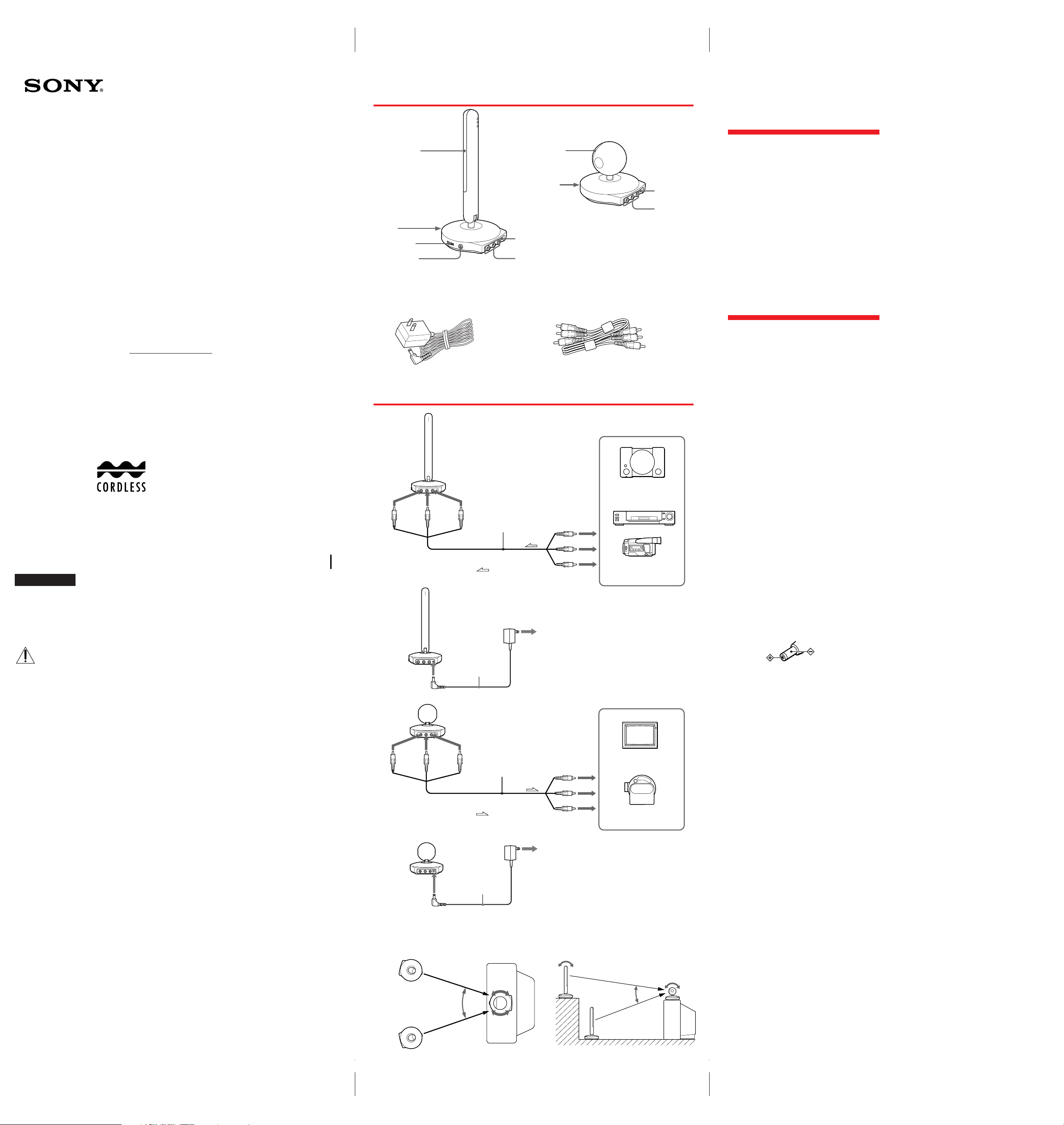
a Transmitter
Light emitter
POWER ON/OFF
switch
VOL control
PHONES jack
b Receiver
Light receiver
POWER ON/
OFF switch
DC IN 9V jack
Visual/Audio
input jacks
c AC power adapters d AV connecting cord
× 2
B
a
to Audio
input
jack
(Red)
Transmitter
(rear side)
to Visual
input
jack
(Yellow)(White)
AV connecting cord
to Visual
output
(Yellow)
(Red)
Video game
DC IN 9V
Visual/Audio
output jacks
Features
The IFV-TR1K is an AV cordless system which uses
infrared rays. Connect the transmitter to video
equipment such as a camcorder or video game, and the
receiver to a TV. You can enjoy playing back your video
tape on TV without connecting between the TV and
video equipment.
Contents
Transmitter (1) (See fig. A-a)
The transmitter emits infrared rays to the receiver.
Receiver (1) (See fig. A-b)
The receiver receives infrared rays from the transmitter.
AC power adapters (2) (See fig. A-c)
These adapters supply house current to the receiver
and the transmitter.
AV connecting cord (1) (See fig. A-d)
Connecting the transmitter to video equipment such as
a camcorder or video game.
Connecting the receiver to a TV (or a monitor).
Preparations
Preparing the transmitter
1 Connect the transmitter to video
equipment such as a camcorder or video
game with AV connecting cord.
(See fig.B–a)
2 Connect the supplied AC power adapter
to DC IN 9V of the transmitter.
(See fig.B–b)
3 Connect the supplied AC power adapter
to an AC outlet.
Preparing the receiver
1 Connect the receiver to a TV with the
supplied AV connecting cord.
(See fig.B–c)
2 Connect the supplied AC power adapter
to DC IN 9V of the receiver. (See fig.B–d)
3 Connect the supplied AC power adapter
to an AC outlet.
The receiver can face up, down, left or
right, and the transmitter can face
upwards as needed.
(See fig.B–e, f)
WARNING
To prevent fire or shock hazard, do
not expose the unit to rain or
moisture.
For the customers in the U.S.A.
This symbol is intended to alert the user to
the presence of important operating and
maintenance (servicing) instructions in the
literature accompanying the appliance.
WARNING
This equipment has been tested and found to comply
with the limits for a Class B digital device, pursuant to
Part 15 of the FCC Rules. These limits are designed to
provide reasonable protection against harmful
interference in a residential installation. This
equipment generates, uses, and can radiate radio
frequency energy and, if not installed and used in
accordance with the instructions, may cause harmful
interference to radio communications. However, there
is no guarantee that interference will not occur in a
particular installation. If this equipment does cause
harmful interference to radio or television reception,
which can be determined by turning the equipment off
and on, the user is encouraged to try to correct the
interference by one or more of the following measures:
– Reorient or relocate the receiving antenna.
– Increase the separation between the equipment and
receiver.
– Connect the equipment into an outlet on a circuit
different from that to which the receiver is connected.
– Consult the dealer or an experienced radio/TV
technician for help.
For the customers in Canada
CAUTION
TO PREVENT ELECTRIC SHOCK, DO NOT USE THIS
POLARIZED AC PLUG WITH AN EXTENSION
CORD, RECEPTACLE OR OTHER OUTLET UNLESS
THE BLADES CAN BE FULLY INSERTED TO
PREVENT BLADE EXPOSURE.
AC power cord plug
One blade of the plug is wider than the other for the
purpose of safety and will fit into the power outlet only
one way. If you are unable to insert the plug fully into
the outlet, contact your dealer.
b
to DC IN 9V jack
c
to Audio
output
jack
d
Transmitter
(rear side)
Receiver
(rear side)
to Visual
output
jack
(Yellow)(Red) (White)
Receiver
(rear side)
AC power
adapter
(supplied)
: Signal flow
AV connecting
cord (supplied)
: Signal flow
(White)
to Audio
output
to AC outlet
to Visual
input
(Yellow)
(Red)
(White)
to Audio
input
to AC outlet
Camcorder
TV
Projector
If your TV or VCR is a monaural type
Connect the yellow plug for video and connect only the
white plug for audio on both the receiver and the TV or
VCR. With this connection, the sound is monaural.
Notes
• To connect the receiver to an AC outlet, use only supplied
AC power adapter, because the polarity of the supplied
adapter is opposite of conventional adapters. Do not use
the supplied AC power adapter for other electric
appliances with a DC IN 9 V jack.
Polarity of the plug
• To connect more than one appliance to the transmitter,
use an AV selector such as the SB-V30G, SB-V40, etc.
(optional).
You are cautioned that any changes or modifications
not expressly approved in this manual could void your
authority to operate this equipment.
AC power
30°
adapter
(supplied)
Receiver
Side view
Transmitter
Receiver
30°
to DC IN 9V jack
ef
Top view
Transmitter
IFV-TR1K.3-859-271-11(1).E
Page 2
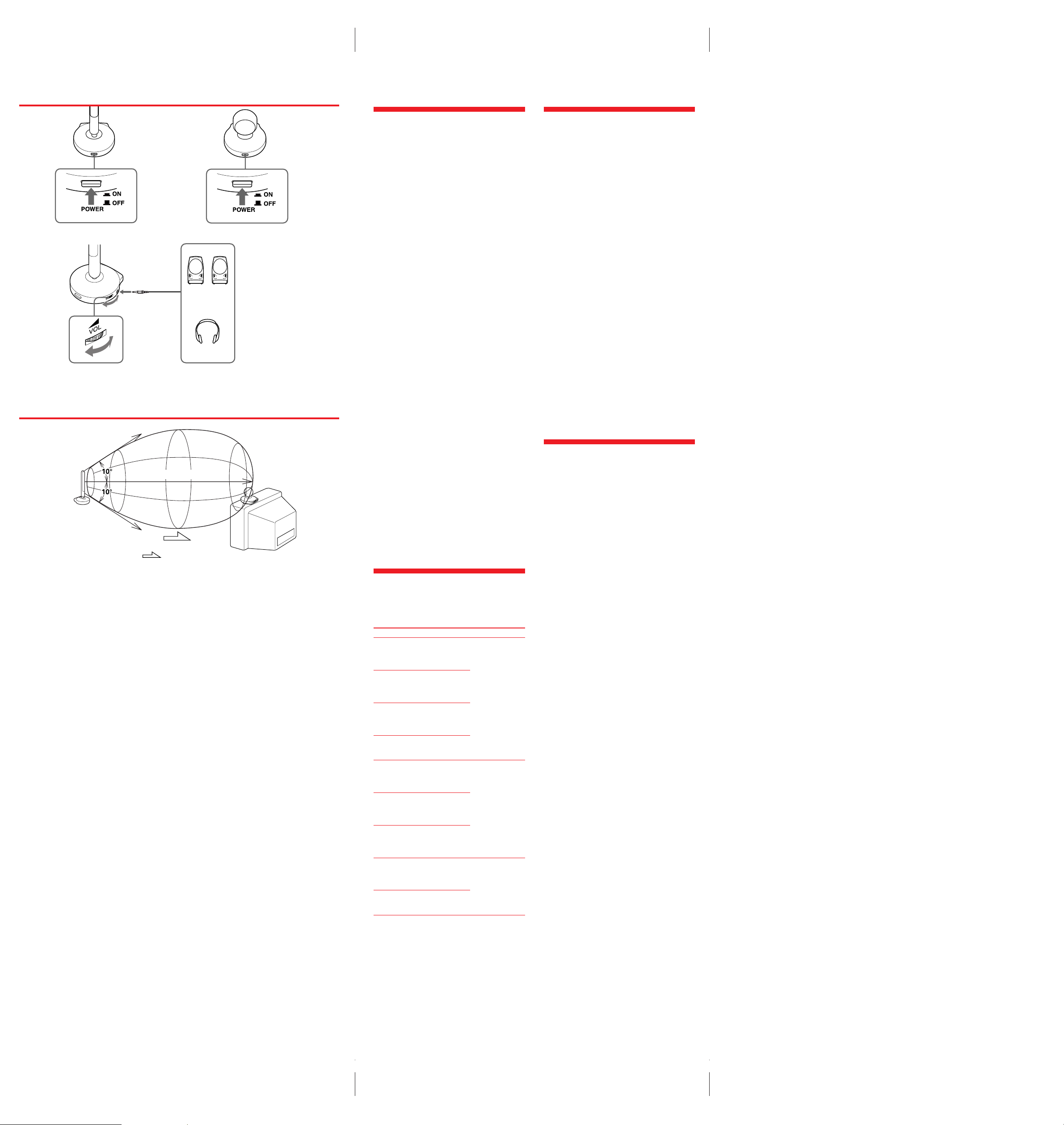
C
ab
c
Transmitter
to PHONES
Active Speaker
Headphones
E
Transmitter
Approx. 5 m (16 ft.)
: Signal flow
Receiver
Using This System
The following example details the connection of the
transmitter to a camcorder.
Please refer to the operation manual supplied with
your video equipment such as camcorder or video
game.
1 Turn on the camcorder or the video game
connected to the transmitter.
2 Press POWER on the receiver to turn it on
(OON). (See fig.C–a)
3 Turn the TV on.
4 Set the POWER switch on the transmitter
to ON. (See fig.C–b)
5 Start the playback by turning on the
camcorder or the video game.
6 Adjust the angle and direction of both the
transmitter and receiver.
Make sure that the infrared receiver and the
transmitter face each other when you use the
system.
Using a headphones (See fig.C–c)
Connect the headphones to the PHONES jack.
Adjust the volume with the VOL control.
After using this system
Press POWER on the transmitter and the receiver to
turn them off (o OFF). The Power lamp goes off.
Coverage of the infrared rays
(See fig.E)
The diagrams illustrate the approximate area covered
by the infrared rays. Position the transmitter and the
receiver within the area so that the units operate
effectively.
Notes
• Select the input of the receiver with the input selector on
the TV.
• If the angle of the transmitter or receiver is adjusted past
the movable range as illustrated, it can cause a
malfunction.
• Do not cover the light emitter or receiver of the
transmitter or the receiver with your hand, etc.
• The infrared rays will not penetrate walls or opaque
glass. Therefore, the infrared receiver must be used
within the “in sight” area of the transmitter.
• The brightness of the transmitter’s light emitter is not
necessarily stabilized. This is not a malfunction and does
not affect the infrared coverage distance.
• Noise and beats appears when the transmitter and the
receiver are positioned too close.
Troubleshooting
If you run into any problem using the system, first
check the power supply source. Then use the following
table for troubleshooting. Should the difficulty persist,
disconnect the power source and contact your Sony
dealer or local authorized Sony service facility.
Trouble Cause and/or remedy
No picture and
no sound at all.
The infrared
transmission
system does not
operate.
Background noise
and unclear picture.
The AC power adapter is not
connected to the the AC outlet.
n Connect the AC power adapter
to the AC outlet.
AV connecting cord is not
connected correctly.
n Connect the AV connecting cord
correctly.
The POWER of the transmitter is
turned off (OFF).
n Press the POWER button to turn
on the transmitter (ON).
Direct sunlight is shining on the
light receiver of the receiver.
n Avoid direct sunlight.
The POWER of the receiver is
turned off (OFF).
n Press the POWER button to turn
on the receiver (ON).
The transmitter and receiver are not
facing each other.
n Adjust the position and angle of
both units.
The receiver is positioned too far
from the transmitter.
n Use the transmitter near the
receiver.
The transmitter and receiver are not
facing each other.
n Adjust the position and angle of
both units.
Another infrared emitting
appliance is operating.
n Stop operating it.
Precautions
On safety
• Unplug the AC power adapter from the AC outlet
when it will not be used for a long period of time. To
disconnect the AC power adapter, pull it out by the
plug. Never pull the cord itself.
• Do not open the cabinet. Refer servicing to qualified
personnel only.
• Be sure that nothing metallic comes into contact with
the metal parts of the AC power adapter. If it does, a
short circuit may occur and the unit may be
damaged.
Operation
• Do not place the units in a location where it is:
– Extremely hot or cold
– Dusty or dirty
– Very humid
– Vibrating
• Do not apply mechanical shock or drop the units.
• The units become warm during the use, but this does
not indicate a malfunction.
• Avoid exposing any part of the receiver’s light
receiver to strong rays such as direct sunlight or
inverter fluorescent lamp rays or to another infrared
ray source such as a remote commander.
• Do not place any obstructions between the
transmitter and receiver, or the visual and sound will
disappear.
• Do not use this system with another infrared ray
transmitter such as cordless headphones or two pairs
of this system at the same time.
The signals may become mixed.
On cleaning and care
• Clean the units with a soft cloth slightly moistened
with water or mild detergent solution.
• Do not use alcohol, benzine or thinner to clean the
units, as they may mar the finish.
Specifications
Transmitter
Video input Pin jack (1): 1 Vp-p, 75 ohms,
Audio input Pin Jack (2: L, R): –10 dBs,
Audio output Stereo mini jack
Operating temperature
Storage temperature –20°C to 60°C (–4°F to 140°F)
Dimensions Approx. 95 x 230 x 100 mm (3
Mass Approx. 130 g (4.6 oz)
Receiver
Video output Pin jack (1): 1 Vp-p, 75 ohms,
Audio output Pin jack (2: L, R): –10 dBs,
Operating temperature
Storage temperature –20°C to 60°C (–4°F to 140°F)
Dimensions Approx. 95 x 95 x 100 mm (3
Mass Approx. 130 g (4.6 oz)
AC power adapter
Input AC 120 V 60 Hz
Output DC 9 V 600 mA
Supplied accessories AC power adapter (2)
Design and specifications are subject to change without
notice.
unbalanced, sync negative
Input impedance: more than
47 kilohms
0°C to 40°C (32°F to 104°F)
3
3
/
/4 x
x 9 1/8 x 4 inches) (w/h/d) (jack
and projected parts not included)
unbalanced, sync negative (When
POWER is ON)
Output impedance: less than
10 kilohms (When POWER is
ON)
0°C to 40°C (32°F to 104°F)
3
/4 x 4 inches) (w/h/d) (jack
3
and projected parts not included)
AV connecting cord (1)
4
IFV-TR1K.3-859-271-11(1).E
 Loading...