

Sony MVS-7000X, MKS-X7018, MVS-8000X, MKS-X7017, MKS-X7019 User Manual
...
MVS-8000X
MVS-7000X
ICP-X7000
MKS-X7075
MKS-X7011
MKS-X7017
MKS-X7018
MKS-X7019
MKS-X7020
MKS-X7024
MKS-X7026
MKS-X7031TB
MKS-X7033
MKS-X7035
MKS-X7040
MKS-X7041
MKS-X2700
MKS-X7700
MKS-X7701
MKS-X7702
USO RESTRITO
Multi Format Switcher System
MVS-8000X System
MVS-7000X System
(With ICP-X7000 Integrated Control Panel Version 1.0)
User’s Guide [English]
Software Version 12.50 and Later
1st Edition

NOTICE TO USERS
USO RESTRITO
© 2014 Sony Corporation. All rights reserved. This
manual or the software described herein, in whole or
in part, may not be reproduced, translated or reduced
to any machine readable form without prior written
approval from Sony Corporation.
SONY CORPORATION PROVIDES NO
WARRANTY WITH REGARD TO THIS MANUAL,
THE SOFTWARE OR OTHER INFORMATION
CONTAINED HEREIN AND HEREBY EXPRESSLY
DISCLAIMS ANY IMPLIED WARRANTIES OF
MERCHANTABILITY OR FITNESS FOR ANY
PARTICULAR PURPOSE WITH REGARD TO THIS
MANUAL, THE SOFTWARE OR SUCH OTHER
INFORMATION. IN NO EVENT SHALL SONY
CORPORATION BE LIABLE FOR ANY
INCIDENTAL, CONSEQUENTIAL OR SPECIAL
DAMAGES, WHETHER BASED ON TORT,
CONTRACT, OR OTHERWISE, ARISING OUT OF
OR IN CONNECTION WITH THIS MANUAL, THE
SOFTWARE OR OTHER INFORMATION
CONTAINED HEREIN OR THE USE THEREOF.
Sony Corporation reserves the right to make any
modification to this manual or the information
contained herein at any time without notice.
The software described herein may also be governed
by the terms of a separate user license agreement.

3
USO RESTRITO
Table of Contents
Chapter 1 Overview
Introduction............................................... 16
Features .................................................... 17
Basic Video Processing ........................... 18
Transition..................................................... 18
Keys ............................................................. 20
Wipes ........................................................... 20
DME Wipes ................................................. 21
Frame Memory ............................................ 21
Color Backgrounds ...................................... 21
Copy and Swap ............................................ 21
Video Process .............................................. 21
Color Corrector............................................ 21
Side Flags .................................................... 21
Multi Program 2 .......................................... 22
4K Support .................................................. 23
Creation of Special Effects and
Management of Data and
Operations .......................................... 23
Digital Multi Effects (DME) ....................... 23
External Device Control .............................. 24
Keyframes ................................................... 24
Snapshots ..................................................... 24
Utility........................................................... 24
Shotbox ........................................................ 24
Macros ......................................................... 24
File Operations ............................................ 25
Setup ......................................................... 25
System Configuration .............................. 26
System Configuration Example ................... 26
Control Panel Connection Example ............ 27
Chapter 2 Menus and Control Panel
Names and Functions of Parts of the
Control Panel ..................................... 28
Control Panel Configuration ....................... 28
Cross-Point Control Block .......................... 29
Transition Control Block ............................. 33
Flexi Pad Control Block .............................. 36
Key Control Block ....................................... 37
Device Control Block (Trackball) ............... 40
Numeric Keypad Control Block .................. 43
Utility/Shotbox Control Block .................... 45
AUX Bus Control Block ............................. 46
Menu Panel .................................................. 49
Names and Functions of Parts of the
Menu Screen ................................ ....... 50
Overview ..................................................... 50
Top Menu List ............................................. 50
Menu Screen ................................................ 50
Top Menu Window ...................................... 53
Numeric Keypad Window ........................... 54
Keyboard Window ....................................... 55
Color Palette Window ................................. 56
Basic Menu Operations ............................ 57
Recalling a Menu ......................................... 57
Selecting a Menu ......................................... 57
Selecting a List Item .................................... 57
Setting Parameters ....................................... 57
Returning Settings to Default Values .......... 58
Using a Mouse ............................................. 58
Using the Shortcut Menu ............................. 58
Switching between the Main Menu Site and
Sub Menu Site .................................. 59
Shutting Down the Menu ............................. 59
Shutting Down the Switcher System ........... 60
Power Supply and Connector Section .... 61
MKS-X2700/X7700 System Interface
Unit..................................................... 61
Control Panel ............................................... 65
MKS-X7011 Menu Panel ............................ 66
Chapter 3 Signal Selection and
Transitions
Image Creation Operation Flow ............... 67
Signal Selection ........................................ 68
Overview ..................................................... 69

4
Bus Selection ............................................... 69
USO RESTRITO
Signal Assignment and Selection ................ 72
Inhibiting Operation of Cross-point
Buttons ............................................... 73
Signal Name Display ................................... 74
Transitions ................................................ 74
Transition Type ........................................... 74
Basic Operation for Transitions .............. 75
Key Priority Settings ................................ 77
Setting the Key Priority (Transition Control
Block) ............................................... 77
Key Priority Setting Operations (Menu)...... 78
Displaying the Key Output Status and
Priority ............................................. 78
Selecting the Transition Type (Menu) ..... 79
Super Mix Settings ...................................... 79
Preset Color Mix Settings ............................ 79
Executing a Transition ............................. 81
Transition Indicator ..................................... 81
Setting the Transition Rate .......................... 81
Pattern Limit ................................................ 83
Executing an Auto Transition ...................... 85
Executing a Transition with the Fader Lever
(Manual Transition) ......................... 85
Auto/Manual Transition Combination ........ 86
Non-Sync State ............................................ 86
Fader Lever Operation in Bus Fixed
Mode .................................................. 87
Transition Preview .................................... 88
Independent Key Transitions .................. 89
Overview ..................................................... 89
Basic Independent Key Transition
Operations .......................................... 91
Selecting Independent Key Transition
Type ................................................... 92
Setting the Independent Key Transition
Rate .................................................... 92
Fade-to-Black ............................................ 93
AUX Mix Transitions ................................. 94
Chapter 4 Keys
Overview .................................................... 95
Key Types .................................................... 95
Key Modifiers .............................................. 96
Key Memory ................................................ 97
Key Defaults ................................................ 97
Key Setting Operations (Menu) ................ 98
Key Setting Menus ...................................... 98
Setting the Key Type ................................... 98
Selecting Key Fill and Key Source .............. 99
Chroma Key Composition and Settings .... 100
Key Adjustments (Menu) ........................ 102
Chroma Key Adjustments .......................... 102
Key Edge Modification ............................. 104
Mask .......................................................... 107
DME Effects for Keys ............................... 109
Specifying the Key Output Destination ..... 111
Blink .......................................................... 111
Video Process ............................................ 111
Key Modify Clear ...................................... 112
Key Operations (Key Control Block) ..... 112
Selecting the Bank and Keyer .................... 112
Setting the Key Type ................................. 113
Selecting a Key Fill ................................... 113
Key Source Selection ................................. 114
Key Adjustments (Key Control
Block) ................................................ 114
Key Edge Modification ............................. 114
DME Effects for Keys ............................... 115
Other Key Adjustments ............................. 116
Resizer ..................................................... 117
Two-Dimensional Transforms and
Rotation of Keys .............................. 117
Interpolation Settings ................................. 119
Crop/Border Settings ................................. 119
Effect Settings ............................................ 121
Setting Rotation ......................................... 123
Key Snapshots ........................................ 124
Key Snapshot Operations ........................... 124

5
Chapter 5 Wipes
USO RESTRITO
Overview .................................................. 125
Types of Wipe Pattern ............................... 125
Basic Wipe Setting Operations.............. 125
Selecting a Wipe Pattern ............................ 125
Pattern Mix ................................................ 126
Setting Wipe Modifiers ............................. 128
Wipe Modify Clear .................................... 134
Basic Independent Key Transition Wipe
Setting Operations ........................... 134
Selecting an Independent Key Transition
Wipe Pattern ..................................... 134
Setting Independent Key Transition Wipe
Modifiers .......................................... 134
Wipe Snapshots ...................................... 136
Wipe Snapshot Operations (Flexi Pad Control
Block) ............................................... 136
Wipe Snapshot Operations (Menu)............ 137
Chapter 6 DME Wipes
Overview .................................................. 138
Types of DME Wipe Patterns .................... 138
DME Wipe Pattern Variation and
Modifiers .......................................... 141
DME Wipe Restrictions ............................ 141
Basic DME Wipe Setting Operations ..... 143
Selecting a DME Wipe Pattern .................. 143
Setting DME Wipe Modifiers ................... 144
DME Wipe Modify Clear .......................... 147
Basic Independent Key Transition DME
Wipe Setting Operations ................. 147
Selecting an Independent Key Transition
Wipe Pattern ..................................... 147
Setting Independent Key Transition DME
Wipe Modifiers ................................ 147
DME Wipe Snapshots ............................. 149
DME Wipe Snapshot Operations (Flexi Pad
Control Block) ................................. 149
DME Wipe Snapshot Operations
(Menu).............................................. 149
Creating User Programmable DME
Patterns ........................................... 150
User Programmable DME Transition
Mode ................................................ 150
Chapter 7 Frame Memory
Overview .................................................. 153
Still Image File Operations ..................... 155
Preparations ............................................... 155
Frame Memory Menu Layout.................... 155
Selecting an Input Image ........................... 157
Selecting Outputs and Target Frame
Memory ............................................ 157
Capturing and Saving an Input Image
(Store)............................................... 158
Recalling Still Images (Recall) .................. 159
Image Output ............................................. 160
Continuously Capturing Still Images (Record)
......................................................... 161
Recalling a Continuous Sequence of Still
Images (Animation) ........................ 161
Frame Memory Clip Function ................. 163
Frame Memory Clip Operations ............. 164
Preparations ............................................... 164
Recalling Clips (Recall) ............................ 164
Clip Playback ............................................. 165
Clip Creation ............................................. 166
Creating and Managing Frame Memory
Folders ............................................ 166
Clip Output ................................................ 167
Recording and Playback of Ancillary
Data .................................................. 167
Clip Transition Operations ..................... 168
Clip Transition Settings ............................. 168
Image Data Management ........................ 170
Pair File Processing ................................... 170
Moving Files .............................................. 170
Deleting Files ............................................. 170
Renaming Files .......................................... 171
Using an External HDD ........................... 171
Formatting a HDD ..................................... 172
Saving Files ............................................... 172

6
Loading Files ............................................. 172
USO RESTRITO
Managing Images using a DDR/VTR ..... 173
High-speed Backup and Restoring ............ 173
Extracting Images from Video Tape ......... 174
Chapter 8 Color Backgrounds, Copy
and Swap, and Other Settings
Color Backgrounds ................................ 176
Basic Color Background Setting
Operations ........................................ 176
Copy and Swap ....................................... 177
Overview ................................................... 177
Basic Copy and Swap Operations ............. 179
Misc Menu ............................................... 180
Control Port Settings from an External
Device ............................................ 180
Setting the Safe Title Area ........................ 180
Displaying a List of Transition Rates and
Changing the Settings .................... 180
Setting the AUX Mix Transition Rate ....... 181
AUX Menu ............................................... 182
Setting the Video Process for an AUX
Bus ................................................... 182
Setting the Color Corrector for an AUX
Bus ................................................... 182
Status Menu ............................................ 183
Router Menu............................................ 183
Destination Input List Display .................. 183
Switching the Source for a Destination ..... 183
Video Process ......................................... 184
Overview ................................................... 184
Video Process Memory ............................. 185
Setting the Video Process .......................... 185
Chapter 9 Color Corrector
Setting Color Corrector Functions ........ 188
Input Video Process ................................... 188
Primary Color Correction .......................... 188
Secondary Color Correction ...................... 189
Luminance Process .................................... 190
Spot Color Adjustment .............................. 191
Output Video Process ................................ 192
YUV Clips ................................................. 192
RGB Clips ................................................. 193
Chapter 10 Special Functions
Side Flags ................................................ 194
Overview ................................................... 194
Side Flag Settings ...................................... 194
Wipe Action on Images with Side
Flags ................................................. 195
DME Wipe Action on Images with Side
Flags ............................................... 195
Multi Program 2 ....................................... 197
Overview ................................................... 197
Multi Program 2 Mode Settings (Basic
Operation) ...................................... 198
Multi Program 2 Mode Settings (Other
Operations) ..................................... 199
Functions Added in Multi Program 2
Mode ................................................ 201
Differences Between Multi Program 2 Mode
and Standard Mode ......................... 202
Multi Program 2 Mode Restrictions .......... 203
4K System ................................................ 204
Overview ................................................... 204
4K System Settings .................................... 204
4K System Restrictions ............................. 205
M/E Configuration Switching (M/E
Split) .................................................. 207
M/E Split Mode Settings ........................... 207
M/E Split Mode Restrictions ..................... 207
Overview ................................................. 186
Basic Color Corrector Operations......... 187
Setting a Color Corrector .......................... 187
Copy and Swap .......................................... 187

7
Chapter 11 DMEs
USO RESTRITO
Overview .................................................. 209
Devices Supporting DMEs ........................ 209
Transforms in Three-Dimensional Space
(Transforms) ..................................... 210
Transform Operation Modes ..................... 212
Graphics Display ....................................... 214
Three-Dimensional Parameter Display ...... 215
Special Effects ........................................... 215
Global Effects ............................................ 221
Three-Dimensional Transform
Operations ........................................ 222
Three-Dimensional Transform Basic
Operations ........................................ 222
Three-Dimensional Parameter Display ...... 224
Three-Dimensional Parameter Entry ......... 225
Graphics Display ....................................... 225
Virtual Image Cancelation ......................... 226
Applying Special Effects (Common
Operations) ....................................... 227
Applying Special Effects (Edge
Effects) .............................................. 227
Border Settings .......................................... 227
CG Border Settings ................................... 228
Crop Settings ............................................. 228
Beveled Edge Settings ............................... 229
Key Border Settings .................................. 230
Art Edge Settings ....................................... 230
Flex Shadow Settings ................................ 233
Wipe Crop Settings ................................... 236
Color Mix Settings .................................... 238
Applying Special Effects (Effects on the
Overall Signal) .................................. 239
Defocus Settings ........................................ 239
Blur Settings .............................................. 239
Multi Move Settings .................................. 240
Sepia Settings ............................................ 240
Mono Settings ............................................ 241
Posterization/Solarization Settings ............ 241
Nega Settings ............................................. 241
Contrast Settings ........................................ 241
Mosaic Settings ......................................... 242
Sketch Settings .......................................... 242
Metal Settings ............................................ 243
Dim and Fade Settings ............................... 243
Glow Settings ............................................ 244
Mask Settings ............................................ 244
Freeze Settings ........................................... 245
Applying Special Effects (Nonlinear Effect
Settings) .......................................... 246
Wave Settings ............................................ 246
Mosaic Glass Settings................................ 248
Flag Settings .............................................. 248
Twist Settings ............................................ 248
Ripple Settings........................................... 249
Rings Settings ............................................ 251
Broken Glass Settings................................ 251
Flying Bar Settings .................................... 251
Blind Settings ............................................ 252
Split Settings .............................................. 252
Split Slide Settings .................................... 253
Mirror Settings ........................................... 253
Multi Mirror Settings ................................. 253
Kaleidoscope Settings ............................... 254
Lens Settings ............................................. 254
Circle Settings ........................................... 255
Panorama Settings ..................................... 255
Page Turn Settings ..................................... 255
Roll Settings .............................................. 256
Cylinder Settings ....................................... 256
Sphere Settings .......................................... 256
Explosion Settings ..................................... 256
Swirl Settings ............................................. 257
Melt Settings .............................................. 257
Character Trail Settings ............................. 258
Applying Special Effects (Lighting and
Recursive Effects) .......................... 259
Lighting Settings ....................................... 259
Trail Settings ............................................. 261
Motion Decay Settings .............................. 262
Keyframe Strobe Settings .......................... 263
Wind Settings ............................................ 264
Spotlighting Settings ................................. 265
Applying Special Effects (Other
Effects) .............................................. 272
Background Settings .................................. 272
Separate Sides Settings .............................. 272

8
Shaped Video Settings............................... 272
USO RESTRITO
Invert Settings............................................ 273
Key Density Settings ................................. 274
Key Source Selection ................................ 274
Interpolation Settings ................................ 274
Corner Pinning Settings ............................. 275
Global Effects ......................................... 277
Overview ................................................... 277
Combiner Settings ..................................... 277
Brick Settings ............................................ 280
Shadow Settings ........................................ 281
Chapter 12 External Devices
Control of External Devices ................... 283
Shared Functions for External Device
Control ............................................. 283
Control of P-Bus Devices ...................... 284
Creating and Editing the P-Bus
Timeline ........................................... 284
P-Bus Trigger ............................................ 285
Control of GPI Devices ........................... 286
Creating and Editing the GPI Timeline ..... 286
Control of VTRs, Disk Recorders, and
Extended VTRs ............................... 288
Controlling the Tape/Disk Transport ......... 288
Displaying VTR/Disk Recorder/Extended
VTR Information ........................... 290
Cueup & Play ............................................ 291
VTR/Disk Recorder/Extended VTR
Timeline ........................................... 293
Disk Recorder/Extended VTR File
Operations ...................................... 295
Chapter 13 Keyframes
Regions ................................................... 297
Registers ................................................. 298
Keyframes ............................................... 298
Effects ........................................................ 298
Saving and Recalling Effects..................... 298
Effect Attributes ........................................ 298
Effect Editing ............................................. 299
Time Settings ............................................. 299
Paths .......................................................... 300
Effect Execution ........................................ 303
Master Timelines ....................................... 303
Sequence of Keyframe Operations ............ 303
Displaying the Timeline Menu ................ 305
Interpreting the Timeline Menu ................. 305
Timeline Menu Display Settings ............... 306
Recalling a Register ................................ 307
Recalling a Register (Numeric Keypad
Control Block) ................................ 307
Specifying the Region and Edit
Points ................................................ 309
Region Selection ........................................ 309
Edit Point Specification ............................. 309
Creating and Editing Keyframes ............ 310
Creating Keyframes ................................... 310
Inserting Keyframes .................................. 311
Modifying Keyframes ............................... 311
Deleting Keyframes ................................... 312
Moving Keyframes .................................... 313
Copying Keyframes ................................... 313
Pause .......................................................... 313
Keyframe Loop (Repeated Execution of a
Specified Range) ............................ 313
Undoing an Edit Operation ........................ 315
Duration Mode Setting .............................. 315
Transition Mode Settings for User
Programmable DME ...................... 315
Time Settings .......................................... 318
Setting the Keyframe Duration .................. 318
Setting the Effect Duration ........................ 318
Delay Setting ............................................. 318
Path Settings ........................................... 319
Basic Path Setting Operations ................... 319
Effect Execution ................................ ...... 321
Effect Execution (Utility/Shotbox Control
Block) ............................................. 321
Setting the Run Mode ................................ 321
Saving Effects ......................................... 322
Creating and Saving a Master Timeline 323

9
Creating and Saving a Master Timeline
USO RESTRITO
(Numeric Keypad Control Block) .. 323
Creating and Saving a Master Timeline
(Menu) ............................................ 324
Recalling and Executing a Master
Timeline ............................................ 325
Recalling and Executing a Master Timeline
(Flexi Pad Control Block) .............. 325
Editing Registers .................................... 326
Effect Status Display ................................. 326
Effect Attribute Settings ............................ 326
Effect Register Editing .............................. 327
Effect Register List View and Editing ....... 328
Chapter 14 Snapshots
Overview ................................................. 330
Snapshot Types .......................................... 330
Snapshot Attributes ................................... 330
Snapshot Operations (Numeric Keypad
Control Block) ................................. 331
Saving and Recalling Snapshots ................ 331
Snapshot Operations (Flexi Pad Control
Block) ............................................... 333
Banks and Registers .................................. 333
Saving and Recalling Snapshots ................ 334
Snapshot Operations (Menu) ................. 336
Selecting a Region or Reference Region...336
Setting Snapshot Attributes ..................... 336
Snapshot Status Display ............................ 337
Setting Key Snapshot Attributes ............... 338
Creating and Saving a Master Snapshot .... 338
Snapshot Register Editing ......................... 338
Snapshot Register List View and
Editing ............................................ 338
Operations in the Misc >Snapshot Menu on a
Switcher Bank ................................ 339
Chapter 15 Utility/Shotbox
Utility Overview ....................................... 340
Utility Execution ..................................... 340
Utility Execution (Menu Panel) ................. 340
Utility Execution (Utility/Shotbox Control
Block) ............................................. 341
Utility Execution (Cross-Point Control
Block) ............................................. 341
Shotbox Overview ................................... 342
Shotbox Register Creation ..................... 343
Shotbox Register Creation (Numeric Keypad
Control Block) ................................ 343
Shotbox Register Creation (Menu) ............ 344
Shotbox Execution .................................. 345
Shotbox Execution (Numeric Keypad Control
Block) ............................................. 345
Shotbox Execution (Flexi Pad Control Block)
......................................................... 345
Shotbox Execution (Utility/Shotbox Control
Block) ............................................. 346
Shotbox Execution (Cross-Point Control
Block) ............................................. 346
Shotbox Register Editing ....................... 347
Chapter 16 Macros
Macros ..................................................... 348
Overview ................................................... 348
Macro Creation and Editing ...................... 349
Macro Execution ....................................... 350
Macro Operations (Numeric Keypad
Control Block and Utility/Shotbox
Control Block) ................................. 351
Recalling a Macro Register and Executing a
Macro ............................................. 351
Macro Creation and Editing ...................... 352
Saving a Macro .......................................... 355
Macro Operations (Flexi Pad Control
Block) .............................................. 356
Recalling a Macro Register and Executing a
Macro ............................................. 356
Macro Creation and Editing ...................... 357
Saving a Macro .......................................... 358
Deleting a Macro ....................................... 358
Macro Operations (Cross-Point Control
Block) .............................................. 359
Macro Operations (Menu) ....................... 360

10
Macro Register Editing ............................. 360
USO RESTRITO
Online Editing of Macro Events ................ 360
Offline Editing of Macro Events ............... 362
Macro Attachments ................................ 365
Setting and Canceling a Macro
Attachment ....................................... 365
Displaying the Macro Attachment
Settings ........................................... 368
Executing a Macro by Macro
Attachment ....................................... 368
Menu Macros........................................... 369
Recalling a Menu Macro Register and
Executing a Menu Macro ............... 369
Creating and Editing a Menu Macro ......... 371
Menu Macro Register Editing ................... 373
Macro Timeline ....................................... 373
Creating and Editing a Macro Timeline .... 374
Chapter 17 Files
Overview of File Operations .................. 375
Operations on Individual Files .............. 378
Detailed File Information .......................... 378
Region Selection........................................ 378
Selecting a Device for Operation .............. 379
Saving Files ............................................... 379
Loading Files ............................................. 380
Copying Files ............................................ 380
Renaming Files .......................................... 381
Deleting Files ............................................ 381
Interconversion of Frame Memory Clips and
Extended Clips ............................... 382
Creating Frame Memory Folders .............. 382
Saving a Frame Memory File List ............. 383
Batch File Operations ............................ 383
Saving Files in Batch ................................. 383
Loading Files in Batch .............................. 384
Copying Files in Batch .............................. 384
Importing and Exporting Files ............... 385
Importing Frame Memory Data................. 385
Exporting Frame Memory Data................. 385
Directory Operations .............................. 386
Creating a Directory .................................. 386
Renaming a Directory ................................ 386
Protecting (Write Inhibit) a Directory ....... 386
Deleting a Directory .................................. 387
Copying Files Between Unit IDs/Group
IDs .................................................... 387
Copying Files Between Different Unit
IDs .................................................. 387
Copying Files Between Different Group IDs
387
Saving Files Loaded by Autoload .......... 388
Chapter 18 System Setup
Settings Relating to the Network ........... 390
Setting the Group ID and Unit ID of the Menu
Panel ............................................... 390
Authenticating IP Addresses Automatically ..
390
Configuring the NFS Server ...................... 390
Settings Relating to System Configuration
.......................................................... 391
Selecting the Operation Mode ................... 391
Specifying the Switcher Controlled by the
Control Panel .................................. 391
Specifying the DME to Connect to the
Switcher ......................................... 391
Enabling the FM Data Port of the
Switcher ........................................... 392
Settings Relating to Signal Formats ...... 392
Setting the Signal Format .......................... 392
Enabling Passage of 59.94 (2x) Format
Signals on an AUX Bus ................. 393
Switching the Input Reference Signal for HD
System ............................................ 393
Setting Conversion Formats (Format
Converter) ...................................... 394
Setting Conversion Formats (4K Up-
Converter) ...................................... 396
Switching the Screen Aspect Ratio ........... 396
Power-On (Startup) State Selection ....... 397
Saving and Recalling Setup Data .............. 398
Selecting the Startup State ......................... 398
Saving User-Defined Settings ................... 398

11
Setting Automatic Loading of Register Data at
USO RESTRITO
Power On (Autoload Function) ...... 398
Reset and Initialization ........................... 399
Settings Relating to Installation and
Devices ............................................ 399
Displaying Installation Detail
Information ...................................... 399
Installing Software .................................... 399
Configuring Settings to Use the
Software ........................................... 400
Adding User Texture Patterns ................... 401
Registering a Frame Memory Clip with
Ancillary Data ................................ 404
Setting the DME Input/Output Signal
Format .............................................. 404
Setting the Number of DMEs to Connect to the
Switcher ......................................... 405
Settings Relating to Device
Management ..................................... 405
Setting the Date and Time ......................... 405
Using a Removable Drive ......................... 405
Setting a Removable Drive as the Primary
Device ............................................ 406
Initializing the Local Drive ....................... 406
Locking Setup Menu Settings ................... 406
Locking File Loading Operations .............. 407
Chapter 19 Control Panel Setup
Settings Relating to Control Panel
Configuration .................................. 408
Setting the Configuration for Each
Bank ................................................. 408
Inhibiting Operation on a Bank ................. 408
Assigning a Single M/E to Two M/E
Banks................................................ 408
Linking Switcher Bus and Router
Destinations .................................... 409
Linking Transitions Between Keyers ........ 410
Assigning a Region to the Region Selection
Buttons in the Numeric Keypad Control
Block .............................................. 410
Setting Transition Control Block Button
Assignments ................................... 411
Setting Flexi Pad Control Block Button
Assignments ................................... 411
Setting Utility/Shotbox Control Block Button
Assignments ................................... 411
Setting Device Control Block (Trackball)
Button Assignments ....................... 412
Setting Menu Panel Button
Assignments ..................................... 412
Inhibiting Utility 2 Bus and Key
Operations ........................................ 412
Inhibiting DME Channel Selection
Operations ...................................... 413
Cross-Point Settings ............................... 413
Creating Cross-Point Assign Tables .......... 413
Copying Cross-Point Assign Tables .......... 415
Selecting Cross-Point Assign Tables ......... 416
Exporting Source Names and Destination
Names ............................................. 416
Assigning the [SIDE FLAG] Button ......... 416
AUX Bus Control Block Settings ........... 417
Setting the AUX Bus Block ....................... 417
Configuring Router Control ...................... 417
Settings Relating to Button
Assignment ..................................... 418
Assigning Functions to User Preference
Buttons ........................................... 418
Assigning a Function to a Memory Recall
Button in the Utility/Shotbox Control
Block .............................................. 421
Assigning Functions to 1st Row/2nd Row
Buttons of the Cross-Point Control
Block .............................................. 425
Settings Relating to External Device
Connections .................................... 426
Setting the Control Mode for P-Bus
Devices ........................................... 426
Associating a Serial Port with a Device
Selection Button ............................. 426
Setting the AUX Bus Override Operation
Mode .............................................. 426
Settings Relating to Operation............... 427
Setting the On-Air Tally ............................ 427
Setting the Transition Rate Display
Mode ................................................ 427
Setting the Transition Indicator Display in
Non-Sync State .............................. 427

12
Configuring Settings Relating to
USO RESTRITO
Effects .............................................. 427
Setting Source Names and Destination
Names .............................................. 428
Setting Flexi Pad Control Block Button
Display and Operation ...................... 428
Setting the Button Operation Mode ........... 428
Setting the Operation Mode of the [ALL]
Button in the Transition Control
Block ................................................ 429
Setting Device Control Block Button and
Trackball Operation ......................... 429
Setting the Macro Execution Mode ........... 429
Setting Button and Indicator Status on the
Cross-point Control Block/AUX Bus
Control Block ................................... 430
Configuring the Cross-Point Flexi Pad...... 430
Settings Relating to Control Panel
Management ..................................... 432
Setting the Screen Saver ............................ 432
Setting Panel Sleep Mode .......................... 432
Adjusting the Brightness ........................... 432
Setting the State of Buttons that are Not
Lit ..................................................... 432
Setting Beep Sound for Touch
Operation.......................................... 432
Calibrating the Touch Panel ...................... 432
Setting the Menu to Display at Startup ..... 432
Setting the Mouse Wheel Function when
Setting Parameters ........................... 433
Setting the Mouse Button Function when
Setting Parameters ........................... 433
Chapter 20 Switcher Setup
Switcher Configuration .......................... 434
Adjusting the Reference Phase .................. 434
Specifying the Video Switching Timing...434
Setting the Operation Mode ...................... 434
Setting User Regions ................................. 435
Assigning PGM/PST Logically to an
M/E .................................................. 435
Setting DME Channel Assignments .......... 436
Setting the Side Flag Material and Operation
436
Settings Relating to Signal Inputs ......... 437
Setting Through Mode ............................... 437
Setting the Video Process .......................... 437
Setting the Input Signal Color Corrector...438
Setting the Illegal Color Limiter .............. 438
Selecting the Primary Input to use as the
Format Converter ........................... 439
Setting the Frame Delay Function ............. 439
Selecting the Format Converter
Conversion Method .......................... 439
Setting the IP Converter Conversion
Method ............................................. 441
Setting the 4K Up-Converter Conversion
Method ........................................... 442
Settings Relating to Signal Outputs ...... 443
Assigning Output Signals .......................... 443
Adjusting Video Clips ............................... 443
Setting Vertical Blanking Interval Adjustment
and Through Mode ......................... 443
Setting the Safe Title Area......................... 444
Cropping a 4:3 Mode Image in an HD
system............................................... 444
Setting Format Converter Outputs ............. 444
Configuring Multi Viewer ......................... 444
Enabling AUX Mix Transitions ................ 446
Settings Relating to Video Switching .... 446
Selecting the Bank to Configure ................ 446
Settings Relating to Keys, Wipes, Frame
Memory, and Color Correction ...... 447
Enabling the Input Signal and AUX Bus Color
Corrector ........................................ 447
Setting the Video Process Memory ........... 448
Setting Show Key ...................................... 448
Setting the Key Auto Drop Function ......... 448
Automatically Naming when Saving to Frame
Memory .......................................... 448
Selecting the Bank to Configure ................ 448
Settings Relating to Function Links ...... 450
Setting a Cross-Point Button Link ............. 450
Setting a Link Table .................................. 450
Linking Cross-Point Buttons and GPI Output
Ports ............................................... 450
Setting a Link Between M/E Banks .......... 451

13
Setting Key Transition Links .................... 451
USO RESTRITO
Settings Relating to External Device
Connections .................................... 452
Setting the 9-Pin Port Device Interface ..... 452
Setting Switcher GPI Inputs ...................... 452
Setting Switcher GPI Outputs ................... 454
Setting AUX Bus Control.......................... 454
Setting the Interface Between the DME and
the Switcher .................................... 455
Setting AUX Bus Outputs and Re-entry
Inputs .............................................. 455
Setting the Key Off Mode for Control from an
Editor .............................................. 455
Assigning a GPI Output Port ..................... 464
Releasing a GPI Output Port
Assignment....................................... 464
GPI Output Settings ................................ 465
Configuring GPI Outputs .......................... 465
Serial Port Settings ................................. 466
Configuring Serial Port Settings ................ 466
Configuring Detailed Settings for an
External Device Connected to
the Serial Port ................................... 466
Chapter 23 Router Interface and
Tally Setup
Chapter 21 DME Setup
Settings Relating to Signal Inputs ........ 457
Setting Initial Crop .................................... 457
Setting the Illegal Color Limiter for Matte
Signals ............................................ 457
Adjusting DME System Phase .................. 457
Setting the TBC Window Center
Position ............................................ 458
Settings Relating to Signal Outputs ..... 458
Adjusting the DME Output Video Clip
Level ................................................ 458
Setting the Monitor Output........................ 458
Settings Relating to External Device
Connections .................................... 459
Setting the Editor Protocol ........................ 459
Setting the Editor Port Mode ..................... 459
Setting DME GPI Inputs ........................... 459
Setting DME GPI Outputs ......................... 460
Chapter 22 DCU Setup
Parallel Input Settings ............................ 461
Assigning a GPI Input Port ....................... 461
Releasing a GPI Input Port Assignment .... 462
GPI Input Settings .................................. 462
Configuring GPI Inputs ............................. 462
Parallel Output Settings ......................... 464
Router Interface Settings ....................... 470
Assigning Switcher Inputs/Outputs to S-Bus
Space .............................................. 470
Setting External Boxes 1 to 12 .................. 470
Tally Group Settings ............................... 471
Wiring Settings ........................................ 472
Configuring Wiring ................................... 472
Modifying Wiring Settings ........................ 472
Deleting Wiring Settings ........................... 472
Sorting Wiring Settings ............................. 472
Tally Generation Settings ....................... 473
Configuring Tally Generation ................... 473
Modifying Tally Generation ...................... 473
Deleting Tally Generation ......................... 473
Tally Copy Settings ................................. 474
Configuring Tally Copy ............................ 474
Modifying Tally Copy ............................... 474
Deleting Tally Copy .................................. 474
Parallel Tally Settings ............................. 475
Configuring/Modifying Parallel Tally ....... 475
Deleting Parallel Tally ............................... 475
Serial Tally Settings ................................ 476
Configuring/Modifying Serial Tally .......... 476
Configuring the Serial Tally Source
Address............................................. 476
Clearing Source Address Settings ............. 476

14
Chapter 24 User Setup
USO RESTRITO
Source Patching ..................................... 477
Source Patching Operation Flow ............... 477
Exporting a User Source Name File to a
Removable Drive ............................. 477
Creating a Patch Table (Conversion
Table) ............................................... 477
Replacing Signal Pairs Using the Patch
Table ................................................ 478
Chapter 25 Diagnosis
Communications Status......................... 479
Communications Status Display................ 479
Appendix
Wipe Pattern List ................................ .... 480
Wipe Pattern List ....................................... 480
DME Wipe Pattern List ............................. 481
Resizer DME Wipe Pattern List ................ 486
Menu Tree................................................ 487
M/E-1 Menu .............................................. 487
PGM/PST Menu ........................................ 490
Color Bkgd Menu ...................................... 492
Aux Menu .................................................. 492
CCR Menu ................................................. 492
Frame Memory Menu ................................ 493
Copy/Swap Menu ...................................... 494
Misc Menu ................................................. 494
Status Menu ............................................... 494
DME Menu ................................................ 495
Global Effect Menu ................................... 497
Router Menu .............................................. 498
Device Menu ............................................. 498
Macro Menu .............................................. 498
Key Frame Menu ....................................... 499
Effect Menu ............................................... 499
Snapshot Menu .......................................... 501
Shotbox Menu ........................................... 502
File Menu ................................................... 502
User Setup Menu ....................................... 503
Engineering Setup Menu ........................... 504
Diag Menu ................................................. 509
Disabled Operation and Settings
Menus ................................................ 510
Disabled Menus on the MVS-8000X ........ 510
Disabled Menus in 4K Systems ................. 512
Menus Recalled by Pressing a Button
Twice ............................................... 524
Spotlighting ............................................. 528
Texture Patterns ......................................... 528
Shape Patterns ........................................... 528
Functional Differences Between DME
Models ............................................. 529
Simple Connection of the MKS-8080/8082
AUX Bus Remote Panel ................. 531
Procedure for Simple Connection.............. 531
Setting Status of the MKS-8080/8082 in
Simple Connection ......................... 531
Macro File Editing Rules ........................ 532
Macro File Syntax ..................................... 532
Syntax of Event and Continue
Statements ........................................ 532
File Name .................................................. 532
Saving and Loading a File ......................... 533
Errors ......................................................... 533
Correspondence Between Events and
Symbols .......................................... 533
Symbols and Parameters ............................ 534
Example of File Contents .......................... 538
Content Displayed in Macro Attachment
List ................................................... 539
M/E and PGM/PST Banks ......................... 539
AUX Bus Control Block ........................... 540
Other Blocks .............................................. 541
Menu Operations Not Registered in a Menu
Macro ............................................... 541
Data Saved by [Setup Define] and [Initial
Status Define] ................................. 542
Data Saved by [Setup Define] ................... 542
Data Saved by [Initial Status Define] ........ 543
Error Messages ....................................... 545
Error Messages Displayed in the Error Status/
Error Log Menu .............................. 545

15
Error Messages Appearing in a Message
USO RESTRITO
Box ................................................... 546
Error Messages Shown in the Error
Information Menu ............................ 555
Maintenance ............................................ 556
Replacing Keytop Labels ........................... 556
Cleaning the Control Panel ........................ 556
Index ........................................................ 557

16
Overview
Chapter
1
System configuration and
features
Terms for system
System with installed option
boards and settings to
support 4K format
4K system
System with installed option
boards and settings to
support HDTV format
HD system
System with installed option
boards and settings to
support SDTV format
SD system
A system in which the control
panel has six M/E banks
6M/E system
A system in which the control
panel has five M/E banks
5M/E system
A system in which the control
panel has four M/E banks
4M/E system
A system in which the control
panel has three M/E banks
3M/E system
A system in which the control
panel has two M/E banks
2M/E system
Formal product name
Terms used in this manual
MVS-8000X Multi Format
Switcher Processor
• MVS-8000X
• Switcher
• Switcher processor
MVS-7000X Multi Format
Switcher Processor
• MVS-7000X
• Switcher
• Switcher processor
ICP-X7000 Integrated Control
Panel
• ICP-X7000
• Control panel
• Integrated control panel
MKS-7470X DME Board Set
• MKS-7470X/7471X
• DME
• DME board set
MKS-7471X Additional DME
Board
MVE-8000A Multi Format
DME Processor
• MVE-8000A
• DME
• DME processor
MVE-9000 Multi Format DME
Processor
• MVE-9000
• DME
• DME processor
MKS-X7700 System Interface
Unit
• MKS-X7700
• SIU
MKS-X2700 System Interface
Unit
• MKS-X2700
• SIU
USO RESTRITO
Introduction
This manual is the User’s Guide for the MVS-8000X/
7000X Multi Format Switcher system.
This manual describes the operation of the system using
the ICP-X7000 Integrated Control Panel.
Devices and system nomenclature
Principal components and naming
The formal product names of the principal components of
the MVS-8000X/7000X system and the terms used in this
manual are as follows.
Terms for system
The following terms are used for systems, depending on
the combination of installed options and the signal format.
About screenshots and illustrations
The display of operation buttons and menu screens vary,
depending on the system configuration.

17
USO RESTRITO
Features
The MVS-8000X/7000X Multi Format Switcher system
boasts extensible high performance and multifunctionality. The following are some of the principal
features of this system.
System configuration flexibility
Multiformat support
This system supports both HDTV and SDTV signal
formats.
The format selection can be switched by a simple control
panel operation.
Extensible system configuration
By suitable combination of options, the switcher can be
configured with various inputs and outputs, and different
numbers of M/E banks. The system offers the flexibility to
change and expand as required.
You can connect up to two MVE-8000A or MVE-9000
DME processors, to provide up to eight channels of DME
functionality. When the signal format is 1080P, you can
connect up to four MVE-8000A units.
For the MVS-7000X, by installing the optional MKS7470X/7471X DME board set, up to four channels of
DME functionality are available.
You can use a maximum of eight channels of DME
functionality in the whole switcher system.
50 format, and allows eight frames (four frames in 1080P
format) to be recalled simultaneously.
Link operation with DME
You can use a wide range of DME functions, including
DME wipes and processed key functions, as though they
were part of the standard switcher function set.
Designed for use in a live broadcasting
environment
Flexible control panel layout
Because of its modular design, the various sections of the
control panel can be laid out as required. This allows a
flexible layout appropriate to the system operation.
High-performance user interface
The menu panel provides a large color LCD panel, with
rapid touch-panel menu selection.
The buttons in the cross-point Flexi Pad, Flexi Pad control
block, and utility/shotbox control block have LCD
displays. The functions names, status, wipe patterns, etc.
have graphical representations that provide intuitive
feedback, and aid immediate decision making required in
a live operating environment.
Powerful external device interfaces
By connecting to a Sony routing switcher or similar, a
large system can be built. From the control panel, it is also
possible to operate other equipment, including VTRs and
disk recorders.
Powerful tally system
The complete system, including a routing switcher, can be
used to construct a tally system. The system can be adapted
to different applications and settings using multiple tally
outputs, including both on-air and recording tallies.
Comprehensive video manipulation
M/E banks
Each mix/effects bank (M/E bank) is equipped with eight
keyers, each of which is capable not only of chroma
keying, but also independent key transitions separate from
background transitions. The eight keys can be freely
combined, to carry out four different program outputs.
Powerful frame memory functions
The frame memory can hold approximately 1000 frames in
an HD system (approximately 2000 frames in 720P/59.94
format), or approximately 5000 frames in an SD system in
480i/59.94 format, or approximately 4000 frames in 576i/
18
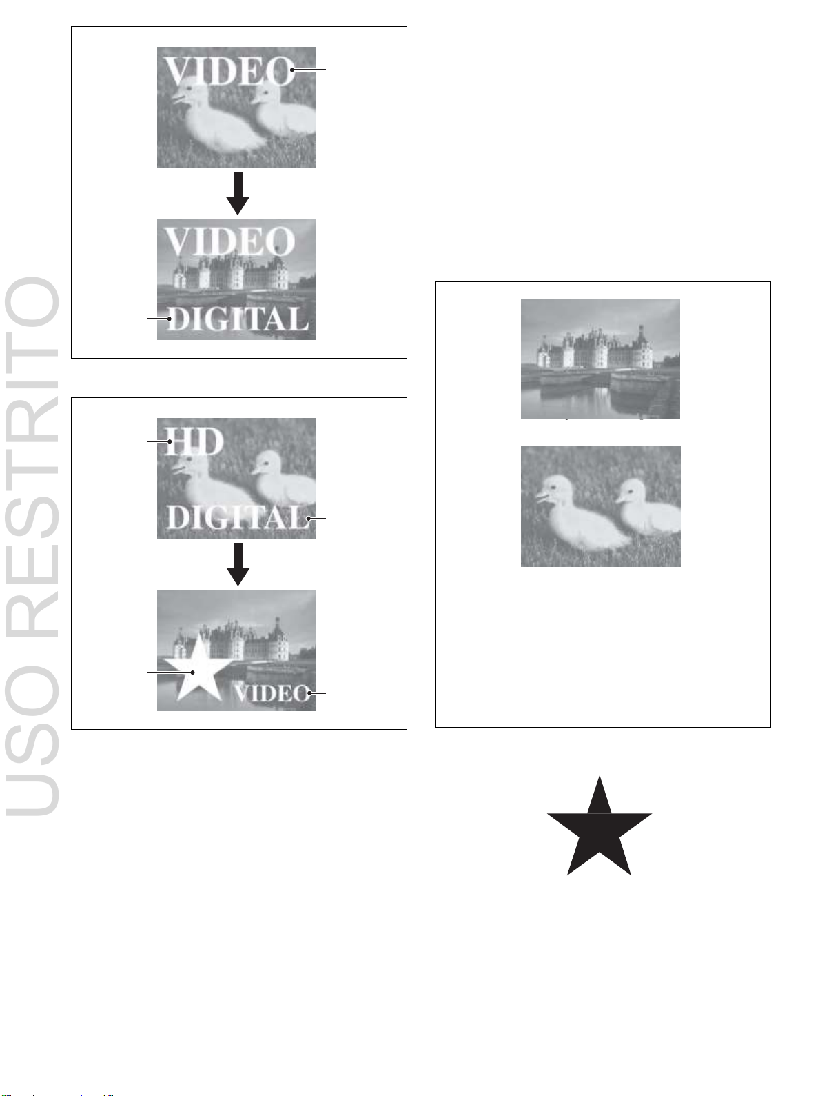
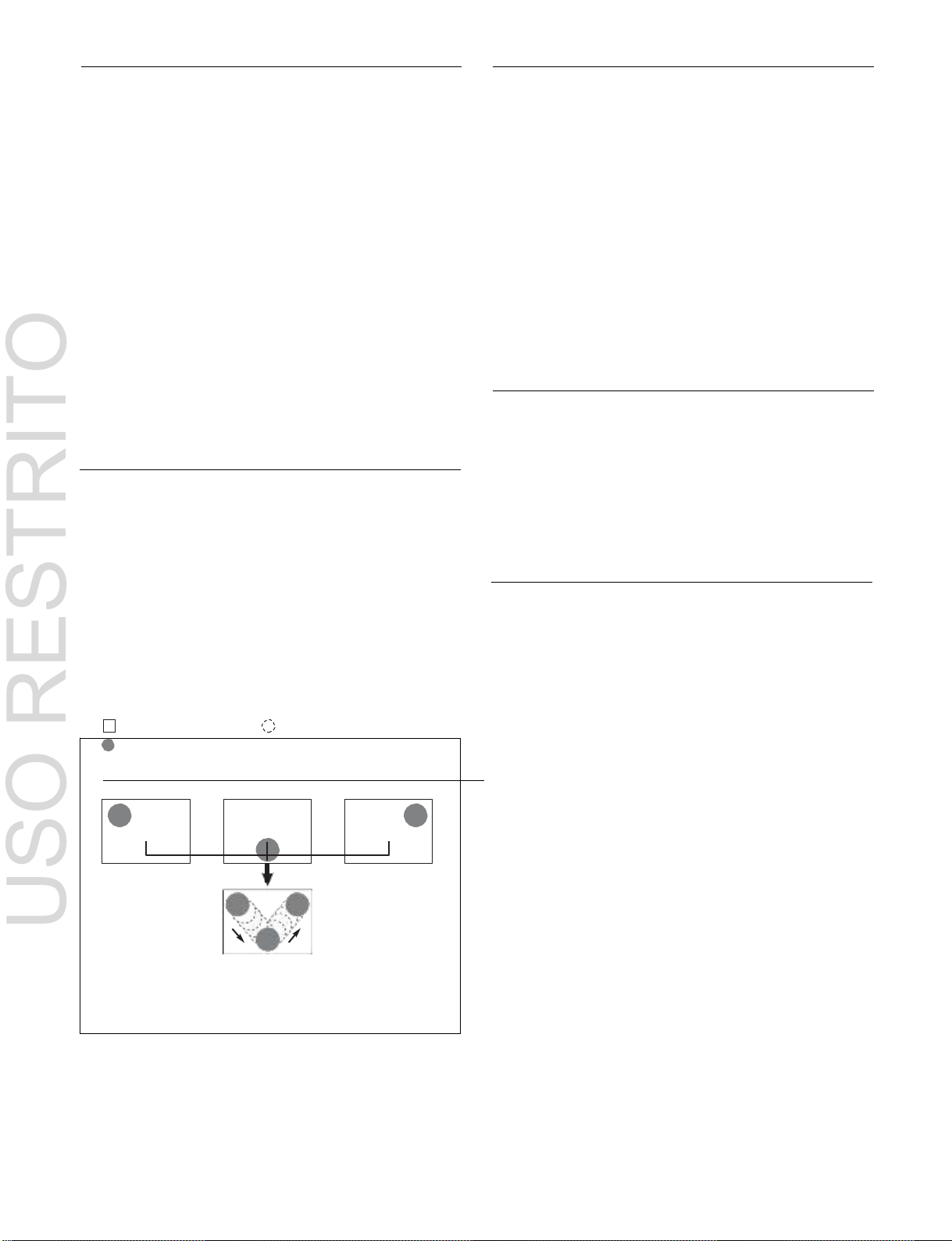
Inserting and deleting a key
Background A
Transition
Background B
Insert Delete
Key 1
Key 2
Key 1
Transition
Key 2
USO RESTRITO
Basic Video Processing
This section introduces basic functions used for video
processing on the switcher.
is also possible.
You can insert one or more of the eight keys (or
downstream keys 1 to 8 on the PGM/PST bank) into the
image.
If you select a key which is already inserted, the transition
will delete the key.
A simultaneous combination of deleting and inserting keys
Transition
In the M/E banks and PGM/PST bank, the switch from the
current video stream (appearing on the corresponding
program monitor) to a new video stream is referred to as a
transition.
In the M/E banks and PGM/PST bank, you can change one
image on the background or on keys 1 to 8 (downstream
keys 1 to 8 in the PGM/PST bank), and also vary the
combination of these simultaneously.
Note
When the signal format is 1080P, only keys 1 to 4 can be
used.
The following are examples of basic transitions.
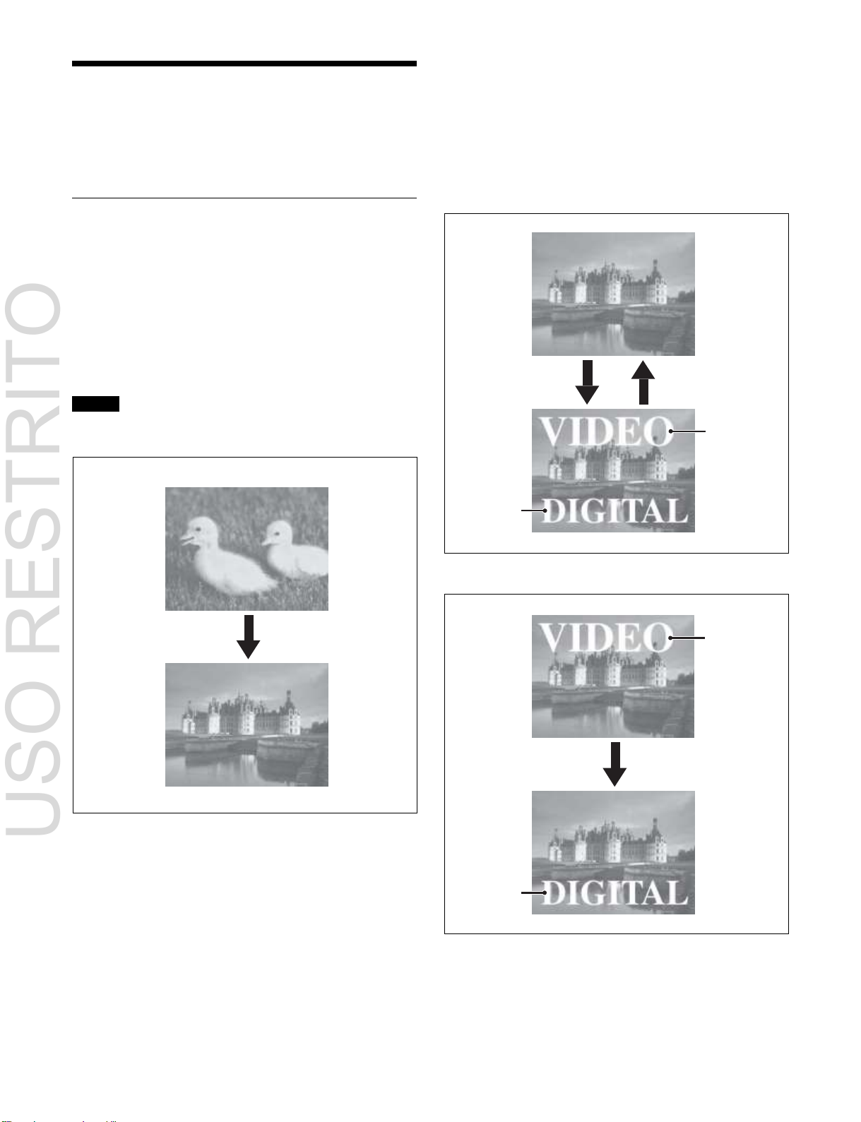
Changing the background
A background transition switches from the video currently
selected on the background A bus (the current video) to the
video selected on the background B bus (the new video).
In the default selection of flip-flop mode (see page 87), the
background always switches in the direction A bus t B
bus. When the transition completes, the cross-point
selections on the A and B buses are interchanged.
Inserting or deleting key 1 and key 2
Deleting key 1 and inserting key 2
19
Simultaneously changing the background
Background A
Background B
Key to insert
Key 1
Key 2
Transition
Key 3
Key 4
Key 1
Transition
Key 2
USO RESTRITO
and keys
You can change one or more of the eight keys
(downstream keys 1 to 8 on the PGM/PST bank) and the
background at the same time.
•
Wipe
•
DME Wipe
•
Clip transition
•
Cut
There are two modes for carrying out a transition: auto
transitions are carried out by a button operation, and
manual transitions are carried out using the fader lever. It
is also possible to combine these two modes.
Independent key transition
In addition to common transitions, it is possible to carry
out independent transitions on the keyers of the M/E banks
and PGM/PST bank.
By carrying out an independent key transition in
combination with a common transition, different transition
types can be used for the background and keys.
The following compares the independent key transition
with a common transition, taking a simultaneous change of
the background and key as an example.
Video used in the transition
Changing the background and keys 1 to 2 simultaneously
Changing the background and keys 1 to 4 simultaneously
Selecting the transition type determines the way in which
the transition occurs.
The following transition types are available.
•
Mix
•
NAM (non-additive mix)
•
Super mix
•
Preset color mix (color matte)
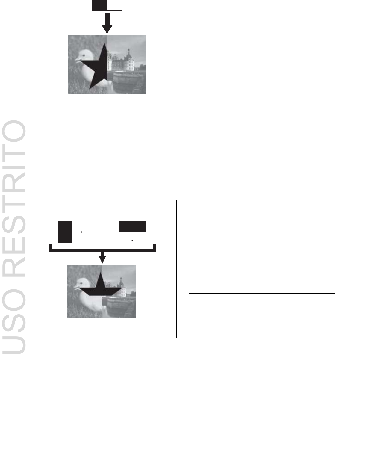
Effect of a common transition
In the case shown in the previous illustration, carrying out
a common transition produces the following change in the
image.
20
Transition type: wipe
Same wipe is applied to background and key.
Transition type: wipe
Independent key transition
type: wipe
Different wipe patterns are applied to the
background and key transitions.
USO RESTRITO
Effect of use with an independent key transition
The key is inserted with an independent key transition as
the background changes with a common transition,
providing the following result.
Each M/E bank and the PGM/PST bank has eight keyers,
and all of these keyers provide the same functions.
You can use the following key types (methods of
processing the key source).
•
Luminance key
•
Linear key
•
Color vector key
•
Chroma key
•
Wipe pattern key
•
Key wipe pattern key
Key modifiers
You can apply borders and other modifiers to the edge of
the key image.
Masks
A mask allows a part of the image to be replaced by the
background or a key. You can correct the image, such as
unwanted holes that appear in the background or when a
key is not the desired shape, using masks.
Resizer
This function allows you to apply effects, such as zoom,
movement, or aspect ratio change to a part of a created key.
The following functions are available.
•
Two-dimensional transform of keys
•
Rotation of keys
•
Resizer interpolation settings
•
Resizer crop/border settings
•
Resizer effect settings (wide key border, drop shadow,
edge enhancement, mosaic, defocus, mask)
For details, see “Keys” (page 95).
For details, see “Signal Selection and Transitions”
(page 67).
Keys
A key is an effect in which a part of the background image
is replaced by an image or superimposed text. The signal
determining how the background is cut out is termed the
“key source,” and the signal that replaces the cut-out part
is termed the “key fill.” The system component
responsible for processing a key is referred to as a “keyer.”
Wipes
A wipe is a transition from the current video stream to a
new video stream, using a wipe pattern.
Changing the background by means of a wipe is referred to
as a “background wipe,” and inserting or deleting a key
with a wipe is termed a “key wipe.”
There are two types of wipe: those that can be selected in
a common transition, and those that can be selected in an
independent key transition.
The patterns that can be used for a wipe are as follows.
•
Standard wipes
•
Enhanced wipes
•
Rotary wipes
•
Mosaic wipes
•
Random/diamond dust wipes
You can combine two selected patterns (referred to as
“main” and “sub”) to create a new pattern (pattern mix).

21
You can also specify the wipe direction, or set the pattern
USO RESTRITO
position, applying various changes and modifiers to the
selected wipe pattern.
For details, see “Wipes” (page 125).
DME Wipes
A DME wipe is a wipe transition that uses a DME effect to
change from one video image to the next.
There are two types of DME wipe: those which can be
selected for a normal transition, and those which can be
selected for an independent key transition.
The patterns that can be used for a DME wipe are as
follows.
Slide, Squeeze, Split, Door, Flip tumble, Mirror, Sphere,
Character trail, Wave, Ripple, Page turn, Roll, Frame inout, Picture-in-picture, 2D trans, 3D trans, Sparkle, Split
slide, Mosaic, Defocus, Brick, and User programmable
DME
You can also specify the wipe direction, or set the pattern
position, applying various changes and modifiers to the
selected DME wipe pattern.
Resizer DME wipes
Using the resizer, you can carry out key DME wipes.
For details, see “DME Wipes” (page 138).
Frame Memory
Copy and Swap
This function can be used to copy and swap the settings
between M/E banks and PGM/PST bank, and between
keyers.
The following settings can be copied or swapped.
•
Settings for the M/E banks and PGM/PST bank
•
Keyer settings
•
Wipe settings in a transition control block
•
Independent key wipe settings in a transition control
block
•
DME wipe settings in a transition control block
•
Independent key DME wipe settings in a transition
control block
•
Matte color settings (color 1, color 2, and how to
compose them)
•
Color settings
•
DME channel settings
•
Format converter input settings (copy only)
•
Format converter output settings (copy only)
For details, see “Copy and Swap” (page 177).
Video Process
The term “video process” is applied to adjustments to the
gain, hue, and black level of the input video signal. There
are two types of adjustment: adjustment for each input
signal and adjustment for each bus.
For details, see “Video Process” (page 184).
Frame memory is a function for using a still image or video
(frame memory clip) as material for editing.
You can create a still image by capturing a frame of input
video or a clip by specifying a range of input video. The
created images and clips can be written to memory for
playback, editing, and output.
For details, see “Frame Memory” (page 153).
Color Backgrounds
This function can be used to obtain color background
video.
Two color signals generated from the dedicated generators
can be switched or mixed, and then output.
For details, see “Color Backgrounds” (page 176).
Color Corrector
The color corrector enables video signal color correction
(black balance/white balance adjustment, gamma
correction, knee correction, etc.).
The color corrector includes the following adjustments.
•
Input video processing
•
Primary color correction
•
Secondary color correction
•
Luminance processing
•
Spot colors
•
Output video processing
•
YUV/RGB clips
For details, see “Color Corrector” (page 186).
Side Flags
The term “side flags” refers to the areas to the left and right
of an image with aspect ratio 4:3 embedded within a 16:9
22
Enable side flags
Side flag area
Side flag area
frame, with these areas filled with a separate image
Background B
Background A
Key (key 1 to key 8 are available
on the main side.)
Image to fill the side flag
areas (signal selected
from utility 1 bus)
Input source with
aspect ratio 4:3
Background B
(signal from utility 3 bus)
Background A
(signal from utility 2 bus)
Key (key 2 to key 8 are available on
the sub side.)
USO RESTRITO
selected from the utility 1 bus.
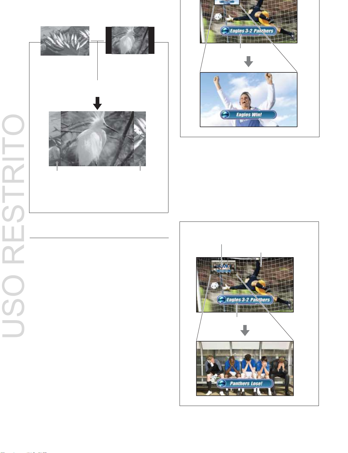
Program output for “Main”
For details, see “Side Flags” (page 194).
Multi Program 2
This function divides a single M/E switcher bank into two
(“main” and “sub”). You can this function to create images
separately on each. For example, during broadcast of
sports events, two versions of the scene can be provided as
shown below, and switched simultaneously.
Program output for “Sub”
For details, see “Multi Program 2” (page 197).

23
USO RESTRITO
4K Support
4K image processing is supported by installing 4K upgrade
software and switcher upgrade software.
For details about the switcher configuration required for
4K support, contact your Sony service or sales
representative.
For details, see “4K System” (page 204).
Creation of Special
Effects and Management
of Data and Operations
This section introduces functions used for creation of
special effects, control of external devices or switcher
operations, and data management.
Digital Multi Effects (DME)
When used with the switcher, DME allows you to add
three-dimensional effects such as image movement,
rotation, magnification and shrinking, as well as a wide
variety of special effects.
Each channel can be used on its own or in combination
with other channels, which allows you to create advanced
effects with more complexity.
The following types of DME special effects are available.
•
Edge effects: Border, CG Border, Crop, Beveled Edge,
Key Border, Art Edge, Flex Shadow, Wipe Crop
•
Effects for entire image: Defocus, Blur, Multi Move
•
Video image effects: Sepia, Mono, Posterization,
Solarization, Nega, Contrast, Mosaic, Mask, Sketch,
Metal, Dim and Fade, Glow
•
Freeze effects
•
Nonlinear effects: Wave, Mosaic Glass, Flag, Twist,
Ripple, Rings, Broken Glass, Flying Bar, Blind, Split,
Split Slide, Mirror, Multi Mirror, Kaleidoscope, Lens,
Circle, Panorama, Page Turn, Roll, Cylinder, Sphere,
Explosion, Swirl, Melt, Character Trail
•
Corner pinning effect
•
Lighting effects: Lighting, Spotlighting
•
Recursive effects: Trail, Motion Decay, Keyframe
Strobe, Wind
•
Background color settings
•
Separate Sides (effects for front and back sides)
•
Signal inversion (Invert effect)
•
Key density adjustment
•
Key source selection
•
Color mix settings
Global effects
Global effects are special effects created by combining the
images of successive channels.
The following types of global effects are available.
•
Combiner
•
Brick
•
Shadow
For details, see “DMEs” (page 209).
24
Background A
Background B
Image created by interpolation
Keyframe 1
Keyframe 2
Keyframe 3
Effect execution
USO RESTRITO
External Device Control
Snapshots
You can operate this system while controlling the
following types of external device.
•
P-Bus (Peripheral II protocol) devices
•
GPI devices
•
VTRs
•
Disk recorders (video disk communications protocol,
Odetics protocol)
•
Extended VTRs (Abekas A53 protocol)
For details about the devices that can be connected,
consult your Sony representative.
You can also control an external device by registering
timeline keyframes beforehand.
For details, see “External Devices” (page 283).
The term “snapshot” refers to a function whereby the
various settings required to apply a particular effect to an
image are saved in a register as a set of data, for recall as
required, to recover the original state.
Snapshots are classified as follows.
•
Snapshots applying to a particular region (functional
block of the switcher or DME)
•
Master snapshots
•
Key snapshots
•
Wipe snapshots
•
DME wipe snapshots
For details, see “Snapshots” (page 330).
Utility
The utility function allows you to assign an arbitrary action
or a shortcut for frequently used menu to a particular
Keyframes
button, to instantly recall the action or menu by pressing
the button.
A keyframe represents an instantaneous state of an image,
which can be saved in a register and recalled for reuse. By
For details, see “Utility Overview” (page 340).
arranging a number of keyframes on the time axis, and
interpolating between successive keyframes, you can
create a “keyframe effect” in which there is a continuous
Shotbox
change from each keyframe to the next.
The following figure shows three keyframes created with
a wipe pattern (the circle) in different positions,
interpolated to create the effect shown.
The shotbox function allows you to recall any snapshot or
keyframe effect for specified regions (see page 297)
simultaneously.
For details, see “Shotbox Overview” (page 342).
Macros
Example of keyframes and effect execution
You can save the sequence of keyframes representing a
single effect in a register. Then by recalling this register,
you can replay the same effect.
For details, see “Keyframes” (page 297).
The macro function allows you to store a sequence of
signal selections and other operations on the control panel
as data in memory (macro register), and then recall the
data, when required, to automatically execute the same
sequence of operations.
The individual control panel operations constituting a
macro are termed “events.”
Macros also provide the following functions.
Menu macros
The menu macro function allows you to register menu
operations as events, which can be recalled, when
required, to automatically execute the same menu
operations.
Macro timeline
You can automatically execute a sequence of macro recall/
execute actions by registering them on a timeline, in the
same way as for keyframes in an effect.

25
Macro attachment
USO RESTRITO
The macro attachment function allows you to assign a
control panel button or a particular position of a fader lever
to a macro register, linking the execution of the button
function or a fader lever operation with a macro execution.
For details, see “Macros” (page 348).
File Operations
You can save register data, including setup information
and snapshot information, as a file on a local drive or
removable drive, and recall it as required.
Images in frame memory can be imported from an external
device, converted to a different format, and then saved.
For details, see “Files” (page 375).
Setup
Various settings are required, in order to operate the
switcher, control panel, DME, external devices, and so on,
connected together in a single system.
This is referred to as “setup.” You perform the setup
operations from the Engineering Setup menu (hereinafter
called the Setup menu).
The settings in the Setup menu are grouped under the
following headings.
System setup (System)
For details, see “System Setup” (page 389).
Panel setup (Panel)
For details, see “Control Panel Setup” (page 408).
Switcher setup (Switcher)
For details, see “Switcher Setup” (page 434).
DME setup (DME)
For details, see “DME Setup” (page 457).
DCU setup (DCU)
For details, see “DCU Setup” (page 461).
Router/tally setup (Router/Tally)
For details, see “Router Interface and Tally Setup”
(page 470).
User setup (User Setup)
For details, see “User Setup” (page 477).
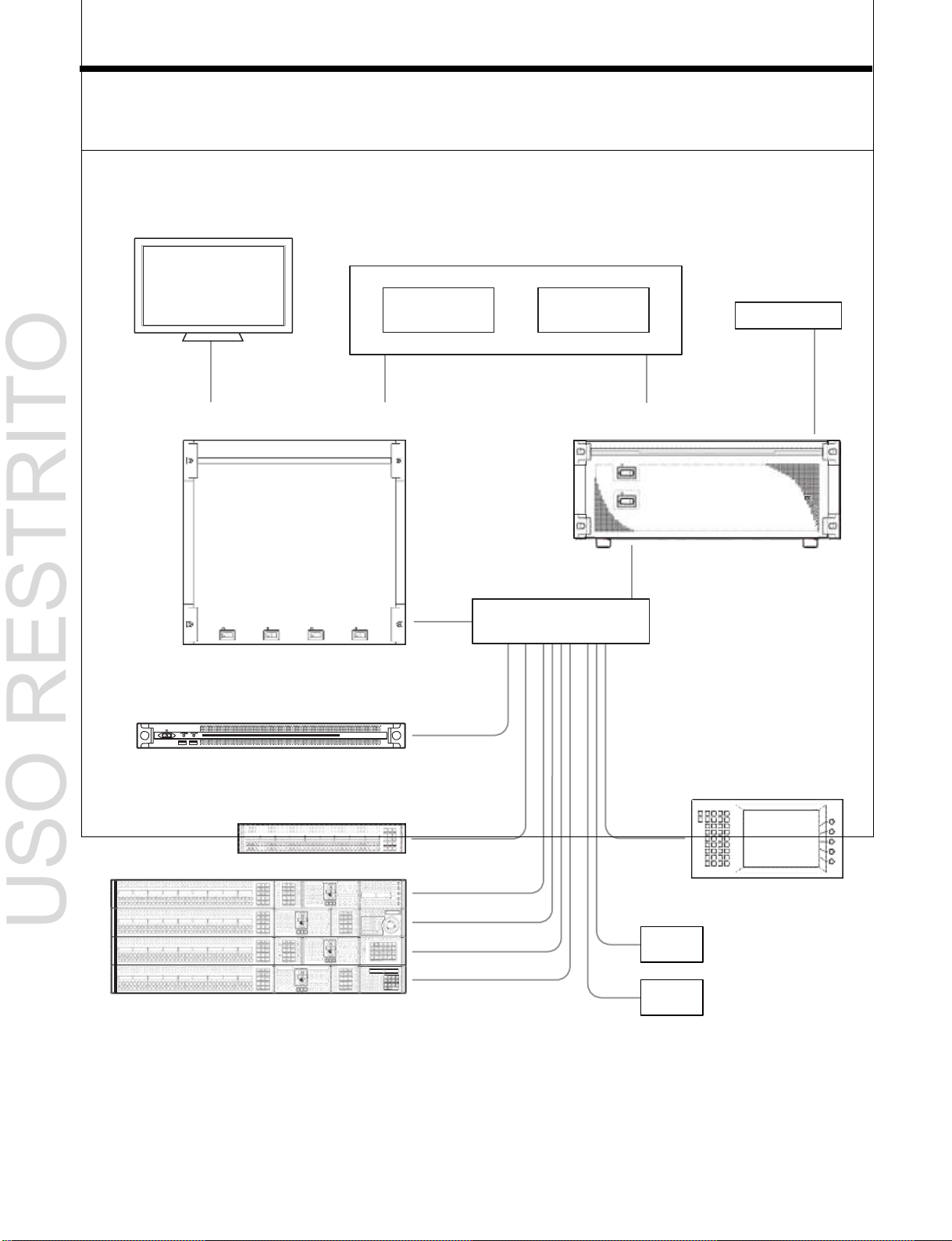
26
VTR DDR
BKS-R series
MVS-8000X/7000X
Multi Format Switcher Processor
MKS-X7700
System Interface Unit
POWER A
POWER B
PoE
Ethernet switch
PWS-100SC1
Switcher Control Station
MKS-X7011
Menu Panel
MKS-X7075
Extension Adaptor
ICP-X7000
Integrated Control Panel
Monitor
USO RESTRITO
System Configuration
System Configuration Example
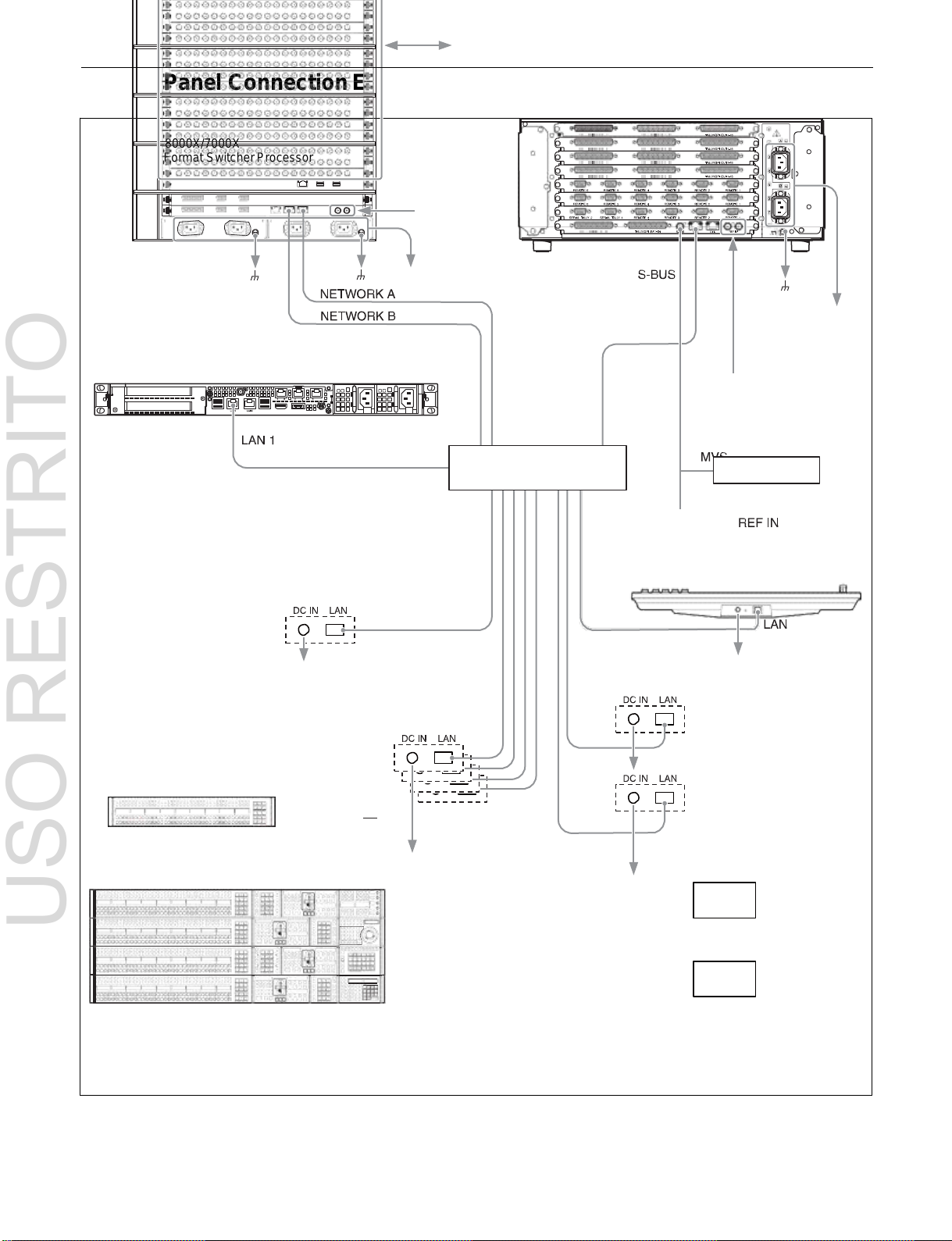
27
Connection with video device via SDI interface
MKS-X7700
System Interface Unit
Reference
video signal
To AC supply
To AC supply
PWS-100SC1
Switcher Control Station
Reference video signal
PoE
Ethernet switch
BKS-R series
MKS-X7011
Menu Panel
To AC adaptor
To AC adaptor
MKS-X7075
Extension Adaptor
Per row
ICP-X7000
Integrated Control Panel
MKS-X7075
Extension Adaptor
To AC adaptor
USO RESTRITO
Control Panel Connection Example
MVS-8000X/7000X
Multi Format Switcher Processor
To AC adaptor

28
Control block
Module
Cross-point control block
MKS-X7017, MKS-X7018,
MKS-X7019
a) b)
AUX bus control block
Transition control block
MKS-X7020
Flexi Pad control block
MKS-X7024
Key control block
MKS-X7035
Numeric keypad control
block
MKS-X7026
Device control block
(trackball)
MKS-X7031TB
Utility/shotbox control block
MKS-X7033
Menu panel
MKS-X7011
Menus and Control Panel
Chapter
2
USO RESTRITO
Names and Functions of Parts of the Control Panel
The maximum number of M/E banks supported by the
MVS-8000X/7000X system is given below.
MVS-8000X
Five M/E banks maximum (PGM/PST, M/E-1 to M/E-4)
MVS-7000X
Six M/E banks maximum (PGM/PST, M/E-1 to M/E-5)
Note
On the MVS-8000X, M/E-5 cannot be used. M/E-5
operation and settings are disabled, even if they appear in
the menu.
For details, see “Disabled Menus on the MVS-8000X”
(page 510).
Control Panel Configuration
The ICP-X7000 integrated control panel provides flexible
support for a combination of several modules.
The name of each control block and the supported modules
are given below.
a) The cross-point control block and AUX bus control block use the same
module. If installed in the same row as the transition control block, it
becomes the cross-point control block. If not installed in the same row as
the transition control block, it becomes the AUX bus control block.
b) There are three types of modules with varying numbers of cross-point
buttons: 36 buttons (MKS-X7017), 28 buttons (MKS-X7018), and 20
buttons (MKS-X7019).
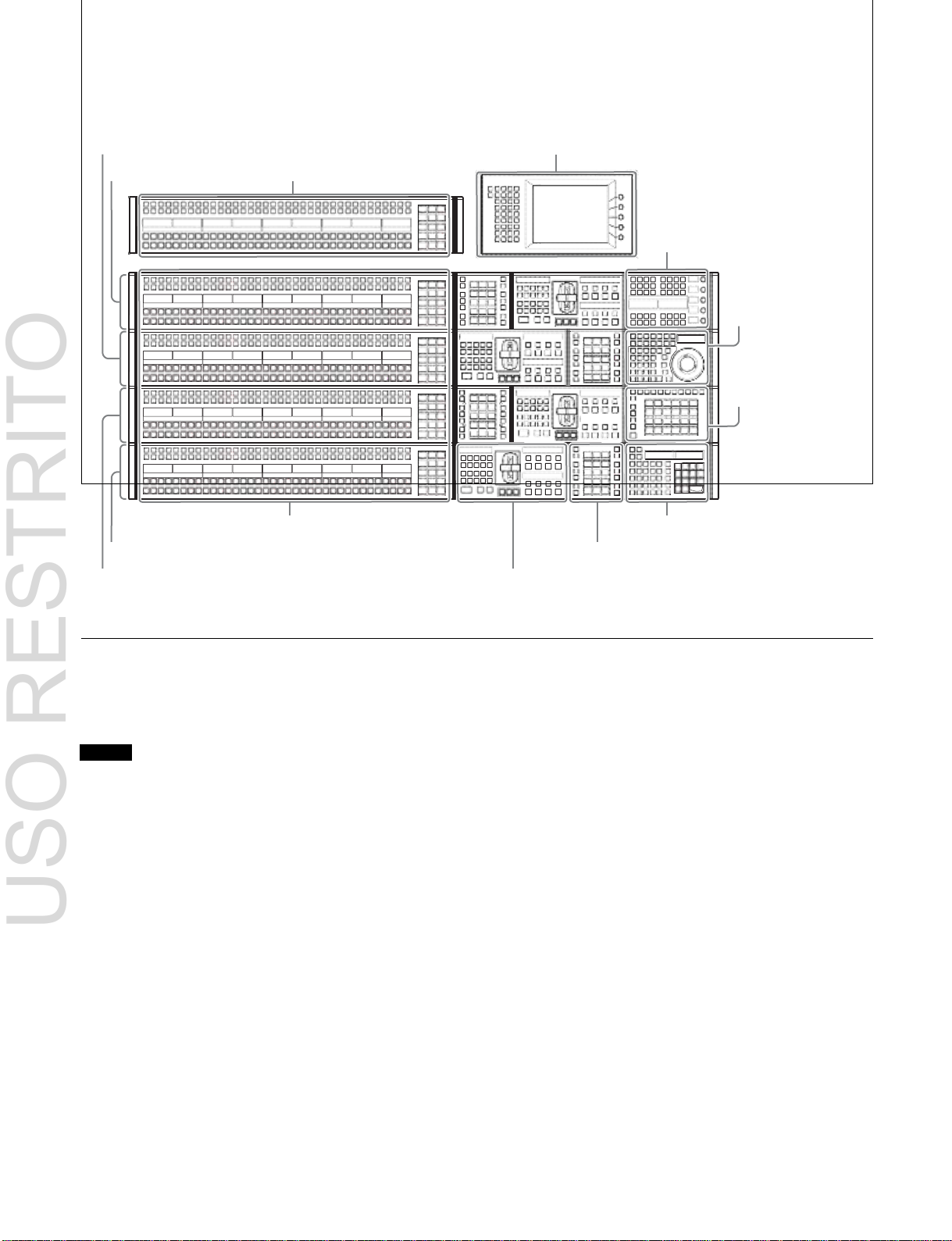
29
AUX bus control block
M/E-1 bank
(page 46)
Key control block (page 37)
Device control block
(page 40)
Utility/shotbox control
block (page 45)
Cross-point control block (page 29)
Numeric keypad control block (page 43)
PGM/PST (program/preset) bank
Flexi Pad control block (page 36)
4M/E configuration example using 36-button modules for cross-point control block and AUX bus
M/E-2 bank
Menu panel (page 49)
M/E-3 bank
Transition control block (page 33)
USO RESTRITO
control block
Cross-Point Control Block
The cross-point control block is used to select the signals
to be used in the M/E banks and PGM/PST bank.
Note
In the case of the MVS-8000X, only the premium inputs
(inputs to the switcher premium input connectors 1 to 20)
can be selected as key signals on M/E-4.
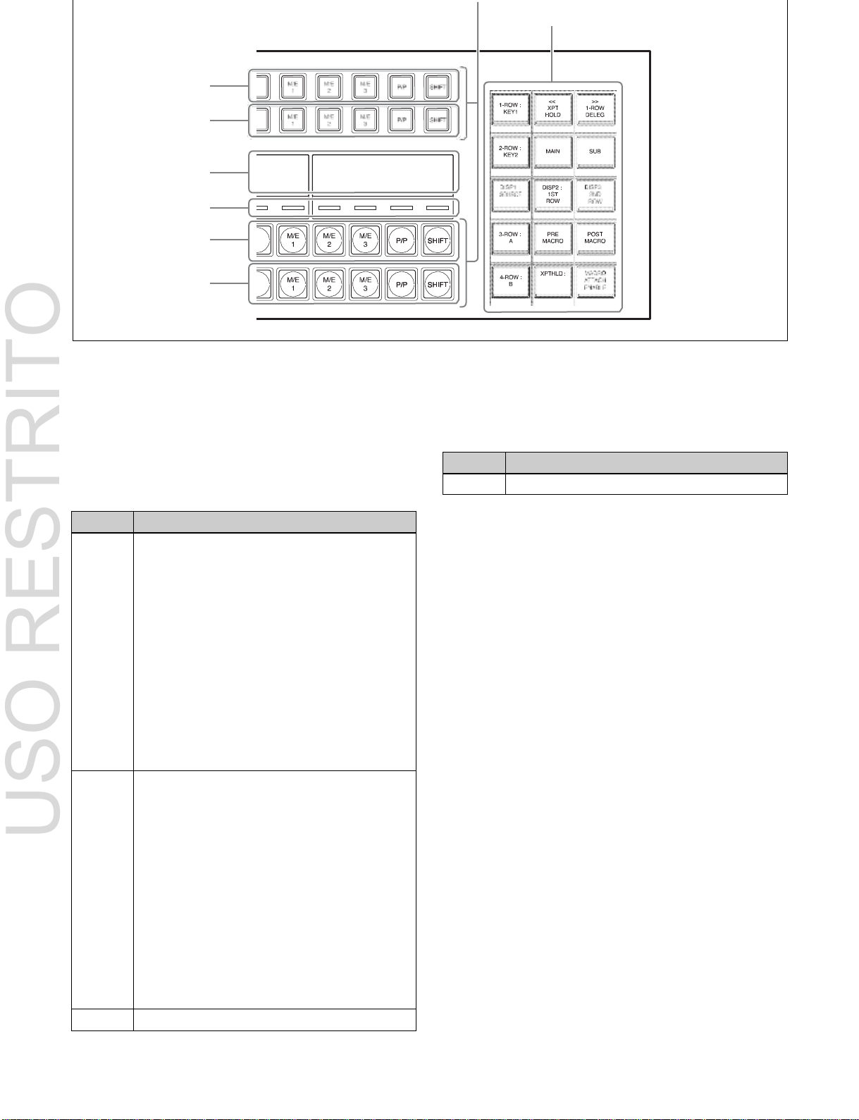
30
Name
Description
4th row
Selects background B bus signal.
a
Button rows
d
Cross-point Flexi Pad
1st row
2nd row
b
Display
c
Cross-point
indicators
3rd row
4th row
Name
Description
1st row
• Selects the following bus signals selected
using the cross-point Flexi Pad delegation
buttons.
Key busa), utility bus, DME external video bus,
DME utility bus
• Selects the following functions when utility/
shotbox bank is selected using the cross-point
Flexi Pad delegation buttons (utility/shotbox
mode).
b)
Utility command, menu shortcut, macro recall,
shotbox recall
• Selects the shifted signal on the background A
bus when the [DUAL BKGD BUS] button of the
cross-point Flexi Pad is lit (dual background
bus mode).
2nd row
• Selects the following bus signals selected
using the cross-point Flexi Pad delegation
buttons.
Key busa), utility bus, DME external video bus,
DME utility bus
• Selects the following functions when utility/
shotbox bank is selected using the cross-point
Flexi Pad delegation buttons (utility/shotbox
mode).
b)
Utility command, menu shortcut, macro recall,
shotbox recall
• Selects the shifted signal on the background B
bus when the [DUAL BKGD BUS] button of the
cross-point Flexi Pad is lit (dual background
bus mode).
3rd row
Selects background A bus signal.
USO RESTRITO
a
Button rows
Used as cross-point buttons for selecting signals and
functions.
a) When a cross-point button is pressed, a key fill signal is selected. When a
cross-point button is pressed while pressing a delegation button, a key
source signal is selected.
b) Utility/shotbox mode functions are assigned in the Setup menu. The
settings are common to the M/E and PGM/PST banks.
For details, see “Assigning Functions to 1st Row/2nd Row Buttons of the
Cross-Point Control Block” (page 425).
Cross-point button numbers
The button numbers are labeled on the cross-point buttons.
For details, see “Cross-point control block button
numbers” (page 72).
Assigning signals to button numbers
You can assign a signal to each button number in the Setup
menu.
For details, see “Creating Cross-Point Assign Tables”
(page 413).
Colors of lit cross-point buttons
The status of cross-point buttons can be checked according
to the color of the button when lit.
For details, see “Colors of lit cross-point buttons”
(page 74).
Re-entry buttons
Re-entry buttons are assigned to the cross-point button
rows (M/E-4 and M/E-5 re-entry buttons must be assigned
in the Setup menu). Re-entry buttons can also be assigned
to the cross-point Flexi Pad.
 Loading...