

Sony ICP-6530, ICP-6511, ICP-6520, ICP-3000 Installation Manual

2M/E CONTROL PANEL
ICP-6520
ICP-3000
3M/E CONTROL PANEL
ICP-6530
MENU PANEL
ICP-6511
INSTALLATION MANUAL
1st Edition

!警告
このマニュアルは,サービス専用です。
お客様が,このマニュアルに記載された設置や保守,点検,修理などを行うと感電や火災,
人身事故につながることがあります。
危険をさけるため,サービストレーニングを受けた技術者のみご使用ください。
! WARNING
This manual is intended for qualifi ed service personnel only.
To reduce the risk of electric shock, fi re or injury, do not perform any servicing other than that
contained in the operating instructions unless you are qualifi ed to do so. Refer all servicing to
qualifi ed service personnel.
! WARNUNG
Die Anleitung ist nur für qualifi ziertes Fachpersonal bestimmt.
Alle Wartungsarbeiten dürfen nur von qualifi ziertem Fachpersonal ausgeführt werden. Um die
Gefahr eines elektrischen Schlages, Feuergefahr und Verletzungen zu vermeiden, sind bei
Wartungsarbeiten strikt die Angaben in der Anleitung zu befolgen. Andere als die angegeben
Wartungsarbeiten dürfen nur von Personen ausgeführt werden, die eine spezielle Befähigung
dazu besitzen.
! AVERTISSEMENT
Ce manual est destiné uniquement aux personnes compétentes en charge de l’entretien. Afi n
de réduire les risques de décharge électrique, d’incendie ou de blessure n’effectuer que les
réparations indiquées dans le mode d’emploi à moins d’être qualifi é pour en effectuer d’autres.
Pour toute réparation faire appel à une personne compétente uniquement.
警告
本機は1次側電源を遮断するスイッチを備えていません。
万一,異常が起きた際に,お客様が電源を切ることが
できるように,設置の際には,機器近くの固定配線内
に専用遮断装置を設けるか,機器使用中に,容易に抜
き差しできるコンセントに電源プラグを接続してくだ
さい。
WARNING
This unit has no switch to cut off the primary power supply.
When installing the unit, incorporate a readily accessible
disconnect device in the fi xed wiring, or connect the
power cord to a socket-outlet which must be provided
near the unit and easily accessible, so that the user can
turn off the power in case a fault should occur.
WARNUNG
Dieses Gerät hat keinen Netzschalter zum Unterbrechen
der primären Stromversorgung.
Beim Einbau des Geräts ist daher im Festkabel
ein leicht zugänglicher Unterbrecher einzufügen,
oder das Netzkabel muß mit einer in der Nähe
des Geräts befi ndlichen, leicht zugänglichen
Wandsteckdose verbunden werden, damit sich bei
einer Funktionsstörung die Stromversorgung zum Gerät
jederzeit unterbrechen läßt.
安全のために,周辺機器を接続する際は,過大電圧を持
つ可能性があるコネクターを以下のポートに接続しない
でください。
: MVS コネクター
: UTIL コネクター
上記のポートについては本書の指示に従ってください。
For safety, do not connect the connector for peripheral device wiring that might have excessive voltage to the following ports.
: MVS connector
: UTIL connector
Follow the instructions for the above ports.
For kundene i Norge
Dette utstyret kan kobles til et IT-strømfordelingssystem.
ICP-6520/6530/3000/6511

設置時には,通気やサービス性を考慮して設置スペー
スを確保してください。
. ファンの排気部や通気孔(左側面および右側面)をふ
さがない。
. 通気のために,セット周辺に空間をあける。
. 作業エリアを確保するため,セット後方は,10cm 以
上の空間をあける。
机上などの平面に設置する場合は,左側面および右側
面は 10cm 以上の空間をそれぞれ確保してください。
ただし,セット上部はサービス性を考慮し 10cm 以上
の空間を確保することを推奨します。
When installing the installation space must be secured
in consideration of the ventilation and service operation.
Do not block the ventilation slots at the left side and
.
right side panels, and vents of the fans.
Leave a space around the unit for ventilation.
.
Leave more than 10 cm of space in the rear of the unit
.
to secure the operation area.
When the unit is installed on the desk or the like, leave
at least 10 cm of space in the left and right sides.
Leaving 10 cm or more of space above the unit is
recommended for service operation.
ICP-6520/6530/3000/6511
1 (P)


Table of Contents
Manual Structure
Purpose of this manual ............................................................ 2 (E)
Related manuals ...................................................................... 2 (E)
Trademarks .............................................................................. 2 (E)
1. Installation
1-1. Operating Environment ............................................. 1-1 (E)
1-2. Power Supply ............................................................1-1 (E)
1-3. Installation Space ......................................................1-2 (E)
1-3-1. External Dimensions ........................................1-2 (E)
1-3-2. Installation Space ............................................1-5 (E)
1-4. Installing the ICP-6520/6530/3000 .......................... 1-7 (E)
1-5. Installing Menu Panel..............................................1-10 (E)
1-6. Setting the Switch Button Serigraph Labels ...........1-11 (E)
1-7. Matching Connectors and Cables ............................1-17 (E)
1-8. Input/Output Signals of Connectors ........................1-18 (E)
1-8-1. ICP-6520/6530/3000 ......................................1-18 (E)
1-8-2. ICP-6511 ........................................................ 1-19 (E)
1-9. Description of On-board Switches and LEDs ......... 1-20 (E)
1-9-1. ICP-6520/6530/3000 ......................................1-20 (E)
1-9-2. ICP-6511 ........................................................ 1-30 (E)
1-10. System Connection ..................................................1-32 (E)
1-10-1. Connection Example of the
ICP-6520/6530/6511 System .........................1-32 (E)
1-10-2. Connection Example of the
ICP-3000 System ........................................... 1-33 (E)
1-11. Removing the Module ............................................. 1-34 (E)
2. Service Overview
2-1. Troubleshooting.........................................................2-1 (E)
2-1-1. ICP-6520/6530/3000 ........................................2-1 (E)
2-1-2. ICP-6511 .......................................................... 2-1 (E)
2-2. Periodic Inspection and Maintenance .......................2-2 (E)
2-2-1. Periodic Inspection ..........................................2-2 (E)
2-2-2. Cleaning ...........................................................2-2 (E)
2-3. Recovery Mode ......................................................... 2-3 (E)
ICP-6520/6530/3000/6511
1 (E)

Purpose of this manual
Related manuals
Manual Structure
This manual is the Installation Manual of following models.
. 2M/E Control Panel ICP-6520/3000
. 3M/E Control Panel ICP-6530
. Menu Panel ICP-6511
This manual is intended for use by trained system and service engineers,
and provides the information that is required to install (operating environment,
installation space, connection information, etc.).
Besides this Installation Manual, the following manuals are prepared for this unit.
. Operation Manual (Supplied with this unit.)
This manual describes the outline and specifi cation of this unit.
. Maintenance Manual (Available on request)
This manual describes the maintenance and service information (service overview,
detailed parts list, block diagrams, board layouts, schematic diagrams, etc.) for this
unit.
Trademarks
Trademark and registered trademark used in this manual is follows.
. Ethernet is a registered trademark of Xerox Corporation.
Other system names, product names, and company names appearing in this manual
are trademarks or registered trademarks of their respective holders.
2 (E)
ICP-6520/6530/3000/6511
Section 1
Installation
1-1. Operating Environment
Operating guaranteed temperature: +5 dC to +40 dC
Performance guaranteed temperature: +10 dC to +35 dC
Operating humidity: 10 % to 90 %
Storage temperature: _20 dC to +60 dC
Mass
ICP-6520: Approx. 14.5 kg
ICP-6530: Approx. 20 kg
ICP-3000: Approx. 15 kg
ICP-6511: Approx. 2.3 kg
Prohibited locations for installation
. Areas where the unit will be exposed do direct sunlight
or any other strong lights.
. Dusty areas
. Areas subject to vibration.
. Areas with strong electric or magnetic fields.
. Areas near heat sources.
. Areas where is subject to electrical noise.
. Areas subject to static electricity.
Ventilation
The inside of the ICP-6520/6530/3000 is cooled by a fan.
The power supply can be damaged if the exhaust vent (side
on the right) and air intake (side on the left) are blocked or
the fan is stopped. (Refer to the air flow illustration of
“Fan” in Section 2-2-2.) Ensure a distance of 10 cm or
more from the air intake and exhaust vent.
1-2. Power Supply
Maximum inrush current
ICP-6520: 44 A peak, 10 A r.m.s. (240 V AC)
ICP-6530: 46 A peak, 11 A r.m.s. (240 V AC)
ICP-3000: 40 A peak, 10 A r.m.s. (240 V AC)
ICP-6511: 57 A peak, 8 A r.m.s. (240 V AC)
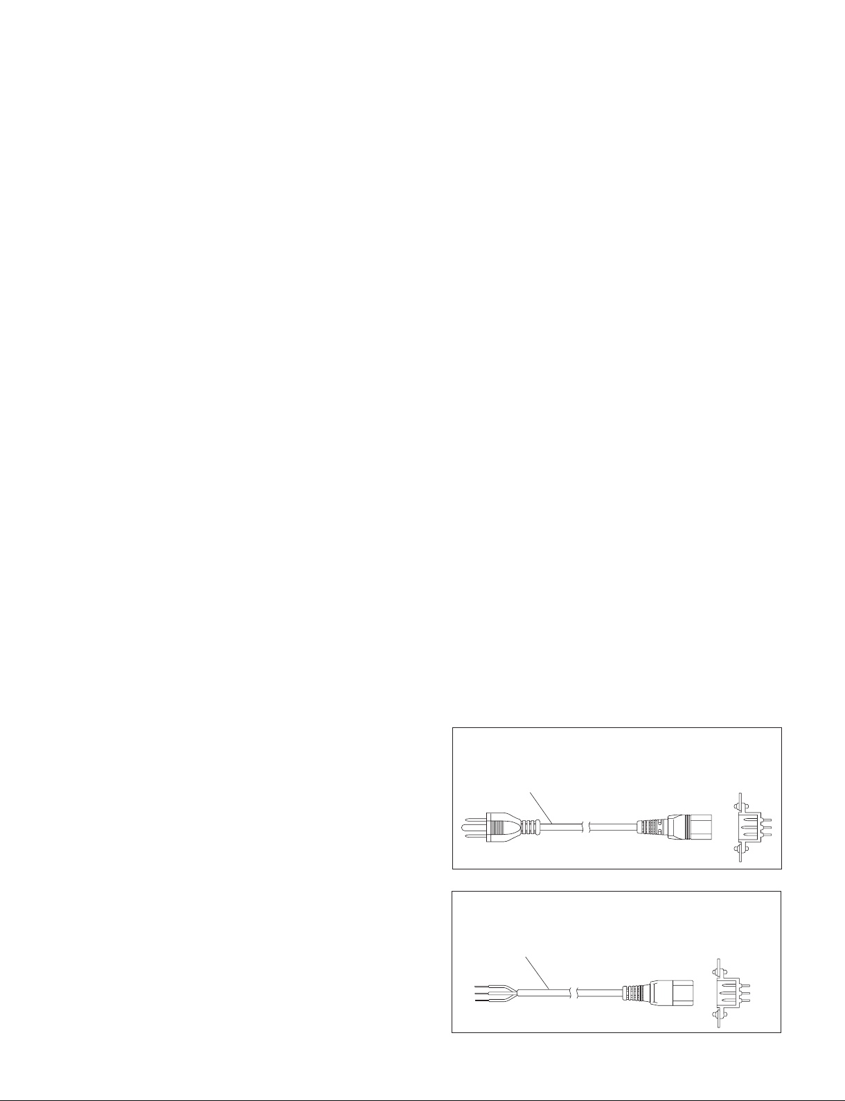
2. Power cord
This unit does not come with a power cord.
To get a power cord, please contact your local Sony Sales
Office/Service Center.
w
. Use the approved Power Cord (3-core mains lead)/Appli-
ance Connector/Plug with earthing-contacts that conforms to the safety regulations of each country if applicable.
. Use the Power Cord (3-core mains lead)/Appliance
Connector/Plug conforming to the proper ratings (Voltage, Ampere).
If you have questions on the use of the above Power Cord/
Appliance Connector/Plug, please contact your local Sony
Sales Office/Service Center.
w
. Never use an injured power cord.
. Plugging the power cord in the AC inlet, push as far as it
will go.
Specified power cord
For ICP-6520/6530/3000
1. Power specifications
A switching regulator is used for the power supply of
ICP-6520/6530/3000. A voltage within the range of 100 V
to 240 V can be used without changing the supply voltage.
Power requirements: AC 100 to 240 V, 10 %
Power frequency: 50/60 Hz
Current consumption: ICP-6520/6530/3000: Maximum 1.1A
n
As the inrush current flows at turn-on, the capacity of the
AC power source must be commensurate with this load.
If the capacity of the AC power is not adequately large, the
AC power source breaker will operate or the unit will
abnormally operate.
ICP-6520/6530/3000/6511
For customers in the U.S.A. and Canada
1 Power cord, 125 V 0 A (2.4 m) : ! 1-551-812-31
1
For customers in the all European countries
1 Power cord, 250 V 10 A (2.5 m) : ! 1-782-929-12
1
AC inlet
AC inlet
1-1 (E)
For ICP-6511
For customers in the U.S.A. and Canada
Power cord, 125 V 7 A (2.0 m) : ! 1-757-562-11
For customers in the U.S.A. and Canada
1 Power cord, 125 V 0 A (2.4 m) : ! 1-575-131-82
AC Adaptor
1
1-3. Installation Space
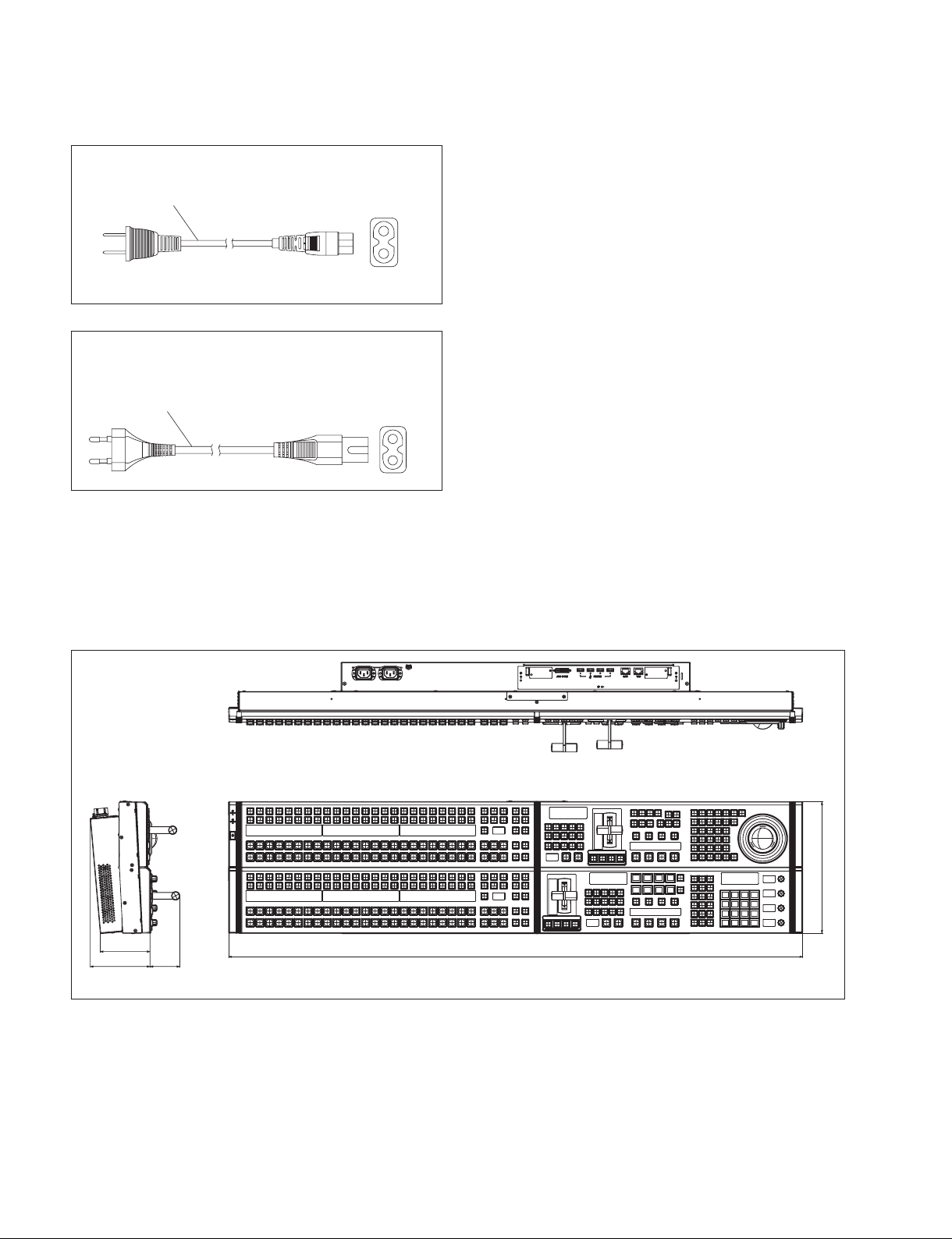
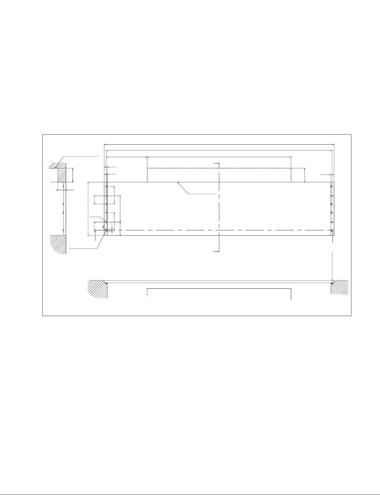
1-3-1. External Dimensions
ICP-6520
AC Adapter
1-2 (E)
100
120 60
264
115 4
Unit: mm
ICP-6520/6530/3000/6511
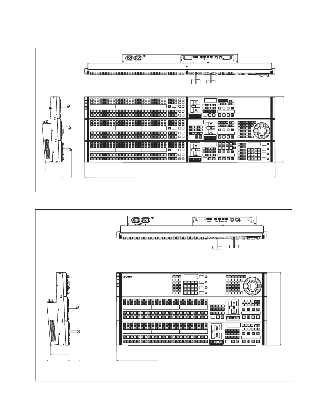
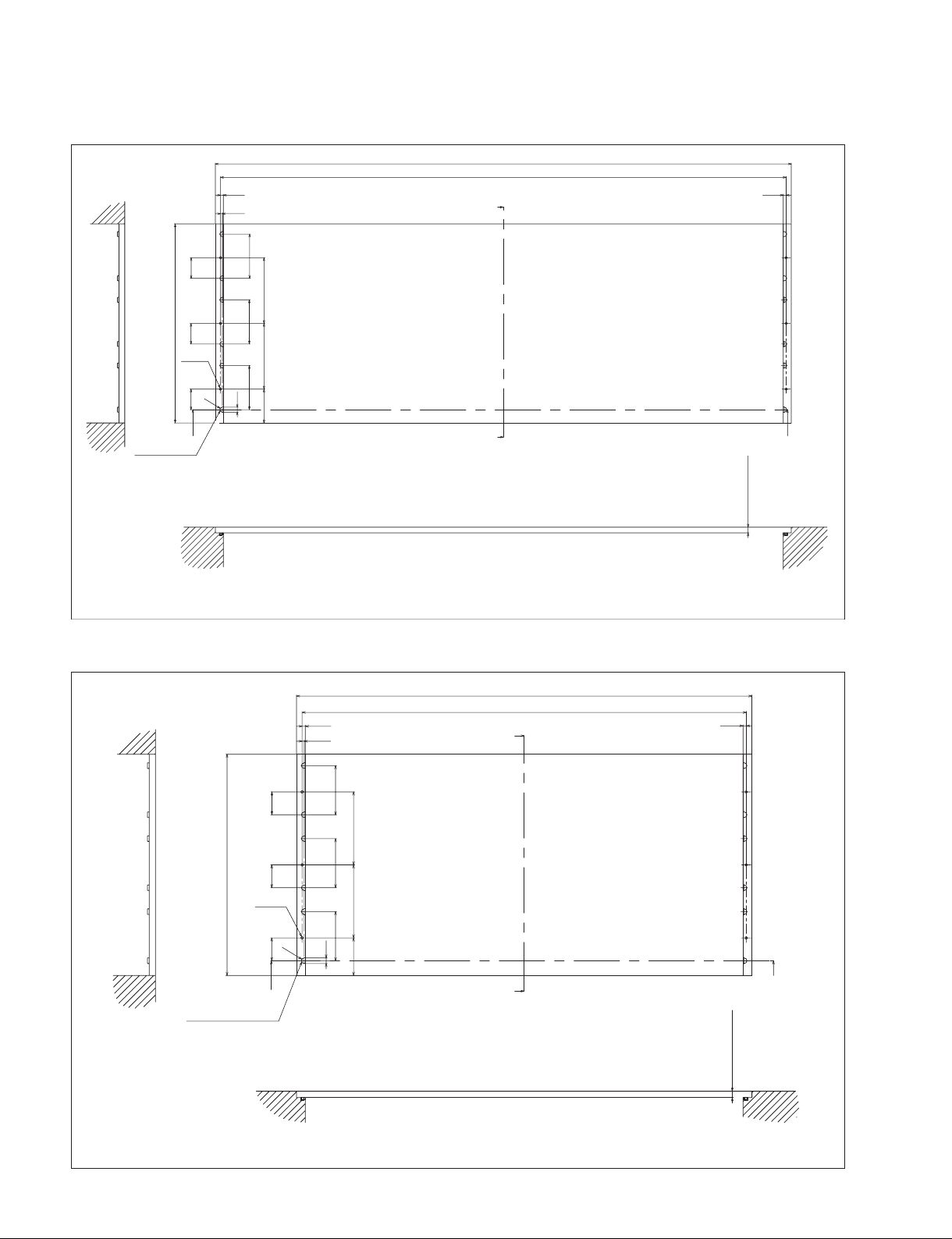
ICP-6530
100
120 60
396
115 4
Unit: mm
ICP-3000
100
120 60
396
821
ICP-6520/6530/3000/6511
Unit: mm
1-3 (E)
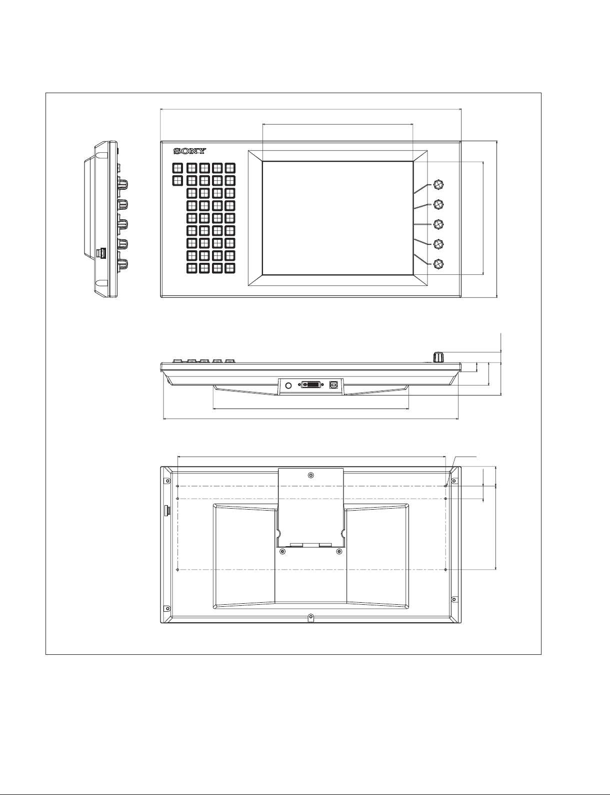
ICP-6511
424
213
13
160
32
220
46 14.5
276
416
378 6-M3
Unit: mm
17.7
27.3117.7
1-4 (E)
ICP-6520/6530/3000/6511
1-3-2. Installation Space
When the ICP-6520/6530/3000 is recessed into a control console or similar, make holes as shown below
into the control console with the following dimensions.
n
For the procedure of installation to the control console, refer to Section 1-4.
ICP-6520
Be sure to have an open space behind the cables of the connectors on the ICP-6520, shown as the “open
space at A” in the illustrations.
“Open space at A
70
40
8Ф identical
configuration
Clearance hole of parts with
the depth of 3 mm or more
B-B
41.3
4-M4
269 to 272
41.3
A
5.8
3.8
10
88.888.8
205.8
68 132
1157 to 1160
1136.6
B
“Open space at
A”
B
725
?0.5
”Hole”
A-A
70
5.8
A
11. 5
(Recommendation)
Unit: mm
ICP-6520/6530/3000/6511
1-5 (E)
ICP-6530
12Ф identical
configuration
Clearance hole of parts with
B-B
the depth of 3 mm or more
400 to 403
6-M4
R
41.3 41.3 41.3
A
1157 to 1160
5.8 5.8
3.8
88.8
88.8
132 132
88.8
10
68
1136.6
B
B
A-A
?0.5
”Hole”
11. 5
(Recommendation)
Unit: mm
A
ICP-3000
B-B
41.341.341.3
400 to 403
6-M4
R
A
12Ф identical
configuration
Clearance hole of parts with
the depth of 3 mm or more
823.6 to 826.6
803.2
?0.5
5.8 5.8
3.8
B
”Hole”
88.8 88.8 88.8
10
68 132 132
B
A
11. 5
(Recommendation)
1-6 (E)
A-A
Unit: mm
ICP-6520/6530/3000/6511

1-4. Installing the ICP-6520/6530/3000
2. Remove the module covers on both sides.
n
When installing the ICP-6520, ICP-6530 and ICP-3000
into the control console, be sure to install it with two
persons or more.
Install these by following the procedure described below.
* The illustration indicates ICP-3000.
Parts required
. For the ICP-6530/3000
Screws (B4 x 6): 6 pcs
. For the ICP-6520
Screws (B4 x 6): 4 pcs
1. Raise the control panel with two or more people, and
then the other person holds the control panel and fits it
into the control console.
Control panel
Module cover
Control panel
Module cover
3. Remove the innermost module. (Refer to “1-11. Removing the Module”.)
Module
ICP-6520/6530/3000/6511
Control console
1-7 (E)
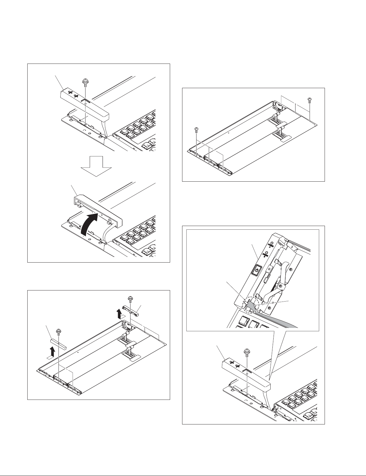
4. Remove the screw, then slowly move the cap (SW) in
the direction of the arrow.
Cap (SW)
PSW3 x 8
Cap (SW)
6. Secure the control panel to the control console with the
screws.
Number of screws
ICP-6530, ICP-3000: 6 pcs
ICP-6520: 4 pcs
B4 x 6
B4 x 6
7. Attach the cap (SW) with the screw.
n
When attaching the cap, be careful not to allow the
harness to be slackened in the portion A.
5. Remove the screws, then remove the cap (L) and cap
(R) in the direction of the arrows.
PSW3 x 8
Cap (L)
PSW3 x 8
Cap (R)
A
Cap (SW)
Cap (SW)
Harness
PSW3 x 8
1-8 (E)
ICP-6520/6530/3000/6511
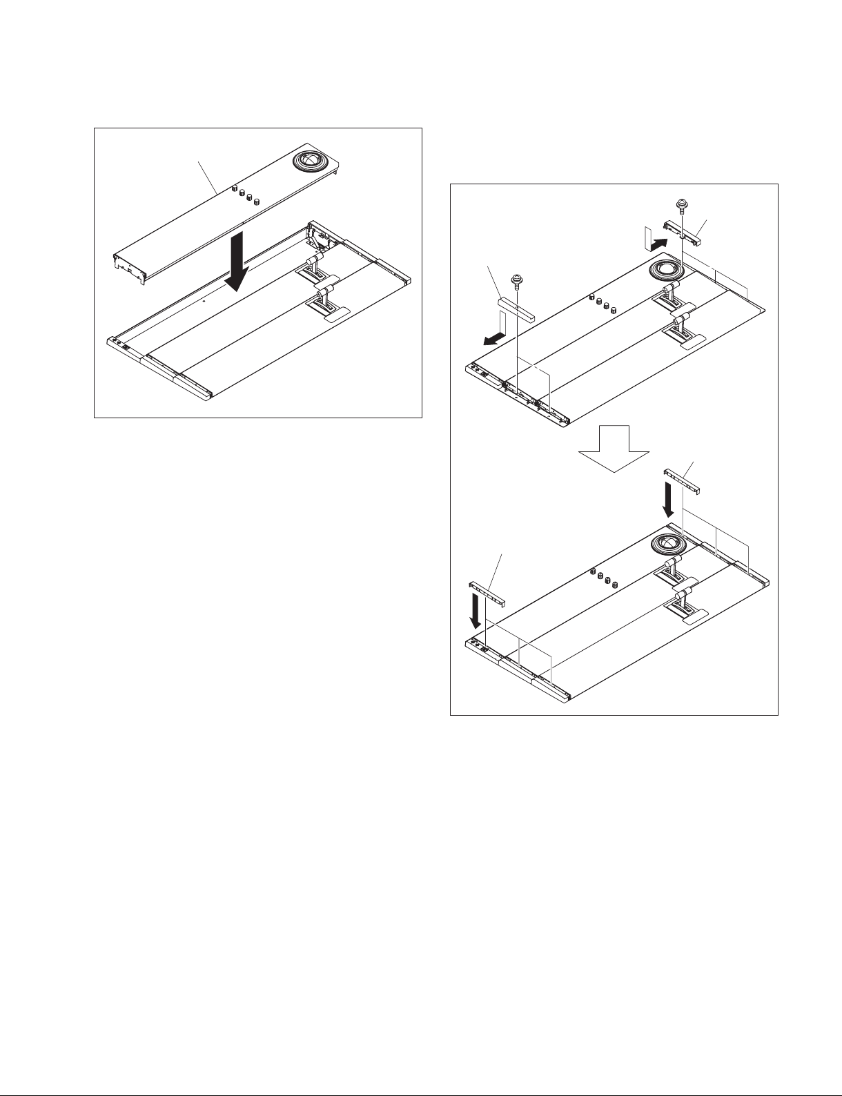
8. Attach the innermost module.
Module
9. Attach the cap (L) and cap (R) with the screw respectively in the direction of the arrows.
Then, attach the module covers in the direction of the
arrows.
Cap (L)
Module cover
PSW3 x 8
PSW3 x 8
Cap (R)
Module cover
ICP-6520/6530/3000/6511
1-9 (E)
 Loading...