

Sony ICFCD-843-V Service manual
ICF-CD843V
SERVICE MANUAL
Ver 1.0 2004.02
SPECIFICATIONS
US Model
Model Name Using Similar Mechanism ICF-CD853V
Optical Pick-up Block Name KSM-213RDP
Optical Pick-up Name KSS-213R
AUDIO POWER SPECIFICATIONS
POWER OUTPUT AND TOTAL HARMONIC
DISTORTION
With 4−ohm loads, both channels driven from
100 − 10 000 Hz; rated 1.0 W per channel-minimum
RMS power, with no more than 10% total harmonic
distortion in AC operation.
CD player section
System: Compact disc digital audio system
Laser diode properties:
Material: GaAlAs
Wavelength: 780 nm
Emission duration: Continuous
Laser output: Less than 44.6 µW
(This output is the value measured at a distance of
about 200 mm from the objective lens surface on
the optical pick-up block with 7 mm aperture.)
Frequency response: 20-20 000 Hz
Wow and flutter: Below measurable limit
+1
dB
−1.5
Radio section
Frequency range:
TV: 2 − 13 ch
WEATHER: 1 − 7 ch
FM: 87.5 − 108 MHz
AM: 530 − 1 710 kHz
General
Time display: 12-hour system
Speaker: 66 mm (2
Power outputs:
1.2 W + 1.2 W (at 10% harmonic distortion)
Power requirements: 120 V AC, 60 Hz
Dimensions:
Approx. 185.5 × 176 × 210.5 mm (w/h/d)
(Approx. 7
projecting parts and controls
Mass: Approx. 1 780 g (3 lb 15
Design and specifications are subject to change
without notice.
5
/
8
inches) dia., 4
3
/8 × 7 × 8 3/8 inches) incl.
oz)
TV/WEATHER/FM/AM CD CLOCK RADIO
9-877-625-01 Sony Corporation
2004B05-1 Personal Audio Company
C 2004.02 Published by Sony Engineering Corporation
ICF-CD843V
TABLE OF CONTENTS
1. SERVICING NOTES .............................................. 3
2. GENERAL .................................................................. 4
3. DISASSEMBLY
3-1. Disassembly Flow ........................................................... 5
3-2. Rear Cabinet Assy........................................................... 6
3-3. CD Lid ............................................................................. 6
3-4. Upper Cabinet Assy ........................................................ 7
3-5. MAIN Board ................................................................... 7
3-6. CD Block......................................................................... 8
3-7. Optical Pick-up (KSS-213R) .......................................... 8
4. ELECTRICAL ADJUSTMENTS
Tuner Section ................................................................. 9
CD Section ..................................................................... 11
5. DIAGRAMS
5-1. Block Diagram – CD Section – .................................... 12
5-2. Block Diagram – MAIN Section – ............................... 13
5-3. Note for Printed Wiring Board and
Schematic Diagrams ....................................................... 14
5-4. Printed Wiring Board – CD Section – .......................... 16
5-5. Schematic Diagram – CD Section – ............................. 17
5-6. Printed Wiring Board – MAIN Section – ..................... 18
5-7. Printed Wiring Boards – POWER Section – ................ 19
5-8. Schematic Diagram – MAIN section (1/2) – ............... 20
5-9. Schematic Diagram – MAIN section (2/2) – ............... 21
5-10. Printed Wiring Boards – PANEL Section – ................. 22
5-11. Schematic Diagram – PANEL Section – ...................... 23
6. EXPLODED VIEWS
6-1. Cabinet Section ............................................................... 27
6-2. Upper Cabinet Section .................................................... 28
6-3. Front Cabinet Section ..................................................... 29
6-4. Rear Cabinet Section ...................................................... 30
6-5. Optical Pick-up Section (KSM-213RDP) ...................... 31
7. ELECTRICAL PARTS LIST .............................. 32
SAFETY CHECK-OUT
After correcting the original service problem, perform the following safety check before releasing the set to the customer:
Check the antenna terminals, metal trim, “metallized” knobs,
screws, and all other exposed metal parts for AC leakage.
Check leakage as described below.
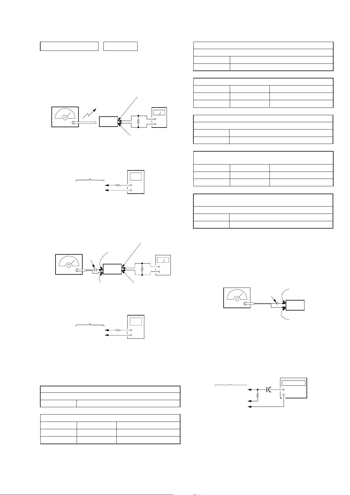
LEAKAGE TEST
The AC leakage from any exposed metal part to earth ground and
from all exposed metal parts to any exposed metal part having a
return to chassis, must not exceed 0.5 mA (500 microamperes).
Leakage current can be measured by any one of three methods.
1. A commercial leakage tester, such as the Simpson 229 or RCA
WT -540A. Follo w the manufacturers’ instructions to use these
instruments.
2. A battery-operated AC milliammeter . The Data Precision 245
digital multimeter is suitable for this job.
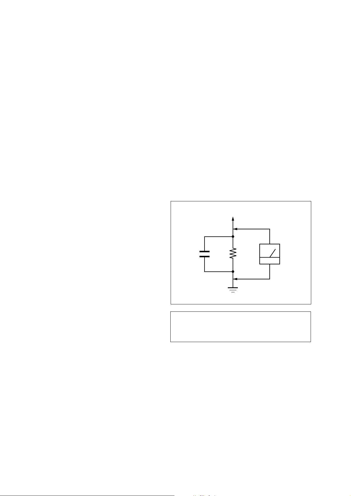
3. Measuring the voltage drop across a resistor by means of a
VOM or battery-operated AC voltmeter. The “limit” indication is 0.75 V, so analog meters must have an accurate lowvoltage scale. The Simpson 250 and Sanwa SH-63T rd are e xamples of a passive VOM that is suitable. Nearly all battery
operated digital multimeters that have a 2 V AC range are suitable. (See Fig. A)
To Exposed Metal
Parts on Set
1.5 k
0.15 µF
Fig. A. Using an AC voltmeter to check AC leakage.
Ω
Earth Ground
AC
voltmeter
(0.75 V)
Notes on chip component replacement
•Never reuse a disconnected chip component.
• Notice that the minus side of a tantalum capacitor may be damaged by heat.
Flexible Circuit Board Repairing
•Keep the temperature of the soldering iron around 270 ˚C during repairing.
• Do not touch the soldering iron on the same conductor of the
circuit board (within 3 times).
• Be careful not to apply force on the conductor when soldering
or unsoldering.
2
CAUTION
Use of controls or adjustments or performance of procedures
other than those specified herein may result in hazardous radiation exposure.
About CD-Rs/CD-RWs
This unit is compatible with CD-Rs/CD-RWs but
playback capability may vary depending on the
quality of the disc, the recording device and
application software.
SAFETY-RELATED COMPONENT WARNING!!
COMPONENTS IDENTIFIED BY MARK 0 OR DOTTED
LINE WITH MARK 0 ON THE SCHEMATIC DIAGRAMS
AND IN THE PARTS LIST ARE CRITICAL TO SAFE
OPERATION. REPLACE THESE COMPONENTS WITH
SONY PARTS WHOSE PART NUMBERS APPEAR AS
SHOWN IN THIS MANUAL OR IN SUPPLEMENTS PUBLISHED BY SONY.
SECTION 1
SER VICING NOTES
ICF-CD843V
NOTES ON HANDLING THE OPTICAL PICK-UP
BLOCK OR BASE UNIT
The laser diode in the optical pick-up block may suffer electrostatic break-down because of the potential difference generated
by the charged electrostatic load, etc. on clothing and the human
body.
During repair, pay attention to electrostatic break-down and also
use the procedure in the printed matter which is included in the
repair parts.
The flexible board is easily damaged and should be handled with
care.
NOTES ON LASER DIODE EMISSION CHECK
The laser beam on this model is concentrated so as to be focused
on the disc reflective surface by the objective lens in the optical
pick-up block. Therefore, when checking the laser diode emission, observe from more than 30 cm away from the objectiv e lens.
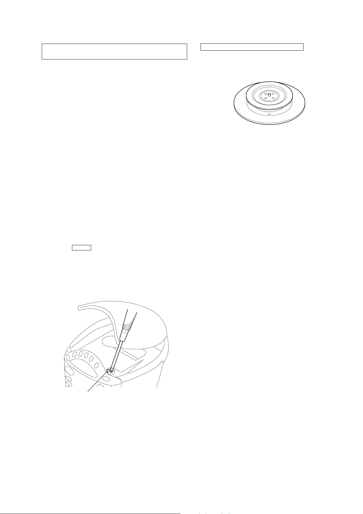
LASER DIODE AND FOCUS SEARCH OPERATION
CHECK
During normal operation of the equipment, emission of the laser
diode is prohibited unless the upper lid is closed while turning ON
the S302. (push switch type)
The following checking method for the laser diode is operable.
• Method
Emission of the laser diode is visually checked.
1. Open the upper lid.
2. Push the S302 as shown in Fig.1.
Note: Do not push the detection lever strongly, or it may be bent or dam-
aged.
3. Press the CD u button.
4. Check the object lens for confirming normal emission of the
laser diode. If not emitting, there is a trouble in the automatic
power control circuit or the optical pick-up.
In this operation, the object lens will move up and down 2
times along with inward motion for the focus search.
CHUCK PLATE JIG ON REPAIRING
On repairing CD section, playing a disc without the CD lid, use
Chuck Plate Jig.
• Code number of Chuck Plate Jig: X-4918-255-1
S302
Fig.1 Method to push the S302
3
ICF-CD843V
SECTION 2
GENERAL
This section is extracted from
instruction manual.
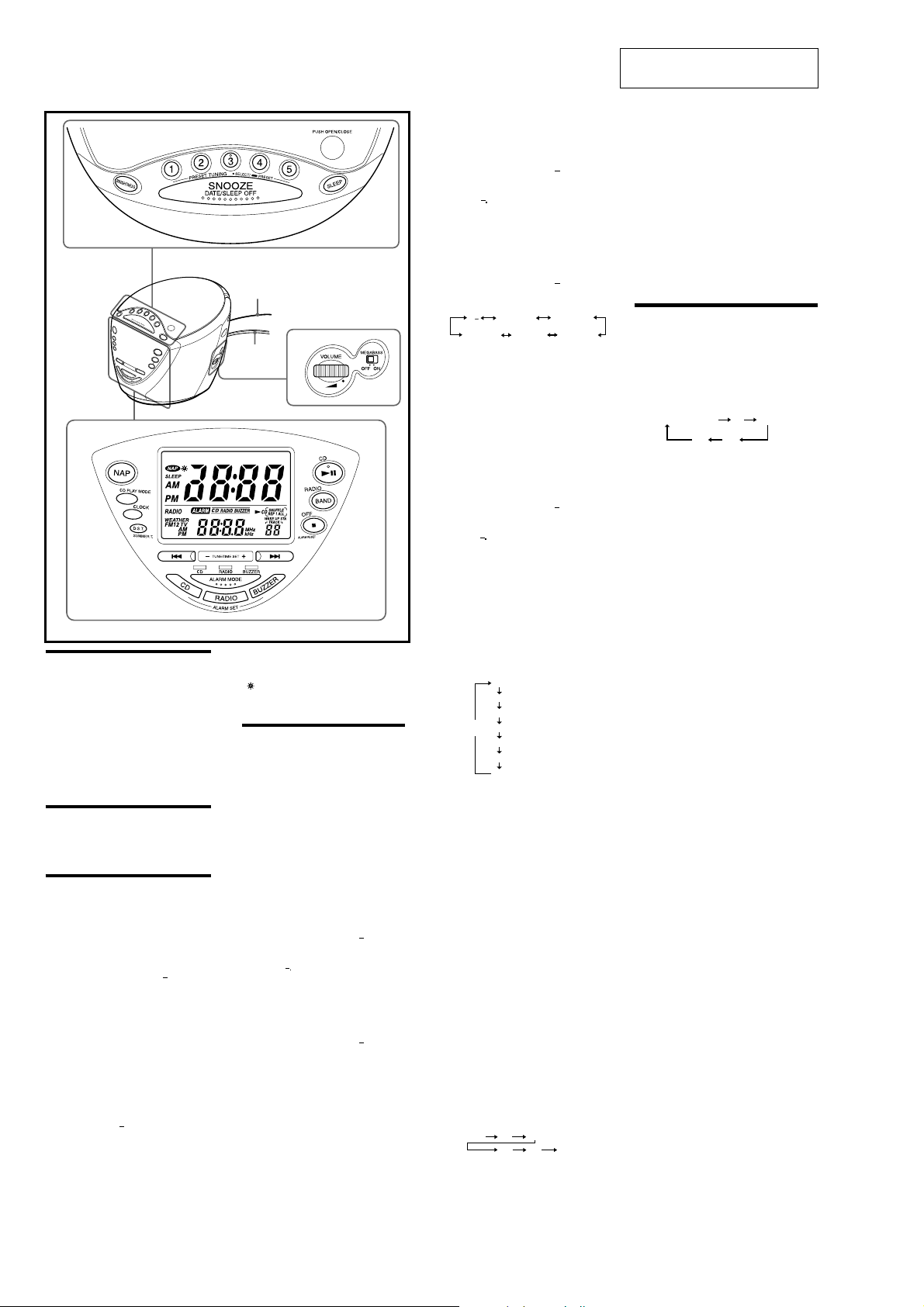
Features
• TV/WEATHER/FM/AM 4 band PLL (phase locked
loop) synthesized clock radio
• Easy preset digital tuning with 25 memory presets
• Built-in CD player with CD-R/RW playback
function
• Easy to see large Display with small footprint.
•Triple Alarm (Radio, buzzer or CD) with the
extendable snooze function.
• Easy nap timer —one push operation.
• LCD with backlight which has a brightness control
switch.
•D.S.T. (Daylight Saving Time) −Summer time
calculation.
Setting the Brightness
of the Backlight
Press BRIGHTNESS to select high, middle or low for
the display according to your preference.
Setting the Clock
and Date
1
Plug in the clock radio.
The display will flash AM 12:00 .
2
Press CLOCK for a few seconds.
You will hear a beep and the year will start to
flash in the display.
3
Press TUNE/TIME SET + or until the
correct year appears in the display.
4
Press CLOCK once.
5
Repeat steps 3 and 4 to set the month, day,
hour, and minute.
After setting the minutes, press CLOCK to start
the clock, and you will hear two short beeps.
To display the year and date, press
SNOOZE•DATE/SLEEP OFF once for the date,
and within 4 seconds press it again for the year. The
display shows the date or year for a few seconds and
then changes back to the current time.
To set the current time rapidly, hold down
TUNE/TIME SET + or
In step 5, when you press CLOCK after the minute
setting to activate the clock, the seconds start counting
from zero.
.
The PRESET TUNING 3 button has a
tactile dot.
FM wire
antenna
AC power
cord
The CD u button has a tactile dot.
To change the display to the
daylight saving time (summer time) indication
Press D.S.T./SUMMER T.
summer time.
To deactivate the summer time function, press
D.S.T./SUMMER T. again.
Setting the Alarm
This clock radio is equipped with 3 alarm modes−
CD, radio and buzzer. Before setting the alarm, make
sure to set the clock (see Setting the Clock and
Date ).
There is a tactile dot
beside volume to show
the direction to turn up
the volume.
is displayed and the time indication changes to
To Set the Alarm Time
To Set the CD Alarm:
For the CD alarm, the track you specified as the
Wake-up track is played first.
(If the CD play mode is set to SHUFFLE or
SHUFFLE REP , however, all the tracks are played
in random order.)
1
With the alarm turned on, adjust the volume
to the level you require.
2
Press ALARM SET CD for a few seconds.
ALARM , CD appear on the display.
After one beep, ALARM and the hour will start
to flash in the display.
3
Press TUNE/TIME SET + or until the
desired hour appears.
To set the hour rapidly, hold down TUNE/TIME
SET + or
4
Press ALARM SET CD.
The minute will flash.
5
Repeat step 3 to set the minute and press
ALARM SET CD.
The wake-up track number flashes on the display.
6
Press TUNE/TIME SET + or to select
the desired wake-up track number.
The wake-up track number can be set up to 99.
7
Press ALARM SET CD.
Two short beeps will confirm the setting.
To Set the Radio Alarm:
For the radio alarm, the station you specified as the
Wake-up station is played.
1
Tune into a station and adjust the volume.
2
Press ALARM SET RADIO for a few
seconds.
ALARM and RADIO appear on the display.
After one beep, ALARM and the hour will start
to flash on the display.
3
Press TUNE/TIME SET + or until the
desired hour appears.
To set the hour rapidly, hold down TUNE/TIME
SET + or
4
Press ALARM SET RADIO.
The minute will flash.
5
Repeat step 3 to set the minute and press
ALARM SET RADIO.
WAKE UP STA appears and the preset number
flashes on the display.
6
Press TUNE/TIME SET + or to select
the wake-up station.
Preset number changes in the order as follows:
You can directly select the desired wake-up
station by pressing RADIO•BAND or the
PRESET TUNING button while the indication
7
Press ALARM SET RADIO.
Two short beeps will confirm the setting.
AM P1 to 5 FM1 P1 to 5
P
P1 to 5
P− is the last received station.
P− is not displayed.
FM2 P1 to 5TV P1 to 5WEATHER
To Set the Buzzer Alarm:
1
Press ALARM SET BUZZER for a few
seconds.
ALARM and BUZZER appear on the display.
After one beep, ALARM and the hour will start
to flash on the display.
2
Press TUNE/TIME SET + or until the
desired hour appears.
To set the hour rapidly, hold down TUNE/TIME
SET + or
3
Press ALARM SET BUZZER.
The minute will flash.
4
Repeat step 2 to set the minute and press
ALARM SET BUZZER.
Two short beeps will confirm the setting.
To Set the Alarm Mode
Before setting the alarm mode, be sure to set the alarm
time. (See To Set the Alarm Time .)
Repeat the pressing of ALARM MODE to select the
alarm mode you want. Every time you press ALARM
MODE, CD/RADIO/BUZZER indicator changes in
the order as follows:
The alarm time which plays or sounds next is
displayed.
To Check the Alarm Setting
For ALARM SET CD, pressing once displays the
alarm time, pressing twice displays the wake-up track
number.
For ALARM SET RADIO, pressing once displays
the alarm time, pressing twice displays the wake-up
station.
For ALARM SET BUZZER, pressing once displays
the alarm time.
The display shows the alarm setting for a few seconds
and then returns to the previous display.
Alarm time in CD alarm, radio alarm and buzzer
alarm is set at AM 12:00 when you purchased the
unit.
ALARM ON—
If you set the CD alarm and there is no disc in the CD
player, the buzzer alarm will sound in its place at the
time set.
For the buzzer alarm, the beeping of the alarm
becomes more rapid after every few seconds in three
progressive stages.
Note
When CD, radio and buzzer alarms are set for the
same time, the CD alarm takes precedence. If the CD
alarm is not set, the radio alarm takes precedence.
To Doze for a Few More Minutes
Press SNOOZE•DATE/SLEEP OFF.
The CD, radio or buzzer alarm turns off but will be
automatically activated again after about 10 minutes.
Every time you press SNOOZE•DATE/SLEEP
OFF, the snooze time changes as follows:
CD
RADIO
BUZZER
CD+RADIO
OFF
CD+BUZZER
RADIO+BUZZER
CD+RADIO+BUZZER
20
10
40
30
60
50
The display shows the snooze time for a few seconds
and returns to show the current time. When you press
SNOOZE•DATE/SLEEP OFF after the current time
appears, the snooze time starts from 10 minutes again.
The maximum length of the snooze time is 60
minutes.
ALARM OFF—
The CD, radio, or buzzer alarm is turned off
automatically after 60 minutes.
To Stop the Alarm
Press OFF x•ALARM RESET to turn off the alarm.
The alarm will come on again at the same time the
next day.
To Deactive the Alarm
Press ALARM MODE repeatedly until CD/RADIO/
BUZZER indicator go off.
Setting the Sleep
Timer
You can fall asleep to the CD or the radio using the
automatically after a preset duration.
Press SLEEP during CD or radio play.
You can set the sleep timer to durations of 90, 60, 30,
or 15 minutes. Every push changes the display as
follows:
off (current time)
SLEEP will appear in the display when the duration
time is set.
The CD or the radio will play for the time you set,
then shut off.
To turn off the CD or the radio before the preset time,
press SNOOZE•DATE/SLEEP OFF.
90
60
15
30
4
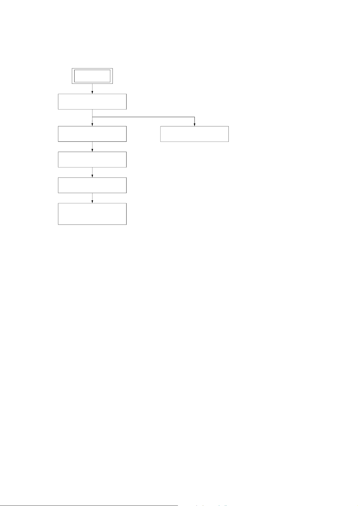
• This set can be disassembled in the order shown below.
3-1. DISASSEMBLY FLOW
SET
3-2. Rear Cabinet Assy
(Page 6)
ICF-CD843V
SECTION 3
DISASSEMBLY
3-4. Upper Cabinet Assy
(Page 7)
3-5. MAIN Board
(Page 7)
3-6. CD Block
(Page 8)
3-7. Optical Pick-up
(KSS-213R)
(Page 8)
3-3. CD Lid
(Page 6)
5
ICF-CD843V
)
)
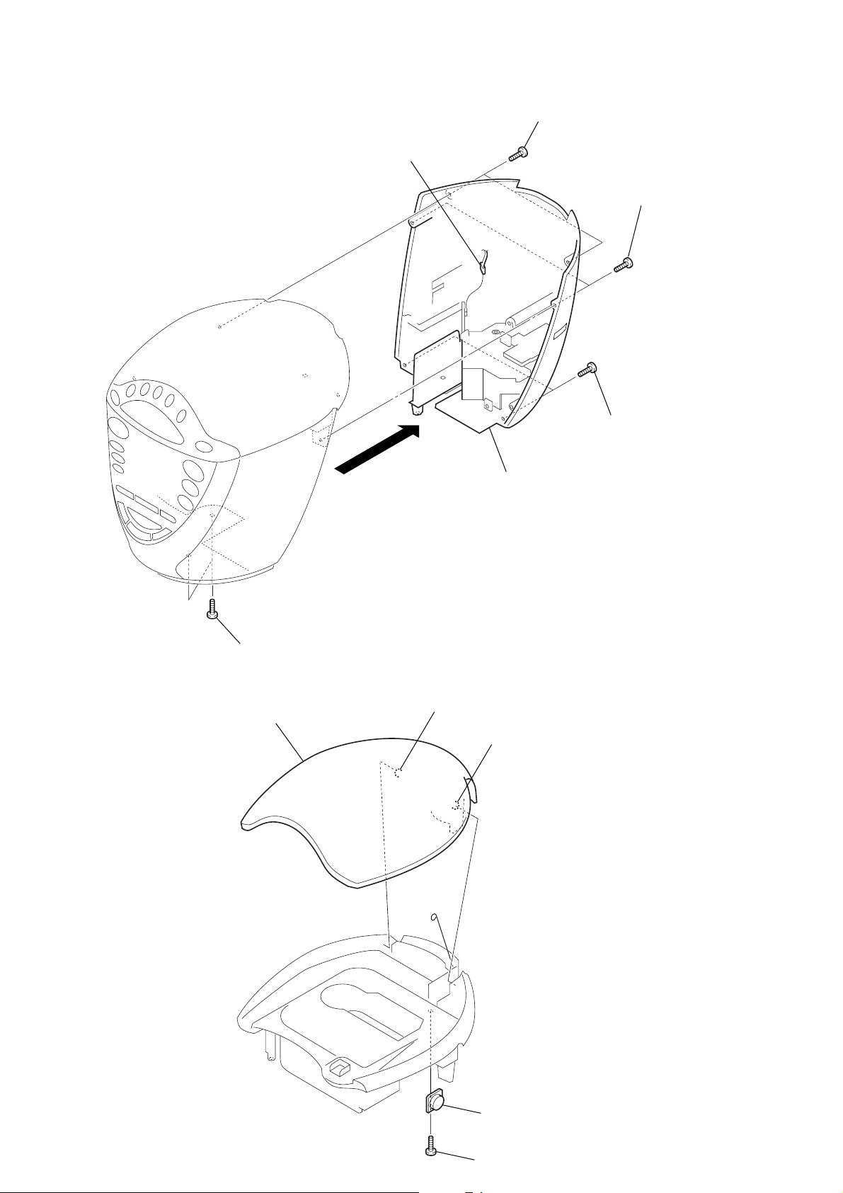
Note: Follow the disassembly procedure in the numerical order given.
3-2. REAR CABINET ASSY
5
connector (CN901)
4
3
two screws (B3)
6
rear cabinet assy
3
two screws (B3)
2
two screws (B2.6
3-3. CD LID
1
two screws (B2.6)
4
CD lid
3
boss
3
boss
2
damper
1
6
screw (B3
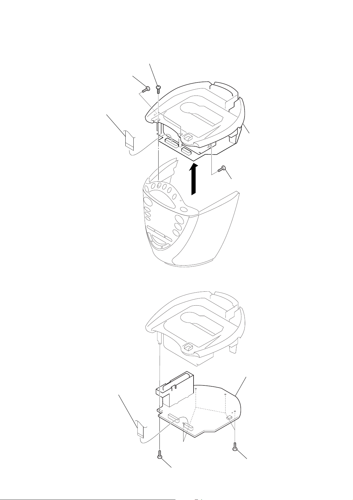
3-4. UPPER CABINET ASSY
y
s
1
screw (B2.6)
4
flexible flat cable (20core)
(CN301)
2
two screws (B3)
3
1
screw (B2.6)
5
upper cabinet ass
ICF-CD843V
3-5. MAIN BOARD
1
flexible flat cable (14core)
(CN302)
3
MAIN board
2
screw (B3)
2
four screw
(B3)
7
ICF-CD843V
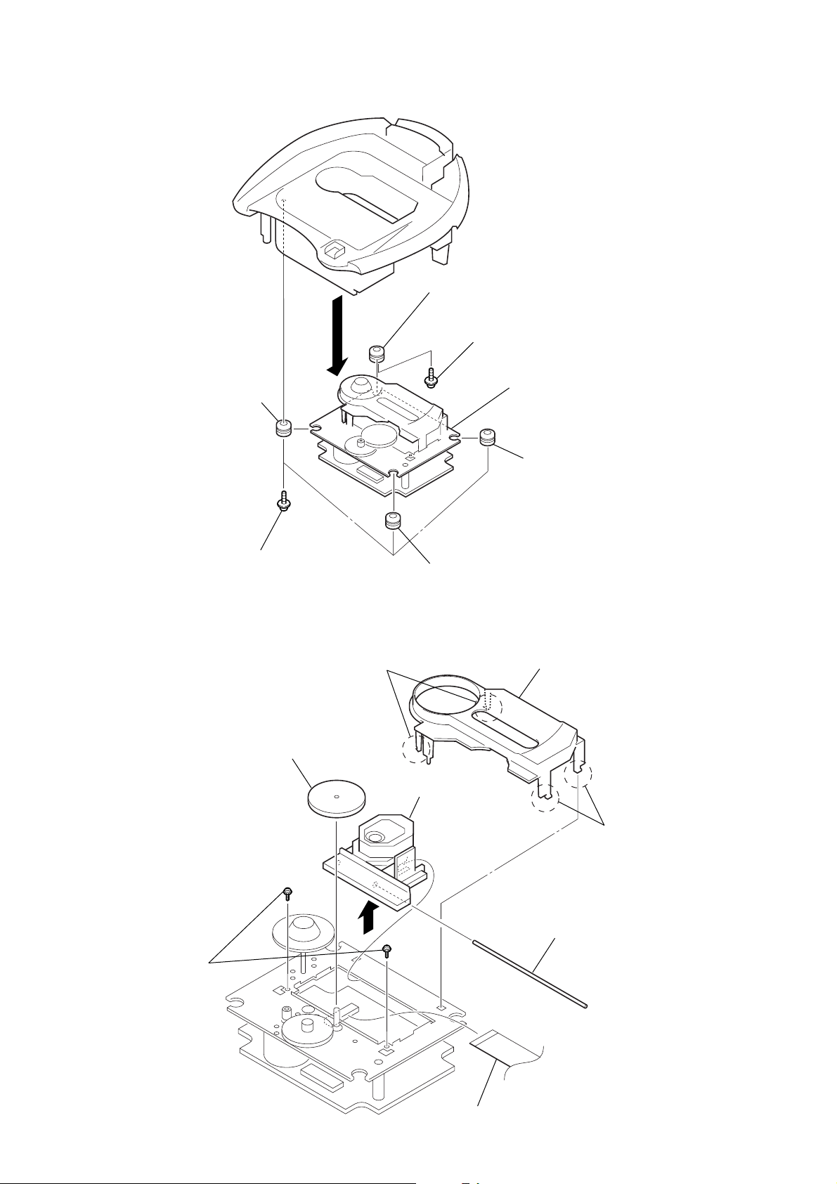
)
3-6. CD BLOCK
3
vibration proof (green)
2
3
vibration proof (green)
1
screw (B2.6)
4
CD block
3-7. OPTICAL PICK-UP
(KSS-213R)
1
three screws
(B2.6)
3
gear (B)
two claws
1
8
optical pick-up (KSS-213R)
3
vibration proof (red)
3
vibration proof (red
2
CD cover
1
two claws
5
6
sled shaft
4
two screws (M2)
7
flexible flat cable (16core) (CNP701)
8
SECTION 4
ELECTRICAL ADJUSTMENTS
ICF-CD843V
TUNER SECTION 0 dB=1 µV
[AM]
Setting:
Function : RADIO
RADIO BAND button : AM
MAIN board
AM RF signal
generator
30% amplitude
modulation by
400 Hz signal
Output level:
as low as possible
Put the lead-wire
antenna close to
the set.
MAIN board
TP (VT)
TP (FM GND)
set
100 k
[FM/TV]
Setting:
Function : RADIO
RADIO BAND button: FM or TV or WEATHER
CN303 pin
4.0
Ω
MAIN board
CN303 pin
digital voltmeter
Ω
4
level meter
+
–
3
AM TRACKING ADJUSTMENT
Adjust for a maximum reading on level meter
L5 580 kHz
CT1 1,490 kHz
FM/TV (2 – 6 CH) VCO VOLTAGE CONFIRMATION
Adjustment Part Frequency Display Reading on Digital Voltmeter
Confirmation 108 MHz 15.0 ± 1.0 V
Confirmation TV 2 ch 2.35 ± 0.1 V
FM/TV (2 – 6 CH) TRACKING ADJUSTMENT
Adjust for a maximum reading on level meter
L2 TV 2 ch
CT2 108 MHz
TV (7 – 13 CH), WEATHER (1 – 7 CH)
VCO VOLTA GE CONFIRMATION
Adjustment Part Frequency Display Reading on Digital Voltmeter
Confirmation TV 13 ch 10.0 ± 1.0 V
Confirmation WEATHER 2 ch 4.6 ± 0.5 V
TV (7 – 13 CH), WEATHER (1 – 7 CH)
TRACKING ADJUSTMENT
Adjust for a maximum reading on level meter
L3 WEATHER 2 ch
CT3 TV 13 ch
MAIN board
FM RF signal
generator
0.01 µF
22.5 kHz frequency
deviation by 400 Hz
signal
Output level:
as low as possible
MAIN board
TP (AM GND)
MAIN board
TP (ANT)
MAIN board
TP (FM GND)
TP (VT)
set
digital voltmeter
Ω
100 k
CN303 pin
4.0
MAIN board
CN303 pin
4
level meter
Ω
+
–
3
•Repeat the procedures in each adjustment several times, and the
tracking adjustments should be finally done by the trimmer capacitors.
• Remove FM antenna in FM adjustment.
AM IF ADJUSTMENT
Adjust for a maximum reading on level meter
RV2 1,000 kHz
Adjustment Location: MAIN board (See page 10)
FM STEREO ADJUSTMENT
Setting:
Function: RADIO
RADIO BAND button: FM
FM RF SSG
µ
F
0.01
Carrier frequency : 87.5 MHz
Modulation : no modulation
Output level : 0.1 V (100 dB)
MAIN board
TP (ANT)
set
MAIN board
TP (FM GND)
1. Connect the frequency counter to TP (FMST) and TP (RADIO +B) as shown the figure below.
2. Tune the set to 87.5 MHz.
3. Adjust RV1 for 75.95 to 76.05 kHz reading on the frequency
counter.
frequency counter
MAIN board
TP (FMST)
TP (RADIO +B)
TP (FM GND)
1
33 k
µ
F/50 V
+
+
–
Ω
AM VCO VOLTA GE ADJUSTMENT
Adjustment Part Frequency Display Reading on Digital Voltmeter
L1 530 kHz 2.3 ± 0.05 V
Confirmation 1,710 kHz 8.7 ± 1.0 V
Adjustment Location: MAIN board (See page 10)
9
ICF-CD843V
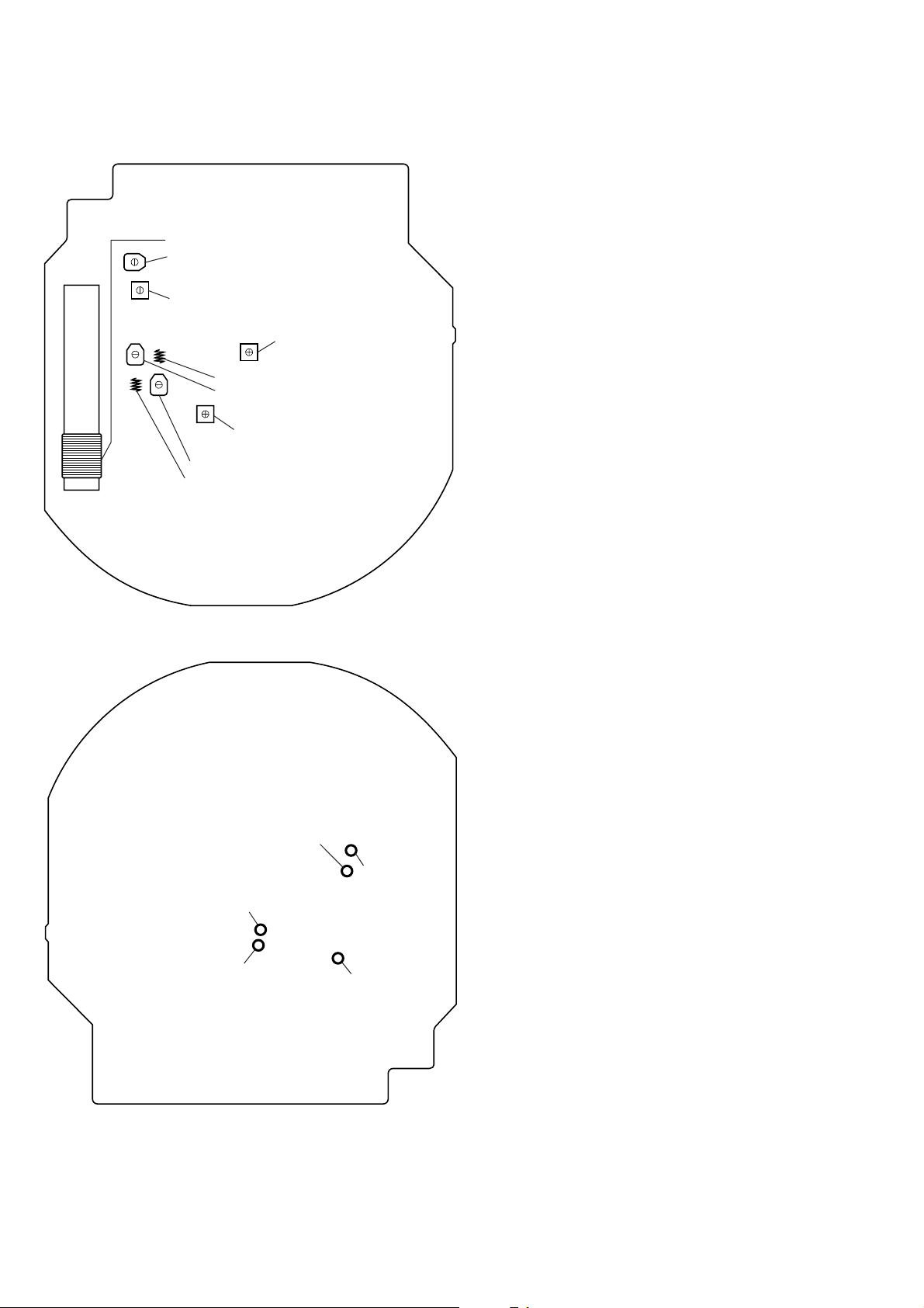
Adjustment Location:
– MAIN BOARD (Component Side) –
L5
AM T rac king Adjustment
}
CT1
L1 AM VCO Voltage Adjustment
L3 TV (7 – 13 ch)/Weather (1 – 7 ch)
CT3 }Tracking Adjustment
RV2 AM IF Adjustment
CT2
FM/TV (2 – 6 ch) Tracking Adjustment
}
L2
RV1 FM Stereo Adjustment
– MAIN BOARD (Conductor Side) –
TP
(AM GND)
TP
(RADIO +B)
TP
(FM GND)
TP
(ANT)
TP
(VT)
10

CD SECTION
CD section adjustments are done automatically in this set.
In case of operation check, confirm that focus bias.
FOCUS BIAS CHECK
1. Connect the oscilloscope to TP (RF) and TP (GND) on the CD
board.
2. Insert the disc (YEDS-18). (Part No. : 3-702-101-01)
3. Press the u (CD) button.
4. Confirm that the oscilloscope waveform is as shown in the
figure below. (eye pattern)
A good eye pattern means that the diamond shape (◊) in the
center of the waveform can be clearly distinguished.
• RF signal reference waveform (eye pattern)
VOLT/DIV: 0.2 V (with the 10: 1 probe in use.)
TIME/DIV: 500 ns
0.8
±
0.2 Vp-p
ICF-CD843V
When observing the eye pattern, set the oscilloscope
for AC range and raise vertical sensitivity.
Adjustment Location:
– CD BOARD (Conductor Side) –
IC701
TP (GND)
TP
(RF)
1111
ICF-CD843V
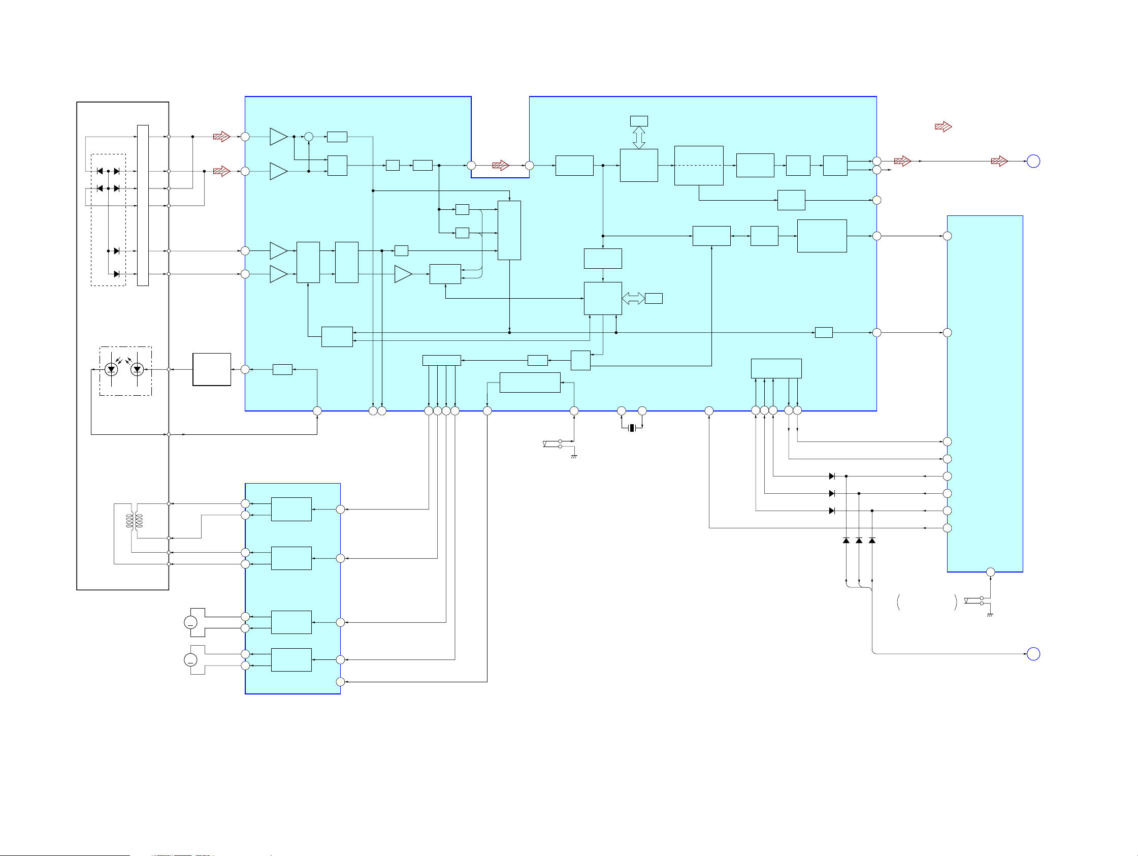
5-1. BLOCK DIAGRAM – CD Section –
SECTION 5
DIAGRAMS
DETECTOR
A
D
C
B
F
E
OPTICAL PICK-UP
(KSS-213R)
LASER DIODE
PD
LD
I-V AMP
RF AMP, FOCUS/TRACKING SERVO,
DIGITAL SIGNAL PROCESSOR,
CLV SERVO, D/A CONVERTER
A
D
C
B
F
E
LD
AUTOMATIC
POWER
CONTROL
Q701
FIN2
8
FIN1
7
TIN2
10
TIN1
9
LDD
80
TBAL
APC
LPF
+
MIX
LPF
AUDIO
ADJUST
LDS
79
TE
13FE15
IC701
EFM
RF
EQ
AGC
SW
TRACK
JUMP
S/H
TDO21FDO23SLDO22SPDO
20
4
PH
BH
A/D
GENERAL-PURPOSE
CONT4
25
3
PORTS
D/A
IN
SLISE LEVEL
CONTROL
RUPTURE
DETECT
SERVO
PROCESSOR
SW
CONT1
72
RAM
ERROR
CORRECTION
AUDIO CD
C1 – 2, C2 – 2
XIN
49 48
RAM
XOUT
INTERPOLATION
MUTE
ATTENUATION
DEEMPHASIS
CLV, CAV
CONTROL
RES
66
8FS
DIGITAL
FILTER
PLL
VCEC
COMMAND
INTERFACE
61CE62CL63DI64DO65
1 BIT
DAC
AUDIO
OUT
PROTECT INSERT,
WRQ
FRAME SYNC
DETECT,
EFM DECODE
DRF
LPF
LCHO
RCHO
DOUT
FSEQ
DRF
42
R-CH
45
39
31
67
• R-ch is omitted due to same as L-ch.
• SIGNAL PATH
: CD PLAY
41 FSEQ
57 DRF
SYSTEM
CONTROLLER
IC401 (1/2)
CD-L
A
(Page 13)
2-AXIS
DEVICE
(FOCUS)
PD
T+
T–
(TRACKING)
F+
1
F–
M702
(SLED)
M701
(SPINDLE)
S701
(LIMIT)
FOCUS/TRACKING COIL DRIVE,
SPINDLE/SLED MOTOR DRIVE
T+
12
T–
11
F+
17
F–
18
SL+
M
M
26
SL–
27
SP+
2
SP–
1
IC702
TRACKING
COIL DRIVE
FOCUS
COIL DRIVE
SLED
MOTOR DRIVE
SPINDLE
MOTOR DRIVE
TIN
FIN
SLIN
SPIN
9
19
25
3
7MUTE
X701
33.8688MHz
D306
D307
D308
D52
DI
D53
CLK
CE
D54
S302
CD LID OPEN/CLOSE
DETECT
50 WRQ
56 DATA-IN CD
54 DATA CD/RADIO
55 CLK CD/RADIO
53 LAT CD/RADIO
58 XRST
OPEN
39
DI, CLK, CE
B
(Page 13)
1212
 Loading...