

Sony ICFCD-825-RM Service manual
ICF-CD825RM
SERVICE MANUAL
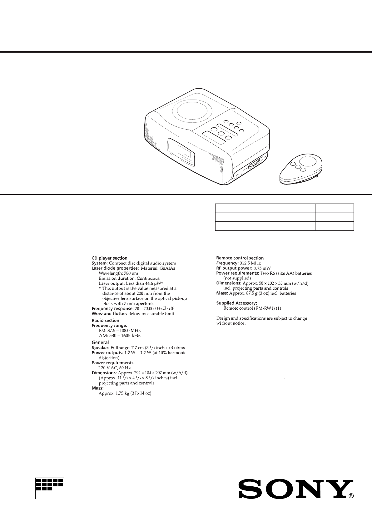
SPECIFICATIONS
US Model
Model Name Using Similar Mechanism CFD-550
Optical Device Name KSM-213BAN
Optical Pick-UP Name KSS-213B
MICROFILM
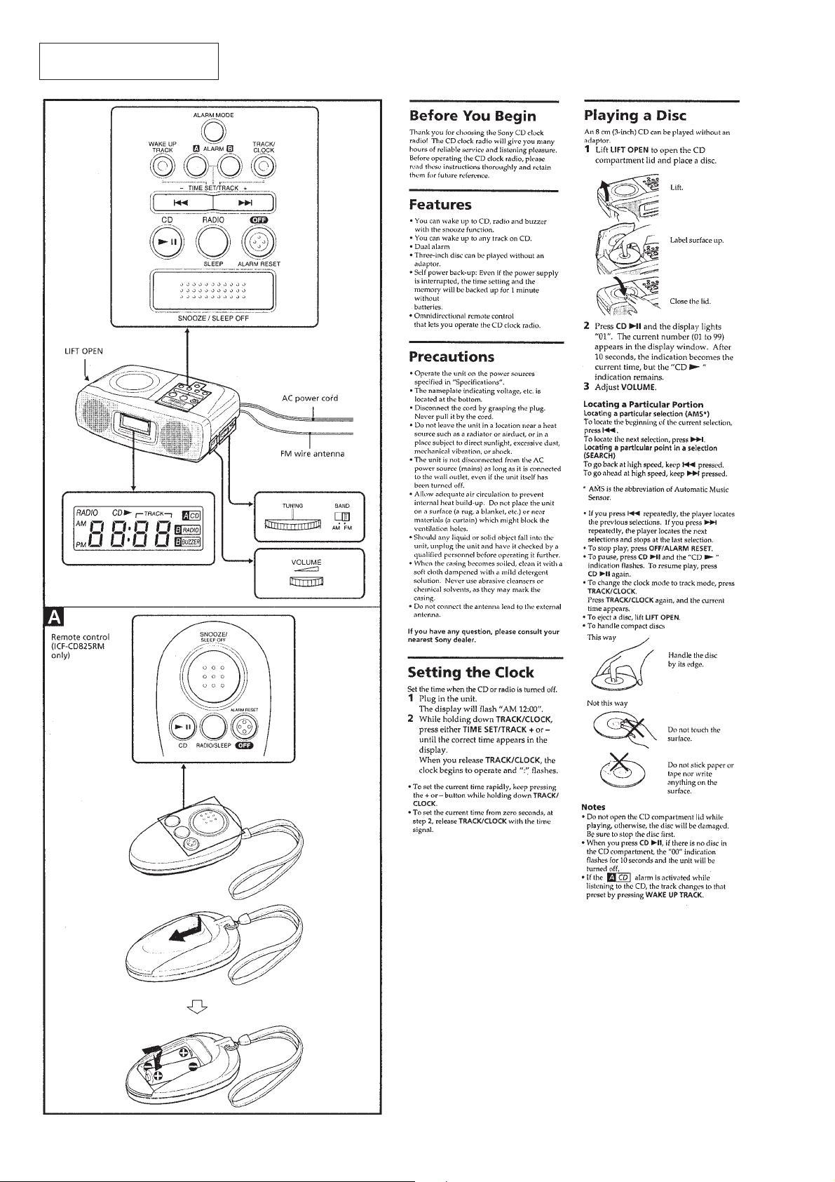
CD CLOCK RADIO
SECTION 1
SERVICING NOTES
TABLE OF CONTENTS
1. SERVICING NOTES............................................... 2
2. GENERAL ................................................................. 4
3. DISASSEMBLY ......................................................... 6
4. ELECTRICAL ADJUSTMENTS
• Tuner Section .............................................................. 9
• CD Section .................................................................. 11
• Remote Control Section .............................................. 14
5. DIAGRAMS
5-1. Printed Wiring Boards – MAIN Section – ..................... 20
5-2. Schematic Diagram – MAIN Section –.......................... 23
5-3. Schematic Diagram – RECEIVER Section –................. 27
5-4. Printed Wiring Boards – RECEIVER Section – ............ 28
5-5. Schematic Diagram
– REMOTE CONTROL Section – ................................. 29
5-6. Printed Wiring Board
– REMOTE CONTROL Section – ................................. 29
5-7. IC Pin Function Description ........................................... 34
6. EXPLODED VIEWS ................................................ 38
NOTES ON HANDLING THE OPTICAL PICK-UP
BLOCK OR BASE UNIT
The laser diode in the optical pick-up block may suffer electrostatic break-down because of the potential difference generated
by the charged electrostatic load, etc. on clothing and the human
body.
During repair, pay attention to electrostatic break-down and also
use the procedure in the printed matter which is included in the
repair parts.
The flexible board is easily damaged and should be handled with
care.
NOTES ON LASER DIODE EMISSION CHECK
The laser beam on this model is concentrated so as to be focused
on the disc reflective surface by the objective lens in the optical
pick-up block. Therefore, when checking the laser diode emission, observe from more than 30 cm away from the objective lens.
CHUCK PLATE JIG ON REPAIRING
On repairing CD section, playing a disc without the CD lid, use
Chuck Plate Jig.
• Code number of Chuck Plate Jig: X-4918-255-1
7. ELECTRICAL PARTS LIST ............................... 42
SAFETY-RELATED COMPONENT WARNING!!
COMPONENTS IDENTIFIED BY MARK ! OR DOTTED
LINE WITH MARK ! ON THE SCHEMATIC DIA GRAMS
AND IN THE PARTS LIST ARE CRITICAL TO SAFE
OPERATION. REPLACE THESE COMPONENTS WITH
SONY PARTS WHOSE PART NUMBERS APPEAR AS
SHOWN IN THIS MANU AL OR IN SUPPLEMENTS PUBLISHED BY SONY.
ATTENTION AU COMPOSANT AYANT RAPPORT
À LA SÉCURITÉ!
LES COMPOSANTS IDENTIFIÉS P AR UNE MARQUE !
SUR LES DIAGRAMMES SCHÉMATIQUES ET LA LISTE
DES PIÈCES SONT CRITIQUES POUR LA SÉCURITÉ
DE FONCTIONNEMENT. NE REMPLACER CES COMPOSANTS QUE PAR DES PIÈCES SONY DONT LES
NUMÉROS SONT DONNÉS DANS CE MANUEL OU
DANS LES SUPPLÉMENTS PUBLIÉS PAR SONY.
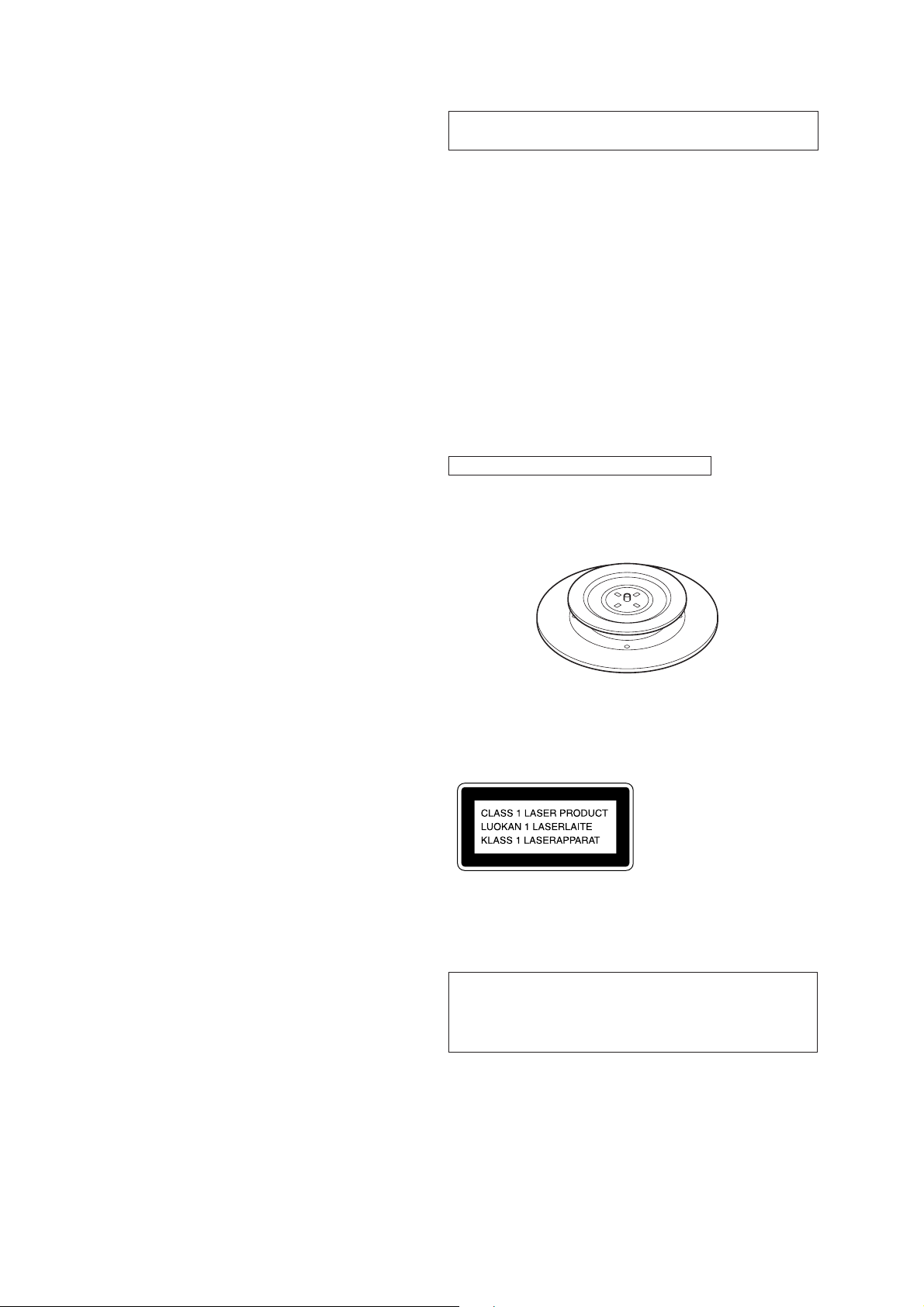
This Compact Disc player is classified as a CLASS 1
LASER product.
The CLASS 1 LASER PRODUCT label is located on the
bottom exterior.
CAUTION
Use of controls or adjustments or performance of procedures
other than those specified herein may result in hazardous radiation exposure.
Note on chip component replacement
• Never reuse a disconnected chip component.
• Notice that the minus side of a tantalum capacitor may be damaged by heat.
– 2 –
SAFETY CHECK-OUT
3
After correcting the original service problem, perform the following safety check before releasing the set to the customer:
Check the antenna terminals, metal trim, “metallized” knobs,
screws, and all other exposed metal parts for AC leakage.
Check leakage as described below.
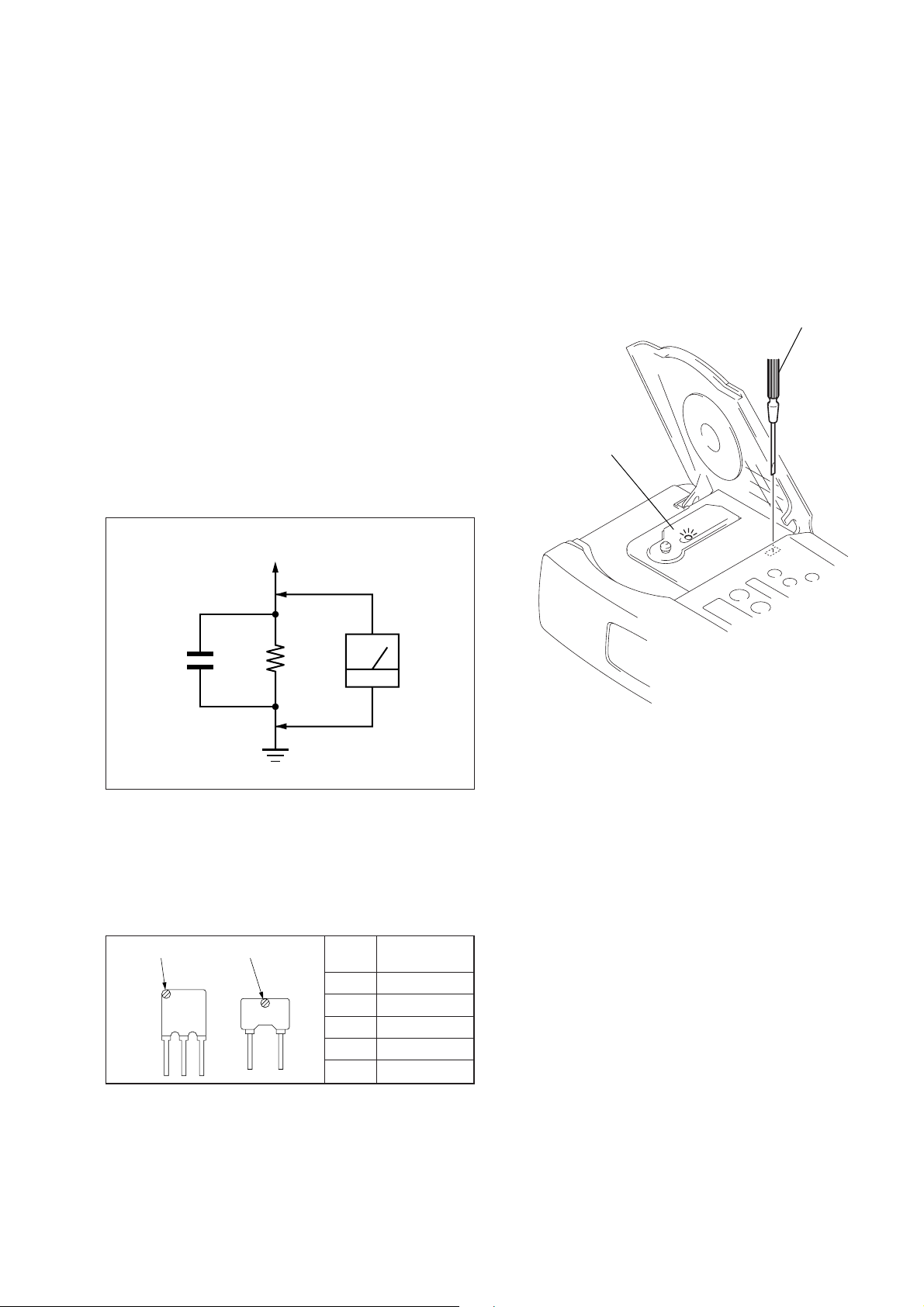
LEAKAGE TEST
The AC leakage from any exposed metal part to earth ground and
from all exposed metal parts to any exposed metal part having a
return to chassis, must not exceed 0.5 mA (500 microampers.).
Leakage current can be measured by any one of three methods.
1. A commercial leakage tester, such as the Simpson 229 or RCA
WT -540A. Follo w the manufacturers’ instructions to use these
instruments.
2. A battery-operated AC milliammeter. The Data Precision 245
digital multimeter is suitable for this job.
3. Measuring the voltage drop across a resistor by means of a
VOM or battery-operated AC voltmeter. The “limit” indication is 0.75 V, so analog meters must have an accurate lowvoltage scale. The Simpson 250 and Sanwa SH-63Trd are examples of a passive VOM that is suitable. Nearly all battery
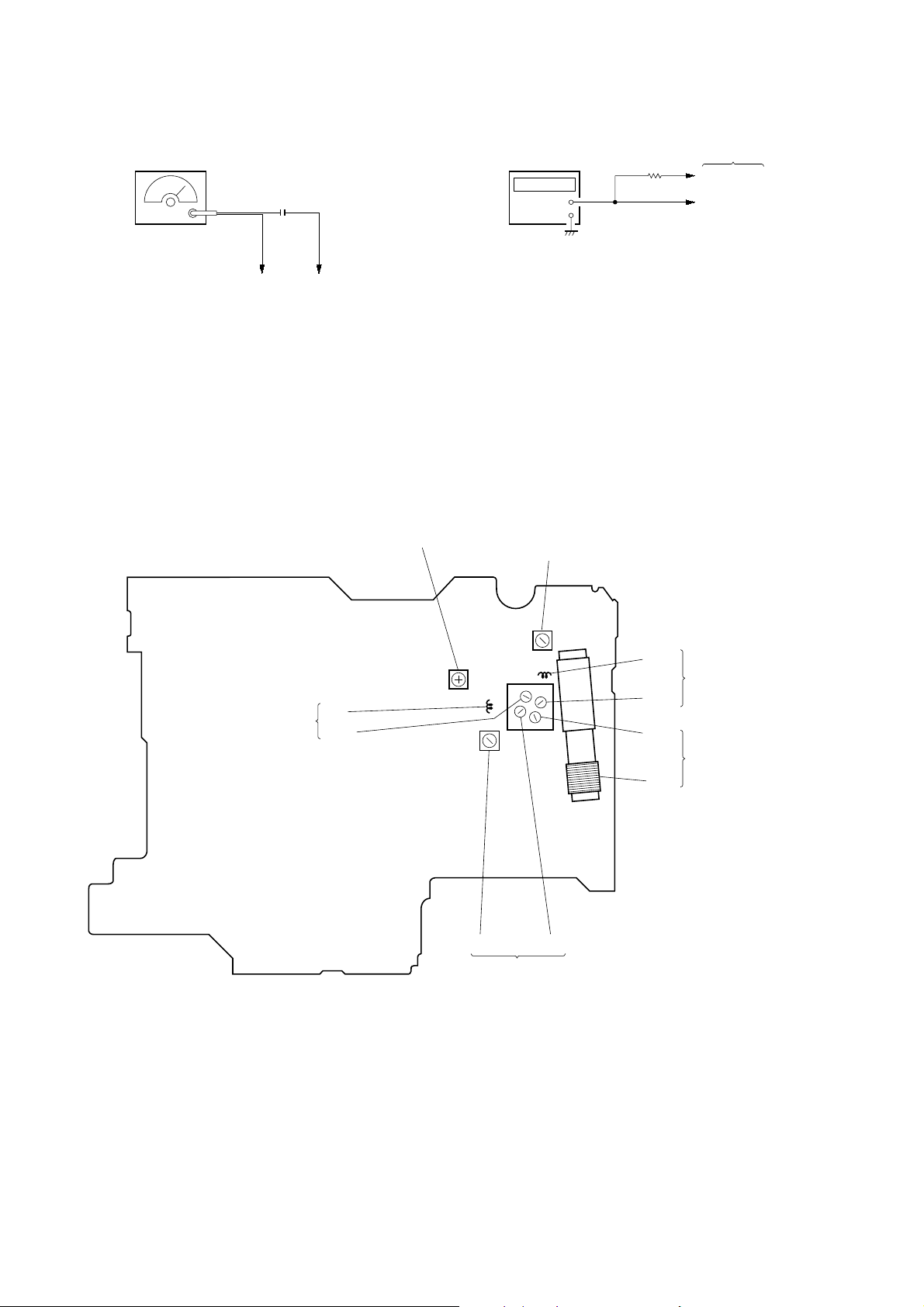
operated digital multimeters that have a 2 V A C range are suitable. (See Fig. A)
To Exposed Metal
Parts on Set
LASER DIODE AND FOCUS SEARCH
OPERATION CHECK
1. Open the CD lid.
2. Turn on S420 as following figure.
3. Confirm that the laser diode emission while observing the objecting lens. When there is no emission, Auto Power Control
circuit or Optical Pick-up is broken.
Objective lens moves up and down once for the focus search.
Insert a precision
screwdriver and
push S420.
laser diode
emission
1.5 k
0.15 µF
Fig. A. Using an AC voltmeter to check AC leakage.
Ω
Earth Ground
AC
voltmeter
(0.75 V)
• HOW TO CHANGED THE CERAMIC FILTERS
This model is used two ceramic filters of CF2, CF3.
You must use same type of color marked ceramic filters in order
to meet same specifications.
Therefore, the ceramic filter must change two pieces together since
it's supply two pieces in one package as a spare parts.
mark
CF2
mark
CF
mark
red 10.70 MHz
center
frequency
blue 10.67 MHz
orange 10.73 MHz
black 10.64 MHz
white 10.76 MHz
– 3 –
This section is extracted from
instruction manual.
SECTION 2
GENERAL
– 4 –
– 5 –
DISASSEMBLY
y
• This set can be disassembled in the order shown below.
SECTION 3
SET
Note: Follow the disassembly procedure in the numerical order given.
UPPER CABINET
ASS’Y
UPPER CABINET ASS’Y
2
CD LID ASS’Y
MAIN BOARD AND OPTICAL PICK-UP SECTION
DIAL POINTER SETTING
Open the CD lid ass’y.
3
two screws
(P3 × 14)
5
flat wire
(CN401)
3
screws
(P3 × 14)
1
screw
(P3 × 14)
4
upper cabinet ass’
6
connector
(CNP301)
– 6 –
3
three screws
(P3 × 14)

CD LID ASS’Y
1
Open the CD lid ass’y.
2
CD lid spring
5
CD lid ass’y
3
left hinge plate
4
right hinge plate
MAIN BOARD AND OPTICAL PICK-UP SECTION
4
3
!¡
connector
(CNP502)
lead wire
(CN901)
5
screw
(P3 × 14)
8
screw
(BTP3 × 10)
claw
9
optical pick-up section
2
switch board
4
screw (BTP3 × 10)
0
flat wire (CNP501)
7
screw (PTP3 × 10)
4
6
three screws
(BTP3 × 10)
main board
1
two connectors
(CNP651, 653)
– 7 –
DIAL POINTER SETTING
Note: Follow the assembly procedure in the numerical order given.
4
Set the MAIN board.
A
CV1
3
Turn the shaft CV1 to
the arrow direction from
the pattern side perfectly
(Fig. 3).
(Fig. 3)
2
Fit A portion and fit a claw to
the hole of axle side and catch
in to pointer gear (Fig. 2).
pointer
claw
(Fig. 2)
pointer
(Fig. 1)
1
Set the pointer at the marker
line (Fig. 1).
marker
– 8 –
SECTION 4
r
ELECTRICAL ADJUSTMENTS
PRECAUTION
• Adjustment should be performed in the order given.
TUNER SECTION 0 dB=1 µV
[FM]
Setting:
Function switch : RADIO
BAND switch : FM
FM RF SSG
0.01 µF
22.5 kHz frequency deviation
by 400 Hz signal.
Output level: as low as possible
FM lead wire antenna terminal
[AM]
Setting:
Function switch : RADIO
BAND switch : AM
AM RF SSG
Put the lead-wire
antenna close to
the set.
FM FREQUENCY COVERAGE ADJUSTMENT
Adjust for a maximum reading on level meter
L3 87.5 MHz
CT2 108.0 MHz
FM TRACKING ADJUSTMENT
Adjust for a maximum reading on level meter
L2 87.5 MHz
CT1 108.0 MHz
AM IF ADJUSTMENT
Adjust for a maximum reading on level meter
T1 455 kHz
AM FREQUENCY COVERAGE ADJUSTMENT
Adjust for a maximum reading on level meter
L4 530 kHz
CT4 1,605 kHz
AM TRACKING ADJUSTMENT
Adjust for a maximum reading on level meter
L1 600 kHz
CT3 1,400 kHz
30% amplitude modulation by
400 Hz signal.
Output level: as low as possible
level mete
4
Ω
set
speaker terminal
+
–
• Repeat the procedures in each adjustment se veral times, and the
frequency coverage and tracking adjustments should be finally
done by the trimmer capacitors.
– 9 –
FM STEREO Adjustment
d
g
g
Procedure:
FM RF SSG
0.01 µF
Carrier frequency: 98 MHz
Modulation: no modulation
Output level: 0.032 V (90 dB)
FM lead wire antenna terminal
’‘
1. Connect the frequency counter to 4 and 7 pins of IC1 as
shown the figure right.
2. Tune the set to 98 MHz.
3. Adjust RV1 for 76 kHz ± 500 Hz reading on frequenc y counter.
Adjustment Location:
RV1
FM Stereo Adjustment (76 kHz)
[MAIN Board] (Component Side)
Connection:
frequency counter
+
–
T1
AM IF Adjustment
33 k
Ω
MAIN boar
IC1 Pin
7
IC1 Pin
4
FM Frequency Coverage
Adjustment
L3
CT2
L4
AM Frequency Coverage
Adjustment
CT4
L2
CT1
CT3
L1
FM Trackin
Adjustment
AM Trackin
Adjustment
– 10 –
CD SECTION
MAIN board
TP (RF)
TP (VREF)
+
–
oscilloscope
(AC range)
VOLT/DIV: 0.2 V
TIME/DIV: 500 ns
1.3
±
0.5 Vp-p
When observing the eye pattern, set the oscilloscope
for AC range and raise vertical sensitivity.
Focus Bias Adjustment
This adjustment is to be done when the optical block is replaced.
Note:
Tracking Balance Adjustment and Tracking Gain Adjustment are
done automatically in this set.
TEST MODE
1. Set the open switch (S420) to the CLOSE position.
2. Under POWER OFF condition (when the clock appear in the
display), short the TEST terminal.
Note: If the power is supplied to the microprocessor once, it is backed up
for 3 minutes, and therefore the TEST mode will not be activated
within 3 minutes even if the power is turned on again. In this case,
short instantaneously the test point RST and GND.
3. Press the CD ^ key, and the focus search is repeated.
At this time, check that the optical pickup objective lens moves
smoothly without a sticking or noise.
4. Load the test disc (YEDS-18,Part No. 3-702-101-01), and perform automatic adjustment after the focus search succeded.
5. After automatic adjustment is finished, move the sled motor
to the center. At this time, keep pressing the + and =
keys to confirm that optical pickup moves smoothly via most
inside track → most outside track → most inside track without a sticking or noise.
6. Confirm the traverse waveform.
7. Press the WAKE UP TRACK key.
8. The tracking servo and the sled servo are turned on, the mute
is cancelled, the test pattern display on, LCD disappears, and
normal CD mode becomes active.
9. Adjust the RF and jitter waveforms.
Connection:
Adjustment Procedure:
1. Connect the oscilloscope to test point TP (VREF) and TP (RF)
on MAIN board.
2. Insert the disc (YEDS-18, Part No.3-702-101-01) and press
CD ^ key to play.
3. Move the optical pick-up to the music area on the disc to enable easy visibility of the eye pattern by + and = button
pressing.
4. Adjust RV501 so that the oscilloscope waveform is as shown
in the figure below (eye pattern).
A god eye pattern means that the diamond shape (≈) in the
center of the waveform can be clearly distinguished.
• RF signal reference waveform (eye pattern)
LCD Display
CD
TRACK
49
Tracking
Gain
Connecting points: MAIN Board (See page 13)
Tracking
Balance
Adjustment Location: MAIN Board (See page 13)
– 11 –
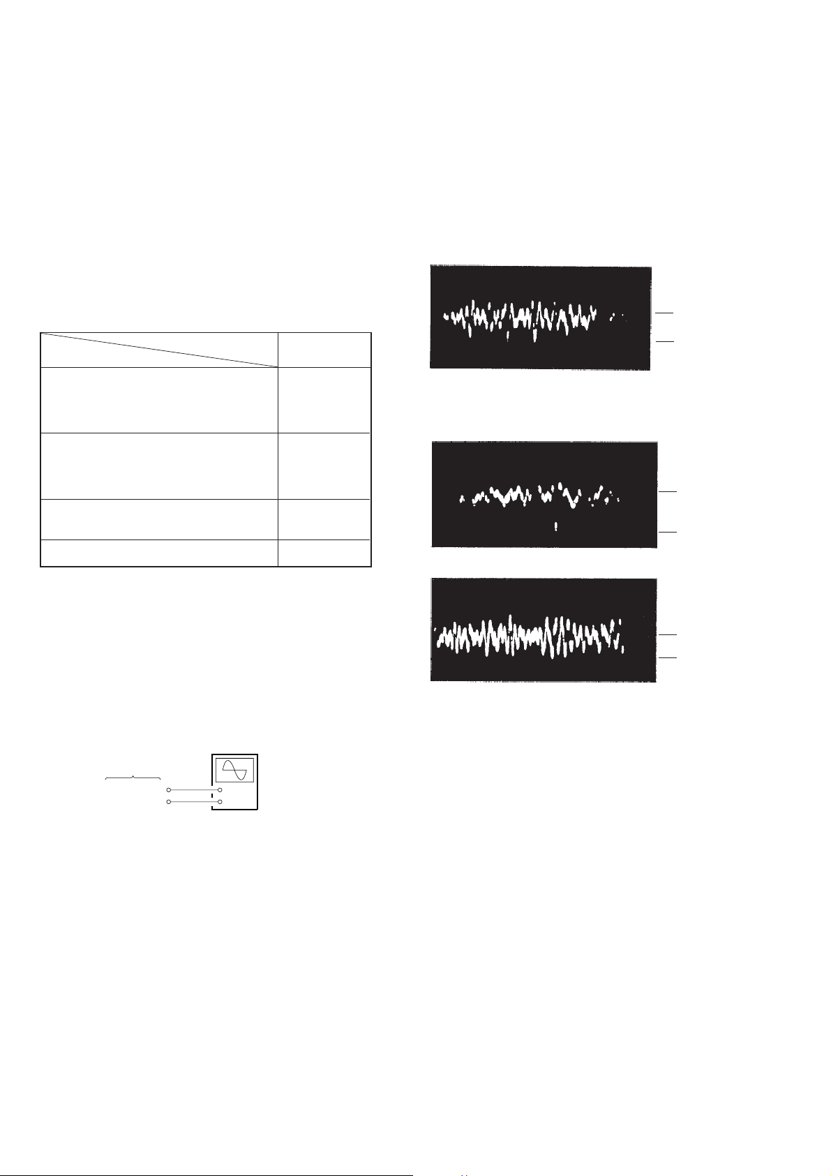
Focus Gain Adjustment
A frequency response analyzer is necessary in order to perform
this adjustment exactly.
However, this gain has a margin, so even if it is slightly off, there
is no problem. Therefore, do not perform this adjustment.
Focus gain determines the pick-up follow-up (vertical and horizontal) relative to mechanical noise and mechanical shock when
the 2-axis device operate.
However , as these reciprocate, the adjustment is at the point where
both are satisfied.
• When gain is raised, the noise when the 2-axis device operates
increases.
• When gain is lowered, mechanical shock and skipping occurs
more easily.
• When gain adjustment is off, the symptoms below appear.
Procedure:
1. Keep the set horizontal.
If the set is not horizontal, this adjustment cannot be per-
(
formed due to the gravity against the 2-axis device.
2. Insert the disc (YEDS-18) and press ^ button.
3. Connect the oscilloscope TP (FE) and TP (VREF) on MAIN
board.
4. Adjustment RV502 on MAIN board so that the waveform is
as shown in the figure below.
VOLT/DIV: 100 mV
TIME/DIV: 2 mS
100 mV
)
Symptoms
• The time until music starts becomes longer for
STOP → PLAY or automatic selection.
(=, + buttons pressed.)
(Normally takes about 2 seconds.)
• Music does not start and disc continues to
rotate for STOP → PLAY or automatic
selection.
(=, + buttons pressed.)
• Sound is interrupted during PLAY.
Or time counter display stops progressing.
• More noise during 2-axis device operation
Gain Focus
low
–
–
high
The following is a simple adjustment method.
– Primary Adjustment –
Note: Since exact adjustment cannot be performed, remember the posi-
tions of the controls before performing the adjustment. If the positions after the primary adjustment are only a little different, return
the controls to the original position.
Connection:
oscilloscope
MAIN board
TP (FE)
TP (VREF)
+
–
0 V
• Incorrect Examples (DC level changes more than on adjusted
waveform)
low focus gain
high focus gain
VOLT/DIV: 100 mV
TIME/DIV: 2 mS
200 mV
0 V
VOLT/DIV: 100 mV
TIME/DIV: 2 mS
75 mV
0 V
– 12 –
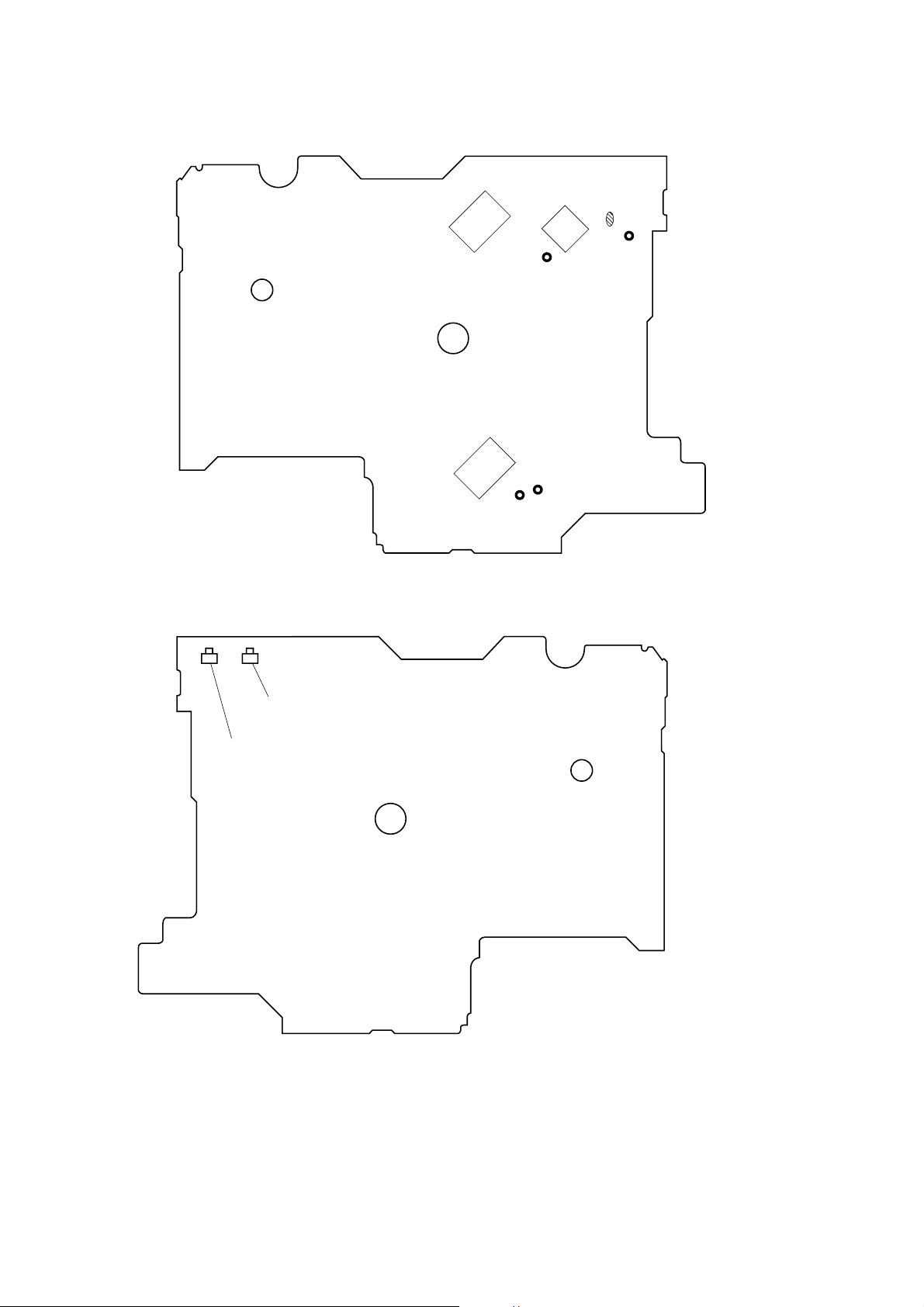
Adjustment Location:
[MAIN Board] (Conductor Side)
IC502
IC401
TP
(GND)
IC501
TP (RF)
TP (TEST)
TP
(FE)
TP
(VREF)
[MAIN Board] (Component Side)
RV502
Focus Gain Adjustment
RV501
Focus Bias Adjustment
– 13 –
 Loading...