

Sony ICFCA-2 Service manual
ICF-CA2
SERVICE MANUAL
Ver 1.0 2000. 04
SPECIFICATIONS
Frequency range
FM : 76 – 108 MHz
AM : 530 – 1,710 kHz
E Model
Speaker
Approx. 5.7 cm (21/4 in.) dia. 8 Ω
Power output
100 mW
Power requirements
Radio : 1.5 V DC battery (R6) × 2
Clock : 1.5 V DC battery (R6) × 1
Power Auto Off function
Approx. 80 minutes
Dimensions
Approx. 94 × 97 × 87 mm (w/h/d)
(31/4 × 31/7 × 31/2 in) incl. projecting parts and controls
Mass
Approx. 390 g (14 oz.) incl. batteries
Desighn and specifications are subject to change without notice.
FM/AM CLOCK RADIO
TABLE OF CONTENTS
1. GENERAL ·········································································· 2
2. DISASSEMBLY
2-1. CABINET (REAR) AND CLOCK ···································· 3
2-2. KNOB (TUN) (BAND) (VR)············································· 4
2-3. MAIN BOARD ·································································· 4
3. ADJUSTMENT ································································· 6
4. DIAGRAM
4-1. IC Block Diagram ······························································ 7
4-2. Printed Wiring Board·························································· 8
4-3. Schematic Diagram ···························································· 9
5. EXPLODED VIEWS ······················································ 11
6. ELECTRICAL PARTS LIST·······································12
SECTION 1
GENERAL
This section is extracted
from instruction manual.
Notes on chip component replacement
• Never reuse a disconnected chip component.
• Notice that the minus side of a tantalum capacitor may be
damaged by heat.
Flexible Circuit Board Repairing
• Keep the temperature of soldering iron around 270˚C
during repairing.
• Do not touch the soldering iron on the same conductor of the
circuit board (within 3 times).
• Be careful not to apply force on the conductor when soldering
or unsoldering.
— 2 —
SECTION 2
d
k
DISASSEMBLY
• The equipment can be removed using the following procedure.
Cabinet (rear) and clockSet
knob (tun) (band) (vr)
Main boar
Note : Follow the disassembly procedure in the numerical order given.
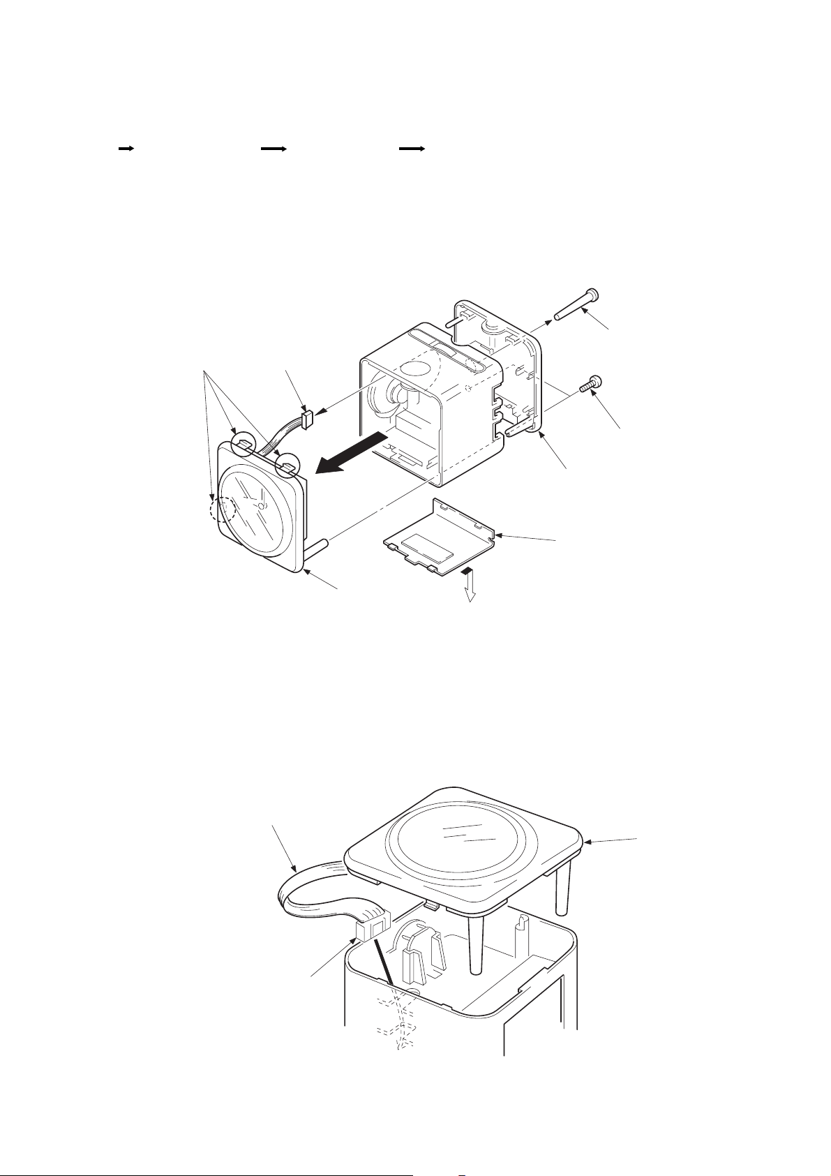
2-1. CABINET (REAR) AND CLOCK
6
CN1 (6P) Claws
5
2
Knob (TIME SET)
3
(P3 x 16)
4
Cabinet (rear)
1
Lid, battery case
Two screws
7
Clock
(It has a claw)
• NOTE ON INSTALLING CONNECTION CORD
Connection cord
To Main board
CN1.
Cloc
— 3 —
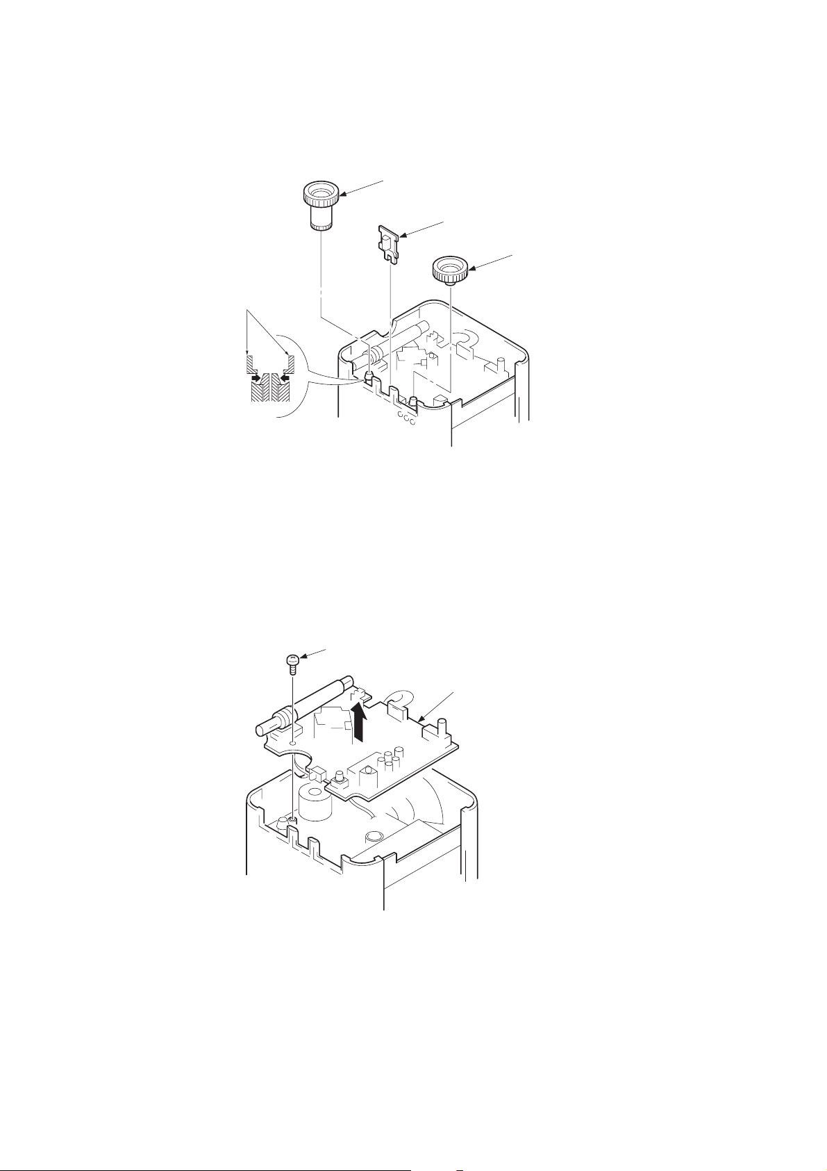
2-2. KNOB (TUN) (BAND) (VR)
)
d
Knob (TUN)
1
Knob (TUN)
2
Knob (BAND)
3
Knob (VR
2-3. MAIN BOARD
1
Screw (M2.6 x 5)
2
Main boar
— 4 —
 Loading...