

Sony ICFC-773 Service manual
ICF-C773/C773L
SERVICE MANUAL
Ver. 1.0 2005.04
Photo : ICF-C773L
SPECIFICATIONS
Time display
UK, North and South America 12-hour system
Other countries/regions 24-hour system
Frequency range
Model for North and South America
Band ICF-C773 Channel step
FM 87.5 - 108 MHz 0.1 MHz
AM 530 - 1710 kHz 10 kHz
US Model
Canadian Model
ICF-C773
AEP Model
ICF-C773/C773L
UK Model
ICF-C773L
Model for other countries/regions
Band ICF-C773 ICF-C773L Channel step
FM 87.5 - 108 MHz 87.5 - 108 MHz 0.05 MHz
AM (MW) 531 - 1602 kHz 531 - 1602 kHz 9 kHz
LW — 153 - 279 kHz 3 kHz
Speaker
Approx. 4.5 cm (1 13/16 inches) dia. 8 Ω
Power output
150 mW (at 10 % harmonic distortion)
Power requirements
North and South American model: 120 V AC, 60 Hz
Other model: 230 V AC, 50 Hz
Dimensions
Approx. 90 × 169.5 × 94 mm (w/h/d)
(3 5/8 × 6 3/4 × 3 3/4 inches) including projecting parts and
controls
Mass
Approx. 640 g (1 lb 6.6 oz)
Approx. 710 g (1 lb 9.1 oz): ICF-C773L (UK model)
Design and specifications are subject to change without notice.
FM/AM PLL SYNTHESIZED CLOCK RADIO
FM/MW/LW PLL SYNTHESIZED CLOCK RADIO
ICF-773
ICF-773L
9-879-611-01
2005D02-1
© 2005.04
Sony Corporation
Personal Audio Group
Published by Sony Engineering Corporation
ICF-C773/C773L
TABLE OF CONTENTS
Specifications ............................................................................ 1
1. GENERAL
Location and Function of Controls .................................. 3
2. DISASSEMBLY
2-1. Disassembly Flow .................................................. 4
2-2 Cabinet (Lower). .................................................... 4
2-3. Power Board ........................................................... 5
2-4. Foot Sub Assy ........................................................ 5
2-5. Cabinet (Rear) Sub Assy ........................................ 6
2-6. Side Panel (L), Side Panel (R) ............................... 6
2-7. Cabinet (Front) Sub Assy ....................................... 7
2-8. Reflector (L), Reflector (R) ................................... 7
2-9. LCD Board ............................................................. 8
3-10. Main Board ............................................................ 8
3. ELECTRICAL ADJUSTMENTS ............................... 9
4. DIAGRAMS
4-1. Printed Wiring Board – Main section – .................. 11
4-2. Schematic Diagram
– Main Board (US/CND, IT) (1/2) section– ........... 12
4-3. Schematic Diagram
– Main Board (US/CND, IT) (2/2) section– ........... 13
4-4. Schematic Diagram
– Main Board (AEP/UK) (1/2) section– ................. 14
4-5. Schematic Diagram
– Main Board (AEP/UK) (2/2) section– ................. 15
4-6. Printed Wiring Board – Key, LCD Board section –16
4-7. Schematic Diagram – Key, LCD Board section– .. 17
4-8. Printed Wiring Board – Power Board – ................. 18
4-9. Schematic Diagram – Power Board – .................... 19
4-10. Circuit Board Location ........................................... 20
4-11. IC Pin Function Descriptions ................................. 22
SAFETY CHECK-OUT
After correcting the original service problem, perform the following
safety checks before releasing the set to the customer:
Check the antenna terminals, metal trim, “metallized” knobs, screws,
and all other exposed metal parts for AC leakage. Check leakage as
described below.
LEAKAGE
The AC leakage from any exposed metal part to earth Ground and
from all exposed metal parts to any exposed metal part having a
return to chassis, must not exceed 0.5 mA (500 microampers).
Leakage current can be measured by any one of three methods.
1. A commercial leakage tester, such as the Simpson 229 or RCA
WT-540A. Follow the manufacturers’ instructions to use these
instruments.
2. A battery-operated AC milliammeter. The Data Precision 245
digital multimeter is suitable for this job.
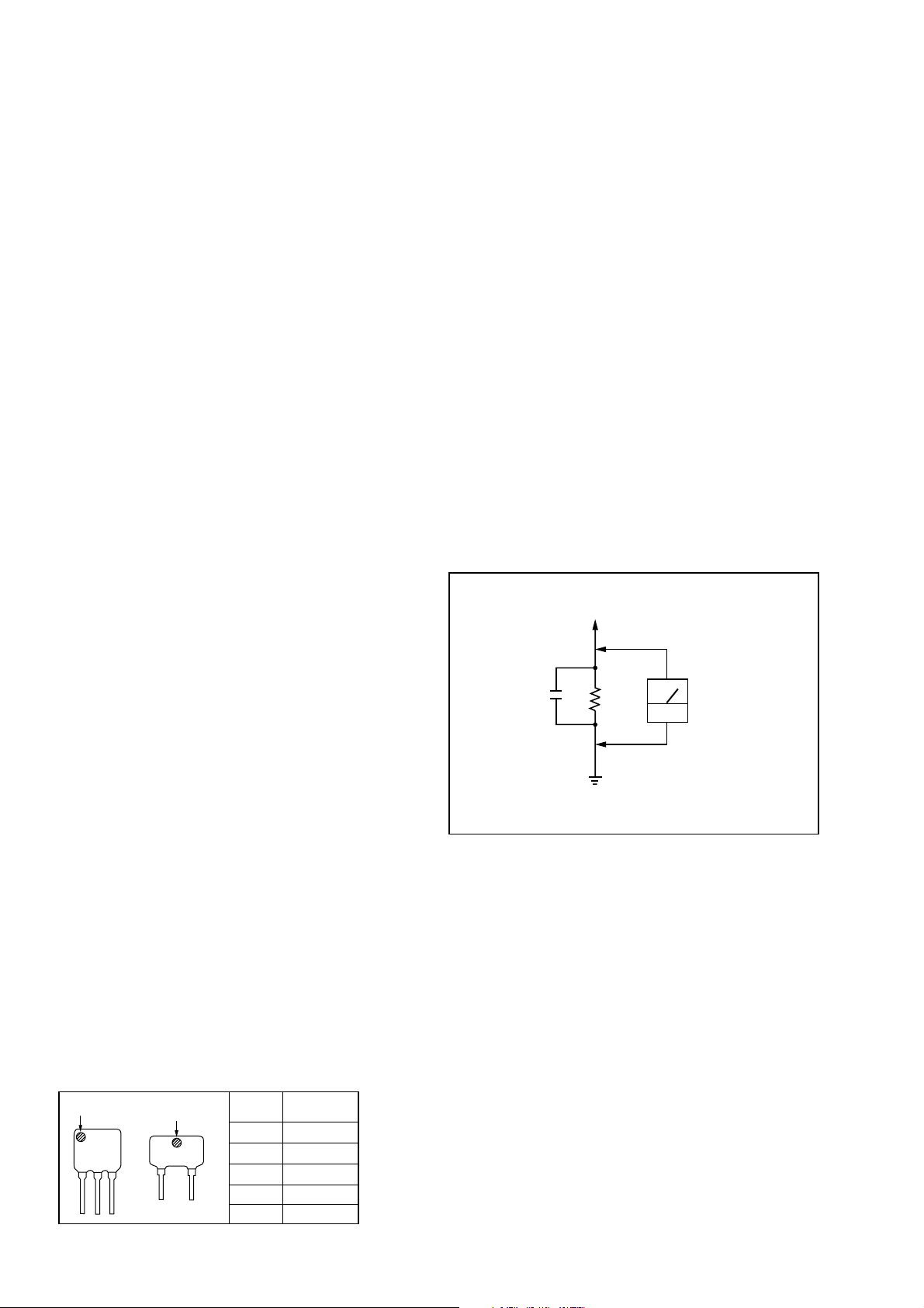
3. Measuring the voltage drop across a resistor by means of a
VOM or battery-operated AC voltmeter. The “limit” indication
is 0.75 V, so analog meters must have an accurate low-voltage
scale. The Simpson 250 and Sanwa SH-63Trd are examples
of a passive VOM that is suitable. Nearly all battery operated
digital multimeters that have a 2V AC range are suitable. (See
Fig. A)
To Exposed Metal
Parts on Set
0.15µF
1.5kΩ
AC
voltmeter
(0.75V)
5. EXPLODED VIEW ..................................................... 23
6. ELECTRICAL PARTS LIST................................... 25
• HOW TO CHANGE THE CERAMIC FILTER
This model is used two ceramic filters of CF2 and CF3.
You must use same type of color marked ceramic filters in
order to meet same specifications.
Therefore, the ceramic filter must change two pieces together
since it's supply two pieces in package as a spare parts.
mark
CF2
mark
CF3
Mark
no mark
blue
orange
black
white
Center
frequency
10.70MHz
10.67MHz
10.73MHz
10.64MHz
10.76MHz
Earth Ground
Fig. A. Using an AC voltmeter to check AC leakage.
SAFETY-RELATED COMPONENT WARNING!!
COMPONENTS IDENTIFIED BY MARK 0 OR DOTTED LINE WITH
MARK 0 ON THE SCHEMATIC DIAGRAMS AND IN THE PARTS
LIST ARE CRITICAL TO SAFE OPERATION.
REPLACE THESE COMPONENTS WITH SONY PARTS WHOSE
PA RT NUMBERS APPEAR AS SHOWN IN THIS MANUAL OR IN
SUPPLEMENTS PUBLISHED BY SONY.
ATTENTION AU COMPOSANT AYANT RAPPORT
À LA SÉCURITÉ!!
LES COMPOSANTS IDENTIFIÉS PAR UNE MARQUE 0 SUR LES
DIAGRAMMES SCHÉMATIQUES ET LA LISTE DES PIÈCES
SONT CRITIQUES POUR LA SÉCURITÉ DE FONCTIONNEMENT.
NE REMPLACER CES COMPOSANTS QUE PAR DES PIÈCES
SONY DONT LES NUMÉROS SONT DONNÉS DANS CE MANUEL
OU DANS LES SUPPLÉMENTS PUBLIÉS PAR SONY.
2
Unleaded solder
Boards requiring use of unleaded solder are printed with the lead
free mark (LF) indicating the solder contains no lead.
(Caution: Some printed circuit boards may not come printed with
the lead free mark due to their particular size.)
: LEAD FREE MARK
Unleaded solder has the following characteristics.
•Unleaded solder melts at a temperature about 40°C higher than
ordinary solder.
Ordinary soldering irons can be used but the iron tip has to be
applied to the solder joint for a slightly longer time.
Soldering irons using a temperature regulator should be set to
about 350°C.
Caution: The printed pattern (copper foil) may peel away if
the heated tip is applied for too long, so be careful!
• Strong viscosity
Unleaded solder is more viscous (sticky, less prone to flow)
than ordinary solder so use caution not to let solder bridges
occur such as on IC pins, etc.
• Usable with ordinary solder
It is best to use only unleaded solder but unleaded solder may
also be added to ordinary solder.
ICF-C773/C773L
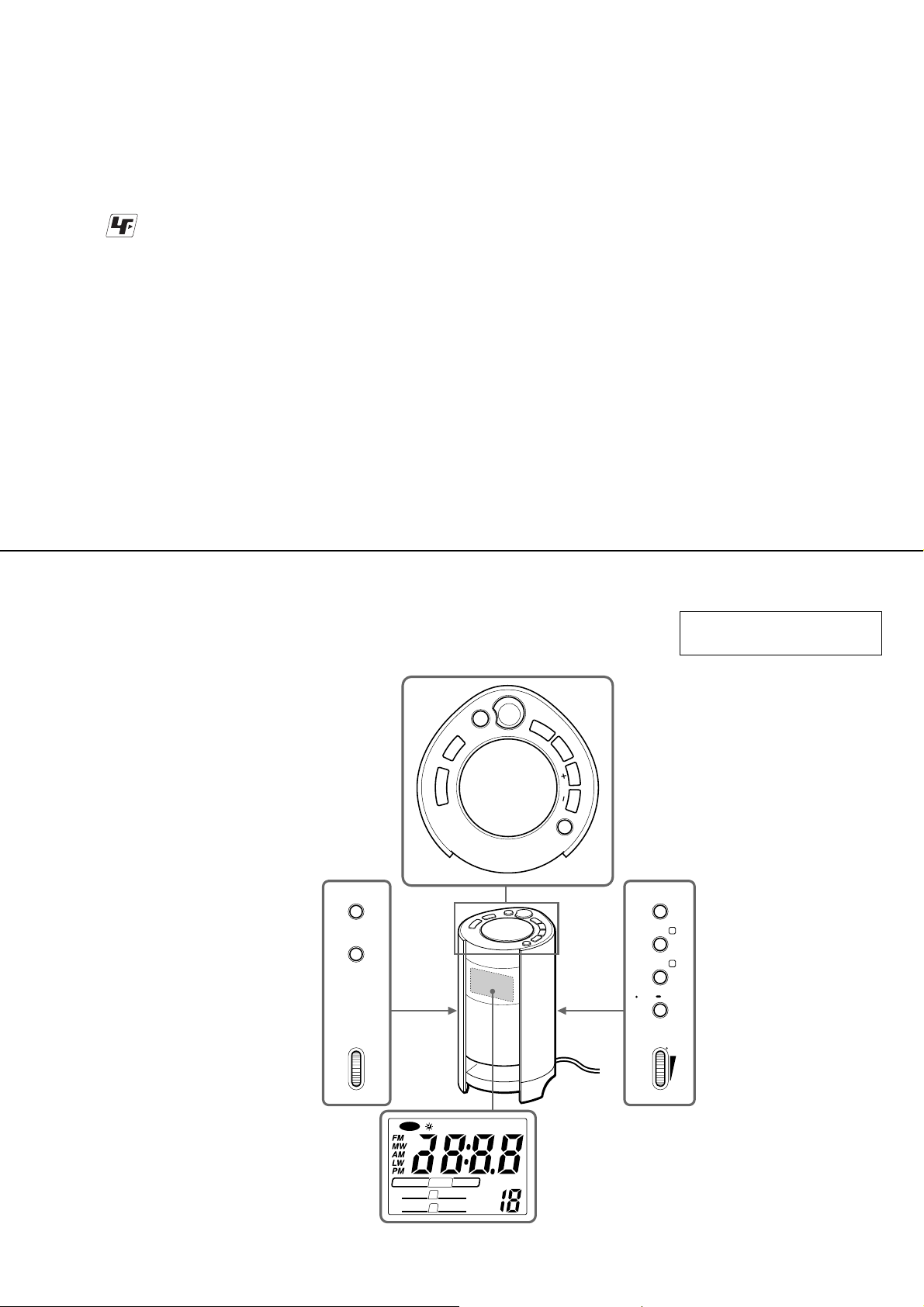
LOCATION AND FUNCTION OF CONTROLS
LIGHT
STANDBY
BRIGHTNESS
LIGHT
CONTROL
HIGH
SECTION 1
GENERAL
BAND
RADIO
RADIO
OFF
ON
P
E
E
L
S
T
H
G
I
L
F
F
O
/
N
O
T
H
G
I
L
ALARM
RESET
This section is extracted from
instruction manual.
N
A
P
S
L
E
E
P
T
U
N
E
/
T
I
M
E
S
E
T
R
E
T
N
E
E
D
O
M
E
N
U
T
ALARM MODE
ALARM A
ALARM B
D.T.S./ CLOCK
VOLUME
*
LOW
AC power cord
NAP
RADIO
SLEEP
STANDBY
RADIO
RADIO
LIGHT SLEEP
A
B
SOUND
SOUND
MHzkHz
WAKE UP
PRESET
* There is a tactile dot beside VOLUME to show the direction to turn up the volume.
3
ICF-C773/C773L
)
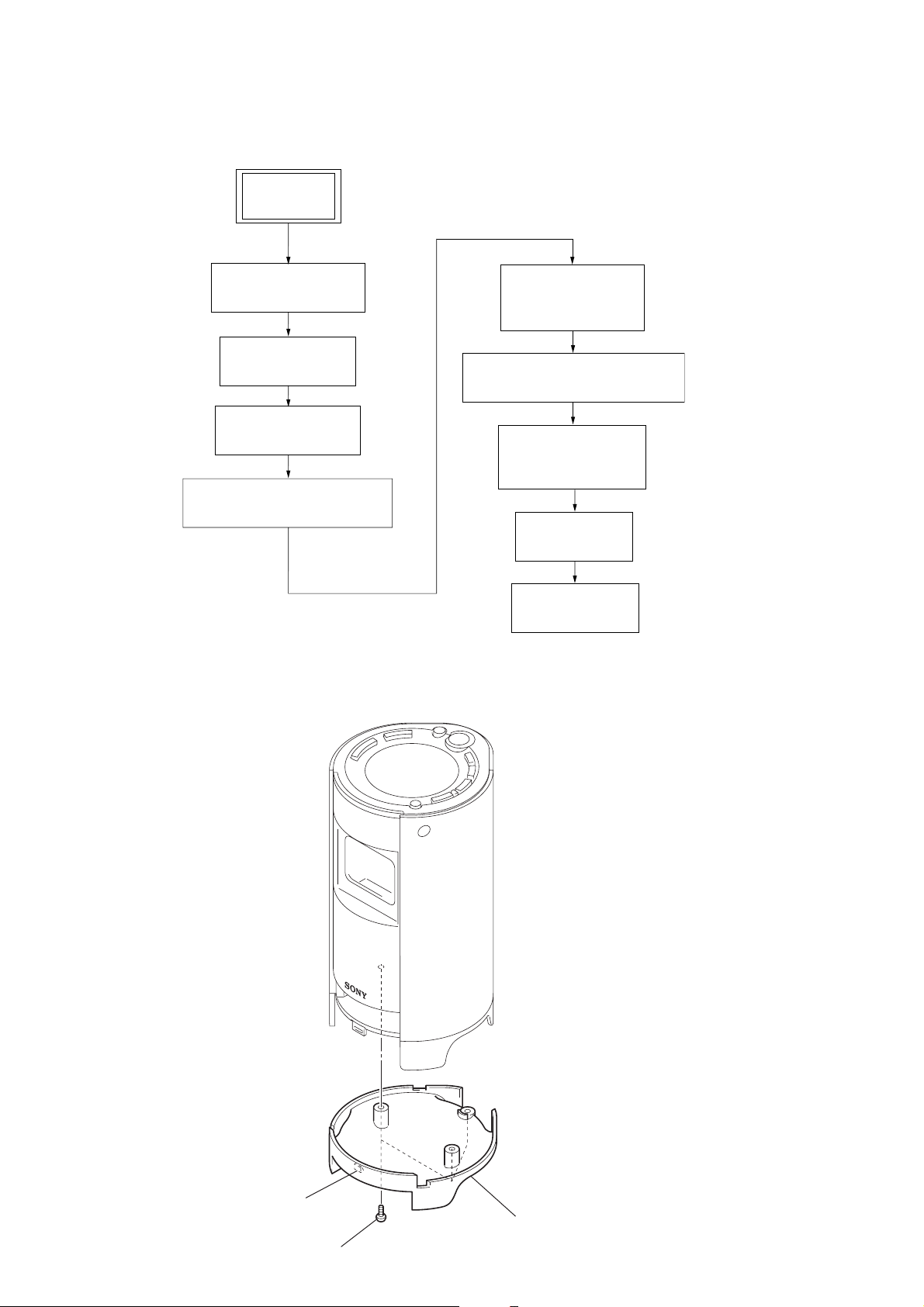
• This set can be disassembled in the order shown below.
2-1. DISASSEMBLY FLOW
SET
SECTION 2
DISASSEMBLY
2-2. CABINET (LOWER)
(Page 4)
2-3. POWER BOARD
(Page 5)
2-4. FOOT SUB ASSY
(Page 5)
2-5. CABINET (REAR) SUB ASSY
(Page 6)
Note: Follow the disassembly procedure in the numerical order given.
2-2. CABINET (LOWER)
2-6. SIDE PANEL (L),
SIDE PANEL (R)
(Page 6)
2-7. CABINET (FRONT) SUB ASSY
(Page 7)
2-8. REFLECTOR (L),
REFLECTOR (R)
(Page 7)
2-9. LCD BOARD
(Page 8)
2-10. MAIN BOARD
(Page 8)
2
claw
3
cabinet (lower
1
three screws (B2.6)
4
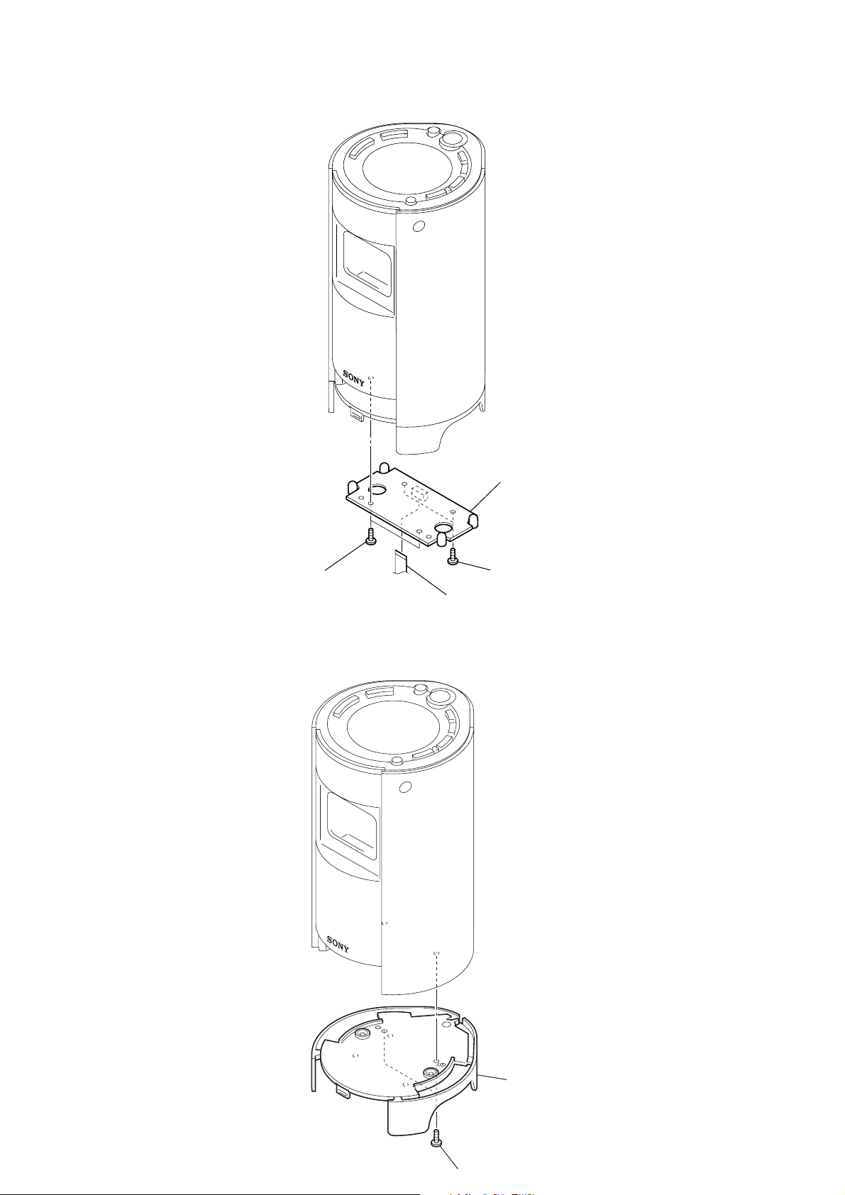
2-3. POWER BOARD
ICF-C773/C773L
2-4. FOOT SUB ASSY
2
two screws
4
3
two screws
1
flat wire (CN401)
POWER board
1
two screws
2
foot sub assy
5
ICF-C773/C773L
y
e
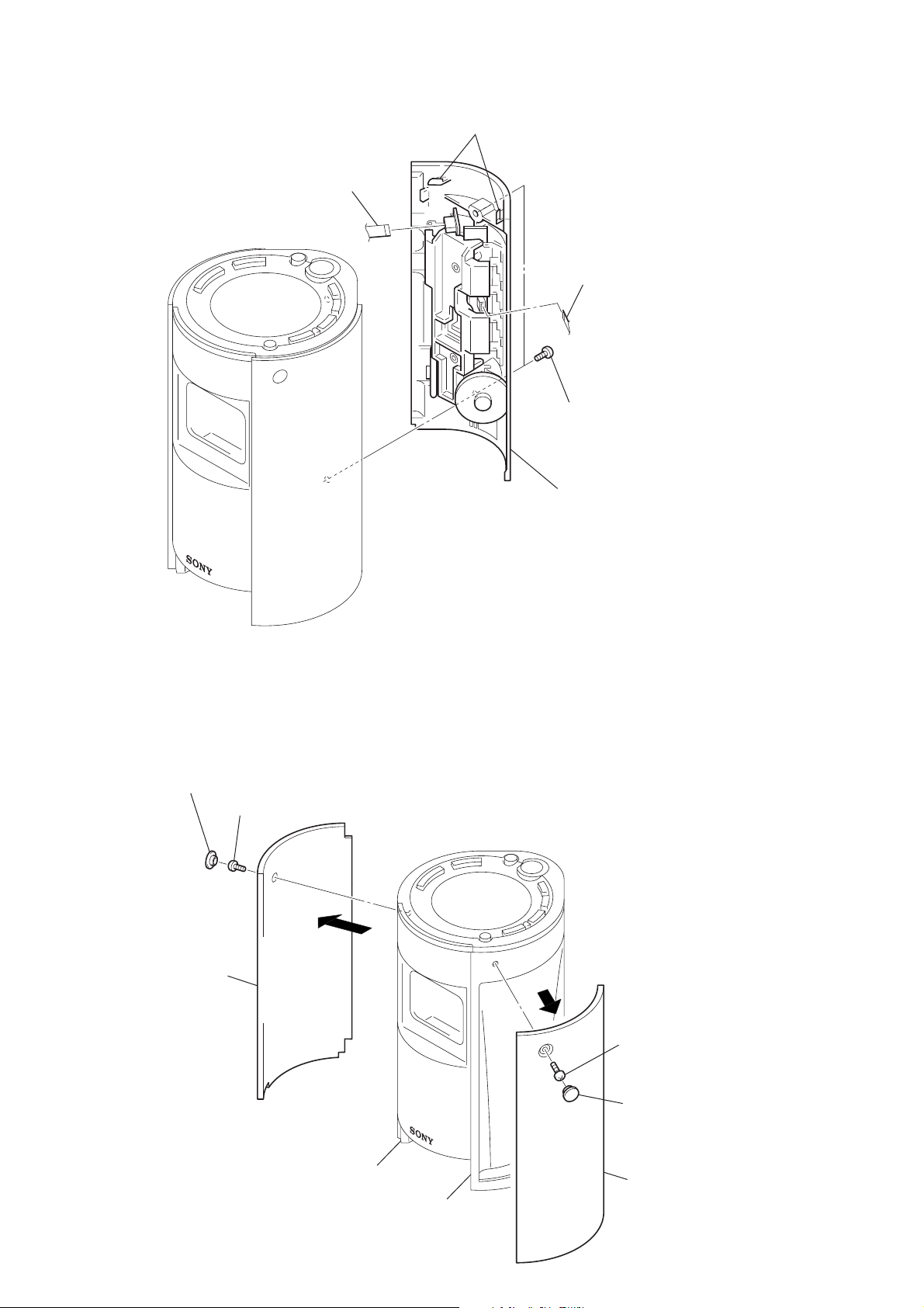
2-5. CABINET (REAR) SUB ASSY
4
flat wire (CN302)
2
two claws
5
flat wire (CN301)
1
two screws
(B2.6)
3
cabinet (rear) sub ass
2-6. SIDE PANEL (L), SIDE PANEL (R)
Note : Please do not damage side panels when side panels
are remove from reflectors. (
5
ornament plate
6
screw
(BV2.6)
8
side panel (L)
7
3, 7
)
3
2
screw
(BV2.6)
1
ornament plat
reflector (L)
reflector (R)
4
side panel (R)
6
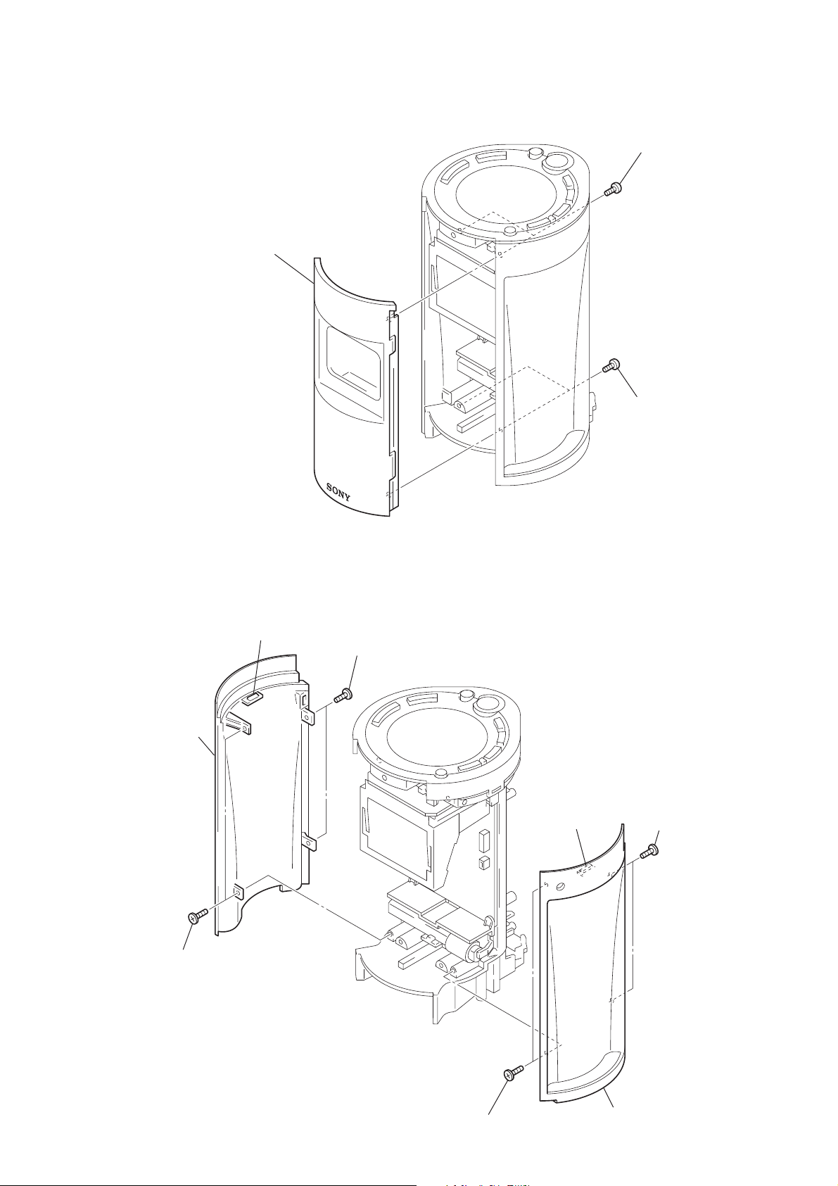
2-7. CABINET (FRONT) SUB ASSY
3
cabinet (front) sub assy
ICF-C773/C773L
1
two screws
(B2.6)
2
two screws
(B2.6)
2-8. REFLECTOR (L), REFLECTOR (R)
7
claw
8
reflector (R)
5
two screws
6
two screws
3
claw
2
two screws
1
two screws
4
reflector (L)
7
ICF-C773/C773L
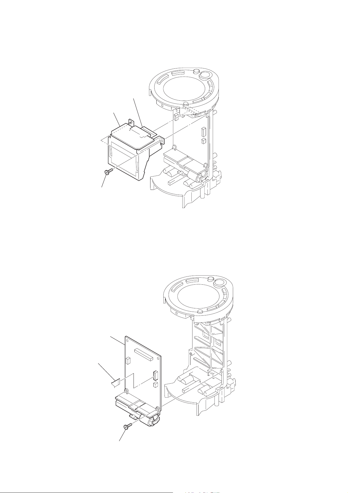
2-9. LCD BOARD
2
flat wire (CN102)
3
LCD board
2-10. MAIN BOARD
1
(1.7)
3
MAIN board
two screws
1
flat wire (CN104)
2
two screws
(1.7)
8
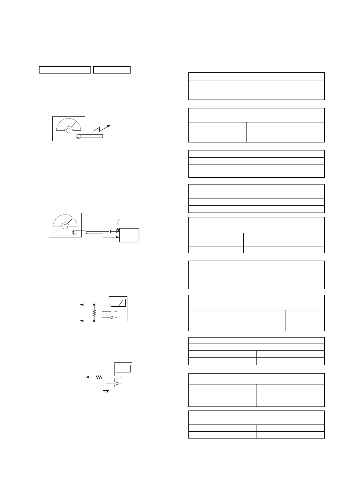
TUNER SECTION 0 dB = 1 µV
)
• AM Section
Setting:
BAND button: AM <MW and LW>
SECTION 3
ELECTRICAL ADJUSTMENTS
< > : ICF-C773L
• ICF-C773 [ ] : 9kHz step
Adjust for a maximum reading on level meter.
ICF-C773/C773L
AM IF ADJUSTMENT
T1
450 kHz
AM RF signal
generator
Put the lead-wire
antenna close to
the set.
30% amplitude
modulation by
400 Hz signal
• FM Section
Setting:
BAND button:FM
FM RF signal
generator
TP1 (ANT
0.01
µ
F
set
22.5 kHz frequency
deviation by 400 Hz signal
output level : as low as possible
• Connecting Level Meter (FM, AM<MW and LW>)
level meter
(range 0.5-5V AC)
32
SP+
SP–
Ω
AM FREQUENCY COVERAGE
ADJUSTMENT
Frequency Display
Reading on Digital voltmeter 2.9 ± 0.1 V
Adjustment Part L3 <confirmation>
Adjust for a maximum reading on level meter.
L4-1 CT2
580 kHz [621kHz] 1.490 kHz [1.404kHz]
530 kHz [531 kHz]
AM TRACKING ADJUSTMENT
1,710 kHz
9.5 ± 1.0V[9.4 ± 0.1V]
[1,602 kHz]
• ICF-C773L
MW IF ADJUSTMENT
Adjust for a maximum reading on level meter.
T1
450 kHz
MW FREQUENCY COVERAGE
ADJUSTMENT
Frequency Display 531 kHz 1.602 kHz
Reading on Digital voltmeter
Adjustment Part L3 <confirmation>
Adjust for a maximum reading on level meter.
L4-1 CT2
621 kHz 1.404 kHz
LW FREQUENCY COVERAGE
Frequency Display 153 kHz 279 kHz
Reading on Digital voltmeter 2.4 ± 0.3 V 9.0 ± 0.1 V
Adjustment Part <confirmation> CT4
2.75 ± 0.1 V 9.4 ± 1.0 V
MW TRACKING ADJUSTMENT
ADJUSTMENT
• Connecting Digital Voltmeter (FM, AM <MW and LW>)
digital
voltmeter
100 kΩ
TP8 (VT)
• Repeat the procedures in each adjustment several times, and the
frequency coverage and tracking adjustments should be finally
done by the trimmer capacitors.
LW TRACKING ADJUSTMENT
Adjust for a maximum reading on level meter.
L4-2 CT3
162 kHz 243 kHz
• ICF-C773/C773L
FM FREQUENCY COVERAGE
CONFIRMATION
Frequency Display 87.5 MHz 108 MHz
Reading on Digital voltmeter 3.1 ± 0.3 V 9.0 ± 1.0 V
Adjustment Part <confirmation> <confirmation>
FM TRACKING ADJUSTMENT
Adjust for a maximum reading on level meter.
L1 CT1
87.5 MHz 108 MHz
Adjustment and Connect Location: See page 10.
9
 Loading...