

Sony ICF-C610 Service manual
ICF-C160
SERVICE MANUAL
SPECIFICATIONS FEATURES
Frequency range
FM: 87.5–108 MHz
AM: 526.5–1606.5kHz (Italian)
530–1605 kHz (EXCEPT Italian)
Speaker
Approx. 6.6 cm (25/8 inches) dia. 8 ohms
Power output
120 mW (at 10% harmonic distortion)
Power requirements
120 V AC, 60 Hz
For power backup: 9 V DC, one 6F22 battery
Battery life
Approx. 35 hours using the Sony S-006 P (U)
battery
Dimensions
Approx. 120 124 132 mm (w/h/d)
(43/4 × 5 × 51/4 inches) incl. projecting parts
and controls
Mass
Approx. 660 g (1 Ib 7.2 oz) not incl. battery
US Model
Canadian Model
AEP Model
E Model
Australian Model
• Dual alarm
• Date display
• Full power backup function to keep the clock, the
alarm (radio and buzzer) and the radio operation
during a power interruption with a 6F22 battery
(not supplied) installed.
Design and specifications are subject to change
without notice.
MICROFILM
FM/AM CLOCK RADIO
r
SECTION 1
SERVICING NOTE
SAFETY CHECK-OUT
After correcting the original service problem, perform the following safety check before releasing the set to the customer:
Check the antenna terminals, metal trim, “metallized” knobs,
screws, and all other exposed metal parts for AC leakage. Check
leakage as described below.
LEAKAGE TEST
The AC leakage from any exposed metal part to earth ground and
from all exposed metal parts to any exposed metal part having a
return to chassis, must not exceed 0.5 mA (500 microampers).
Leakage current can be measured by any one of three methods.
1. A commercial leakage tester, such as the Simpson 229 or RCA
WT -540A. Follow the manuf acturers’ instructions to use these
instruments.
2. A battery-operated A C milliammeter. The Data Precision 245
digital multimeter is suitable for this job.
3. Measuring the voltage drop across a resistor by means of a
VOM or battery-operated AC voltmeter. The “limit” indication is 0.75 V, so analog meters must have an accurate lowvoltage scale. The Simpson 250 and Sanwa SH-63T rd are examples of a passive VOM that is suitable. Nearly all battery
operated digital multimeters that have a 2 V AC range are
suitable. (See Fig. A)
To Exposed Metal
Parts on Set
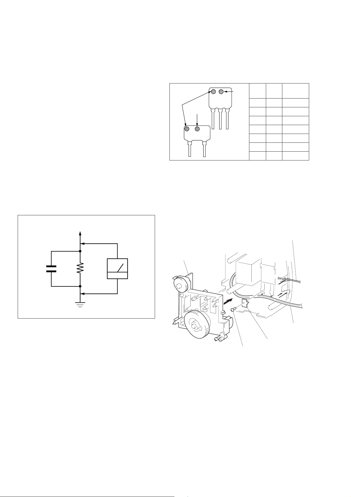
HOW TO CHANGE THE FM CERAMIC FILTERS
This model is used two ceramic filters of CF1 and CF3.
You must use same type of color marked ceramic filters in order
to meet same specifications.
Therefore, the ceramic filter must change two pieces together since
it's supply two pieces in one package as a spare parts.
Center
frequency
mark 1
mark 2
CF1
mark 2
Mark 1 Mark 2
CF3
red — 10.70MHz
blue — 10.67MHz
orange — 10.73MHz
black — 10.64MHz
white — 10.76MHz
white white 10.75 MHz
yellow — 10.79 MHz
CORD DRESSING
(POWER, ANTENNA)
1) Connect the power cord and antenna cord as shown in the
figure.
2) Mount the cord stopper with screws (P3 × 10).
Note:Tighten completely the screws (P3 × 10).
AC
0.15 µF
1.5 k
Ω
Earth Ground
voltmete
(0.75 V)
Fig. A. Using an AC voltmeter to check AC leakage.
Note on chip component replacement
• Never reuse a disconnected chip component.
• Notice that the minus side of a tantalum capacitor may be dam-
aged by heat.
antenna cord
chassis
power cord
cord stopper
screw
(P3 × 10)
SAFETY-RELATED COMPONENT WARNING!!
COMPONENTS IDENTIFIED BY MARK ! OR DOTTED
LINE WITH MARK ! ON THE SCHEMATIC DIAGRAMS
AND IN THE PARTS LIST ARE CRITICAL TO SAFE
OPERATION. REPLACE THESE COMPONENTS WITH
SONY PARTS WHOSE PART NUMBERS APPEAR AS
SHOWN IN THIS MANU AL OR IN SUPPLEMENTS PUBLISHED BY SONY.
ATTENTION AU COMPOSANT AYANT RAPPORT
À LA SÉCURITÉ!
LES COMPOSANTS IDENTIFIÉS P AR UNE MARQUE !
SUR LES DIAGRAMMES SCHÉMATIQUES ET LA LISTE
DES PIÈCES SONT CRITIQUES POUR LA SÉCURITÉ
DE FONCTIONNEMENT. NE REMPLACER CES COMPOSANTS QUE PAR DES PIÈCES SONY DONT LES
NUMÉROS SONT DONNÉS DANS CE MANUEL OU
DANS LES SUPPLÉMENTS PUBLIÉS PAR SONY.
– 2 –
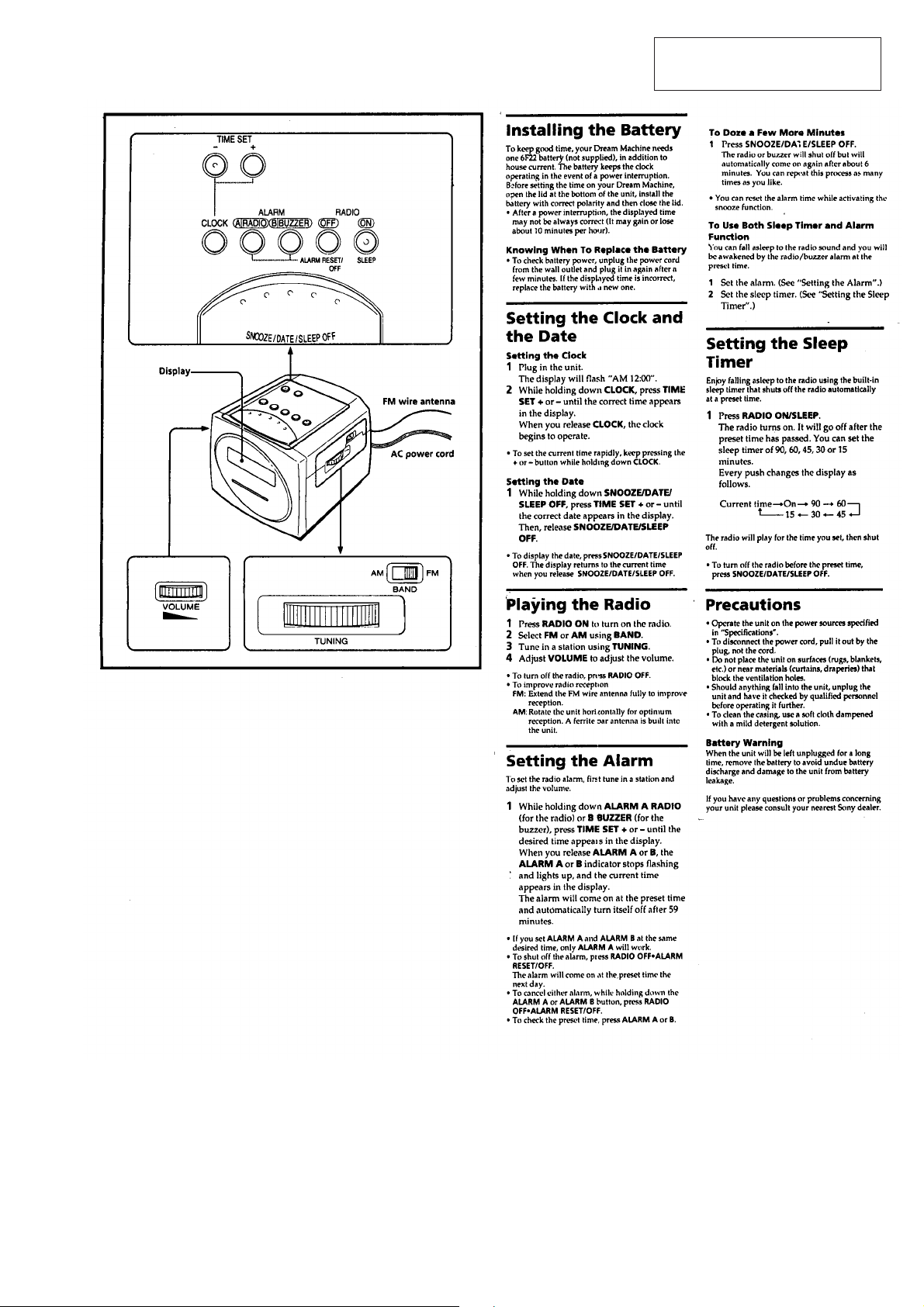
SECTION 2
GENERAL
This section is extracted from
instruction manual.
– 3 –
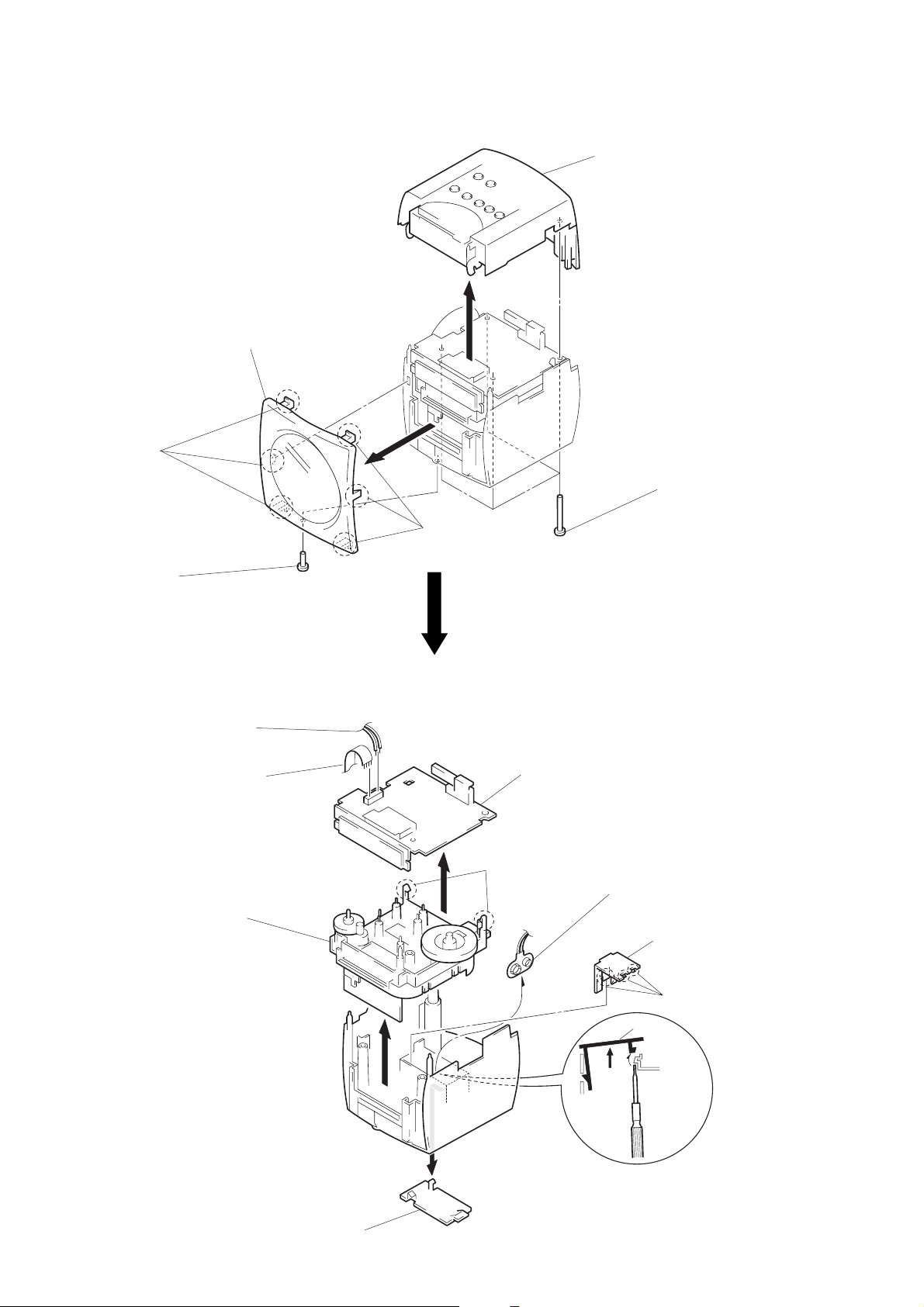
SECTION 3
DISASSEMBLY
Note: Follow the disassembly procedure in the numerical order given.
FRONT PANEL ASS’Y
4
three claws
2
screw
(P3 × 10)
5
front panel ass’y
4
three claws
3
cabinet (upper)
1
four screws
(P3 × 35)
MAIN BOARD, CHASSIS
5
speaker cord
6
cord (4 core)
9
chassis
7
two claws
8
radio board
4
battery snap
cover
3
cover
2
three claws
1
battery case lid
– 4 –
 Loading...