

Sony HT-SF370 User Manual

Home Theatre
System
4-168-166-11(1)
Operating Instructions
HT-SF370
HT-SS370
©2010 Sony Corporation
WARNING
To reduce the risk of fire or electric
shock, do not expose this apparatus to
rain or moisture.
To reduce the risk of fire, do not cover the
ventilation opening of the apparatus with
newspapers, tablecloths, curtains, etc. Do not place
the naked flame sources such as lighted candles on
the apparatus.
Do not install the appliance in a confined space, such
as a bookcase or built-in cabinet.
To reduce the risk of fire or electric shock, do not
expose this apparatus to dripping or splashing, and
do not place objects filled with liquids, such as
vases, on the apparatus.
As the main plug is used to disconnect the unit from
the mains, connect the unit to an easily accessible
AC outlet. Should you notice an abnormality in the
unit, disconnect the main plug from the AC outlet
immediately.
Do not expose batteries or apparatus with batteryinstalled to excessive heat such as sunshine, fire or
the like.
The unit is not disconnected from the mains as long
as it is connected to the AC outlet, even if the unit
itself has been turned off.
To prevent injury, this apparatus must be securely
attached to the floor/wall in accordance with the
installation instructions.
For customers in the United
States and Canada
ENERGY STAR® is a U.S. registered
mark.
As an ENERGY STAR
Corporation has determined that this
product meets the ENERGY STAR
guidelines for energy efficiency.
®
partner, Sony
®
For customers in the United
States
Owner’s Record
The model and serial numbers are located on the rear
of the unit. Record these numbers in the space
provided below. Refer to them whenever you call
upon your Sony dealer regarding this product.
Model No.
This symbol is intended to alert the
user to the presence of uninsulated
“dangerous voltage” within the
product’s enclosure that may be of
sufficient magnitude to constitute a
risk of electric shock to persons.
This symbol is intended to alert the
user to the presence of important
operating and maintenance
(servicing) instructions in the
literature accompanying the
appliance.
Serial No.
Important Safety Instructions
1) Read these instructions.
2) Keep these instructions.
3) Heed all warnings.
4) Follow all instructions.
5) Do not use this apparatus near water.
6) Clean only with dry cloth.
7) Do not block any ventilation openings. Install in
accordance with the manufacturer’s instructions.
8) Do not install near any heat sources such as
radiators, heat registers, stoves, or other
apparatus (including amplifiers) that produce
heat.
9) Do not defeat the safety purpose of the polarized
or grounding-type plug. A polarized plug has
two blades with one wider than the other. A
grounding type plug has two blades and a third
grounding prong. The wide blade or the third
prong are provided for your safety. If the
provided plug does not fit into your outlet,
consult an electrician for replacement of the
obsolete outlet.
10)Protect the power cord from being walked on or
pinched particularly at plugs, convenience
receptacles, and the point where they exit from
the apparatus.
11)Only use attachments/accessories specified by
the manufacturer.
US
2

12)Use only with the cart, stand, tripod, bracket, or
table specified by the manufacturer, or sold with
the apparatus. When a cart is used, use caution
when moving the cart/apparatus combination to
avoid injury from tip-over.
13)Unplug this apparatus during lightning storms or
when unused for long periods of time.
14)Refer all servicing to qualified service personnel.
Servicing is required when the apparatus has
been damaged in any way, such as power-supply
cord or plug is damaged, liquid has been spilled
or objects have fallen into the apparatus, the
apparatus has been exposed to rain or moisture,
does not operate normally, or has been dropped.
The following FCC statement
applies only to the version of
this model manufactured for
sale in the U.S.A. Other
versions may not comply with
FCC technical regulations.
NOTE:
This equipment has been tested and found to comply
with the limits for a Class B digital device, pursuant
to Part 15 of the FCC Rules. These limits are
designed to provide reasonable protection against
harmful interference in a residential installation.
This equipment generates, uses and can radiate radio
frequency energy and, if not installed and used in
accordance with the instructions, may cause harmful
interference to radio communications. However,
there is no guarantee that interference will not occur
in a particular installation. If this equipment does
cause harmful interference to radio or television
reception, which can be determined by turning the
equipment off and on, the user is encouraged to try
to correct the interference by one or more of the
following measures:
– Reorient or relocate the receiving antenna.
– Increase the separation between the equipment
and receiver.
– Connect the equipment into an outlet on a circuit
different from that to which the receiver is
connected.
– Consult the dealer or an experienced radio/TV
technician for help.
CAUTION
You are cautioned that any changes or modifications
not expressly approved in this manual could void
your authority to operate this equipment.
US
3
About This Manual
• The instructions in this manual are for model
HT-SF370 and HT-SS370. In this manual, models
of area code CA2 is used for illustration purposes
unless stated otherwise. Any difference in
operation is clearly indicated in the text, for
example, “Models of area code U2 only”.
• The instructions in this manual describe the
controls on the supplied remote. You can also use
the controls on the receiver if they have the same
or similar names as those on the remote.
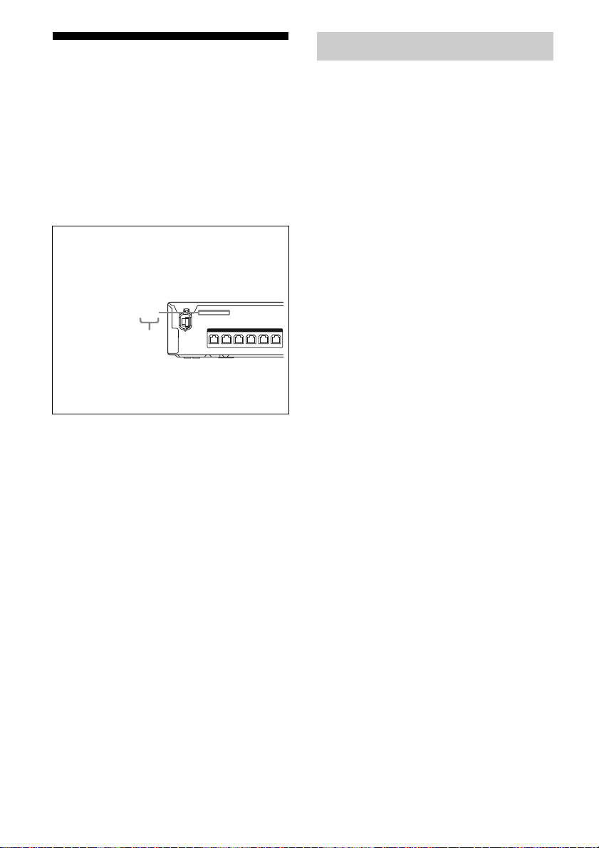
About area codes
The area code of the receiver you purchased is
shown on the upper left portion of the rear panel
(see the illustration below).
4-XXX-XXX-XX(X) AA
Area code
SPEAKERS
FRONT L SUR R SUR L CENTER
FRONT R
SUBWOOFER
On Copyrights
This receiver incorporates Dolby* Digital and Pro
Logic Surround and the DTS** Digital Surround
System.
* Manufactured under license from Dolby
Laboratories. Dolby, Pro Logic, and the doubleD symbol are trademarks of Dolby Laboratories.
** Manufactured under license under U.S. Patent
#’s: 5,451,942; 5,956,674; 5,974,380;
5,978,762; 6,487,535 & other U.S. and
worldwide patents issued & pending. DTS and
DTS Digital Surround are registered trademarks
and the DTS logos and Symbol are trademarks of
DTS, Inc. © 1996-2008 DTS, Inc. All Rights
Reserved.
This receiver incorporates High-Definition
Multimedia Interface (HDMI
HDMI, the HDMI logo and High-Definition
Multimedia Interface are trademarks or registered
trademarks of HDMI Licensing LLC.
TM
) technology.
Any differences in operation, according to the area
code, are clearly indicated in the text, for example,
“Models of area code AA only”.
“x.v.Color” and “x.v.Color” logo are trademarks of
Sony Corporation.
“BRAVIA” is a trademark of Sony Corporation.
“PLAYSTATION” is a trademark of Sony
Computer Entertainment Inc.
“S-AIR” and its logo are trademarks of Sony
Corporation.
US
4

Table of Contents
Unpacking ..................................................... 6
Description and location of parts .................. 8
Getting Started
1: Installing the speakers............................. 15
2: Connecting the speakers ......................... 18
3: Connecting the TV.................................. 19
4: Connecting the audio/video
components ............................................ 20
5: Connecting the antennas ......................... 24
6: Preparing the receiver ............................. 24
7: Calibrating the appropriate settings
automatically
(AUTO CALIBRATION) ...................... 25
Playback
Selecting a component ................................ 29
Enjoying sound/images from the
components connected to the receiver ... 30
Enjoying Surround Sound
Selecting the sound field ............................. 33
Enjoying the sound at low volume
(NIGHT MODE).................................... 34
Turning off the receiver with the TV
(System Power Off)................................43
Using the power saving function
(HDMI Pass Through)............................ 44
Enjoying the TV sound via an HDMI
connection (Audio Return Channel).......45
Enjoying optimum sound field for the
selected scene (Scene Select) .................46
Enjoying movies with the optimum
sound field (Theater Mode)....................46
S-AIR Operations
About S-AIR products.................................47
Setting up an S-AIR product .......................48
Enjoying the system’s sound in another
room .......................................................52
Stabilizing S-AIR reception ........................ 54
Changing the channel for better sound
transmission............................................ 55
Enjoying the S-AIR receiver while the
S-AIR main unit is in standby mode ...... 56
Advanced Settings
Changing the input button assignments.......57
Settings and adjustments using the
amplifier menu .......................................58
Tuner Operations
Listening to FM/AM radio.......................... 35
Presetting radio stations .............................. 37
“BRAVIA” Sync Features
What is “BRAVIA” Sync? .......................... 39
Preparing for the “BRAVIA” Sync ............. 39
Playing back components with one-touch
operation (One-Touch Play)................... 41
Enjoying the TV sound from the speakers
connected to the receiver
(System Audio Control) ......................... 41
Additional Information
Glossary.......................................................63
Precautions .................................................. 65
Troubleshooting...........................................67
Specifications .............................................. 72
Index............................................................ 75
5
US
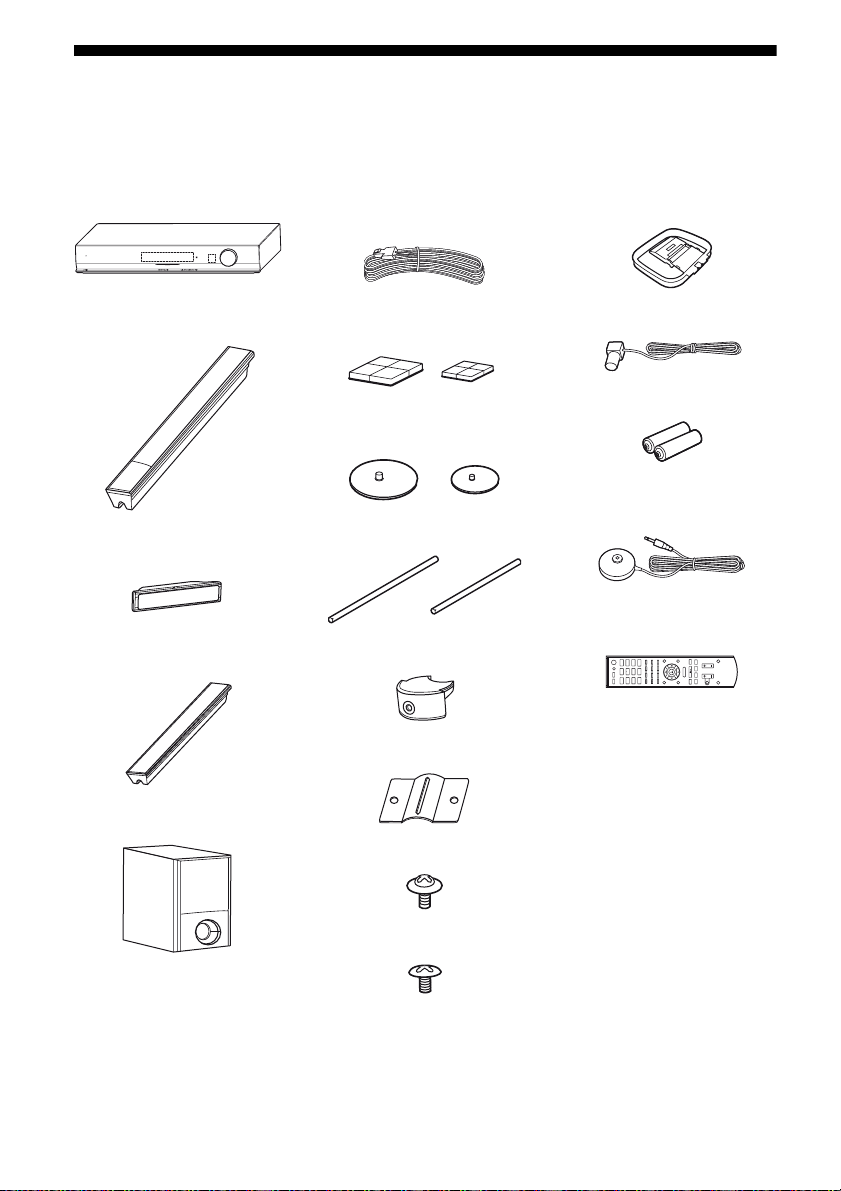
Unpacking
Be sure that you have the following items in your package.
HT-SF370 only
• Receiver (STR-KS370) (1)
POWER /
ACTIVE STANDBY
MASTER VOLUME
• Speaker cords (5, Red/
White/Grey/Blue/Green)
• AM loop antenna (1)
• Front speakers
(SS-MSP37F) (2)
•Center speaker
(SS-CNP37) (1)
• Surround speakers
(SS-SRP37F) (2)
• Subwoofer (SS-WP37) (1)
• Foot pads (Big × 4, Small
× 4)
• Bases (Large × 2, Small ×
2)
• Posts (Long × 2, Short × 2)
• Post covers (4)
• Brackets (4)
• Screws (Large) (8)
• FM wire antenna (1)
• R6 (size-AA) batteries (2)
• Optimizer microphone
(ECM-AC2) (1)
• Remote commander
(RM-AAU071) (1)
CD
SAT/
CATV
SA-CD/
VIDEO
TUNER
TV
BD DVD
DMPORT
MENU
O
>
x
X
.
mM
• Operating Instructions
(this manual)
• Quick Setup Guide (1)
• Screws (Small) (12)
US
6
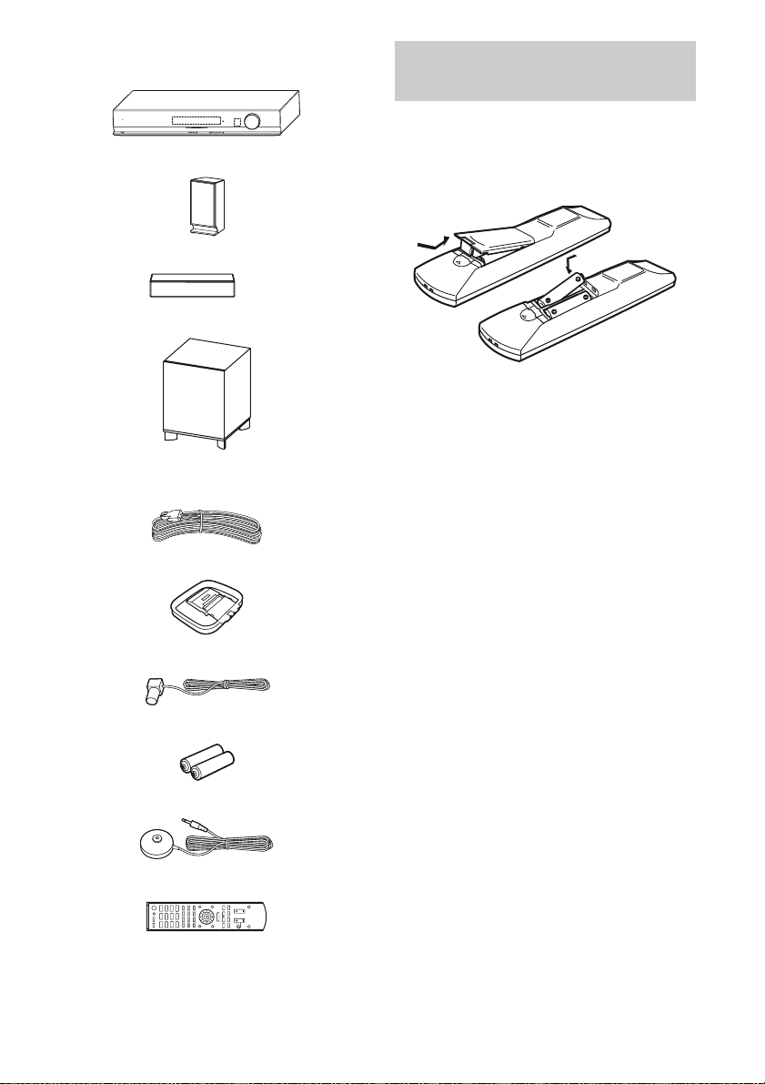
HT-SS370 only
• Receiver (STR-KS370) (1)
POWER /
ACTIVE STANDBY
• Front/Surround speakers (SS-TSB101) (4)
• Center speaker (SS-CTB101) (1)
• Subwoofer (SS-WSB101) (1)
• Speaker cords (5, Red/White/Grey/Blue/
Green)
• AM loop antenna (1)
• FM wire antenna (1)
• R6 (size-AA) batteries (2)
MASTER VOLUME
Inserting batteries into the
remote
Insert two R6 (size-AA) batteries in the
RM-AAU071 Remote Commander.
Observe the correct polarity when installing
batteries.
Notes
• Do not leave the remote in an extremely hot or
humid place.
• Do not use a new battery with old ones.
• Do not mix manganese batteries and other kinds of
batteries.
• Do not expose the remote sensor to direct sunlight
or lighting apparatuses. Doing so may cause a
malfunction.
• If you do not intend to use the remote for an
extended period of time, remove the batteries to
avoid possible damage from battery leakage and
corrosion.
• When you replace the batteries, the remote buttons
may be reset to their initial settings. If this
happens, reassign the buttons again (page 57).
• When the remote no longer operates the receiver,
replace all the batteries with new ones.
• Optimizer microphone (ECM-AC2) (1)
• Remote commander (RM-AAU071) (1)
CD
SAT/
CATV
SA-CD/
VIDEO
TUNER
TV
BD DVD
DMPORT
MENU
O
>
x
X
.
mM
• Operating Instructions (this manual)
• Quick Setup Guide (1)
US
7
Description and location of parts
Receiver
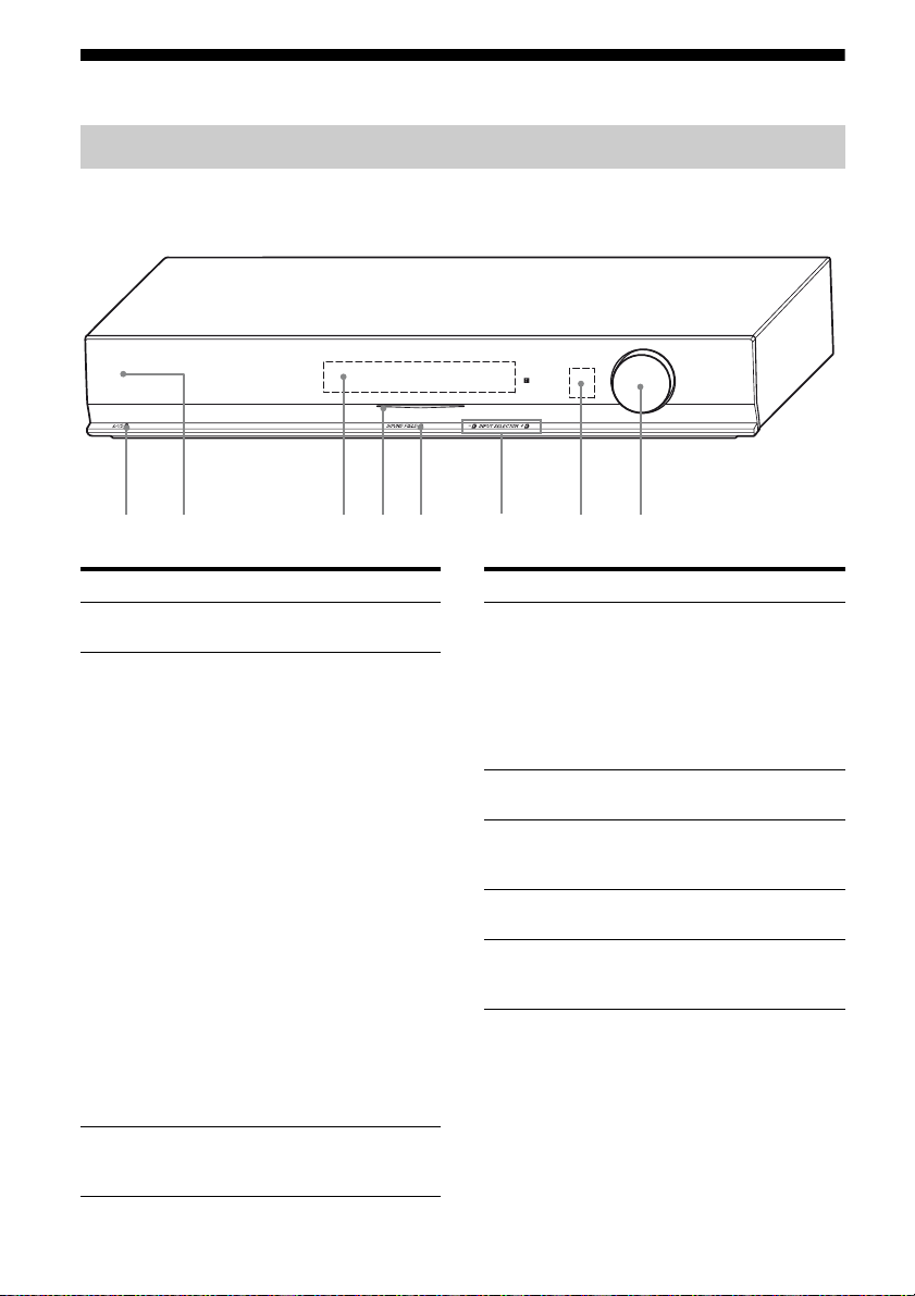
Front view
POWER /
ACTIVE STANDBY
MASTER VOLUME
1 2 3 4 65
Name Function
A ?/1
(on/standby)
B POWER/
ACTIVE
STANDBY
indicator
C Display Displays the current status of
Turns the receiver on or off
(page 24, 31, 58).
Lights up as follows:
Green:
No light:
Amber:
Note
If the POWER/ACTIVE
STANDBY indicator is
flashing, see page 71.
the selected component or a list
of selectable items (page 9).
The receiver is
turned on.
The receiver is in
standby mode, and
Control for HDMI
and S-AIR standby
mode are set to off.
The receiver is in
standby mode, and
Control for HDMI
and/or S-AIR
standby mode are set
to on. However, the
indicator lights off
when “PASS THRU”
is set to “THRU
AUTO” and there is
no signals detected.
78
Name Function
D White indicator Lights up when the
E SOUND FIELD Selects the sound field
F INPUT
SELECTOR +/–
G Remote sensor Receives signals from the
H MASTER
VOLUME
receiver is on and DSPL is
set to on in DISPLAY
function (page 62). Lights
off when the receiver is in
standby mode or DSPL is
set to off in DISPLAY
function.
(page 33).
Selects the input source to
playback (page 29, 31, 32,
35, 37, 38).
remote.
Adjusts the volume level
of all speakers at the same
time (page 30, 32, 67).
US
8
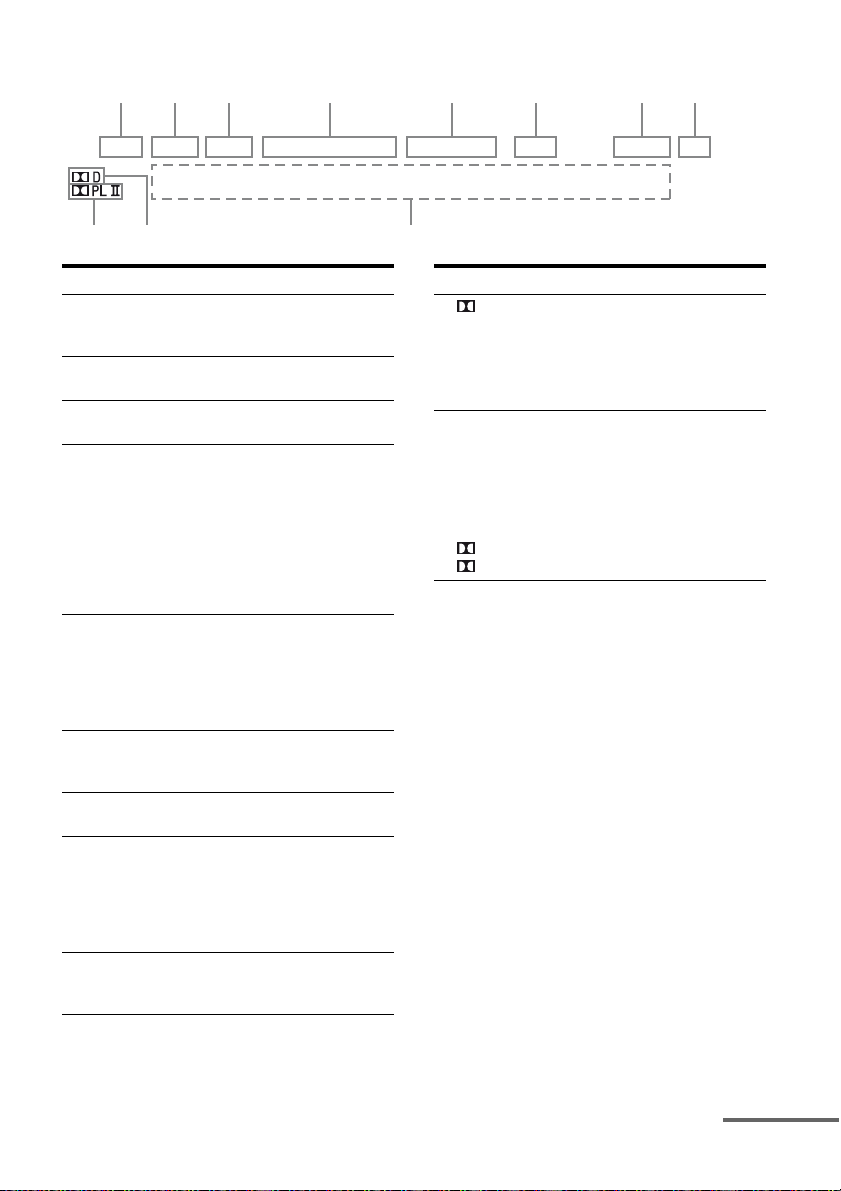
About the indicators on the display
123 4 5 6 78
LPCM NIGHT SLEEP HDMI COAX OPT TUNED ST S-AIR MUTING DTS
qa
q;
Name Function
A LPCM Lights up when Linear PCM
B NIGHT Lights up when the Night Mode
C SLEEP Lights up when the sleep timer is
D Input
indicators
HDMI
COAX
OPT
E Tuning
indicators
TUNED
ST
F S-AIR Lights up when the S-AIR
G MUTING Lights up when the muting
H DTS Lights up when the receiver is
I Message
display area
(Pulse Code Modulation) signals
are input.
function is set to on (page 34).
activated (page 62).
Light up when the digital signal
is input.
Digital signal is input through
the HDMI IN jack.
Digital signal is input through
the COAX IN jack.
Digital signal is input through
the OPT IN jack.
Light up to indicate the current
status of the radio station (page
35).
When receives a radio station.
When broadcasts in stereo mode.
transmitter (not supplied) is
connected.
function is activated.
decoding DTS signals.
Note
When playing a DTS format
disc, be sure that you have made
digital connections.
Displays the volume level,
selected input source, audio
input signal, etc.
9
Name Function
J D Lights up when the receiver is
K Dolby Pro
Logic
indicators
PL
PLII
decoding Dolby Digital signals.
Note
When playing a Dolby Digital
format disc, be sure that you
have made digital connections.
Lights up one of the respective
indicators when the receiver
applies Dolby Pro Logic
processing to 2 channel signals
in order to output the center and
surround channel signals.
Dolby Pro Logic
Dolby Pro Logic II
continued
US
9
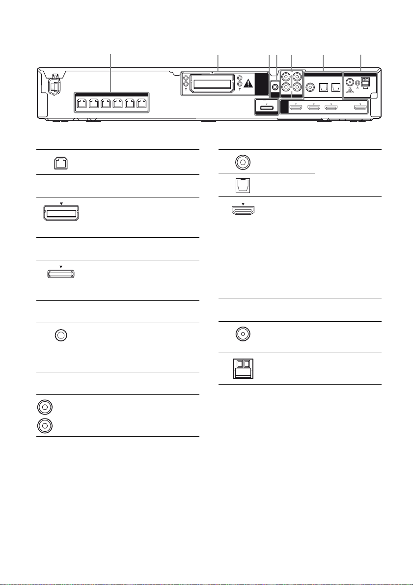
Rear panel
1
2 34 5 6 7
SPEAKERS
FRONT L SUR R SUR L CENTER
FRONT R
SUBWOOFER
A SPEAKERS section
Connects to the supplied speakers
and subwoofer (page 18).
B S-AIR
EZW-T100
slot
C DMPORT
DMPORT
jack
D AUTO CALIBRATION
AUTO CAL
MIC jack
E AUDIO INPUT section
White (L)
Red (R)
AUDIO IN
jacks
Connects to a
wireless transmitter
(not supplied)
(page 48).
Connects to a
DIGITAL MEDIA
PORT adapter (page
20).
Connects to the
supplied optimizer
microphone for the
Auto Calibration
function (page 26).
Connects to a Super
Audio CD player,
CD player, etc.
(page 19, 20).
EZW-T100
DC5V 0.7A MAX
DMPORT
L
R
AUDIO IN
AUDIO IN
AUTO
CAL MIC
COAX IN
VIDEO
SA-CD/CD
TV
HDMI
DVD IN BD IN SAT/CATV IN TV OUT
DIGITAL
OPT IN OPT IN
SAT/CATV
ANTENNA
TV
F DIGITAL INPUT/OUTPUT section
COAX IN
jack
OPT IN jacks
HDMI IN/
OUT jacks
Connects to a
satellite tuner, etc.
(page 23).
Connects to a DVD
player, satellite
tuner, or a Blu-ray
Disc player. The
image is output to a
TV or a projector
while the sound can
be output from a TV
or/and speakers
connected to this
receiver (page 21).
G ANTENNA section
FM
ANTENNA
jack
AM
ANTENNA
terminals
Connects to the
supplied FM wire
antenna (page 24).
Connects to the
supplied AM loop
antenna (page 24).
AM
ARC
10
US
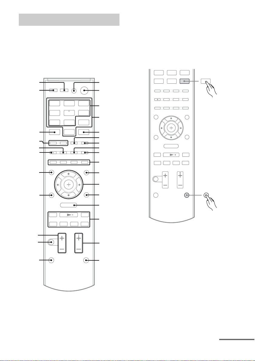
Remote commander
.
mM
>
X
x
DMPORT
TUNER
O
MENU
You can use the supplied remote
RM-AAU071 to operate the receiver and to
control the Sony audio/video components that
the remote is assigned to operate (page 57).
RM-AAU071
wk
wj
1
2
Notes on using SHIFT (Q) and
TV (R) button
SHIFT (Q) button
Press and hold SHIFT (Q), then press the
button with pink printing that you want to use.
Example: Press and hold SHIFT (Q), then
press ENTER (E).
ENTER
BD DVD
TV
DMPORT
wh
wg
wf
wd
ws
O
wa
mM
.
w;
ql
qk
MENU
X
VIDEO
TUNER
SAT/
CATV
SA-CD/
3
CD
4
5
6
7
8
9
0
qa
qs
qd
SHIFT
qf
>
qg
x
qh
qj
continued
11
US
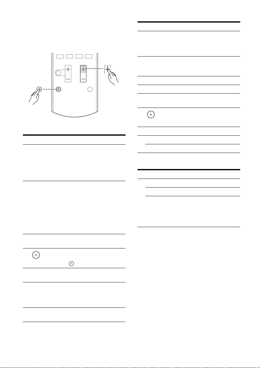
TV (R) button
Press and hold TV (R), then press the button
with yellow printing to control the TV.
Example: Press and hold TV (R), then press
TV CH + (P).
x
X
.
TV
>
TV CH
Basic operations
Remote button Function
B ?/1
(on/standby)
C Input buttons
(VIDEO*)
K AMP MENU Displays the menu of the
L
P SOUND FIELD
S MUTING Activates the muting
T MASTER VOL
,
V/v/B/b
+*/–
+/–
Turns the receiver on or off.
To turn off all Sony
components, press ?/1 (B)
and AV ?/1 ( A) at the same
time (SYSTEM
STANDBY).
Selects the component you
want to use. The buttons are
initial assigned to control
Sony components.
You can change the button
assignments following the
steps in “Changing the input
button assignments” on page
57.
receiver.
Press V, v, B or b to select
the menu items. Then, press
to enter the selection.
Selects a sound field.
function.
Press MUTING again to
restore the sound.
Adjusts the volume level of
all speakers at the same time.
Tuner operations
Remote button Function
D Numeric
buttons
(number 5*)
E ENTER Press and hold SHIFT (Q),
F MEMORY Stores a station.
G D.TUNING Enters direct tuning mode.
I DISPLAY Displays information during
L
N MENU/HOME Displays the tuner menu.
O PRESET +/– Selects a preset station.
,
V/v/B/b
TUNING +/– Scans a station.
Press and hold SHIFT (Q),
then press the numeric
buttons (D) to preset/tune
to the preset stations.
then press ENTER (E) to
enter the selection.
TUNER function.
Selects a menu item and
enters the selection.
DMPORT operations
Remote button Function
O ./> Skips the track.
m/M Fast reverse or fast forward.
N* (playback)/
X (pause, press
again to resume
normal playback)/
x (stop)
Play mode buttons.
To control the component
1 Press one of the input buttons
(TV, BD, DVD or SAT/CATV)
(C) to select the component
you want to operate.
The component assigned to the selected
input button becomes operable.
2 Referring to the following table,
press the corresponding
button for the operation.
12
US
Common operations
Remote button Function
A TV ?/1
AV ?/1
(on/standby)
D Numeric
buttons
(number 5*)
E ENTER Press and hold SHIFT (Q),
J Color buttons Displays an operation guide
L
,
V/v/B/b
Turns on or off the Sony TV
or audio/video components
that the remote is assigned to
operate (page 57).
Press ?/1 (B) and TV ?/1/
AV ?/1 (A) at the same
time to turn off the receiver
and other components that
the remote is assigned to
operate (SYSTEM
STANDBY).
Press and hold SHIFT (Q),
then press the numeric
buttons (D) to select
channels and tracks directly.
then press ENTER (E) to
enter the selection.
on the TV screen when the
color buttons are available.
Follow the operation guide
to perform a selected
operation.
Selects a menu item and
enters the selection.
To control the TV
Press and hold TV (yellow) button (R), then
press the button with yellow printing to control
the TV.
Remote button Function
D Numeric
buttons
(number 5*)
I DISPLAY – Displays the TV’s
Selects channel. Press
ENTER (E) to change
channels immediately.
information on the TV
screen. (Displays the
current channel number,
etc.)
– Press AMP MENU (K),
then press DISPLAY (I)
to display the input stream
information of the TV
when TV is connected via
TV OPT IN jack.
Remote button Function
M TOOLS/
OPTIONS
N MENU/HOME Allows you to select
P TV CH +*/– Selects the next (+) or
S MUTING Activates the muting
T TV VOL +/– Adjusts the volume level.
U O RETURN/
EXIT
V GUIDE Displays the guide when you
W AUDIO* Selects the sound from the
wj THEATER Sets the optimal picture
wk INPUT Selects the TV input signal.
Enables you to access
various viewing options and
change/make adjustments
according to the source and
screen format.
channels or input sources and
change the settings for your
TV.
previous (–) channel.
function.
Returns to the previous
screen of any displayed
menu.
are watching analog or
digital channels.
speaker for a stereo or
bilingual broadcast.
settings automatically for
watching movies, when you
connect a Sony TV that is
compatible with the
THEATER button function.
Also, audio is automatically
switched to the audio output
of this receiver when you
connect the TV and the
receiver with HDMI
connection, and the Control
for HDMI function is set to
on.
continued
13
US

To control the DVD player/recorder,
Blu-ray Disc player/recorder
Remote button Function
H ANGLE Switches to other viewing
I DISPLAY – Displays the playback
M TOOLS/
OPTIONS
N MENU/HOME Displays the menu.
O . Skips chapter.
> Skips forward to the next
m/M Fast reverse or fast forward
N* (playback)/
X (pause, press
again to resume
normal playback)/
x (stop)
U O RETURN/
EXIT
V GUIDE Displays the guide when
W AUDIO* Selects the sound from the
X SUBTITLE Selects the subtitle language
Y TOP MENU Displays the top menu or
POP UP/MENU
Z CLEAR Clear a mistake when you
angles when multi-angle are
recorded on a Blu-ray Disc
or DVD.
information.
– Press AMP MENU (K),
then press DISPLAY (I)
to display the input stream
information for Blu-ray
Disc or DVD.
Enables you to access
various viewing options and
change/make adjustments
according to the source and
screen format.
available chapter.
the disc when pressed
during playback.
Play mode buttons.
Returns to the previous
screen of any displayed
menu.
you are watching analog or
digital channels.
speaker for a stereo or
bilingual broadcast.
when multi-lingual subtitles
are recorded on a Blu-ray
Disc or DVD.
disc menu.
press the incorrect numeric
button.
To control the HDD/DVD COMBO
Remote button Function
N MENU/HOME Displays the menu.
O ./> Specifies the previous or
m/M Fast reverse or fast forward
N* (playback)/
X (pause, press
again to resume
normal playback)/
x (stop)
Y TOP MENU Displays the top menu or
POP UP/MENU
next chapter or track.
the disc when pressed
during playback.
Play mode buttons.
disc menu.
To control the SAT/CATV
Remote button Function
I DISPLAY – Displays the information
N MENU/HOME Displays the menu.
V GUIDE Displays the guide menu.
* These buttons (VIDEO/5, AUDIO, N, SOUND
FIELD +/TV CH +) have tactile dots. Use the
tactile dots as references when operating the
receiver.
during SAT/CATV
function.
– Press AMP MENU (K),
then press DISPLAY (I)
to display the input stream
information for satellite
tuner or cable television
tuner.
Notes
• Some functions explained in this section may not
work depending on the model.
• The above explanation is intended to serve as an
example only. Therefore, depending on the
component, the above operation may not be
possible or may operate differently than described.
In that case, use the remote commander supplied
with the component.
14
US
Getting Started
1: Installing the speakers
Getting Started
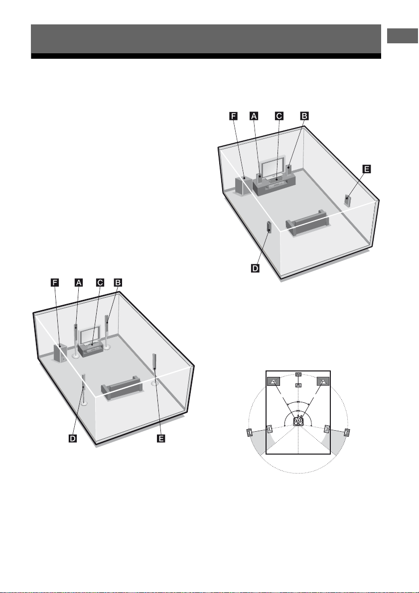
This receiver allows you to use a 5.1 channel
speaker system. To fully enjoy theater-like
multi channel surround sound, be sure to
connect all the speakers (two front speakers, a
center speaker, and two surround speakers)
and a subwoofer (5.1 channel).
You can place your speakers as shown below.
AFront speaker (left)
BFront speaker (right)
CCenter speaker
DSurround speaker (left)
ESurround speaker (right)
FSubwoofer
HT-SF370 only
HT-SS370 only
Notes
• Be sure to use the supplied speakers.
• For HT-SF370, do not lean on the speaker as it
may fall down.
Tips
• The angle A should be the same.
A A
30˚30˚
100˚-120˚100˚-120˚
• Since the subwoofer does not emit highly
directional signals, you can place it wherever you
want.
15
US
Installing the speakers on a flat
surface
Installing the speakers on the
wall
HT-SF370 only
Before you install the center speaker and the
subwoofer, be sure to attach the supplied foot
pads to prevent vibration or movement as
shown in the illustration below.
Note
Attach the small foot pads to the center speaker and
big foot pads to the subwoofer.
Installing the speakers on the
speaker stand
For greater flexibility in positioning the
speakers, you are recommended to use the
speaker stand as below.
Model Speaker stand
HT-SF370 Supplied. For details, refer to
the supplied Quick Setup
Guide.
HT-SS370 Optional WS-FV11 or
WS-FV10D speaker stand
(available only in certain
countries).
For details, refer to the
operating instructions supplied
with the speaker stand.
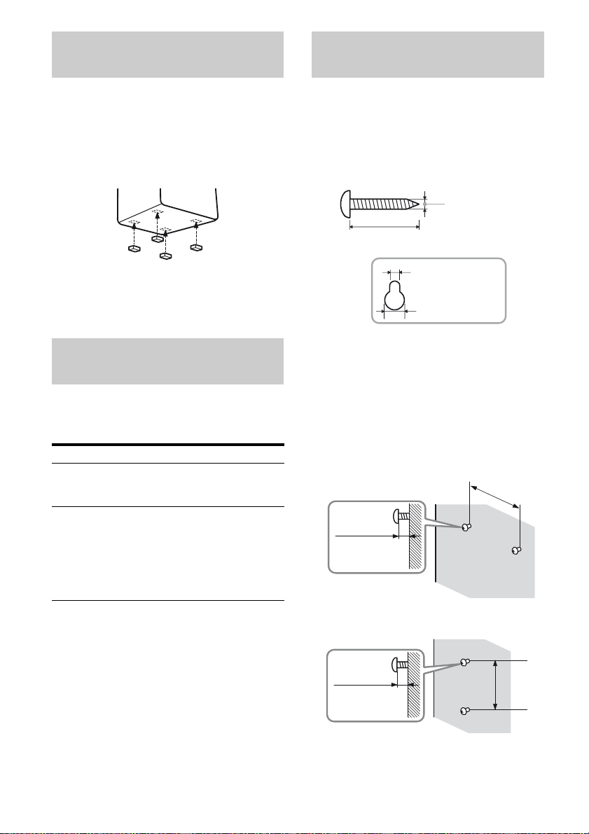
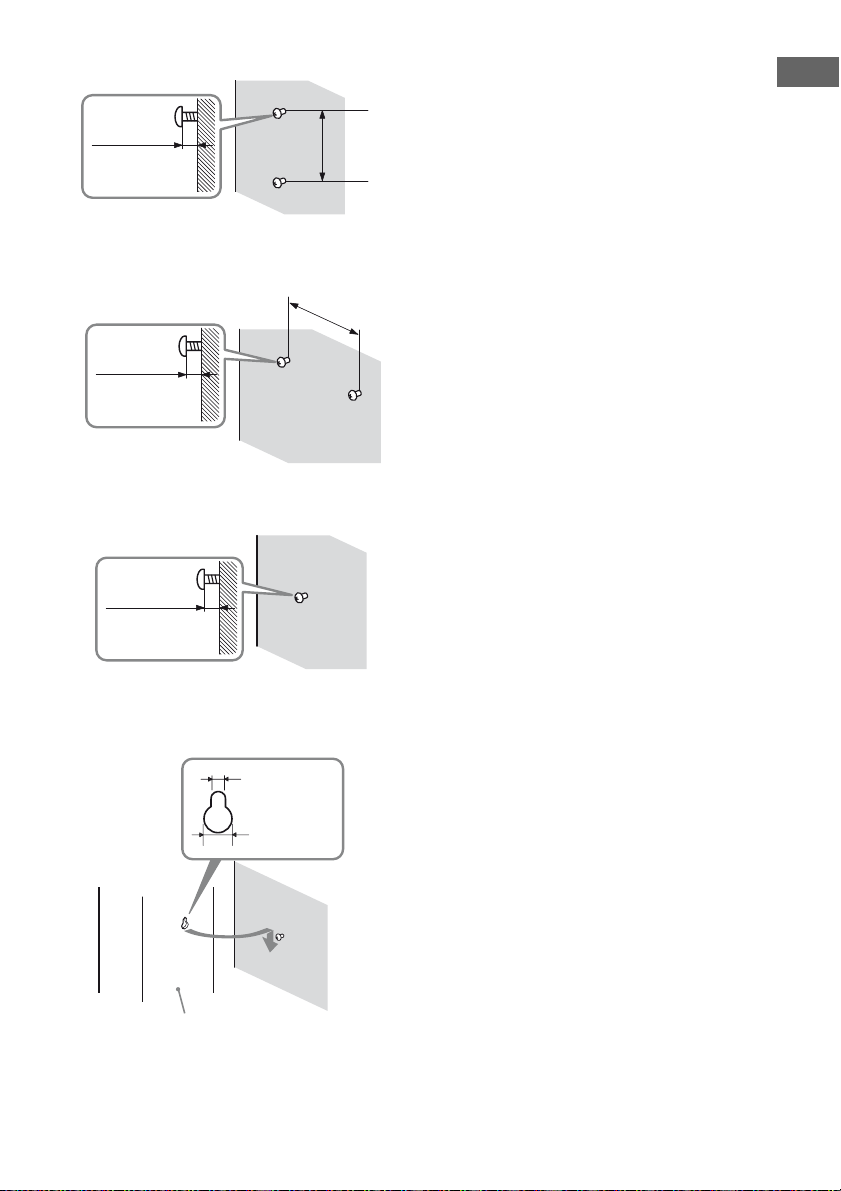
You can install your speakers on the wall.
1 Prepare screws (not supplied)
that are suitable for the hook on
the back of each speaker. See
the illustrations below.
3/16 in (4 mm)
more than 1 in (25 mm)
7/32 in (5 mm)
13/32 in (10 mm)
Hook on the back of the speaker
2 Fasten the screws to the wall.
The screws should protrude
7/32 in to 9/32 in (5 mm to
7 mm).
HT-SF370 only
For the center speaker
6 3/8 in
(160 mm)
7/32 in to 9/32 in
(5 mm to 7 mm)
16
For the front speakers
8 5/8 in
7/32 in to 9/32 in
(5 mm to 7 mm)
US
(217 mm)
For the surround speakers
7/32 in to 9/32 in
(5 mm to 7 mm)
HT-SS370 only
For the center speaker
7/32 in to 9/32 in
(5 mm to 7 mm)
For the front speakers and
surround speakers
7/32 in to 9/32 in
(5 mm to 7 mm)
4 in
(100 mm)
8 5/8 in
(219 mm)
Notes
• Use screws that are suitable for the wall material
and strength. As a plaster board wall is especially
fragile, attach the screws securely to a beam and
fasten them to the wall. Install the speakers on a
vertical and flat wall where reinforcement is
applied.
• Contact a screw shop or installer regarding the
wall material or screws to be used.
• Sony is not responsible for accident or damage
caused by improper installation, insufficient wall
strength or improper screw installation, natural
calamity, etc.
• For HT-SF370, if you install the speakers on the
wall, you do not need to attach the supplied
speaker stand.
Getting Started
3 Hang the speakers on the
screws.
7/32 in (5 mm)
13/32 in
(10 mm)
Rear of speaker
17
US
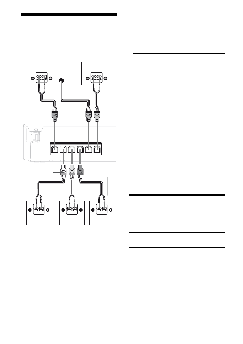
2: Connecting the speakers
Before connecting the cords, be sure to
disconnect the AC power cord.
B
AA
FC
SPEAKERS
FRONT R
SUBWOOFER
CENTERFRONT L SUR R SUR L
Notes on speaker cords
• The connector of the speaker cords are the
same color as the speaker jack to be
connected. When connecting a speaker cord,
be sure to match the colored connector to the
speaker jack on the receiver:
Connector Speaker jack
Red FRONT R
White FRONT L
Grey SUR R
Blue SUR L
Purple SUBWOOFER
Green CENTER
• Be sure to match the speaker cords to the
appropriate terminals on the speakers:
– the speaker cord with the color tube to e
terminal, and the speaker cord without the
color tube to E terminal (for HT-SS370).
– the speaker cord with a stripe line to E
terminal, and the speaker cord without a
stripe line to e terminal (for HT-SF370).
Connector
A
A
E
A Speaker cord (supplied)
AFront speaker (left)
BFront speaker (right)
CCenter speaker
DSurround speaker (left)
ESurround speaker (right)
FSubwoofer
US
18
A
Color tube
D
To connect the speakers
correctly
Check the speaker type by referring to the
speaker label at the rear panel of the speakers.
Character on speaker label Speaker type
HT-SF370 HT-SS370
L FRONT L Front left
R FRONT R Front right
–* CENTER Center
SL SUR L Surround left
SR SUR R Surround right
–* –* Subwoofer
* This speaker does not have character on the
speaker label. For details on the speaker type, see
page 6 (for HT-SF370) or page 7 (for HT-SS370).
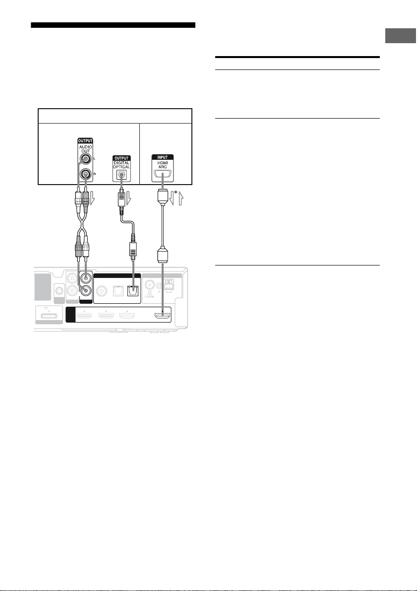
3: Connecting the TV
You can watch the selected input image when
you connect the HDMI OUT jack to a TV.
Before connecting the cords, be sure to
disconnect the AC power cord.
TV
Audio signal
EZW-T100
DC5V 0.7A MAX
DMPORT
AUTO
CAL MIC
A
AUDIO IN
SA-CD/CD
HDMI
B
L
R
DIGITAL
AUDIO IN
COAX IN
OPT IN OPT IN
VIDEO
SAT/CATV
TV
DVD IN BD IN SAT/CATV IN TV OUT
A Audio cord (not supplied)
B Optical digital cord (not supplied)
C HDMI cable (not supplied)
Sony recommends that you use an HDMIauthorized cable or Sony HDMI cable.
Audio/video
signals
C
ANTENNA
TV
AM
ARC
l : Signal flow
It is not necessary to connect all the cords.
Connect audio and video cords according to
the jacks of your components.
Connect To
A or B output the TV sound via the
speakers connected to the receiver.
Be sure to turn off the TV’s volume
or activate the TV’s muting
function.
C output the image to a TV while the
sound can be output from a TV
or/and speakers connected to the
receiver.
When the TV is compatible with
Audio Return Channel (ARC)
function, you can output the TV
sound via the speakers connected
to the receiver without connecting
A or B. For details, see
“Enjoying the TV sound via an
HDMI connection (Audio Return
Channel)” (page 45).
Be sure to turn off the TV’s volume
or activate the TV’s muting
function.
Notes
• Be sure to turn on the receiver when the video and
audio signals of a playback component are being
output to a TV via the receiver. Unless the power is
turned on, neither video nor audio signals will be
transmitted.
• When connecting optical digital cords, insert the
plugs straight in until they click into place.
• Do not bend or tie optical digital cords.
Tip
All the digital audio jacks are compatible with
32 kHz, 44.1 kHz, 48 kHz, and 96 kHz sampling
frequencies.
Getting Started
* When you use Audio Return Channel (ARC)
function, the audio signal is output from the TV to
the receiver.
19
US
4: Connecting the audio/ video components
How to hook up your
components
This section describes how to hook up your
components to this receiver. Before you begin,
see “Component to be connected” below for
the pages which describe how to connect the
audio/video components.
Before connecting the cords, be sure to
disconnect the AC power cord.
After hooking up all your components,
proceed to “5: Connecting the antennas” (page
24).
Super Audio CD player,
L
EZW-T100
DC5V 0.7A MAX
DMPORT
AUTO
CAL MIC
AUDIO IN
SA-CD/CD
HDMI
R
CD player
Audio signal
A
DIGITAL
AUDIO IN
COAX IN
OPT IN OPT IN
VIDEO
SAT/CATV
TV
DVD IN BD IN SAT/CATV IN TV OUT
ANTENNA
TV
AM
ARC
Component to be connected
To connect See
TV page 19
Audio components
page 20
• Super Audio CD player,
CD player
• DIGITAL MEDIA PORT
adapter
Components with HDMI jack page 21
Video components
page 23
• DVD player, DVD recorder
• Satellite tuner, cable television
tuner
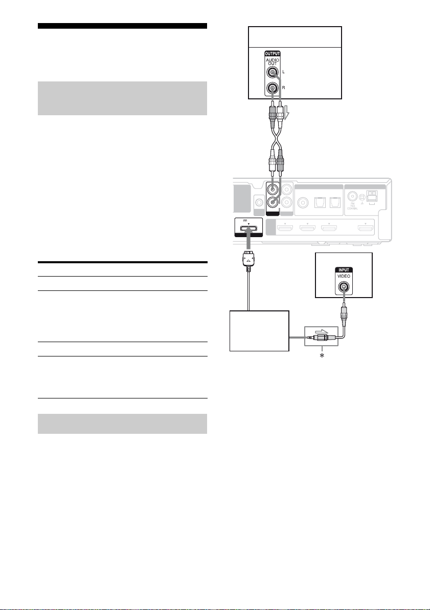
Connecting audio components
The following illustration shows how to
connect audio components such as Super
Audio CD player or CD player and DIGITAL
MEDIA PORT adapter.
You can also view the images on the TV
screen by connecting the video output of the
DIGITAL MEDIA PORT adapter to the video
input of the TV. However, depending on the
DIGITAL MEDIA PORT adapter, video
output may not be possible.
TV
B
DIGITAL MEDIA
PORT adapter
l : Signal flow
A Audio cord (not supplied)
B Video cord (not supplied)
* The type of connector varies depending on the
DIGITAL MEDIA PORT adapter.
For details, refer to the operating instructions
supplied with the DIGITAL MEDIA PORT
adapter.
20
US
Notes on connecting DIGITAL
MEDIA PORT adapter
• Do not connect or disconnect the DIGITAL
MEDIA PORT adapter while the receiver is
turned on.
• Be sure to make DMPORT connections
firmly, insert the connector straight in.
• As the connector of the DIGITAL MEDIA
PORT adapter is fragile, be sure to handle
with care when placing or moving the
receiver.
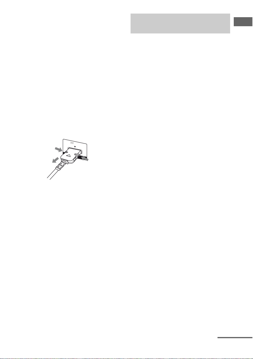
• When connecting the DIGITAL MEDIA
PORT adapter, be sure the connector is
inserted with the arrow mark facing towards
the arrow mark on the DMPORT jack. To
detach the DIGITAL MEDIA PORT
adapter, press and hold both sides of the
connector and then pull out the connector.
DC5V 0.7A MAX
1
DMPORT
2
1
Connecting components with
HDMI jacks
HDMI is the abbreviated name for HighDefinition Multimedia Interface. It is an
interface which transmits video and audio
signals in digital format.
Sony recommends that you connect
components to the receiver using an HDMI
cable.
By connecting Sony “BRAVIA” Synccompatible components using HDMI cables,
operations can be simplified. See ““BRAVIA”
Sync Features” (page 39).
HDMI features
• A digital audio signals transmitted by HDMI
can be output from the speakers connected to
the receiver. This signal supports Dolby
Digital, DTS and Linear PCM.
• This receiver supports Deep Color and
xvYCC transmission.
Notes on connecting cables
• Use a High Speed HDMI cable. If you use a
Standard HDMI cable, 1080p or Deep Color
images may not be displayed properly.
• Sony recommends that you use an HDMI
authorized cable or Sony HDMI cable.
• We do not recommend using an HDMI-DVI
conversion cable. When you connect an
HDMI-DVI conversion cable to a DVI-D
component, the sound and/or the image may
not be output.
Getting Started
continued
21
US
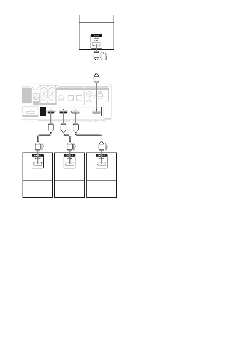
TV, etc.
Audio/video
signals
A
EZW-T100
DC5V 0.7A MAX
DMPORT
AUTO
CAL MIC
AUDIO IN
SA-CD/CD
HDMI
L
R
DIGITAL
AUDIO IN
COAX IN
OPT IN OPT IN
VIDEO
SAT/CATV
TV
DVD IN BD IN SAT/CATV IN
ANTENNA
TV
AM
ARC
TV OUT
AAA
Audio/video
signals
DVD playe r
Audio/video
signals
Blu-ray Disc
player
Audio/video
signals
Satellite tuner,
cable television
tuner
l : Signal flow
A HDMI cable (not supplied)
Sony recommends that you use an HDMIauthorized cable or Sony HDMI cable.
* When you use Audio Return Channel (ARC)
function, the audio signal is output from the TV to
the receiver.
Notes
• When the TV is compatible with Audio Return
Channel (ARC) function, the TV sound will
automatically output from the speakers connected
to the receiver. If not, see page 19 for the audio
connection of TV to the receiver. Be sure to set
“ARC” to “ARC ON” in SET HDMI menu (page
45).
• All the HDMI jacks on the receiver function in the
same way. For example, you can connect a
“PlayStation 3” etc., to any available HDMI jack.
Notes on HDMI connections
• An audio signal input to the HDMI IN jack
is output from the SPEAKERS jacks and
HDMI OUT jack. It is not output from any
other audio jacks.
• Video signals input to the HDMI IN jack can
only be output from the HDMI OUT jack.
• The multi/stereo area audio signals of a
Super Audio CD are not output.
• Audio signals (sampling frequency, bit
length, etc.) transmitted from an HDMI jack
may be suppressed by the connected
component. Check the setup of the
connected component if the image is poor or
the sound does not come out of a component
connected via the HDMI cable.
• Sound may be interrupted when the
sampling frequency, the number of channels
or the audio format of the audio output
signals from the playback component is
switched.
• When the connected component is not
compatible with copyright protection
technology (HDCP), the image and/or the
sound from the HDMI OUT jack may be
distorted or may not be output.
In this case, check the specification of the
connected component.
• You can enjoy multi channel Linear PCM
only with an HDMI connection.
• Set the image resolution of the playback
component to 720p, 1080i or 1080p when
you output 96 kHz multi channel sound over
an HDMI connection.
• You may need to make certain settings on
the image resolution of the player before you
can enjoy multi channel Linear PCM. Refer
to the operating instructions of the player.
• Refer to the operating instructions of each
component connected for details.
• Not every HDMI component supports all
functions that are defined by the specified
HDMI version. For example, components
that support HDMI, version 1.4, may not
support Audio Return Channel (ARC).
22
US
Connecting video components
The following illustration shows how to
connect video components such as DVD
player, DVD recorder, etc.
It is not necessary to connect all the cords.
Connect audio and video cords according to
the jacks of your components.
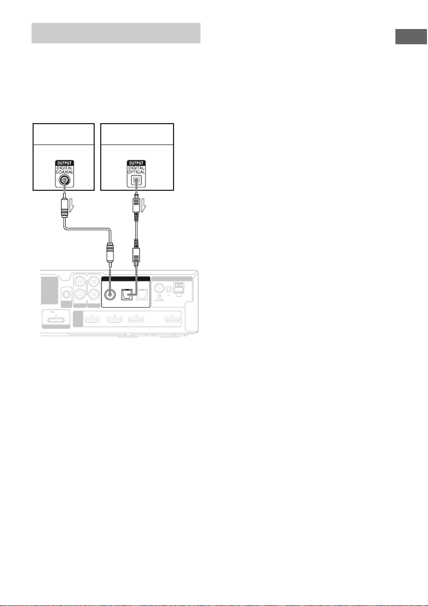
DVD player,
DVD recorder
Audio signal
EZW-T100
AUDIO IN
AUTO
SA-CD/CD
CAL MIC
DC5V 0.7A MAX
HDMI
DMPORT
AB
Satellite tuner,
cable television tuner
Audio signal
L
R
DIGITAL
AUDIO IN
COAX IN
OPT IN OPT IN
VIDEO
SAT/CATV
TV
DVD IN BD IN SAT/CATV IN TV OUT
ANTENNA
TV
AM
ARC
Notes
• If you connect a DVD player/recorder, be sure to
change the initial setting of the VIDEO button on
remote so that you can use the button to control
your DVD player/recorder. For details, see
“Changing the input button assignments” (page
57).
• To input multi channel digital audio from the DVD
player, set the digital audio output setting on the
DVD player. Refer to the operating instructions
supplied with the DVD player.
• When connecting optical digital cords, insert the
plugs straight in until they click into place.
• Do not bend or tie optical digital cords.
• Be sure to connect the video output of the DVD
player and DVD recorder to the TV, so that the
image is displayed on the TV. Refer to the
operating instructions of each connected
component for details.
• You cannot do recording on the DVD recorder via
this receiver. For details, refer to the operating
instructions supplied with the DVD recorder.
Tip
All the digital audio jacks are compatible with
32 kHz, 44.1 kHz, 48 kHz, and 96 kHz sampling
frequencies.
Getting Started
l : Signal flow
A Coaxial digital cord (not supplied)
B Optical digital cord (not supplied)
23
US
 Loading...