

Page 1

HD ELECTRONIC VIEWFINDER
HDVF-550
電気製品は、安全のための注意事項を守らないと、
火災や人身事故になることがあります。
このオペレーションマニュアルには、事故を防ぐための重要な注意事項と製品
の取り扱いかたを示してあります。このオペレーションマニュアルをよくお読
みのうえ、製品を安全にお使いください。お読みになったあとは、いつでも見ら
れるところに必ず保管してください。
OPERATION MANUAL [Japanese/English]
1st Edition
Page 2
日本語
安全のために
電気製品は、安全のための注意事項を守らないと、火災や感電などにより死亡や
大けがなど人身事故につながることがあり、危険です。
事故を防ぐために次のことを必ずお守りください。
安全のための注意事項を守る
4 ページの注意事項をよくお読みください。
定期点検を実施する
長期間安全に使用していただくために、定期点検を実施することをおすすめしま
す。点検の内容や費用については、ソニーのサービス担当者または営業担当者に
ご相談ください。
故障したら使用を中止する
ソニーのサービス担当者、または営業担当者にご連絡ください。
万一、異常が起きたら
警告表示の意味
このオペレーションマニュアルお
よび製品では、次のような表示を
しています。表示の内容をよく理
解してから本文をお読みください。
この表示の注意事項を守らないと、
感電やその他の事故によりけがを
したり周辺の物品に損害を与えた
りすることがあります。
注意を促す記号
・ 異常な音、におい、煙が出たら
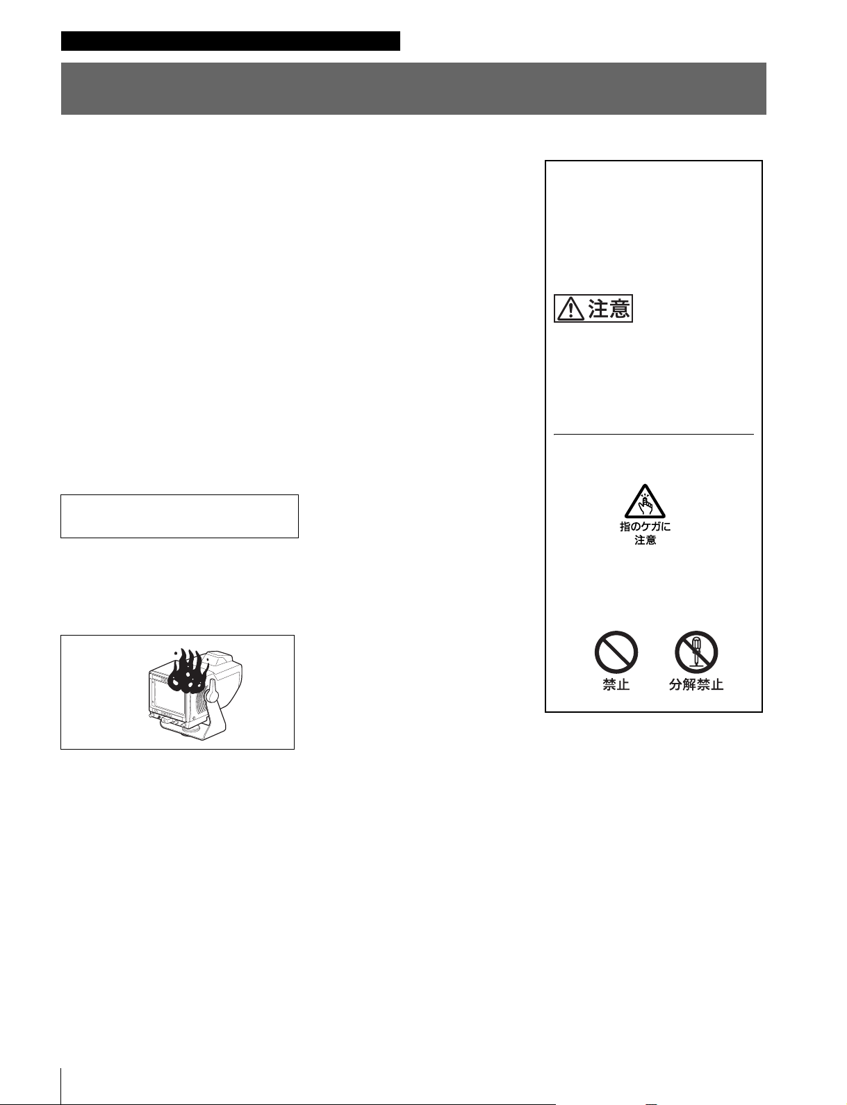
・ 落下させたら
m
a カメラの電源を切る。
b 接続ケーブルを抜く。
c ソニーのサービス担当者、または営業担当者に修理を依頼する。
炎が出たら
m
a すぐにカメラの電源を切り、消火する。
行為を禁止する記号
2
Page 3
目次
注意 ............................................................................................................................4
概要 ...................................................................................................................................5
各部の名称と働き ............................................................................................................6
カメラに取り付ける ........................................................................................................7
電源を入れる....................................................................................................................8
位置を調整する................................................................................................................9
パンニング調整.............................................................................................................................................9
チルティング調整 .......................................................................................................................................9
アクセサリーを取り付ける..........................................................................................10
フードの取り付け ....................................................................................................................................10
ナンバープレートの取り付け .........................................................................................................10
仕様 ................................................................................................................................11
JP
目次
3
Page 4
分解しない、改造しない
分解したり、改造したりすると、感電の
原因となります。
ビューファインダー内部の調整や点検を
行う必要がある場合は、必ずソニーの
サービス担当者にご依頼ください。
内部に水や異物を入れない
水や異物が入ると火災や感電の原因とな
ります。
万一、水や異物が入ったときは、すぐに
カメラの電源を切り、接続ケーブルを抜
いて、ソニーのサービス担当者または営
業担当者にご相談ください。
指はさみに注意する
チルティング調整、パンニング調整のと
きは、指はさみに注意してください。
油煙、湯気、湿気、ほこりの
多い場所では設置・使用しな
い
上記のような場所で設置・使用すると、
火災や感電の原因となります。
フード、ケーブルなどを持っ
て移動しない
フード、ケーブルなどがはずれて落下
し、けがの原因となります。
カメラを三脚に固定しない状
態ではビューファインダーを
取り付けない
カメラ、ビューファインダーが転倒し、
火災や感電の原因となります。
4
注意
Page 5

概要
HDVF-550 は、カメラに取り付けて使用する 5 型白黒
ビューファインダーです。
主な特長を以下に示します。
省エネルギー設計
入力電圧の許容範囲が広く(10.5V〜17V)、低消費電力
(14W)です。
高解像度
高性能ブラウン管を採用し、水平解像度 650本以上という
高解像度を実現しています。
両エッジピーキング回路採用
画像の両エッジで映像信号の補正を行うので、シャープな
画像が得られ、フォーカス合わせが容易になります。
大型アップタリーランプ
点灯時、白色から赤色に変わることによって、認識性を高
めた大型アップタリーランプを装備しています。
ナンバープレートが取り付け可能で、複数カメラでのオペ
レーションに対応します。
アップタリーランプの明るさは被写体に影響を与えないよ
うに調整することもできます。
2 系統のタリーランプ
レッドタリー、グリーンタリー信号が入力されると、それ
ぞれに対応したランプが点灯します。
優れた操作性
パンニングは左右方向にそれぞれ 90°、チルティングは上
下にそれぞれ 40°の範囲で調整できます。
本体は約 1.9kg と軽量で、堅牢なマグネシウムダイキャス
トボディを採用しており、重心移動もないため、操作性に
すぐれています。
スタジオ用屋内フード(付属)および OB
用屋外フード VFH-550(別売)を取り付
け可能
堅牢で操作性のよいスタジオ用屋内フードと、遮光性に優
れている OB 用屋外フード(VFH-550)を用意しています。
概要
5
Page 6
各部の名称と働き
6
9
8
7
12
3
4
5
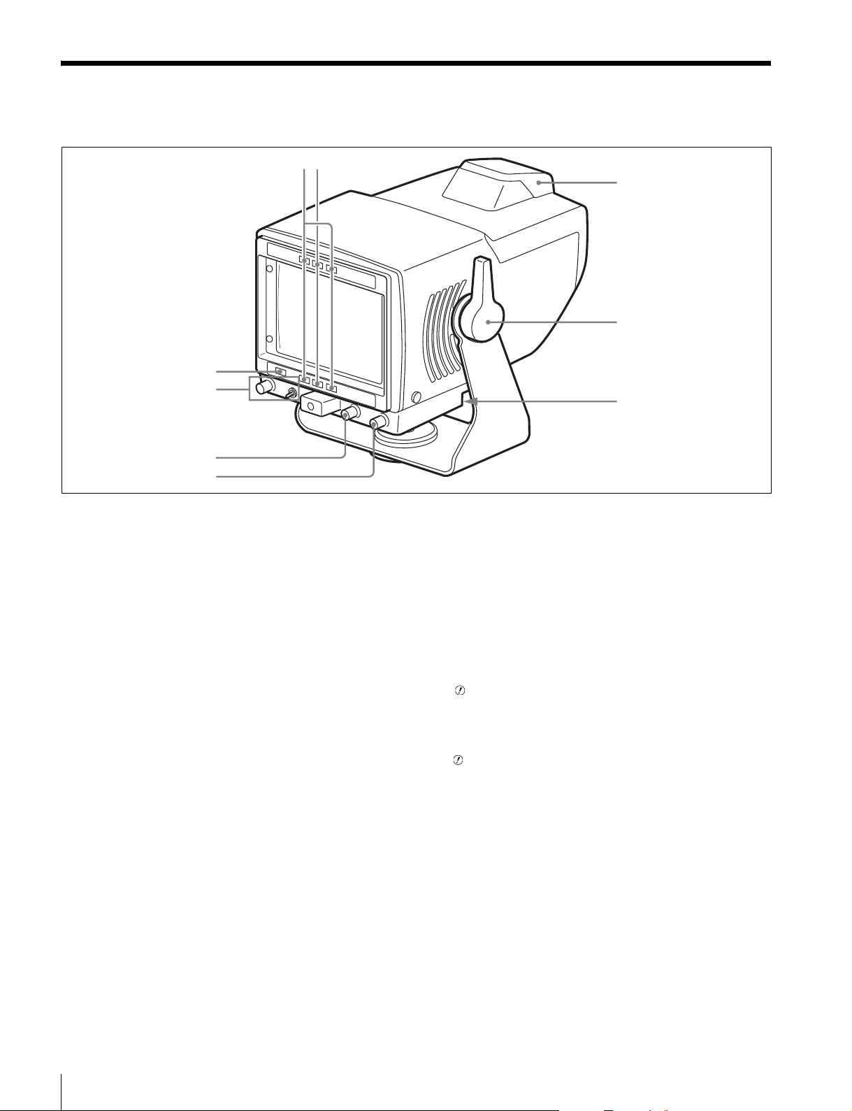
a RTALLYランプ(赤)
レッドタリー信号が入力されると、点灯します。
b GTALLYランプ(緑)
グリーンタリー信号が入力されると、点灯します。
c アップタリーランプ(赤)
ナンバープレート(付属)が取り付け可能です。
TALLYON/OFF スイッチを ON にすると、RTALLYラ
ンプと同様に働きます。
d チルティングロックレバー
チルティングポジションを任意の位置でロックできます。
e 20 ピンコネクター
接続ケーブル(付属)を使って、カメラの VF コネクター
と接続します。
カメラから電源、映像信号、タリー信号が入力されます。
f CONTRAST つまみ
画像のコントラスト(濃淡)を調整します。
g BRIGHT つまみ
画像の明るさを調整します。
1)
1)
調整するには、PEAKING スイッチを LOW(ピーキング周
波数レベル低)または HIGH(ピーキング周波数レベル高)
にします。レンズのフォーカスを合わせやすい方で LOW
か HIGH のどちらか選択します。
続いて PEAKING つまみで画像の輪郭を補正します。
PEAKING つまみを時計方向に回すと画像の輪郭が強調さ
れます。
調整しないときは、PEAKING スイッチを OFF にします。
i (注意)ランプ
カメラがある特定の状態になったときオレンジ色に点灯し
ます。どの状態で点灯させるかは、カメラで設定できます。
◆ ランプが点灯する条件を設定 / 確認する方法については、使
用しているカメラのオペレーションマニュアルをご覧ください。
1)
これらのつまみによる調整は、カメラの出力信号には影響あり
ません。
h PEAKING スイッチと PEAKING つまみ
画像の輪郭を調整します。
各部の名称と働き
6
1)
Page 7
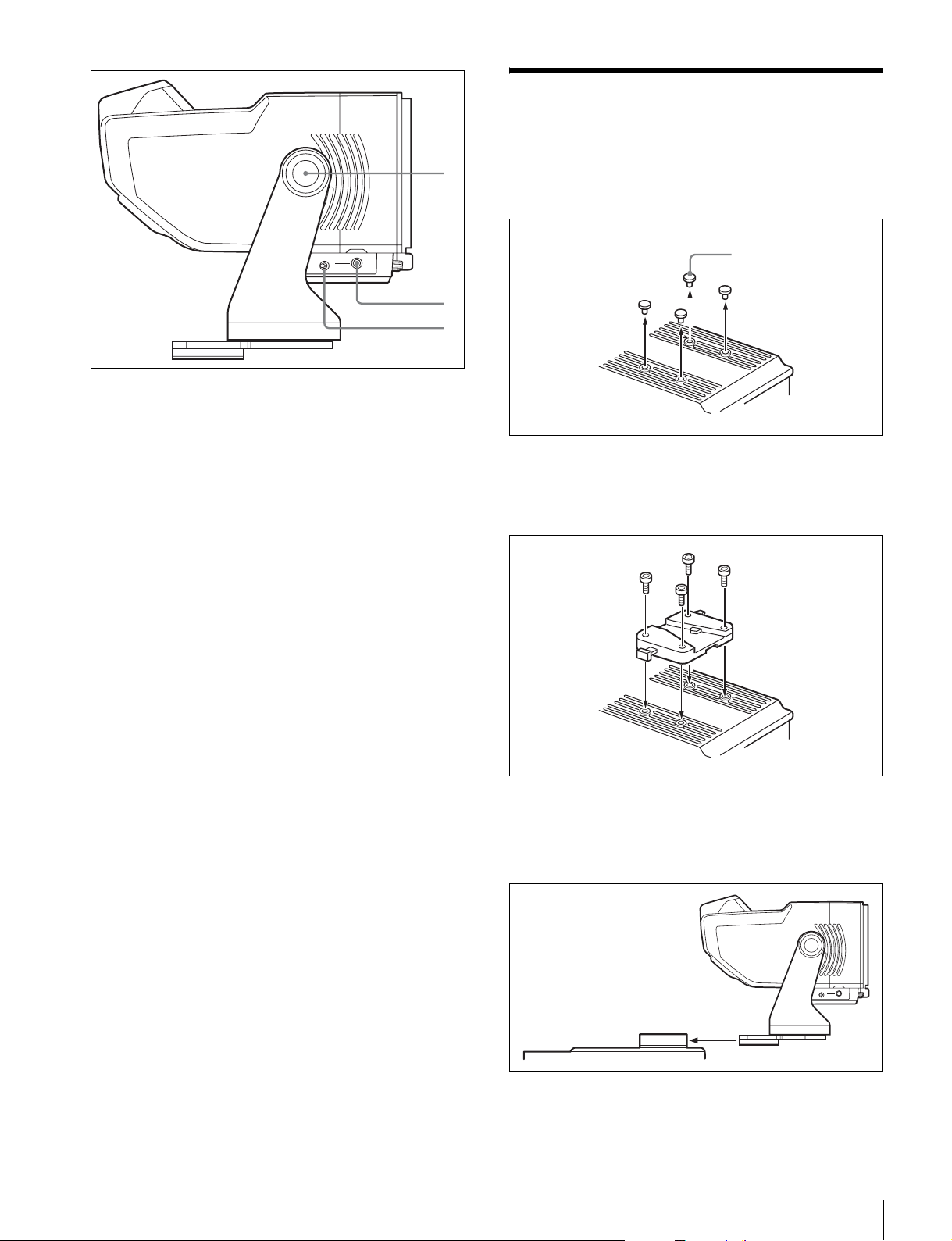
j チルティングノブ
スムースなチルト動作に調整できます。
0
qa
qs
カメラに取り付ける
1
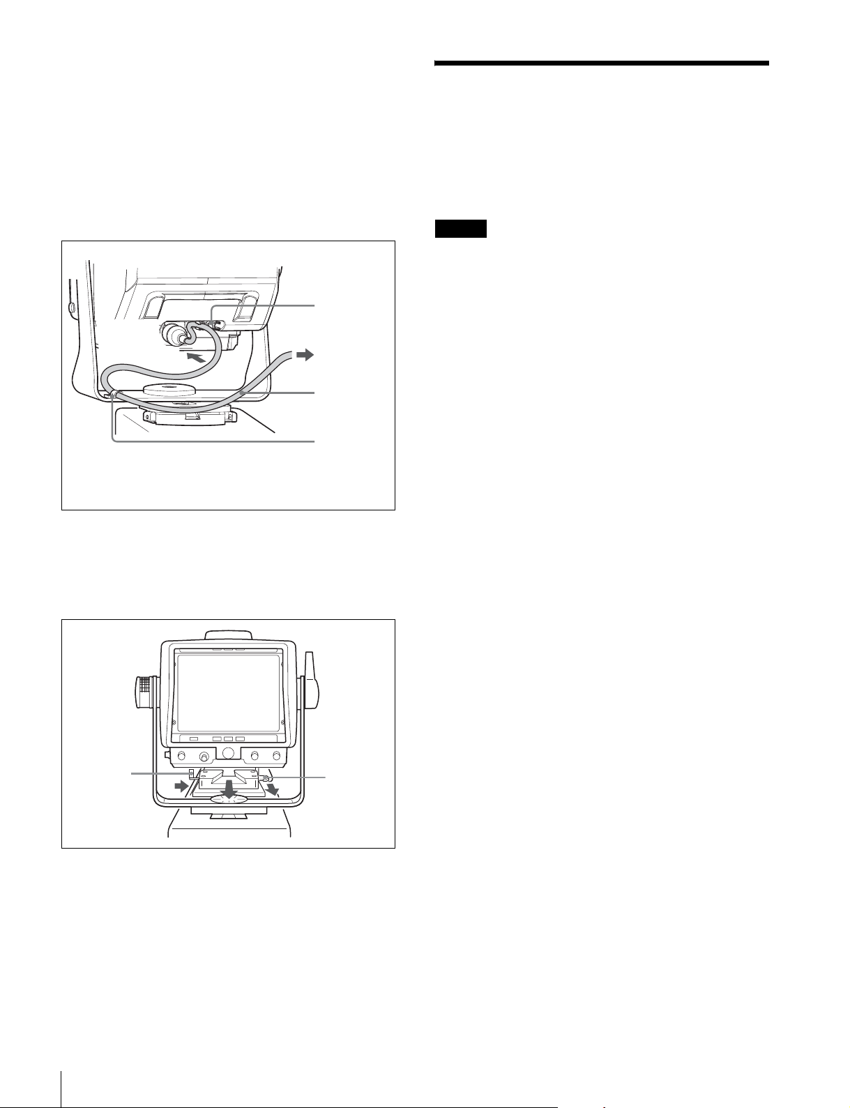
カメラからプラスチックキャップ(4本)を取りはず
す。
プラスチックキャップ
k DIMMER つまみ
アップタリーランプの明るさを調整します。
l TALLYON/OFF(タリーオン/オフ)スイッチ
ON にすると、アップタリーランプが RTALLY ランプと
同様に働きます。
2
六角レンチ(付属)と六角ボルト(4 × 12、4 本、付属)
を使って、V ウェッジシューアタッチメント(付属)
をカメラに取り付ける。
3
本機を V ウェッジシューアタッチメントにしっかりと
差し込む。
取り付けると、カチッと音がして固定されます。
カメラに取り付ける
7
Page 8
4
カメラのビューファインダーを取りはずす。
取りはずしかたについては、カメラのオペレーション
マニュアルをご覧ください。
5
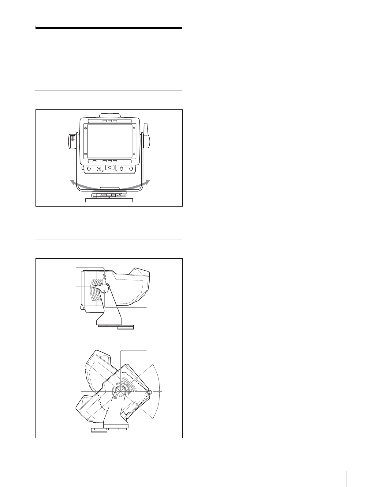
接続ケーブル(付属)を使用して、HDVF-550 の 20 ピン
コネクターとカメラの VF コネクターとを接続する。
接続ケーブル(付属)は、下図のように2か所のクラ
ンプで固定してください。
クランプ
20 ピン
コネクターへ
1)
ビューファインダーの位置によっては、このクランプから
接続ケーブルをはずしてください。
カメラの VF
コネクターへ
接続ケーブル
クランプ
電源を入れる
カメラの電源を入れると、ビューファインダーの電源も入
ります。
電源を入れて数秒後に、画像が表示されます。
ご注意
BRIGHT つまみが左いっぱいになっていると、画像が表示
されないことがあります。
1)
HDVF-550 をカメラから取りはずすには
レバーを引きながら、ボタンを押して下図のようにビュー
ファインダーを手前に引いて取りはずします。
ボタン
2
1
レバー
8
電源を入れる
Page 9
位置を調整する
ビューファインダーの位置を以下のように調整して、お使
いください。
パンニング調整
180°
1
チルティングロックレバーをフリクション(可動)の
位置にする。
2
チルティングノブを回して、スムースなチルト動作を
決める。
3
チルティング角度を調整する。
チルティング角度を固定するときは、チルティング
ロックレバーをロック(固定)の位置にする。
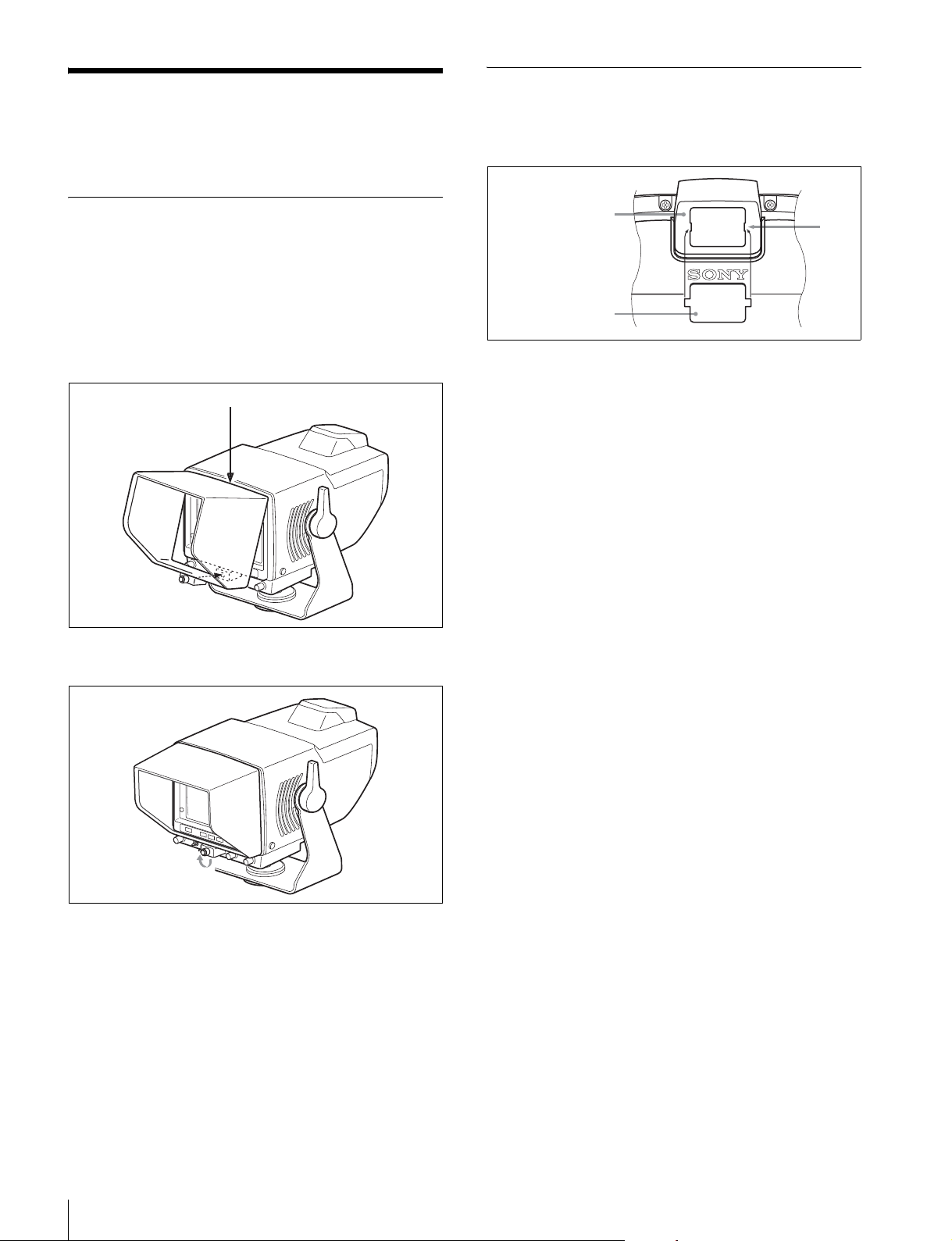
正面をセンターとして左右に 90°ずつ動かすことができま
す。
チルティング調整
ロック(固定)
の位置
フリクション
(可動)の位置
チルティング
ロックレバー
チルティング
ノブ
40°
ゆるむ
しまる
40°
位置を調整する
9
Page 10
アクセサリーを取り付け
る
ナンバープレートの取り付け
ナンバープレート(付属)の左右のつめをアップタリーラ
ンプの溝に差し込みます。
フードの取り付け
OB 用屋外フード VFH-550(別売)の取り付けかたは、ス
タジオ用モニターフード(付属)と同じです。
ここでは、スタジオ用モニターフード(付属)の取り付け
かたとして説明します。
1
溝に引っかけて、取り付ける。
溝
2
ネジを回して、固定する。
アップタリーランプ
ナンバープレート
溝
1
アクセサリーを取り付ける
10
Page 11
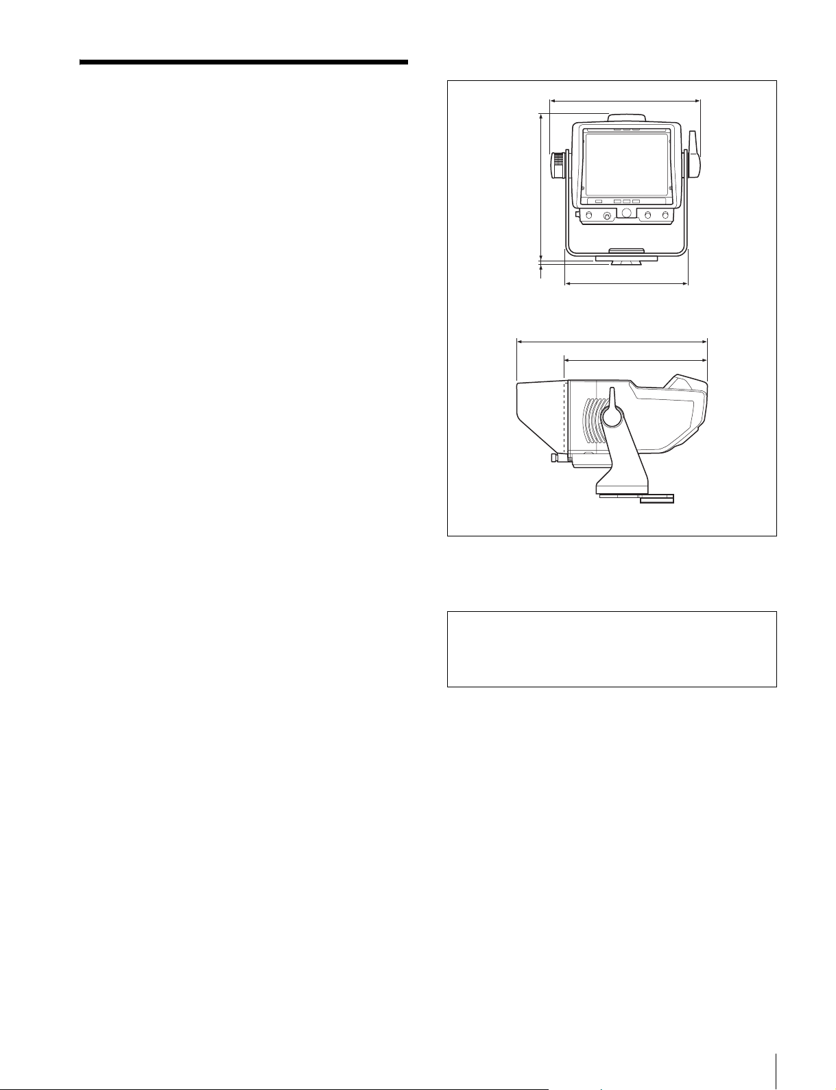
外形寸法図
仕様
ブラウン管 5 型モノクローム
有効画面寸法 16:9 モード96 × 54mm(幅×高さ)
信号方式 BTA-S001 および SMPTE-274M 規格準拠
輝度 400cd/m
解像度 650 本以上(中心)、550本以上(周辺)
入力端子 20 ピンコネクター
映像入力:1Vp-p、三値同期、75Ω
周波数特性 − 3dB(25MHz)以内
電源 DC10.5V 〜 17V、定格 12V
消費電力 14W
動作周囲温度 − 20 ℃〜+ 45 ℃
保存温度 − 20 ℃〜+ 60 ℃
動作周囲湿度 0%〜 90%
結露しないこと
質量 本体:約 2.3kg(フードを含む)
付属品 V ウェッジシューアタッチメント(1)
六角レンチ(1)
接続ケーブル(1)
スタジオ用モニターフード(1)
ナンバープレート(1)
六角穴付きボルト(4)
オペレーションマニュアル(1)
別売品 屋外フードVFH-550
関連製品 HD カラーカメラHDC1500 シリーズ
2
191
188
6
156
291
219
単位:mm
本機の仕様および外観は、改良のため予告なく変更するこ
とがありますが、ご了承ください。
お使いになる前に、必ず動作確認を行ってください。故障
その他に伴う営業上の機会損失等は保証期間中および保証
期間経過後にかかわらず、補償はいたしかねますのでご了
承ください。
仕様
11
Page 12

English
For the customers in the U.S.A.
This equipment has been tested and found to comply with
the limits for a Class A digital device, pursuant to Part 15
of the FCC Rules. These limits are designed to provide
reasonable protection against harmful interference when
the equipment is operated in a commercial environment.
This equipment generates, uses, and can radiate radio
frequency energy and, if not installed and used in
accordance with the instruction manual, may cause
harmful interference to radio communications. Operation
of this equipment in a residential area is likely to cause
harmful interference in which case the user will be
required to correct the interference at his own expense.
You are cautioned that any changes or modifications not
expressly approved in this manual could void your
authority to operate this equipment.
All interface cables used to connect peripherals must be
shielded in order to comply with the limits for a digital
device pursuant to Subpart B of Part 15 of FCC Rules.
For the customers in Europe
This product with the CE marking complies with the EMC
Directive issued by the Commission of the European
Community.
Compliance with this directive implies conformity to the
following European standards:
• EN55103-1 : Electromagnetic Interference(Emission)
• EN55103-2 : Electromagnetic Susceptibility(Immunity)
This product is intended for use in the following
Electromagnetic Environments: E1 (residential), E2
(commercial and light industrial), E3 (urban outdoors),
E4 (controlled EMC environment, ex. TV studio).
Pour les clients en Europe
Ce produit portant la marque CE est conforme à la
Directive sur la compatibilité électromagnétique (EMC)
émise par la Commission de la Communauté européenne.
La conformité à cette directive implique la conformité aux
normes européennes suivantes :
• EN55103-1 : Interférences électromagnétiques
(émission)
• EN55103-2 : Sensibilité électromagnétique (immunité)
Ce produit est prévu pour être utilisé dans les
environnements électromagnétiques suivants : E1
(résidentiel), E2 (commercial et industrie légère), E3
(urbain extérieur) et E4 (environnement EMC contrôlé, ex.
studio de télévision).
• EN55103-1: Elektromagnetische Verträglichkeit
(Störaussendung)
• EN55103-2: Elektromagnetische Verträglichkeit
(Störfestigkeit)
Für die folgenden elektromagnetischen Umgebungen: E1
(Wohnbereich), E2 (kommerzieller und in beschränktem
Maße industrieller Bereich), E3 (Stadtbereich im Freien)
und E4 (kontrollierter EMV-Bereich, z.B. Fernsehstudio).
For the customers in Europe
The manufacturer of this product is Sony Corporation, 17-1 Konan, Minato-ku, Tokyo, Japan.
The Authorized Representative for EMC and product
safety is Sony Deutschland GmbH, Hedelfinger Strasse
61, 70327 Stuttgart, Germany. For any service or
guarantee matters please refer to the addresses given in
separate service or guarantee documents.
Pour les clients en Europe
Le fabricant de ce produit est Sony Corporation, 1-7-1
Konan, Minato-ku, Tokyo, Japon.
Le représentant autorisé pour EMC et la sécurité des
produits est Sony Deutschland GmbH, Hedelfinger Strasse
61, 70327 Stuttgart, Allemagne. Pour toute question
concernant le service ou la garantie, veuillez consulter les
adresses indiquées dans les documents de service ou de
garantie séparés.
Für Kunden in Europa
Der Hersteller dieses Produkts ist Sony Corporation, 1-7-1
Konan, Minato-ku, Tokyo, Japan.
Der autorisierte Repräsentant für EMV und
Produktsicherheit ist Sony Deutschland GmbH,
Hedelfinger Strasse 61, 70327 Stuttgart, Deutschland. Bei
jeglichen Angelegenheiten in Bezug auf Kundendienst
oder Garantie wenden Sie sich bitte an die in den separaten
Kundendienst- oder Garantiedokumenten aufgeführten
Anschriften.
Für Kunden in Europa
Dieses Produkt besitzt die CE-Kennzeichnung und erfüllt
die EMV-Richtlinie der EG-Kommission.
Angewandte Normen:
12
Page 13
Table of Contents
Overview .............................................................................. 14
Functions of Parts and Controls........................................ 15
Attaching to the Camera..................................................... 16
Turning on the HDVF-550 ................................................... 17
Adjusting the Viewfinder Position ..................................... 18
Panning Adjustment ............................................................... 18
Tilt Adjustment....................................................................... 18
Attaching Accessories........................................................ 19
Attaching a Hood.................................................................... 19
Attaching a Number Plate ...................................................... 19
Specifications...................................................................... 20
GB
Table of Contents
13
Page 14

Overview
The HDVF-550 electronic viewfinder is a 5-type
monochrome electronic viewfinder designed for
attachment to a camera.
The main features are as shown below.
Low power consumption
Wide voltage range of 10.5 V to 17 V.
Low power consumption (approx. 14 W).
High resolution
High-resolution picture tube, with horizontal resolution
of over 650 lines.
Phase-corrected peaking circuit (for both
side edges)
Adoption of the peaking circuit ensures sharp pictures
and thus make forcussing easier.
Large up-tally lamp
The up-tally lamp is large and easier to see by switching
from white to red.
The up-tally lamp with the supplied number plate
attached can be used for the multi-camera operations.
You can adjust the lamp brightness.
Two tally system
Each lamp lights corresponding to whether a red tally or
green tally signal is input.
Superior operation
Panning up to 90 degrees left and right is possible.
Tilting 40 degrees up and down is also possible.
Because the HDVF-550 is light (approx. 1.9 kg (4 lb 3
oz)) and features a strong magnesium diecast and waterresist body, it has no movement of the weight center and
offers superior operations.
Supplied studio monitor hood and VFH550 optional OB hood
The supplied studio monitor hood is strong and easy to
use.
The VFH-550 offers superior shading character.
14
Overview
Page 15
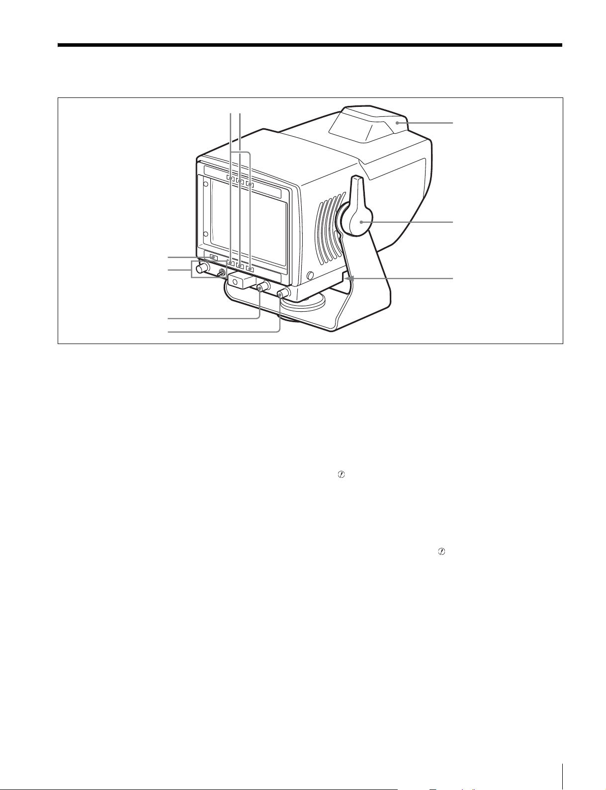
Functions of Parts and Controls
6
12
9
8
7
3
4
5
a R TALLY lamp (red)
Lights when the red tally signal is input.
b G TALLY lamp (green)
Lights when the green tally signal is input.
c Up-tally lamp (red)
The supplied number plate can be attached to this.
Set TALLY ON/OFF switch to ON. The lamp lights in
the same way as the R TALLY lamp.
d Tilt lock lever
Fixes any tilting position.
e 20-pin connector
Connect to a camera’s VF connector, using the supplied
connecting cable.
Power and video/tally signals are supplied through this
connector.
f CONTRAST knob
1)
Adjusts the contrast of the viewfinder picture.
To make adjustments, set the PEAKING switch to either
LOW (low frequency peaking) or HIGH (high frequency
peaking). Select either LOW or HIGH, whichever is
easier for focusing the lens.
Then, use the PEAKING knob to sharpen the edges in the
picture. Turning the PEAKING knob clockwise adjusts
the sharpness of the edges in the picture.
When not adjusting, set the PEAKING switch to OFF.
i (attention) indicator
This indicator lights up in orange when the camera detects
certain conditions. The particular conditions which cause
the indicator to light up are set up by the camera.
For information on how to set up and verify the
conditions under which the indicator will light, refer to
the manual for the camera being used.
1)
These controls do not affect the output signal of the camera.
g BRIGHT knob
1)
Adjusts the brightness of the viewfinder picture.
h PEAKING switch and knob
1)
Adjusts the sharpness of the picture.
Functions of Parts and Controls
15
Page 16
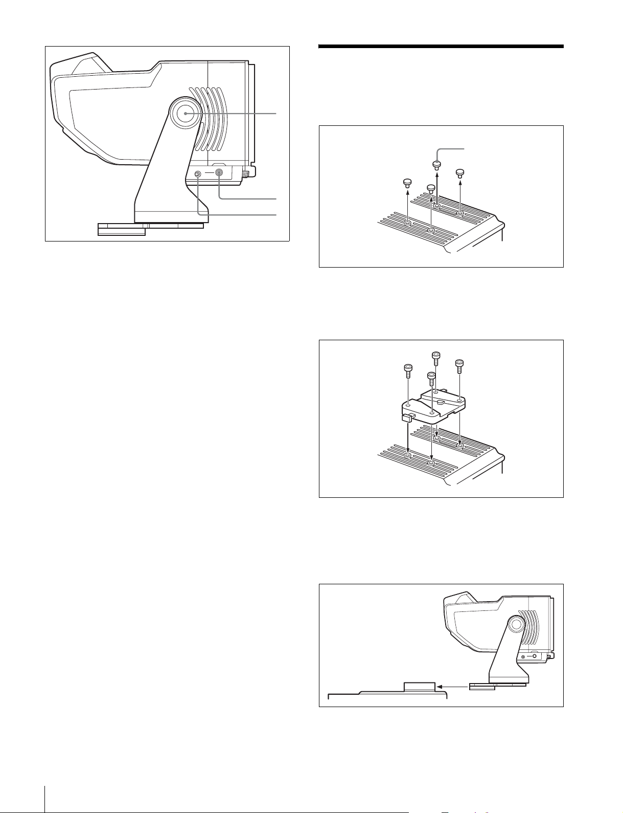
0
qa
qs
j Tilt knob
Adjusts the tilt friction.
k DIMMER knob
Adjusts the brightness of the up-tally lamp.
l TALLY ON/OFF switch
When this switch is set to ON, the up-tally lamp lights in
the same way as the R TALLY lamp.
Attaching to the Camera
1
Remove the four plastic caps from the camera.
Plastic caps
2
Attach the supplied V-wedge shoe attachment to the
camera using the supplied hexagonal wrench and four
hexagonal screws (4 ×12).
Attaching to the Camera
16
3
Mount this viewfinder firmly in the V-wedge shoe
attachment.
There is an audible click when the viewfinder snaps
into the attachment.
4
Detach the viewfinder from the camera.
Page 17
For the detaching, refer to the operation manual of the
camera.
5
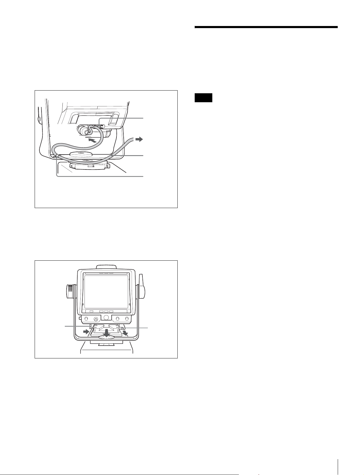
Connect the 20-pin connector to the camera’s VF
connector using the supplied connecting cable.
Clamp the supplied connecting cable with the two
clampers as shown in the following figure.
Clamp
Turning on the HDVF-550
When camera is turned on, power is supplied to the
HDVF-550.
The picture will be displayed several seconds after
turning on the camera.
Note
When the BRIGHT knob is turned fully
counterclockwise, no picture may appear in the
viewfinder.
To 20-pin
connector
1)
Depending on the position of the viewfinder, it may be
necessary to remove the connecting cable from the clamp.
To the
camera’s VF
connector
Connecting
cable
1)
Clamp
To detach the HDVF-550 from the camera
To detach the HDVF-550, pull the lever and push down
the button while pulling the viewfinder towards you, as
shown in the figure below.
Button
2
1
Lever
Turning on the HDVF-550
17
Page 18
Adjusting the Viewfinder
Tilt Adjustment
Position
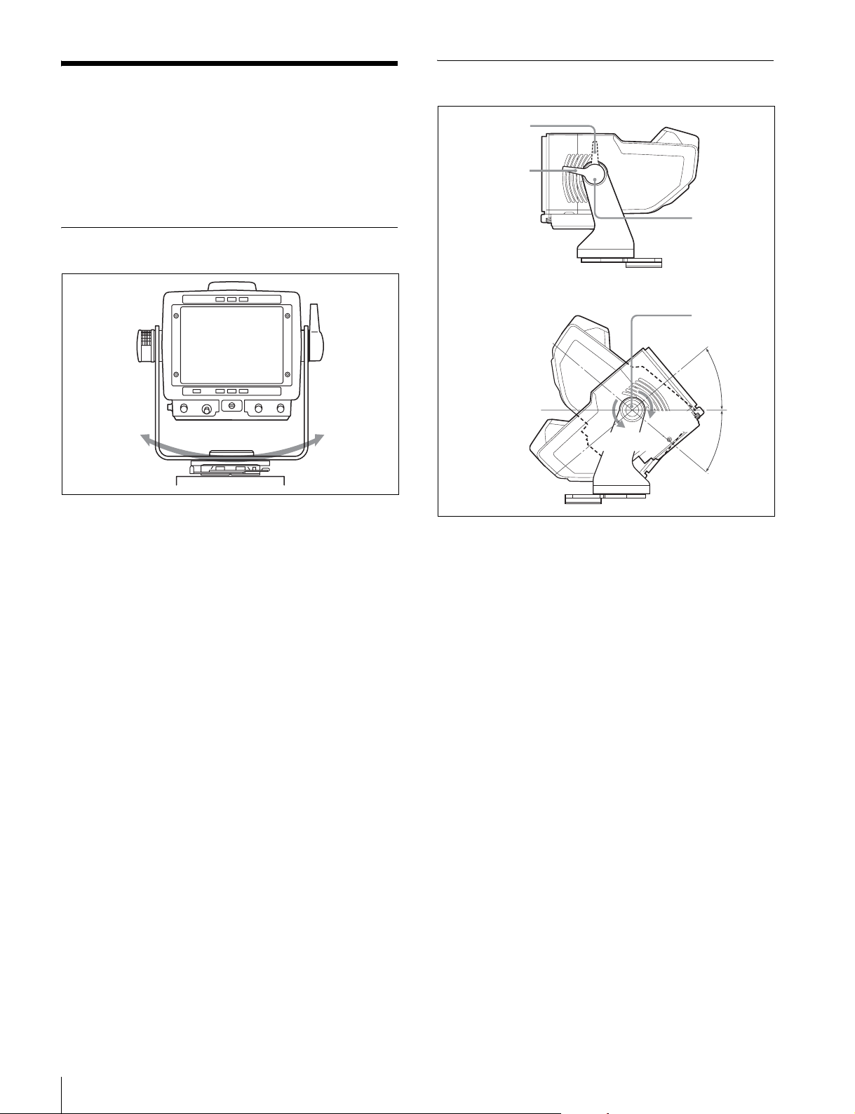
Use the HDVF-550 after adjusting the viewfinder
position as follows:
Panning Adjustment
180°
From the front-center position, you can rotate the
viewfinder (for panning) up to 90 degrees in the left and
right directions.
Lock position
Friction position
Tighten
Loosen
1
Set the tilt lock lever to the friction position.
Tilt lock lever
Tilt knob
40°
40°
2
Adjust the friction by turning the knob.
3
Adjust the tilt.
After setting the tilt position, set the tilt lock lever to
the lock position.
Adjusting the Viewfinder Position
18
Page 19
Attaching Accessories
Attaching a Hood
Attaching a Number Plate
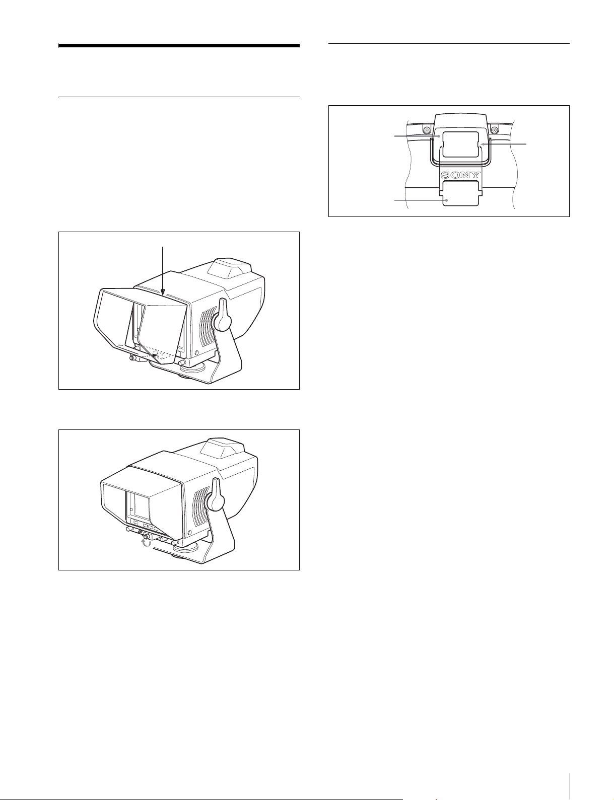
Insert the tabs on the sides of the number plate into each
slit in the up-tally lamp.
You can attach the VFH-550 in the same way as the
supplied studio monitor hood.
This section describes the procedure of attaching the
studio monitor hood.
1
To attach the hood, hook the upper part of the hood
over the projection on the top of the HDVF-550.
Projection
2
Tighten the screw to fix the HDVF-550.
Up-tally lamp
Number plate
Slit
1
Attaching Accessories
19
Page 20
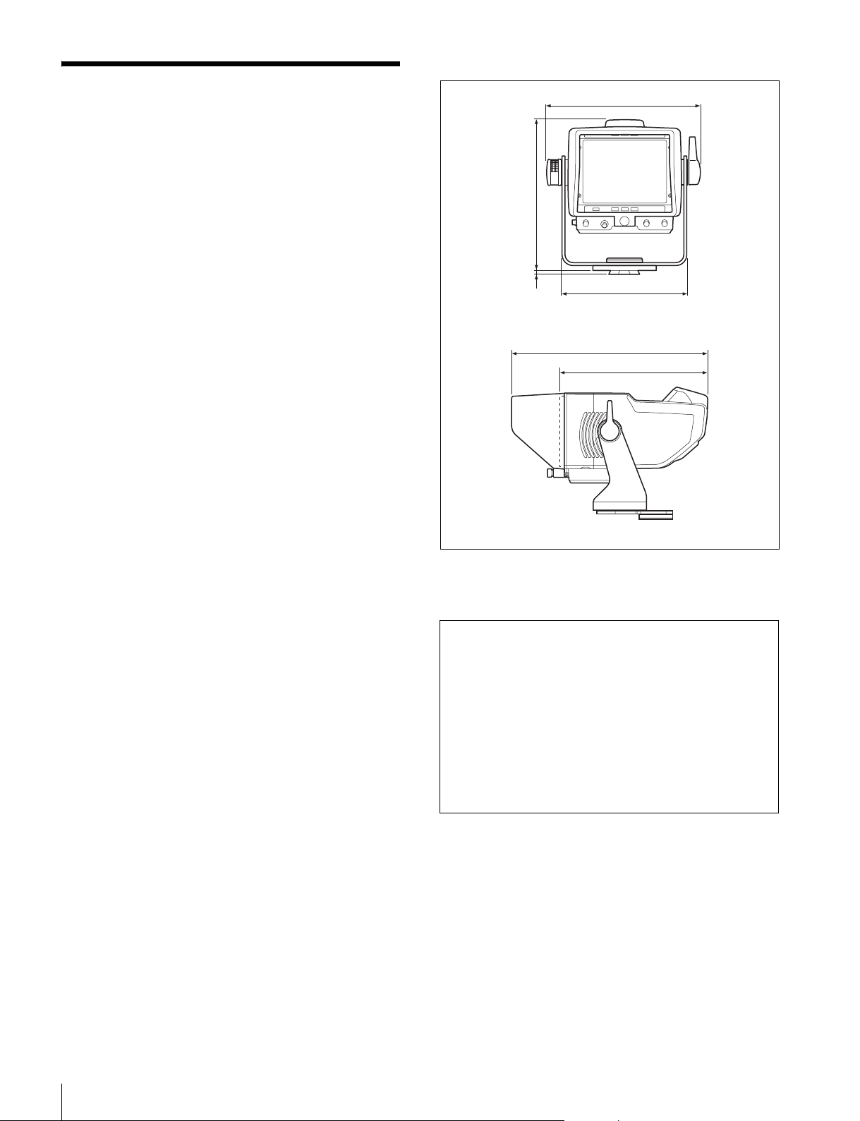
Dimensions
Specifications
CRT 5-type monochrome
Effective viewing area
16:9 mode: 96 × 54 mm (w/h)
Video signal Conforming to the BTA-S001 and
SMPTE-274M standards
Brightness 400 cd/m
Resolution More than 650 TV lines at center
More than 550 TV lines at corners
Input 20-pin connector
Video input: 1 Vp-p. Tri-level sync,
Frequency response
–3 dB or less (at 25 MHz)
Power requirements
10.5 V to 17 V DC, nominal 12 V DC
Power consumption
14 W
Operating temperature
–20°C to +45°C (–4°F to +113°F)
Storage temperature
–20°C to +60°C (–4°F to +140°F)
Operating humidity
0% to 90%, non-condensing
Mass Body: Approx. 2.3 kg (5 lb 1 oz)
Supplied accessories
V-wedge shoe attachment (1)
Hexagonal wrench (1)
Connecting cable (1)
Studio monitor hood (1)
Number plate (1)
Socket head cap screws (4)
Operation Manual (1)
Optional accessory
VFH-550 Outdoor Hood
Related accessory
HDC1500 Series HD Color Camera
2
75 ohms
(including the hood)
5
191 (7
/8)
/2)
1
188 (7
/4)
1
6 (
291 (11
156 (6
1
219 (8
/2)
1
/4)
5
/8)
unit: mm (inches)
Design and specifications are subject to change without
notice.
Note
Always verify that the unit is operating properly before
use. SONY WILL NOT BE LIABLE FOR DAMAGES
OF ANY KIND INCLUDING, BUT NOT LIMITED
TO, COMPENSATION OR REIMBURSEMENT ON
ACCOUNT OF THE LOSS OF PRESENT OR
PROSPECTIVE PROFITS DUE TO FAILURE OF
THIS UNIT, EITHER DURING THE WARRANTY
PERIOD OR AFTER EXPIRATION OF THE
WARRANTY, OR FOR ANY OTHER REASON
WHATSOEVER.
20
Specifications
Page 21

このマニュアルに記載されている事柄の著作権は当社にあ
り、説明内容は機器購入者の使用を目的としています。従っ
て、当社の許可なしに無断で複写したり、説明内容(操作、
保守等)と異なる目的で本マニュアルを使用することを禁止
します。
The material contained in this manual consists of information
that is the property of Sony Corporation and is intended solely
for use by the purchasers of the equipment described in this
manual.
Sony Corporation expressly prohibits the duplication of any
portion of this manual or the use thereof for any purpose other
than the operation or maintenance of the equipment
described in this manual without the express written
permission of Sony Corporation.
Page 22
HDVF-550 (SY)
4-121-991-01(1)
Sony Corporation
Printed in Japan
2008.10.13
© 2008
 Loading...