

Page 1
HD TRIAX CCU ADAPTOR
HDFX100
HD TRIAX CAMERA ADAPTOR
HDTX100
*3 - 903 - 897 - 04*
(1)
電気製品は、安全のための注意事項を守らないと、
火災や人身事故になることがあります。
このオペレーションマニュアルには、事故を防ぐための重要な注意事項と製品
の取り扱いかたを示してあります。このオペレーションマニュアルをよくお読
みのうえ、製品を安全にお使いください。お読みになったあとは、いつでも見ら
れるところに必ず保管してください。
OPERATION MANUAL [Japanese/English]
1st Edition (Revised 3)
Page 2
安全のために
ソニー製品は安全に十分に配慮して設計されています。しかし、電気製品はまちがっ
た使い方をすると、火災や感電などにより死亡や大けがなど人身事故につながること
があり、危険です。
事故を防ぐために次のことを必ずお守りください。
安全のための注意事項を守る
4 ~ 7 ページの注意事項をよくお読みください。
定期点検を実施する
長期間安全に使用していただくために、定期点検を実施することをおすすめします。
点検の内容や費用については、ソニーのサービス担当者または営業担当者にご相談く
ださい。
故障したら使用を中止する
ソニーのサービス担当者または営業担当者にご連絡ください。
万一、異常が起きたら
b
異常な音、
におい、煙が
出たら
a 電源を切る。
b 電源コードや接続コードを抜く。
c ソニーのサービス担当者または営業担当者に修理を
依頼する。
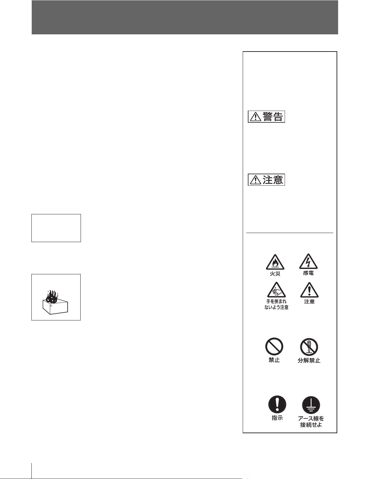
警告表示の意味
このオペレーションマニュアルお
よび製品では、次のような表示を
しています。表示の内容をよく理
解してから本文をお読みください。
この表示の注意事項を守らないと、
火災や感電などにより死亡や大け
がなど人身事故につながることが
あります。
この表示の注意事項を守らないと、
感電やその他の事故によりけがを
したり周辺の物品に損害を与えた
りすることがあります。
注意を促す記号
炎が出たら
b
すぐに電源を切り、消火する。
行為を禁止する記号
行為を指示する記号
2
Page 3
目次
警告 ...........................................................................................................................4
注意 ...........................................................................................................................5
その他の安全上のご注意...........................................................................................7
概要...........................................................................................................................7
HDFX100.......................................................................................................8
HDTX100 ......................................................................................................9
システム構成例.......................................................................................................10
光ファイバーケーブルとトライアックスケーブルを使った
延長システム....................................................................................10
使用上のご注意.......................................................................................................11
設置環境 ......................................................................................................11
コネクター・ケーブルのクリーニング........................................................11
仕様.........................................................................................................................13
HDFX100.....................................................................................................13
HDTX100 ....................................................................................................14
JP
3
Page 4
下記の注意を守らないと、 火災や感電によ
り死亡や大けがにつながることがあります。
油煙、湯気、湿気、ほこりの多い場所では設置・使用しない
上記のような場所で設置・使用すると、火災や感電の原因となります。
密閉環境には設置しない
空調管理されていない密閉環境に設置すると、内部に熱がこもり、火災の原因と
なることがあります。
ケーブルを傷つけたまま使用しない
ケーブルを傷つけたまま使用すると、火災や感電の原因となります。
光ファイバー / トライアックスケーブルは定期的に交換する
光ファイバーケーブルおよびトライアックスケーブルは、劣化したまま使用する
と火災や感電の原因となります。
定期的にケーブルを交換してください。
ラックの上部に設置しない(HDFX100 のみ)
本機は重量があります。ラックの上部に設置すると、ラックが転倒してけがの原
因となることがあります。ラックの下からの高さがおよそ 1m 以内の位置に設置
してください。
付属の電源コードを使用する(HDFX100 のみ)
付属品以外の電源コードを使用すると、火災や感電の原因となります。
他の電源コードを使用する場合は、ソニーのサービス担当者または営業担当者に
ご相談ください。
電源コードのプラグおよびコネクターは突き当たるまで差し
込む(HDFX100 のみ)
まっすぐに突き当たるまで差し込まないと、火災や感電の原因となります。
表示された電源電圧で使用する(HDFX100 のみ)
機器に表示されたものと異なる電源電圧で使用すると、火災や感電の原因となり
ます。
4
Page 5
下記の注意を守らないと、 けがをしたり周辺の物品に
損害を与えることがあります。
外装を外さない、改造しない
外装を外したり、改造したりすると、感電の原因となります。
内部の調整や設定および点検を行う必要がある場合は、必ずサービストレーニン
グを受けた技術者にご依頼ください。
内部に水や異物を入れない
水や異物が入ると火災や感電の原因となります。
万一、水や異物が入ったときは、すぐに電源を切り、電源コードや接続コードを
抜いて、ソニーのサービス担当者または営業担当者にご相談ください。
指定以外の機器を接続しない
本マニュアルに記載している以外の機器を接続すると、火災や感電の原因となり
ます。(詳しくは 11 ページを参照)
指定の接続ケーブルを使用する
光ファイバーケーブルおよびトライアックスケーブルは、指定のケーブルメー
カーに加工をご依頼ください。指定どおりのものを使用しないと、火災や感電の
原因となります。
正しいインターフェースで接続する
CAMERA/HDTX 端子、HDCU 端子(HDFX100 の場合)、および CAMERA 端
子、HDCU/HDFX 端子(HDTX100 の場合)に外部機器を接続する場合、接続
時のインターフェースが正しくないと火災や感電の原因となります。これらの端
子への機器の接続はサービストレーニングを受けた技術者にご依頼ください。
通風孔をふさがない(HDFX100 のみ)
通風孔をふさぐと内部に熱がこもり、火災の原因となることがあります。
• 風通しの悪い、狭いところに押し込まない。
• 毛足の長いじゅうたんや布団の上に置かない。
• 布をかけない。
電源コードを傷つけない(HDFX100 のみ)
電源コードを傷つけると、火災や感電の原因となります。
• 電源コードを加工したり、傷つけたりしない。
• 重いものをのせたり、引っ張ったりしない。
• 熱器具に近づけたり、加熱したりしない。
• 電源コードを抜くときは、必ずプラグを持って抜く。
• ラックマウントするとき、レールにはさみ込まない。
万一、電源コードが傷んだら、ソニーのサービス担当者に交換をご依頼くださ
い。
5
Page 6
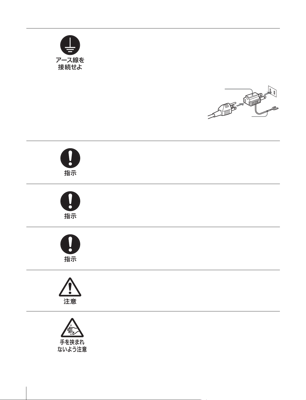
安全アースを接続する(HDFX100 のみ)
安全アースを接続しないと、感電の原因となることがあります。次の方法で
アースを接続してください。
・電源コンセントが
付属の電源コードを使用することで安全アースが接続されます。
・電源コンセントが
付属の 3極→2極変換プラグを使用し、
変換プラグから出ている緑色のアース線
を建物に備えられているアース端子に接
続してください。
安全アースを取り付けることができない場合は、ソニーのサービス担当者にご
連絡ください。
極の場合
3
極の場合
2
変換プラグ
アース線
機器を固定する(HDFX100 のみ)
地震などにより機器が転倒・落下すると、大けがの原因となります。インスト
レーションアンドメンテナンスマニュアルに従って機器をラックに固定してく
ださい。
ラックは転倒・移動防止の処理をする(HDFX100 のみ)
地震などによりラックが転倒・移動すると大けがの原因となります。また、
ラックの設置状況、強度を充分にお確かめください。
2人以上でラックマウント・運搬する(HDFX100 のみ)
本機は重量があるので、けがや事故を防ぐため、ラックマウントや運搬は必ず 2
人以上で行ってください。
安定した姿勢でラックマウントする(HDFX100 のみ)
本機をラックマウントするとき、および取り外すとき、バランスを崩すと機器
が落下してけがの原因となることがあります。安定した姿勢で注意深く作業し
てください。
ラックマウントアダプターに手や指をはさまない
(HDFX100 のみ)
ラックマウントした機器を収納するときおよび引き出すとき、ラックマウント
アダプターに手や指をはさみ、けがの原因となることがあります。
6
Page 7

その他の安全上のご注意
概要
設置上のご注意
• 設置時には、通気やサービス性を考慮して設置スペース
を確保してください。
- ファンの排気部や通気孔(底面)をふさがない。
- 通気のために、セット周辺に空間をあける。
- 作業エリアを確保するため、セット後方は、10cm 以上
の空間をあける。
レーザー機器についてのご注意
ここに規定した以外の手順による制御および調整は、危険
なレーザー放射の被爆をもたらします。
レーザー特性
波長 :1310±40nm
発振形態 :パルス変調
レーザー出力 :141 µW
+37
– 29
HD トライアックス CCU アダプターHDFX100/HD トラ
イアックスカメラアダプターHDTX100 は、ソニーの HD
カメラおよびカメラコントロールユニットと接続し、カメ
ラとカメラコントロールユニットの間の伝送を、光ファイ
バー伝送からトライアックス伝送へ変換するアダプターで
す。
HDFX100 は、トライアックスコネクターを持つ HD トラ
イアックスカメラアダプター HDTX100 と、光ファイバー
コネクターを持つカメラコントロールユニットとを結び、
伝送方式を変換します。
HDTX100 は、光ファイバーコネクターを持つ HD カメラ
と、トライアックスコネクターを持つ HD トライアックス
CCU アダプター HDFX100 とを結び、伝送方式を変換しま
す。
ラックマウント可能
HDFX100 は、19 インチの EIA 規格標準ラックに組み込む
ことができます。
高さは 3 ユニットです。
◆ ラックへの取り付けについては、ソニーのサービス担当者また
は営業担当者にお問い合わせください。
その他の安全上のご注意/概要
7
Page 8
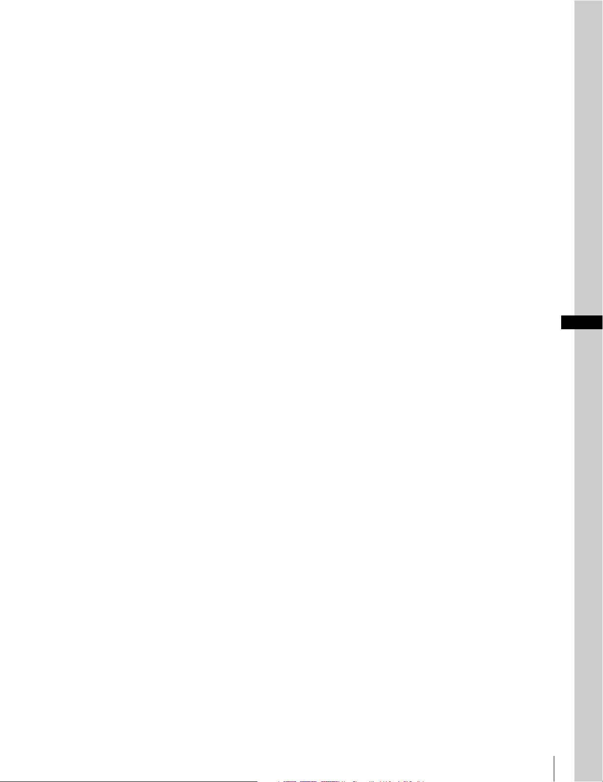
各部の名称と働き
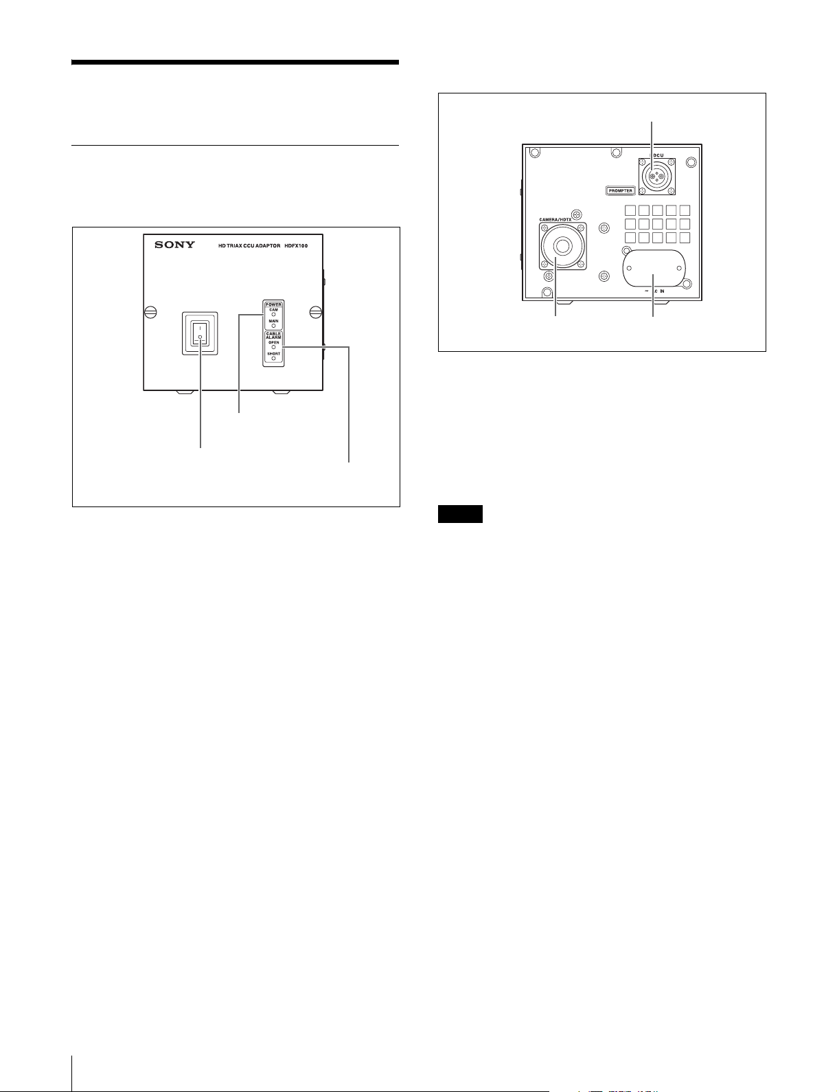
HDFX100
前面パネル
後面パネル
1
HDCU
端子
2
POWER
1 電源スイッチ
a 電源スイッチ
本機、ビデオカメラ、HD トライアックスカメラアダプ
ターなど、本システム全体の電源を入 / 切します。「|」
側を押すと電源が入り、「○」側を押すと電源が切れます。
b
POWER
本機の電源が入ると、MAIN インジケーターと CAM イン
ジケーターが点灯します。マスターセットアップユニット
やリモートコントロールパネルの CAMPOWER スイッチ
を押すと、カメラへの電源のみが OFF になり、CAM イン
ジケーターのみが消灯します。
c
CABLE ALARM
OPEN
OPEN
SHORT
(電源)インジケーター
(ケーブルアラーム)インジケーター
(赤): トライアックスケーブルを介して HD
トライアックスカメラアダプターが接
続されていないときに点灯します。
(赤点滅):後面の HDCU 端子に接続された HD カ
メラコントロールユニットからの光受
信の状態を表示します。異常があると
きは点滅します。早い点滅の場合は危
険レベル、遅い点滅は注意レベルの異
常を示します。
(赤): トライアックスケーブルの電源供給線
が外被シールドとショートしているか、
電源供給線間でショートしているとき
に点灯します。点灯中はカメラへ電源
が供給されません。
インジケーター
3
CABLE ALARM
インジケーター
2
CAMERA/HDTX
a
HDCU(HD
ファイバーコネクター)
光ファイバーケーブルで HD カメラコントロールユニット
と接続します。電源、コントロール信号、ビデオ信号、音
声信号など、ビデオカメラの信号を光ファイバーケーブル
1 本で送受信することができます。
ご注意
光ファイバーケーブルの接続端面にほこりなどが付着する
と、伝送エラーが発生しますので、接続しないときは、必
ず付属のキャップをはめてください。
b
CAMERA/HDTX
アダプター)端子(トライアックスコネクター)
トライアックスケーブルで HD トライアックスカメラ、ま
たは HD トライアックスカメラアダプター HDTX100 と接
続します。
c
AC IN(AC
付属の電源コードで AC 電源に接続します。付属のプラグ
ホルダーを使って、電源コードを本機に固定することがで
きます。
カメラコントロールユニット)端子(光
電源入力)端子
端子
(カメラ
3 〜
AC IN
トライアックスカメラ
/ HD
端子
8
各部の名称と働き
Page 9
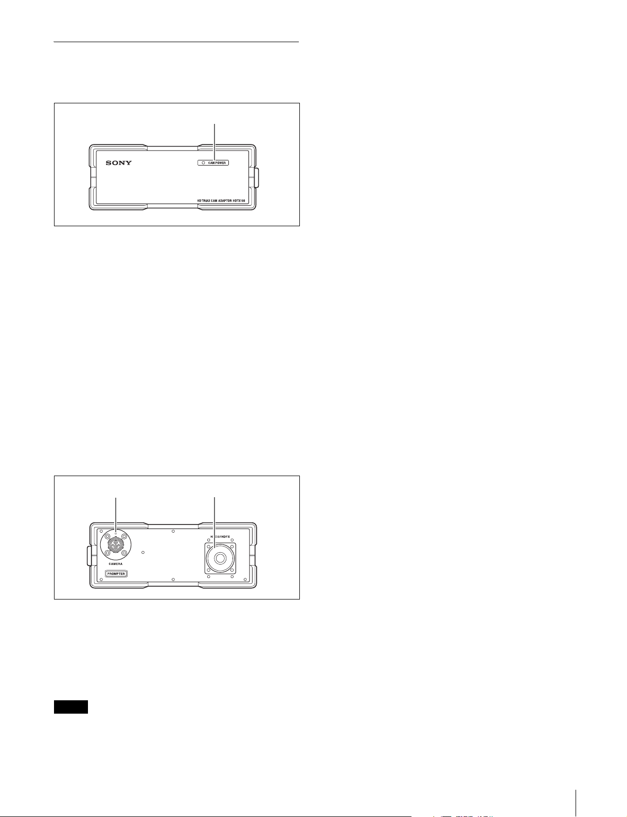
HDTX100
前面パネル
1
CAM POWER
インジケーター
b
HDCU/HDFX(HD
トライアックス
スコネクター)
トライアックスケーブルで HD トライアックス CCU アダ
プター HDFX100 と接続します。
カメラコントロールユニット
アダプター)端子(トライアック
CCU
/ HD
a
CAM POWER
ビデオカメラに電源が供給されているかどうかを示しま
す。
緑: ビデオカメラに電源が供給されているときに点灯
します。
赤: リモートコントロールパネル、マスターセット
アップユニット、HD カメラコントロールユニッ
トで CAMERAPOWER スイッチが OFF になっ
ているときに点灯します。
赤点滅: 後面の CAMERA 端子に接続されたビデオカメ
ラからの光受信の状態を示します。
早い点滅は危険レベルの異常を、遅い点滅は注意
レベルの異常を示します。
(カメラ電源)インジケーター
後面パネル
CAMERA
端子
2
HDCU/HDFX
端子1
a
CAMERA
光ファイバーケーブルでビデオカメラと接続します。電
源、コントロール信号、ビデオ信号、音声信号など、ビデ
オカメラの信号を光ファイバーケーブル 1 本で送受信する
ことができます。
ご注意
光ファイバーケーブルの接続端面にほこりなどが付着する
と、伝送エラーが発生しますので、接続しないときは、必
ず付属のキャップをはめてください。
(カメラ)端子(光ファイバーコネクター)
各部の名称と働き
9
Page 10
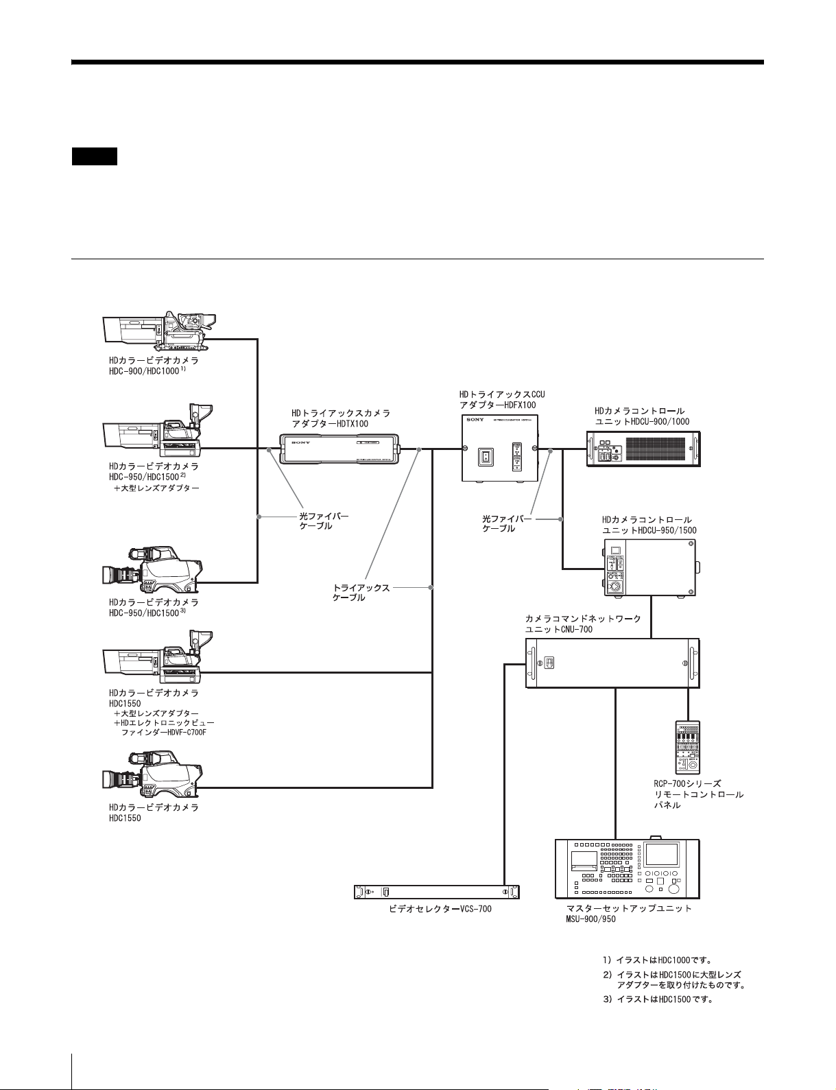
システム構成例
ご注意
・ 以下に記載されている周辺機器や関連機器は、「生産完
了」となっている場合があります。
機器の選定にあたっては、ソニーの営業担当者またはお
買い上げ店にお問い合わせください。
光ファイバーケーブルとトライアックスケーブルを使った延長システム
・ スキンゲート信号は、CameraVideo 信号に重畳され、
タリーが ON になると、強制的に OFF になります。
10
システム構成例
Page 11
ケーブルの延長距離について
HDFX100 および HDTX100 と接続して使用できるケーブ
ルの長さは、ケーブルの種類や接続する機器の組み合わせ
によって異なります。
光ファイバーケーブルの最大延長距離
HDTX100 と HD ビデオカメラの間に使用できる光ファイ
バーケーブルの長さは最大 3000m です(ポータブルカメ
ラ、ポータブルレンズ、2 インチビューファインダー使用
の場合)。
トライアックスケーブルの最大延長距離
HDFX100 と HDC1550、または HDFX100 と HDTX100 の
間に使用できるトライアックスケーブルの長さはケーブル
の種類によって異なります。ケーブルの種類ごとの最大延
長距離を次の表に示します。
ケーブルの種類 延長可能距離 プロンプター信号到達距離
φ
8.5 Fujikura
φ
14.5 Fujikura
Belden 9232
HDFX100
〜
〜
〜
700 m
1400 m
1050 m
50 m
100 m
75 m
からHDビデオカメラまでの最大延長距離
400 m
800 m
600 m
HDFX100 と HD ビデオカメラの間に使用できるケーブル
の長さは、接続する機種の組み合わせによって異なりま
す。
接続する機種ごとの最大延長距離を次の表に示します。な
お、表ではトライアックスケーブルに φ8.5Fujikura を使
用した場合の距離を示しています。
カメラ
HD
コントロールユニット
HDCU-900 HDC-900
ビデオ
HD
カメラ
HDC-950
+CA905L
HDC-950 HDVF-20A
使用する関連機器 距離
HDVF-9900
大型レンズ
HDVF-700A
大型レンズ
HDVF-C750W
大型レンズ
ポータブルレンズ
700 m
1)
1000 m
1)
1300 m
1)
3700 m
使用上のご注意
設置環境
本機は、次の条件に合う場所に設置してください。
・ 乾燥した通風の良い場所であること。
・ 高温の部屋や熱源の近くでないこと。
・ 強電界や強磁界の場所でないこと。
・ 太陽光線、強力ライトなどが直接あたらないこと。
コネクター・ケーブルのクリーニング
本機に光ファイバーケーブルを接続する際には、下記の光
コンタクト部をクリーニングしてから接続することを推奨
します。
・ HDFX100 の HDCU 端子
・ HDTX100 の CAMERA 端子
・ 光ファイバーケーブル
クリーニングは以下の手順で行ってください。
光コネクタークリーナー(市販品)が入手
可能な場合
必要な治工具
光コネクタークリーナー(市販品)
•
NTT-MECLETOP
(スティックタイプ)
・ クリーニング時、アルコール等は不要です。
・ この製品 1 本で 1 回の清掃が可能です。
クリーニング方法
凸コネクター
•
光コネクタークリーナーで、光コンタクト先端(白)を
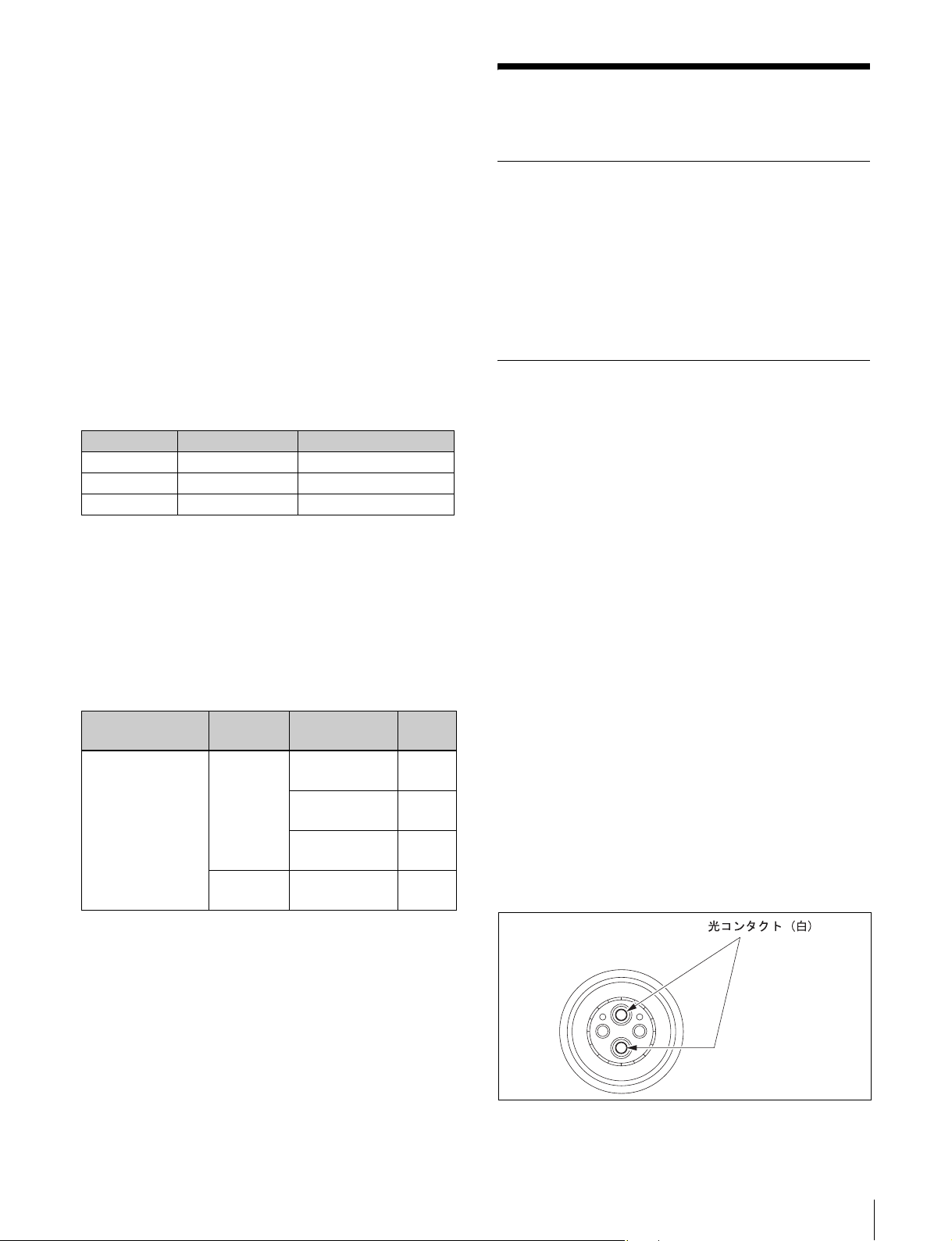
クリーニングしてください。
14100402 または 14100403 相当品
®
1)防振機構、高速サーボ搭載のレンズなど、大型レンズの
種類によっては消費電力が大きい(レンズ消費電流 2A
以上)ため、最大延長距離が短くなる場合があります。
使用上のご注意
11
Page 12
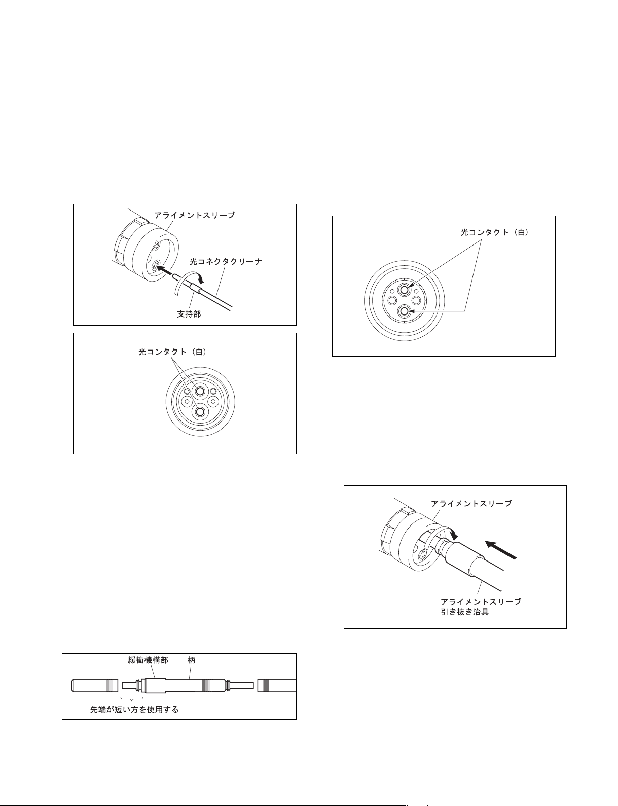
凹コネクター
•
1
光コネクタークリーナーをまっすぐ挿入する。
2
光コンタクトが押し下がる程度に押す。
(荷重 600g 〜 700g 程度)
3
光コンタクト先端に光コネクタークリーナーを押し付
けて、時計まわりに 4 〜 5 回転させる。
このとき、支持部付近を持って作業すると、荷重をか
けやすくなります。
綿棒(市販品)
•
綿棒は、直径 4mm 程度のものを使用してください。
5mm を超えると綿棒がコネクターの奥に十分に入らず、
光コンタクトの先端をクリーニングすることができませ
ん。
アルコール(市販品)
•
クリーニング方法
凸コネクター
•
アルコールを浸した綿棒で、光コンタクト先端(白)を
クリーニングしてください。
光コネクタークリーナー(市販品)が入手
できない場合
必要な治工具
アライメントスリーブ引き抜き治具
•
ター用)
ソニー J-6480-010-A またはレモジャパン(株)
DCC.91.312.5LA相当品
先端の短い方を使用してください。
この治具は緩衝機構部を備えています。使用時は緩衝機
構部を持たず、必ず柄の部分を持ってください。
HC-001
(凹コネク
凹コネクター
•
凹コネクターは光コンタクトがむき出しになっていませ
ん。あらかじめアライメントスリーブを外し、光コンタ
クトをむき出しにする必要があります。下記の手順で
行ってください。
1
アライメントスリーブ引き抜き治具をアライメントス
リーブにまっすぐ挿入し、時計方向に回す。
12
使用上のご注意
Page 13
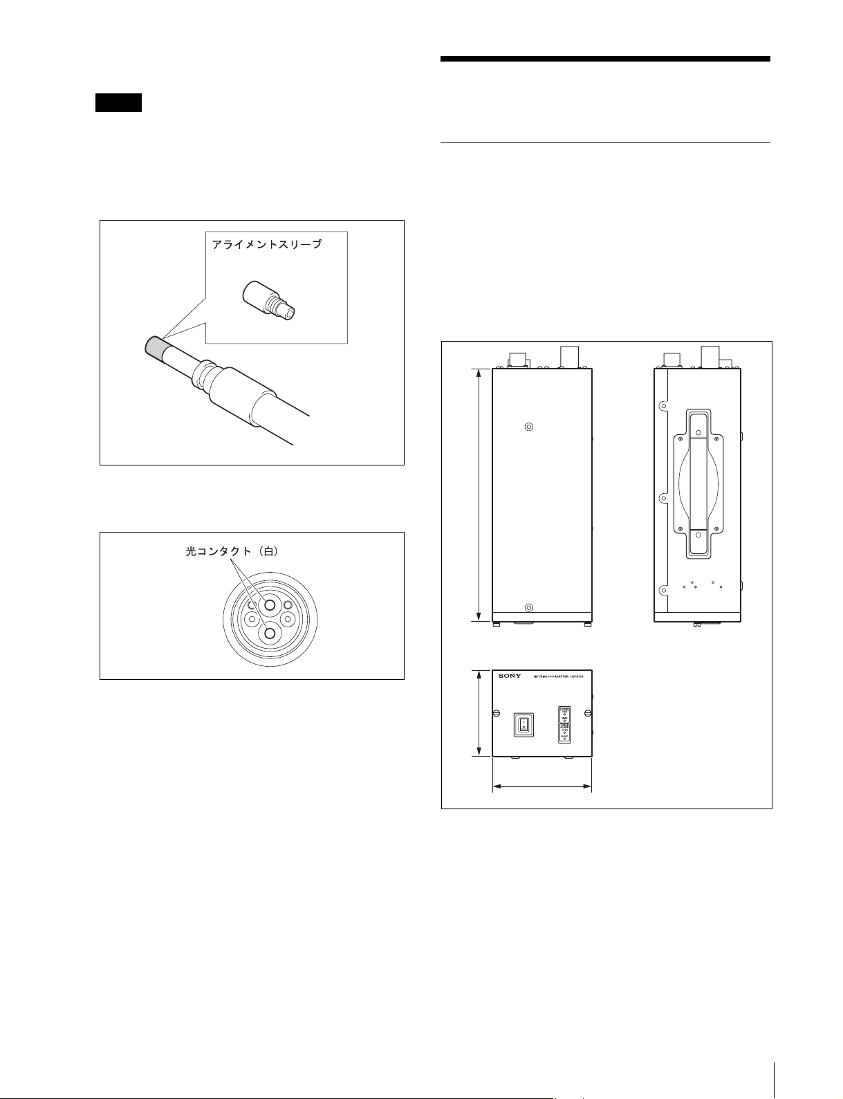
2
回転が止まったら、治具をまっすぐに強く引き抜く。
ご注意
治具の先端にアライメントスリーブがついたまま抜け
ますが、その状態のまま取り付けることができます。
アライメントスリーブを紛失したり、破損したりしな
いように充分注意してください。
(アライメントスリーブ:部品番号 9-980-074-01)
仕様
HDFX100
一般
電源 AC100 〜 240V、50/60Hz
消費電流 最大 3A
動作温度 + 5 ℃〜+ 40 ℃
保存温度 − 20 ℃〜+ 60 ℃
質量 約 5.5kg
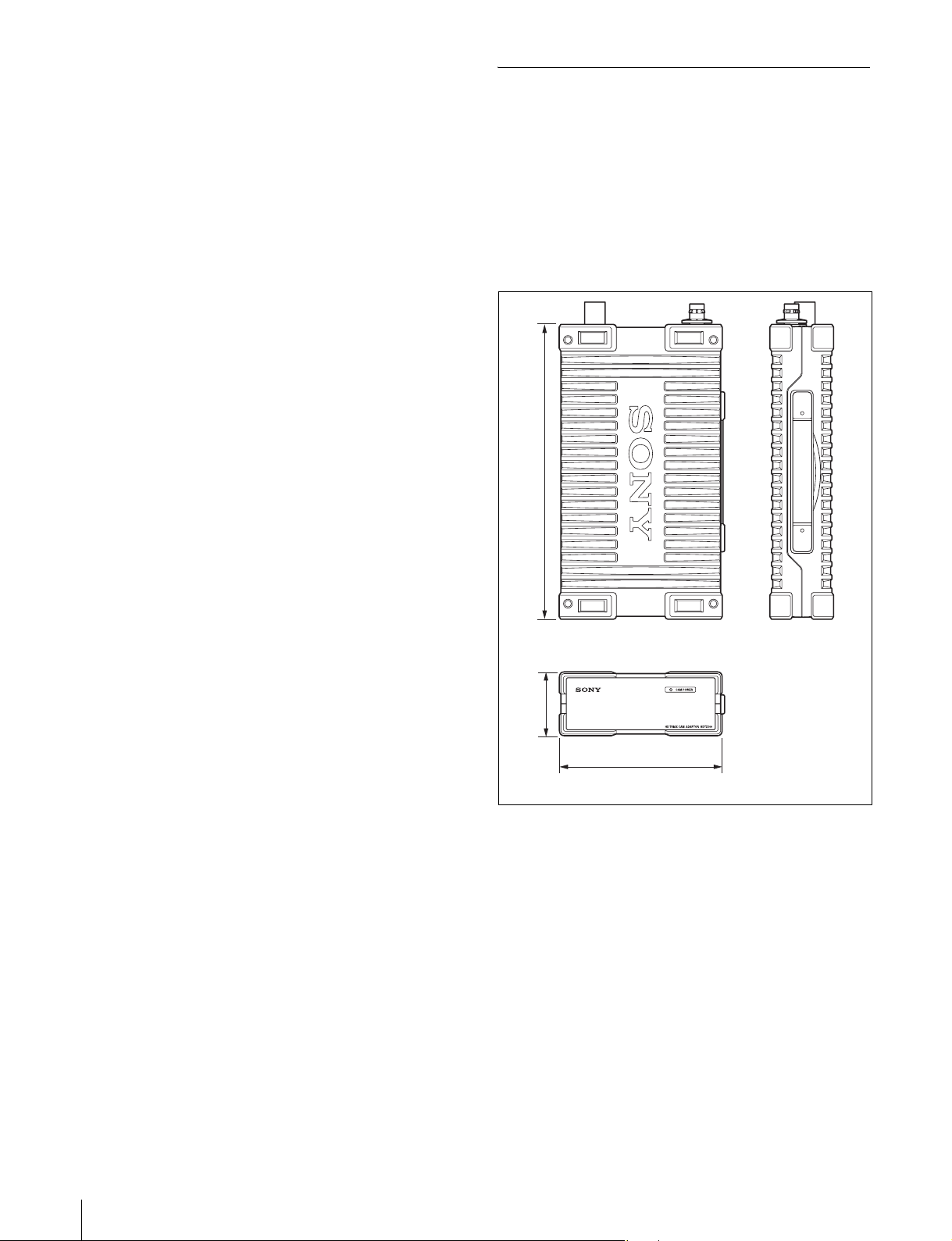
外形寸法図(単位:mm)
3
アルコールを浸した綿棒で、光コンタクト先端(白)
をクリーニングする。
4
アライメントスリーブが付いたままの治具を再び挿入
し、カチッと音がするまで押し込む。
5
治具を反時計方向に回してアライメントスリーブを取
り付け、治具を抜く。
365
124
145
入出力端子
CAMERA/HDTX
タジミ型トライアックスコネクター(1)
DC180V 給電
HDCU レモ型光 / 電気マルチコネクター(1)
1.485Gbps/1.4835GbpsSDI × 2
仕様
13
Page 14
入力端子
ACIN 1 系統、AC100 〜 240V
伝送信号
HDCU → CAMERA
・電源
・Audio(INCOM、PGM)
・RETVIDEO
・PrompterVideo
CAMERA → HDCU
・Audio(INCOM、MIC)
・CameraVideo
付属品
ネジB4 × 8(4)
AC 電源コード(1)
電源コード用プラグホルダー(1)
3 極→2 極変換プラグ(1)
オペレーションマニュアル(1)
本機は「高調波電流規格 JISC61000-3-2 適合品」です。
HDTX100
一般
電源 DC180V(HDFX100 より供給)
消費電流 最大 0.15A
動作温度 − 20 ℃〜+ 45 ℃
保存温度 − 20 ℃〜+ 60 ℃
質量 約 4.6kg
外形寸法図(単位:mm)
373
仕様および外観は、改良のため予告なく変更することがあ
りますがご了承ください。
81
206
入出力端子
CAMERA レモ型光 / 電気マルチコネクター(1)
1.485Gbps/1.4835GbpsSDI × 2
DC180V 給電
HDCU/HDFX タジミ型トライアックスコネクター(1)
伝送信号
HDCU → CAMERA
・電源
・Audio(INCOM、PGM)
・RETVIDEO
・PrompterVideo
14
仕様
Page 15

CAMERA → HDCU
・Audio(INCOM、MIC)
・CameraVideo
付属品
オペレーションマニュアル(1)
仕様および外観は、改良のため予告なく変更することがあ
りますがご了承ください。
仕様
15
Page 16
WARNING
To reduce the risk of fire or electric shock,
do not expose this apparatus to rain or
moisture.
To avoid electrical shock, do not open the
cabinet. Refer servicing to qualified
personnel only.
WARNUNG (Nur HDFX100)
DIESES GERÄT MUSS GEERDET WERDEN.
AVERTISSEMENT
Afin de réduire les risques d’incendie ou
d’électrocution, ne pas exposer cet
appareil à la pluie ou à l’humidité.
Afin d’écarter tout risque d’électrocution,
garder le coffret fermé. Ne confier
l’entretien de l’appareil qu’à un personnel
qualifié.
WARNUNG
Um die Gefahr von Bränden oder
elektrischen Schlägen zu verringern, darf
dieses Gerät nicht Regen oder Feuchtigkeit
ausgesetzt werden.
Um einen elektrischen Schlag zu
vermeiden, darf das Gehäuse nicht
geöffnet werden. Überlassen Sie
Wartungsarbeiten nur qualifiziertem
Fachpersonal.
This symbol is intended to alert the user to
the presence of important operating and
maintenance (servicing) instructions in
the literature accompanying the
appliance.
These HD Triax CCU Adaptor and HD Triax Camera
Adaptor are classified as CLASS 1 LASER PRODUCTS.
CAUTION
Use of controls or adjustments or performance of
procedures other than those specified herein may result in
hazardous radiation exposure.
Laser Diode Properties
Wave length: 1310 ±40 nm
Emission duration: Pulse Modulation
Laser output power: 141 µW
+37
–29
Daten der Laserdiode
Wellenlänge: 1310 ±40 nm
Emissionsdauer: Pulsmodulation
Laser-Ausgangsleistung: 141 µW
+37
–29
Laserdiode data
Bølgelængde: 1310 ±40 nm
Strålingsvarighed: Pulse Modulation
Lasereffekt: 141 µW
+37
–29
Laserdiodens egenskaper
Våglängd: 1310 ±40 nm
Strålningstid: Pulsmodulering
Laseruteffekt: 141 µW
+37
–29
Laserdiodens egenskaper
Bølgelengde: 1310 ±40 nm
Emisjonslengde: Pulsmodulasjon
Laser utgangseffekt: 141 µW
+37
–29
WARNING (HDFX100 only):
Using this unit at a voltage other than 120 V may require
the use of a different line cord or attachment plug, or both.
To reduce the risk of fire or electric shock, refer servicing
to qualified service personnel.
WARNING (HDFX100 only)
THIS APPARATUS MUST BE EARTHED.
AVERTISSEMENT (HDFX100 uniquement)
CET APPAREIL DOIT ÊTRE RELIÉ À LA TERRE.
16
CAUTION
The use of optical instruments with this product will
increase eye hazard.
Page 17
For the customers in the USA
This equipment has been tested and found to comply with
the limits for a Class A digital device, pursuant to Part 15
of the FCC Rules. These limits are designed to provide
reasonable protection against harmful interference when
the equipment is operated in a commercial environment.
This equipment generates, uses, and can radiate radio
frequency energy and, if not installed and used in
accordance with the instruction manual, may cause
harmful interference to radio communications. Operation
of this equipment in a residential area is likely to cause
harmful interference in which case the user will be
required to correct the interference at his own expense.
You are cautioned that any changes or modifications not
expressly approved in this manual could void your
authority to operate this equipment.
All interface cables used to connect peripherals must be
shielded in order to comply with the limits for a digital
device pursuant to Subpart B of Part 15 of FCC Rules.
Für Kunden in Europa
Dieses Produkt besitzt die CE-Kennzeichnung Und erfüllt
die EMV-Richtlinie (89/336/EWG) sowie die
Niederspannungsrichtlinie (73/23/EWG) der EGKommission.
Angewandte Normen:
• EN60950-1: Sicherheitsbestimmungen
• EN55103-1: Elektromagnetische Verträglichkeit
(Störaussendung)
• EN55103-2: Elektromagnetische Verträglichkeit
(Störfestigkeit),
für die folgenden elektromagnetischen Umgebungen:
E1 (Wohnbereich), E2 (kommerzieller und in
beschränktem Maße industrieller Bereich), E3
(Stadtbereich im Freien) und E4 (kontrollierter EMVBereich, z.B. Fernsehstudio).
For the customers in Europe
This product with the CE marking complies with both the
EMC Directive (89/336/EEC) and the Low Voltage
Directive (73/23/EEC) issued by the Commission of the
European Community.
Compliance with these directives implies conformity to
the following European standards:
• EN60950-1: Product Safety
• EN55103-1: Electromagnetic Interference (Emission)
• EN55103-2: Electromagnetic Susceptibility (Immunity)
This product is intended for use in the following
Electromagnetic Environment(s):
E1 (residential), E2 (commercial and light industrial), E3
(urban outdoors) and E4 (controlled EMC environment,
ex. TV studio).
Pour les clients européens
Ce produit portant la marque CE est conforme à la fois à la
Directive sur la compatibilité électromagnétique (EMC)
(89/336/CEE) et à la Directive sur les basses tensions (73/
23/CEE) émises par la Commission de la Communauté
Européenne.
La conformité à ces directives implique la conformité aux
normes européennes suivantes:
• EN60950-1: Sécurité des produits
• EN55103-1: Interférences électromagnétiques
(émission)
• EN55103-2: Sensibilité électromagnétique (immunité)
Ce produit est prévu pour être utilisé dans les
environnements électromagnétiques suivants:
E1 (résidentiel), E2 (commercial et industrie légère),
E3 (urbain extérieur) et E4 (environnement EMC contrôlé,
ex. studio de télévision).
GB
17
Page 18

Table of Contents
Overview ........................................................................................19
Locations and Functions of Parts ...............................................19
System Configuration Example...................................................22
Usage Precautions........................................................................23
Specifications................................................................................25
HDFX100 ........................................................................................... 19
HDTX100 ........................................................................................... 20
Extension system using optical fiber cable and Triax cable............... 22
Installation environment..................................................................... 23
Cleaning of connector/cable ............................................................... 23
HDFX100 ........................................................................................... 25
HDTX100 ........................................................................................... 27
18
Table of Contents
Page 19
Overview
The HD Triax CCU Adaptor HDFX100 and HD Triax
Camera Adaptor HDTX100 are designed for connection
between a Sony high-definition video camera and camera
control unit, to convert the link format between camera and
control unit from optical fiber to Triax.
The HDFX100 links the Triax connector of the HD Triax
Camera Adaptor HDTX100 to the optical fiber connector
of the Camera Control Unit, providing the required
conversion.
The HDTX100 links the optical fiber connector of the HD
camera to the Triax connector of the HD Triax Camera
Adaptor HDTX100, providing the required conversion.
Rack mount capable
The HDFX100 can be installed in a standard EIA 19-inch
rack (three units high).
Locations and Functions
of Parts
HDFX100
Front panel
2POWER indicators
For details on rack mounting, contact a Sony Service
representative or Sales representative.
1Power switch
3CABLE ALARM indicators
a Power switch
This switch controls power to the entire system including
the HDFX100, video camera, HD Triax Camera Adaptor,
etc. In the “|” position, power is on. In the “
power is off.
b POWER indicators
When power is turned on, the MAIN indicator and CAM
indicator light up. When the CAM POWER switch on the
Master Setup Unit or the Remote Control Panel is pressed,
only the camera power is turned off and the CAM indicator
goes out.
c CABLE ALARM indicators
OPEN (red): Lights up when the HD Triax
Camera Adaptor is not connected
via the Triax cable.
OPEN (flashing red):Shows the condition of optical
signal reception at the rear-panel
HDCU connector for the HD
Camera Control Unit. When there
is a problem, the indicator flashes.
Fast flashing indicates a hazardlevel problem, and slow flashing
indicates an alert-level problem.
SHORT (red): Lights up when one of the power
supply lines of the Triax cable is
shorted to the outer shield, or when
there is a short between the power
supply lines. While the indicator is
lit, the camera will not be powered.
a” position,
Overview / Locations and Functions of Parts
19
Page 20
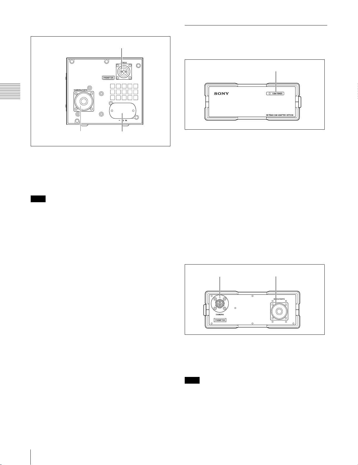
Rear panel
HDTX100
1HDCU connector
Front panel
1CAM POWER indicator
2CAMERA/HDTX connector
3AC IN connector
a HDCU (HD Camera Control Unit) connector
(optical fiber connector)
This is an optical fiber connector for the link to the HD
Camera Control Unit. Power, control signals, video
signals, audio signals etc. can be carried over a single link.
Note
When there is dust or other contamination on the
connection face for the optical fiber cable, transmission
errors will occur. Be sure to protect the connector with the
supplied cover when not in use.
b CAMERA/HDTX (Camera/HD Triax Camera
Adaptor) connector (Triax connector)
This is a Triax cable connector for the link to the HD Triax
Camera or HD Triax Camera Adaptor HDTX100.
c AC IN connector
Use the supplied power cord to connect this to an AC
outlet. The supplied plug holder can be used to fasten the
power cord to the unit.
a CAM POWER (camera power) indicator
Indicates the power supply status of the video camera.
Green: The indicator is lit in green when power is
being supplied to the video camera.
Red: The indicator is lit in red when the
CAMERA POWER switch at the Remote
Control Panel, Master Setup Unit, or HD
Camera Control Unit is set to OFF.
Flashing red: Shows the condition of optical signal
reception at the rear-panel CAMERA
connector for the video camera. When there
is a problem, the indicator flashes. Fast
flashing indicates a hazard-level problem,
and slow flashing indicates an alert-level
problem.
Rear panel
2HDCU/HDFX connector1CAMERA connector
20
Locations and Functions of Parts
a CAMERA connector (optical fiber connector)
This is an optical fiber connector for the link to the video
camera. Power, control signals, video signals, audio
signals etc. can be carried over a single link.
Note
When there is dust or other contamination on the
connection face for the optical fiber cable, transmission
errors will occur. Be sure to protect the connector with the
supplied cover when not in use.
Page 21

b HDCU/HDFX (HD Camera Control Unit/HD
Triax CCU Adaptor) connector(Triax connector)
This is a Triax cable connector for the link to the HD Triax
CCU Adaptor HDFX100.
Locations and Functions of Parts
21
Page 22
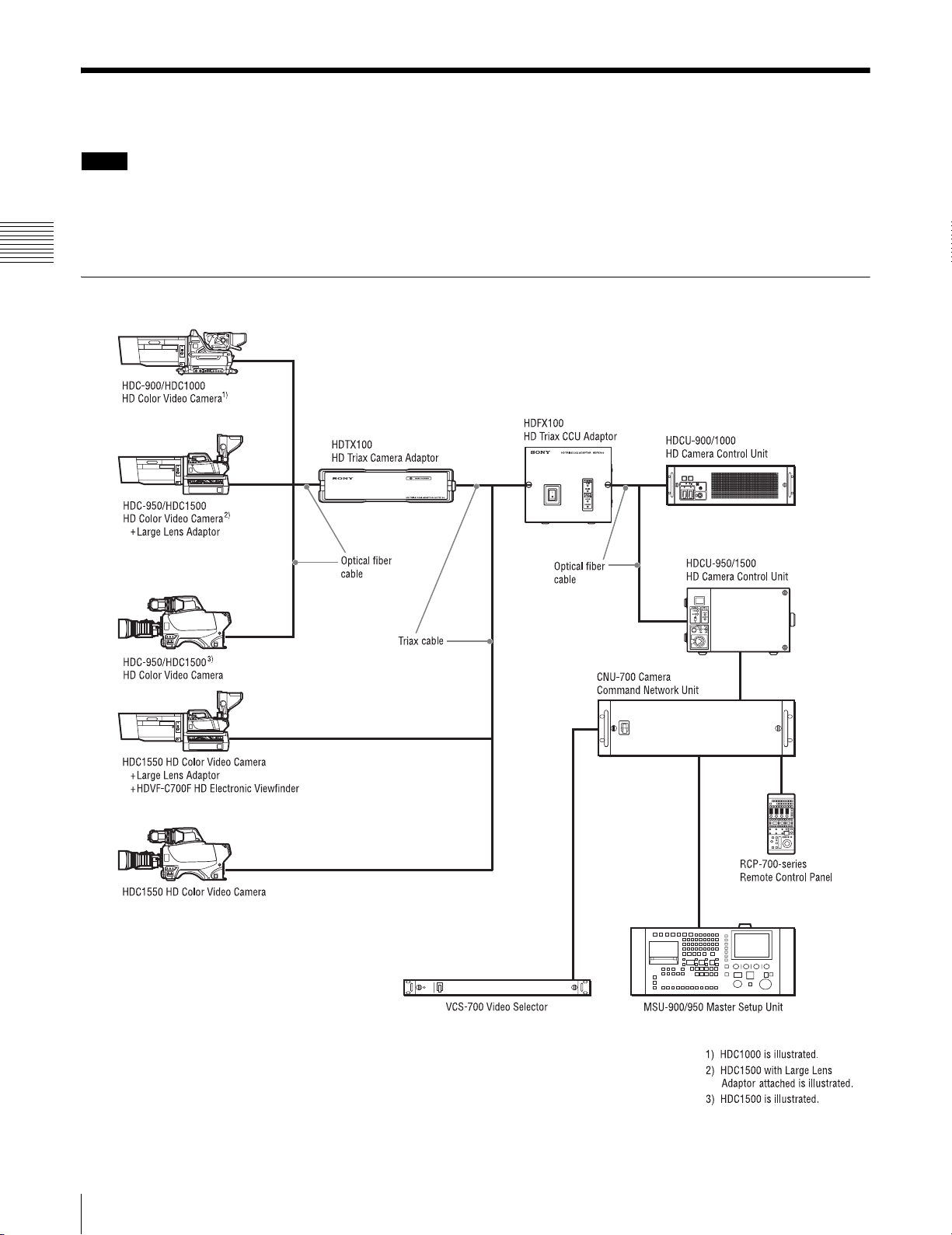
System Configuration Example
Notes
• Production of some of the peripherals and related
devices described below has been discontinued. For
advice about choosing devices, please contact your Sony
dealer or a Sony sales representative.
Extension system using optical fiber cable and Triax cable
• The skin gate signal is superimposed on the camera
video signal. When tally becomes ON, the skin gate
signal is forced to OFF.
22
System Configuration Example
Page 23
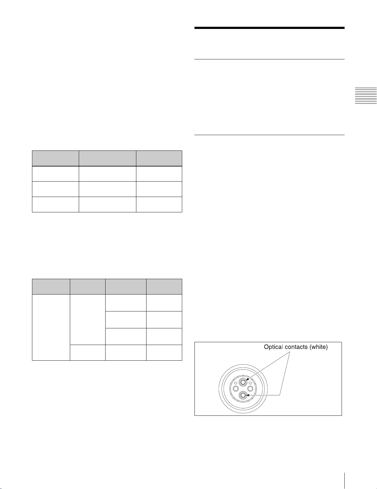
About cable extension length
The maximum allowable cable run when using the
HDFX100 and the HDTX100 depends on the cable type
and the combination of equipment.
Usage Precautions
Maximum cable run with optical fiber cable
The maximum optical fiber cable length between the
HDTX100 and the HD video camera is 3000 meters
(9840 feet) (when using a portable camera, portable lens,
and 2-inch viewfinder).
Maximum cable run with Triax cable
The maximum Triax cable length between the HDFX100
and the HDC1550 or between the HDFX100 and the
HDTX100 depends on the type of cable, as shown in the
table below.
Cable type Maximum extension
length
8.5 dia. Fujikura 50 – 700 meters
(160 – 2290 feet)
14.5 dia. Fujikura 100 – 1400 meters
(320 – 4590 feet)
Belden 9232 75 – 1050 meters
(240 – 3440 feet)
Prompter signal
range
400 meters
(1310 feet)
800 meters
(2620 feet)
600 meters
(1960 feet)
Maximum cable run between HDFX100 and HD
video camera
The maximum allowable cable run between the HDFX100
and the HD video camera depends on the combination of
equipment, as shown in the table below. The figures in the
table apply to the use of 8.5 dia. Fujikura Triax cable.
HD Camera
Control Unit
HDCU-900 HDC-900
HD video
camera
HDC-950
+ CA905L
HDC-950 HDVF-20A
Other
equipment
HDVF-9900
large lens
HDVF-700A
large lens
HDVF-C750W
large lens
portable lens
1)
1)
1)
Length
700 meters
(2290 feet)
1000 meters
(3280 feet)
1300 meters
(4260 feet)
3700 meters
(12130 feet)
Installation environment
Make sure that the installation environment fulfills the
following requirements:
• Dry and well ventilated
• Not subject to high temperatures or close to heat sources
• Not subject to strong electric or magnetic fields
• Not exposed to direct sunlight, strong lamps or similar
Cleaning of connector/cable
Before connecting an optical fiber cable to the unit, it is
recommended to clean the optical contacts on the
following parts:
• HDCU connector of HDFX100
• CAMERA connector of HDTX100
• Optical fiber cable
The steps for cleaning are described below.
When an optical connector cleaner (sold
separately) is available
Tools required
• Optical connector cleaner (commercially
available)
Product name: NTT-ME CLETOP
14100403 or equivalent (stick type)
• Cleaning fluid, cleaning alcohol or similar are not
necessary during cleaning.
• Each cleaning stick should only be used once.
Cleaning procedure
• Male connector
Clean the optical contact tips (white) using the optical
connector cleaner.
14100402 or
®
1) Additional features on the large lens such as vibration
damping and high-speed servo may result in higher
current consumption (over 2 amperes) which will
reduce the maximum allowable cable run.
Usage Precautions
23
Page 24
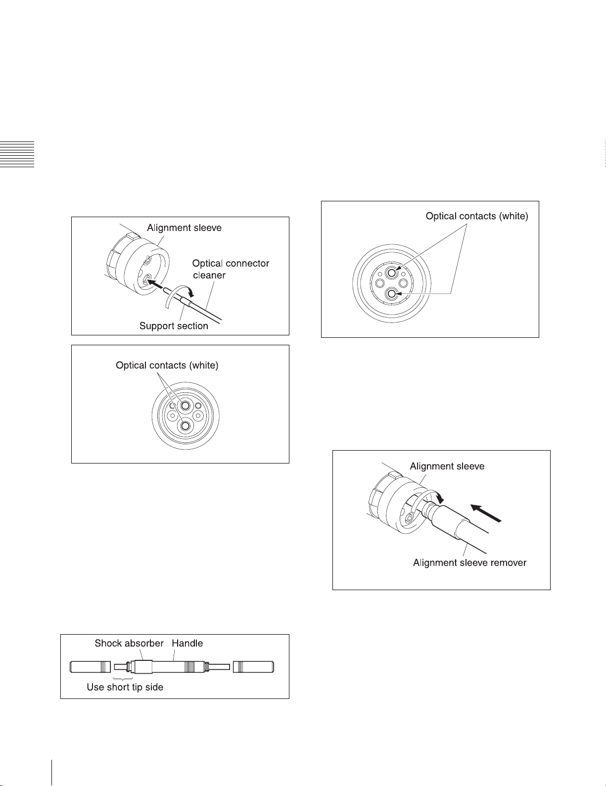
• Female connector
1
Insert the optical connector cleaner straight into the
connector.
2
Apply sufficient pressure (approximately 600 g to
700 g (20 oz. to 25 oz.)) to slightly push down the
optical contact.
• Cotton swab (commercially available)
Use cotton swabs with a diameter of about 4 mm (5/32
inches). If the diameter of the cotton swab exceeds
5 mm (7/32 inches), the swab will not fit fully into the
connector and the tip of the optical contact cannot be
cleaned.
• Cleaning alcohol (commercially available)
3
While pressing the optical connector cleaner against
the tip of the optical contact, rotate it clockwise four
or five times.
Grasping the support section of the optical connector
cleaner makes it easier to apply pressure.
Cleaning procedure
• Male connector
Clean the optical contact tips (white) using a cotton swab
moistened with alcohol.
• Female connector
The optical contacts of a female connector are not
accessible in the normal condition. To access the
contacts for cleaning, you must first remove the
alignment sleeve as described below.
1
Insert the alignment sleeve remover straight into the
alignment sleeve, and rotate it clockwise.
When an optical connector cleaner (sold
separately) is not available
Tools required
• Alignment sleeve remover HC-001 (for female
connector)
Sony J-6480-010-A
Use the short tip side of the tool.
The tool is equipped with a shock absorber. When using
the tool, always grasp the handle, not the shock absorber.
24
Usage Precautions
Page 25
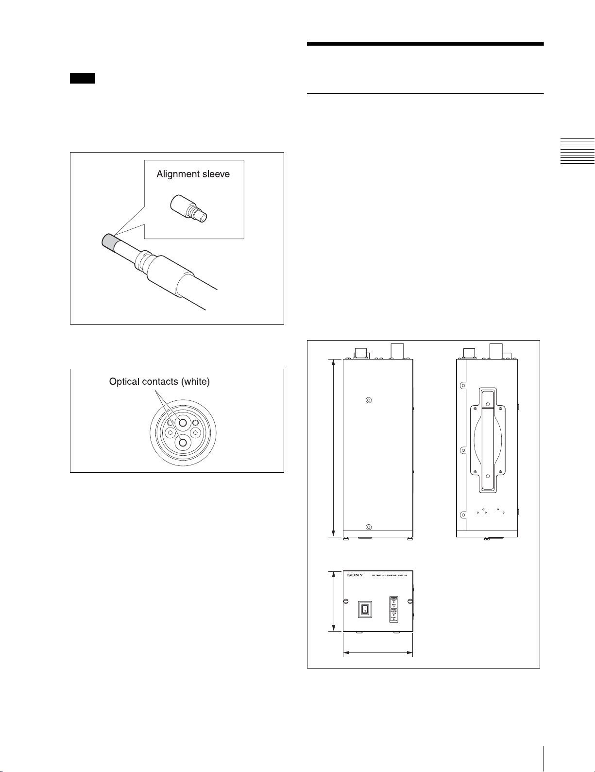
2
When the remover can no longer be turned, pull it out
straight.
Note
The alignment sleeve can be removed and installed
again while attached to the tip of the alignment sleeve
remover. Take care not to lose or damage the
alignment sleeve.
(Alignment sleeve part number: 9-980-074-01)
3
Clean the optical contact tips (white) using a cotton
swab moistened with alcohol.
Specifications
HDFX100
General
Power supply 100 to 240 V AC, 50/60 Hz
Current consumption
3 A max.
Peak inrush current
(1) Power ON, current probe method:
35 A (240 V)
(2) Hot switching inrush current,
measured in accordance with
European standard EN55103-1:
16 A (230 V)
Operating temperature
+5 °C to +40 °C (+41 °F to +104 °F)
Storage temperature
–20 °C to +60 °C (–4 °F to +140 °F)
Mass approx. 5.5 kg (12 lb. 2 oz.)
Dimensional drawing (unit: mm/inches)
4
Reinsert the alignment sleeve remover with the
attached alignment sleeve into the connector and push
it in until you hear a click.
5
Rotate the alignment sleeve remover
counterclockwise to fasten the alignment sleeve. Then
pull out the alignment sleeve remover.
8
/
3
365 / 14
124 / 5
3
145 / 5
/
4
Specifications
25
Page 26

Input/output connectors
CAMERA/HDTX
• For customers in the USA and Canada
King Triax connector (1)
• For customers in the European
countries
Fischer Triax connector (1)
180 V DC power supply
HDCU Lemo optical/electrical multi-connector
(1)
1.485 Gbps/1.4835 Gbps SDI × 2
Input connector
AC IN 100 - 240 V AC connector (1)
Signals carried
HDCU ➝ CAMERA
•Power
• Audio (INCOM, PGM)
• RET VIDEO
•Prompter Video
CAMERA ➝ HDCU
• Audio (INCOM, MIC)
• Camera Video
Précaution concernant le câble optique/électrique
composite:
Pour la connexion entre l’unité de commande de caméra
HD et une caméra, utilisez un câble optique/électrique
composite avec connecteurs spécifiés dans ce manuel pour
assurer la conformité avec la réglementation EMC.
Anschlüsse für optische/elektrische FBAS-Kabel:
• LEMO
PUW.3K.93C.TLCC96
®
(an „CAMERA“-Anschluss an der HDKamerasteuereinheit)
• LEMO
FUW.3K.93C.TLMC96
®
(an „HDCU“-Anschluss an der KAMERA)
Vorsichtsmaßregeln für optische/elektrische
FBASKabel:
Für Verbindung zwischen HD-Kamerasteuereinheit und
Kamera verwenden Sie immer ein optisches/elektrisches
FBAS-Kabel mit Steckern, wie in dieser Anleitung
beschrieben, um die Grenzwerte der geltenden EMVVorschriften zu erfüllen.
Design and specifications are subject to change without
notice.
Supplied accessories
B4 × 8 screw (8)
AC power cord (1)
AC power cord plug holder (1)
Operation manual (1)
Connectors for optical/electric composite cables:
•LEMO
(to the “CAMERA” connector on HDCU)
•LEMO
(to the “HDCU” connector on CAMERA)
Caution on the optical/electric composite cable:
For connection between the HD camera control unit and a
camera, be sure to use an optical/electric signal composite
cable with the connectors specified in this manual in order
to comply with the limit for EMC regulations.
Connecteurs pour les câbles optiques/électriques
composites:
•LEMO
(au connecteur « CAMERA » de l’unité de commande
de caméra HD)
•LEMO
(au connecteur « HDCU » de la caméra)
PUW.3K.93C.TLCC96
®
FUW.3K.93C.TLMC96
®
PUW.3K.93C.TLCC96
®
FUW.3K.93C.TLMC96
®
26
Specifications
Page 27
HDTX100
General
Power supply 180 V DC (supplied from HDFX100)
Current consumption
0.15 A max.
Operating temperature
–20 °C to +45 °C (–4 °F to +113 °F)
Storage temperature
–20 °C to +60 °C (–4 °F to +140 °F)
Mass approx. 4.6 kg (10 lb. 2 oz.)
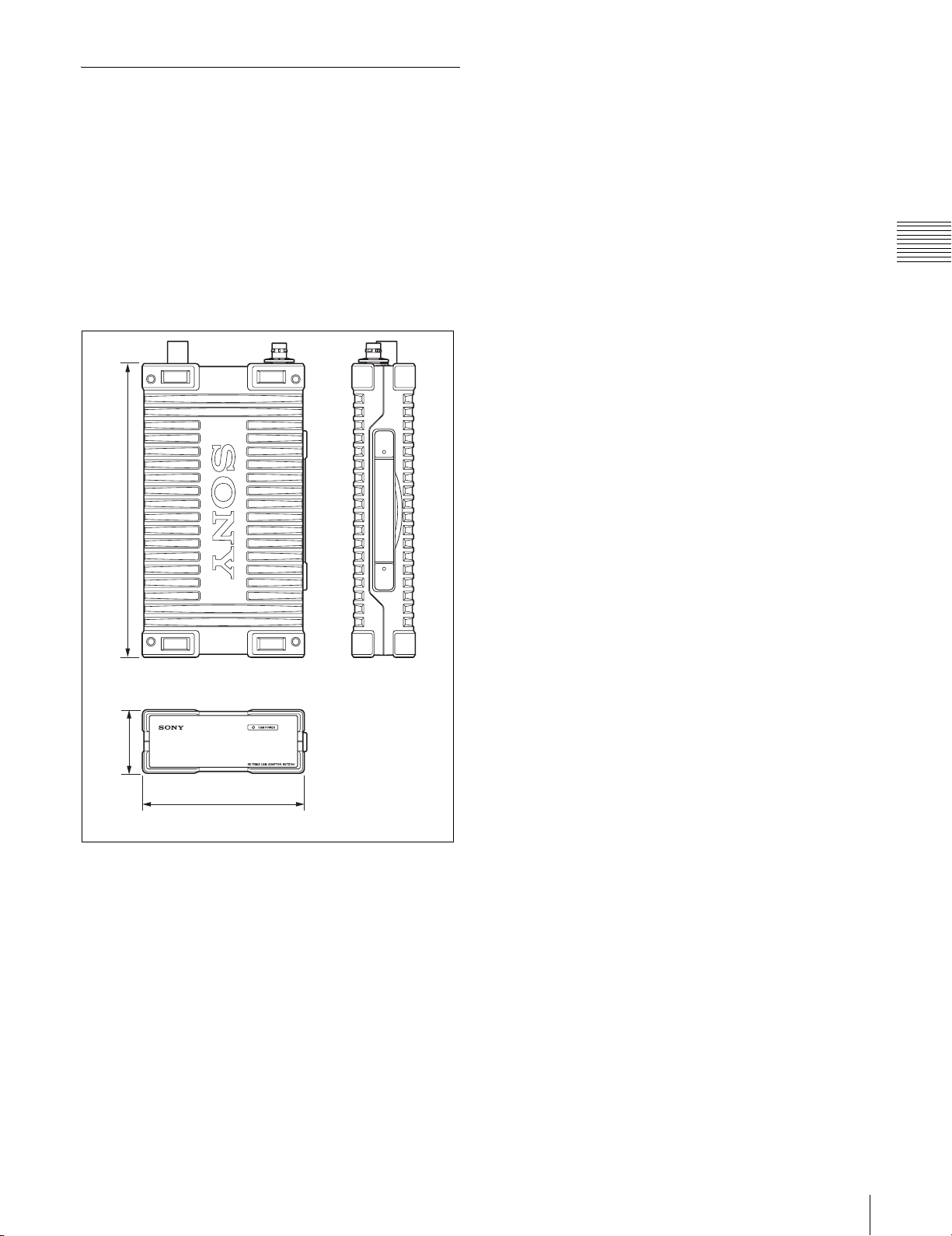
Dimensional drawing (unit: mm/inches)
4
/
3
373 / 14
Signals carried
HDCU ➝ CAMERA
•Power
• Audio (INCOM, PGM)
• RET VIDEO
•Prompter Video
CAMERA ➝ HDCU
• Audio (INCOM, MIC)
• Camera Video
Supplied accessories
Operation manual (1)
Connectors for optical/electric composite cables:
• LEMO
(to the “CAMERA” connector on HDCU)
• LEMO
(to the “HDCU” connector on CAMERA)
Caution on the optical/electric composite cable:
For connection between the HD camera control unit and a
camera, be sure to use an optical/electric signal composite
cable with the connectors specified in this manual in order
to comply with the limit for EMC regulations.
PUW.3K.93C.TLCC96
®
FUW.3K.93C.TLMC96
®
4
/
1
81 / 3
1
206 / 8
/
8
Input/output connectors
CAMERA Lemo optical/electrical multi-connector
(1)
1.485 Gbps/1.4835 Gbps SDI × 2
180 V DC power supply
HDCU • For customers in the USA and Canada
King Triax connector (1)
• For customers in the European
countries
Fischer Triax connector (1)
Connecteurs pour les câbles optiques/électriques
composites:
• LEMO
PUW.3K.93C.TLCC96
®
(au connecteur « CAMERA » de l’unité de commande
de caméra HD)
• LEMO
FUW.3K.93C.TLMC96
®
(au connecteur « HDCU » de la caméra)
Précaution concernant le câble optique/électrique
composite:
Pour la connexion entre l’unité de commande de caméra
HD et une caméra, utilisez un câble optique/électrique
composite avec connecteurs spécifiés dans ce manuel pour
assurer la conformité avec la réglementation EMC.
Anschlüsse für optische/elektrische FBAS-Kabel:
• LEMO
PUW.3K.93C.TLCC96
®
(an „CAMERA“-Anschluss an der HDKamerasteuereinheit)
• LEMO
FUW.3K.93C.TLMC96
®
(an „HDCU“-Anschluss an der KAMERA)
Vorsichtsmaßregeln für optische/elektrische
FBASKabel:
Für Verbindung zwischen HD-Kamerasteuereinheit und
Kamera verwenden Sie immer ein optisches/elektrisches
FBAS-Kabel mit Steckern, wie in dieser Anleitung
beschrieben, um die Grenzwerte der geltenden EMVVorschriften zu erfüllen.
Design and specifications are subject to change without
notice.
Specifications
27
Page 28

Page 29

このマニュアルに記載されている事柄の著作権は当社にあ
り、説明内容は機器購入者の使用を目的としています。
従って、当社の許可なしに無断で複写したり、説明内容
(操作、保守等)と異なる目的で本マニュアルを使用するこ
とを禁止します。
The material contained in this manual consists of information
that is the property of Sony Corporation and is intended
solely for use by the purchasers of the equipment described
in this manual.
Sony Corporation expressly prohibits the duplication of any
portion of this manual or the use thereof for any purpose
other than the operation or maintenance of the equipment
described in this manual without the express written
permission of Sony Corporation.
Page 30
*3-9 03- 89 7-04*
(1)
HDFX100/HDTX100
3-903-897-04 (1)
Sony Corporation
Printed in Japan
2007.11.13
© 2005
 Loading...