

Sony HDPSM-10 Service manual
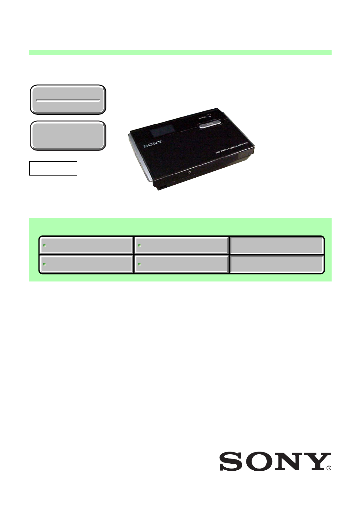
HDPS-M10
SERVICE MANUAL
Ver. 1.3 2007. 07
Revision History
Revision History
How to use
How to use
Acrobat Reader
Acrobat Reader
Revised-1
Replace the previously issued
SERVICE MANUAL 9-876-896-11
with this Manual.
HDPS-M10
US Model
Canadian Model
Europe Model
UK Model
Latin America Model
SMAP Model
Australian Model
New Zealand Model
Chinese Model
Hong Kong Model
Korea Model
Japanese Model
Link
Link
SPECIFICATIONS
SPECIFICATIONS
DISASSEMBLY
DISASSEMBLY
REPAIR PARTS LIST
REPAIR PARTS LIST
ADJUSTMENTS
ADJUSTMENTS
HDPS-M10
9-876-896-12
Sony EMCS Co.
HDD PHOTO STORAGE
2007G0800-1
©2007.07
Published by Kohda TEC

SPECIFICATIONS
Storage capacity
40 GB
(Formatted with FAT32. 1 GB amounts to
1,000,000,000 bytes.)
Media slots
“Memory Stick” slot × 1
CompactFlash slot × 1
Supported media
“Memory Stick” (“Memory Stick Duo”)
CompactFlash cards (CF cards)
(Type I, II, Microdrive)
Interface
USB 2.0 (Hi-Speed/Full-Speed)*
* If the connected computer does not support
USB 2.0, transfer speed will be according to
Full-speed USB (12 Mbps).
Connector
USB (mini-B) × 1
Power supply
Lithium-ion rechargeable battery
(internal)
100 - 240 V AC, 50/60 Hz
Dimensions
Approx. 135 × 30 × 92 mm
3
(5
/8 × 1 3/16 × 3 5/8 in.)
(W × H × D)
Mass
Approx. 300 g (10.6 oz.)
Supplied accessories
AC power adapter
(SONY, Model HDAC-M1/MCS-AC1) (1)
Carrying case (1)
Hand strap (1)
Indicator label (1)
Operating Instructions (this document)
PhotoDiary software (on the hard disk)
Power cord (1)
Read Me First (1)
USB cable (1)
Warranty card (1)
Design and specifications are subject to
change without notice.
Power consumption
7.5 W maximum
Ambient conditions
Operating temperature: 5°C to 40°C (40°F
to 104°F) (temperature gradient less than
10°C/hour (50°F/hour))
Operating humidity: 20% to 80%
(non-condensing)
HDPS-M10
— 2 —

SAFETY CHECK-OUT
After correcting the original service problem, perform the following
safety checks before releasing the set to the customer.
1. Check the area of your repair for unsoldered or poorly-soldered
connections. Check the entire board surface for solder splashes
and bridges.
2. Check the interboard wiring to ensure that no wires are
"pinched" or contact high-wattage resistors.
3. Look for unauthorized replacement parts, particularly
transistors, that were installed during a previous repair . Point
them out to the customer and recommend their replacement.
4. Look for parts which, through functioning, show obvious signs
of deterioration. Point them out to the customer and
recommend their replacement.
5. Check the B+ voltage to see it is at the values specified.
6. Flexible Circuit Board Repairing
• Keep the temperature of the soldering iron around 270˚C
during repairing.
• Do not touch the soldering iron on the same conductor of the
circuit board (within 3 times).
• Be careful not to apply force on the conductor when soldering
or unsoldering.
SAFETY-RELATED COMPONENT WARNING!!
COMPONENTS IDENTIFIED BY MARK 0 OR DOTTED LINE WITH
MARK 0 ON THE SCHEMATIC DIAGRAMS AND IN THE PARTS
LIST ARE CRITICAL TO SAFE OPERATION. REPLACE THESE
COMPONENTS WITH SONY PARTS WHOSE PART NUMBERS
APPEAR AS SHOWN IN THIS MANUAL OR IN SUPPLEMENTS
PUBLISHED BY SONY .
Unleaded solder
Boards requiring use of unleaded solder are printed with the leadfree mark (LF) indicating the solder contains no lead.
(Caution: Some printed circuit boards may not come printed with
the lead free mark due to their particular size.)
: LEAD FREE MARK
Unleaded solder has the following characteristics.
• Unleaded solder melts at a temperature about 40°C higher than
ordinary solder.
Ordinary soldering irons can be used but the iron tip has to be
applied to the solder joint for a slightly longer time.
Soldering irons using a temperature regulator should be set to
about 350°C.
Caution: The printed pattern (copper foil) may peel away if the
heated tip is applied for too long, so be careful!
• Strong viscosity
Unleaded solder is more viscous (sticky, less prone to flow) than
ordinary solder so use caution not to let solder bridges occur such
as on IC pins, etc.
• Usable with ordinary solder
It is best to use only unleaded solder but unleaded solder may
also be added to ordinary solder.
ATTENTION AU COMPOSANT AYANT RAPPORT
À LA SÉCURITÉ!
LES COMPOSANTS IDENTIFÉS P AR UNE MARQUE 0 SUR LES
DIAGRAMMES SCHÉMA TIQUES ET LA LISTE DES PIÈCES SONT
CRITIQUES POUR LA SÉCURITÉ DE FONCTIONNEMENT. NE
REMPLACER CES COMPOSANTS QUE PAR DES PIÈSES SONY
DONT LES NUMÉROS SONT DONNÉS DANS CE MANUEL OU
DANS LES SUPPÉMENTS PUBLIÉS PAR SONY.
CAUTION :
Danger of explosion if battery is incorrectly replaced.
Replace only with the same or equivalent type.
HDPS-M10
— 3 —

TABLE OF CONTENTS
1. DISASSEMBLY ·························································1-1
2. REPAIR PARTS LIST
2-1. EXPLODED VIEWS ······················································2-3
2-1-1.OVERALL SECTION·····················································2-3
2-1-2.TOP CASE SECTION ····················································2-4
2-1-3.PWB ASSEMBL Y···························································2-5
3. ADJUSTMENTS
3-1. PREPARATIONS BEFORE ADJUSTMENT·················3-1
3-1-1.List of Service Tools ························································3-1
3-1-2.Preparations ·····································································3-2
3-1-3.Order of Adjustments ······················································3-3
3-2. ADJUSTMENTS·····························································3-4
3-2-1.NTFS format····································································3-4
3-2-2.HDD Self Format ····························································3-4
3-2-3.Stand Alone Copy Check and Final Function
(USB Mode) Check ·························································3-5
3-2-3-1. Stand Alone Copy Check·········································3-5
3-2-3-2. Final Function (USB Mode) Check ·························3-5
3-2-3-2-1. Preparations ·····························································3-5
3-2-3-2-2. Final Function (USB Mode) Check ·························3-7
3-2-4. USB 1.1 Confirmation Check ·······································3-8
3-2-5. Final Function 2 (USB Mode) Check ···························3-8
3-2-6. Burn In (Read) Check ··················································· 3-9
3-2-7. Burn In (Write) Check ················································3-10
3-2-8. NTFS format ······························································· 3-11
3-2-9. HDD Self Format························································3-11
3-2-10. Photo Diary Software Download ································3-11
3-2-11. Firmware Upgrade ······················································3-12
3-2-11-1. Firmware Upgrade ·················································3-12
3-2-11-2. Language Settings··················································3-14
3-2-12. Full Charge Implementation ······································· 3-14
HDPS-M10
— 4 —
t
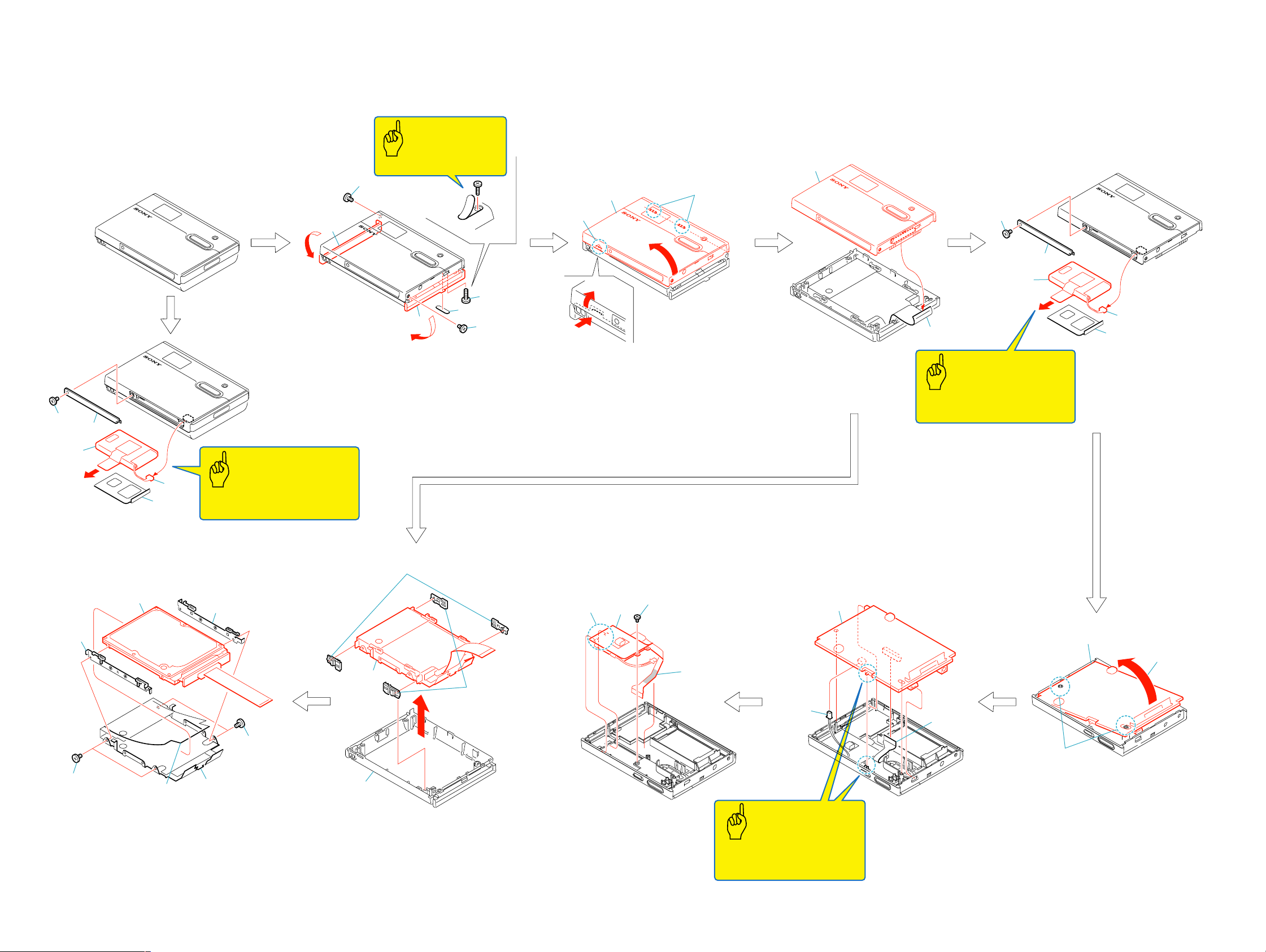
1-1. DISASSEMBLY
The following flow chart shows the disassembly procedure.
1. DISASSEMBLY
Caution
Note: The foot rubber
cannot be reused.
4
3
2
2
1
2
4
1
Screw (M2x3.5) black
2
Battery cover assembly
3
Connector
3
5
4
Battery assembly
5
Battery plate, Battery plate sheet
Note: Be sure to fully charge the
battery after the repair is completed.
Caution
3
b
a
1
Open the lid (R) assembly in the
direction of the arrow a.
2
Screw (M2x3.5) black
3
Open the lid (L) assembly in the
direction of the arrow b.
3
1
6
1
5
2
4
Screw (M2x3.5) black
5
Foot rubber
6
Tapping screw (M2x8) silver
1
Claw
2
Two claws
3
Open the top case sub assembly
in the direction of the arrow.
1
Flexible flat cable
2
Top case sub assembly
1
Caution
Note: Be sure to fully charge the
battery after the repair is completed.
1
2
4
3
5
1
Screw (M2x3.5) black
2
Battery cover assembly
3
Connector
4
Battery assembly
5
Battery plate, Battery plate shee
4
1
1
2
3
4
Two spacers A, B
HDPS-M10
7
3
Two screws (M3x4) silver
Two screws (M3x4) silver
Peel off the sheet.
Absorber bracket A,
5
2
6
5
Absorber bracket B,
Two spacers A, B
6
Bottom shield , etc
7
Hard disk drive, IOM-F2 board,
Flexible flat cable
2
1
2
1
4
3
3
1
2
4
1
1
Remove the hard disk drive, Bottom shield ,
etc in the direction of the arrow.
2
Two shock absorbers A
3
Two shock absorbers B
4
Bottom case assembly, Lid (R) assembly,
Lid (L) assembly
1
Tapping screw (M2x3) silver
2
T wo hooks
3
Peel off the adhesive side
of the flexible side.
4
LCD set assembly
Caution
Note: When installing the
PWB board, align the
switch position.
Connector
2
Flexible flat cable
3
PWB board
1-1 1-2E
3
1
2
1
Lift the PWB board out from the top
case assembly case.
2
Two positioning holes
3
Remove the PWB board
in the direction of the arrow.
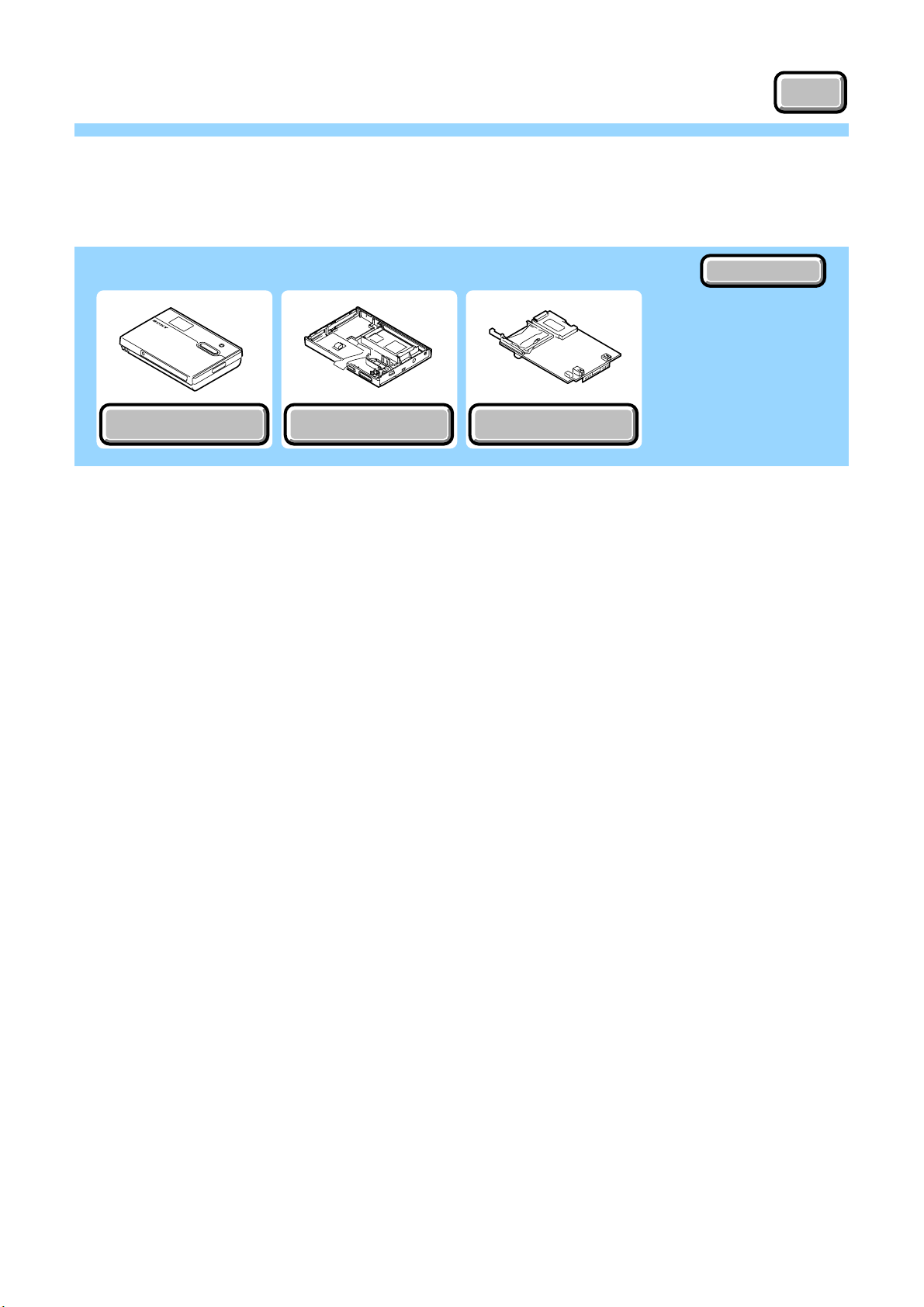
2. REPAIR PARTS LIST
OVERALL SECTION
OVERALL SECTION
NOTE
NOTE
Link
Link
EXPLODED VIEWS
EXPLODED VIEWS
TOP CASE SECTION
TOP CASE SECTION
PWB ASSEMBLY
PWB ASSEMBLY
ACCESSORIES
ACCESSORIES
HDPS-M10
2. REPAIR PARTS LIST
2. REPAIR PARTS LIST
NOTE:
• -XX, -X mean standardized parts, so they may have some differences from
the original one.
• Items marked “*” are not stocked since they are seldom required for routine
service. Some delay should be anticipated when ordering these items.
• The mechanical parts with no reference number in the exploded views are not
supplied.
• Due to standardization, replacements in the parts list may be different from
the parts specified in the diagrams or the components used on the set.
• CAPACITORS:
uF: µF
• COILS
uH: µH
• RESISTORS
All resistors are in ohms.
METAL: metal-film resistor
METAL OXIDE: Metal Oxide-film resistor
F: nonflammable
• SEMICONDUCTORS
In each case, u: µ, for example:
uA...: µA... , uPA... , µPA... ,
uPB... , µPB... , uPC... , µPC... ,
uPD..., µPD...
When indicating parts by reference number,
please include the board name.
The components identified by mark 0 or
dotted line with mark 0 are critical for safety.
Replace only with part number specified.
Les composants identifiés par une marque
0 sont critiques pour la sécurité.
Ne les remplacer que par une pièce portant
le numéro spécifié.
• Abbreviation
CND : Canadian model
AUS : Australian model
CH : Chinese model
HK : Hong Kong model
KR : Korea model
J : Japanese model
TW : Taiwan model
NZ : New Zealand model
SMAP : Sony Marketing Asia P acif ic model
LA : Latin America model
EU : Europe model
US : United States model
UK : United Kingdom model
HDPS-M10
2-1
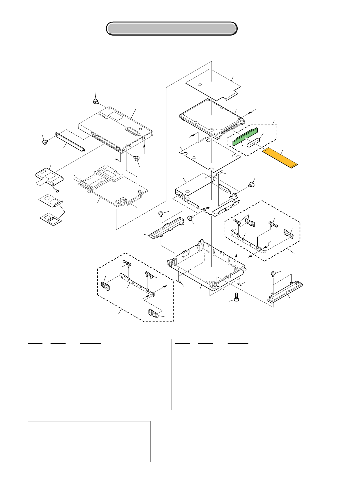
2-1. EXPLODED VIEWS
2-1-1. OVERALL SECTION
ns : not supplied
5
2. REPAIR PARTS LIST
2. REPAIR PARTS LIST
Top case section
(See page 2-4)
ns
6
C
7
5
D
ns
4
E
F
ns
CN201
8
3
5
16
ns
9
A
B
ns
9
ns
ns
ns
ns
(Note)
PWB assembly
(See page 2-5)
10
2
A
F
11
C
ns
ns
ns
B
ns
D
15
14
15
E
13
10
12
1
Ref. No. Part No. Description Ref. No. Part No. Description
1 A-1134-386-A ABSORBER ASSY SERVICE A
2 A-1133-812-A LID (L) ASSY
3 A-1133-873-A BATTERY ASSY (US,CND)
3 A-1146-128-A BATTERY ASSY
(LA UK, EU, AUS, NZ, HK, TW, KR, CH, SMAP)
3 A-1182-732-A BATTERY ASSY (J)
4 A-1133-816-A BATTERY COVER ASSY
5 2-108-513-01 SCREW PRECISION M2X3.5 (BLACK)
6 1-797-315-11 HDD (40GB, HTS424040M9AT00)
7 A-1133-897-A IOM-F2 BOARD, COMPLETE
Note :
When the TOP CASE ASSY SERVICE (Ref. No.52
on page 2-4) is going to be replaced by the TOP
CASE ASSY SERVICE with suffix-B, do not install
the two parts that are shown as “ns” (not supplied)
above.
ns
8 1-829-549-11 CABLE, FLEXIBLE FLAT
9 4-683-253-01 SCREW PRECISION M3X4
10 7-685-102-14 SCREW +P 2X4 TYPE2 NON-SLIT
11 A-1134-387-A ABSORBER ASSY SERVICE B
12 A-1133-813-A LID (R) ASSY
13 7-685-105-14 TAPPING +P 2X8 NON-SLIT
14 A-1133-811-A BOTTOM CASE ASSY
15 4-682-526-01 RUBBER FOOT
16 2-059-938-01 BOTTOM SHIELD
CN201 1-778-652-31 CONNECTOR, FFC (ZIP) 50P (HDD)
HDPS-M10
2-3
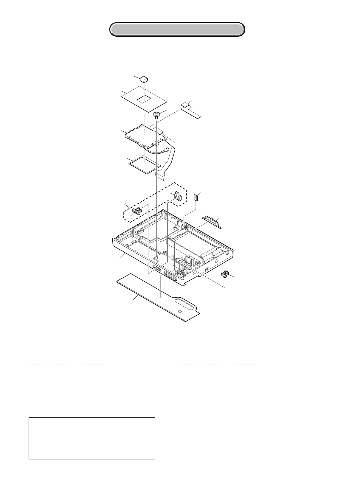
2-1-2. TOP CASE SECTION
ns : not supplied
57
55
54
2. REPAIR PARTS LIST
2. REPAIR PARTS LIST
ns
56
59
53
52
(Note)
ns
51
ns
ns
60
61
Ref. No. Part No. Description Ref. No. Part No. Description
51 X-2067-598-1 LCD WINDOW ASSY
52 A-1133-810-B TOP CASE ASSY SERVICE (Note)
53 A-1133-815-A HOLD KEY ASSY SERVICE
54 2-629-870-01 LCD DAMPER
55 A-1133-872-A LCD SET
Note :
When the TOP CASE ASSY SERVICE (Ref. No.52
on this page) is going to be replaced with the TOP
CASE ASSY SERVICE with suffix-B, do not install
the two parts that are shown as “ns” (not supplied)
on page 2-3.
56 4-671-885-01 SCREW, TAPPING, SPECIAL
57 2-637-218-01 LCD HOLDER INSULATOR
59 2-637-219-01 LCD FPC TAPE
60 2-629-873-01 POWER BUTTON
61 2-629-871-01 CANCEL BUTTON
HDPS-M10
2-4
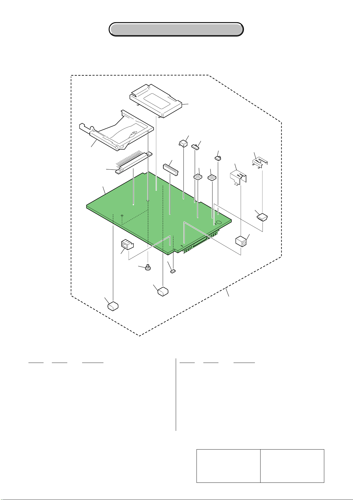
2-1-3. PWB ASSEMBLY
ns : not supplied
2. REPAIR PARTS LIST
2. REPAIR PARTS LIST
CN4
CN8
S4
103
CN3
101
ns
CN7
102
101
F1
CN1
S1
S2
S3
ns
ns
CN6
CN5
104
Ref. No. Part No. Description Ref. No. Part No. Description
101 2-108-394-01 GASKET (PWB)
102 7-627-553-47 PRECISION SCREW +P 2X4 TYPE 3
103 1-818-690-11 CONNECTOR, CARD (CF CARD)
104 A-1133-809-A PWB ASSY SERVICE
CN1 1-819-856-61 CONNECTOR, FFC/FPC (ZIF) 30P (LCD)
CN3 1-816-617-11 HEADER PIN (CF CARD)
CN4 1-817-653-11 MEMORY STICK CONNECTOR
CN5 1-817-998-11 JACK, DC
HDPS-M10
CN6 1-817-171-11 MINI-B USB CONNECTOR 5PIN
CN7 1-770-160-21 PIN, CONNECTOR (PC BOARD) 2P (BATTERY)
* CN8 1-580-055-21 PIN, CONNECTOR (SMD) 2P (BACKLIGHT)
0 F1 1-576-415-11 FUSE, MICRO (1608 TYPE) (2A/32V)
S1 1-572-595-11 SWITCH, TACTIL (REFLOW TYPE)
S2 1-572-595-11 SWITCH, TACTIL (REFLOW TYPE)
S3 1-771-627-11 SWITCH, TACTIL (POWER)
S4 1-762-078-11 SWITCH, SLIDE (HOLD)
Note :
The components identified by
mark 0 or dotted line with mark
0 are critical for safety.
Replace only with part number
specified.
2-5
(COPY/CANCEL)
(COPY/CANCEL)
Note :
Les composants identifiés par
une marque 0 sont critiques
pour la sécurité.
Ne les remplacer que par une
pièce portant le numéro spécifié.
 Loading...