

Page 1
SERVICE MANUAL
Revision History
Revision History
DISASSEMBLY
REPAIR PARTS LIST
ADJUSTMENTS
SPECIFICATIONS
DISASSEMBLY
REPAIR PARTS LIST
ADJUSTMENTS
SPECIFICATIONS
How to use
Acrobat Reader
How to use
Acrobat Reader
Ver. 1.3 2007. 01
Revised-1
HDPS-M1
HDPS-M1
US Model
Canadian Model
AEP Model
UK Model
E Model
Australian Model
Chinese Model
Hong Kong Model
Korea Model
Japanese Model
Link
Link
HDPS-M1
9-876-748-12
Sony EMCS Co.
HDD PHOTO STORAGE
2007A1600-1
©2007.01
Published by Kohda TEC
Page 2

SPECIFICATIONS
Storage capacity
40 GB
(Formatted with FAT32. 1 GB amounts to
1,000,000,000 bytes.)
Media slots
“Memory Stick” slot × 1
CompactFlash slot × 1
Supported media
“Memory Stick” (“Memory Stick Duo”)
CompactFlash cards (CF cards)
(Type I, II, Microdrive)
Interface
USB 2.0 (Hi-Speed/Full-Speed)*
Connector
USB (mini-B) × 1
Power supply
Lithium-ion rechargeable battery
(internal)
100 - 240 V AC, 50/60 Hz
Power consumption
10 W maximum
Dimensions
Approx. 135 × 30 × 92 mm
(5.3 × 1.2 × 3.6 in.)
(W × H × D)
Mass
Approx. 295 g (1 0.4 oz.)
* If the connected computer does not support
USB 2.0, transfer speed will be according to
Full-speed USB (12 Mbps).
Supplied accessories
AC power adapter (1)
Carrying case (1)
Carrying strap (1)
Operating instructions (1)
PhotoDiary software (on the hard disk)
Power cord (1)
Read me first (1)
USB cable (1)
Warranty card (1)
Design and specifications are subject to
change without notice.
Ambient conditions
Operating temperature: 5°C to 40°C (40°F
to 104°F) (temperature gradient less than
10°C/hour (50°F/hour))
Operating humidity: 20% to 80%
(non-condensing)
HDPS-M1
— 2 —
Page 3

SAFETY CHECK-OUT
After correcting the original service problem, perform the following
safety checks before releasing the set to the customer.
1. Check the area of your repair for unsoldered or poorly-soldered
connections. Check the entire board surface for solder splashes
and bridges.
2. Check the interboard wiring to ensure that no wires are
"pinched" or contact high-wattage resistors.
3. Look for unauthorized replacement parts, particularly
transistors, that were installed during a previous repair . Point
them out to the customer and recommend their replacement.
4. Look for parts which, through functioning, show obvious signs
of deterioration. Point them out to the customer and
recommend their replacement.
5. Check the B+ voltage to see it is at the values specified.
6. Flexible Circuit Board Repairing
• Keep the temperature of the soldering iron around 270˚C
during repairing.
• Do not touch the soldering iron on the same conductor of the
circuit board (within 3 times).
• Be careful not to apply force on the conductor when soldering
or unsoldering.
SAFETY-RELATED COMPONENT WARNING!!
COMPONENTS IDENTIFIED BY MARK 0 OR DOTTED LINE WITH
MARK 0 ON THE SCHEMATIC DIAGRAMS AND IN THE PARTS
LIST ARE CRITICAL TO SAFE OPERATION. REPLACE THESE
COMPONENTS WITH SONY PARTS WHOSE PART NUMBERS
APPEAR AS SHOWN IN THIS MANUAL OR IN SUPPLEMENTS
PUBLISHED BY SONY.
Unleaded solder
Boards requiring use of unleaded solder are printed with the leadfree mark (LF) indicating the solder contains no lead.
(Caution: Some printed circuit boards may not come printed with
the lead free mark due to their particular size.)
: LEAD FREE MARK
Unleaded solder has the following characteristics.
• Unleaded solder melts at a temperature about 40°C higher than
ordinary solder.
Ordinary soldering irons can be used but the iron tip has to be
applied to the solder joint for a slightly longer time.
Soldering irons using a temperature regulator should be set to
about 350°C.
Caution: The printed pattern (copper foil) may peel away if the
heated tip is applied for too long, so be careful!
• Strong viscosity
Unleaded solder is more viscous (sticky, less prone to flow) than
ordinary solder so use caution not to let solder bridges occur such
as on IC pins, etc.
• Usable with ordinary solder
It is best to use only unleaded solder but unleaded solder may
also be added to ordinary solder.
ATTENTION AU COMPOSANT AYANT RAPPORT
À LA SÉCURITÉ!
LES COMPOSANTS IDENTIFÉS PAR UNE MARQUE 0 SUR LES
DIAGRAMMES SCHÉMATIQUES ET LA LISTE DES PIÈCES SONT
CRITIQUES POUR LA SÉCURITÉ DE FONCTIONNEMENT. NE
REMPLACER CES COMPOSANTS QUE PAR DES PIÈSES SONY
DONT LES NUMÉROS SONT DONNÉS DANS CE MANUEL OU
DANS LES SUPPÉMENTS PUBLIÉS PAR SONY.
CAUTION :
Danger of explosion if battery is incorrectly replaced.
Replace only with the same or equivalent type.
HDPS-M1
— 3 —
Page 4

TABLE OF CONTENTS
1. DISASSEMBLY ·························································1-1
2. REPAIR PARTS LIST
2-1. EXPLODED VIEWS ······················································2-3
2-1-1.OVERALL SECTION·····················································2-3
2-1-2.PWB ASSEMBL Y···························································2-4
3. ADJUSTMENTS
3-1. PREPARATIONS BEFORE ADJUSTMENT·················3-1
3-1-1.List of Service Tools ························································3-1
3-1-2.Preparations ·····································································3-2
3-1-3.Order of Adjustments ······················································3-3
3-2. ADJUSTMENTS·····························································3-4
3-2-1.Inquiry & Firmware Check ·············································3-4
3-2-2.NTFS format····································································3-5
3-2-3.HDD Self Format ···························································· 3-5
3-2-4.Stand Alone Copy Check and Final Function (USB Mode)
Check···············································································3-6
3-2-4-1. Stand Alone Copy Check·········································3-6
3-2-4-2. Final Function (USB Mode) Check ·························3-6
3-2-4-2-1. Preparations ·····························································3-6
3-2-4-2-2. Final Function (USB Mode) Check ·························3-7
3-2-5. LED Color Confirmation ··············································3-8
3-2-6. USB 1.1 Confirmation Check ·······································3-8
3-2-7. Final Function 2 (USB Mode) Check ··························· 3-9
3-2-8. Burn In (Read) Check ················································· 3-10
3-2-9. Burn In (Write) Check ················································3-11
3-2-10. NTFS format ·······························································3-12
3-2-11. HDD Self Format························································3-12
3-2-12. Photo Diary Software Download ································3-12
HDPS-M1
— 4 —
Page 5
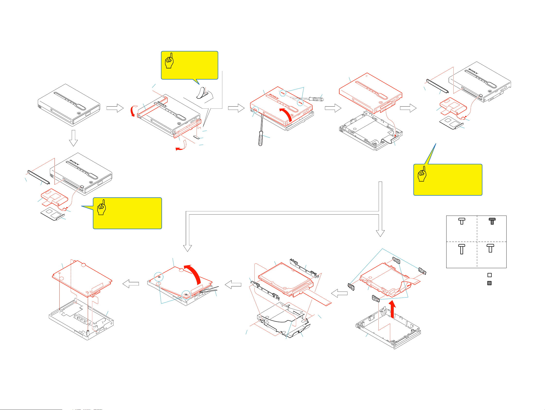
The following flow chart shows the disassembly procedure.
A
1
2
4
B
3
b
1
Open the lid (R) assembly in the
direction of the arrow a.
2
Screw (M2x3.5) black
3
Open the lid (L) assembly in the
direction of the arrow b.
Caution
Note: The foot rubber
cannot be reused.
C
1
a
B
4
Screw (M2x3.5) black
5
Foot rubber
6
Tapping screw (M2x8) silver
C
5
2
1. DISASSEMBLY
2
5
4
6
3
1
Slide through opening area by
using rubber tip tweezer for rear side.
2
Two claws
3
Slide through opening area by
using rubber tip tweezer.
4
Claw
5
Open the top case sub assembly
in the direction of the arrow.
2
1
1
1
Flexible flat cable (50P)
2
Top case sub assembly
A
1
2
4
3
5
1
Screw (M2x3.5) silver
2
Battery cover assembly
3
Connector (2P)
4
Battery assembly
5
Battery plate, Battery plate sheet
Caution
Note: Be sure to fully charge the
Battery after the repair is completed.
4
1
Screw (M2x3.5) silver
2
Battery cover assembly
3
Connector (2P)
3
5
4
Battery assembly
5
Battery plate, Battery plate sheet
2
1
Top case sub assembly
2
PWB board
Caution
Note: Be sure to fully charge the
Battery after the repair is completed.
1
1
2
3
in the direction of the arrow.
3
2
Lift PWB out from bottom case.
Two positioning holes
Remove the PWB board
1
4
D
1
1
Two screws (M3x4) silver
2
Two screws (M3x4) silver
3
Peel off the sheet.
4
Absorber bracket B,
Two spacers A, B
AB
Screw
M2x3.5
7-627-853-37
3
7
3
5
D
2
6
5
Absorber bracket A,
Two spacers A, B
6
Bottom shield A, etc
7
Hard disk drive, IOM-F board,
Flexible flat cable
1
1
2
4
Remove the hard disk drive, Bottom shield A,
etc in the direction of the arrow.
2
Two shock absorbers B
3
Two shock absorbers A
4
Bottom case assembly, Lid (R) assembly,
Lid (L) assembly,
C
Screw
M2x8
7-685-105-14
Screw
M2x3.5
2-108-513-01
D
Screw
M3x4
4-683-253-01
Silver
Black
HDPS-M1
1-1 1-2E
Page 6
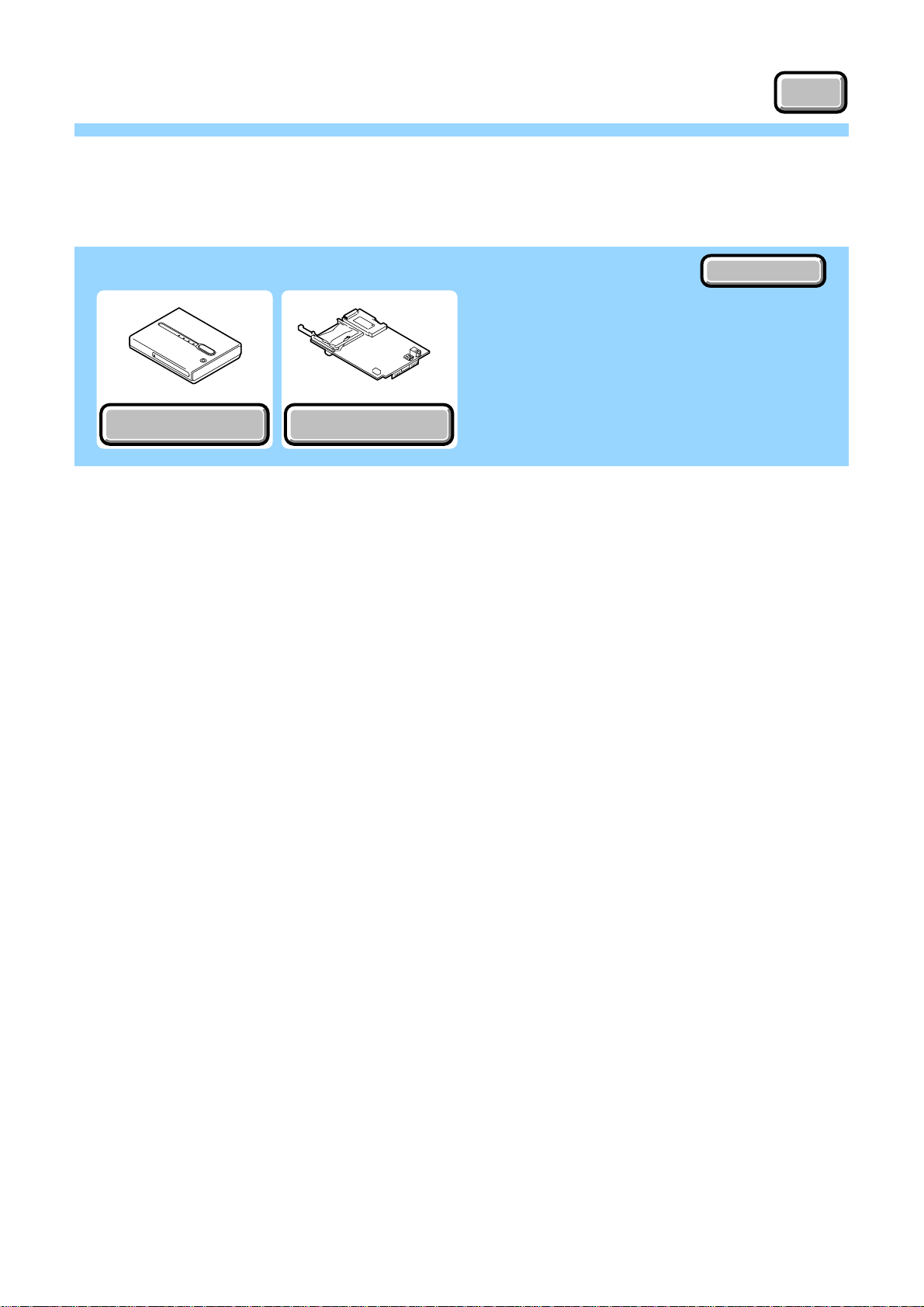
2. REPAIR PARTS LIST
OVERALL SECTION
OVERALL SECTION
NOTE
NOTE
Link
Link
EXPLODED VIEWS
EXPLODED VIEWS
PWB ASSEMBLY
PWB ASSEMBLY
ACCESSORIES
ACCESSORIES
HDPS-M1
Page 7

2. REPAIR PARTS LIST
2. REPAIR PARTS LIST
NOTE:
• -XX, -X mean standardized parts, so they may have some differences from
the original one.
• Items marked “*” are not stocked since they are seldom required for routine
service. Some delay should be anticipated when ordering these items.
• The mechanical parts with no reference number in the exploded views are not
supplied.
• Due to standardization, replacements in the parts list may be different from
the parts specified in the diagrams or the components used on the set.
• CAPACITORS:
uF: µF
• COILS
uH: µH
• RESISTORS
All resistors are in ohms.
METAL: metal-film resistor
METAL OXIDE: Metal Oxide-film resistor
F: nonflammable
• SEMICONDUCTORS
In each case, u: µ, for example:
uA...: µA... , uPA... , µPA... ,
uPB... , µPB... , uPC... , µPC... ,
uPD..., µPD...
When indicating parts by reference number,
please include the board name.
The components identified by mark 0 or
dotted line with mark 0 are critical for safety.
Replace only with part number specified.
Les composants identifiés par une marque
0 sont critiques pour la sécurité.
Ne les remplacer que par une pièce portant
le numéro spécifié.
HDPS-M1
2-1
Page 8
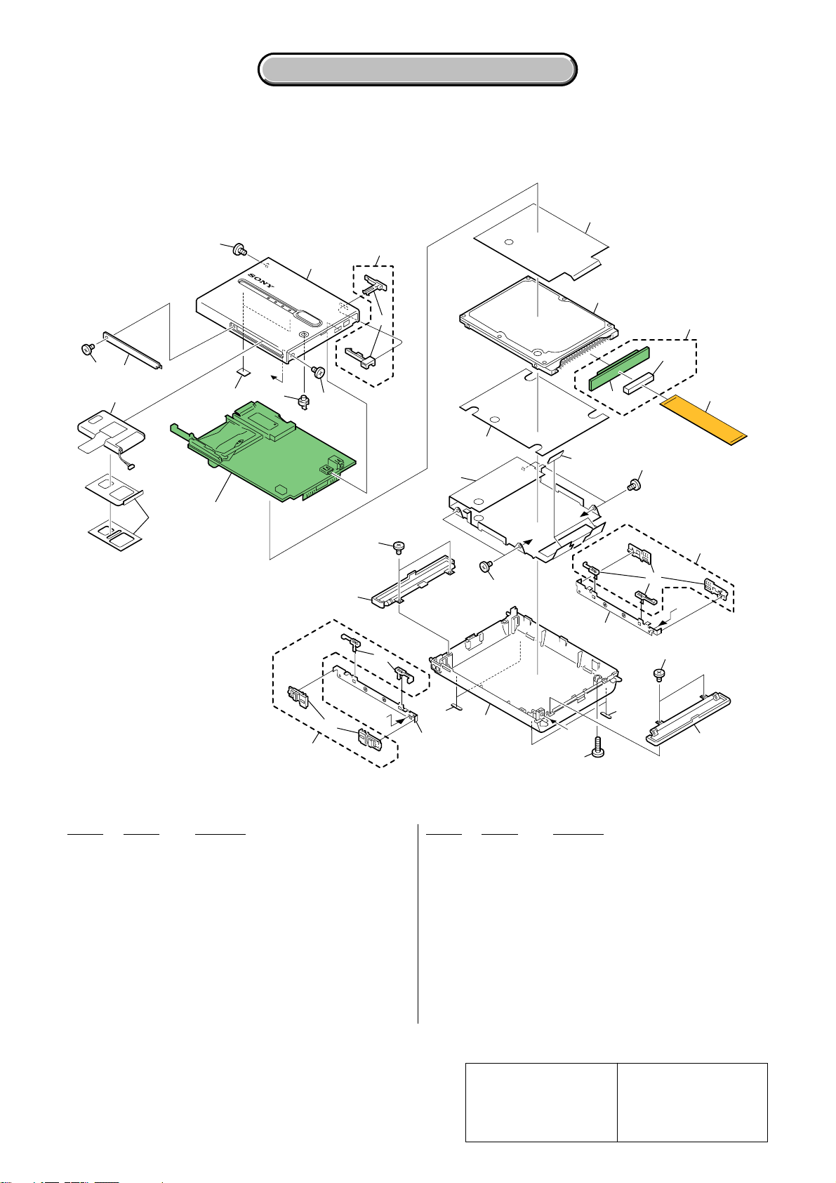
2-1. EXPLODED VIEWS
2-1-1. OVERALL SECTION
ns : not supplied
2. REPAIR PARTS LIST
2. REPAIR PARTS LIST
ns
6
10
7
13
ns
4
5
3
PWB board
ns
(See page 2-4)
ns
C
8
6
ns
9
ns
ns
17
A
B
12
19
17
14
CN101
15
20
ns
A
18
ns
19
ns
B
20
Ref. No. Part No. Description Ref. No. Part No. Description
1 4-682-526-01 RUBBER FOOT
2 7-685-105-14 TAPPING +P 2X8 NON-SLIT
3 A-1068-384-A BATTERY ASSY
4 7-627-853-37 PRECISION SCREW +P 2X3.5 TYPE3
5 A-1067-345-A BATTERY COVER ASSY
6 2-108-513-01 SCREW M2X3.5 (BLACK)
7 X-2022-492-1 TOP CASE SUB ASSY
8 4-682-518-01 CANCEL BUTTON
9 2-059-938-01 BOTTOM SHIELD A
10 A-1068-381-A POWER SWITCH ASSY SERVICE
11 A-1067-343-A LID (R) ASSY
HDPS-M1
1
16
21
12 A-1067-342-A LID (L) ASSY
0 13 1-797-021-11 HDD (40GB, IC25N04ATMR04)
14 A-1067-749-A IOM-F1 MOUNTED
15 1-829-549-11 CABLE, FLEXIBLE FLAT
16 A-1067-341-A BOTTOM CASE ASSY
17 4-683-253-01 SCREW
18 4-682-534-01 ABSORBER BRACKET A
19 7-685-102-14 SCREW +P 2X4 TYPE2 NON-SLIT
20 A-1068-382-A ABSORBER ASSY SERVICE
21 4-682-535-01 ABSORBER BRACKET B
CN101 1-778-652-11 CONNECTOR, FFC (ZIF) 50P
Note :
The components identified by
mark 0 or dotted line with mark
0 are critical for safety.
Replace only with part number
specified.
2-3
C
1
11
2
Note :
Les composants identifiés par
une marque 0 sont critiques
pour la sécurité.
Ne les remplacer que par une
pièce portant le numéro spécifié.
Page 9

2-1-2. PWB ASSEMBLY
ns : not supplied
2. REPAIR PARTS LIST
2. REPAIR PARTS LIST
CN4
51
CN3
ns
CN7
S4
ns
S3
CN5
CN2
F1
S2
53
52
Ref. No. Part No. Description Ref. No. Part No. Description
51 1-818-690-11 CONNECTOR, CARD (CF CARD)
52 7-627-553-47 SCREW,PRECISION +P 2X4
53 A-1068-383-A PWB ASSY SERVICE
CN2 1-817-171-11 MINI-B USB CONNECTOR 5PIN
CN3 1-817-617-11 CONNECTOR, SO-DIMM
CN4 1-817-653-11 MEMORY STICK CONNECTOR
HDPS-M1
CN5 1-817-998-11 JACK, DC
CN7 1-770-160-21 PIN, CONNECTOR (PC BOARD) 2P
0 F1 1-576-416-21 FUSE 2A 36V
S2 1-692-950-21 SWITCH, SLIDE
S3 1-771-105-11 SWITCH, TACTILE
S4 1-771-105-11 SWITCH, TACTILE
Note :
The components identified by
mark 0 or dotted line with mark
0 are critical for safety.
Replace only with part number
specified.
2-4
Note :
Les composants identifiés par
une marque 0 sont critiques
pour la sécurité.
Ne les remplacer que par une
pièce portant le numéro spécifié.
Page 10

2. REPAIR PARTS LIST
2. REPAIR PARTS LIST
Checking supplied accessories.
Make sure that the following accessories are supplied with your unit of HDPS-M1.
Power cord (Main lead) (1)
(AUS model)
0
1-555-074-32
Power cord (Main lead) (1)
(AEP model)
0
1-575-131-61
Power cord (Main lead) (1)
AC Power Adaptor (HDAC-M1) (1)
(US/CND/AEP/UK/HK/J/
E: Except Singapore model)
0
AC Power Adaptor (HDAC-M1) (1)
(AUS/CH/KR/E: Singapore model)
0
(US/CND model)
0
1-757-562-21
Power cord (Main lead) (1)
(KR model)
0
1-776-985-32
Power cord (Main lead) (1)
(CH model)
0
1-782-476-22
Power cord (Main lead) (1)
(J/E: Except Singapore model)
0
1-790-732-32
USB cable (USB 5P) (1)
1-827-038-11
Power cord (Main lead) (1)
(UK/HK/E: Singapore model)
0
1-823-935-51
Other accessories
2-109-914-01 FLYER (LID OPEN/CLOSE) (JAPANESE) (J)
2-109-914-11 FLYER (LID OPEN/CLOSE) (ENGLISH) (EXCEPT J)
2-109-917-01 READ ME FIRST (JAPANESE) (J)
2-109-917-11 READ ME FIRST (ENGLISH) (EXCEPT J)
1-478-852-11
1-478-852-21
Carrying case (1)
2-022-454-01
Carrying strap (1)
3-253-246-01
• Abbreviation
CND : Canadian model
AUS : Australian model
CH : Chinese model
HK : Hong Kong model
KR : Korea model
J : Japanese model
HDPS-M1
2-5E
Note :
The components identified by
mark 0 or dotted line with mark
0 are critical for safety.
Replace only with part number
specified.
Note :
Les composants identifiés par
une marque 0 sont critiques
pour la sécurité.
Ne les remplacer que par une
pièce portant le numéro spécifié.
Page 11

3. ADJUSTMENTS
3-1. PREPARATIONS BEFORE ADJUSTMENT
3-1-1. List of Service Tools
J-1 J-2 J-3
Personal computer
with
Widows ME/XP
installed and with
USB 2.0 port
USB cable
1-827-038-11
AC power adaptor
(HDAC-M1)
(Note1)
J-4
J-5
AC power code
(Note1)
J-7 J-8
CompactFlash T ype I Microdrive
Note1:
Model AC power adaptor AC power code
J 1-478-852-11 1-790-732-32
US, CND 1-478-852-11 1-757-562-21
UK 1-478-852-11 1-823-935-51
AEP 1-478-852-11 1-575-131-61
E (Except 1-478-852-11 1-790-732-32
Singapore)
HK 1-478-852-11 1-823-935-51
CH 1-478-852-21 1-782-476-22
KR 1-478-852-21 1-776-985-32
AUS 1-478-852-21 1-555-074-32
E (Singapore) 1-478-852-21 1-823-935-51
Fig. 3-1-1.
Note2: Contact your service headquarter of each area how to get the
J-6
Software for
HDPS-M1
Memory Stick PRO
(Note2)
HDPS1-Photo/Manual (1)
and
HDPS1-Photo/Manual (2)
(CD-ROM)(2 discs)
(Note2)
“Software for HDPS-M1”, “HDPS1-Photo/Manual (1)” and
“HDPS1-Photo/Manual (2)”.
• Abbreviation
CND : Canadian model
AUS : Australian model
CH : Chinese model
HK : Hong Kong model
KR : Korea model
J : Japanese model
HDPS-M1
3-1
Page 12

3-1-2. Preparations
1) Connect the equipment for adjustments according to Fig. 3-1-2.
System requirements of the PC:
OS: Windows Me/XP (Windows XP is recommended)
USB: USB2.0
USB1.1 (only for “USB 1.1 Confirmation Check”)
Preparations:
Note: Contact your service headquarter of each area how to get the
“Software for HDPS-M1”, “HDPS1-Photo/Manual (1)” and
“HDPS1-Photo/Manual (2)”.
1) Copy the “StoragerFunctionCheck” folder of the “Software for
HDPS-M1” to the desk top or arbitrary folder of the PC.
2) Start the “TRF.bat” program of the “FC1” folder and make the
test files (Refer to “How to make the test files”.)
3) Copy the following file to a MemoryStick PRO.
trf_file.001 (For “Stand Alone Copy Check and Final Function
(USB Mode) Check”)
4) Copy the following file to a CompactFlash.
trf_file.002 (For “Stand Alone Copy Check and Final Function
(USB Mode) Check”)
5) Copy the following file to a Microdrive.
trf_file.003 (For “Stand Alone Copy Check and Final Function
(USB Mode) Check”)
Contents of “Software for HDPS-M1”:
Folder File or folder Usage
Bi(w) 80minAg.exe Burn In (Write) Check
FC1 Compare.bat Stand Alone Copy Check and Final
TRF.exe Function (USB Mode) Check
TRF.bat
FC2_BI(r)
strdevtst7.exe Final Function 2 (USB Mode)
Check Burn In (Read) Check
Fw Inq ChkFirm.exe Inquiry & Firmware Check
How to make the test files:
1) Double click the “Trf.bat” of the “FC1” folder.
2) Check that “TRF.bat” window is displayed.
3) Wait until “TRF.bat” window is closed.
4) Open the “temp” folder of the C drive, and check that the three
following files are made.
trf_file.001, trf_file.002, trf_file.003
Matrix for changed parts and operation required for Storager Service
No
1
Inquiry & Firmware Check
2
NTFS Format
3
HDD Self Format
Operation Name
Parts Changed Software for HDPS-M1
HDD
Yes
Yes
Yes
Battery
Yes
No
Yes
PWB
Yes
No
Yes
Check Items
For NG Drives
Yes
No
No
Folder
Fw Inq
N/A
N/A
File or folder
Chk Firm.exe
(Windows Format)
(Unique Self Format)
compare.bat (Note1)
Stand Alone Copy Check and Final
4
Function (USB Mode) Check
Yes
Yes
Yes
Yes
FC1
(Copy the test file from each
media (MsPRO/CF/MicroDrv)
to HDD of HDPS-M1)
5
LED Color Confirmation
6
USB 1.1 Confirmation Check
7
Final Function 2 (USB Mode) Check
8
Burn In (Read) Check
9
Burn In (Write) Check
10
NTFS Format
11
HDD Self Format
12
Photo Diary Software Download
Note1: Use “trf_file.001”, “trf_file.002” and “trf_file.003” as test file.
Note2: “HDPS” folder and “ReadMe.html” file are stored in the HDPS1-Photo/Manual CD-ROMs.
Note3: Adjustment and check works should be carried out according to the operation number as shown in the above table (top to bottom).
Yes
Yes
Yes
Yes
Yes
No
Yes
No
No
Yes
Yes
Yes
Yes
Yes
Yes
Yes
No
No
No
No
No
No
Yes
No
Yes
Yes
Yes
Yes
Yes
No
No
No
N/A
N/A
FC2_BI(r)
FC2_BI(r)
Bi(w)
N/A
N/A
N/A
(Press by hand)
(Windows screen)
strdevtst7.exe
strdevtst7.exe
80minAg.exe
(Windows Format)
(Unique Self Format)
HDPS folder and ReadMe.html
(Note2)
HDPS-M1
3-2
Page 13

3-1-3. Order of Adjustments
1) Inquiry & Firmware Check
2) NTFS Format
3) HDD Self Format
4) Stand Alone Copy Check and Final Function (USB Mode) Check
5) LED Color Confirmation
6) USB 1.1 Confirmation Check
7) Final Function 2 (USB Mode) Check
8) Burn In (Read) Check
9) Burn In (Write) Check
10) NTFS Format
11) HDD Self Format
12) Photo Diary Software Download
[CONNECTION OF EQUIPMENT]
Personal computer
(with USB 2.0 port)
USB
DC IN
Fig. 3-1-2.
AC power
adaptor
USB
AC IN
HDPS-M1
3-3
Page 14

3-2. ADJUSTMENTS
3-2-1. Inquiry & Firmware Check
Mode USB
Power Supply AC power adaptor
Test Program ChkFirm.exe
MemoryStick Not necessary
CompactFlash Not necessary
Microdrive Not necessary
Specified Value “OK” is displayed in the status window
Checking method:
1) Disconnect the USB cable.
2) Double click “ChkFirm.exe” of the “Fw Inq” folder, and start
“Firmware Checker” on the PC.
3) Check that “Firmware Checker” screen is displayed.
4) Type the firmware version (for example, it is “1.00”) in the
firm version window of “Firmware Checker” screen.
5) Connect the USB cable.
6) Turn on the power of HDPS-M1.
7) Wait until the product information appears.
8) Check that “OK” is displayed in the status window.
If NG, re-type the correct firmware version as stated in
“Firmware Version” column. Then click “Refresh” of the file
menu.
Fig. 3-1-3.
9) Click “Exit” of the f ile menu to close the “Firmware Checker”
screen.
Fig. 3-1-4.
HDPS-M1
3-4
Page 15

3-2-2. NTFS format
/
Mode USB
Power Supply AC power adaptor
Test Program Not necessary
MemoryStick Not necessary
CompactFlash Not necessary
Microdrive Not necessary
Specified V alue Nothing
Formatting method:
1) Disconnect the USB cable.
2) Double click “My computer” icon on the PC and open “My
computer” screen.
3) Check the hard disk drives displayed on the “My computer”
screen. These are the hard disk drives built in PC.
4) Connect HDPS-M1 and PC using the USB cable.
5) Turn on the power of HDPS-M1.
6) Wait a moment.
7) Check that the “Local Disk (G:)” of HDPS-M1 is newly
displayed on the “Hard Disk Drives” window of the “My
computer” screen.
Note: The drive letter (e.g., “G:”) differs depending on the PC.
3-2-3. HDD Self Format
Note: The hard disk drive of the unit must be NTFS formatted before
perform “HDD Self Format”.
Mode Stand alone
Power Supply AC power adaptor
Test Program Not necessary
MemoryStick Not necessary
CompactFlash Not necessary
Microdrive Not necessary
Specified Value Nothing
Formatting method:
1) Disconnect the USB cable.
2) Turn on the power of the HDPS-M1.
3) Check that the following LEDs are lit.
POWER (green), HDD (green), COPY (amber)
4) While pressing COPY button, press CANCEL button 5 times
within 5 seconds.
When all LEDs become green and begin to blink, release COPY
button.
5) Press COPY button once, color of COPY LED becomes red.
6) Press COPY button once ag ain to start up “HDD self format”.
While “HDD self format” is performed, color of COPY LED
turns from red to amber and then green alternately.
7) After “HDD self format” is completed, only POWER LED is
lit green and other LEDs are not lit.
Fig. 3-1-5.
8) Right click “Local Disk (G:)”.
9) Select “Format” and Click it.
Fig. 3-1-6.
10) Check “Quick Format”.
11) Click “START” to start NTFS format.
POWER LED
MS LED
CF LED
HDD LED
COPY button
COPY LED
DC IN jack
USB connector
CANCEL button
Fig. 3-1-8.
Note:
1) If “HDD self format” cannot be performed, please ensure that
POWER LED, HDD LED and COPY LED are lit, after turn
on the power.
If only POWER LED is lit, the HDD is formatted already.
2) Make sure that COPY button is pushed and it is not released
when pressing the CANCEL button 5 times.
3) When “HDD self format” cannot be performed although it tries
twice, the HDD drive is malfunction.
HDPS-M1
Fig. 3-1-7.
3-5
Page 16

3-2-4. Stand Alone Copy Check and Final Function
(USB Mode) Check
3-2-4-1. Stand Alone Copy Check
Mode Stand alone
Power Supply AC power adaptor
Test Program Not necessary
Memory Stick Memory Stick PRO which memorize
“trf_file.001” file.
CompactFlash CompactFlash which memorize
“trf_file.002” file.
Microdrive Microdrive which memorize
“trf_file.003” file.
Specified Value LEDs should be lit correctly. (Note)
Note: When MS LED and CF LED light up conversely , correct data is not
written in the EEPROM.
Checking method:
1) Disconnect the USB cable.
2) Turn on the power of HDPS-M1.
3) Insert the Memory Stick to the Memory Stick slot.
4) Wait until MS LED, HDD LED and COPY LED are lit green.
5) Press COPY button to copy files from the Memory Stick to
HDD.
6) Confirm that MS LED, HDD LED and COPY LED blink
alternately during data transfer.
7) When the copy is completed, only COPY LED is lit green, and
MS LED and HDD LED are not lit.
8) Eject the Memory Stick.
9) Insert the CompactFlash to the CompactFlash/micro drive slot.
10) Wait until CF LED, HDD LED and COPY LED are lit green.
11) Press COPY button to copy files from the CompactFlash to
HDD.
12) Confirm that CF LED, HDD LED and COPY LED blink
alternately during data transfer.
13) When the copy is completed, only COPY LED is lit green, and
CF LED and HDD LED are not lit.
14) Eject the CompactFlash.
15) Insert the micro drive to the CompactFlash/micro drive slot.
16) Wait until CF LED, HDD LED and COPY LED are lit green.
17) Press COPY button to copy files from the micro dri ve to HDD.
18) Confirm that CF LED, HDD LED and COPY LED blink
alternately during data transfer.
19) When the copy is completed, only COPY LED is lit green, and
CF LED and HDD LED are not lit.
20) Eject the micro drive.
21) Must execute item “4-2. Final Function (USB Mode) Check”.
3-2-4-2. Final Function (USB Mode) Check 3-2-4-2-1. Preparations
Mode USB
Power Supply AC power adaptor
Test Program Compare.bat
MemoryStick Not necessary
CompactFlash Not necessary
Microdrive Not necessary
Specified Value Nothing
Preparations:
1) Double click “My computer” icon on the PC and open “My
computer” screen.
2) Check the drives displayed on the “My computer” screen. These
are the drives built in the PC.
3) Connect HDPS-M1 and PC using the USB cable.
4) Turn on the power of HDPS-M1.
5) Wait a moment.
6) Check that the following three drives are newly displayed on
the “My computer” screen (See Fig. 3-1-9.). And check that
each drive letter is the same as the following ta ble. If not, change
the drive letter, or modify the “compare.bat” program.
Drive name
Local Disk (G:) G Hard Disk
Removable Disk (E:) E Memory Stick
Removable Disk (F:) F Compact Flash/Micro Drive
Drive letter
Storage media
HDPS-M1
Fig. 3-1-9.
3-6
Page 17

How to change the drive letter:
1) Select “Setup” of the start menu of Windows on the PC.
2) Select “Control panel” and open it.
3) Open “Administrative Tools”.
4) Open “Computer Management”.
5) Double click “Disk management”.
6) Left-click the drive which you want to change the drive letter,
then select “Change drive letter or paths”
7) Click “Change”.
8) Choose a drive letter, which you want to change, and click
“OK”.
How to fit the “Compare.bat” pr ogram to your computer
1) Right-click the “Compare.bat” file of the “FC1” folder, then
select “Edit”.
2) The notepad application starts, and the edit screen of the
“Compare.bat” file is displayed.
3) Change the drive letters as follows.
g: t Drive letter of HDPS-M1’s hard disk drive which
displayed on your computer system.
e: t Drive letter of HDPS-M1’s MemoryStick drive which
displayed on your computer system.
f: t Drive letter of HDPS-M1’s CompactFlash/Microdrive
drive which displayed on your computer system.
4) Save the “Compare.bat” file.
Compare.bat
3-2-4-2-2. Final Function (USB Mode) Check
Note: “Final Function (USB Mode) Check” should be carried out upon
completion of “Stand Alone Copy Check”.
Mode USB
Power Supply AC power adaptor
Test Program Compare.bat
MemoryStick Memory Stick PRO which memorize
“trf_file.001” file.
CompactFlash CompactFlash which memorize
“trf_file.002” file.
Microdrive Microdrive which memorize
“trf_file.003” file.
Specified Value “Files compare OK” should be
displayed.
Checking method:
1) Connect HDPS-M1 and PC using the USB cable.
2) Turn on the power of HDPS-M1.
3) Double click the “Compare.bat” of the “FC1” folder to start up
“Compare batch program” on the PC.
4) Check that “Compare batch program” window is displayed,
and it prompts for insertion of the Memory Stick PRO.
Echo Off
Echo Insert Sony MS Pro
pause
comp g:\STORE.IPS\20040127.001\trf_file.001 e:\trf_file.001
echo Remove MS Pro
echo Insert CF
pause
comp g:\STORE.IPS\20040127.002\trf_file.002 f:\trf_file.002
echo Remove CF
echo Insert Micro Drive
pause
comp g:\STORE.IPS\20040127.003\trf_file.003 f:\trf_file.003
Echo Finish
pause
Fig. 3-1-10.
Fig. 3-1-11.
5) Insert the Memory Stick PRO to the Memory Stick slot.
6) When “E drive” or “F drive” window open up, close it.
Note: The drive letter (e.g., “F”) differs depending on the PC.
7) Click “Compare ba tch program” window and press an y key to
start comparison of the file of HDD, and the file of Memory
Stick.
8) Comparison of files is finished, and when its result is normal,
“Files compare OK” will be displayed on the window.
9) When “Compare more files (Y/N)?” is displayed on the window ,
Type “N” and press “Enter” key.
Fig. 3-1-12.
10) When “Remov e Ms Pro” and “Insert CF” are displayed on the
window, remove the Memory Stick PRO and insert the
CompactFlash.
11) Henceforth, check the CompactFlash and the Microdrive
accordance with the instruction on the window by the same
method as the Memory Stick PRO (repeat item 6 to 9).
HDPS-M1
3-7
Page 18

3-2-5. LED Color Confirmation
/
Mode Stand alone
Power Supply AC power adaptor
Test Program Not necessary
MemoryStick Not necessary
CompactFlash Not necessary
Microdrive Not necessary
Specified Value LED colors should be the same
intensity (green)
3-2-6. USB 1.1 Confirmation Check
Mode USB
Power Supply AC power adaptor
Test Program Not necessary
MemoryStick Not necessary
CompactFlash Not necessary
Microdrive Not necessary
Specified Value Three drives should be newly
displayed
Checking method:
1) Disconnect the USB cable.
2) Turn on the power of HDPS-M1.
3) Check that the only POWER LED is lit.
4) Press the CANCEL button and hold it, wait until the follo wing
four LEDs are lit. And check that the LED colors are the same
intensity (green). If the color is different, the unit is malfunction.
POWER, MS, CF, HDD
5) After “LED Color Confirmation”, release the CANCEL button.
POWER LED
MS LED
CF LED
HDD LED
COPY button
COPY LED
DC IN jack
USB connector
CANCEL button
Fig. 3-1-13.
System requirements of the PC:
PC with the USB1.1 connector
Checking method:
1) Disconnect the USB cable.
2) Double click “My computer” icon on the PC and open “My
computer” screen.
3) Check the drives displayed on the “My computer” screen. These
are the drives built in the PC.
4) Connect HDPS-M1 and USB1.1 connector of the PC using the
USB cable.
5) Turn on the power of HDPS-M1.
6) Wait until only POWER LED is lit.
7) Check that “HI-SPEED USB Device Plugged into non-HISPEED USB Hub” message is displayed.
Note: This message is displayed when the operation system of the PC
is Windows XP.
Fig. 3-1-14.
8) Check that the following three drives are newly displayed on
the “My computer” screen.
Note: The drive letters (e.g., “G:”) differ depending on the PC.
Drive name
Drive letter
Storage media
Local Disk (G:) G Hard Disk
Removable Disk (E:) E Memory Stick
Removable Disk (F:) F Micro Drive/Compact Flash
HDPS-M1
Fig. 3-1-15.
3-8
Page 19

3-2-7. Final Function 2 (USB Mode) Check
Mode USB
Power Supply AC power adaptor
Test Program strdevtst7.exe
MemoryStick Blank Memory Stick PRO
CompactFlash Blank CompactFlash
Microdrive Blank Microdrive
Specified Value Memory Stick PRO:
Error rate = 0.000000E + 000
CompactFlash:
Error rate = 0.000000E + 000
Microdrive:
Error rate = 0.000000E + 000
Hard disk drive:
Error rate = 5.000000E – 002 or less
Note1: When the storage media is checked, the data memorized on it will
be erased.
Note2: When the hard disk is checked, the data memorized on it will be
erased. After the hard disk check finishes, perform “3. HDD Self
Format” again.
Checking method:
1) Connect HDPS-M1 and PC using the USB cable.
2) Turn on the power of HDPS-M1.
3) Double click “strdevtst7.exe” of the “FC2_BI(r)” folder, and
start “Storage device test” on the PC.
4) Check that “Storage device test” screen is displayed.
8) Check that “Input Drive Data” screen is displayed.
Fig. 3-1-17.
9) Input serial No. and media remarks.
For example:
Hard disk ..................................................................... HDD
Memory Stick PRO........................................................ MS
CompactFlash ................................................................. CF
Microdrive..................................................................... MD
10) Click “OK” button.
11) “Storage device test” is performed automatically.
12) When the “Count” of the ERROR RATE window reaches the
following value, click “T est Abort” button to abort the test.
Storage media Memory Compact
Microdrive
Hard disk
Stick PRO Flash
Count 200 200 200 1000
13) Check that error rate satisfies the specified value.
Note: 0.000000E + 000 = 0.000000 × 10 0 = 0.000000 × 1 = 0 = 0%
5.000000E – 002 = 5.000000 × 10
–2
= 5.000000 × 0.01 = 0.05 = 5%
Fig. 3-1-16.
5) Set up “Storage device test”, as shown in the following table,
corresponding to the storage media.
Storage media Memory Compact
Microdrive
Stick PRO Flash
Drive name E F F G
(Note)
Read No check No check No check No check
Write Check Check Check Check
Random Check Check Check Check
Verify Check Check Check Check
Time out setting
653msec 333msec 583msec 128msec
Automatic No check No check No check No check
If error occurred, ...
Note: The drive names (e.g., “E:”) differ depending on the PC.
No check No check No check No check
6) Insert a storage media to be checked in the slot.
7) Click “Test Start” button.
HDPS-M1
Fig. 3-1-18.
Hard disk
3-9
Page 20

3-2-8. Burn In (Read) Check
Mode USB
Power Supply AC power adaptor
Test Program strdevtst7.exe
MemoryStick Not necessary
CompactFlash Not necessary
Microdrive Not necessary
Specified Value Hard disk drive: Errors count = 0
Checking method:
1) Connect HDPS-M1 and PC using the USB cable.
2) Turn on the power of HDPS-M1.
3) Double click “strdevtst7.exe” of the “FC2_BI(r)” folder, and
start “Storage device test” on the PC.
4) Check that “Storage device test” screen is displayed.
Fig. 3-1-19.
7) Check that “Input Drive Data” screen is displayed.
Fig. 3-1-20.
8) Input serial No and media remarks.
For example:
Hard disk ............................................................ HDD(BIR)
9) Click “OK” button.
10) “Storage device test” is performed automatically.
11) Before the “Count” of the ERROR RATE window reaches
“76308”, when the “Read error was occurred. Do you want to
continue?” message is displayed, the hard disk drive is
malfunction. Click the “Yes” button to abort the test.
Fig. 3-1-21.
12) When the “Count” of the ERROR RATE window reaches
“76308”, the test is completed automatically.
13) Check that the “Errors” window indicate “1”.
Note: The “Errors” window (Errors count) will indicate “1” after the
“Count” reaches “76308”, but this is not true error, so it is
considered that the hard disk drive has no error.
When the “Errors” window (Errors count) indicate “2” or more,
the hard disk drive is malfunction.
5) Set up “Storage device test” as follows.
Drive name (Note) G
Read Check
Write No check
Random No check
Verify No check
Time out setting 4000msec
Automatic No check
If error occurred, Check
display warning
Note: The drive letter (e.g., “G:”) of the hard disk driv e differs depending
on the PC.
6) Click “Test Start” button.
Fig. 3-1-22.
HDPS-M1
3-10
Page 21

3-2-9. Burn In (Write) Check
Mode USB
Power Supply AC power adaptor
Test Program 80minAg.exe
MemoryStick Not necessary
CompactFlash Not necessary
Microdrive Not necessary
Specified Value Hard disk drive:
Error rate = 5.000000E – 002 or less
Note: When the hard disk is checked, the data memorized on hard disk
will be erased. After the hard disk check finishes, perform “3. HDD
Self Format” again.
Checking method:
1) Connect HDPS-M1 and PC using the USB cable.
2) Turn on the power of HDPS-M1.
3) Double click “80minAg.exe” of the “Bi(w)” folder, and start
“Storage device test” on the PC.
4) Check that “Storage device test” screen is displayed.
7) Check that “Input Drive Data” screen is displayed.
Fig. 3-1-24.
8) Input serial No and media remarks.
For example:
Hard disk ........................................................... HDD(BIW)
9) Click “OK” button.
10) “Storage device test” is performed automatically.
Note: When testing is in progress, do not move the mouse or hit the
unit because this will cause write error.
11) When it passes for 80 minutes after the test start, the test is
completed automatically.
12) Check that error rate satisfies the specified value.
Note: 5.000000E – 002 = 5.000000 × 10 –2 = 5.000000 × 0.01 = 0.05
= 5%
Fig. 3-1-23.
5) Set up “Storage device test” as follows.
Drive name (Note) G
Read No check
Write Check
Random Check
Verify Check
Time out setting 128msec
Automatic No check
If error occurred, No check
display warning
Note: The drive letter (e.g., “G:”) differs depending on the PC.
6) Click “Test Start” button.
Fig. 3-1-25.
13) Check that POWER LED is lit green and not blinking.
If POWER LED is blinking, wait until it stops blinking before
removing the AC power adapter.
HDPS-M1
3-11
Page 22

3-2-10. NTFS format
This operation is the same as “3-2-2. NTFS format”. Please refer to
“3-2-2. NTFS format”.
3-2-11. HDD Self Format
This operation is the same as “3-2-3. HDD Self Format”. Please
refer to “3-2-3. HDD Self Format”.
3-2-12. Photo Diary Software Download
Mode USB
Power Supply AC power adaptor
Test Program “HDPS” folder and “ReadMe.html”
file in the HDPS1-Photo/Manual
CD-ROMs
MemoryStick Not necessary
CompactFlash Not necessary
Microdrive Not necessary
Specified Value About 740MB
Download method:
1) Connect HDPS-M1 and PC using the USB cable.
2) Turn on the power of HDPS-M1.
3) Copy “HDPS” folder and “ReadMe.html” file into the root
folder of the hard disk drive of HDPS-M1 from the HDPS1Photo/Manual CD-ROMs.
4) Open the root folder of the hard disk drive of HDPS-M1, and
check that there are “STORE.IPS” folder, “HDPS” folder and
“ReadMe.html” file.
5) Check that the capacity of “HDPS” folder of HDPS-M1 is about
740MB.
HDPS-M1
3-12E
Page 23

SERVICE MANUAL
Ver. 1.3 2007. 01
This SUPPLEMENT-2 is the revised version
of SUPPLEMENT-1.
Replace the SUPPLEMENT-1 (9-876-748-81)
with the SUPPLEMENT-2.
Please discard the SUPPLEMENT-1.
SUPPLEMENT-2
HDPS-M1
HDPS-M1
US Model
Canadian Model
AEP Model
UK Model
E Model
Australian Model
Chinese Model
Hong Kong Model
Korea Model
Japanese Model
2. REPAIR PARTS LIST
2-1. EXPLODED VIEWS
Page
2-1-1. OVERALL SECTION
0 13 1-797-021-11 HDD (40GB, IC25N04ATMR04)
2-3
18 4-682-534-01 ABSORBER BRACKET A
21 4-682-535-01 ABSORBER BRACKET B
Before change After change
File this supplement-2 with the service manual.
(DI06-148)
• Change of repair parts list
: Changed portion
Ref. No. Part No. DescriptionRef. No. Part No. Description
0 13 1-797-315-11 HDD (40GB, HTS424040M9AT00)
18 A-1134-386-A ABSORBER ASSY SERVICE, A
21 A-1134-387-A ABSORBER ASSY SERVICE, B
HDPS-M1
9-876-748-82
Sony EMCS Co.
2007A1600-1
©2007.01
Published by Kohda TEC
Page 24

Checking supplied accessories.
Page
Before change After change
Other accessories
2-109-914-01 FLYER (LID OPEN/CLOSE) (J)
2-109-914-11 FLYER (LID OPEN/CLOSE) (EXCEPT J)
: Changed portion : Added portion : Deleted portion
2-pin conversion adaptor (1)
(E model)
0
1-569-008-11
2-5E
2-109-917-11 READ ME FIRST (ENGLISH) (EXCEPT J)
2-109-917-11 READ ME FIRST (ENGLISH, TRADITIONAL CHINESE,
2-109-917-21 READ ME FIRST (ENGLISH) (CND)
2-109-917-31 READ ME FIRST
2-109-917-41 READ ME FIRST (ENGLISH) (US)
2-109-917-51 READ ME FIRST
Note :
The components identified by
mark 0 or dotted line with mark
0 are critical for safety.
Replace only with part number
specified.
SIMPLIFIED CHINESE, KOREAN)
(HK, CH, AUS, E, KR)
(ENGLISH, FRENCH, GERMAN, ITALIAN,
SPANISH, PORTUGUESE, RUSSIAN)
(AEP, UK)
(ENGLISH, SPANISH, PORTUGUESE) (E)
•Abbreviation
CND : Canadian model
AUS: Australian model
CH : Chinese model
HK : Hong Kong model
KR : Korea model
J: Japanese model
Note :
Les composants identifiés par
une marque 0 sont critiques
pour la sécurité.
Ne les remplacer que par une
pièce portant le numéro spécifié.
HDPS-M1
— 2 —
Page 25

[Description of main button functions on toolbar of the Adobe Acrobat Reader Ver5.0 (for Windows)]
Toolbar
Printing a text
1. Click the Print button .
2. Specify a printer, print range, number of copies, and other options, and then click [OK].
Application of printing:
To set a range to be printed within a page, select the graphic
selection tool
be printed, and then click the Print button.
and drag on the page to enclose a range to
Finding a text
1. Click the Find button .
2. Enter a character string to be found into a text box, and click
the [Find]. (Specify the find options as necessary)
Application to the Service Manual:
T o execute “find” from current page to ward the previous pages,
select the check box “Find Backward” and then click the
“Find”.
3. Open the find dialog box again, and click the [Find Again] and
you can find the matched character strings displayed next.
(Character strings entered previously are displayed as they are
in the text box.)
Reversing the screens displayed once
• To reverse the previous screens (operation) one by one, click
the .
• To advance the reversed screens (operation) one by one, click
the .
Application to the Service Manual:
This function allows you to go and back between circuit diagram and printed circuit board diagram, and accordingly it
will be convenient for the voltage check.
Moving with link
1. Select either palm tool , zoom tool , text selection tool
, or graphic selection tool .
2. Place the pointer in the position in a text where the link exists
(such as a button on cover and the table of contents page, or
blue characters on the removal flowchart page or drawing
page), and the pointer will change to the forefinger form
3. Then, click the link. (You will go to the link destination.)
Moving with bookmark:
Click an item (text) on the bookmark pallet, and you can move
to the link destination. Also, clicking
hidden items.
(To go back to original state, click )
can display the
.
Application to the Service Manual:
The parts on the drawing pages (block diagrams, circuit diagrams, printed circuit boards) and parts list pages in a text
can be found using this find function. For example, find a
Ref. No. of IC on the block diagram, and click the [Find Again]
continuously, so that you can move to the Ref. No. of IC on
the circuit diagram or printed circuit board diagram successively.
Note: The find function may not be applied to the Service
Manual depending on the date of issue.
Switching a page
• To move to the first page, click the .
• To move to the last page, click the .
• To move to the previous page, click the
• To move to the next page, click the
.
.
Zooming or rotating the screen display
“Zoom in/out”
• Click the triangle button in the zoom control box to select the
display magnification. Or, you may click
ing in or out.
“Rotate”
• Click rotate tool , and the page then rotates 90 degrees each.
or for zoom-
Application to the Service Manual:
The printed circuit board diagram you see now can be changed
to the same direction as the set.
Page 26

Reverse
987674814.pdf
Revision History
Ver.
1.0
1.1
1.2
1.3
Date
2004.06
2004.12
2006.11
2007.01
History
Official Release
Revised-1
Supplement-1
(DI06-126)
Supplement-2
(DI06-148)
Contents
—
Change of Adjustments
Change of repair parts list
Change of repair parts list
This SUPPLEMENT-2 is the revised version
of SUPPLEMENT-1.
Replace the SUPPLEMENT-1 (9-876-748-
81) with the SUPPLEMENT-2.
Please discard the SUPPLEMENT-1.
S.M. Rev.
issued
—
Ye s
No
No
HDPS-M1
 Loading...