

Sony HCDGNZ-7-D, HCDGNZ-9-D, HCDGNZ-8-D Service manual
HCD-GNZ7D/GNZ8D/GNZ9D
SERVICE MANUAL
Ver. 1.1 2005. 12
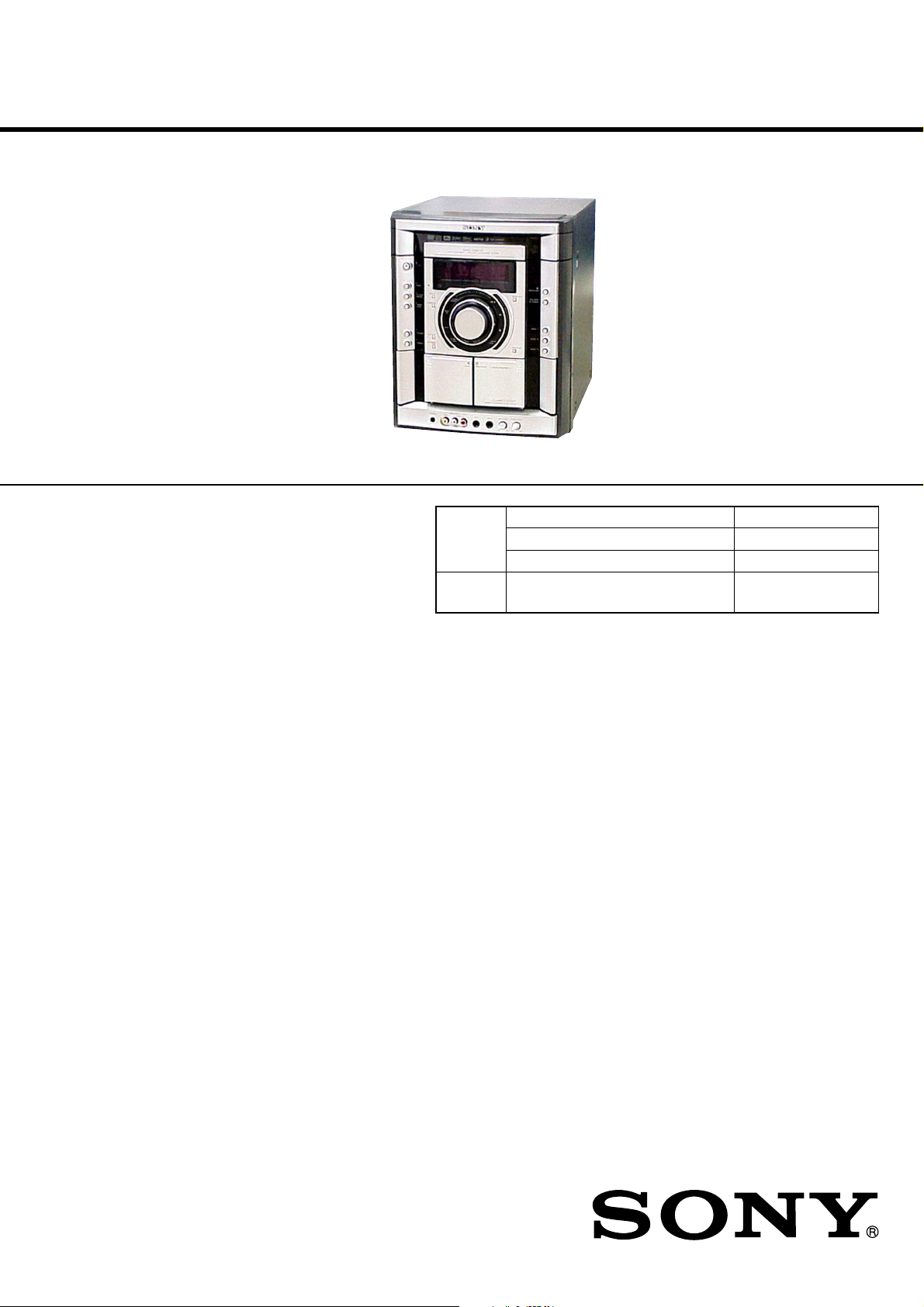
• HCD-GNZ7D/GNZ8D/GNZ9D are
the tuner, deck, DVD and amplifier
section in MHC-GNZ7D/GNZ8D/
GNZ9D.
(Photo: HCD-GNZ7D)
DVD
Section
Tape Deck
Section
E Model
HCD-GNZ7D/GNZ8D/GNZ9D
Australian Model
HCD-GNZ9D
Model Name Using Similar Mechanism NEW
DVD Mechanism Type CDM74HF-DVBU101//C
Optical Pick-up Name KHM-310CAB/C2NP
Model Name Using Similar Machanism NEW
Amplifier section
HCD-GNZ9D
The following measured at AC 120, 127, 220, 230 – 240 V,
50/60 Hz
Continuous RMS power output (reference)
Front speaker: 115 + 115 watts
(6 ohms at 1 kHz, 10%
THD)
Center speaker: 50 watts (6 ohms at 1 kHz,
10% THD)
Surround speaker: 50 + 50 watts
(6 ohms at 1 kHz, 10%
THD)
Subwoofer: 170 watts (4 ohms at
100 Hz, 10% THD)
HCD-GNZ8D
The following measured at AC 120, 127, 220, 230 – 240 V,
50/60 Hz
Continuous RMS power output (reference)
Front speaker: 100 + 100 watts
(6 ohms at 1 kHz, 10%
THD)
Center speaker: 40 watts (6 ohms at 1 kHz,
10% THD)
Surround speaker: 40 + 40 watts
(6 ohms at 1 kHz, 10%
THD)
HCD-GNZ7D
The following measured at AC 120, 127, 220, 230 – 240 V,
50/60 Hz
Continuous RMS power output (reference)
100 + 100 watts
(6 ohms at 1 kHz, 10%
THD)
SPECIFICATIONS
Inputs
VIDEO/SAT IN (audio) (phono jacks):
voltage 450/250 mV,
impedance 47 kilohms
VIDEO INPUT VIDEO (phono jack):
1 Vp-p, 75 ohms
VIDEO INPUT AUDIO (phono jacks):
voltage 250 mV,
impedance 47 kilohms
MIC1/MIC2 (phone jack):
sensitivity 1 mV,
impedance 10 kilohms
Outputs
VIDEO/SAT OUT (audio) (phono jacks):
voltage 250 mV,
impedance 1 kilohm
VIDEO OUT (phono jack):
max. output level
1 Vp-p, unbalanced, Sync
negative, load impedance
75 ohms
S-VIDEO OUT (4-pin/mini-DIN jack):
Y: 1 Vp-p, unbalanced,
Sync negative,
C: 0.286 Vp-p, load
impedance 75 ohms
COMPONENT VIDEO OUT:
Y: 1 Vp-p, 75 ohms
PB, PR: 0.7 Vp-p, 75 ohms
– Continued on next page –
DVD DECK RECEIVER
9-879-622-02
2005L04-1
© 2005. 12
Sony Corporation
Home Audio Division
Published by Sony Engineering Corporation
1

HCD-GNZ7D/GNZ8D/GNZ9D
DIGITAL OPTICAL OUT (Square optical connector jack,
rear panel) (HCD-GNZ7D only)
Wav elength 660 nm
PHONES (stereo mini jack):
accepts headphones of
8 ohms or more
Disc player section
System Compact disc and digital
audio and video system
Laser Semiconductor laser
(DVD: λ=650 nm,
CD: λ=790 nm)
Emission duration:
continuous
Frequency response DVD (PCM 48 kHz):
2 Hz – 22 kHz (±1 dB)
CD: 2 Hz – 20 kHz (±1 dB)
Video color system format
Latin American model:
NTSC
Other models: NTSC, PAL
Tape deck section
Recording system 4-track 2-channel stereo
Frequency response 40 – 13,000 Hz (±3 dB),
using Sony TYPE I
cassette
Tuner section
FM stereo, FM/AM superheterodyne tuner
FM tuner section
Tuning range 87.5 – 108.0 MHz
(50-kHz step)
Antenna FM lead antenna
Antenna terminals 75 ohm unbalanced
Intermediate frequency 10.7 MHz
AM tuner section
Tuning range
Latin American models: 530 – 1,710 kHz (with the
interval set at 10 kHz)
531 – 1,710 kHz (with the
interval set at 9 kHz)
Saudi Arabian model: 531 – 1,602 kHz (with the
interval set at 9 kHz)
Other models: 531 – 1,602 kHz (with the
interval set at 9 kHz)
530 – 1,710 kHz (with the
interval set at 10 kHz)
Antenna AM loop antenna
Antenna terminals External antenna terminal
Intermediate frequency 450 kHz
General
Power requirements
Australian model: 230 – 240 V AC, 50/60 Hz
Saudi Arabian model: 120 – 127 V, 220 V or
230 – 240 V AC,
50/60 Hz
Adjustable with voltage
selector
Indian model: 220 – 240 V AC, 50/60 Hz
Mexican model: 127 V AC, 60 Hz
Thai model: 220 V AC, 50/60 Hz
Other models: 120 V, 220 V or 230 –
240 V AC, 50/60 Hz
Adjustable with voltage
selector
Power consumption
MHC-GNZ9D 400 watts
MHC-GNZ8D 280 watts
MHC-GNZ7D 210 watts
Dimensions (w/h/d)
MHC-GNZ9D Approx. 280 × 326 × 400 mm
MHC-GNZ8D/GNZ7D Approx. 280 × 326 × 380 mm
Mass (excl. speakers)
HCD-GNZ9D Approx. 14 kg
HCD-GNZ8D Approx. 12 kg
HCD-GNZ7D Approx. 11 kg
Design and specifications are subject to change without
notice.
SAFETY-RELATED COMPONENT WARNING!!
COMPONENTS IDENTIFIED BY MARK 0 OR DOTTED LINE
WITH MARK 0 ON THE SCHEMATIC DIAGRAMS AND IN
THE PARTS LIST ARE CRITICAL TO SAFE OPERATION.
REPLACE THESE COMPONENTS WITH SONY PARTS WHOSE
PA RT NUMBERS APPEAR AS SHOWN IN THIS MANUAL OR
IN SUPPLEMENTS PUBLISHED BY SONY.
2
HCD-GNZ7D/GNZ8D/GNZ9D
Ver. 1.1
Notes on Chip Component Replacement
•Never reuse a disconnected chip component.
• Notice that the minus side of a tantalum capacitor may be
damaged by heat.
Flexible Circuit Board Repairing
•Keep the temperature of soldering iron around 270°C during
repairing.
• Do not touch the soldering iron on the same conductor of the
circuit board (within 3 times).
• Be careful not to apply force on the conductor when soldering
or unsoldering.
UNLEADED SOLDER
Boards requiring use of unleaded solder are printed with the lead
free mark (LF) indicating the solder contains no lead.
(Caution: Some printed circuit boards may not come printed with
the lead free mark due to their particular size)
: LEAD FREE MARK
Unleaded solder has the following characteristics.
• Unleaded solder melts at a temperature about 40 °C higher than
ordinary solder.
Ordinary soldering irons can be used but the iron tip has to be
applied to the solder joint for a slightly longer time.
Soldering irons using a temperature regulator should be set to about
350 °C.
Caution: The printed pattern (copper foil) may peel away if the
heated tip is applied for too long, so be careful!
• Strong viscosity
Unleaded solder is more viscou-s (sticky , less prone to flo w) than
ordinary solder so use caution not to let solder bridges occur such
as on IC pins, etc.
• Usable with ordinary solder
It is best to use only unleaded solder but unleaded solder may also
be added to ordinary solder.
NOTES ON LASER DIODE EMISSION CHECK
The laser beam on this model is concentrated so as to be focused on
the disc reflective surface by the objective lens in the optical pickup block. Therefore, when checking the laser diode emission,
observe from more than 30 cm away from the objective lens.
Laser component in this product is capable
of emitting radiation exceeding the limit for
Class 1.
This appliance is
claassified as a CLASS 1
LASER product. This
label is located on the
rear exterior.
Note on DMB10 board or DMB11 board replacement
New part of EEP ROM (IC103) on the DMB10 board or DMB11
board cannot be used. Therefore, if the mounted DMB10 board (A1095-784-A, etc.) is replaced, exchange new EEP ROM (IC103)
with that used before the replacement.
CAUTION
Use of controls or adjustments or performance of procedures
other than those specified herein may result in hazardous
radiation exposure.
NOTES ON HANDLING THE OPTICAL PICK-UP BLOCK
OR BASE UNIT
The laser diode in the optical pick-up block may suffer electrostatic
breakdown because of the potential difference generated by the
charged electrostatic load, etc. on clothing and the human body.
During repair, pay attention to electrostatic break-down and also
use the procedure in the printed matter which is included in the
repair parts.
The flexible board is easily damaged and should be handled with
care.
3
HCD-GNZ7D/GNZ8D/GNZ9D
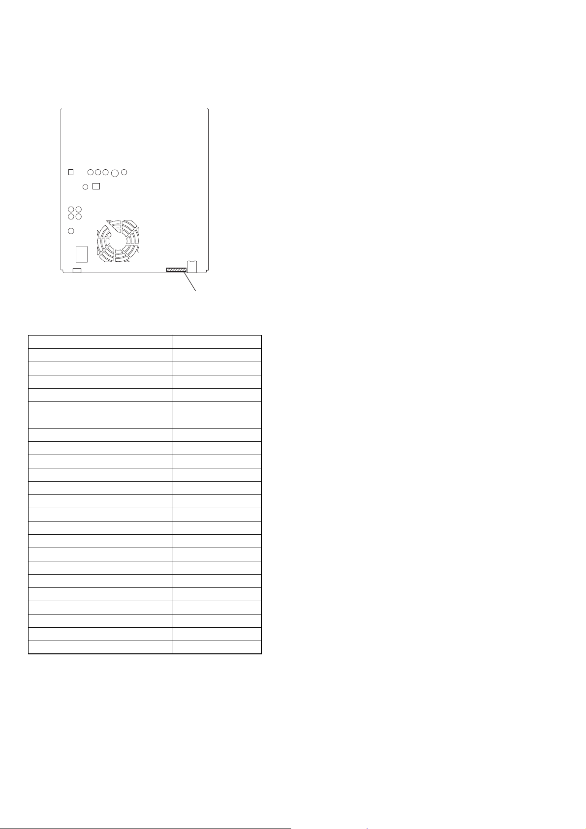
MODEL IDENTIFICATION
– BACK PANEL –
PA RTS No.
MODEL PARTS No.
GNZ9D: SP 2-582-750-0s
GNZ9D: E3, E15 2-582-750-1s
GNZ9D: E12, E13 2-582-750-2s
GNZ9D: PH 2-582-750-3s
GNZ9D: EA 2-582-750-4s
GNZ9D: TH 2-582-750-5s
GNZ9D: AUS 2-582-750-6s
GNZ9D: E2 2-582-750-7s
GNZ9D: E51 2-582-750-8s
GNZ9D: MX 2-582-750-9s
GNZ8D: SP 2-582-751-0s
GNZ8D: E3, E15 2-582-751-1s
GNZ8D: E12, E13 2-582-751-2s
GNZ8D: PH 2-582-751-3s
GNZ8D: EA 2-582-751-4s
GNZ8D: TH 2-582-751-5s
GNZ7D: SP 2-582-752-0s
GNZ7D: E3, E15 2-582-752-1s
GNZ7D: E12, E13 2-582-752-2s
GNZ7D: PH 2-582-752-3s
GNZ7D: EA 2-582-752-4s
GNZ7D: TH 2-582-752-5s
GNZ7D: E2 2-582-752-6s
•Abbreviation
E2 : 120 V AC area in E model
E3 : 240 V AC area in E model
E12 : 220-240 V AC area in E model
E13 : 220-230 V AC area in E model
E15 : Iran model
E51 : Chilean and Peruvian model
AUS: Australian model
EA : Saudi arabia model
PH : Philippine model
SP : Singapore model
MX : Mexican model
TH : Thai model
4

TABLE OF CONTENTS
HCD-GNZ7D/GNZ8D/GNZ9D
1. SERVICE NOTE
1-1. Service Position of CDM ...................................................... 6
1-2. Service Position of DMB10 Board, Video Board ................. 6
1-3. Service Position of TCM ....................................................... 7
1-4. Service Position of Front AMP Board .................................. 7
1-5. Service Position of Subwoofer Board ................................... 8
2. GENERAL
Main Unit ................................................................................ 9
Remote Control ..................................................................... 10
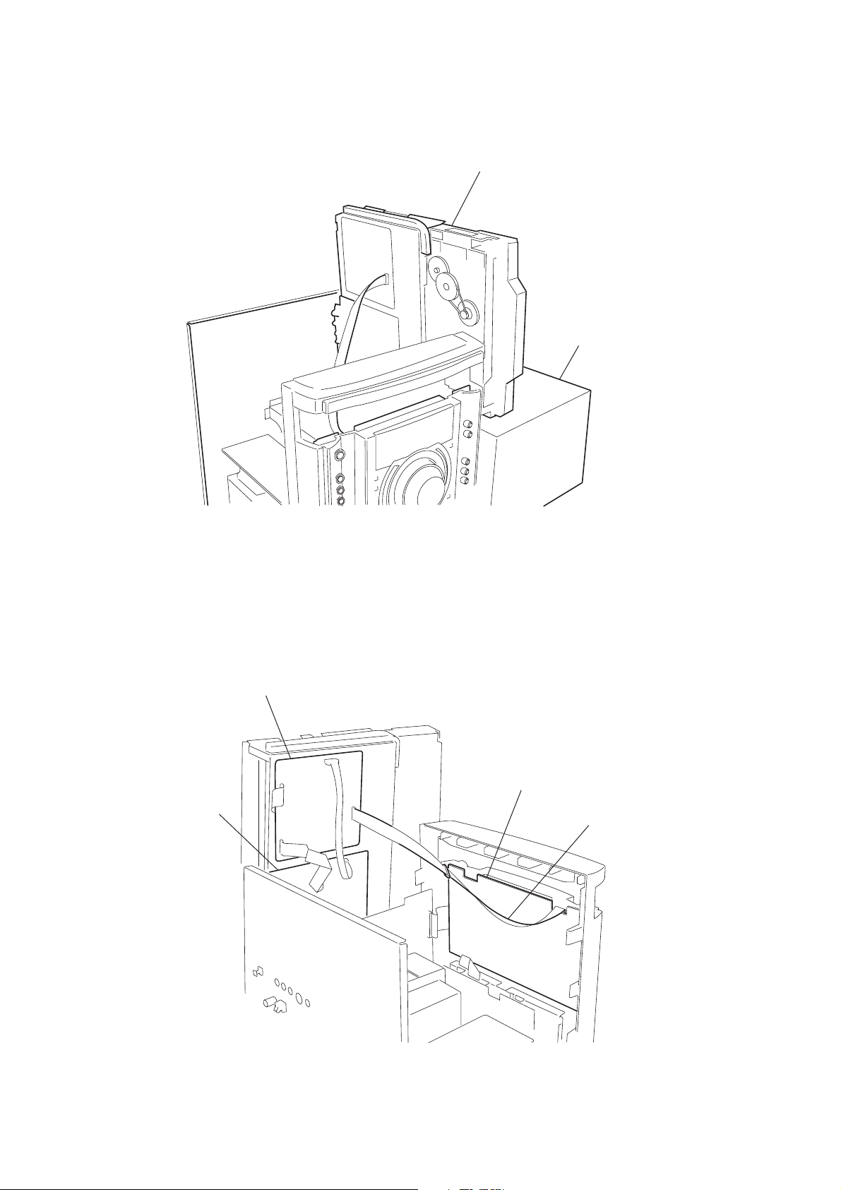
3. DISASSEMBLY
3-1. Case ..................................................................................... 12
3-2. Loading Panel Assy............................................................. 12
3-3. Front Panel Section ............................................................. 13
3-4. DVD Block Section ............................................................. 13
3-5. Tape Mechanism Section .................................................... 14
3-6. Panel Board ......................................................................... 14
3-7. Jack Board ........................................................................... 15
3-8. Back Panel Section .............................................................. 15
3-9. Boards Section .................................................................... 16
3-10. Audio Board (HCD-GNZ8D/GNZ9D) ............................. 16
3-11. Audio Board (HCD-GNZ7D)............................................ 17
3-12. Surround AMP Board (HCD-GNZ8D/GNZ9D),
Subwoofer Board (HCD-GNZ9D) .................................... 17
3-13. DVD Mechanism Block, Video Board, DMB10 Board .... 18
3-14. Pick-up Unit ...................................................................... 18
3-15. SW Board, Driver Board ................................................... 19
3-16. Sensor Board ..................................................................... 19
3-17. Motor (TB) Board ............................................................. 20
3-18. Motor (LD) Board ............................................................. 20
4. TEST MODE
4-1. General Description ............................................................ 22
4-2. Starting Test Mode .............................................................. 22
4-3. Drive Manual Operation...................................................... 22
4-4. Mirror Time Adjustment ..................................................... 22
4-5. Executing IOP Measurement .............................................. 24
7. DIAGRAMS
7-1. Block Diagram — RF/Servo Section — ............................. 35
7-2. Block Diagram — Video Section — ................................... 36
7-3. Block Diagram — Audio Section — .................................. 37
7-4. Block Diagram — Main Section — .................................... 38
7-5. Block Diagram — Function/Power Section — ................... 39
7-6. Printed Wiring Boards — Driver Section —....................... 41
7-7. Schematic Diagram — Driver Section — ........................... 42
7-8. Printed Wiring Board — DMB10 Section (Side A) — ....... 43
7-9. Printed Wiring Board — DMB10 Section (Side B) — ....... 44
7-10. Schematic Diagram — DMB10 Section (1/4) — ............. 45
7-11. Schematic Diagram — DMB10 Section (2/4) — ............. 46
7-12. Schematic Diagram — DMB10 Section (3/4) — ............. 47
7-13. Schematic Diagram — DMB10 Section (4/4) — ............. 48
7-14. Printed Wiring Board — Audio Section —....................... 49
7-15. Schematic Diagram — Audio Section (1/3) —................. 50
7-16. Schematic Diagram — Audio Section (2/3) —................. 51
7-17. Schematic Diagram — Audio Section (3/3) —................. 52
7-18. Printed Wiring Board — Video Section — ....................... 53
7-19. Schematic Diagram — Video Section — .......................... 54
7-20. Printed Wiring Board — Front AMP Section — .............. 55
7-21. Schematic Diagram — Front AMP Section — ................. 56
7-22. Printed Wiring Boards — Panel Section — ...................... 57
7-23. Schematic Diagram — Panel Section (1/2) — ................. 58
7-24. Schematic Diagram — Panel Section (2/2) — ................. 59
7-25. Printed Wiring Board — Jack Section — ......................... 60
7-26. Schematic Diagram — Jack Section — ............................ 61
7-27. Printed Wiring Board — Surround AMP Section —
(HCD-GNZ8D/GNZ9D) ................................................... 62
7-28. Schematic Diagram — Surround AMP Section —
(HCD-GNZ8D/GNZ9D) ................................................... 63
7-29. Printed Wiring Board — Subwoofer Section —
(HCD-GNZ9D) ................................................................. 64
7-30. Schematic Diagram — Subwoofer Section —
(HCD-GNZ9D) ................................................................. 65
7-31. Printed Wiring Board — Trans Section — ....................... 66
7-32. Printed Wiring Board — Sub Trans Section — ................ 67
7-33. Schematic Diagram — Power Section — ......................... 68
5. MECHANICAL ADJUSTMENTS ............................... 25
6. ELECTRICAL ADJUSTMENTS................................. 26
8. EXPLODED VIEWS
8-1. Main Section ....................................................................... 71
8-2. Front Panel Section (1)........................................................ 72
8-3. Front Panel Section (2)........................................................ 73
8-4. Front Panel Section (3)........................................................ 74
8-5. DVD Block Section ............................................................. 75
8-6. Chassis Section ................................................................... 76
8-7. Audio Board Section ........................................................... 77
8-8. DVD Mechanism Deck Section (1) .................................... 78
8-9. DVD Mechanism Deck Section (2) .................................... 79
9. ELECTRICAL PARTS LIST ......................................... 80
5
HCD-GNZ7D/GNZ8D/GNZ9D
A
1-1. SERVICE POSITION OF CDM
SECTION 1
SERVICE NOTE
DVD mechanism block
stand
1-2. SERVICE POSITION OF DMB10 BOARD, VIDEO BOARD
DMB10 board
VIDEO board
PANEL board
J-2501-102-
6
1-3. SERVICE POSITION OF TCM
n
HCD-GNZ7D/GNZ8D/GNZ9D
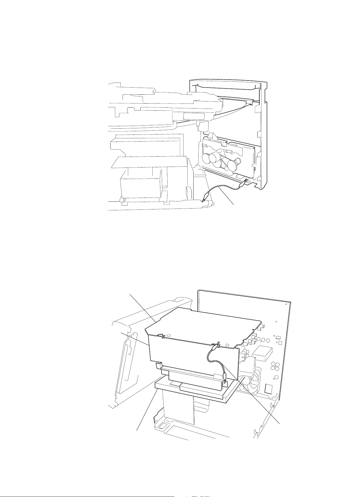
1-4. SERVICE POSITION OF FRONT AMP BOARD
AUDIO board
FRONT AMP board
earth is taken
insulating plate
earth is take
7
HCD-GNZ7D/GNZ8D/GNZ9D
d
1-5. SERVICE POSITION OF SUBWOOFER BOARD
AUDIO board
FRONT AMP boar
insulating plate
SUBWOOFER board
8
SECTION 2
w
GENERAL
List of button locations and reference pages
HCD-GNZ7D/GNZ8D/GNZ9D
This section is extracted
from instruction manual.
How to use this page
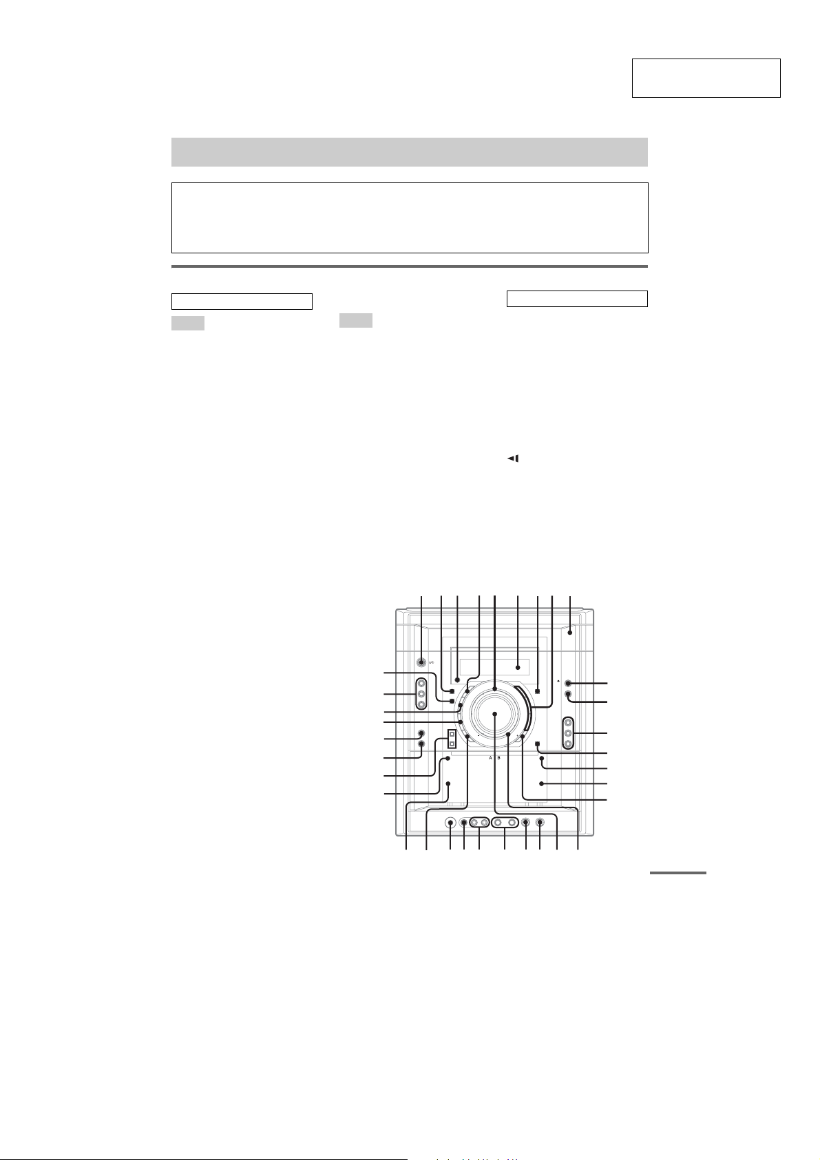
Use this page to find the location of buttons and other
parts of the system that are mentioned in the text.
Main unit
ALPHABETICAL ORDER
A – Q
CD SYNC wk (for
MHC-GNZ9D/GNZ8D/
GNZ7D)
e; (for MHC-GNZ5D) (53)
Deck A wh (52, 54)
Deck B qg (52, 53, 54, 62)
DIRECTION qd (52, 53, 54)
DISC 1 – 3 qs (18, 21, 53, 77)
DISC SKIP/EX-CHANGE qa
(12, 17, 18, 21, 53)
Disc tray 9 (17)
DISPLAY 2 (40, 63, 65, 77)
Display window 6
DVD ed (12, 40, 53)
ECHO LEVEL
EQ BAND/MEMORY 4 (57)
GROOVE ea (55)
ILLUMINATION ef
MIC 1/2 jack wa
MIC LEVEL w; (57)
Operation Dial (lL) 5
(57)
PHONES jack wf
Power illuminator qj (63)
PRESET EQ es (55, 57)
2)
ql (57)
1)
(57)
2)
(63)
R – Z
REC PAUSE/START wk (for
MHC-GNZ9D/GNZ8D/
GNZ7D)
wl (for MHC-GNZ5D) (53,
54)
Remote sensor 3
SOUND FIELD 7 (55)
TAPE A/B ed (52, 53, 54)
TUNER/BAND ed (50, 51, 54)
TUNING + qh (50, 51)
TUNING – wg (50, 51)
TV/SAT e;
VIDEO wl
VIDEO INPUT AUDIO L/R
VIDEO INPUT VIDEO jack wd
VOLUME control qk (44, 58)
2)
(54, 70)
2)
(54, 70)
jacks ws (54, 69)
(69)
ef
ed
es
ea
e;
wl
wk
wj
Illustration number
r
TAPE A/B ed (
Name of button/part Reference page
1 2
3
RR
BUTTON DESCRIPTIONS
?/1 (power) 1 (10, 51, 61, 68,
77)
nN (play) 8 (17, 39, 52, 53)
X (pause) 8 (11, 18, 52)
x (stop) 8 (12, 18, 45, 52, 53,
77)
Z OPEN/CLOSE q; (17)
Z PUSH (deck B) (eject) qf (52)
M (fast forward) qh (18, 52)
y (slow forward) qh (18)
m (rewind) wg (18, 52)
(slow rewind) wg (18)
Z PUSH (deck A) (eject) wj (52)
1)
MHC-GNZ5D has only one
MIC jack.
2)
Except for MHC-GNZ5D
4
5
nN
X
x
M y
M y
52, 53, 54
9876
)
q;
qa
qs
qd
qf
qg
qh
qj
wh
wawd wfwg
s
qkqlw;
continued
9
HCD-GNZ7D/GNZ8D/GNZ9D
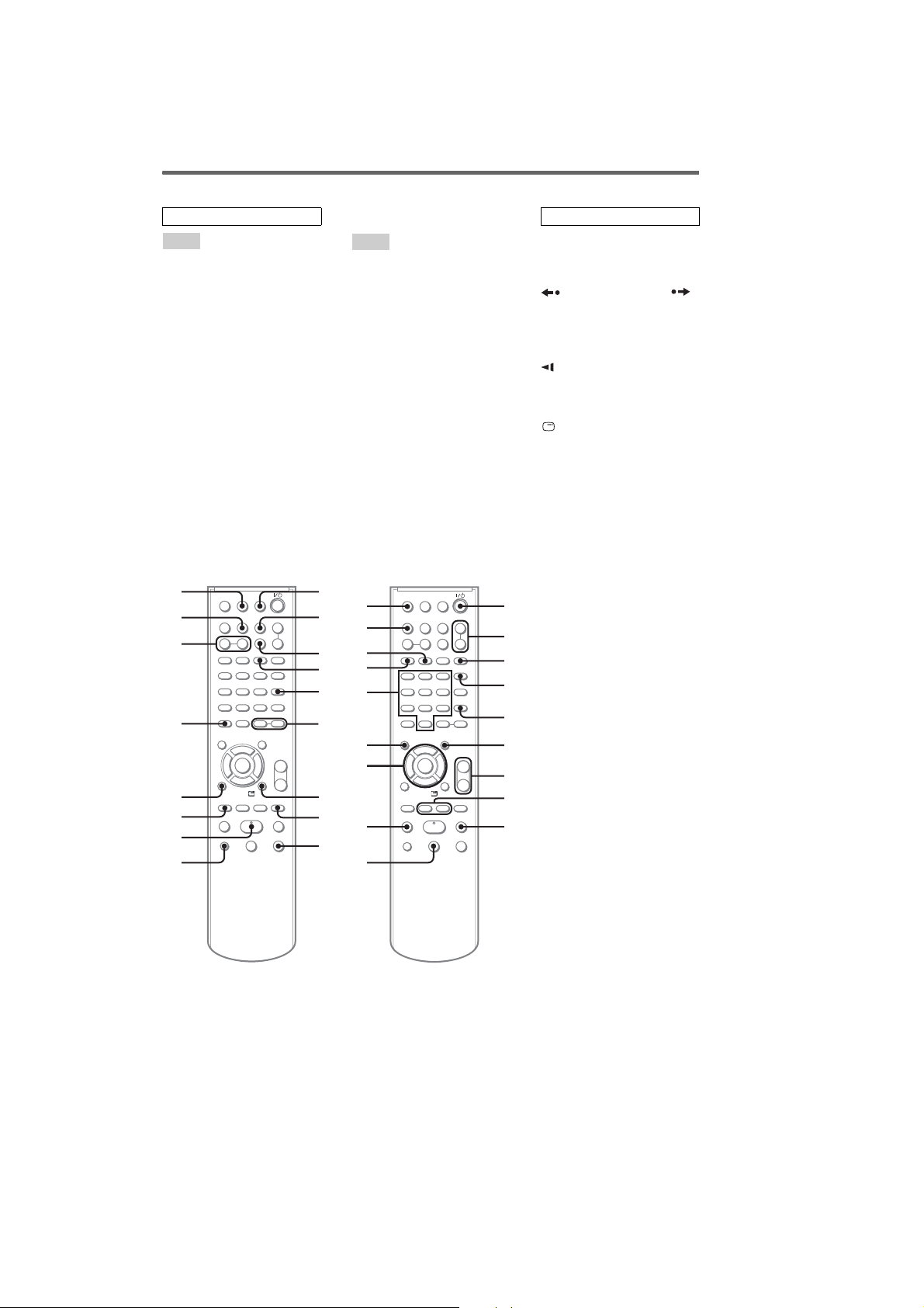
Remote control
ALPHABETICAL ORDER
A – Q
ALBUM +/– wf (18, 68)
ANGLE 5 (49)
AUDIO 4 (35, 57, 70)
CLEAR es (14, 20, 21, 23, 28,
33, 43)
DISC SKIP w; (18, 21)
DISPLAY qj (63, 65)
ENTER qs ( 14, 23, 20, 21, 23, 24,
27, 29, 32, 33, 34, 37, 45, 50,
59, 61, 62, 77)
FM MODE ws (51)
FUNCTION +/– 2 (14, 17, 50,
51)
KARAOKE MODE qg (57)
KARAOKE PON qh (59)
MENU 6 (23, 26, 27, 29, 31, 50)
Number buttons* qf (24, 46)
PICTURE NAVI 3 (28, 34)
PRESET + wh (51)
PRESET – e; (51)
eg
ef
ed
es
ea
e;
wl
+
++
+–
2
#
+–
V
bB
+
v
O
.>
yxmM
–
C
c
z
z
<
<
y
H
X
wk
R – Z
REPEAT ws (22)
SLEEP qk (61)
SOUND FIELD wa (55, 70)
SUBTITLE wd (49)
THEATRE SYNC ql (68)
TIMER MENU eg (14, 61, 62)
TIME/TEXT ef (64, 65)
TOP MENU qd (23)
TUNING + 9 (50, 51)
TUNING – qa (50, 51)
TV wk (68)
TV CH + wh (68)
TV CH – e; (68)
TV/VIDEO qk (68)
TV VOL +/–* 7 (68)
VOLUME +/–* 7 (44, 61)
ql
qk
w;
wa
ws
wd
qj
qh
qg
qf
2
wf
qd
qs
wg
wh
qa
O
.>
mM
y
wj
q;
#
V
bB
v
C
c
z
z
<
<
H
Xx
BUTTON DESCRIPTIONS
?/1 (power)
1 (10, 61, 68, 77)
TV ?/1 1 (68)
REPLAY/ADVANCE /
c STEP/STEP C 8 (18)
SLOW y 9 (18)
M (fast forward) 9 (18, 52)
X (pause) q; (18, 52)
SLOW qa (18)
m (rewind) qa (18, 52)
M/m/</, qs (14, 20, 37, 59,
61, 77)
DISPLAY wg (21, 45, 65, 67)
> (go forward) wh (18)
x (stop) wj (52)
. (go back) e; (18)
H (play)* wl (17, 39)
O RETURN ea (24)
-/-- es
KEY CONTROL
#/2
ed (59)
*The H, number 5 and
VOLUME + (TV VOL +)
buttons have tactile dots. Use
the tactile dots as references
1
+
–
when operatihng the system.
2
3
4
5
+–
6
+
7
–
8
y
9
10
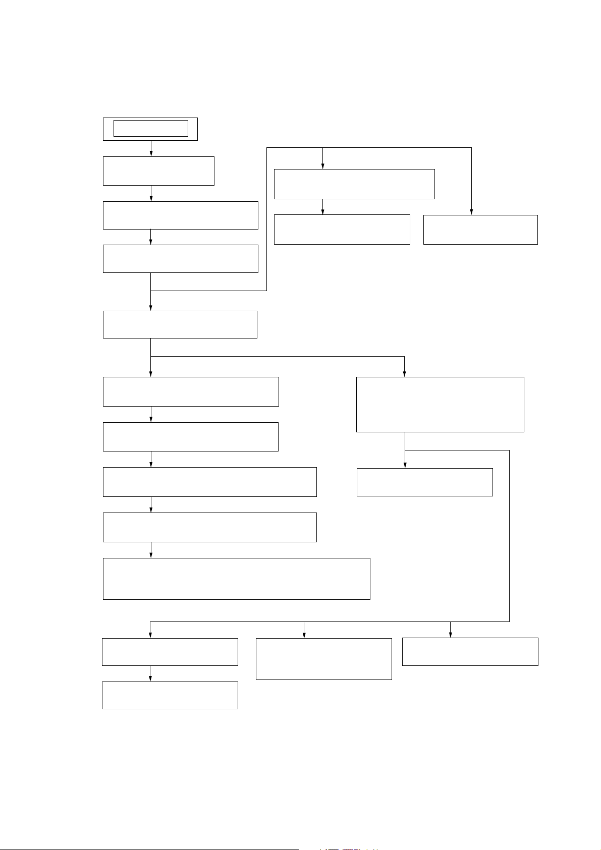
Note : Disassemble the unit in the order as shown below.
SET
3-1. CASE
(Page 12)
3-2. LOADING PANEL ASSY
(Page 12)
3-3. FRONT PANEL SECTION
(Page 13)
HCD-GNZ7D/GNZ8D/GNZ9D
SECTION 3
DISASSEMBLY
3-5. TAPE MECHANISM DECK
(Page 14)
3-7. JACK BOARD
(Page 15)
3-6. PANEL BOARD
(Page 14)
3-4. DVD BLOCK SECTION
(Page 13)
3-8. BACK PANEL SECTION
(Page 15)
3-9. BOARDS SECTION
(Page 16)
3-10. AUDIO BOARD (HCD-GNZ8D/GNZ9D)
(Page 16)
3-11. AUDIO BOARD (HCD-GNZ7D7)
(Page 17)
3-12. SURROUND AMP BOARD (HCD-GNZ8D/GNZ9D),
SUBWOOFER BOARD (HCD-GNZ9D)
(Page 17)
3-13. DVD MECHANISM BLOCK,
3-14. PICK-UP UNIT
VIDEO BOARD,
DMB10 BOARD
(Page 18)
(Page 18)
3-17. MOTOR (TB) BOARD
(Page 20)
3-18. MOTOR (LD) BOARD
(Page 20)
3-15. SW BOARD,
DRIVER BOARD
(Page 19)
3-16. SENSOR BOARD
(Page 19)
11
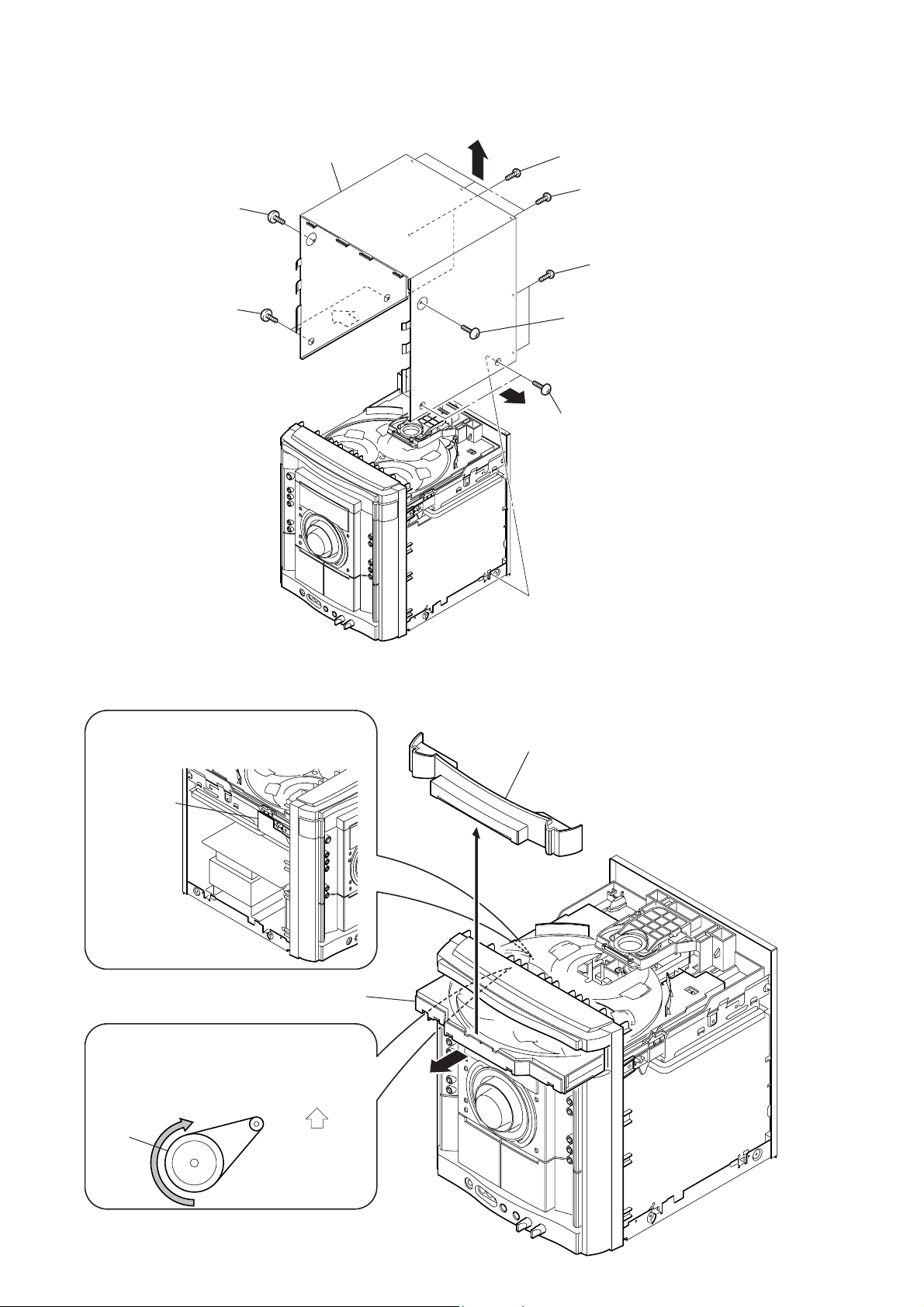
HCD-GNZ7D/GNZ8D/GNZ9D
Note : Follow the disassembly procedure in the numerical order given.
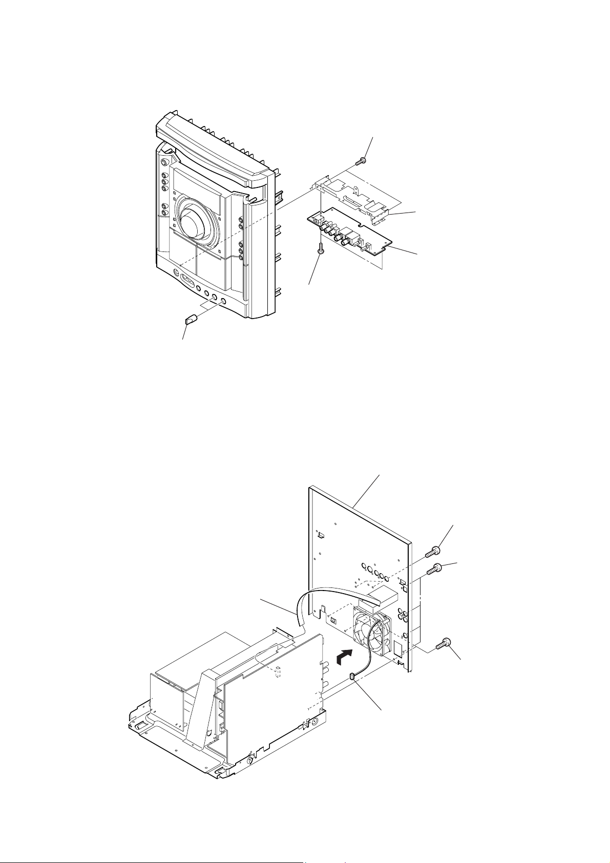
3-1. CASE
4
screw
(case 3 TP2)
3
two screws
(case 3 TP2)
0
case
8
9
8
6
two screws (+BVTT 3
5
three screws
(+BVTT 3
7
two screws
(+BVTT 3
2
screw
(case 3 TP2)
1
two screws
(case 3 TP2)
×
×
×
6)
6)
6)
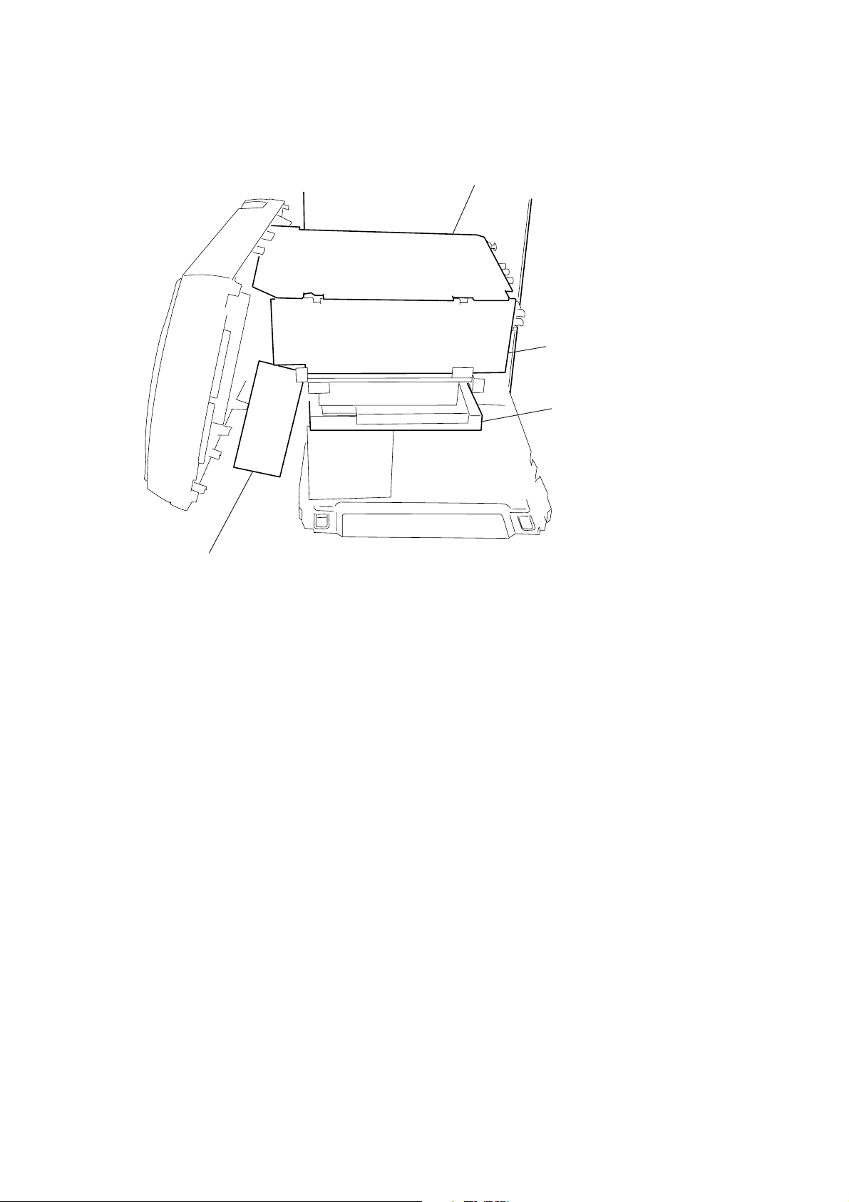
3-2. LOADING PANEL ASSY
1
The DVD mechanism block has a cover.
So the pulley may not be rotated unless
the cover is opened.
cover (B-CDM)
3
CD mechanism deck (CDM74HF)
2
Turn the pulley to the direction of arrow.
Pull-out the disc tray.
Front panel side
4
5
loading panel assy
12
pulley
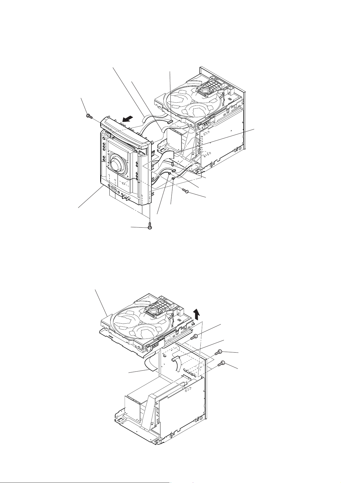
3-3. FRONT PANEL SECTION
)
1
9
screw
(+BVTP 3
×
10)
CN005 (13 core)
2
CN102 (13 core)
qa
3
CN203 (9P)
5
CN751 (10P)
HCD-GNZ7D/GNZ8D/GNZ9D
4
CN752 (29 core
qd
front panel section
8
four screws (+BVTT 3
3-4. DVD BLOCK SECTION
7
DVD block section
6
CN602 (8P)
0
screw
qs
CN1002 (4P)
7
CN601 (3P)
×
6)
(+BVTP 3
4
×
10)
3
two
screws
(+BVTT 3
6
CN851 (12P)
1
(+BVTT 3
×
10)
three
screws
×
10)
5
CN301 (17 core)
2
three
(+BVTT 3
screws
×
6)
13
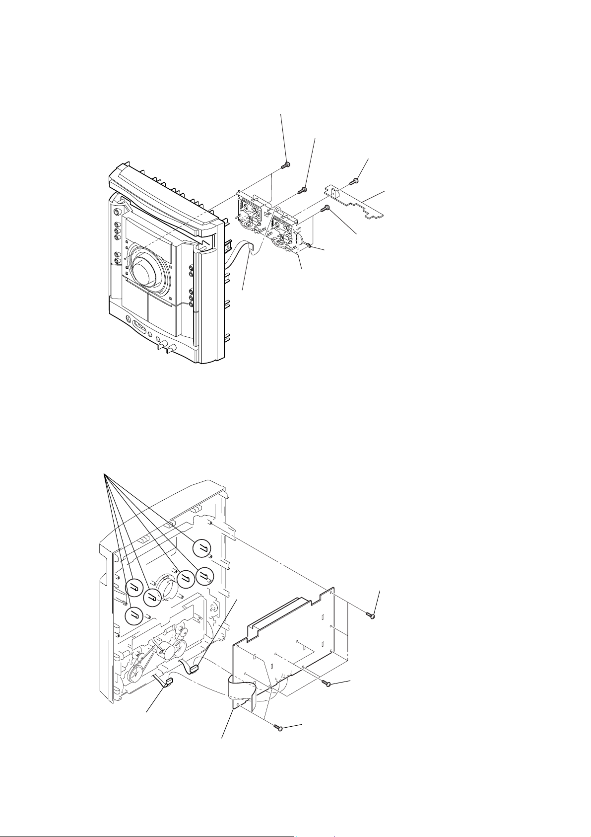
HCD-GNZ7D/GNZ8D/GNZ9D
)
3-5. TAPE MECHANISM SECTION
1
connector
4
two
screws
(+BVTP 2.6 (3CR))
6
screw
(+BVTP 2.6 (3CR))
clamp
7
tape mechanism deck
2
screw
(+BVTP 2.6 (3CR))
3
TEMP
board
5
two
screws
(+BVTP 2.6 (3CR))
3-6. PANEL BOARD
4
six
claws
6
CN151 (7P)
1
five
screws
(+BVTP 2.6 (3CR)
2
two
screws
(+BVTP 2.6 (3CR))
14
5
CN152 (5P)
7
PA NEL board
3
three
(+BVTP 2.6 (3CR))
screws
3-7. JACK BOARD
)
)
3
two screws
(+BVTT 3
2
two
screws
(+BVTP 2.6 (3CR))
×
6)
HCD-GNZ7D/GNZ8D/GNZ9D
4
bracket (TC-JACK
5
JACK board
1
two mic knobs
3-8. BACK PANEL SECTION
1
CN753 (9P)
7
back panel section
3
two
screws
(+BVTT 3
2
four
screws
(+BVTP 3
×
×
6)
10
5
6
CN754 (2P)
4
four
screws
(+BVTT 3
×
6)
15
HCD-GNZ7D/GNZ8D/GNZ9D
d
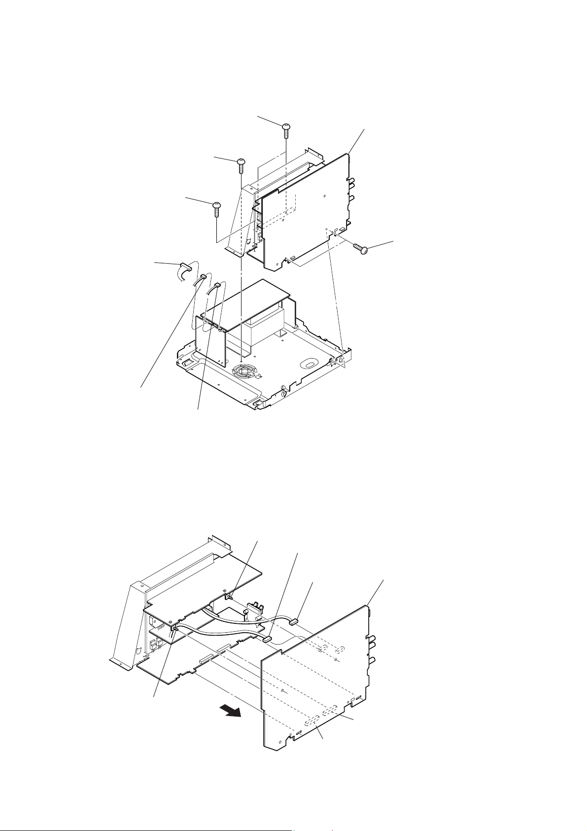
3-9. BOARDS SECTION
7
two
screws
(+BVTT 3
6
5
screw
(+BVTT 3
3
CN914 (10P)
screw
(+BVTT 3
×
6 (sumitite)
×
6 (sumitite)
×
6 (sumitite)
8
boards section
4
(+BVTT 3
two
screws
×
6)
2
CN915 (4P)
1
CN913 (3P)
(HCD-GNZ8D/GNZ9D)
3-10. AUDIO BOARD (HCD-GNZ8D/GNZ9D)
1
claw
4
(HCD-GNZ9D)
CN303 (6P)
5
CN302 (5P)
6
AUDIO boar
16
2
claw
3
CN201
CN202
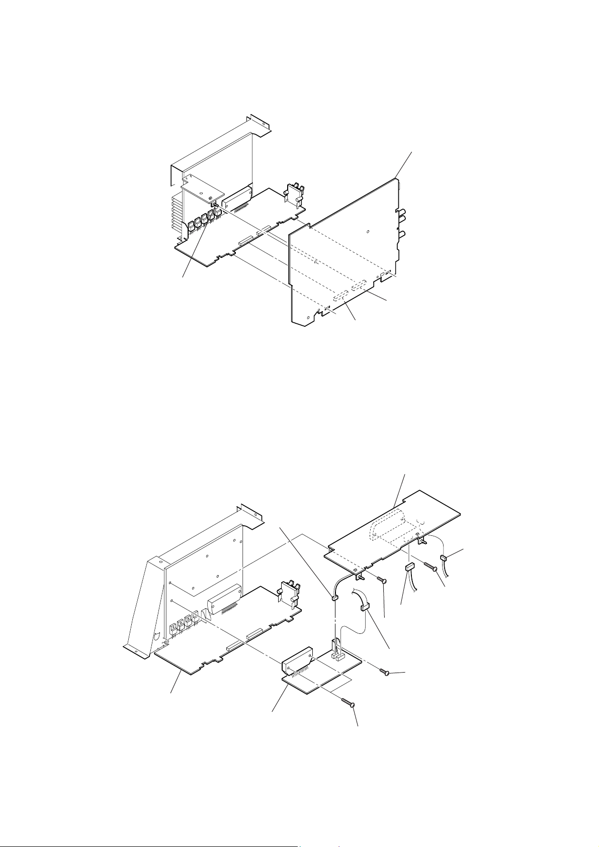
3-11. AUDIO BOARD (HCD-GNZ7D)
d
)
1
claw
HCD-GNZ7D/GNZ8D/GNZ9D
2
AUDIO boar
CN201
CN202
3-12. SURROUND AMP BOARD (HCD-GNZ8D/GNZ9D), SUBWOOFER BOARD (HCD-GNZ9D)
6
SURROUND AMP board
5
CN603 (2P)
2
CN572 (3P
4
two
screws
1
CN502 (6P)
3
screw
(+BVTP 3
(+BVTP 3
× 8
)
×
16)
FRONT AMP board
0
SUBWOOFER board
7
CN602 (4P)
8
two
(+BVTP 3
screws
9
screw
(+BVTP 3
×
16)
× 8
)
17
HCD-GNZ7D/GNZ8D/GNZ9D
)
)
3-13. DVD MECHANISM BLOCK, VIDEO BOARD, DMB10 BOARD
qj
DVD mechanism block
qf
screw
qs
DMB10 board
qa
two
screws
(+BVTT 3
2
CN401 (5P)
×
(+BVTP 3
6)
×
8)
8
CN201 (6P)
0
two
(+BVTT 3
9
CN101 (24 core)
qg
4
claw
screws
×
6)
Note : Be shor t-circuited of the land of optical pick-up when CN101
is done in pulling out.
qh
bracket (DVD)
1
CN801 (13P)
7
REINFORCE (CDM) board
6
three
(+BVTT 3
qd
screw
(+BVTP 3
5
VIDEO board
two
screws
3
(+BVTT 3
×
×
6)
screws
8)
×
6
3-14. PICK-UP UNIT
3
two insulator screws
6
pick-up unit
7
holder (310)
5
two insulators
2
two insulator screws
4
two insulators
1
floating
(+PTPWH M2.6
screw
18
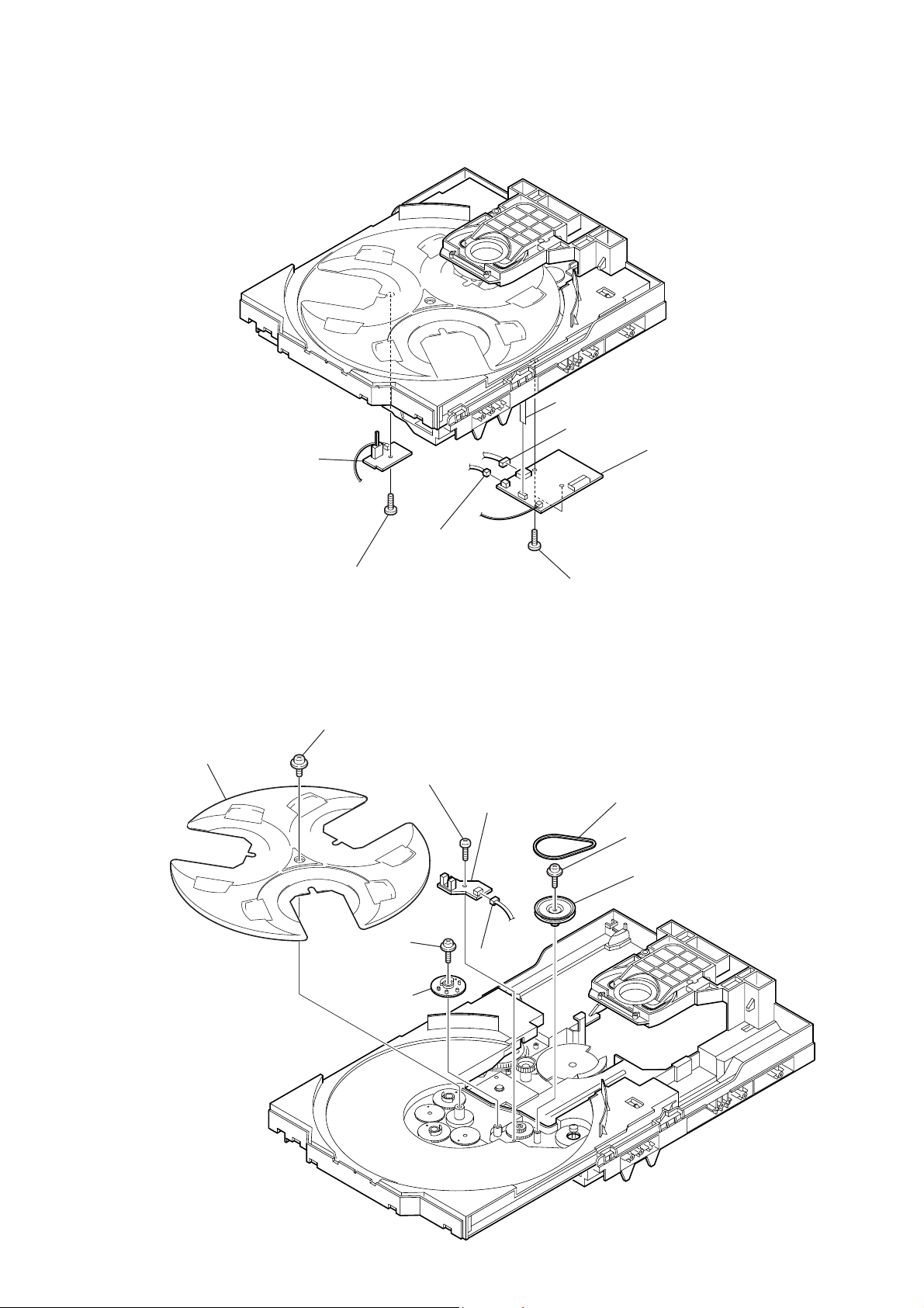
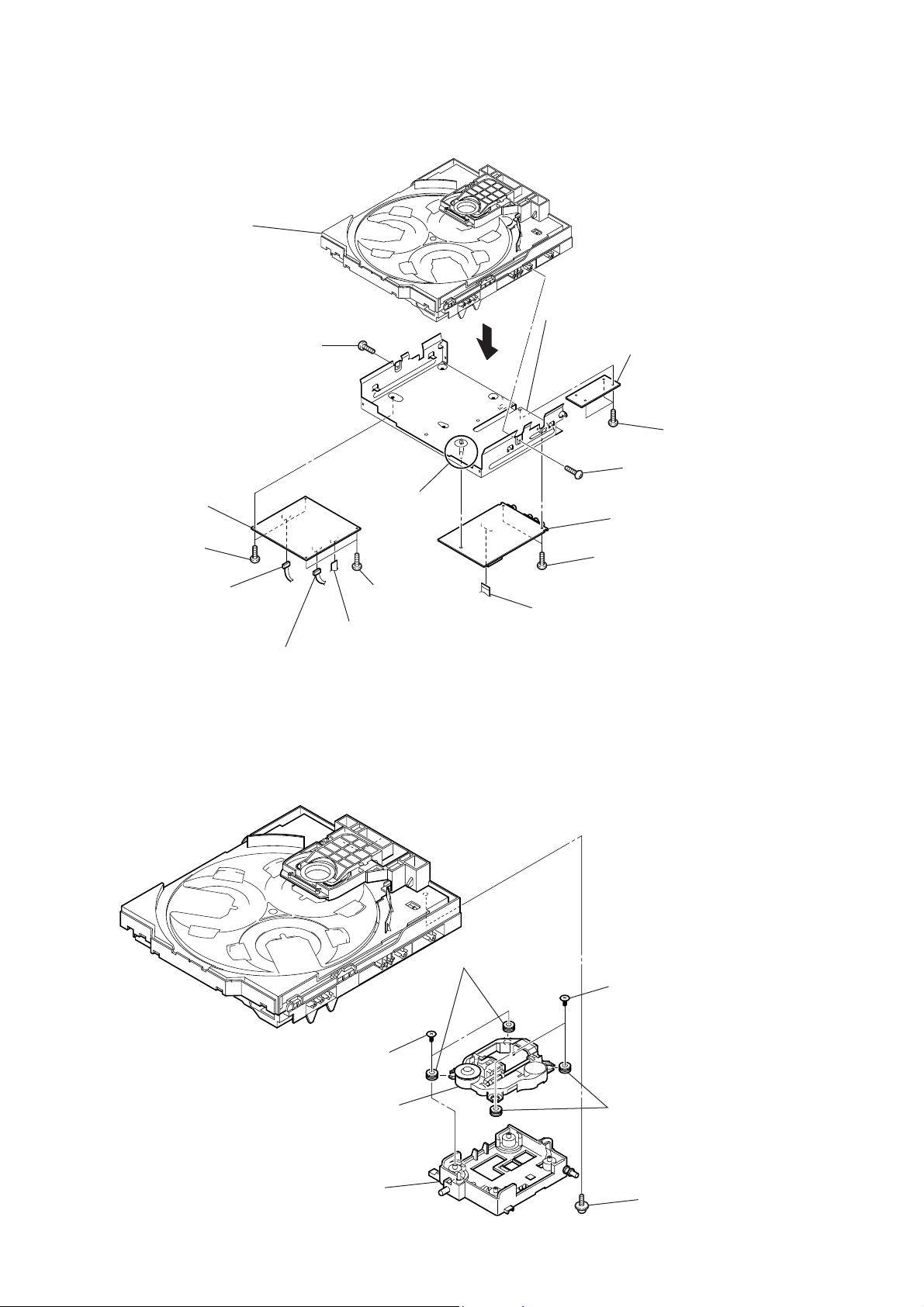
3-15. SW BOARD, DRIVER BOARD
d
2
SW board
HCD-GNZ7D/GNZ8D/GNZ9D
7
CN702 (flat type)
4
CN703
6
DRIVER boar
3-16. SENSOR BOARD
2
tray
1
screw
(+BTTP (M2.6))
1
floating
(+PTPWH M2.6)
6
floating
(+PTPWH M2.6)
screw
8
screw
(+BTTP (M2.6))
screw
3
CN704
0
9
SENSOR board
CN731
5
two
screws
(+BTTP (M2.6))
3
belt (table)
4
floating
(+PTPWH M2.6)
5
pulley (table)
screw
7
gear (geneva)
19
HCD-GNZ7D/GNZ8D/GNZ9D
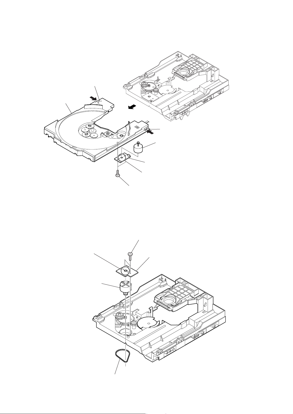
3-17. MOTOR (TB) BOARD
2
table assy
stopper
1
2
stopper
6
table motor assy (M741)
3-18. MOTOR (LD) BOARD
4
Remove the two solderings of motor.
5
loading motor assy (M751)
4
MOTOR (TB) board
5
Remove the two solderings of motor.
3
two
screws
(+BTTP (M2.6))
2
two
screws
(+BTTP (M2.6))
3
MOTOR (LD) board
20
1
belt (loading)

SECTION 4
TEST MODE
HCD-GNZ7D/GNZ8D/GNZ9D
[Cold Reset]
• The cold reset clears all data including preset data stored in the
RAM to initial conditions. Execute this mode when returning
the set to the customer.
Procedure:
1. Press three buttons of x , [DISPLAY] and [DISC 1]
simultaneously.
2. The message “COLD RESET” is displayed, and the set is reset.
[Tuner Step Change]
•A step of AM channels can be changed over between 9 kHz and
10 kHz.
Procedure:
1. Press the
to TUNER/BAND “AM”.
2. Press the `/1 button to turn the power OFF.
3. Press two buttons of [TUNING +] and `/1 simultaneously, and
the message changes to “AM 9 k STEP” or “AM 10 k STEP”,
and thus the channel step is changed over.
[TV/SAT Function Change]
• Change of function TV or SAT (also the input level changes).
Procedure:
1. Press the
2. Press two buttons of [TV/SAT] and `/1 simultaneously, and
the message changes to “SAT” or “TV”, and thus the channel
step is changed over.
[Color System Change]
Procedure:
1. Press the
2. Press two buttons of X and `/1 simultaneously.
3. The message “COLOR NTSC” or “COLOR PAL” is displayed.
[Disc Tray Lock]
The disc tray lock function for the antitheft of a demonstration disc
in the store is equipped.
Setting Procedure :
1. Press the
2. Press two buttons of x and Z simultaneously for five seconds.
3. The message “LOCKED” is displayed, and the tray is locked.
Releasing Procedure :
1. Press two buttons of x and Z simultaneously for five seconds.
2. The message “UNLOCKED” is displayed, and the tray is
unlocked.
Note: When the message “LOCKED” is displayed, the tray lock is
[Progressive Change]
Procedure:
1. Press the
2. Press two buttons of [DVD] and [DISPLAY] simultaneously.
[Panel Test Mode]
•This mode is used to check the fluorescent indicator tube, LEDs,
keyboard, volume and phones.
Enter The Panel Test Mode
Procedure:
1. Press three buttons of
neously.
2. LEDs and fluorescent indicator tube are all turned on.
Model Information
Procedure:
1. It puts it into the start of the panel test mode.
2. Press the [DIRECTION] button, the mode change model name
or destination display.
Key Test Mode
Procedure:
1. It puts it into the start of the panel test mode.
2. Press the Y button, the mode change key test mode.
`/1 button to turn the power ON, and set the function
`/1 button to turn the power ON.
`/1 button to turn the power ON.
?/1 button to turn the power ON.
not released by turning power ON/OFF with the ?/1 button.
`/1 button to turn the power ON.
x , [DISPLAY] and [DISC 2] simulta-
VA CS Display
Procedure:
1. It puts it into the start of the panel test mode.
2. Press the
The message “VACS 0+0” is displayed.
Ve rsion Display
Procedure:
1. It puts it into the start of the panel test mode.
2. Press the [DIRECTION] button, the mode change version display.
Press the [DISPLAY] button, the mode change version or days is
displayed.
3. You can exit the Test Mode when you press three buttons of X ,
[DISPLAY] and [DISC 2] simultaneously.
[Common Test Mode]
•This mode is used to check operations of the respective sections
of Amplifier and Tape.
Procedure:
•To enter MC Test Mode
1. Press the `/1 button to turn the power ON.
2. Press three buttons of x , [DISPLAY] and [DISC 3] simulta-
neously.
* Check of Amplifier
Initial settings: Input , TV
• When you press the [EQ BAND/MEMORY] button, the message
“GEQ FLAT” is displayed, and the entire band of the graphic
equalizer is set to the center level.
•When [VOLUME] control knob is turned clockwise even slightly,
the sound volume increases to is maximum and the message
“VOLUME MAX” is displayed for two seconds, then the display
returns to the original display.
• When [VOLUME] control knob is tuned counter-clockwise even
slightly, the sound volume decreases to its minimum and the
message “VOLUME MIN” is displayed for two seconds, then
the display returns to the original display.
• Whenever you press the [GROOVE] button, it toggles between
“VACS ON” and “VACS OFF” so that you can switch ON or
OFF of VACS.
*To return to normal mode again.
1. When you want to exit this mode, press the
2. The cold reset is enforced at the same time.
[DVD and CD Ship Mode (No Memory Clear)]
•This mode moves the position to the position durable to
vibration. Use this mode when returning the set to the customer
after repair.
Procedure:
1. Press the
2. Press two buttons of x and [DISC SKIP] simultaneously.
3. After the “STANDBY” display blinks 15 times, the message
“LOCK” is displayed, and the DVD ship mode is set.
[DVD and CD Ship Mode (Memory Clear)]
•This mode moves the pickup to the position durable to
vibration. Use this mode when returning the set to the customer
after repair.
Procedure:
1. Press the
2. Press three buttons of x , [DISPLAY] and [DIRECTION] simul-
taneously.
3. After the “STANDBY” display blinks 15 times, the message
“LOCK” is displayed, and the DVD ship mode is set.
X button, the mode change VACS display.
EQ , FLAT
Mode , MUSIC
VA C S , OFF
`/1 button.
`/1 button to turn the power ON.
button to turn the power ON.
`/1
21
HCD-GNZ7D/GNZ8D/GNZ9D
Ver. 1.1
DVD SECTION
[TEST DISC LIST]
Be sure to use the DVD disc that matches the signal standards of
your region.
• CD
YEDS-18 (Part No.: 3-702-101-01)
PATD-012 (Part No.: 4-225-203-01)
• DVD SL (Single Layer)
NTSC : HLX-503 (Part No.: J-6090-069-A)
HLX-504 (Part No.: J-6090-088-A)
PAL : HLX-506 (Part No.: J-6090-077-A)
• DVD DL (Dual Layer)
NTSC : HLX-501 (Part No.: J-6090-071-A)
HLX-505 (Part No.: J-6090-089-A)
PAL : HLX-507 (Part No.: J-6090-078-A)
4-1. GENERAL DESCRIPTION
The Mirror Time and IOP measurement allows you to make
diagnosis and adjustment simply by using the remote commander
and monitor TV. The instructions, diagnosis results, etc. are given
on the on screen display (OSD).
The Mirror Time and IOP measurement is required is such events
where servicing a DVD-Player includes changing the Base Unit
(BU). For each new BU to be used with a certain MV-044 board,
Mirror Time and IOP measurement need to be carried out.
4-2. ST ARTING TEST MODE
Press three buttons
with the DVD player in standby mode.
The Test Mode starts, then the menu shown below will be
displayed on the TV screen.
0. External Chip Check
1. Servo Parameter Check
2. Drive Manual Operation
3. Emergency History
4. Version Information
5. Video Level Adjustment
Model Name : GVLXD_XX
IF-con : V
Syscon : Ver.
x , A and [VOLUME +] simultaneously
Remocon Diagnosis Menu
er. xx.xx (xxxx)
x.xxx
4-4. MIRROR TIME ADJUSTMENT
To enter Mirror Time Adjustment, press 5 “R” button on the remote
commander. The screen will appear as below.
MIRR time Adjust Menu
1. CD MIRR time Check:
2. DVD MIRR time Check:
3. Threshold:
4. Save to EEPROM
5. Default set MIRR time
[Open] Tray open [Close] Tray close
[0] Return to previous menu
There are five main commands in the Mirr time Adjust menu as
shown in the figure above. The functions of each command are
described in the following page.
1. CD MIRR time Check
This command checks the Mirror time value for CD disc.
2. DVD MIRR time Check
This command checks the Mirror time value for DVD disc.
3. Threshold
This command displays the threshold value between CD and DVD
mirror time.
4. Save to EEPROM
This command saves an adjusted mirror time value to the EEPR OM.
5. Default set MIRR time
This command will set CD and DVD mirror time to firmware def ault
value.
[Open] / [Close]
Pressing the A button controls the tray for disc change
during mirror time adjustment.
[0] Return to previous menu
Press 0 “R” button to return to previous menu.
4-4-1. EXECUTING MIRROR TIME ADJUSTMENT
In order to execute mirror time adjustment, the following standard
procedures must be followed.
The menu above is the Remocon Diagnosis Menu screen which
consists of six main function. At the bottom of the menu screen,
the model name and IF-con version. To enter Mirror Time
Adjustment menu, press button 2 “R” on the remote commander
to enter Drive Manual Operation menu. To exit from the Test Mode,
press the power button on the remote commander.
4-3. DRIVE MANUAL OPERATION
The Drive Manual Operation menu consists of five main
function. By pressing 2 “R” button on the remote commander in
the Remocon Diagnosis Menu, the screen will appear as below.
Drive Manual Operation
1. Servo Control
2. Track/Layer Jump
3. Manual Adjustment
4. Tray Aging Mode
5. MIRR time Adjust
0. Return to Top Menu
22
(1) In standby mode, press three buttons x , A and [VOLUME +]
simultaneously.
(2) Select “2. Drive Manual Operation”.
Remocon Diagnosis Menu
0. External Chip Check
1. Servo Parameter Check
2. Drive Manual Operation
3. Emergency History Check
4. Version information
5. Video Level Adjustment
Model : GVLXD_xx
IF-con : Ver. xx.xx (xxxx)
Syscon : Ver. x.xxx
HCD-GNZ7D/GNZ8D/GNZ9D
(3) Select “5. MIRR time Adjust”.
Drive Manual Operation
1. Servo Control
2. Track/Layer Jump
3. Manual Adjustment
4. Mecha test mode
5. MIRR time Adjust
0. Return to Top Menu
(4) Select “5. Default set MIRR time”.
MIRR time Adjust Menu
1. CD MIRR time Check:
2. DVD MIRR time Check:
3. Threshold:
4. Save to EEPROM:
5. Default set MIRR time:
[Open] Tray open [Close] Tray close
[0] Return to previous menu
(5) Select “3. Threshold”.
(6) Confirm the number. If it is 7D, go to next step. If it is any
other value, return to step 4.
MIRR time Adjust Menu
(14) Confirm the same values are displayed. If it is not same,
return to step 7.
MIRR time Adjust Menu
1. CD MIRR time Check:
2. DVD MIRR time Check: XX XX
3. Threshold:
4. Save to EEPROM:
5. Default set MIRR time:
[Open] Tray open [close] Tray close
[0] Return to previous menu
(15) Push A button to eject tray.
(16) Take out HLX-504 and insert Test Disc YEDS-18 into
tray.
(17) Push A button to close tray.
(18) Push “1. CD MIRR time check”.
(19) Wait for HEX number to display.
(20) Confirm the number, if YY is 5A ~ E8, proceed with next
step. If no, return to 15.
MIRR time Adjust Menu
1. CD MIRR time Check:
2. DVD MIRR time Check:
3. Threshold: 7D
4. Save to EEPROM:
5. Default set MIRR time:
[Open] Tray open [Close] Tray close
[0] Return to previous menu
(7) Push A button to eject tray.
(8) Insert Test Disc HLX-504 into tray.
(9) Push A button to close tray.
(10) Push “2. DVD MIRR time Check”.
(11) Wait for HEX number to display.
(12) Confirm the number, if XX is 28 ~ 70, proceed with next
step. If no, return to 8.
MIRR time Adjust Menu
1. CD MIRR time Check:
2. DVD MIRR time Check: xx xx
3. Thereshold:
4. Save to EEPROM:
5. Default set MIRR time:
[Open] tray open [close] Tray close
[0] Return to previous menu
1. CD MIRR time Check: yy YY
2. DVD MIRR time Check: XX XX
3. Threshold:
4. Save to EEPROM:
5. Default set MIRR time:
[Open] Tray open [close] Tray close
[0] Return to previous menu
(21) Push “4. Save to EEPROM”.
(22) Confirm the same values are displayed. If it is not the
same, return to step 15.
MIRR time Adjust Menu
1. CD MIRR time check: YY YY
2. DVD MIRR time check: XX XX
3. Threshold:
4. Save to EEPROM:
5. Default set MIRR time:
[Open] Tray open [close] Tray close
[0] Return to previous menu
(23) Push A button to eject tray.
(24) Remove Test Disc YEDS-18 from tray.
(25) Push A button to close tray.
(26) Press 0 “R” button to the Drive Manual Operation menu.
(13) Push “4. Save to EEPROM”.
(27) Press 0 “R” button to return to the Remocon Diagnosis
Menu.
(28) Press the
?/1 button to switch OFF set.
23
HCD-GNZ7D/GNZ8D/GNZ9D
4-5. EXECUTING IOP MEASUREMENT
In order to execute mirror time adjustment, the following standard
procedures must be followed.
(1) In standby mode, press three buttons x , A and
[VOLUME +] simultaneously.
Remocon Diagnosis Menu
0. External Chip Check
1. Servo Parameter Check
2. Drive Manual Operation
3. Emergency History Check
4. Version information
5. Video Level Adjustment
Model : GVLXD XX
IF-con Ver : XX.XX (XXXX)
Syscon Ver : X.XX
(2) Select “2. Drive Manual Operation” by pressing the 2 “R”
button on the remote commander. The screen will appear as
below.
Drive Manual Operation
1. Servo Control
2. Track/Layer Jump
3. Manual Adjustment
4. Tray Aging Mode
5. MIRR time adjust
0. Return to top Menu
(5) Wait until a hexadecimal number appear.
Manual Adjust
1. Track Balance Adjust:
2. Track Gain Adjust:
3. Focus Balance Adjust:
4. Focus Gain Adjust:
5. Eq Boost Adjust:
6. Iop. 5B:
7. TRV. Level:
8. S curve(FE) Level:
9. RFL(PI) Level:
0. MIRR Time:
Change Value
[0] Return to previous menu
(6) Convert each data from hexadecimal to decimal using
conversion table.
(7) Substract between these two values.
(8) If the remainder is smaller than 93 (decimal), then it is
OK. However if the value is higher than 93, then the BU
is defective and need to be change.
(9) Press RETURN “R” button to return back to previous menu.
(10) Press 0 “R” button to return to Top Menu and power OFF
the DVD Player.
(3) Select “3. Manual Adjustment” by pressing the 3 “R” button
on the remote commander. The screen will appear as below.
Manual Adjust
1. Track Balance Adjust:
2. Track Gain Adjust:
3. Focus Balance Adjust:
4. Focus Gain Adjust:
5. Eg boost Adjust:
6. Iop:
7. TRV. Level:
8. S curve(FE) Level:
9. RFL(PI) Level:
0. MIRR Time:
o O Change Value
[RETURN] Return to previous menu
(4) Select Iop by pressing 6 “R” button on the remote commander.
24
SECTION 5
MECHANICAL ADJUSTMENTS
Precaution
1. Clean the following parts with a denatured alcohol-moistened
swab:
record/playback heads pinch rollers
erase head rubber belts
capstan idlers
2. Demagnetize the record/playback head with a head
demagnetizer.
3. Do not use a magnetized screwdriver for the adjustments.
4. After the adjustments, apply suitable locking compound to the
parts adjusted.
5. The adjustments should be performed with the rated power
supply voltage unless otherwise noted.
Torque Measurement
Mode
FWD
FWD
back tension
REV
REV
back tension
FF/REW
FWD tension
REV tension
Torque meter
CQ-102C
CQ-102C
CQ-102RC
CQ-102RC
CQ-201B
CQ-403A
CQ-403R
Meter reading
3.06 N • m to 6.96 N • m
31 to 71 g • cm
(0.43 – 0.98 oz • inch)
0.19 N • m to 0.58 N • m
2 to 6 g • cm
(0.02 – 0.08 oz • inch)
3.06 N • m to 6.96 N • m
31 to 71 g • cm
(0.43 – 0.98 oz • inch)
0.19 N • m to 0.58 N • m
2 to 6 g • cm
(0.02 – 0.08 oz • inch)
6.96 N • m to 14.02 N • m
71 to 143 g • cm
(0.98 – 1.99 oz • inch)
9.80 N • m
100 g or more
(3.53 oz or more)
9.80 N • m
100 g or more
(3.53 oz or more)
HCD-GNZ7D/GNZ8D/GNZ9D
25
HCD-GNZ7D/GNZ8D/GNZ9D
)
Ver. 1.1
ELECTRICAL ADJUSTMENTS
SECTION 6
DVD SECTION
When the base unit is replaced, perform the adjustment and the
measurement as shown below in this order.
1) MIRROR TIME ADJUSTMENT (See page 22)
2) EXECUTING IOP MEASUREMENT (See page 24)
[TEST DISC LIST]
Be sure to use the DVD disc that matches the signal standards of
your region.
• CD
YEDS-18 (Part No.: 3-702-101-01)
PATD-012 (Part No.: 4-225-203-01)
• DVD SL (Single Layer)
NTSC : HLX-503 (Part No.: J-6090-069-A)
HLX-504 (Part No.: J-6090-088-A)
PAL : HLX-506 (Part No.: J-6090-077-A)
• DVD DL (Dual Layer)
NTSC : HLX-501 (Part No.: J-6090-071-A)
HLX-505 (Part No.: J-6090-089-A)
PAL : HLX-507 (Part No.: J-6090-078-A)
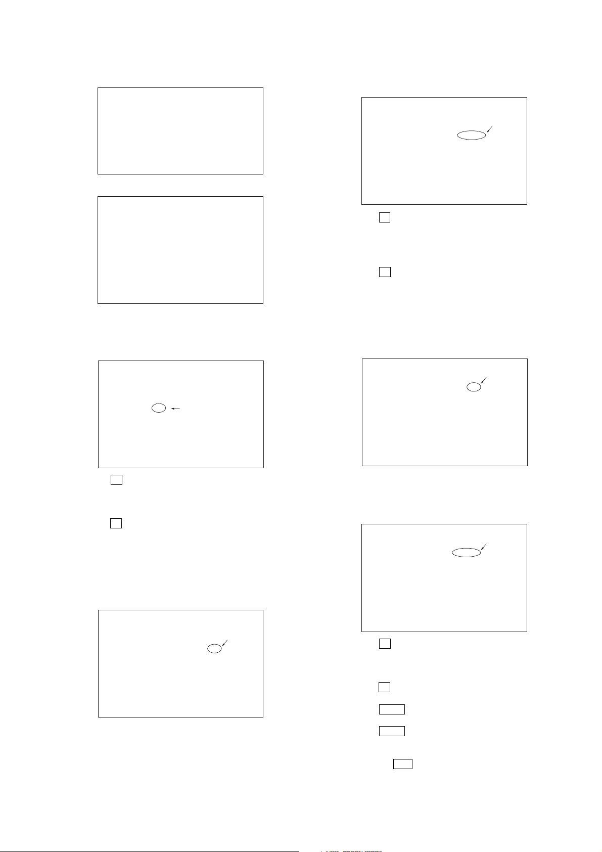
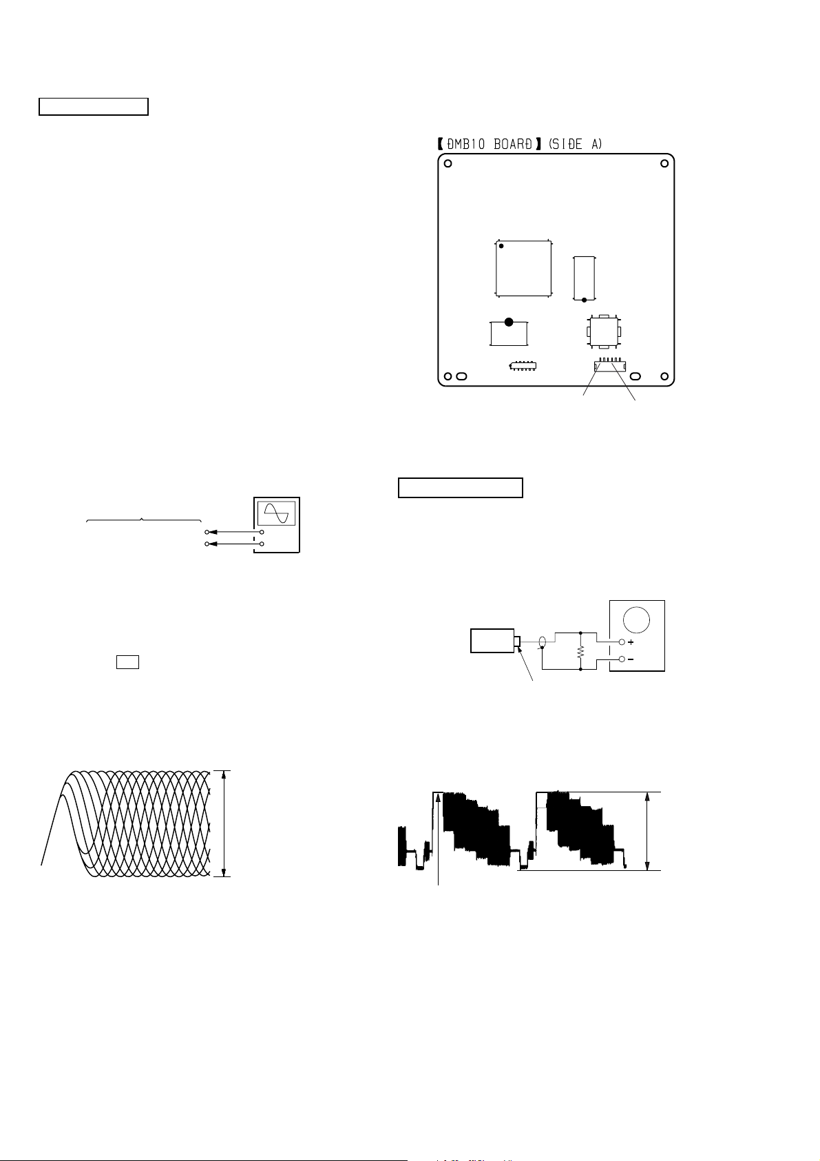
[RFMON Level Check]
Connection:
oscilloscope
DMB10 board
CN105 pin 6 (RFMON)
CN105 pin
3
(GND)
+
–
Checking Location: DMB10 board (Side A)
IC104
IC102
CN105
IC201
6
1
CN105 pin 3 (GND
IC101
CN106
CN105 pin 6 (RFMON)
VIDEO SECTION
Video Level Check (VIDEO BOARD)
Purpose
This adjustment is made to satisfy the NTSC standard, and if not
adjusted correctly, the brightness will be too large or small.
Procedure:
1. Connect an oscilloscope to CN105 pin 6 (RFMON) and
CN105 pin 3 (GND) on the DMB10 board.
2. Turn the power on.
3. Set the test disc (refer to the TEST DISC LIST) on the tray
and press H button to playback.
4. Confirm that oscilloscope waveform is clear and check
RFMON signal level is correct or not.
Note: A clear RFMON signal waveform means that the shape “◊” can be
clearly distinguished at the center of the waveform.
RFMON signal waveform
VOLT/DIV: 200 mV
TIME/DIV: 500 ns
level: 0.58 ± 1.23 Vp-p (DVD)
0.57 ± 1.1 Vp-p (CD)
oscilloscope
Ω
75
set
J802
VIDEO OUTPUT
Procedure:
1. Connect oscilloscope to VIDEO output.
2. Load a DVD reference disc playback.
3. Check the video signal level is 1.00±0.07Vp-p.
(WHITE 100%)
1.00 ± 0.07 Vp-p
26
HCD-GNZ7D/GNZ8D/GNZ9D
r
e
Ver. 1.1
DECK SECTION
0 dB=0.775 V
1. Demagnetize the record/playback head with a head
demagnetizer.
2. Do not use a magnetized screwdriver for the adjustments.
3. After the adjustments, apply suitable locking compound to the
parts adjust.
4. The adjustments should be performed with the rated power
supply voltage unless otherwise noted.
5. The adjustments should be performed in the order given in this
service manual. (As a general rule, playback circuit adjustment
should be completed before performing recording circuit
adjustment.)
6. The adjustments should be performed for both L-CH and RCH.
7. Switches and controls should be set as follows unless otherwise
specified.
•Test Tape
Tape Signal Used for
P-4-A063 6.3 kHz, –10 dB Azimuth Adjustment
Record/Playback Head Azimuth Adjustment
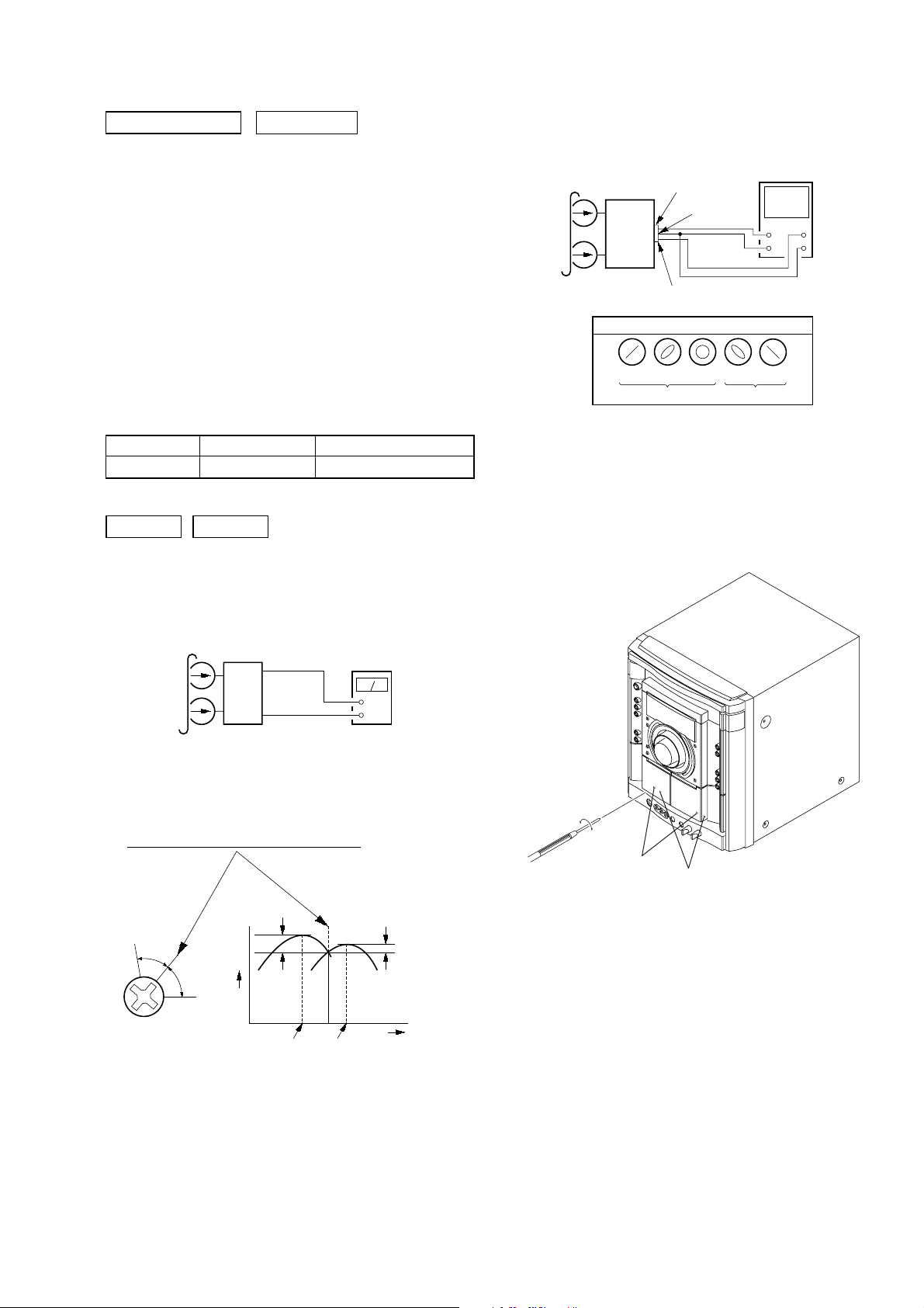
DECK A DECK B
Note: Perform this adjustments for both decks
Procedure:
1. Mode: Playback
3. Mode: Playback
test tape
P-4-A063
(6.3 kHz, –10 dB)
L-CH
AUDIO
board
IC201
R-CH
waveform of oscilloscope
in phase 45°90°135°180
pin 28
pin 38
L
R
pin 37
good
oscilloscop
V
wrong
H
°
4. After the adjustments, apply suitable locking compound to the
pats adjusted.
Adjustment Location: Playback Head (Deck A).
Record/Playback/Erase Head (Deck B).
test tape
P-4-A063
(6.3 kHz, –10 dB)
AUDIO board
IC201
Pin 28 (L-CH)
Pin 37 (R-CH)
set
AUDIO board
IC201
Pin 38 (GND)
level mete
+
–
2. Turn the adjustment screw and check output peaks. If the peaks
do not match for L-CH and R-CH, turn the adjustment screw
so that outputs match within 1dB of peak.
output
level
within
1dB
L-CH
peak
R-CH
peak
within
1dB
screw
position
L-CH
peak
screw
position
R-CH
peak
forward
forward
27

HCD-GNZ7D/GNZ8D/GNZ9D
SECTION 7
DIAGRAMS
• IC PIN Descriptions
IC101 M30392MEP-A00FPU (SYSTEM CONTROL) (PANEL BOARD (2/2))
Pin No. Pin Name I/O Pin Description
1 61537 CLK O TA device control serial clock signal output
2 61530 CLK O TA device control serial clock signal output
3TA DATA O TA device control serial data signal output
4STANDBY LED O Standby LED control signal output
5 VIDEO OUT SW O Video out switch control signal output “H”: VIDEO
6 VIDEO MUTE O Video mute signal output “L”: VIDEO
7 SIRCS I Remote control signal input
8VACS2 I VACS signal input
9 CN VSS — Connector ground pin
10 X CIN I Sub clock signal input (32.768 kHz)
11 X COUT O Sub clock signal output (32.768 kHz)
12 RESET I Reset signal input
13 XOUT O Main clock signal output (16 MHz)
14 VSS — Ground pin
15 X IN I Main clock signal input (16 MHz)
16 VCC1 — Power supply pin (+3.3 V)
17 P85 I Pull up (EVER+3.3 V)
18 ILLUMI 1/4 O Illumination on/off control signal output “H”: On
19 ST TUNED I ST tuned signal input
20 AC CUT I AC cut signal input
21 ILLUMI CTRL O Illumination control signal output
22 DVD POWER O DVD power supply control signal output
23 MTK RESET O MTK reset signal output
24 MTK BUSY O MTK busy signal output
25 I2C CLK I/O I2C serial clock signal input/output
26 I2C DATA I/O I2C serial data signal input/output
27 MTK OUT O MTK serial data signal output
28 MTK IN I MTK serial data signal input
29 MTK CLK I MTK serial clock signal input
30 MTK CS I MTK chip select signal input
31 to 43 G13 to G1 O Grid and segment control signal output
44 to 51 P1 to P8 O Grid and segment control signal output
52 VEE — Power supply pin
53 to 61 P9 to P17 O Grid and segment control signal output
62 VCC2 — Power supply pin (+3.3 V)
63 P18 O Grid and segment control signal output
64 VSS — Ground pin
65 to 67 P19 to P21 O Grid and segment control signal output
68 ST CE O Tuner chip enable signal output
69 ST DIN I Tuner data in signal input
70 ST DOUT O Tuner data out signal output
71 ST CLK O Tuner serial clock signal output
72 I/O VCC CONT O In/out power supply control signal output
73 I/O LATCH O In/out serial latch control signal output
74 WAKE UP0 I Wake up signal input
75 I/O CLK O In/out serial clock control signal output
76 I/O DI1 O In/out serial data control signal output
77 I/O RST O In/out reset signal output
78 TRG (B) O Tape mechanism logic (Trigger B) control signal output
79 TRG (A) O Tape mechanism logic (Trigger A) control signal output
80 ILLUMI 3/6 O Illumination on/off control signal output “H”: On
81 ILLUMI 2/3 O Illumination on/off control signal output “H”: On
82
PLAY SW (A) & (B)/
A-HALF A deck HALF signal input
Head up switch detect signal input (A deck and B deck)
I
28
HCD-GNZ7D/GNZ8D/GNZ9D
Pin No. Pin Name I/O Pin Description
83 SHUT (A) I Protect detect signal input (A deck)
84 SHUT (B) I Protect detect signal input (B deck)
85 B HALF/REC I B deck HALF signal input/Record signal input (A deck and B deck)
86 BIAS O Bias on/off signal output
87
88 VACS/ILLUMI I VACS and illumination (L+R) control signal input
89
90 SPEC IN I Specification signal input
91 MODEL IN I Serial line up signal input
92 to 94 KEY2 to KEY0 I Key signal input
95
96 AVSS — Ground pin
97 CDM ENC0/1/2 I CD mechanism switch signal input
98 VREF — Voltage reference pin
99 AVCC — Power supply pin (+3.3 V)
100 CDM TBL SENS I CD mechanism table sensor detect signal input
KARAOKE/
MTK M REQ MTK mute request signal input
VOL (A) & (B)/
SW IN Sub woofer control signal input
CDM EJECT/
PROTECT Protect detect signal input
MTK KARAOKE mode signal input
I
Volume A and B control signal input
I
CD mechanism eject detect signal input
I
IC102 BH2210FV (SIGNAL IN/OUT CONTROL) (PANEL BOARD (2/2))
Pin No. Pin Name I/O Pin Description
1 CTLIO I IN/OUT control port (Fixed at “H” in this set.)
2 RSTB I Reset signal input
3 CLK I Serial clock signal input
4LATCH I Serial latch signal input
5 STBY RELAY O Standby relay on/off signal output “H”: On, “L”: Off
6FAN ON/OFF O Fan on/off signal output “H”: Off, “L”: On
7FRONT RELAY O Front relay on/off signal output “H”: On, “L”: Off
8TA MUTE O TA line mute on/off signal output “H”: Off, “L”: On
9 HP MUTE O Headphones mute on/off signal output “H”: Off, “L”: On
10 AU-OUT MUTE O Audio out mute on/off signal output “H”: Off, “L”: On
11 SW MUTE O Subwoofer mute on/off signal output “H”: Off, “L”: On
12 FAN CTRL O FAN control signal output “L”: Off
13 to 15 NO USE O Not used. (Open)
16 NO USE O Not used. (Fixed at “L”.)
17 TBL POS O CD mechanism table position control signal output
18 TBL NEG O CD mechanism table NEG control signal output
19 LOD POS O CD mechanism table loading position control signal output
20 LOD NEG O CD mechanism table NEG control signal output
21 PB/REC O Tape playback/record signal output “H”: REC, “L”: PB
22 REAR RELAY O Rear relay on/off signal output “H”: On, “L”: Off
23 SW RELAY O Subwoofer relay on/off signal output “H”: On, “L”: Off
24 CAPM SW O Capstan motor on/off signal output “H”: On, “L”: Off
25 DO2 O Not used. (Open)
26 DI1 I Serial data signal input
27 VSS — Ground pin
28 VDD — Power supply pin (+3 V)
29

HCD-GNZ7D/GNZ8D/GNZ9D
DMB10 BOARD IC102 CXD9804R
(CD/DVD RF AMP, FOCUS/TRACKING ERR AMP, DVD SYSTEM PROCESSOR, DIGITAL SERVO PROCESSOR)
Pin No. Pin Name I/O Description
1AGND — Terminal Ground
2DVDA I AC coupled input path A
3DVDB I AC coupled input path B
4DVDC I AC coupled input path C
5DVDD I AC coupled input path D
6DVDRFIP I AC coupled DVD RF signal input RFIP
7DVDRFIN I AC coupled DVD RF signal input RFIN (not used)
8NAIDC coupled main-beam RF signal input A
9NBIDC coupled main-beam RF signal input B
10 MC I DC coupled main-beam RF signal input C
11 MD I DC coupled main-beam RF signal input D
12 SA I DC coupled sub-beam RF signal input A (not used)
13 SB I DC coupled sub-beam RF signal input B (not used)
14 SC I DC coupled sub-beam RF signal input C (not used)
15 SD I DC coupled sub-beam RF signal input D (not used)
16 CDFON I CD focusing error negative input (not used)
17 CDFOP I CD focusing error positive input (not used)
18 TNI I 3 beam satellite PD signal negative input
19 TPI I 3 beam satellite PD signal positive input
20 MDI1 I Laser power PD monitor input
21 MDI2 I Laser power PD monitor input
22 LDO2 O Laser drive output
23 LDO1 O Laser drive output
24 SVDD3 — Power Supply (+3.3V)
25 CSO O Central servo, Positive main beam summing output (not used)
26 RFLVL O RFRP low pass, or Positive main beam summing output (not used)
27 SGND — Terminal Ground
28 V2REFO O Reference voltage 2.8V
29 V2O O Reference voltage 2.0V
30 VREFO O Reference voltage 1.4V
31 FEO O Focus error monitor output (not used)
32 TEO O Tracking error monitor output (not used)
33 TEZISLY O TE Slicing Level (not used)
34 OPOUT O Op amp output (not used)
35 OPIN I Op amp negative input (not used)
36 OPIN I Op amp positive input (not used)
37 DMO O Disk motor control output. PWM output
38 FMO O Feed motor control. PWM output
39 TROPENPWM O Tray PWM output/Tray open output.
40 IOPMON O General PWM output
41 TRO O Tracking servo output
42 FOO O Focus servo output
43 USBVSS — Terminal Ground
44 USBP I USB port DPLUS analog pin (not used)
45 USBM I USB port DMINUS analog pin (not used)
46 USBVDD3 — Power Supply (+3.3V)
47 SPFGG I Motor Hall sensor input
30
 Loading...