

Sony HCDF-3-MD Service manual
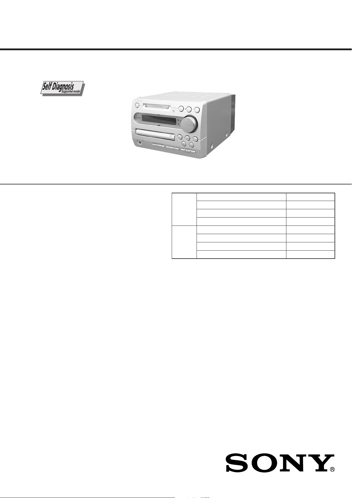
HCD-F3MD
SERVICE MANUAL
HCD-F3MD is the Amplifier, CD player, MD
Deck and Tuner section in CMT-F3MD.
US and foreign patents licensed from Dolby
Laboratories.
CD
Section
MD
Section
E Model
Model Name Using Similar Mechanism HCD-MD373
CD Mechanism Type CDM55A-5SBD32
Base Unit Name BU-5SBD32
Optical Pick-up Name KSS-213BH/Z-NP
Model Name Using Similar Mechanism HCD-MD373
MD Mechanism Type MDM-5GA
Base Unit Name MBU-5A
Optical Pick-up Name KMS-260B/S1NP
Amplifier section
DIN power output (Rated):20 + 20 watts (6 ohms at 1 kHz,
Continuous RMS power output (Reference):
Peak Music Power Output:400 watts
Inputs
TAPE IN (phono jacks): voltage 250 mV, impedance
Outputs
TAPE OUT (phono jacks):voltage 250 mV, impedance
PHONES (stereo minijack):
SPEAKER: accepts impedance of 6 to 16
CD player section
System Compact disc and digital audio
Laser Semiconductor laser (λ=780 nm)
DIN, 240 V)
18 + 18 watts (6 ohms at 1 kHz,
DIN, 220 V)
25 + 25 watts (6 ohms at 1 kHz,
10% THD, 240 V)
23 + 23 watts (6 ohms at 1 kHz,
10% THD, 220 V)
47 kilohms
1 kilohm
accepts headphones of 8 ohms or
more.
ohms.
system
Emission duration: continuous
SPECIFICATIONS
Laser output Max. 44.6 µW*
Frequency response 2 Hz – 20 kHz
MD deck section
System MiniDisc digital audio system
Laser Semiconductor laser (λ=780 nm)
Laser output Max. 44.6 µW*
Sampling frequency 44.1 kHz
Frequency response 5 Hz –
T uner section
FM stereo, FM/AM superheterodyne tuner
FM tuner section
Tuning range 87.5 – 108.0 MHz
Aerial FM lead aerial
Aerial terminals 75 ohms unbalanced
Intermediate frequency 10.7 MHz
*This output is the value measured
at a distance of 200 mm from the
objective lens surface on the
Optical Pick-up Block with a
7 mm aperture.
Emission duration: continuous
*This output is the value measured
at a distance of 200 mm from the
objective lens surface on the
Optical Pick-up Block with a
7 mm aperture.
20 kHz
(50 kHz step)
COMPACT DISC DECK RECEIVER
AM tuner section
Tuning range 531 – 1,602 kHz
Aerial AM loop aerial
Intermediate frequency 450 kHz
General
Power requirements 110 – 120 V or 220 – 240 V
Power consumption 70 watts during normal operation
Dimensions (w/h/d) incl. projecting parts and controls
Mass
Design and specifications are subject to change
without notice.
(with the interval set at 9 kHz)
530 – 1,710 kHz
(with the interval set at 10 kHz)
External aerial terminals
AC, 50/60 Hz
Approx. 3 watts in standby mode
(clock displayed)
Approx. 1 watt in standby mode
(clock not displayed)
Approx. 215 × 150 × 335 mm
Approx. 4.9 kg
SELF-DIAGNOSIS FUNCTION
The self-diagnosis function consists of error codes for customers, which are displayed automatically when errors occur, and error codes,
which show the error history in the test mode during servicing. For details on how to view error codes for the customer, refer to the
following box in the instruction manual. For details on how to check error codes during servicing, refer to the following “Procedure for
using the Self-Diagnosis Function (Error History Display Mode)”.
C13/REC Error
Self-diagnosis Display
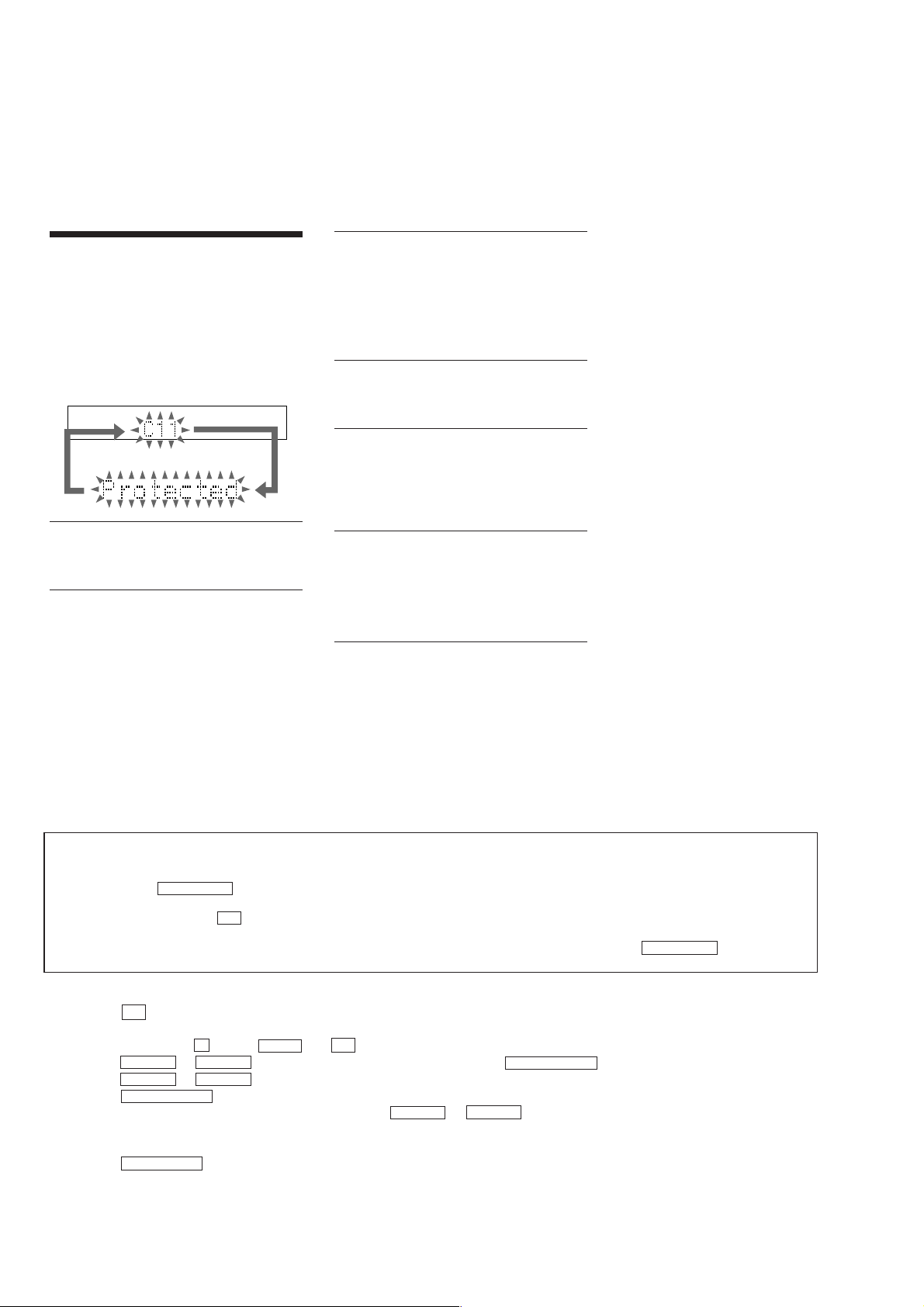
This system has a Self-diagnosis display function
to let you know if there is a system malfunction.
The display shows a code made up of three letters
and a message alternately to show you the
problem. To solve the problem refer to the
following list. If any problem persists, consult
your nearest Sony dealer.
C11/Protected
The MD is protected against erasure.
cRemove the MD and slide the tab to close the
slot (see page 24).
C12/Cannot Copy
You tried to record a CD or MD with a format
that the system does not support, such as a CDROM.
cRemove the disc and turn off the system once,
then turn it on again.
Recording could not be performed properly.
cMove the system to a stable place, and start
recording over from the beginning.
The MD is dirty or scratched, or the MD does
not meet the standards.
cReplace the MD and start recording over from
the beginning.
C13/Read Error
The MD deck cannot read the disc information
properly.
cRemove the MD once, then insert it again.
C14/Toc Error
The MD deck cannot read the disc information
properly.
cReplace the MD.
cErase all the recorded contents of the MD
using the All Erase function on page 38.
C41/Cannot Copy
The sound source is a copy of a commercially
available music software, or you tried to record
a CD-R (Recordable CD).
cThe Serial Copy Management System
prevents making a digital copy (see page 53).
You cannot record a CD-R.
PROCEDURE FOR USING THE SELF-DIAGNOSIS FUNCTION (ERROR HISTORY DISPLAY MODE)
Note 1: About “R”
As this unit has only a few buttons, some operations require the use of remote commander (RM-SF3MD/provided with unit: 1-476-068-11)
buttons. These operations are indicated as “R” in this manual.
Example: MENU/NO “R” ...Press the [MENU/NO] button of the remote commander.
Note 2: Incor rect operations may be performed if the MD test mode is not entered properly.
In this case, press the I/1 button to turn the power off, and retry to enter the MD test mode.
Note 3: Perform the self-diagnosis function in the “error history display mode” in the MD test mode. The following describes the least required
procedure. Be careful not to enter other modes by mistake. If you set other modes accidentally, press the MENU/NO “R” button to exit the
mode.
Procedure:
1. Press the I/1 button to turn the power on.
2. Press the [FUNCTION] button to set the MD function.
3. Press three buttons of s (MD) , zREC and I/1 simultaneously to enter the MD test mode and display “[Check]”.
4. Press the l m or M L button to display “[Service]”, and press the ENTER/YES “R” button.
5. Press the l m or M L button to display “ERR DP MODE”.
6. Press the ENTER/YES “R” button to enter the error history mode and display “total rec”.
7. Select the contents to be displayed or executed using the l m or M L button.
8. Press the [CD-MD SYNC] button will display or execute the contents selected.
9. Press the [CD-MD SYNC] button another time returns to step 7.
10. Press the MENU/NO “R” button displays “ERR DP MODE” and release the error history mode.
11. To release the MD test mode, press the [REPEAT] button to display “Initialize” and release the MD test mode.
2
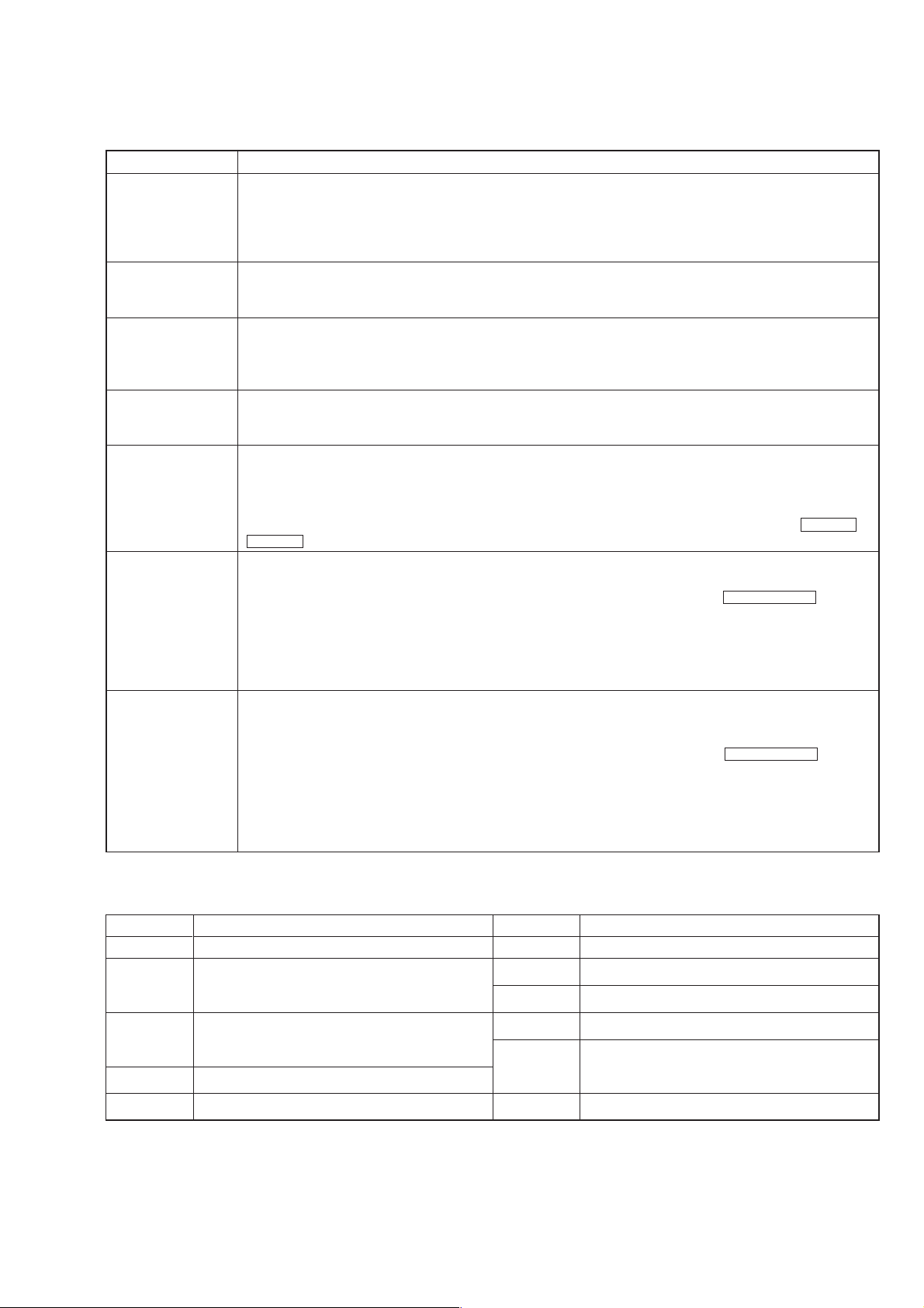
ITEMS OF ERROR HISTORY MODE ITEMS AND CONTENTS
Selecting the Test Mode
Display
total rec Displays the recording time.
Displayed as “rssssssh”.
The displayed time is the total time the laser is set to the high power state.
This is about 1/4 of the actual recording time.
The time is displayed in decimal digits from 0h to 65535h.
total play Displays the play time.
Displayed as “pssssssh”. The time displayed is the total actual play time. Pauses are not counted.
The time is displayed in decimal digits from 0h to 65535h.
retry err Displays the total number of retries during recording and number of retry errors during play.
Displayed as “rss pss”.
“r” indicates the retries during recording while “p” indicates the retry errors during play.
The number of retries and retry errors are displayed in hexadecimal digits from 00 to FF.
total err Displays the total number of errors.
Displayed as “total ss”.
The number of errors is displayed in hexadecimal digits from 00 to FF.
err history Displays the 10 latest errors.
Displayed as “0s E@@”.
s indicates the history number. The smaller the number, the more recent is the error. (00 is the latest).
@@ indicates the error code.
Refer to the following table for the details. The error history can be switched by pressing the
M L button.
er refresh Mode which erases the “retry err”, “total err”, and “err history” histories.
When returning the unit to the customer after completing repairs, perform this to erase the past error history.
After pressing the
erase the history.
“Complete!” will be displayed momentarily.
Be sure to check the following when this mode has been executed.
• The data has been erased.
• The mechanism operates normally when recording and play are performed.
tm refresh Mode which erases the “total rec” and “total play” histories.
These histories serve as approximate indications of when to replace the optical pick-up.
If the optical pickup has been replaced, perform this operation and erase the history.
After pressing the
erase the history.
“Complete!” will be displayed momentarily.
Be sure to check the following when this mode has been executed.
• The data has been erased.
• The mechanism operates normally when recording and play are performed.
[CD-MD SYNC] button and “er refresh?” is displayed, press the ENTER/YES “R” button to
[CD-MD SYNC] button and “tm refresh?” is displayed, press the ENTER/YES “R” button to
Details of History
l m or
Table of Error Codes
Error Code Error Code Details of Error
E00 No error
E01 Disc error. PTOC cannot be read
(DISC ejected)
E02 Disc error. UTOC error
(DISC not ejected)
E03 Loading error
E04 Address cannot be read (Servo has deviated)
Details of Error
E05 FOK has deviated
E06 Cannot focus (Servo has deviated)
E07 Recording retry
E08 Recording retry error
E09 Playback retry error
(Access error)
E0A Playback retry error (C2 error)
3
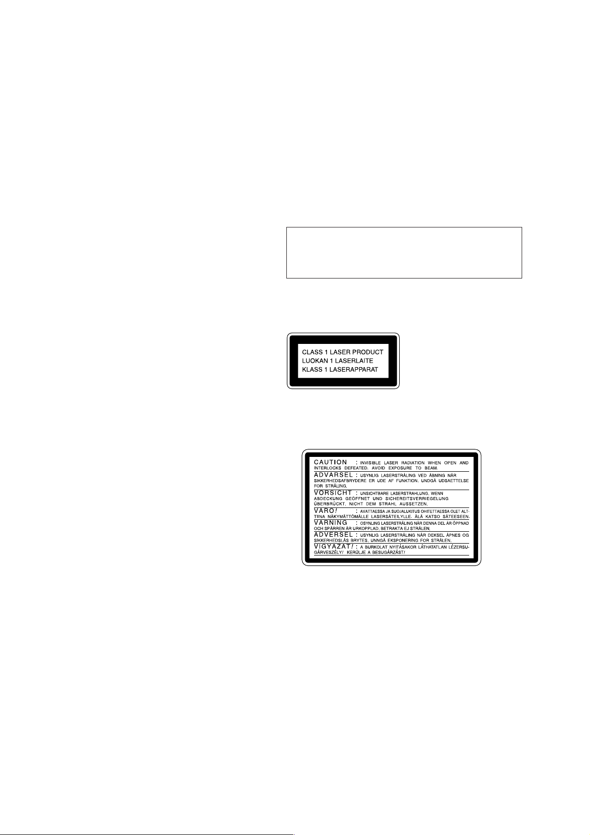
TABLE OF CONTENTS
SELF-DIAGNOSIS FUNCTION..................................... 2
1. SERVICING NOTES ............................................... 5
2. GENERAL ................................................................... 16
3. DISASSEMBLY ......................................................... 18
4. TEST MODE ............................................................... 26
5. ELECTRICAL ADJUSTMENTS
MD Section ..................................................................... 30
CD Section ...................................................................... 38
6. DIAGRAMS
6-1. Block Diagram – CD SERVO Section – ....................... 39
6-2. Block Diagram – MD SERVO Section (1/2) – ............. 40
6-3. Block Diagram – MD SERVO Section (2/2) – ............. 41
6-4. Block Diagram – MAIN Section –................................ 42
6-5. Note for Printed Wiring Boards and
Schematic Diagrams ....................................................... 43
6-6. Printed Wiring Board – BD (CD) Board – .................... 44
6-7. Schematic Diagram – BD (CD) Board –....................... 45
6-8. Schematic Diagram – BD (MD) Board (1/2) –............. 46
6-9. Schematic Diagram – BD (MD) Board (2/2) –............. 47
6-10. Printed Wiring Board – BD (MD) Board – ................... 48
6-11. Schematic Diagram – BD SW (MD) Board – ............... 49
6-12. Printed Wiring Board – BD SW (MD) Board – ............ 49
6-13. Schematic Diagram – LOADING (CD) Board – .......... 49
6-14. Printed Wiring Board – LOADING (CD) Board – ....... 49
6-15. Printed Wiring Board – MD DIGITAL Board – ........... 50
6-16. Schematic Diagram – MD DIGITAL Board – .............. 51
6-17. Printed Wiring Board – MAIN Board – ........................ 52
6-18. Schematic Diagram – MAIN Board (1/3) – .................. 53
6-19. Schematic Diagram – MAIN Board (2/3) – .................. 54
6-20. Schematic Diagram – MAIN Board (3/3) – .................. 55
6-21. Printed Wiring Boards – AMP/SP Boards –.................. 56
6-22. Schematic Diagram – AMP/SP Boards – ...................... 57
6-23. Printed Wiring Board – PANEL Board – ...................... 58
6-24. Schematic Diagram – PANEL Board – ........................ 59
6-25. Printed Wiring Board – POWER Board –..................... 60
6-26. Schematic Diagram – POWER Board – ........................ 61
6-27. IC Pin Function Description ........................................... 70
Notes on chip component replacement
• Never reuse a disconnected chip component.
• Notice that the minus side of a tantalum capacitor may be dam-
aged by heat.
Flexible Circuit Board Repairing
• Keep the temperature of the soldering iron around 270 ˚C during repairing.
• Do not touch the soldering iron on the same conductor of the
circuit board (within 3 times).
• Be careful not to apply force on the conductor when soldering
or unsoldering.
CAUTION
Use of controls or adjustments or performance of procedures
other than those specified herein may result in hazardous radiation exposure.
This appliance is classified as a CLASS 1 LASER product.
The CLASS 1 LASER PRODUCT MARKING is located on
the rear exterior.
Laser component in this product is capable of emitting radiation
exceeding the limit for Class 1.
The following caution label is located inside the unit.
7. EXPLODED VIEWS................................................ 80
8. ELECTRICAL PARTS LIST ............................... 86
4
SAFETY-RELATED COMPONENT WARNING!!
COMPONENTS IDENTIFIED BY MARK 0 OR DOTTED
LINE WITH MARK 0 ON THE SCHEMATIC DIAGRAMS
AND IN THE PARTS LIST ARE CRITICAL TO SAFE
OPERATION. REPLACE THESE COMPONENTS WITH
SONY PARTS WHOSE PART NUMBERS APPEAR AS
SHOWN IN THIS MANUAL OR IN SUPPLEMENTS PUBLISHED BY SONY.
SECTION 1
SERVICING NOTES
NOTES ON HANDLING THE OPTICAL PICK-UP
BLOCK OR BASE UNIT
The laser diode in the optical pick-up block may suffer electrostatic break-down because of the potential difference generated
by the charged electrostatic load, etc. on clothing and the human
body.
During repair, pay attention to electrostatic break-down and also
use the procedure in the printed matter which is included in the
repair parts.
The flexible board is easily damaged and should be handled with
care.
For CD
NOTES ON LASER DIODE EMISSION CHECK
The laser beam on this model is concentrated so as to be focused
on the disc reflective surface by the objective lens in the optical
pick-up block. Therefore, when checking the laser diode emission, observe from more than 30 cm away from the objecti ve lens.
LASER DIODE AND FOCUS SEARCH OPERATION
CHECK
Carry out the “S curve check” in “CD section adjustment” and
check that the S curve waveforms is output three times.
For MD
NOTES ON LASER DIODE EMISSION CHECK
Never look into the laser diode emission from right above when
checking it for adjustment. It is feared that you will lose your sight.
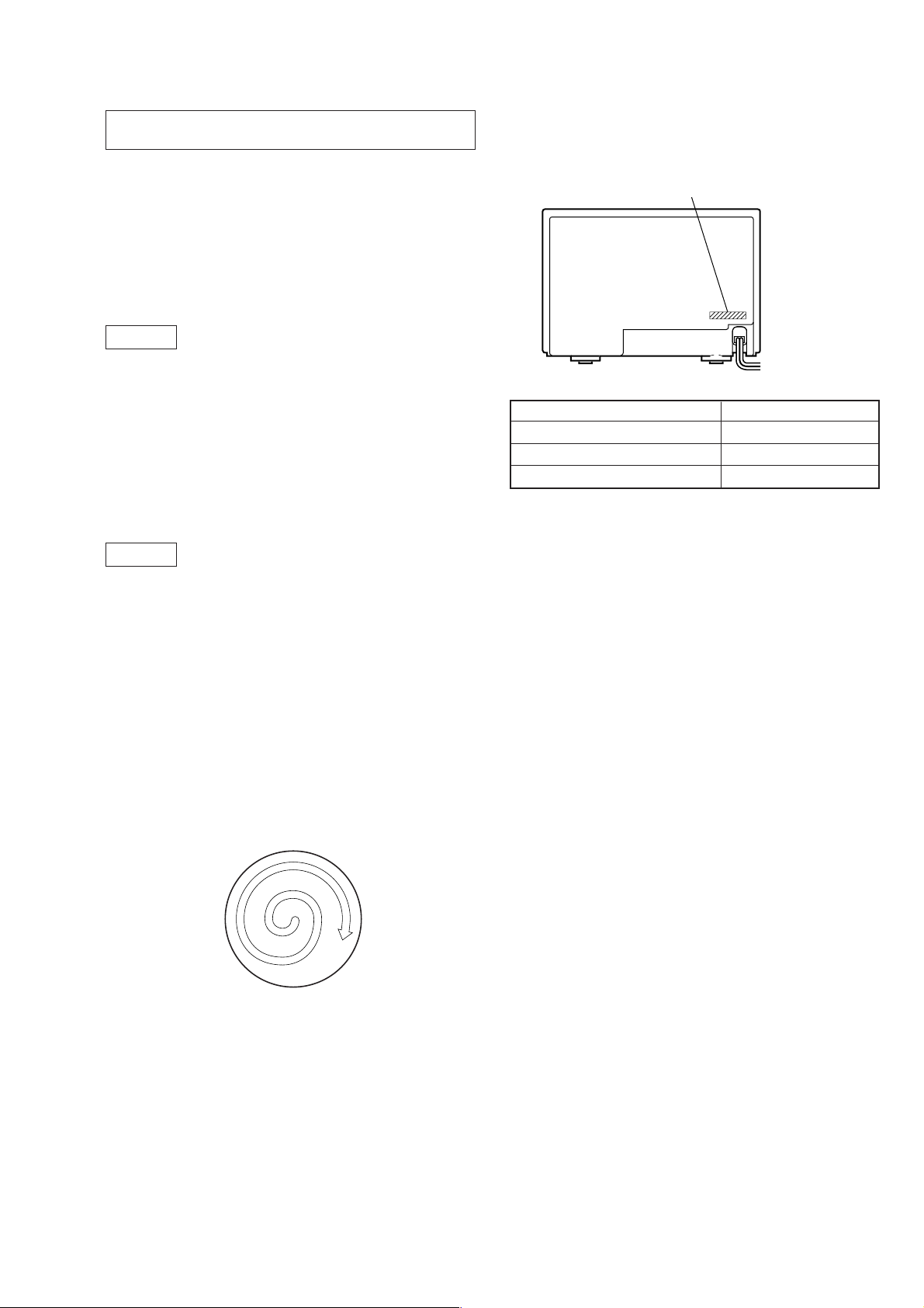
MODEL IDENTIFICATION
— Back panel —
PART No.
Model Part No.
Hong Kong model 4-229-548-1[]
Korean model 4-232-128-0
Taiwan model 4-232-129-0
[]
[]
CLEANING OBJECTIVE LENS OF OPTICAL PICK-UP
• In cleaning the objective lens of optical pick-up, be sure the
following below.
1. In cleaning the lens, do not apply an excessive force.
As the optical pick-up is vulnerable, application of excessive
force could damage the lens holder.
2. In cleaning, do not use a cleaner other than exclusive cleaning
liquid (KK-91 or isopropyl alcohol).
3. Wipe the objective lens spirally from center toward outside.
(See Figure A)
(Figure A)
4. Eject the disk, if loaded.
5. Disconnect the power cord from the socket to shut off the po wer
supply.
6. When cleaning the objective lens of optical pick-up in CD,
refer to “HOLDER (BU) ASS’Y” on page 24 for removing
HOLDER (BU) ASS’Y.
5
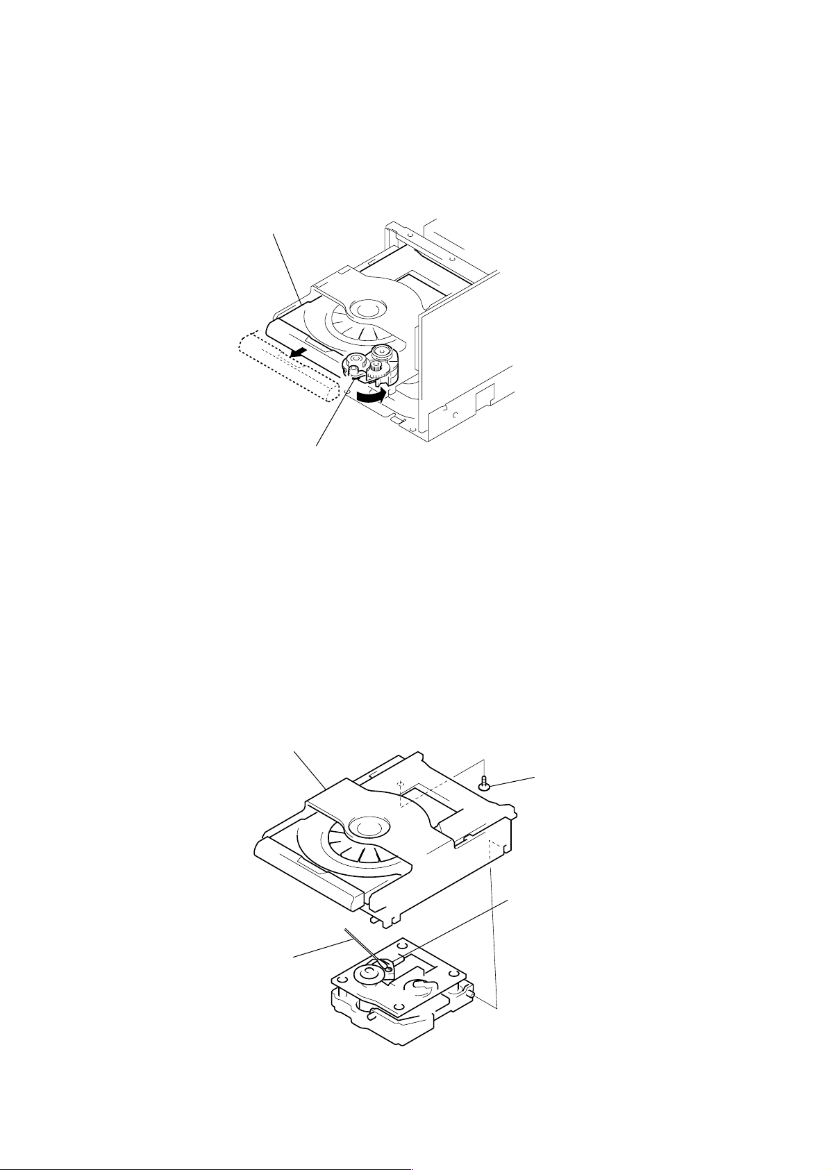
DRAWING OUT THE TRAY WHEN THE POWER IS OFF
tray (CDM)
A
Move the cam block in the direction
of arrow
A
with a finger.
CLEANING THE OPTICAL PICK-UP (CD PLAYER)
CD mechanism deck
Clean the lens block
with a cotton bud.
floating screw
(PTPWH M2.6)
optical pick-up block
6
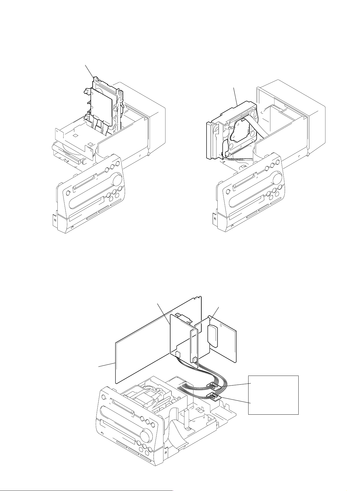
SERVICE POSITION OF THE MD MECHANISM
DECK
MD mechanism deck
SERVICE POSITION OF THE CD MECHANISM
DECK
CD mechanism deck
SERVICE POSITION OF THE POWER BOARD
POWER board
CN993
MAIN board
AMP board
CN802
Extension cable (4P)
(J-2501-042-A)
Extension cable (3P)
(J-2501-045-A)
7

MC COLD RESET
• The cold reset clears all data including preset data stored in the RAM to initial conditions. Execute this mode when returning the set to
the customer.
Procedure:
1. Press the I/1 button to turn the power on.
2. While pressing the [PLAY MODE/TUNING MODE] and s (CD) buttons, press the I/1 button.
3. The set is reset, and displays “COLD RESET”, then becomes standby status.
MC HOT RESET
• This mode resets the set with the preset data kept stored in the memory . The hot reset mode function is same as if the po wer cord is plugged
in and out.
Procedure:
1. Press the I/1 button to turn the power on.
2. While pressing the [PLAY MODE/TUNING MODE] and HS (CD) buttons, press the I/1 button.
3. The set is reset, and becomes standby state.
LED/FLUORESCENT INDICATOR TUBE AND KEY TEST
Procedure:
1. Press the I/1 button to turn the power on.
2. While pressing the [PLAY MODE/TUNING MODE] and A (CD) buttons, press the I/1 button.
3. LEDs and fluorescent indicator tube are all turned on.
4. Press the HS (MD) button to enter the key test mode, and display “Key0 Vol0”.
5. Each time a button is pressed, “Key” value increases. However, once a button is pressed, it is no longer taken into account.
“Vol” value increases like 0, 1, 2 ... if turn the [VOLUME] knob clockwise, or it decreases like 9, 8, 7 ... if turn the [VOLUME] knob
counterclockwise.
6. To release from this mode, press three buttons in the same manner as step 2, or disconnect the power cord.
Note: l m and M L buttons are no longer taken into account, if it pressed within for a second.
CHANGE-OVER THE AM TUNING INTERVAL
• The AM tuning interval can be changed over 9 kHz or 10 kHz.
Procedure:
1. Press the I/1 button to turn the power on.
2. Press the
3. Press the I/1 button to turn the power off.
4. When the power off, press the I/1 button while pressing the [PLAY MODE/TUNING MODE] button, and the display of fluorescent
indicator tube changes to “AM 9k STEP” or “AM 10k STEP”, and thus the tuning interval is changed over.
[FUNCTION] button to set the TUNER function, and press the [TUNER/BAND] button to select the band “AM”.
8
MD SECTION
r
3
5
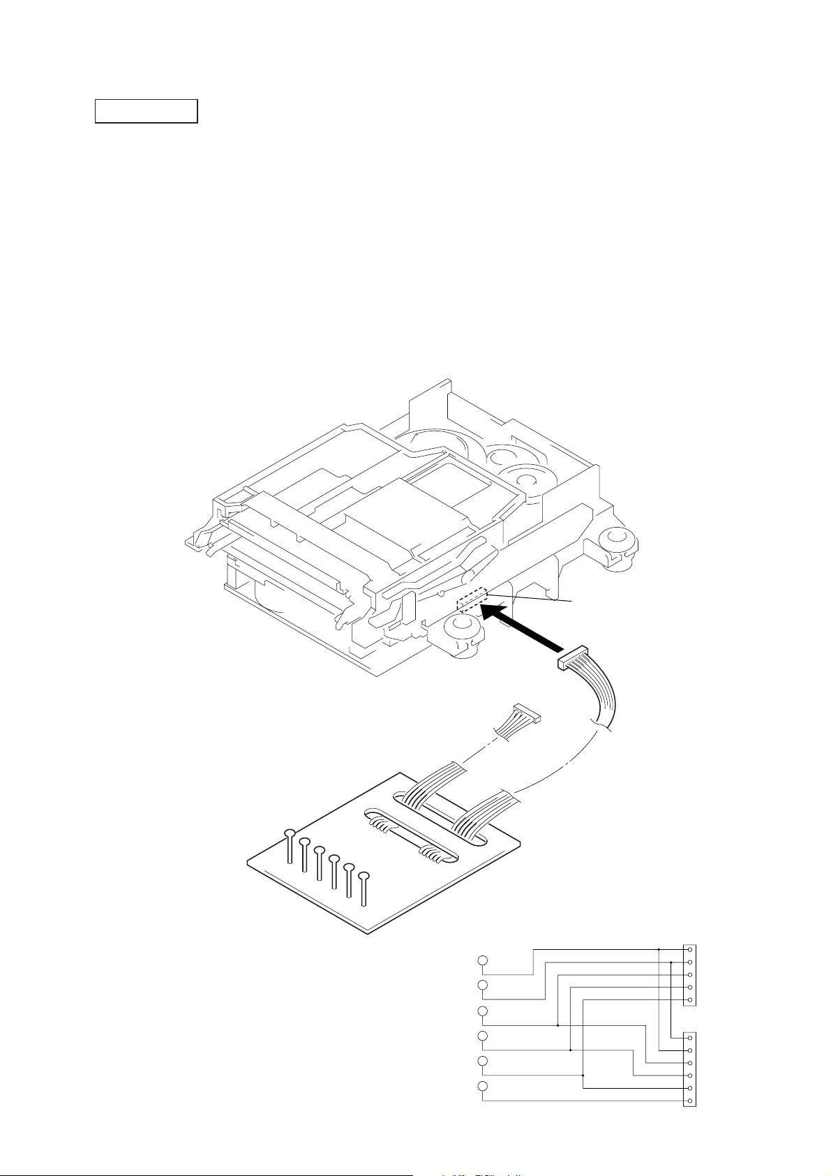
JIG FOR CHECKING BD (MD) BOARD WAVEFORM
The special jig (J-2501-149-A) is useful for checking the waveform of the BD (MD) board. T he names of terminals and the checking items
to be performed are shown as follows.
GND: Ground
I+3V : For measuring IOP (Check the deterioration of the optical pick-up laser)
IOP : For measuring IOP (Check the deterioration of the optical pick-up laser)
TEO : Tracking error signal (Traverse adjustment)
VC : Reference level for checking the signal
RF : RF signal (Check jitter)
Mechanism deck
RF
VC
TEO
IOP
I+3V
GND
RF
VC
TEO
5P connector
CN110
6P connecto
1
RF
VC
for
TEO
MDM-
IOP
I+3V
5
1
IOP
I+3V
GND
VC
RF
for
TEO
IOP
MDM-
I+3V
6
GND
9

Note : About “R”
As this unit has only a few buttons, some operations require the use of remote commander (RM-SF3MD/provided with unit: 1-476-068-11)
buttons. These operations are indicated as “R” in this manual.
Example: MENU/NO “R” ...Press the [MENU/NO] button of the remote commander.
IOP DATA RECORDING AND DISPLAY WHEN OPTICAL PICK-UP AND NON-VOLATILE MEMORY (IC171 ON THE BD
(MD) BOARD) ARE REPLACED
The IOP value labeled on the optical pick-up can be recorded in the non-volatile memory. By recording the value, it will eliminate the need
to look at the value on the label of the optical pick-up. When replacing the optical pick-up or non-v olatile memory (IC171 on the BD (MD)
board), record the IOP value on the optical pick-up according to the following procedure.
Record Procedure:
1. Press the I/1 button to turn the power on.
2. Press the [FUNCTION] button to set the MD function.
3. While pressing the s (MD) and zREC buttons, press the I/1 button to enter the MD test mode and display “[Check]”.
4. Press the l m or M L button to display “[Service]”, and press the ENTER/YES “R” button.
5. Press the l m or M L button to display “Iop Write”, and press the ENTER/YES “R” button.
6. The display becomes “Ref=@@@.@” (@ is an arbitrary number) and the numbers which can be changed will blink.
7. Input the IOP value written on the optical pick-up.
To select the number : Press the l m or M L button.
To select the digit : Press the [SYNC REC] button.
8. When the ENTER/YES “R” button is pressed, the display becomes “Measu=@@@.@” (@ is an arbitrary number).
9. As the adjustment results are recorded for the step7 value. Leave it as it is and press the ENTER/YES “R” button.
10. “Complete!” will be displayed momentarily. The value will be recorded in the non-volatile memory and the display will become “Iop
Write”.
11. Press the [REPEAT] button to complete. “Standby” will be displayed.
Display Procedure:
1. Press the I/1 button to turn the power on.
2. Press the [FUNCTION] button to set the MD function.
3. While pressing the s (MD) and zREC buttons, press the I/1 button to enter the MD test mode and display “[Check]”.
4. Press the l m or M L button to display “[Service]”, and press the ENTER/YES “R” button.
5. Press the l m or M L button to display “Iop Read”, and press the ENTER/YES “R” button.
6. “@@.@/##.#” is displayed and the recorded contents are displayed.
@@.@: indicates the Iop value labeled on the pick-up.
##.# : indicates the Iop value after adjustment
7. To release, press the [CD-MD SYNC] button or MENU/NO “R” button to display “Iop Read”. Then press the [REPEAT] button to
display “Standby”.
10

CHECKS PRIOR TO PARTS REPLACEMENT AND ADJUSTMENTS
Before performing repairs, perform the following checks to determine the faulty locations up to a certain extent.
Details of the procedures are described in “5 Electrical Adjustments”.
Laser power check
(5-6-2 : See page 32)
Traverse check
(5-6-3 : See page 32)
Focus bias check
(5-6-4 : See page 33)
C PLAY check
(5-6-5 : See page 33)
Self-recording/playback
check
(5-6-6 : See page 33)
Temperature
compensation
offset check
(5-6-1 : See page 32)
Criteria for Determination
(Unsatisfactory if specified value is not satisfied)
• 0.9 mW power
Specified value : 0.84 to 0.92 mW
• 7.0 mW power
Specified value : 6.8 to 7.2 mW
lop (at 7mW)
• Labeled on the optical pickup
Iop value ± 10mA
• Traverse waveform
Specified value : Below 10% offset
• Error rate check
Specified value : For points A, B
C1 error : About 200
AD error : Below 2
For point C
C1 error : Below 50
AD error : Below 2
• Error rate check
Specified value:
a. When using test disc (MDW-74/AU-1)
C1 error : Below 80
AD error : Below 2
b. When using check disc (TDYS-1)
C1 error : Below 50
• CPLAY error rate check
Specified value:
C1 error : Below 80
AD error : Below 2
• Unsatisfactory if displayed as T=@@ (##) [NG”
NG
(@@, ## are both arbitrary numbers)
• Clean the optical pick-up
• Adjust again
• Replace the optical pick-up
• Replace the optical pick-up
• Replace the optical pick-up
• Replace the optical pick-up
• Replace the optical pick-up
If always unsatisfactory:
• Replace the overwrite head
• Check for disconnection of the circuits around the
overwrite head
If occasionally unsatisfactory:
• Check if the overwrite head is distorted
• Check the mechanism around the sled
• Check for disconnection of the circuits around
D101 (BD (MD) board)
• Check the signals around IC101, IC121, CN102,
CN103 (BD (MD) board)
Measure if unsatisfactory:
Note:
The criteria for determination above is intended merely to determine if satisfactory or not, and does not serve as the specified value for adjustments.
When performing adjustments, use the specified values for adjustments.
11
RETRY CAUSE DISPLAY MODE
• In this test mode, the causes for retry of the unit during recording can be displayed on the fluorescent indicator tube. During playback,
the “track mode” for obtaining track information will be set.
This is useful for locating the faulty part of the unit.
• The following will be displayed :
During recording and stop: Retry cause, number of retries, and number of retry errors.
During playback : Information such as type of disc played, part played, copyright.
These are displayed in hexadecimal.
Procedure:
1. Load a recordable disc whose contents can be erased into the unit.
2. Press the MENU/NO “R” button. When “Edit Menu” is displayed on the fluorescent indicator tube, press the l m or M L
button to display “All Erase?”.
3. Press the ENTER/YES “R” button.
4. When “All Erase??” is displayed on the fluorescent indicator tube, the music calendar number blinks.
5. Press the ENTER/YES “R” button to display “Complete!!”, and press the s (MD) button immediately. Wait for about 10 seconds
while pressing the button.
6. When the “TOC” displayed on the fluorescent display tube goes off, release the s (MD) button.
7. Press the zREC button to start recording. Then press the HS (MD) button and start recording. If recording cannot be performed,
press the [FUNCTION] button and set a different function.
8. To check the “track mode”, press the HS (MD) button to start play.
9. To release the test mode, press the I/1 button, and turn the power off. When “TOC” disappears, disconnect the power plug from the
outlet. If the test mode cannot be released, refer to “MC COLD RESET” on page 8).
Fig. 1 Reading the Test Mode Display
(During recording and stop)
RTs@@c##e
Fluorescent indicator tube display
@@ : Cause of retry
## : Number of retries
: Number of retry errors
**
Reading the Retry Cause Display
Higher Bits Lower Bits
Hexadecimal
Bit
Binary
84218421
b7 b6 b5 b4 b3 b2 b1 b0
00000001
00000010
00000100
00001000
00010000
00100000
01000000
10000000
**
Hexa-
decimal
01
02
04
08
10
20
40
80
Cause of Retry
shock
ader5
Discontinuous address
DIN unlock
FCS incorrect
IVR rec error
CLV unlock
Access fault
Fig. 2 Reading the Test Mode Display
(During playback)
@@ ###
Fluorescent indicator tube display
@@ : Parts No. (name of area named on TOC)
## : Cluster
: Sector
**
$$ : Track mode (Track information such as copy-
right information of each part)
When track jump (shock) is detected
When ADER was counted more than five times
continuously
When ADIP address is not continuous
When DIN unlock is detected
When not in focus
When ABCD signal le v el e xceeds the specified range
When CLV is unlocked
When access operation is not performed normally
Address
Occurring conditions
**
$$
Reading the Display:
Convert the hexadecimal display into binary display. If more than two causes, they will be added.
Example
When 42 is displayed:
Higher bit: 4 = 0100 t b6
Lower bit : 2 = 0010 t b1
In this case, the retry cause is combined of “CLV unlock” and “ader5”.
When A2 is displayed:
Higher bit: A = 1010 t b7+b5
Lower bit : 2 = 0010 t b1
The retry cause in this case is combined of “access fault”, “IVR rec error”, and “ader5”.
12
Reading the Retry Cause Display
Higher Bits
Hexadecimal
Bit
Binary
Reading the Display:
Convert the hexadecimal display into binary display. If more than two causes, they will be added.
Example When 84 is displayed:
Higher bit: 8 = 1000 t b7
Lower bit : 4 = 0100 t b2
In this case, as b2 and b7 are 1 and others are 0, it can be determined that the retry cause is combined of “emphasis OFF”, “monaural”,
“original”, “copyright exists”, and “write allowed”.
Example When 07 is displayed:
Higher bit: 0 = 0000 t All 0
Lower bit : 7 = 0111 t b0+b1+b2
In this case, as b0, b1, and b2 are 1 and others are 0, it can be determined that the retry cause is combined of “emphasis ON”, “stereo”,
“original”, “copyright exists”, and “write prohibited”.
84218421
b7 b6 b5 b4 b3 b2 b1 b0
00000001
00000010
00000100
00001000
00010000
00100000
01000000
10000000
Lower Bits
Hexa-
decimal
01
02
04
08
10
20
40
80
When 0
Emphasis OFF
Monaural
This is 2-bit display. Normally 01.
01:Normal audio. Others:Invalid
Audio (Normal)
Original
Copyright
Write prohibited
Details
When 1
Emphasis ON
Stereo
Invalid
Digital copy
No copyright
Write allowed
Hexadecimal t Binary Conversion Table
Hexadecimal Binary Hexadecimal Binary
0 0000 8 1000
1 0001 9 1001
2 0010 A 1010
3 0011 B 1011
4 0100 C 1100
5 0101 D 1101
6 0110 E 1110
7 0111 F 1111
13
CD SECTION
CD TEXT DISPLA Y
• This unit displays CD text.
Text is displayed for the first 50 tracks only and will not be displayed from the 51st track onwards. Do not suspect a fault in this case.
In some cases, some special characters will not be displayed and may be replaced by other characters. Do not suspect a fault in this case.
AGING MODE
• Mode for repeating operations of the CD player automatically.
When errors occur:
Aging stops and a message indicating that an error has occurred such as “CD MEC ERR” is displayed.
(For details of errors, refer to “Error History Display Mode”)
When no errors occur:
Aging is repeatedly performed.
Procedure:
1. Load any CD disc.
2. Press the [FUNCTION] button to set the CD function.
3. While pressing the [PLAY MODE/TUNING MODE] and HS (MD) buttons, press the I/ 1 button.
4. “AGING” is displayed on the fluorescent display tube briefly.
5. When the aging mode is set, it starts aging automatically.
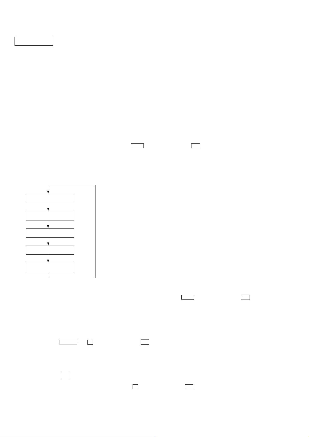
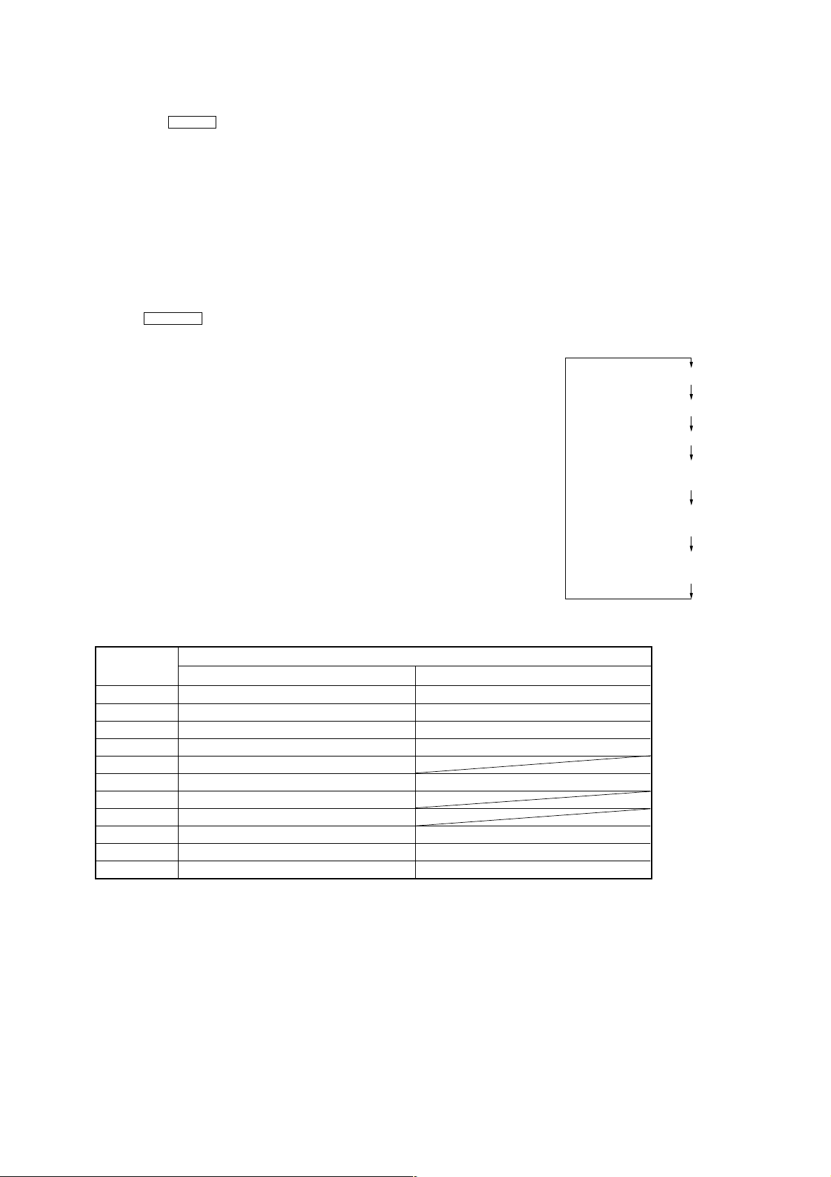
6. Operations are performed in the following sequence during aging.
Aging mode sequence:
TOC read
Playback track 1
Playback last track
CD disc tray open
CD disc tray open
7. To release from this mode, while pressing the
(Hot reset is executed)
Error History Display Mode
Mode for checking the history of errors which have occurred in the CD player.
Execute this mode after ending the aging mode.
Procedure:
1. Press the [FUNCTION] button to set the CD function.
2. While pressing the M L and s (MD) buttons, press the I/1 button.
3. “EMC@@EDC**” is displayed.
@@ : Number of mechanism errors (Past 3 errors)
: Number of errors (NO DISC ERROR) which occurred after chucking (Past 3 errors)
**
4. To check the history of mechanism errors, press the [PLAY MODE/TUNING MODE] button, and to check BD errors, press the
[PLAY MODE/TUNING MODE] and HS (CD) buttons, press the I/1 button.
[REPEAT] button, and switch the display.
5. To release, press the I/1 button and turn the power off.
6. To erase the error history, perform COLD reset.
(While pressing the [PLAY MODE/TUNING MODE] and s (CD) buttons, press the I/1 button)
14

• Reading the Mechanism Error History Display
(To switch the history, press the [PLAY MODE/TUNING MODE] button)
Display
E@@M
@@ : Error number. 00 is the latest
*
# : Load in operations related
$ : Load out operations related
• Reading the BD Error History Display
(To switch the history, press the [REPEAT] button)
E@@D##$$%
@@ : Error number. 00 is the latest
## : Error details
$$ : Retry performed/not performed
% : State when determined as NO DISC
*
**#*$*
: Invalid
D : Operations stopped due to problems other than mechanism related during CLOSE
E : Operations stopped due to problems other than mechanism related during OPEN
C : Operations stopped due to problems other than mechanism related during chucking up
1 : Operations stopped during chucking up
2 : Operations stopped during chucking down
Display
*
01: Focus error
02: GFS error
03: Setup error
00: Determined as NO DISC without chucking retry
02: Determined as NO DISC after chucking retry
1 : When stopped
2 : During setup
3 : During TOC READ
4 : During access
5 : During playback
6 : During PAUSE
7 : During manual search (during playback)
8 : During manual search (during pause)
: Invalid
15
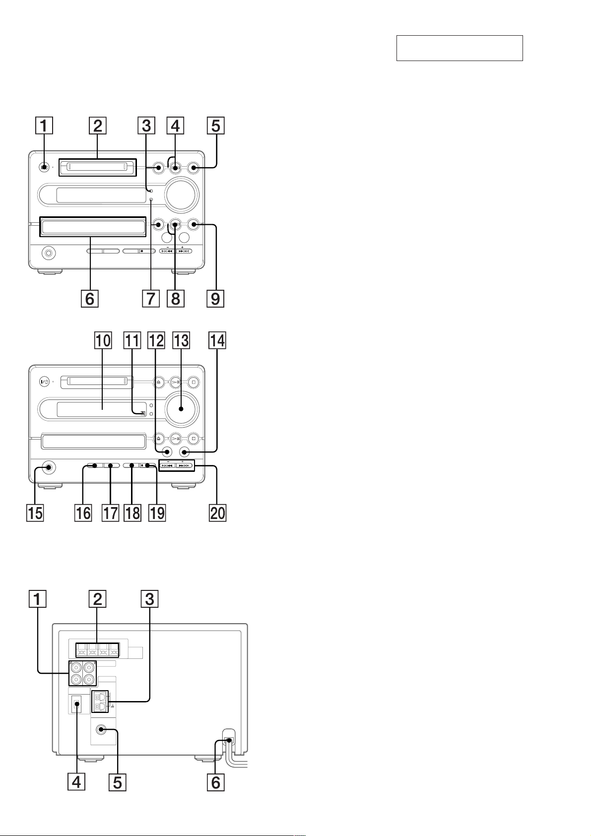
LOCATION OF CONTROLS
• Front View
SECTION 2
GENERAL
1 I/1 button and indicator
2 MD disc slot
3 MD A button and MD disc indicator
4 MD H S button and indicator
5 MD s button
6 CD disc tray
7 CD A button and CD disc indicator
8 CD H S button and indicator
9 CD s button
This section is extracted from
instruction manual.
• Rear View
0 Fluorescent indicator tube
qa Remote sensor
qs TUNER/BAND button
qd VOLUME knob
qf FUNCTION button
qg PHONES jack
qh PLAY MODE, TUNING MODE button
qj REPEAT, STEREO/MONO button
qk CD-MD SYNC button
ql zREC button and indicator
w; MD/CD l m/M L, TUNUNG +/– buttons
1 TAPE IN/OUT jacks
2 SPEAKER IMPEDANCE 6-16 Ω terminals
3 AM ANTENNA terminals
4 TAPE CONTROL jack
5 FM 75 Ω COAXIAL jack
6 AC power cord
16
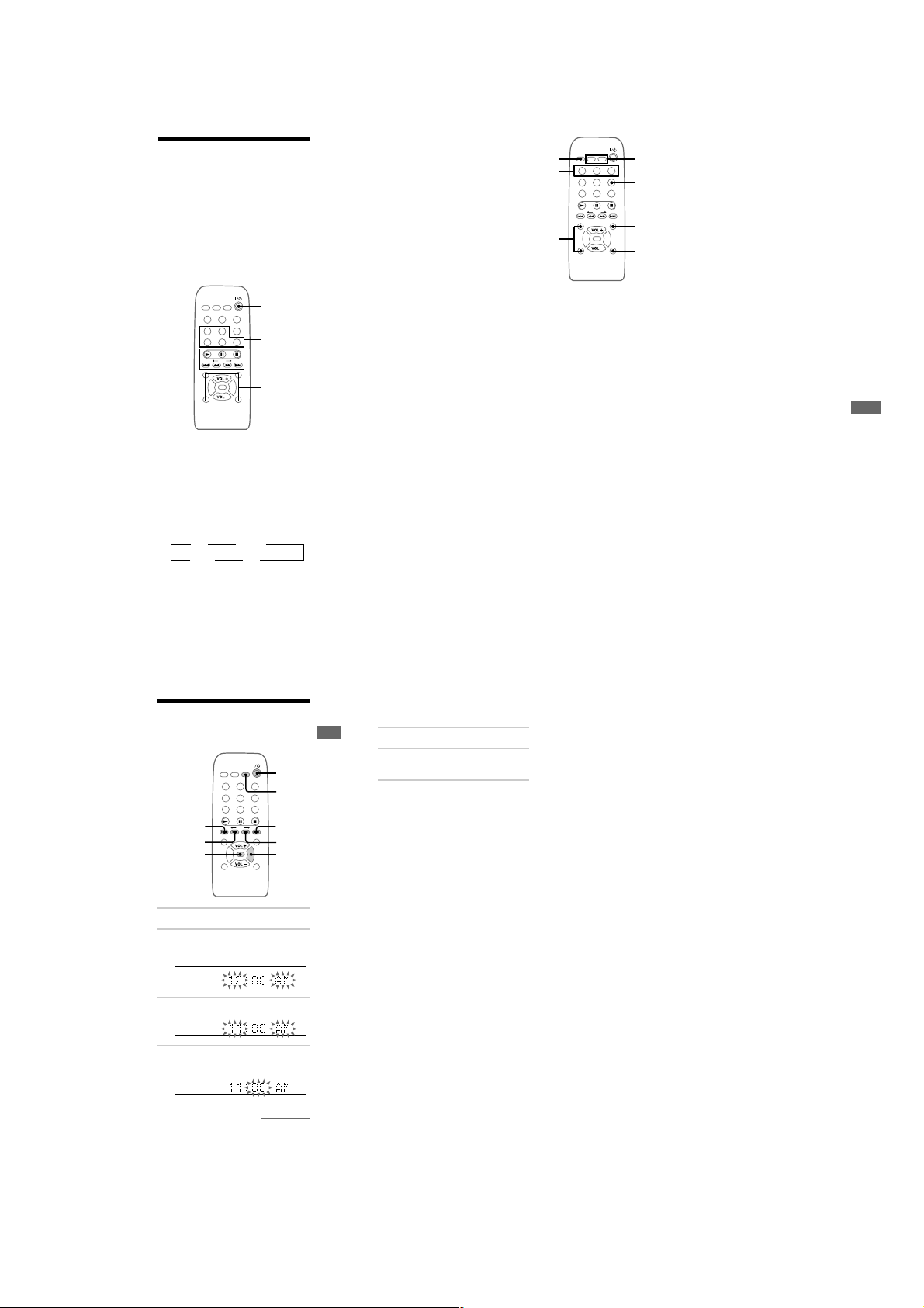
Parts descriptions for
the remote
You can use the supplied remote to control the
system.
Note
You cannot perform the following operations with the
remote;
— TUNING MODE setting for the tuner
— STEREO/MONO setting for the tuner
— Removing discs
— Recording on the MD
— One Touch Play
1
2
3
4
1 ?/1 (power) switch
2 The sound source buttons
MD button
CD button
TAPE button
FUNCTION button
Press to switch the sound source.
Each time you press this button, the sound source
changes as follows;
t
t
CD
TUNER
T
TAPE
TUNER/BAND button
Press to select the tuner for the sound source, or
to select the FM or AM band.
MD
T
3 N (play) button
X (pause) button
x (stop) button
CURSORT/t, m/M buttons
Press to label a CD, MD and preset station, or to
set the clock. (pages 5, 18, 35, 45)
./> (AMS: Automatic Music
Sensor) buttons
4 VOL +/– buttons
Press to adjust the volume.
MENU/NO button
Press to set Programme Play, or to label a CD,
MD and preset station.
ENTER/YES button
Press to set the clock, Programme Play and to
label a CD, MD and preset station, or to enter the
settings in “Edit Menu” or “Setup Menu”.
DISP button
Press to show the various information. (pages 17
and 23)
5
6
7
5 SLEEP button
Press to set Sleep Timer. (page 46)
6 PLAY MODE button
Press to select normal play, Shuffle Play or
Programme Play. (pages 15, 16, 21, 25)
REPEAT button
Press to play a track or all the tracks repeatedly
(pages 15 and 20).
MUSIC MENU button
Press to select the type of the preset equalizer.
(page 44)
7 NAME EDIT buttons
CHARACTER button
Press to display the text input screen and to select
the type of characters to be input. (pages 19, 35,
45)
SPACE button
Press to enter a space directly when labelling a
CD, MD and preset stion. (pages 19, 36, 46)
8 CLOCK/TIMER SELECT button
Press to check timer settings, or to set the timer
on/off. (pages 48 and 49)
CLOCK/TIMER
Press to set the clock and timer functions. (pages
5, 47, 48)
SET button
8
9
0
qa
9 DBFB button
Press to reinforce the bass sound. (page 44)
0 SCROLL button
Press to display the disc title or track title
scrolling. (pages 19, 23, 36)
qa CLEAR button
Press to cancel the selection. (pages 16, 18, 21,
35, 45)
Additional Information
60
Step 2: Setting the time
You must set the time beforehand to use the timer
functions.
3,5
CURSORT
DISP
1
Turn on the system.
2
Press CLOCK/TIMER SET.
The clock appears and the hour indication
flashes.
3
Press . or > to set the hour.
4
Press ENTER/YES or CURSORt .
The minute indication flashes.
1
2
3,5
4
4,6
Getting Started
Step 2: Setting the time
(continued)
5 Press . or > to set the minute.
6 Press ENTER/YES.
The clock starts.
If you made a mistake
Press CURSORT or t repeatedly until the
incorrect item flashes, then set it again.
To change the preset time
You can change the preset time while the system
is off.
1 Press DISP to display the clock.
2 Press CLOCK/TIMER SET.
3 Repeat steps 3 to 6 of “Setting the time”.
Tip
The upper dot of the colon flashes for the first 30
seconds, and the lower dot flashes for the last 30
seconds of each minute.
61
continued
5
6
17
SECTION 3
)
)
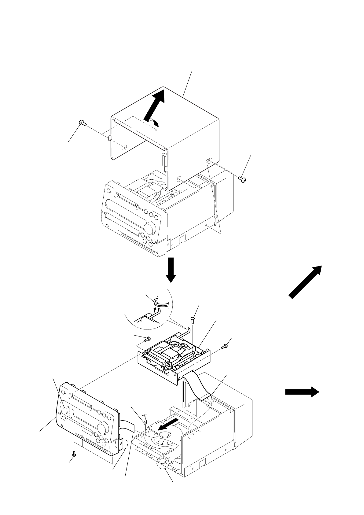
DISASSEMBLY
Note: Follow the disassembly procedure in the numerical order given.
CASE
1
two screws
(case3 TP2)
2
case
1
two screws
(case3 TP2
FRONT PANEL SECTION
6
claw
q;
front panel section
8
screw
(BVTP2.6
3
Remove the cord.
×
8)
2
ground wire
7
5
screw (BVTT3 × 6)
9
MD mechanism deck section
8
screw (BVTP2.6 × 8)
1
wire (flat type) (25 core
(CN107)
BACK PANEL ASS’Y
(Page 22)
18
4
three screws
(BVTT3 × 6)
6
claw
1
wire (flat type)
(29 core) (CN11)
6
claw
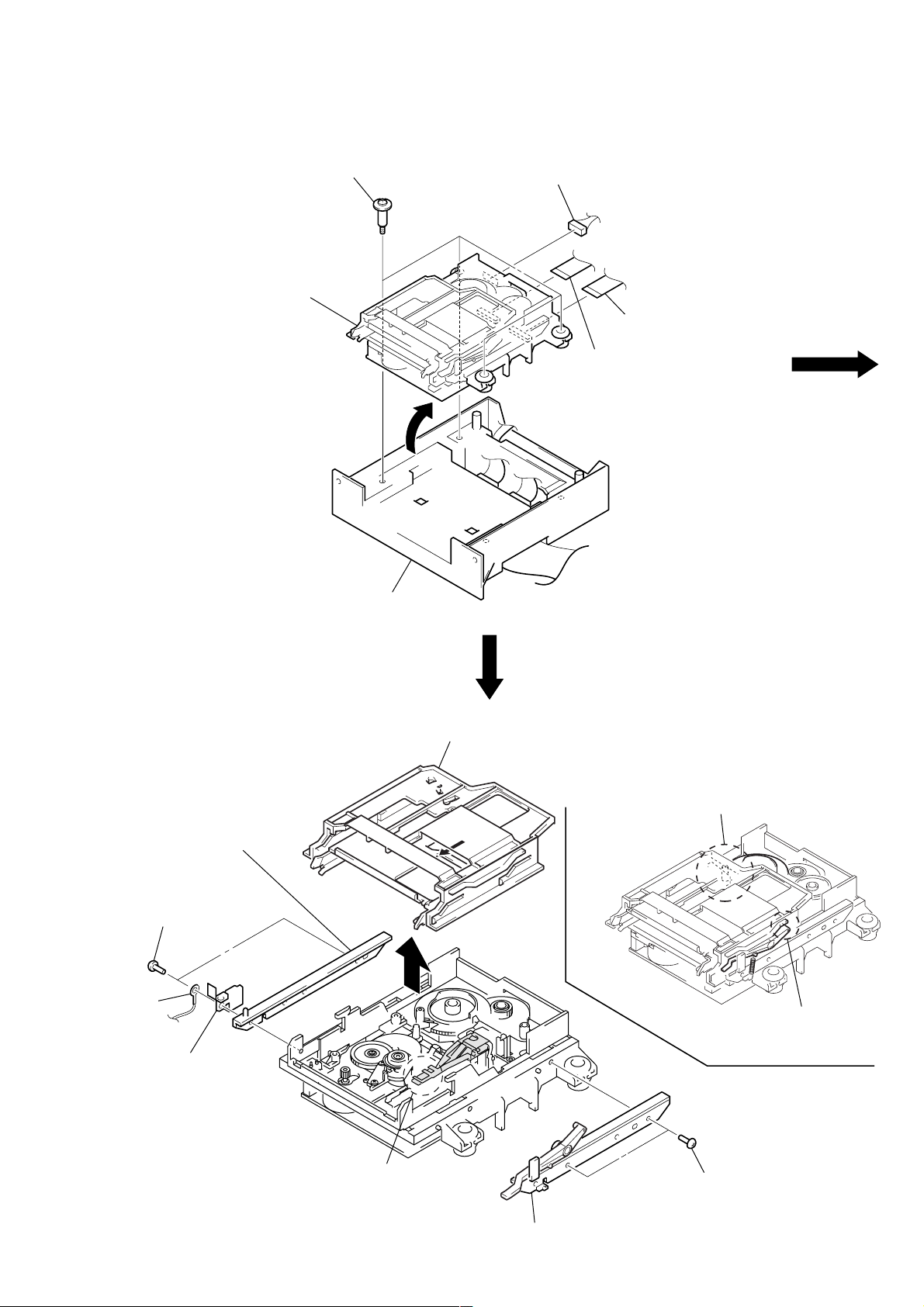
MD MECHANISM DECK (MDM-5GA)
)
2
four step screws
(BVTPWH M3)
6
MD mechanism deck
(MDM-5GA)
3
1
connector (CN601)
4
wire (flat type) (21 core)
(CN102)
4
wire (flat type) (23 core
(CN103)
SLIDER (CAM)
3
1
two screws
(DIA2.6)
2
ground
wire
4
leaf spring
(electrostatic)
bracket (guide L)
bracket (MDM)
5
7
slider (cam)
A
•
NOTE FOR INSTALLATION
OF SLIDER (CAM)
Set the shaft of cam gear to be
at the position in the figure.
Set the shaft of lever
(O/C) to be at the position
in the figure.
When attaching the slider (cam),
this part of the over write head
should be inside arrow
A
.
6
bracket (guide R)
5
two screws
(DIA.2.6)
19
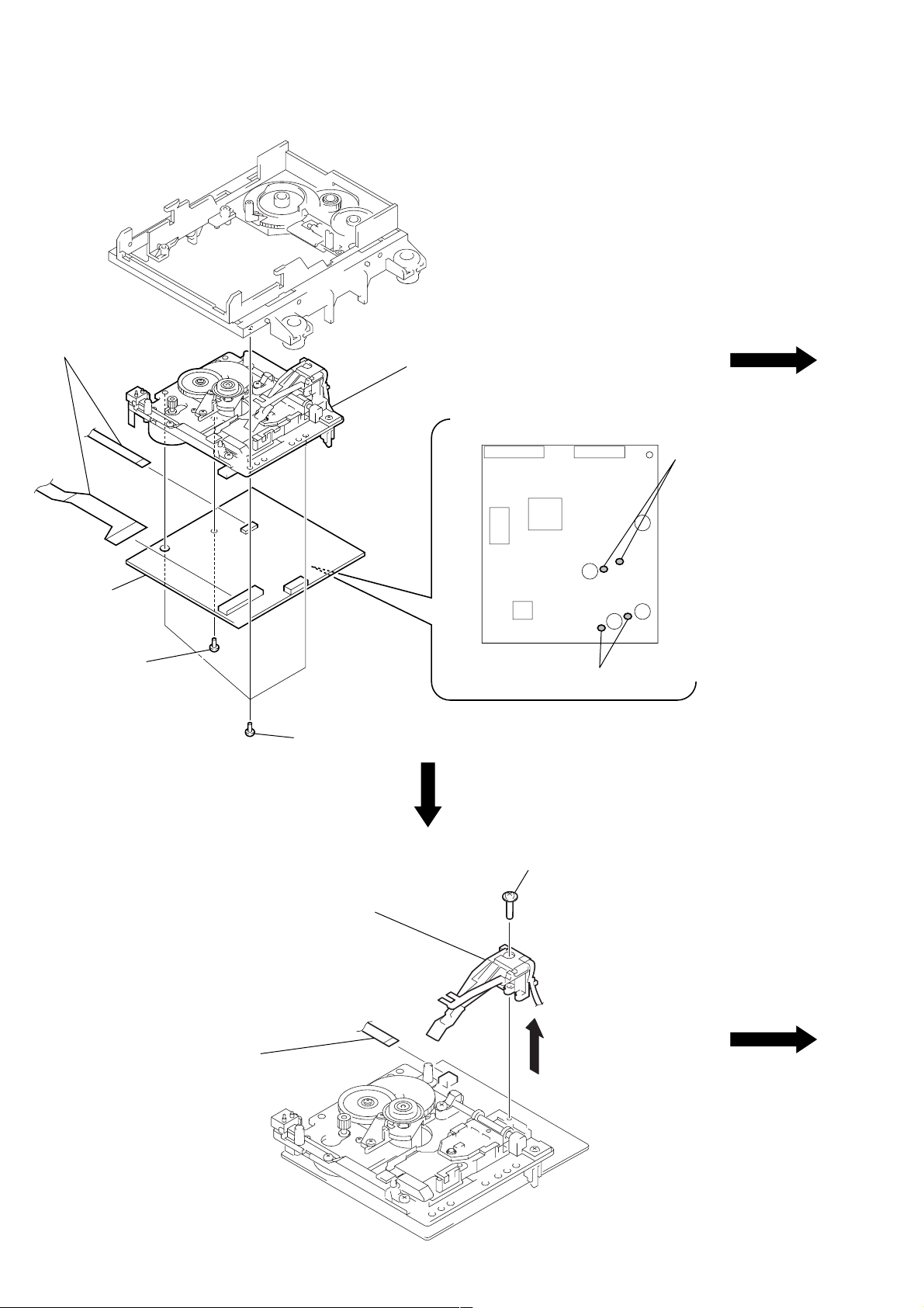
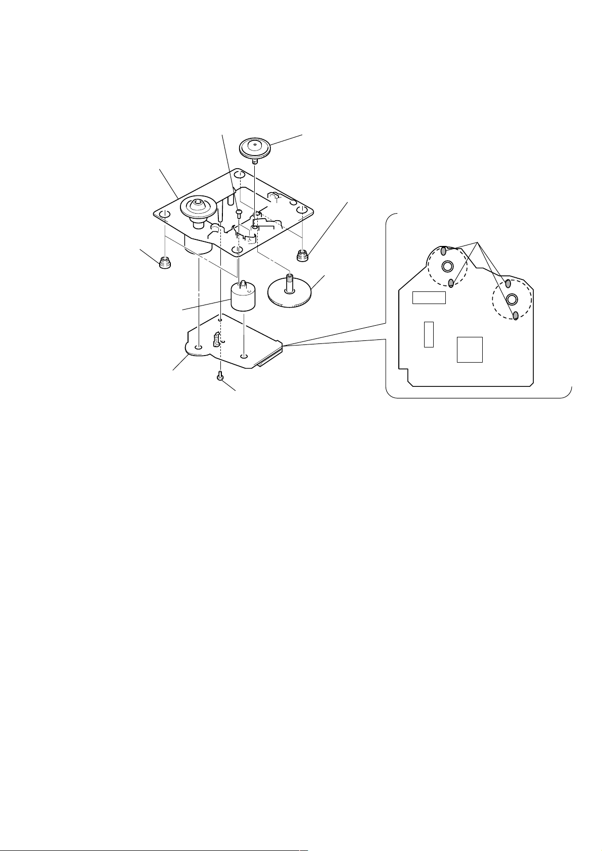
BD (MD) BOARD, BASE UNIT (MBU-5A)
)
5
two flexible boards
(CN101, 104)
7
base unit (MBU-5A)
CN103 CN102
1
Remove two solders
of spindle motor leads
(M901).
6
BD (MD)
board
4
screw (M1.7)
OVER WRITE HEAD (HR901)
3
three screws
(DIA.2.6)
3
over write head
(HR901)
2
Remove two solders
of sled motor leads (M902).
2
screw (P1.7 × 6
20
1
flexible board
(CN104)
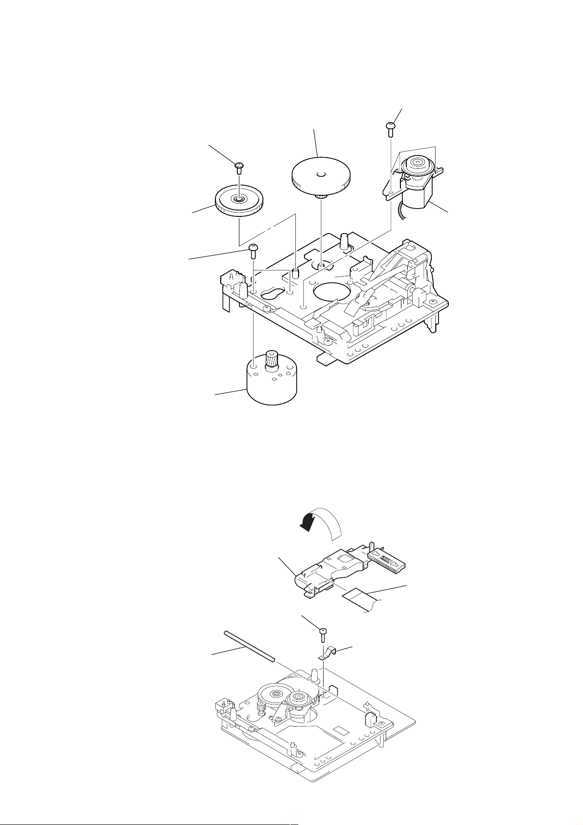
SPINDLE MOTOR ASS’Y (M901), SLED MOTOR ASS’Y (M902)
y
d
3
gear
(SL-B)
1
screw (M1.7)
2
gear (SL-A)
6
two screws
(P1.7 × 2.5)
4
three screws
(B2
×
5)
5
spindle motor ass’
(M901)
7
sled motor ass’y
(M902)
OPTICAL PICK-UP OF MD (KMS-260B/S1NP)
6
optical pick-up
(KMS-260B/S1NP)
1
screw (B2 × 8)
3
main shaft
4
Turn over the optical pick-up.
5
flexible boar
2
leaf spring (shaft)
21
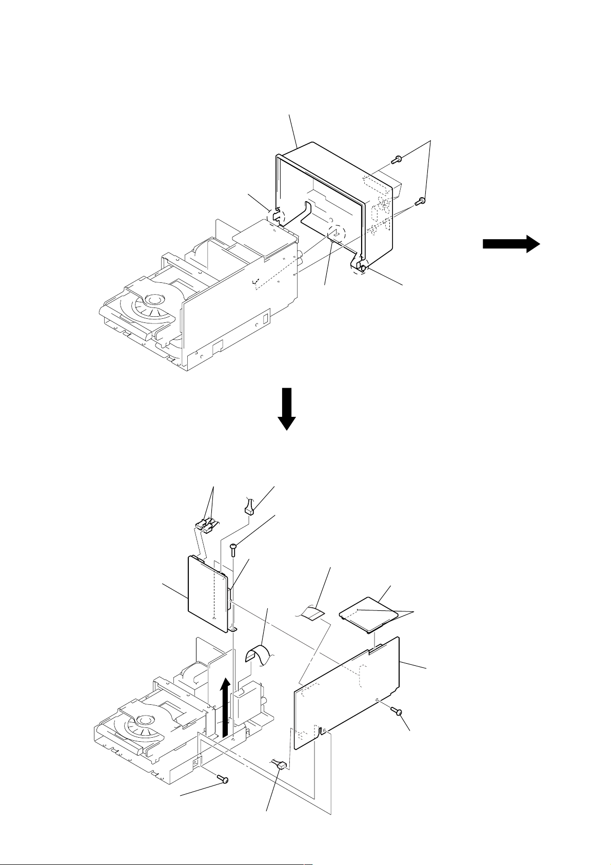
BACK PANEL ASS’Y
)
d
3
4
back panel ass’y
claw
2
claw
1
six screws
(BVTP3
3
claw
×
10
SP BOARD, POWER BOARD AND MAIN BOARD
4
two connectors
(CN991, 992)
9
POWER board
7
4
5
8
connector
(CN994)
3
wire (flat type)
(15 core)
connector (CN993)
two screws (BVTT3 × 6)
3
wire (flat type) (25 core)
(CN109)
2
SP board
1
6
screw (BVTT3 × 6)
two connectors
(CN881, 882)
q;
MAIN boar
22
6
screw (BVTT3 × 6)
4
connector (CN110)
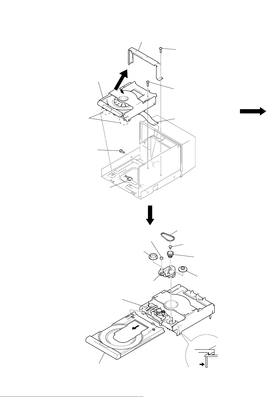
CD MECHANISM DECK (CDM55A-5SBD32)
)
7
CD mechanism deck
(CDM55A-5SB32)
6
two claws
3
screw
(BVTT3
×
6)
4
holder (MDM)
3
screw (BVTT3 × 6)
5
screw (BVTT3 × 6)
1
wire (flat type) (19 core
(CN109)
2
connector
(CN110)
TRAY (CDM), GEAR AND CAM (CDM55)
Note: when drawing out the tray (CDM), refer to
service notes DRAWING OUT THE TRAY
WHEN THE POWER IS OFF on page 6 .
2
Push the claw in the
direction of arrow
8
gear (B)
q;
A
.
7
roller
cam (CDM55)
A
4
belt (CDM55)
5
bushing
6
pulley (LDG)
9
gear (A)
3
Drawing out the tray (CDM).
1
tray (CDM)
2
Release the lock while pressing
this claw in the arrow direction.
23
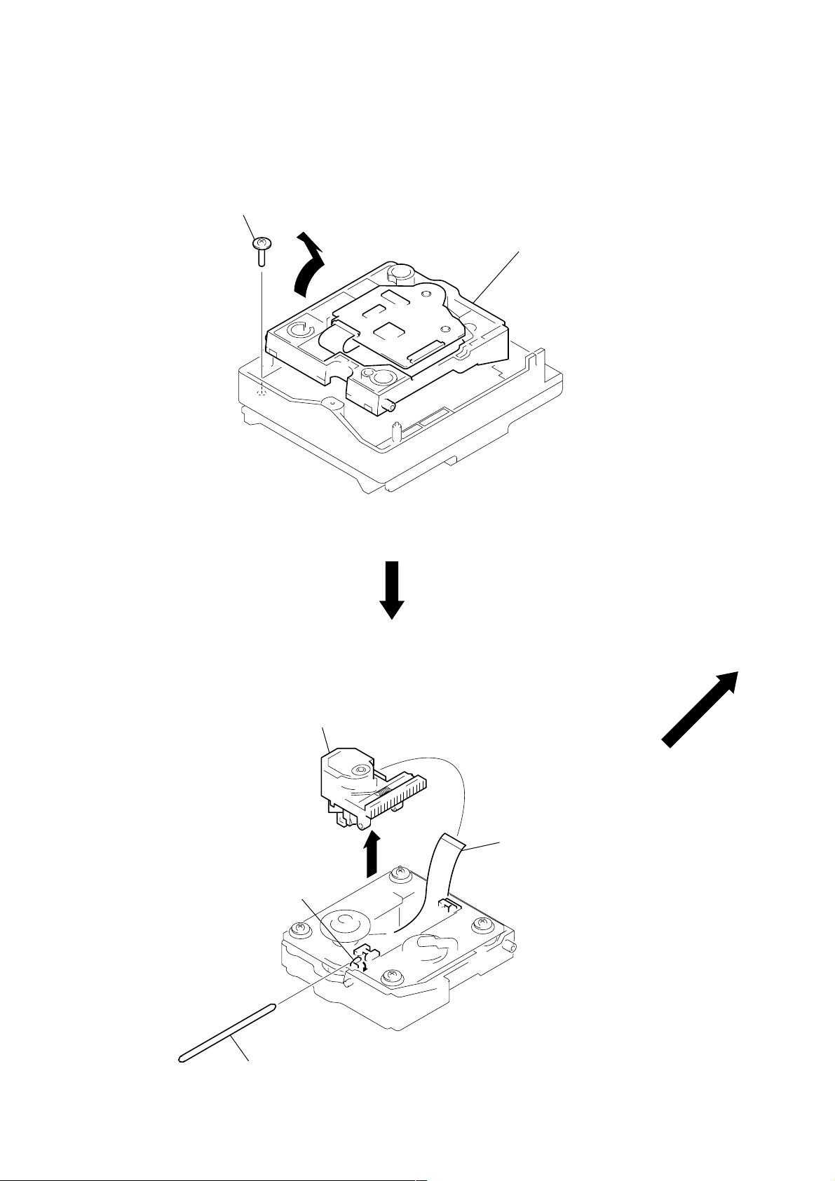
HOLDER (BU) ASS’Y
y
1
floating screw
(PTPWH M2.6)
2
Remove the holder (BU) ass’
in the direction of the arrow.
OPTICAL PICK-UP OF CD (KSS-213BH/Z-NP)
5
optical pick-up
(KSS-213BH/Z-NP)
1
Release the lever in the
direction of arrow
A
3
wire (flat type) (16 core)
4
.
A
24
2
sled shaft
BD (CD) BOARD, BASE (BU-5S) ASS’Y (M101) AND SLED MOTOR ASS’Y (M102)
4
two screws
×
4)
9
base (BU-5S) ass’y (M101)
8
two insulators (BU)
5
sled motor ass’y
(M102)
(B2
6
gear (M)
7
flatness gear
(P)
8
two insulators (BU)
2
Remove the four solders.
M101
M102
3
BD (CD) board
1
screw (BVTP2.6 × 8)
25
SECTION 4
TEST MODE
Note : About “R”
As this unit has only a few buttons, some operations require the use of remote commander (RM-SF3MD/provided with unit: 1-476-068-11)
buttons. These operations are indicated as “R” in this manual.
Example: MENU/NO “R” ...Press the [MENU/NO] button of the remote commander.
4-1. PRECAUTIONS FOR USE OF TEST MODE
• As loading related operations will be performed regardless of the test mode operations being performed, be sure to check that the disc
is stopped before setting and removing it.
Even if the A (MD) button is pressed while the disc is rotating during continuous playback, continuous recording, etc., the disc will
not stop rotating.
Therefore, it will be ejected while rotating.
Be sure to press the A (MD) button after pressing the MENU/NO “R” button and the rotation of disc is stopped.
4-1-1. Recording laser emission mode and operating buttons
• Continuous recording mode (CREC MODE)
• Laser power check mode (LDPWR CHECK)
• Laser power adjustment mode (LDPWR ADJUST)
• Traverse (MO) check (EF MO CHECK)
• Traverse (MO) adjustment (EF MO ADJUST)
• When pressing the zREC button.
4-2. SETTING THE TEST MODE
The following are two methods of entering the test mode.
Procedure 1: 1. Press the I/1 button to turn the power on.
2. Press the [FUNCTION] button to set the MD function.
3. While pressing the s (MD) and zREC buttons, press the I/1 button to enter the MD test mode and display “[Check]”.
When the test mode is set, “[Check]” will be displayed. Press the l m or M L button switches between the
following four groups; ···y [Check] y [Adjust] y [Service] y [Develop] y ···.
Procedure 2: 1. Press the I/1 button to turn the power on.
2. Press the [FUNCTION] button to set the MD function.
3. While pressing the s (MD) and [CD-MD SYNC] buttons, press the I/1 button to enter the MD test mode and display
“TEMP CHECK”.
By setting the test mode using this method, only the “Check” group of method 1 can be executed.
4-3. RELEASING THE TEST MODE
Press the [REPEAT] button.
4-4. BASIC OPERATIONS OF THE TEST MODE
All operations are performed using the l m or M L button , ENTER/YES “R” button, and MENU/NO “R” button.
The functions of these buttons are as follows.
Function name Function
l m , M L buttons Changes parameters and modes
ENTER/YES “R” button Proceeds onto the next step. Finalizes
MENU/NO “R” button Returns to previous step. Stops
input
operations
26
4-5. SELECTING THE TEST MODE
There are 31 types of test modes as shown below. The groups can be switched by pessing the l m or M L button. After
selecting the group to be used, press the ENTER/YES “R” button. After setting a certain group, press the l m or M L button
switches between these modes.
Refer to “Group” in the table for details can be selected.
All items used for servicing can be treated using group S. So be carefully not to enter other groups by mistake.
Display
TEMP CHECK
LDPWR CHECK
EF MO CHECK
EF CD CHECK
FBIAS CHECK
Scurve CHECK
VERIFYMODE
DETRK CHECK
TEMP ADJUST
LDPWR ADJUST
EF MO ADJUST
EF CD ADJUST
FBIAS ADJUST
EEP MODE
MANUAL CMD
SVDATA READ
ERR DP MODE
SLED MOVE
ACCESS MODE
0920 CHECK
HEAD ADJUST
CPLAY2 MODE
CREC2 MODE
ADJ CLEAR
AG Set (MO)
AG Set (CD)
Iop Read
Iop Write
INFORMATION
CPLAY MODE
CREC MODE
Contents
Temperature compensation offset check
Laser power check
Traverse (MO) check
Traverse (CD) check
Focus bias check
S letter check
Non-volatile memory check
Detrack check
Temperature compensation offset adjustment
Laser power adjustment
Traverse (MO) adjustment
Traverse (CD) adjustment
Focus bias adjustment
Non-volatile memory control
Command transmission
Status display
Error history display, clear
Sled check
Access check
Outermost circumference check
Head position check
Same functions as CPLAY MODE
Same functions as CREC MODE
Initialization of non-volatile memory of adjustment value
Auto gain output level adjustment (MO)
Auto gain output level adjustment (CD)
IOP data display
IOP data write
Microprocessing version display
Continuous playback mode
Continuous recording mode
Mark
(X)
(X)
(X)
(X) (!)
(X)
(X)
(X)
(X)
(X)
(X)
(X)
(X)
Group (*)
C: Check
S: Service
Group (*)
CS
CS
CS
CS
CS
C
C
C
AS
AS
AS
AS
AS
D
D
D
S
D
D
D
D
D
D
AS
AS
AS
CS
AS
CS
CASD
CASD
A: Adjust
D: Develop
• For details of each adjustment mode, refer to “5. Electrical Adjustments”.
For details of “ERR DP MODE”, refer to “Self-Diagnosis Function” on page 2.
• If a different mode has been selected by mistake, press the MENU/NO “R” button to release that mode.
• Modes with (X) in the Mark column are not used for servicing and therefore are not described in detail. If these modes are set accidentally, press the MENU/NO “R” button to release the mode immediately. Be especially careful not to set the modes with (!) as they will
overwrite the non-volatile memory and reset it, and as a result, the unit will not operate normally.
27
4-5-1. Operating the Continuous Playback Mode
1. Entering the continuous playback mode
(1) Set the disc in the unit. (Whichever recordable discs or discs for playback only are available.)
(2) Press the
(3) Press the
l m or M L button and display “CPLAY MODE”.
ENTER/YES “R” button to change the display to “CPLAY MID”.
(4) When access completes, the display changes to “C1 = AD = ”.
Note: The numbers “ ” displa yed show you error rates and ADER.
2. Changing the parts to be played back
(1) Press the ENTER/YES “R” button during continuous playback to change the display as below.
“CPLAY MID” t “CPLAY OUT” t “CPLAY IN”
When pressed another time, the parts to be played back can be moved.
(2) When access completes, the display changes to “C1 = AD = ”.
Note: The numbers “ ” displayed show you error rates and ADER.
3. Ending the continuous playback mode
(1) Press the MENU/NO “R” button. The display will change to “CPLAY MODE”.
(2) Press the A (MD) button and take out the disc.
Note: The playback start addresses for IN, MID, and OUT are as follows.
IN : 40h cluster
MID : 300h cluster
OUT: 700h cluster
4-5-2. Operating the Continuous Recording Mode (Use only when performing self-recording/palyback check.)
1. Entering the continuous recording mode
(1) Set a recordable disc in the unit.
(2) Press the l m or M L button and display “CREC MODE”.
(3) Press the ENTER/YES “R” button to change the display to “CREC MID”.
(4) When access completes, the display changes to “CREC ( )” and [ REC] indicator lights up.
Note: The numbers “ ” display ed shows you the recording position addresses.
z
2. Changing the parts to be recorded
(1) When the ENTER/YES “R” button is pressed during continuous recording, the display changes as below.
“CREC MID” t “CREC OUT” t “CREC IN”
z
When pressed another time, the parts to be recorded can be changed.
(2) When access completes, the display changes to “CREC ( )” and [ REC] indicator lights up.
Note: The numbers “ ” display ed shows you the recording position addresses.
[ REC] indicator goes off.
z
3. Ending the continuous recording mode
(1) Press the MENU/NO “R” button. The display changes to “CREC MODE” and [ REC] indicator goes off.
z
(2) Press the A (MD) button and take out the disc.
Note 1: The recording start addresses for IN, MID, and OUT are as follows.
IN : 40h cluster
MID : 300h cluster
OUT: 700h cluster
Note 2: The MENU/NO “R” button can be used to stop recording anytime.
Note 3: Do not perform continuous recording for long periods of time above 5 minutes.
Note 4: During continuous recording, be careful not to apply vibration.
4-5-3. Non-Volatile Memory Mode (EEP MODE)
This mode reads and writes the contents of the non-volatile memory.
It is not used in servicing. If the unit entered this mode accidentally, press the MENU/NO “R” button immediately to release it.
4-6. FUNCTIONS OF OTHER BUTTONS
Function
H S (MD)
s (MD)
M L
l m
CLEAR “R”
PLAY MODE/TUNING MODE
DISP “R”
A (MD)
REPAET
Sets continuous playback when pressed in the STOP state. When pressed during continuous playback, the tracking
servo turns ON/OFF
Stops continuous playback and continuous recording
The sled moves to the outer circumference only when this is pressed
The sled moves to the inner circumference only when this is pressed
Switches between the pit and groove modes when pressed
Switches the spindle servo mode (CLV-S y CLV-A)
Switches the displayed contents each time the button is pressed
Ejects the disc
Releases the test mode
Contents
28
4-7. TEST MODE DISPLAYS
Each time the DISP “R” button is pressed, the display changes in the following order.
1. Mode display
Displays “TEMP ADJUST”, “CPLAYMODE”, etc.
2. Error rate display
Displays the error rate in the following way.
C1 = ssss AD = ss
C1 = Indicates the C1 error.
AD = Indicates ADER.
3. Address display
The address is displayed as follows. (MO: recordable disc, CD: playback only disc)
Press the CLEAR “R” button to switches between the groove display and pit display.
h = ssss s = ssss (MO pit and CD)
h = ssss a = ssss (MO groove)
h = Indicates the header address.
s = Indicates the SUBQ address.
a = Indicates the ADIP address.
Note: “–” is displayed when servo is not imposed.
4. Auto gain display (Not used in servicing)
The auto gain is displayed as follows.
AG = ss/ss[ss]
Mode display
Error rate display
Address display
Auto gain display
(Not used in servicing)
5. Detrack check display (Not used in servicing)
The detrack is displayed as follows.
ADR = sssssss
6. IVR display (Not used in servicing)
The IVR is displayed as follows.
[ss][ss][ss]
MEANINGS OF OTHER DISPLAYS
Display
H (MD)*
S (MD)*
zREC*
SYNC
L.SYNC
OVER
1
REPEAT
DISC
SHUF
MONO
During continuous playback (CLV: ON)
Tracking servo OFF
Recording mode ON
CLV low speed mode
ABCD adjustment completed
Tracking offset cancel ON
Tracking auto gain OK
Focus auto gain OK
High reflection
CLV-S
CLV LOCK
When Lit
* : Indicate by LED.
Detrack check display
(Not used in servicing)
IVR display
(Not used in servicing)
Contents
When Off
STOP (CLV: OFF)
Tracking servo ON
Recording mode OFF
CLV normal mode
Tracking offset cancel OFF
Low reflection
CLV-A
CLV UNLOCK
29
 Loading...