

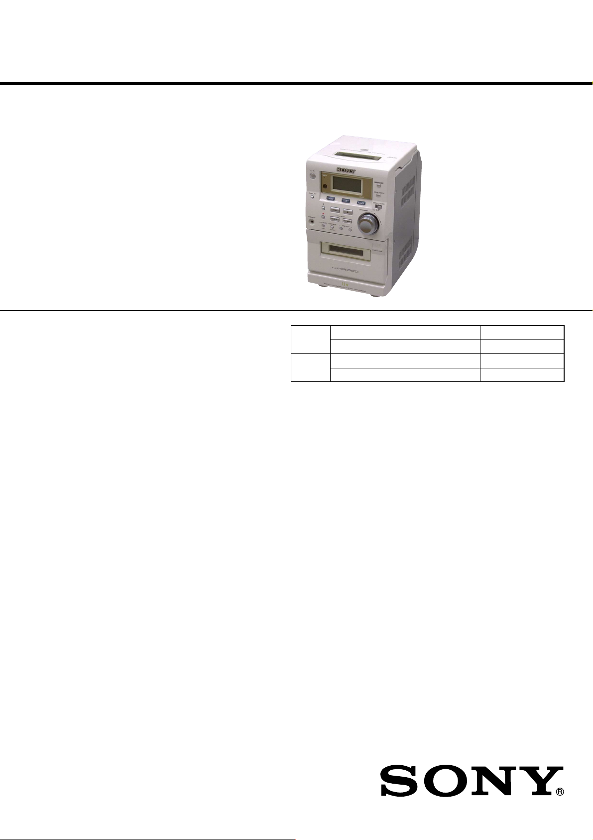
HCD-EP50LIV
SERVICE MANUAL
Ver 1.0 2002.02
HCD-EP50LIV is the amplifier, CD pla yer , tape
deck and tuner section in CMT-EP50LIV.
CD
Section
TAPE
Section
SPECIFICATIONS
US Model
Model Name Using Similar Mechanism HCD-EP50
CD Mechanism Type CS-21SC-1280
Model Name Using Similar Mechanism NEW
T ape Transport Mechanism Type CRL3439
AUDIO POWER SPECIFICATIONS:
POWER OUTPUT AND TOTAL
HARMONIC DISTORTION:
with 8 Ω loads both channels driven, from 120
- 10,000 Hz; rates 12 W per channel minimum
RMS power, with no more than 10% total
harmonic distortion from 250 mW to rated
output.
Amplifier section
The following measured at AC 230 V, 50/60 Hz
DIN power output (rated) 11 + 11 W
Continuous RMS power output (reference)
Outputs
PHONES: Accepts headphones of
(stereo mini jack) 8 Ω or more
SPEAKER: Accepts impedance of 8 to
(8 Ω at 1 kHz, DIN)
12 + 12 W
(8 Ω at 1 kHz, 10% THD)
16 Ω
CD player section
System Compact disc and digital
Laser Semiconductor laser
Frequency response 20 Hz - 20 kHz (±0.5 dB)
Tape player section
Recording system 4-track 2-channel stereo
Frequency response 50 - 13 000 Hz (±3 dB),
Tuner section
FM stereo, FM/AM superheterodyne tuner
FM tuner section
Tuning range 87.5 - 108.0 MHz
Antenna FM lead antenna
Antenna terminal 75 Ω coaxial
Intermediate frequency 10.7 MHz
audio system
(λ=780 nm)
Emission duration:
continuous
using Sony TYPE I
cassette
AM tuner section
Tuning range 530 - 1 710 kHz
Antenna AM loop antenna
Antenna terminal External antenna terminal
Intermediate frequency 450 kHz
General
Power requirements: 120 V AC, 60 Hz
Power consumption: 35 W
Dimensions (w/h/d):
Mass: Approx. 3.4 kg
Supplied accessories: AM loop antenna (1)
Design and specifications are subject to change
(with the interval set at
10 kHz)
531 - 1 710 kHz
(with the interval set at
9 kHz)
Approx. 145 × 238 × 234 mm
Remote Commander (1)
Batteries (2)
FM lead antenna (1)
9-873-634-01 Sony Corporation
2002B0500-1 Home Audio Company
C 2002.02 Published by Sony Engineering Corporation
MICRO Hi-Fi COMPONENT SYSTEM

HCD-EP50LIV
TABLE OF CONTENTS
1. SERVICING NOTES ................................................ 4
2. GENERAL ................................................................... 5
3. DISASSEMBLY
3-1. Disassembly Flow ........................................................... 7
3-2. Front Panel Section ......................................................... 8
3-3. MAIN Board ................................................................... 8
3-4. CD Cabinet Section......................................................... 9
3-5. CD Mechanism Deck (CS-21SC-1280) ......................... 9
3-6. Tape Mechanism Deck (CRL3439) ................................ 10
3-7. Cassette Lid ..................................................................... 10
4. MECHANICAL ADJUSTMENTS....................... 11
5. ELECTRICAL ADJUSTMENTS......................... 11
6. DIAGRAMS
6-1. Block Diagram – TUNER Section – ............................. 15
6-2. Block Diagram – TAPE DECK Section – ..................... 16
6-3. Block Diagram – MAIN Section – ................................ 17
6-4. Block Diagram
– DISPLAY/POWER SUPPLY Section – ...................... 18
6-5. Note for Printed Wiring Boards and
Schematic Diagrams ....................................................... 19
6-6. Schematic Diagram – FM TUNER Section – ............... 19
6-7. Schematic Diagram – MAIN Board (1/3) – .................. 20
6-8. Schematic Diagram – MAIN Board (2/3) – .................. 21
6-9. Schematic Diagram
– MAIN (3/3)/HEADPHONE Boards – ......................... 22
6-10. Printed Wiring Boards
– MAIN/HEADPHONE Boards –.................................. 23
6-11. Printed Wiring Board – DISPLAY Board – .................. 24
6-12. Schematic Diagram – DISPLAY Board – ..................... 25
6-13. Printed Wiring Board – POWER Board –..................... 26
6-14. Schematic Diagram – POWER Board – ........................ 27
6-15. IC Pin Function Description ........................................... 31
CAUTION
Use of controls or adjustments or performance of procedures
other than those specified herein may result in hazardous radiation exposure.
7. EXPLODED VIEWS
7-1. Cabinet Section ............................................................... 33
7-2. Front Panel Section-1...................................................... 34
7-3. Front Panel Section-2...................................................... 35
7-4. CD Cabinet Section......................................................... 36
8. ELECTRICAL PARTS LIST ............................... 37
2
HCD-EP50LIV
r
Notes on chip component replacement
• Never reuse a disconnected chip component.
• Notice that the minus side of a tantalum capacitor may be damaged by heat.
Flexible Circuit Board Repairing
• Keep the temperature of the soldering iron around 270 ˚C during repairing.
• Do not touch the soldering iron on the same conductor of the
circuit board (within 3 times).
• Be careful not to apply force on the conductor when soldering
or unsoldering.
SAFETY CHECK-OUT
After correcting the original service problem, perform the following safety check before releasing the set to the customer:
Check the antenna terminals, metal trim, “metallized” knobs,
screws, and all other exposed metal parts for AC leakage.
Check leakage as described below.
LEAKAGE TEST
The AC leakage from any exposed metal part to earth ground and
from all exposed metal parts to any exposed metal part having a
return to chassis, must not exceed 0.5 mA (500 microamperes.).
Leakage current can be measured by any one of three methods.
1. A commercial leakage tester , such as the Simpson 229 or RCA
WT -540A. Follo w the manufacturers’ instructions to use these
instruments.
2. A battery-operated AC milliammeter. The Data Precision 245
digital multimeter is suitable for this job.
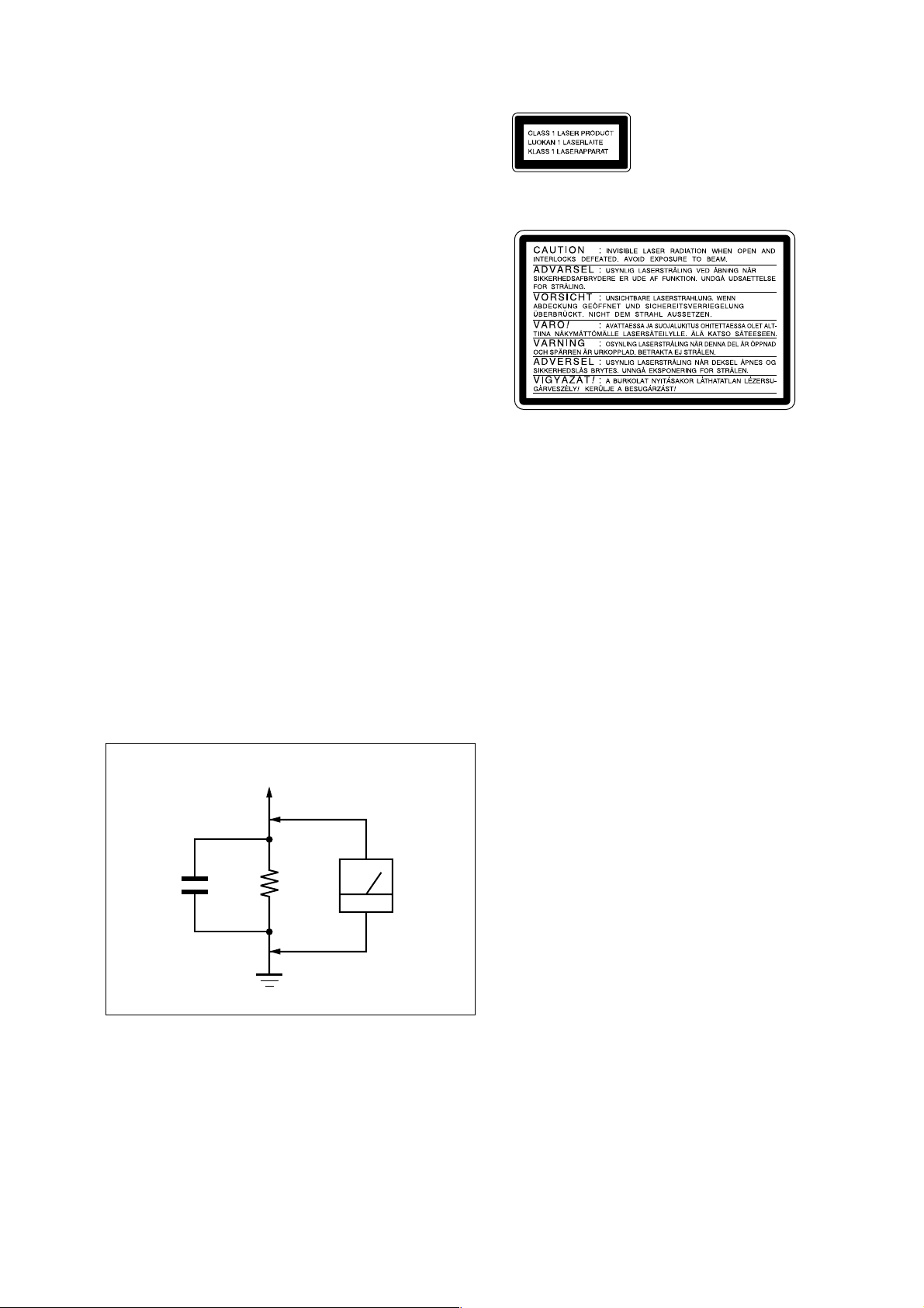
3. Measuring the voltage drop across a resistor by means of a
VOM or battery-operated AC voltmeter. The “limit” indication is 0.75 V, so analog meters must have an accurate lowvoltage scale. The Simpson 250 and Sanwa SH-63Trd are examples of a passive VOM that is suitable. Nearly all battery
operated digital multimeters that have a 2 V A C range are suitable. (See Fig. A)
This appliance is classified as
a CLASS 1 LASER product.
The CLASS 1 LASER
PRODUCT MARKING is
located on the rear exterior.
The following caution label is located inside the unit.
To Exposed Metal
Parts on Set
1.5 k
0.15 µF
Fig. A. Using an AC voltmeter to check AC leakage.
SAFETY-RELATED COMPONENT WARNING!!
COMPONENTS IDENTIFIED BY MARK 0 OR DOTTED
LINE WITH MARK 0 ON THE SCHEMATIC DIAGRAMS
AND IN THE PARTS LIST ARE CRITICAL TO SAFE
OPERATION. REPLACE THESE COMPONENTS WITH
SONY PARTS WHOSE PART NUMBERS APPEAR AS
SHOWN IN THIS MANUAL OR IN SUPPLEMENTS PUBLISHED BY SONY.
Ω
Earth Ground
AC
voltmete
(0.75 V)
3
HCD-EP50LIV
SECTION 1
SERVICING NOTES
NOTES ON HANDLING THE OPTICAL PICK-UP
BLOCK OR BASE UNIT
The laser diode in the optical pick-up block may suffer electrostatic break-down because of the potential difference generated
by the charged electrostatic load, etc. on clothing and the human
body.
During repair, pay attention to electrostatic break-down and also
use the procedure in the printed matter which is included in the
repair parts.
The flexible board is easily damaged and should be handled with
care.
NOTES ON LASER DIODE EMISSION CHECK
The laser beam on this model is concentrated so as to be focused
on the disc reflective surface by the objective lens in the optical
pick-up block. Therefore, when checking the laser diode emission, observe from more than 30 cm away from the objectiv e lens.
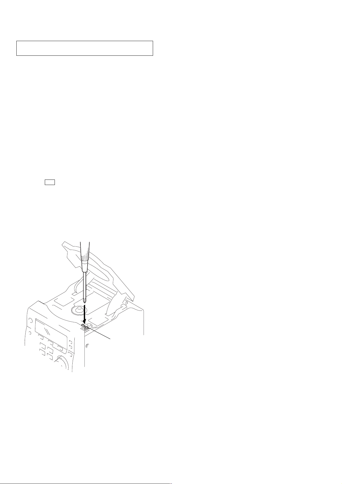
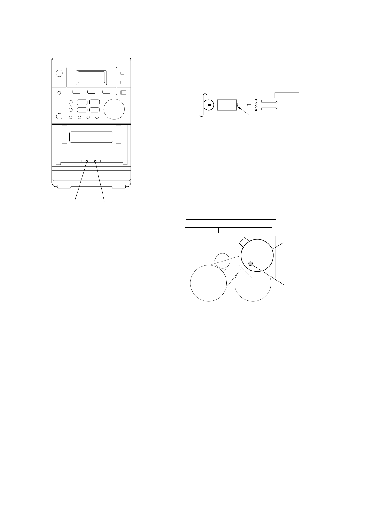
LASER DIODE AND FOCUS SEARCH OPERATION
CHECK
1. Press the I/1 button to the power ON with no disc inserted
and press the [CD] button.
2. Open the lid for CD.
3. Turn on SW300 as following figure.
4. Confirm the laser diode emission while observing the objecting lens. When there is no emission, Auto Power Control circuit or Optical Pick-up is broken.
Objective lens moves up and down five times for the focus
search.
SW300
4
SECTION 2
GENERAL
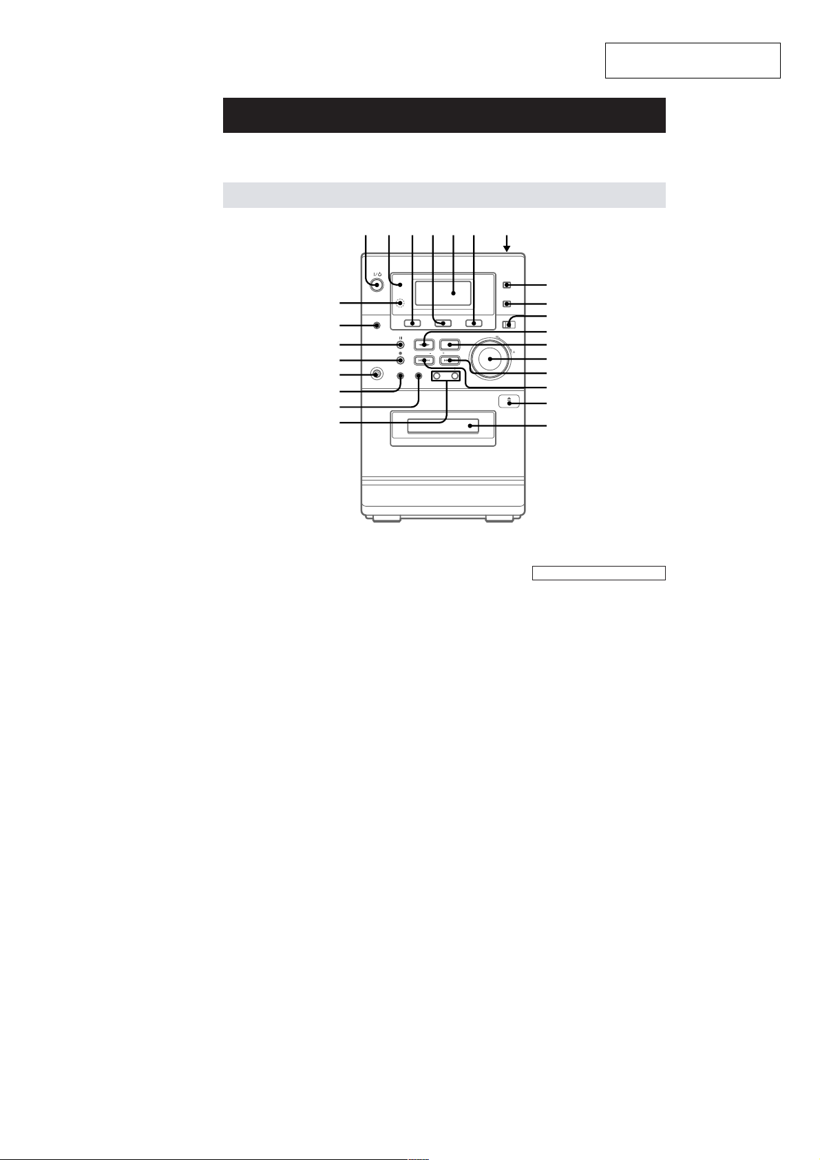
Parts Identification
The items are arranged in alphabetical order.
Refer to the pages indicated in parentheses ( ) for details.
Main unit
1 2 3456 7
wg
wf
wd
ws
wa
w;
ql
qk
HCD-EP50LIV
This section is extracted from
instruction manual.
8
9
q;
qa
qs
qd
qf
qg
qh
qj
Cassette compartment qj (13)
CD 4 (8, 9, 14)
DISPLAY wf (9, 11)
Display Window 5 (8, 9, 10)
ENTER ql (7, 9, 10, 12)
ISS 0 (14)
MEGA BASS 8 (16)
MONO STEREO 0 (11)
MUSIC MENU 9 (16)
PHONES jack wa
PLAY MODE w; (8, 9)
PRESET +/– qk (10, 11, 12)
DIR w; (12, 13, 14, 15)
Remote sensor wg
TAPE 3 (13)
TIMER indicator 2 (15, 18)
TUNER 6 (10, 11, 14)
TUNER MEM ql (10)
TUNING + qf (10, 11, 12, 15)
TUNING – qg (10, 11, 12, 15)
VOLUME control qd
BUTTON DESCRIPTIONS
@/1 (power) 1 (7, 11, 15, 18)
CD
. m (go back) qg (8, 9)
M > (go forward) qf (8, 9)
nN (play) qa (8, 9)
X (pause) wd (8)
Z PUSH OPEN/CLOSE 7 (8)
x (stop) qs (8, 9)
TAPE
M > (fast forward) qf (13)
X (pause) wd (13)
nN (play) qa (13, 14, 15)
z (recording) ws (14, 15)
. m (rewind) qg (13)
Z PUSH OPEN/CLOSE qh (13)
x (stop) qs (13, 14)
5
HCD-EP50LIV
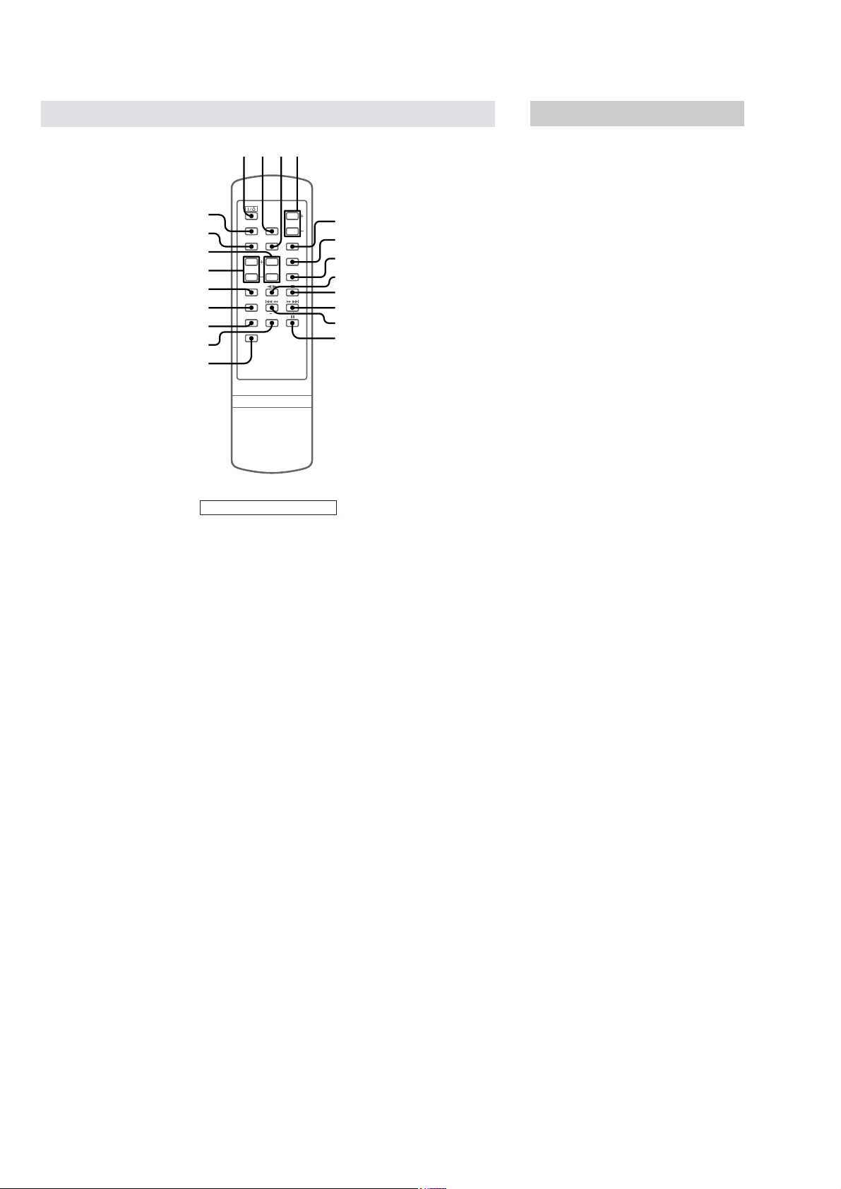
Remote Control
CD 3 (8, 9, 14)
CLOCK/TIMER qg (7, 15, 17)
DISPLAY qh (9, 11)
MEGA BASS 2 (16)
MUSIC MENU wa (16)
PLAY MODE/DIR qj (8, 9, 12,
13, 14, 15)
PRESET +/– qk (10, 11)
REPEAT 7 (8)
SLEEP qd (17)
TAPE w; (13)
TIMER ON/OFF qf (15, 18)
TUNER/BAND 5 (10, 11, 14)
TUNER MEM/ENTER 6 (7, 9,
10, 12, 15, 17, 18)
TUNING/CLOCK/TIMER +/–
ql (7, 10, 11, 12, 15, 17, 18)
VOLUME +/– 4
1234
wa
w;
ql
qk
qj
qh
qg
qf
qd
BUTTON DESCRIPTIONS
M (fast forward) > (go
forward) 0 (8, 9, 13)
. (go back) m (rewind) qa
(8, 9, 13)
X (pause) qs (8, 13)
nN (play) 8 (8, 9, 13, 14, 15)
`/1 (power) 1 (7, 11, 15, 18)
x (stop) 9 (8, 9, 13, 14)
5
6
7
8
9
q;
qa
qs
Setting the time
1
Turn on the system.
2
Press CLOCK/TIMER on the remote.
When you set the clock for the first time, go
to step 5.
3
Press CLOCK/TIMER on the remote
repeatedly until “SET CLK” appears in
the display.
4
Press TUNER MEM/ENTER on the
remote.
5
Press TUNING/CLOCK/TIMER + or – on
the remote repeatedly to set the hour.
6
Press TUNER MEM/ENTER on the
remote.
7
Press TUNING/CLOCK/TIMER + or – on
the remote repeatedly to set the minute.
8
Press TUNER MEM/ENTER on the
remote.
To reset the system clock
Start over from step 1.
Note
The clock settings are canceled when you disconnect
the power cord or if a power failure occurs.
6
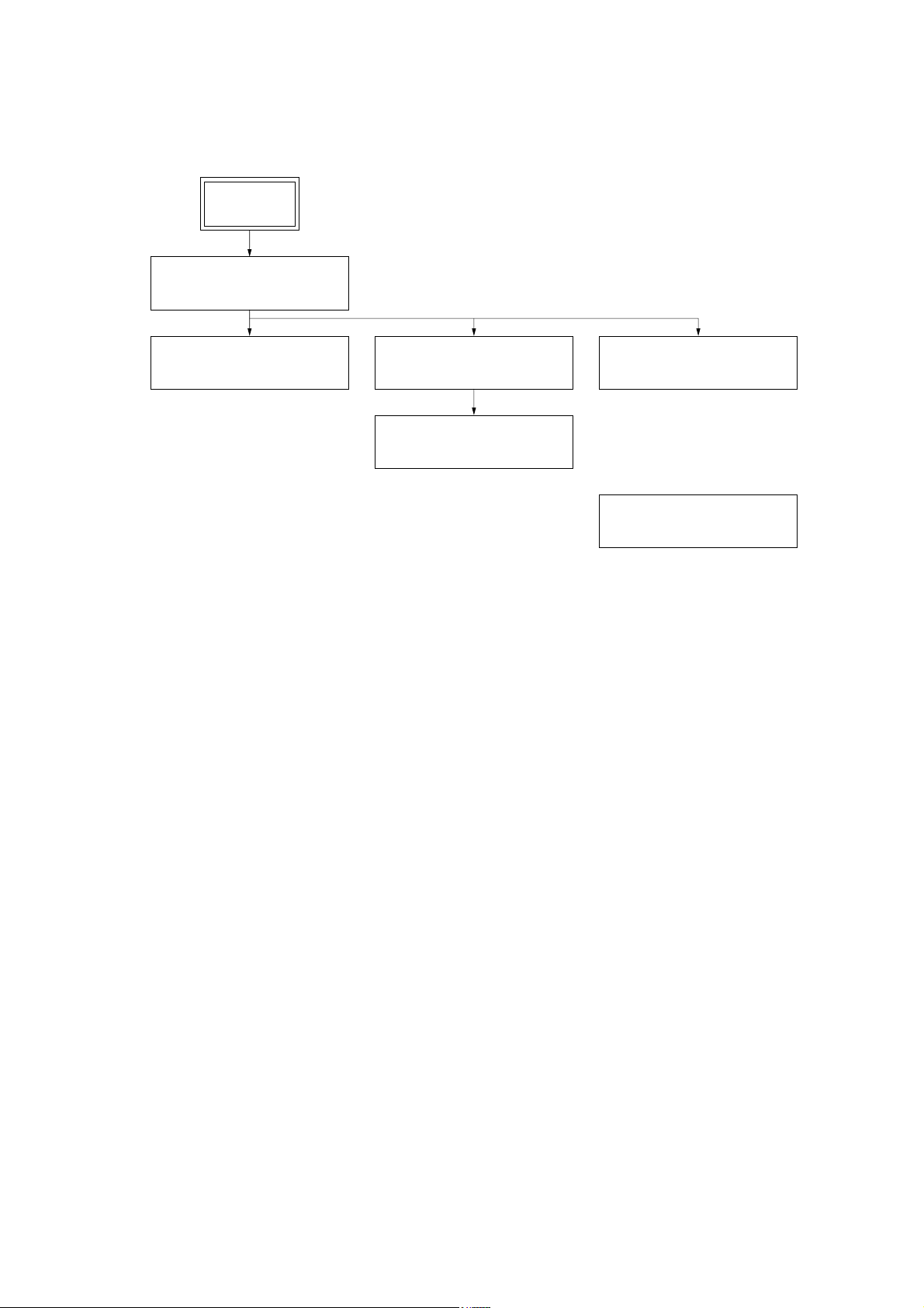
• This set can be disassembled in the order shown below.
3-1. DISASSEMBLY FLOW
SET
3-2. FRONT PANEL SECTION
(Page 8)
HCD-EP50LIV
SECTION 3
DISASSEMBLY
3-3. MAIN BOARD
(Page 8)
3-4. CD CABINET SECTION
(Page 9)
3-5. CD MECHANISM DECK
(CS-21SC-1280)
(Page 9)
3-6. TAPE MECHANISM DECK
(CRL3439)
(Page 10)
3-7. CASSETTE LID
(Page 10)
7
HCD-EP50LIV
)
r
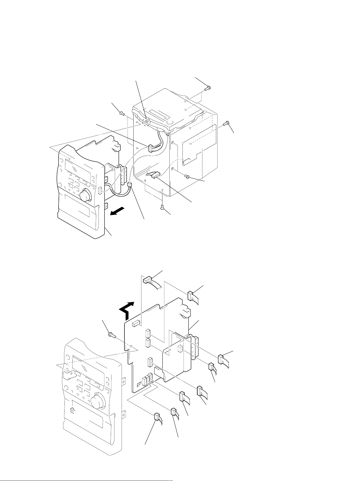
Note: Follow the disassembly procedure in the numerical order given.
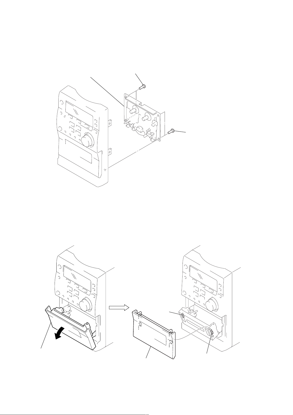
3-2. FRONT PANEL SECTION
4
claw
3
two screws
×
5)
(K3
6
connector
(CN3)
1
two screws
(BTP2.6
×
10)
2
two screws
(BVTP3
×
10
3-3. MAIN BOARD
7
screw
(BTP2.6
5
9
front panel section
8
×
8)
8
connector
(SW300)
3
1
connector
(CN9)
7
two screws
×
5)
(K3
3
two screws
(K3
connector
(CN601)
1
connector
(CN4)
9
main board
×
5)
2
connecto
(CN11)
3
connector
(CN7)
4
connector
(CN201)
5
connector
(CN5)
6
connector
6
connector
(CN14)
(CN15)
8
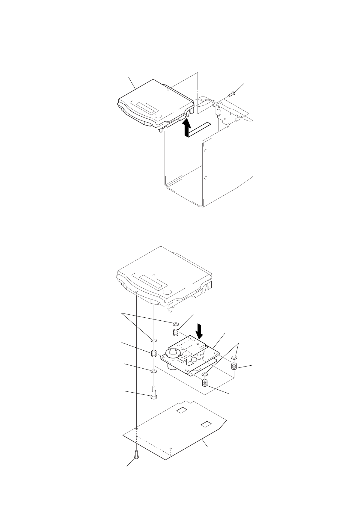
3-4. CD CABINET SECTION
)
2
CD cabinet section
1
two screws
(BTP2.6
HCD-EP50LIV
×
8
3-5. CD MECHANISM DECK (CS-21SC-1280)
6
two spring clamps
7
vibration proof rubber
(pink)
4
four fiber washers
3
four pulley screws
7
vibration proof rubber
(ORG)
5
8
CD mechanism deck (CS-21SC-1280)
6
two spring clamps
7
vibration proof rubber
(ORG)
7
vibration proof rubber
(pink)
1
two screws
(BVTP3 × 10)
2
plastic cover
9
HCD-EP50LIV
)
3-6. TAPE MECHANISM DECK (CRL3439)
2
tape mechanism deck (CRL3439)
1
two screws
(BVTP3
×
10)
1
two screws
(BVTP3
×
10
3-7. CASSETTE LID
1
Open the cassette lid.
3
cassette lid
2
claw
2
claw
10
SECTION 4
MECHANICAL ADJUSTMENTS
HCD-EP50LIV
SECTION 5
ELECTRICAL ADJUSTMENTS
PRECAUTION
1. Clean the following parts with a denatured-alcohol-moistened
swab :
record/playback head pinch roller
erase head rubber belts
capstan idlers
2. Demagnetize the record/playback head with a head demagnetizer. (Do not bring the head magnetizer close to the erase head.)
3. Do not use a magnetized screwdriver for the adjustments.
4. After the adjustments, apply suitable locking compound to the
parts adjusted.
5. The adjustments should be performed with the rated power
supply voltage unless otherwise noted.
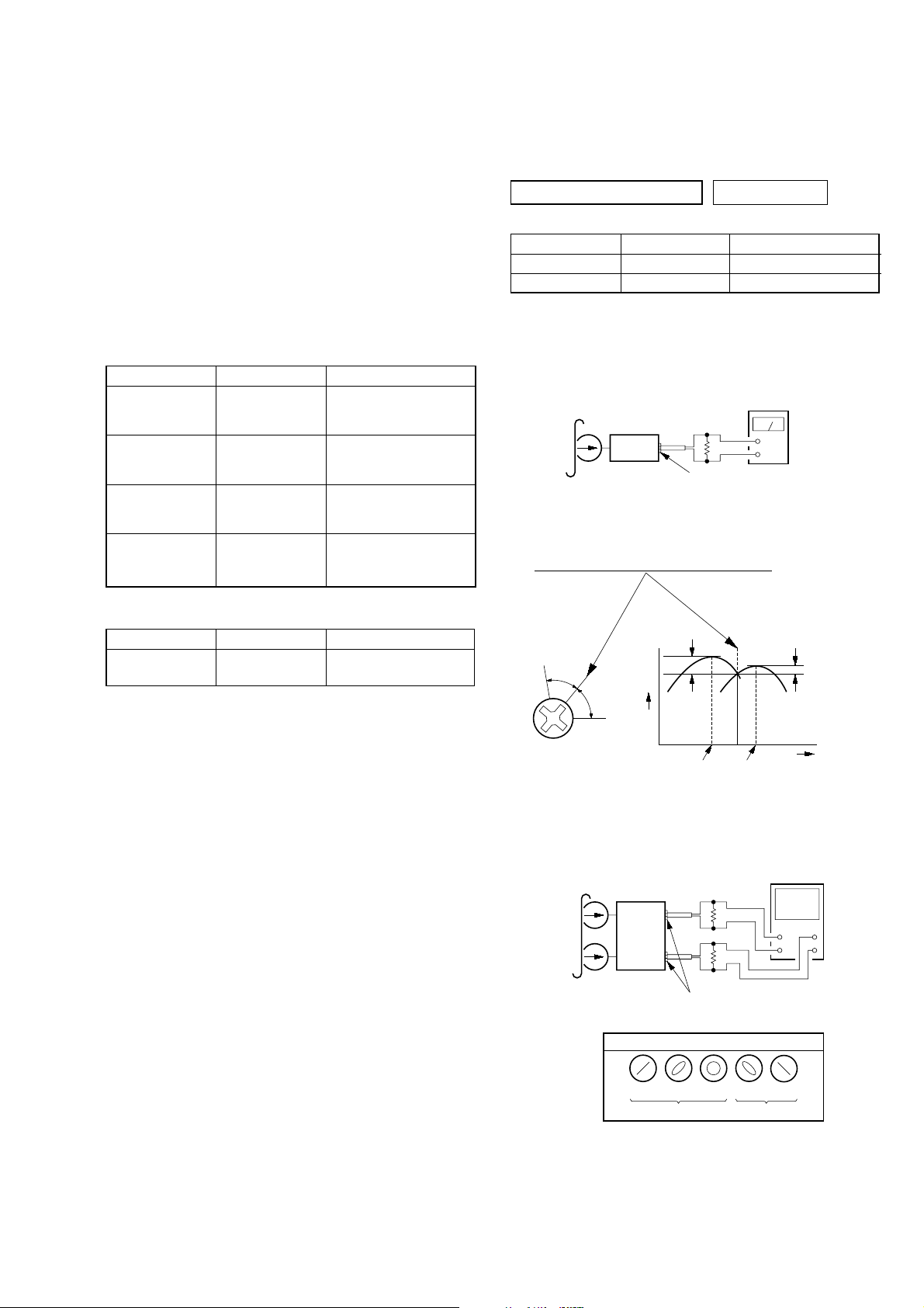
• Torque Measurement
Mode Torque Meter Meter Reading
FWD CQ-102C (30 – 70 g•cm)
FWD
Back Tension
FF CQ-201B (more than 60 g•cm)
REW CQ-201B (more than 60 g•cm)
CQ-102C (1.5 – 5.5 g•cm)
2.95 – 6.86 mN•m
(0.42 – 0.97 oz•inch)
0.15 – 5.39 mN•m
(0.021 – 0.076 oz•inch)
more than 5.89 mN•m
(more than 0.83 oz•inch)
more than 5.89 mN•m
(more than 0.83 oz•inch)
PRECAUTION
1. Setting
MEGA BASS switch : OFF
TAPE DECK SECTION 0 dB=0.775 V
Test tape
Type Signal Used for
P-4-A100 10 kHz, –10 dB Head Azimuth Adjustment
WS-48B 3 kHz, 0 dB Tape Speed Adjustment
Record/Playback Head Azimuth Adjustment
Procedure:
1. Mode: Playback (FWD)
test tape
P-4-A100
(10 kHz, –10 dB)
47 k
set
MAIN board
SPEAKER terminal (CN17)
2. Turn the adjustment screw and check output peaks. If the peaks
do not match for L-CH and R-CH, turn the adjustment screw
so that outputs match within 1dB of peak.
level meter
Ω
+
–
• Tape T ension Measurement
Mode Tension Meter Meter Reading
FWD CQ-403A
more than 100 g
(more than 3.53 oz)
L-CH
peak
Output
level
R-CH
Screw
position
peak
3. Mode: Playback (FWD)
test tape
P-4-A100
(10 kHz, –10 dB)
L-CH
set
R-CH
within
1dB
L-CH
peak
MAIN board
SPEAKER terminal (CN17)
screen pattern
47 k
47 k
R-CH
peak
Ω
Ω
oscilloscope
V
+
–
within
1dB
H
+
–
Screw
position
in phase
45
°
good wrong
90
°
135 °180
°
4. Repeat step 1 to 3 in playback (REV) mode.
5. After the adjustments, apply suitable locking compound to the
parts adjusted.
11
HCD-EP50LIV
)
Adjustment Location:Record/Playback Head. Tape Speed Adjustment
Setting:
Function: TAPE
test tape
WS-48B
(3 kHz, 0 dB)
set
Procedure:
1. Playback WS-48B (tape center) in the FWD state.
2. Adjsut the volume in CAPSTAN/REEL motor so that the frequency counter reading becomes 3,000 Hz.
Specified Value: 2,910 to 3,090 Hz
3. Confirm that the frequency at the beginning and that at the
end of tape winding are between 2,955 to 3,045 Hz.
forward
Note: Refer to “3-7. CASSETTE LID” (see page 10)
reverse
Adjustment Location:
frequency counter
47 k
Ω
+
–
MAIN board
SPEAKER terminal (CN17
CAPSTAN/REEL
motor
Tape Speed
Adjustment
Sample Value of Wow and Flutter: 0.3% or less W. RMS (JIS)
(WS-48B)
12
HCD-EP50LIV
)
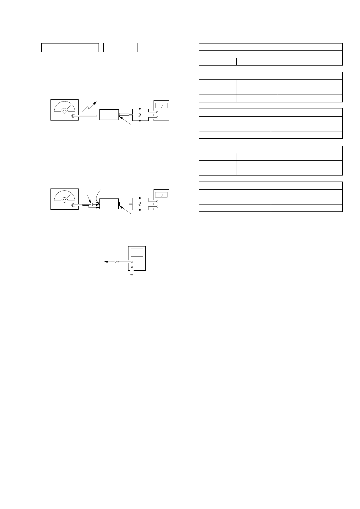
)
TUNER SECTION 0 dB=1 µV
[AM]
Setting:
Function : TUNER
Band switch: AM
AM RF signal
generator
30% amplitude
modulation by
400 Hz signal
Output level: as low as possible
[FM]
Setting:
Function : TUNER
Band switch: FM
FM RF signal
generator
22.5 kHz frequency
deviation by 400 Hz
signal
Output level: as low as possible
Put the lead-wire
antenna close to
the set.
set
MAIN board
0.01 µF
FM ANT
set
level meter
32
Ω
+
–
MAIN board
SPEAKER terminal (CN17
level meter
32
Ω
+
–
MAIN board
SPEAKER terminal (CN17
AM IF ADJUSTMENT
Adjust for a maximum reading on level meter
T1 450 kHz
AM FREQUENCY COVERAGE ADJUSTMENT
Adjustment Part Frequency Display Reading on Digital Voltmeter
T8 530 kHz 1.3 ± 0.1 V
Confirmation 1,710 kHz 7.8 ± 0.5 V
AM TRACKING ADJUSTMENT
Adjust for a maximum reading on level meter
T6 603 kHz
TC1 1,404 kHz
FM FREQUENCY COVERAGE ADJUSTMENT
Adjustment Part Frequency Display Reading on Digital Voltmeter
L901 87.5 MHz 2.4 ± 0.1 V
Confirmation 108 MHz 6.8 ± 0.5 V
FM TRACKING ADJUSTMENT
Adjust for a maximum reading on level meter
L902 90.1 MHz
TC901 106.1 MHz
Adjustment Location: MAIN board (See page 14)
digital voltmeter
MAIN board
TP (FM VT)
TP (AM VT)
100 k
Ω
• Repeat the procedures in each adjustment several times, and the
frequency coverage and tracking adjustments should be finally
done by the trimmer capacitors.
13
HCD-EP50LIV
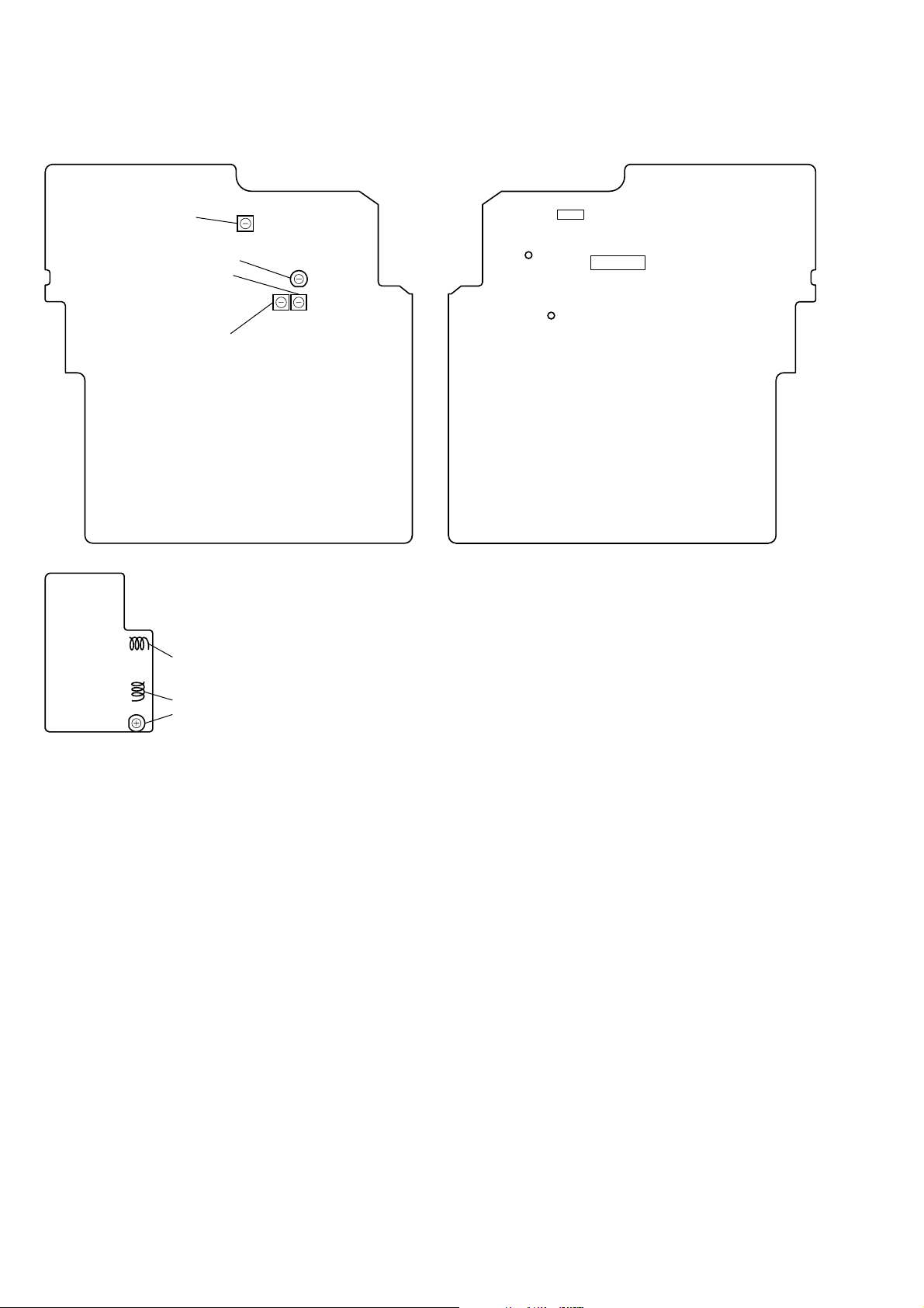
Adjustment Location and Connecting Points
– MAIN BOARD (Component Side) –
T1
AM IF Adjustment
AM Tracking Adjustment
Coverage Adjustment
TC1
{
T6
T8
AM Frequency
– MAIN BOARD (Conductor Side) –
U2
TP
(FM VT)
TP
(AM VT)
U1
L901 FM Frequency Coverage Adjustment
L902
TC901
FM Tracking Adjustment
}
14
 Loading...