

Sony HCDEC-69-I, HCDEC-79-I, HCDEC-99-I Service manual
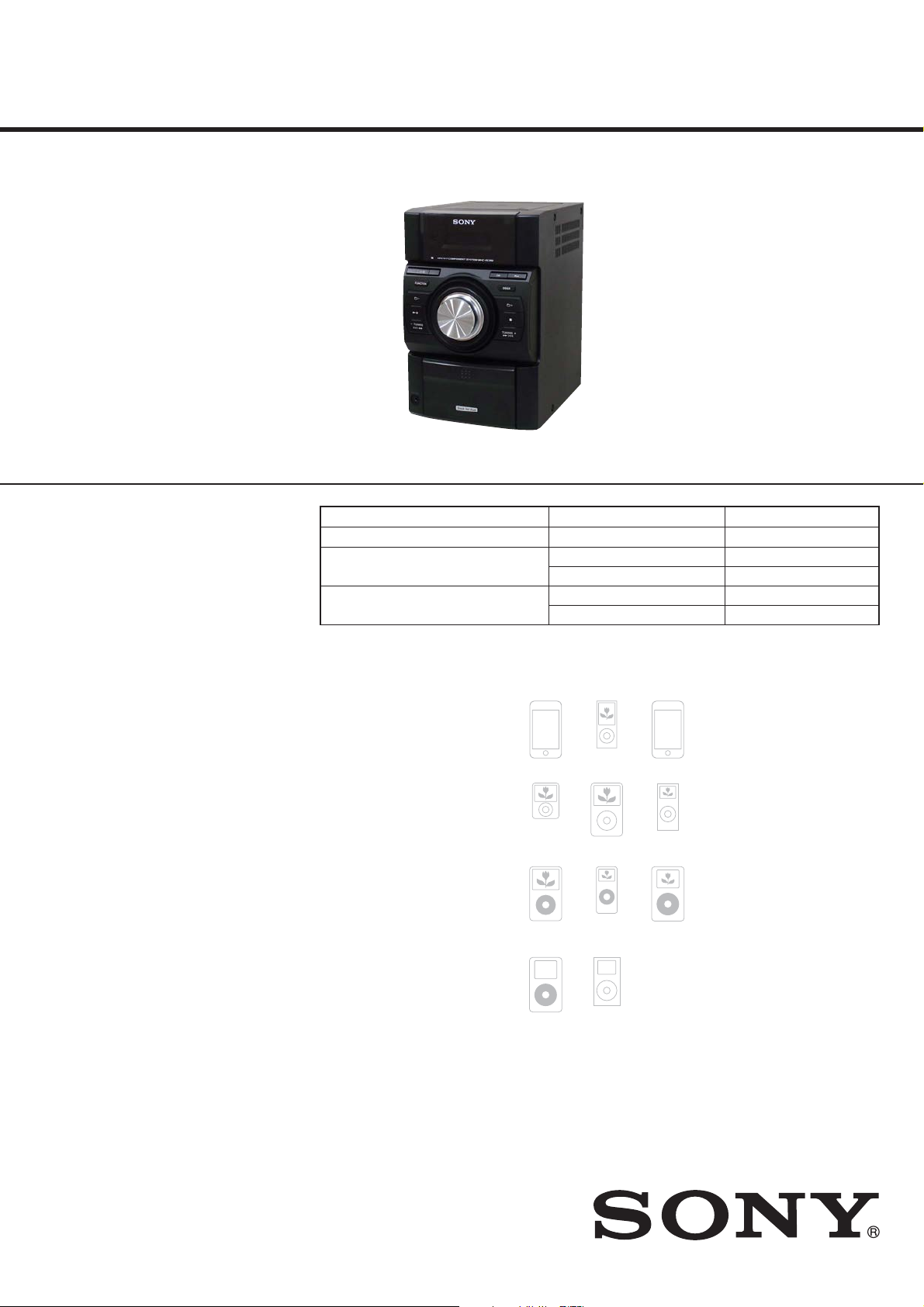
HCD-EC69i/EC79i/EC99i
SERVICE MANUAL
Ver. 1.1 2009.05
• HCD-EC69i is the amplifi er, CD player, tuner
and iPod section in MHC-EC69i.
• HCD-EC79i is the amplifi er, CD player, tuner
and iPod section in MHC-EC79i.
• HCD-EC99i is the amplifi er, CD player, tuner
and iPod section in MHC-EC99i. Photo: HCD-EC69i
iPod is a trademark of Apple Inc., registered in the U.S.
and other countries.
MPEG Layer-3 audio coding technology and patents
licensed from Fraunhofer IIS and omson.
All other trademarks and registered trademarks are of
their respective holders. In this manual,
are not specied.
TM
and ® marks
Model Name Using Similar Mechanism
Mechanism Type
Base Unit Name
Optical Pick-up Block Name
US Model
Canadian Model
UK Model
Australian Model
CDM76A-K6BD90-WOD NEW
EC79i: UK, Australian/EC99i CDM76A-K6BD90-WOD
EC69i/EC79i: US, Canadian BU-K8BD90-WOD
EC79i: UK, Australian/EC99i BU-K6BD90-WOD
EC69i/EC79i: US, Canadian KSM-213CDP
EC79i: UK, Australian/EC99i KSM-213DCP
Main unit
AUDIO POWER SPECIFICATIONS
POWER OUTPUT AND TOTAL HARMONIC DISTORTION:
(HCD-EC99i, HCD-EC79i e United States model only)
Low channel
With 8 ohm loads, both channels driven, from 120 – 10,000 Hz; rated 60 watts
per channel minimum RMS power, with no more than 0.7% total harmonic
distortion from 250 milliwatts to rated output.
High channel
With 8 ohm loads, both channels driven, from 2,000 – 13,000 Hz; rated
60 watts per channel minimum RMS power, with no more than 0.7% total
harmonic distortion from 250 milliwatts to rated output.
AUDIO POWER SPECIFICATIONS
POWER OUTPUT AND TOTAL HARMONIC DISTORTION:
(HCD-EC69i e United States model only)
With 6 ohm loads, both channels driven, from 120 – 10,000 Hz; 30 watts
per channel minimum RMS power, with no more than 0.7% total harmonic
distortion from 250 milliwatts to rated output.
Amplier section
HCD-EC99i
Front Speaker
RMS output power (reference):
Low channel
95 W + 95 W (per channel at 8 Ω, 1 kHz, 10% THD)
High channel
95 W + 95 W (per channel at 8 Ω, 8 kHz, 10% THD)
Subwoofer
RMS output power (reference):
150 W (at 4 Ω, 80 Hz, 10% THD)
HCD-EC79i
RMS output power (reference):
Low channel
95 W + 95 W (per channel at 8 Ω, 1 kHz, 10% THD)
High channel
95 W + 95 W (per channel at 8 Ω, 8 kHz, 10% THD)
HCD-EC69i
RMS output power (reference):
50 W + 50 W (per channel at 6 Ω, 1 kHz, 10% THD)
Inputs (except for HCD-EC69i)
PC IN (stereo mini jack): Sensitivity 800 mV, impedance 22 kilohms
Outputs
PHONES (stereo mini jack): Accepts headphones with an impedance of 8 Ω
or more
SPEAKER: impedance
HCD-EC99i/EC79i: 8 Ω
HCD-EC69i: 6 Ω
SUBWOOFER OUT (HCD-EC99i only): impedance 4 Ω
SPECIFICATIONS
CD player section
System: Compact disc and digital audio system
Laser Diode Properties
Emission Duration: Continuous
Laser Output*: Less than 44.6μW
is output is the value measurement at a distance of 200mm from the
*
objective lens surface on the Optical Pick-up Block with 7mm aperture.
Frequency response: 20 Hz 20 kHz
Signal-to-noise ratio: More than 90 dB
Dynamic range: More than 88 dB
Tuner section
FM stereo, FM/AM superheterodyne tuner
Antenna:
FM lead antenna
AM loop antenna
FM tuner section:
Tuning range
North American model: 87.5 108.0 MHz (100 kHz step)
Other models: 87.5 108.0 MHz (50 kHz step)
Intermediate frequency: 10.7 MHz
AM tuner section:
Tuning range
North American model:
530 1,710 kHz (with 10 kHz tuning interval)
531 1,710 kHz (with 9 kHz tuning interval)
Australian model:
531 1,710 kHz (with 9 kHz tuning interval)
530 1,710 kHz (with 10 kHz tuning interval)
UK model:
531 1,602 kHz (with 9 kHz tuning interval)
Intermediate frequency: 450 kHz
iPod section
Compatible iPod models:
iPod touch 2nd
generation
iPod nano 3rd
generation
(video)
iPod 5th
generation
(video)
iPod 4th
generation
iPod nano 4th
generation
(video)
iPod classic
iPod nano 1st
generation
iPod mini
iPod touch 1st
generation
iPod nano 2nd
generation
(aluminum)
iPod 4th
generation
(color display)
General
Power requirements:
North American model: AC 120 V, 60 Hz
Australian model: AC 230 240 V, 50/60 Hz
UK model: AC 230 V, 50/60 Hz
Power consumption:
HCD-EC99i
250 W
(0.5 W at the Power Saving Mode)
HCD-EC79i
200 W
(0.5 W at the Power Saving Mode)
HCD-EC69i
80 W
(0.5 W at the Power Saving Mode)
Dimensions (w/h/d) (excl. speakers):
HCD-EC99i
Approx. 200 × 311 × 375 mm
HCD-EC79i (Australian and UK models only)
Approx. 200 × 311 × 375 mm
HCD-EC79i (North American model only)
Approx. 200 × 306 × 375 mm
HCD-EC69i
Approx. 200 × 306 × 305 mm
Mass (excl. speakers):
HCD-EC99i
Approx. 6.2 kg
HCD-EC79i (Australian and UK models only)
Approx. 6.0 kg
HCD-EC79i (North American model only)
Approx. 5.7 kg
HCD-EC69i
Approx. 3.8 kg
Design and specications are subject to change without notice.
9-889-427-02
2009E05-1
2009.05
©
COMPACT DISC RECEIVER
Sony Corporation
Audio&Video Business Group
Published by Sony Techno Create Corporation

HCD-EC69i/EC79i/EC99i
NOTES ON CHIP COMPONENT REPLACEMENT
• Never reuse a disconnected chip component.
• Notice that the minus side of a tantalum capacitor may be damaged by heat.
FLEXIBLE CIRCUIT BOARD REPAIRING
• Keep the temperature of soldering iron around 270 °C during
repairing.
• Do not touch the soldering iron on the same conductor of the
circuit board (within 3 times).
• Be careful not to apply force on the conductor when soldering
or unsoldering.
CAUTION
Use of controls or adjustments or performance of procedures
other than those specifi ed herein may result in hazardous radia-
tion exposure.
This appliance is classifi ed as
a CLASS 1 LASER product.
This marking is located on the
rear exterior.
SAFETY CHECK-OUT
After correcting the original service problem, perform the following safety check before releasing the set to the customer:
Check the antenna terminals, metal trim, “metallized” knobs,
screws, and all other exposed metal parts for AC leakage.
Check leakage as described below.
LEAKAGE TEST
The AC leakage from any exposed metal part to earth ground and
from all exposed metal parts to any exposed metal part having a
return to chassis, must not exceed 0.5 mA (500 microamperes.).
Leakage current can be measured by any one of three methods.
1. A commercial leakage tester, such as the Simpson 229 or RCA
WT-540A. Follow the manufacturers’ instructions to use these
instruments.
2. A battery-operated AC milliammeter. The Data Precision 245
digital multimeter is suitable for this job.
3. Measuring the voltage drop across a resistor by means of a
VOM or battery-operated AC voltmeter. The “limit” indication
is 0.75 V, so analog meters must have an accurate low-voltage
scale. The Simpson 250 and Sanwa SH-63Trd are examples
of a passive VOM that is suitable. Nearly all battery operated
digital multimeters that have a 2 V AC range are suitable. (See
Fig. A)
To Exposed Metal
Parts on Set
SAFETY-RELATED COMPONENT WARNING!
COMPONENTS IDENTIFIED BY MARK 0 OR DOTTED LINE
WITH MARK 0 ON THE SCHEMATIC DIAGRAMS AND IN
THE PARTS LIST ARE CRITICAL TO SAFE OPERATION.
REPLACE THESE COMPONENTS WITH SONY PARTS
WHOSE PART NUMBERS APPEAR AS SHOWN IN THIS
MANUAL OR IN SUPPLEMENTS PUBLISHED BY SONY.
ATTENTION AU COMPOSANT AYANT RAPPORT
À LA SÉCURITÉ!
AC
1.5 kΩ0.15 μF
Earth Ground
voltmeter
(0.75 V)
Fig. A. Using an AC voltmeter to check AC leakage.
LES COMPOSANTS IDENTIFIÉS PAR UNE MARQUE 0 SUR
LES DIAGRAMMES SCHÉMATIQUES ET LA LISTE DES
PIÈCES SONT CRITIQUES POUR LA SÉCURITÉ DE FONCTIONNEMENT. NE REMPLACER CES COMPOSANTS QUE
PAR DES PIÈCES SONY DONT LES NUMÉROS SONT DONNÉS DANS CE MANUEL OU DANS LES SUPPLÉMENTS
PUBLIÉS PAR SONY.
2

TABLE OF CONTENTS
HCD-EC69i/EC79i/EC99i
1. SERVICING NOTES ............................................. 4
2. GENERAL .................................................................. 7
3. DISASSEMBLY
3-1. Disassembly Flow ........................................................... 9
3-2. Side Panel (L)/(R)
(HCD-EC69i/EC79i: US, Canadian) .............................. 10
3-3. Top Panel Block
(HCD-EC69i/EC79i: US, Canadian) .............................. 10
3-4. Ornament Plate (Dock) or iPod Assy .............................. 11
3-5. Base (Dock) .................................................................... 12
3-6. MAIN Board ................................................................... 12
3-7. Front Panel Block
(HCD-EC69i/EC79i: US, Canadian) .............................. 13
3-8. Base Unit Block (BU-K8BD90-WOD)
(HCD-EC69i/EC79i: US, Canadian) .............................. 13
3-9. Optical Pick-Up Block (KSM-213CDP)
(HCD-EC69i/EC79i: US, Canadian) .............................. 14
3-10. Side Panel (L)/(R)
(HCD-EC79i: UK, Australian/EC99i) ............................ 14
3-11. Top Panel Block
(HCD-EC79i: UK, Australian/EC99i) ............................ 15
3-12. CD Mechanism Deck (CDM76A-K6BD90-WOD)
(HCD-EC79i: UK, Australian/EC99i) ............................ 15
3-13 MAIN Board (HCD-EC79i: UK, Australian/EC99i) ...... 16
3-14. Front Panel Block
(HCD-EC79i: UK, Australian/EC99i) ............................ 16
3-15. Base Unit (BU-K6BD90-WOD)
(HCD-EC79i: UK, Australian/EC99i) ............................ 17
3-16. Optical Pick-Up Block (KSM-213DCP)
(HCD-EC79i: UK, Australian/EC99i) ............................ 17
3-17. Belt (CDM76) (HCD-EC79i: UK, Australian/EC99i) .... 18
4. TEST MODE ............................................................ 19
6. DIAGRAMS
6-1. Block Diagram - CD, TUNER Section - ........................ 24
6-2. Block Diagram - MAIN Section - ................................... 25
6-3. Block Diagram
- PANEL, POWER SUPPLY Section - ........................... 26
6-4. Printed Wiring Board - CD Board - ................................ 28
6-5. Schematic Diagram - CD Board - ................................... 29
6-6. Schematic Diagram - MAIN Board (1/2) - ..................... 30
6-7. Schematic Diagram - MAIN Board (2/2) - ..................... 31
6-8. Printed Wiring Board - MAIN Board - ........................... 32
6-9. Printed Wiring Boards - AMP Section -.......................... 33
6-10. Schematic Diagram - 2CH-4CH AMP Board - ............... 34
6-11. Schematic Diagram - 3CH AMP Board (EC99i) - .......... 35
6-12. Printed Wiring Boards - PANEL Section - ..................... 36
6-13. Schematic Diagram - PANEL Section - .......................... 37
6-14. Printed Wiring Boards - AUDIO IN/OUT, KEY,
POWER SUPPLY Section - ............................................ 38
6-15. Schematic Diagram - AUDIO IN/OUT, KEY,
POWER SUPPLY Section - ............................................ 39
7. EXPLODED VIEWS
7-1. Overall Section (HCD-EC69i) ........................................ 46
7-2. Overall Section (HCD-EC79i/EC99i) ............................ 47
7-3. Top Panel Section (HCD-EC69i/EC79i: US, CND) ....... 48
7-4. Top Panel Section (HCD-EC79i: UK, AUS/EC99i) ....... 49
7-5. Front Panel Section ......................................................... 50
7-6. iPod Dock Section .......................................................... 51
7-7. MAIN Board, Chassis Section (HCD-EC69i) ................ 52
7-8. MAIN Board Section (HCD-EC79i/EC99i) ................... 53
7-9. Chassis Section (HCD-EC79i/EC99i) ............................ 54
8. ELECTRICAL PARTS LIST .............................. 55
Accessories are given in the last of the electrical parts list.
5. ELECTRICAL ADJUSTMENTS ........................ 23
3
HCD-EC69i/EC79i/EC99i
Ver. 1.1
SECTION 1
SERVICING NOTES
NOTES ON HANDLING THE OPTICAL PICK-UP
BLOCK OR BASE UNIT
The laser diode in the optical pick-up block may suffer electrostatic break-down because of the potential difference generated by
the charged electrostatic load, etc. on clothing and the human body.
During repair, pay attention to electrostatic break-down and also
use the procedure in the printed matter which is included in the
repair parts.
The fl exible board is easily damaged and should be handled with
care.
NOTES ON LASER DIODE EMISSION CHECK
The laser beam on this model is concentrated so as to be focused
on the disc refl ective surface by the objective lens in the optical
pickup block. Therefore, when checking the laser diode emission,
observe from more than 30 cm away from the objective lens.
UNLEADED SOLDER
Boards requiring use of unleaded solder are printed with the leadfree mark (LF) indicating the solder contains no lead.
(Caution: Some printed circuit boards may not come printed with
the lead free mark due to their particular size)
: LEAD FREE MARK
Unleaded solder has the following characteristics.
• Unleaded solder melts at a temperature about 40 °C higher
than ordinary solder.
Ordinary soldering irons can be used but the iron tip has to be
applied to the solder joint for a slightly longer time.
Soldering irons using a temperature regulator should be set to
about 350 °C.
Caution: The printed pattern (copper foil) may peel away if
the heated tip is applied for too long, so be careful!
• Strong viscosity
Unleaded solder is more viscous (sticky, less prone to fl ow)
than ordinary solder so use caution not to let solder bridges
occur such as on IC pins, etc.
• Usable with ordinary solder
It is best to use only unleaded solder but unleaded solder may
also be added to ordinary solder.
RELEASING THE DISC TRAY LOCK
(EC79i: UK, Australian/EC99i)
The disc tray lock function for the antitheft of an demonstration
disc in the store is equipped.
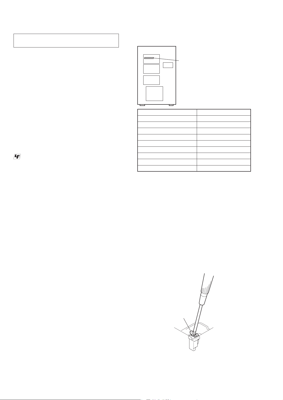
MODEL IDENTIFICATION
- Back Panel -
Power
Voltage
Indication
Model Power Voltage Indication
EC69i: US and Canadian model
EC69i: UK model
EC69i: Australian model
EC79i: US and Canadian model
EC79i: UK model
EC79i: Australian model
EC99i: US and Canadian model
EC99i: UK model
EC99i: Australian model
120V - 60Hz 80W
230V - 50/60Hz 80W
230–240V - 50/60Hz 80W
120V - 60Hz 200W
230V - 50/60Hz 200W
230–240V - 50/60Hz 200W
120V - 60Hz 250W
230V - 50/60Hz 250W
230–240V - 50/60Hz 250W
LASER DIODE AND FOCUS SEARCH OPERATION
CHECK (EC69i/EC79i: US, Canadian models)
During normal operation of the equipment, emission of the laser
diode is prohibited unless the upper lid is closed while turning on
the SW351. (push switch type)
The following checking method for the laser diode is operable.
• Method
Emission of the laser diode is visually checked.
1. Open the upper lid.
2. Push the SW351 as shown in Fig.1.
Note: Do not push the detection lever strongly, or it may be bent or
damaged.
3. Check the object lens for confi rming normal emission of the
laser diode. If not emitting, there is a trouble in the automatic
power control circuit or the optical pick-up.
In this operation, the object lens will move up and down 2
times along with inward motion for the focus search.
Releasing Procedure:
1. Press [
] button to turn the power on.
?/1
2. Press the [FUNCTION] button to select CD function.
3. While pressing the [x] button, press the [Z] button for more 5
seconds).
4. The message “UNLOCKED” is displayed and the disc tray is
unlocked.
Note: When “LOCKED” is displayed, the slot lock is not released by turn-
ing power on/off with the [?/1] button.
NOTE OF REPLACING THE LOADING BOARD
(EC79i: UK, Australian/EC99i)
When the LOADING board is damaged, exchange the entire
CDM76A Assy.
4
SW351
Fig. 1. Method to push the SW351
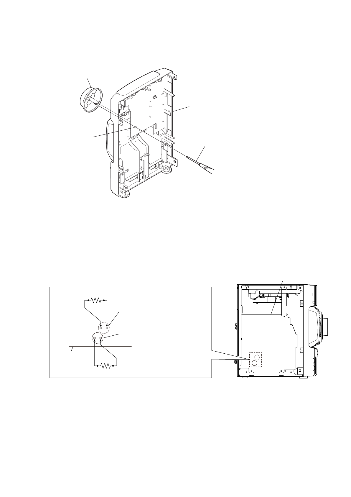
HOW TO REMOVE THE KNOB (VOL)
knob (VOL)
HCD-EC69i/EC79i/EC99i
front panel block
(back view)
hole
Push the knob (VOL) by flat-head screwdriver.
CAPACITOR DISCHARGE FOR ELECTRIC SHOCK PREVENTION
Note: Please take out the top panel block and side panel (L/R) from a set refer to DISASSEMBLY (from Page 10).
In checking the MAIN board, make a capacitor discharge
of C622 and C626 for electric shock prevention.
800 :/2 W
MAIN board
MAIN board
C626
C622
800 :/2 W
5
HCD-EC69i/EC79i/EC99i
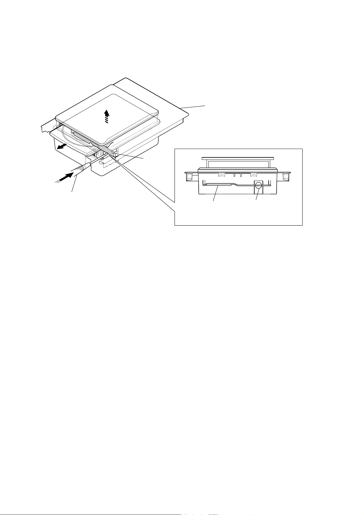
HOW TO OPEN THE TRAY WHEN POWER SWITCH TURN OFF
(HCD-EC79i: UK, Australian/EC99i only)
Note: Please take out the top panel block from a set refer to DISASSEMBLY (from Page 15).
bracket
top panel block
Push hard the bracket by
the flat-head screwdriver.
bracket
– top panel block (front view) –
flat-head screwdriver
6

SECTION 2
GENERAL
HCD-EC69i/EC79i/EC99i
This section is extracted
from instruction manual.
HCD-EC99i
HCD-EC79i (Australian and UK models only)
*
* HCD-EC99i only
Getting Started
FM lead antenna (Extend it horizontally.)
AM loop antenna
To right speaker (High freq.)
To right speaker (Low freq.)
To wall outlet
Solid (Gray/)
Solid (Black/)
HCD-EC79i (North American model only)
HCD-EC69i
*
* HCD-EC79i only
HCD-EC69i only
* HCD-EC99i only
To subwoofer
Solid (Blue/)
Solid (Black/)
To left speaker (High freq.)
Solid (Red/)
Solid (Black/)
To left speaker (Low freq.)
Remote
*
Antennas
Find a location and an orientation that provide good
reception, and then set up the antenna.
Keep the antennas away from the speaker cords and the
power cord to avoid picking up noise.
Subwoofer (HCD-EC99i only)
Insert only the stripped portion of the cord.
Place the subwoofer vertically to obtain a better bass
reproduction. Also, position the subwoofer:
on a solid oor where resonance is unlikely to occur.
at least a few centimeters away from the wall.
away from the center of the room or place a
bookshelf against a wall, to avoid generating a
standing wave.
Speakers
Insert only the stripped portion of the cord.
Power
Connect the power cord to a wall outlet.
If the plug does not t the wall outlet, detach the supplied
plug adaptor (only for models equipped with an adaptor).
To attach the speaker pads
Attach the supplied speaker pads to the bottom of the
front speakers and subwoofer to prevent slipping.
Front speakers:
4 pads for each speaker
Subwoofer:
4 pads (HCD-EC99i only)
is manual mainly explains operations using the
remote, but the same operations can also be performed
using the buttons on the unit having the same or similar
names.
To use the remote
Slide and remove the battery compartment lid, and
insert the two R6 (size AA) batteries (supplied, except
for HCD-EC69i), side rst, matching the polarities
shown below.
Notes on using the remote
With normal use, the batteries should last for about six months.
Do not mix an old battery with a new one or mix dierent types of
batteries.
If you do not use the remote for a long period of time, remove the
batteries to avoid damage from battery leakage and corrosion.
Batteries installed devices shall not be exposed to excessive heat such
as sunshine, re or the like.
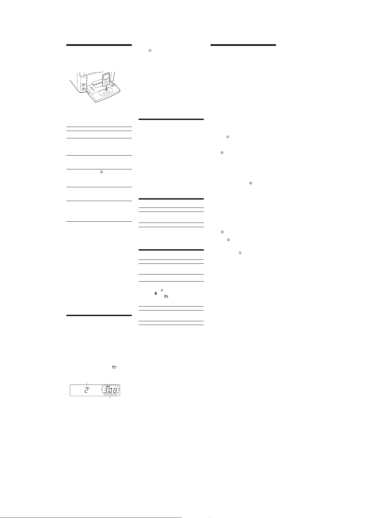
To use the iPod
Make sure the iPod indicator lights up (except for
HCD-EC69i).
Press PUSH
slide the LOCK lever to the HOLD position, and insert
an iPod Dock Adapter into the Dock before use.
For details on the iPod Dock Adapters, refer to the
instructions supplied with the Dock Adapters.
Notes
e iPod Dock Adapter is not supplied with the system.
You can use the iPod only when the iPod indicator
To adjust the volume
Press VOLUME +/ (or turn the VOLUME control on
the unit)
To connect an optional headphones
Connect headphones to the PHONES jack on the
unit.
To set the clock
Use buttons on the remote to set the clock.
1 Press (on/standby)
2 Press TIMER MENU
3 Press /
4 Use the same procedure to set the minutes.
Note
e clock settings are lost when you disconnect the power cord or if a
power failure occurs.
To display the clock when the system is o
Press DISPLAY . e clock is displayed for about
8seconds.
on the unit to ip-open the iPod Dock,
LOCK lever
(except for HCD-EC69i).
.
If “PLAY SET” ashes, press /
select “CLOCK,” and then press
press
to select the clock set mode.
repeatedly to set the hour, and then
.
iPod Dock Adapter
To remove the iPod
Dock Adapter, pull it
up with your ngernail
or a at object using
the slot inside the
adapter.
iPod Connector
lights up
to turn on the system.
repeatedly to
(enter) .
Operations
Playing a CD/MP3 disc
1 Select the CD function.
Press FUNCTION +/
the unit).
2 Place a disc.
HCD-EC99i
HCD-EC79i (Australian and UK models only)
Press (open/close) on the unit, and place a disc
with the label side up on the disc tray.
To close the disc tray, press
Do not force the disc tray closed with your nger, as
this may damage the unit.
HCD-EC79i (North American model only)
HCD-EC69i
Press PUSH OPEN/CLOSE on the unit,
and place a disc with the label side up on the CD
compartment.
To close the CD compartment, press PUSH OPEN/
CLOSE
3 Start playback.
Press (play) (or (play/pause) on the unit)
.
on the unit.
repeatedly (or CD on
on the unit.
(open/close)
PUSH OPEN/CLOSE
To Press
Pause playb ack
Stop playback
Select a folder on an
MP3 disc
Select a track or le
Find a point in a
track or le
Select Repeat Play
To change the play mode
Press PLAY MODE repeatedly while the player is
stopped. You can select normal play (“
les in the folder on the disc), shue play (“SHUF”
or “
(“PGM”).
* When playing a CD-DA (audio) disc, (SHUF) Play performs the
same operation as normal (SHUF) Play.
Note on the CD compartment (HCD-EC79i (North American
model only) and HCD-EC69i)
Do not open the CD compartment when “READING” appears or
during playback, as this may cause a malfunction.
Notes on Repeat Play
All tracks or les on a disc are played repeatedly up to ve times.
“REP1” indicates that a single track or le is repeated until you stop
it.
Note on shue play mode
When you turn o the system, the selected shue play mode (“SHUF”
or “
mode (“
Notes on playing MP3 discs
Do not save other types of tracks or les or unnecessary folders on a
disc that has MP3 les.
Folders that have no MP3 les are skipped.
MP3 les are played back in the order that they are recorded onto
the disc.
(pause) (or (play/pause)
. To resume play,
on the unit)
press the button again.
.
(stop)
(select folder) + /.
(go back)
forward)
Hold down (rewind)
(fast forward)
and release the button at the
desired point.
REPEAT
“REP” or “REP1” appears.
SHUF*” for folder shue), or program play
SHUF”) is cleared and the play mode returns to normal play
”).
/ (go
.
during playback,
repeatedly until
” for all MP3
/
e system can only play MP3 les that have a le extension of
“.mp3”.
Even when le name has the “.mp3” le extension, if the actual
le diers, playing this le may generate a loud noise which could
damage the speaker system and the system may malfunction.
e maximum number of:
folders is 150 (including the root folder).
MP3 les is 255.
MP3 les and folders that can be contained on a single disc is 300.
folder levels (the tree structure of les) is 8.
Compatibility with all MP3 encoding/writing soware, recording
device, and recording media cannot be guaranteed. Incompatible
MP3 discs may produce noise or interrupted audio or may not play
at all.
Notes on playing multisession discs
If the disc begins with a CD-DA (or MP3) session, it is recognized
as a CD-DA (or MP3) disc, and playback continues until another
session is encountered.
A disc with a mixed CD format is recognized as a CD-DA disc.
Listening to the radio
1 Select “TUNER FM” or “TUNER AM.”
Press FUNCTION +/ (or FUNCTION on the unit)
repeatedly.
2 Perform tuning.
For automatic scanning
Press TUNING MODE repeatedly until “AUTO”
appears, and then press +
/
on the unit). Scanning stops automatically
when a station is tuned in, and “TUNED” and “ST”
(for stereo programs only) appear.
If “TUNED” does not appear and the scanning does
not stop, press
manual tuning (below).
For manual tuning
Press TUNING MODE repeatedly until
“MANUAL” appears, and then press +
TUNING +
in the desired station.
/
to stop scanning, then perform
/
on the unit) repeatedly to tune
(or TUNING +
/
(or
Tip
To reduce static noise on a weak FM stereo station, press FM MODE
repeatedly until “MONO” appears to turn o stereo reception.
Presetting radio stations
Use buttons on the remote to preset stations.
1 Tune in the desired station.
2 Press TUNER MEMORY
memory mode.
3 Press +
preset number.
If another station is already assigned to the selected
preset number, the station is replaced by the new
stations.
4 Press
5 Repeat steps 1 through 4 to store other stations.
You can preset up to 20 FM and 10 AM stations. e
preset stations are retained for about half a day even
if you disconnect the power cord or if a power failure
occurs.
6 To call up a preset radio station, press TUNING
MODE
then press +
desired preset number.
to select the tuner
Preset number
/
repeatedly to select the desired
to store the station.
repeatedly until “PRESET” appears, and
/
repeatedly to select the
7
HCD-EC69i/EC79i/EC99i
Playing the iPod
1 Select the iPod function.
Press FUNCTION +/
the unit).
2 Place the iPod.
3 Start playback.
Press (or on the unit)
To control the iPod
You can control your iPod with the following buttons on
the remote or unit.
To Press
Pause playb ack
Scroll up/down the
iPod menus
Select a track
or chapter of
audiobook/podcast
Choose the selected
item
Find a point in a
track or chapter of
audiobook/podcast
Return to the
previous menu or
select a menu
To use the system as a battery charger
You can use the system as a battery charger for the iPod
when the system is on.
e charging begins when the iPod is placed on the
iPod connector. e charging status appears in the iPod
display. For details, see the user’s guide of your iPod.
To stop charging the iPod
Remove the iPod.
Notes
When placing or removing the iPod, handle the iPod in the same
angle as that of the iPod connector on the unit and do not twist or
sway the iPod to prevent connector damage.
Do not carry the unit with an iPod set on the connector. Doing so
may cause a malfunction.
When placing or removing the iPod, brace the unit with one hand
and take care not to press the controls of the iPod by mistake.
Before disconnecting the iPod, pause playback.
While playing video, you cannot use
rewind (fast forward) by holding down
To change the volume level, use VOLUME +/ (or VOLUME
control on the unit)
adjusted on the iPod.
is system is designed for iPod only. You cannot connect any other
portable audio players.
To use an iPod, refer to the user’s guide of your iPod.
Sony cannot accept responsibility in the event that data recorded to
iPod is lost or damaged when using an iPod with this unit.
repeatedly (or iPod on
.
(pause) (or (play/pause)
on the unit)
or (stop) .
. You can scroll up or
/
down the iPod menus much like
the Click Wheel operations of
the iPod or the drag up-or-down
operations of the iPod touch.
(go back)
forward)
or fast-rewind, hold down the
button.
choose the selected item much
like the center button on the iPod
or the touch operation of the
iPod touch.
Hold down (rewind)
playback, and release the button
at the desired point.
(return)
previous menu or select a menu
much like the Menu button on
the iPod or the touch operation
of the iPod touch.
. e volume level does not change even if
/ (go
. To fast-forward
/ (enter) . You can
/ (fast forward) during
/TOOL MENU /
. You can return to the
/
. You can fast
/
.
Creating your own program
(Program Play)
Use buttons on the remote to create your own program.
1 Select the CD function.
Press FUNCTION +/
2 Select the play mode.
Press PLAY MODE
appears while the player is stopped.
3 Select the desired track or le number.
Press
track or le number appears.
When programming MP3 les, press
repeatedly to select the desired folder, and then select
the desired le.
Selected track or le number
repeatedly until “PGM”
/
repeatedly until the desired
repeatedly.
Total playing time of the
selected track or le
+ /
4 Program the selected track or le.
to enter the selected track or le.
Press
5 Repeat steps 3 through 4 to program additional
tracks or les, up to a total of 25 tracks or les.
6 To play your program of tracks or les, press
e program remains available until you open the disc
tray or CD compartment (HCD-EC69i only). To play
the same program again, select the CD function, and
then press
To cancel Program Play
Press PLAY MODE repeatedly until “PGM”
disappears while the player is stopped.
To delete the last track or le of the program
Press CLEAR while the player is stopped.
To view program information, such as total
track number of the program
Press DISPLAY repeatedly.
.
Using optional audio components
(except for HCD-EC69i)
1 Prepare the sound source.
Connect additional audio component to the PC IN
on the unit using an audio analog cord (not
jack
supplied).
2 Turn down the volume.
Press VOLUME (or turn the VOLUME control on
.
the unit)
3 Select the PC function.
Press FUNCTION +/ (or FUNCTION on the unit)
repeatedly.
4 Start playback.
Start playback of the connected component.
5 Adjust the volume.
Press VOLUME +/ (or turn the VOLUME control
.
on the unit)
Adjusting the sound
To Pre s s
Generate a more dynamic
sound (Dynamic Sound
Generator X-tra)
Set the sound eect
To turn on the subwoofer (HCD-EC99i only)
Press SUBWOOFER ON/OFF on the unit until
“SUBWOOFER” appears. e volume of the subwoofer is
linked to the front speakers.
DSGX
EQ
on the unit.
.
Changing the display
To Pre s s
Change
information on the
display*
Change Display
mode (See below.)
* For example, you can view CD/MP3 disc information, such as;
track or le number during normal play.
track or le name (“
artist name (“
album or folder name (“
total playing time while the player is stopped.
e system oers the following display modes.
Display mode When the system is o,
Power Saving
1)
Mode
2)
Clock
1)
You cannot set the clock in Power Saving Mode.
2)
e clock display automatically turns to Power Saving Mode aer
8 seconds.
Notes on the display information
Characters that cannot be displayed appear as “_”.
e following are not displayed;
total playing time for an MP3 disc.
remaining playing time for an MP3 le.
e following are not displayed correctly;
elapsed playing time of an MP3 le encoded using VBR (variable
bit rate).
folder and le names that do not follow either the ISO9660
Level 1, Level 2 or Joliet in the expansion format.
e following are displayed;
total playing time for a CD-DA disc during normal play.
remaining playing time for a track.
ID3 tag information for MP3 les when ID3 version 1 and
version 2 tags are used (ID3 version 2 tag information display has
priority when both ID3 version 1 and version 2 tags are used for a
single MP3 le).
u
p to 15 characters of ID3 tag information using uppercase letters
(A to Z), numbers (0 to 9), and symbols (˝ $ % ’ ( ) * , – . / < = > @
[ \ ] _ ` { | } ! ? ^).
repeatedly when the
DISPLAY
system is turned on.
repeatedly when the
DISPLAY
system is turned o.
”) during normal play.
”) during normal play.
”) during normal play.
e display is turned o to conserve
power. e timer and clock continue
to operate.
e clock is displayed.
Using the timers
e system oers two timer functions. If you use both
timers, the Sleep Timer has priority.
Use buttons on the remote to use the timer functions.
.
Sleep Timer:
You can fall asleep to music. is function works even if
the clock is not set.
repeatedly. If you select “AUTO,” the
Press SLEEP
system automatically turns o aer the current disc stops
or in 100 minutes.
Play Timer:
You can wake up to CD, tuner or iPod at a preset time.
Make sure you have set the clock.
1 Prepare the sound source.
Prepare the sound source, and then press VOLUME
to adjust the volume.
+/
To start from a specic CD track or audio le, create
your own program.
2 Select the timer set mode.
Press TIMER MENU
3 Set the play timer.
Press /
then press
“ON TIME” appears, and the hour indication ashes.
4 Set the time to start playback.
Press /
press
procedure above to set the minutes.
“OFF TIME” appears and the hour indication ashes
in the display.
5 Use the same procedure as in step 4 to set the time
to stop playback.
6 Select the sound source.
Press /
source appears, and then press
shows the timer settings.
7 Turn o the system.
Press
e system turns on 15 seconds before the preset time.
If the system is on at the preset time, the Play Timer
will not play.
Do not operate the system from the time the system
turns on until the play starts.
To check the setting
1 Press TIMER MENU
“SELECT” ashes in the display.
2 Press
3 Press
then press
To cancel the timer
Repeat the same procedure as above until “OFF” appears
in step 3, and then press
To change the setting
Start over from step 1.
Notes for the iPod user
Make sure the iPod is not playing when using the Play Timer.
e Play Timer may not be activated depending on the status of the
connected iPod.
Tip
e Play Timer setting remains as long as the setting is not cancelled
manually.
.
repeatedly to select “PLAY SET,” and
.
repeatedly to set the hour, and then
. e minute indication ashes. Use the
repeatedly until the desired sound
.
.
repeatedly to select “PLAY SEL,” and
/
.
.
.
. e display
8
DISASSEMBLY
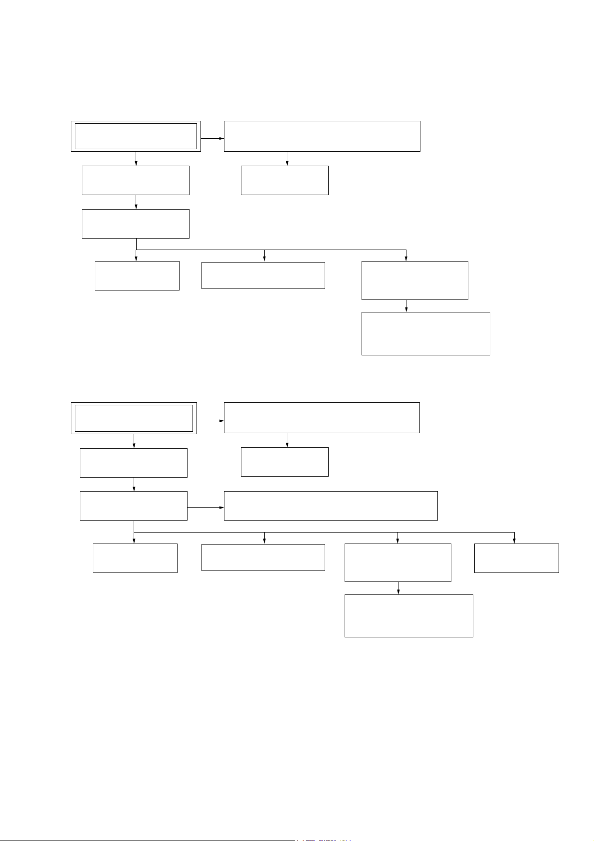
• This set can be disassembled in the order shown below.
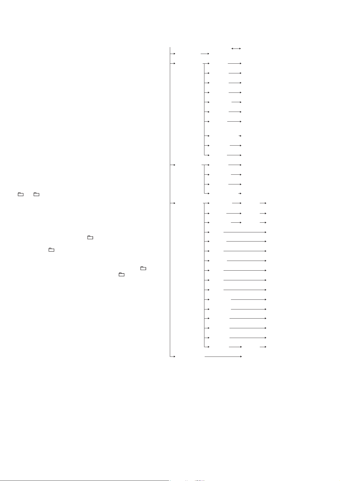
3-1. DISASSEMBLY FLOW
• HCD-EC69i/EC79i: US, Canadian
HCD-EC69i/EC79i/EC99i
SECTION 3
SET
3-2. SIDE PANEL (L)/(R)
(Page 10)
3-3. TOP PANEL BLOCK
(Page 10)
3-6. MAIN BOARD
(Page 12)
3-7 FRONT PANEL BLOCK
(Page 13)
• HCD-EC79i: UK, Australian/EC99i
SET
3-4 ORNAMENT PLATE (DOCK) OR iPod ASSY
(Page 11)
3-5 BASE (DOCK)
(Page 12)
3-8. BASE UNIT
(BU-K8BD90-WOD)
(Page 13)
3-9. OPTICAL PICK-UP BLOCK
(KSM-213CDP/C2NP)
(Page 14)
3-4 ORNAMENT PLATE (DOCK) OR iPod ASSY
(Page 11)
3-10. SIDE PANEL (L)/(R)
(Page 14)
3-11. TOP PANEL BLOCK
(Page 15)
3-13. MAIN BOARD
(Page 16)
3-5 BASE (DOCK)
(Page 12)
3-12. CD MECHANISM DECK (CDM76A-K6BD90-WOD)
(Page 15)
3-14. FRONT PANEL BLOCK
(Page 16)
3-15. BASE UNIT
(BU-K6BD90-WOD)
(Page 17)
3-16. OPTICAL PICK-UP BLOCK
(KSM-213DCP/C2RP)
(Page 17)
3-17. BELT (CDM76)
(Page 18)
9
HCD-EC69i/EC79i/EC99i
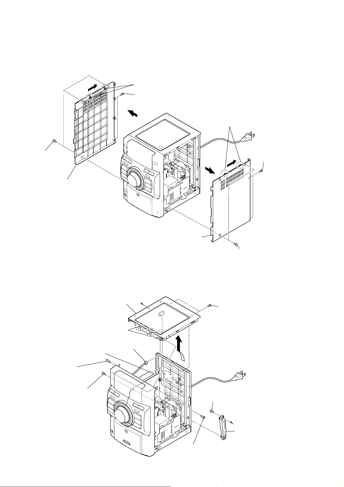
Note: Follow the disassembly procedure in the numerical order given.
3-2. SIDE PANEL (L)/(R) (HCD-EC69i/EC79i: US, Canadian)
two claws
3
two screws
2
(BVTP3 u 10)
three screws
1
(case3 TP2)
side panel (L)
5
3-3. TOP PANEL BLOCK (HCD-EC69i/EC79i: US, Canadian)
4
side panel (R)
5
4
two claws
3
1
(case3 TP2)
2
(BVTP3 u 10)
three screws
two screws
flexible flat cable (21 core)
(CN201)
screw
(KTP3 × 10)
screw
(BVTP3 × 10)
top panel block
R
two claws
connector
(SW750)
screw
(KTP3 × 10)
two screws
(BVTP3 × 10)
screw
(BVTP3 × 10)
bracket (PWB)
10

3-4. ORNAMENT PLATE (DOCK) OR iPod ASSY
Note: This illustration sees the front panel from bottom side.
four claws
Push the gap by
the flat-head screwdriver.
Note: Avoid a claw and put a
flat-head screwdriver in.
"
HCD-EC69i/EC79i/EC99i
Press the iPod dock in the direction of arrow ".
Push in flat-head screwdriver.
Note: Avoid a claw and put a
flat-head screwdriver in.
Open the iPod dock.
ornament plate (dock) or iPod assy
Turn up a ornament plate (dock) or
iPod assy lowpart and remove it without
using by the flat-head screwdriver.
claw
claw
three claws
Push in flat-head screwdriver.
Note: Avoid a claw and put a
flat-head screwdriver in.
11
HCD-EC69i/EC79i/EC99i
3-5. BASE (DOCK)
Note: This illustration sees the front panel from bottom side.
Left up the IP board.
boss
two screws
(B2.6)
base (dock)
boss
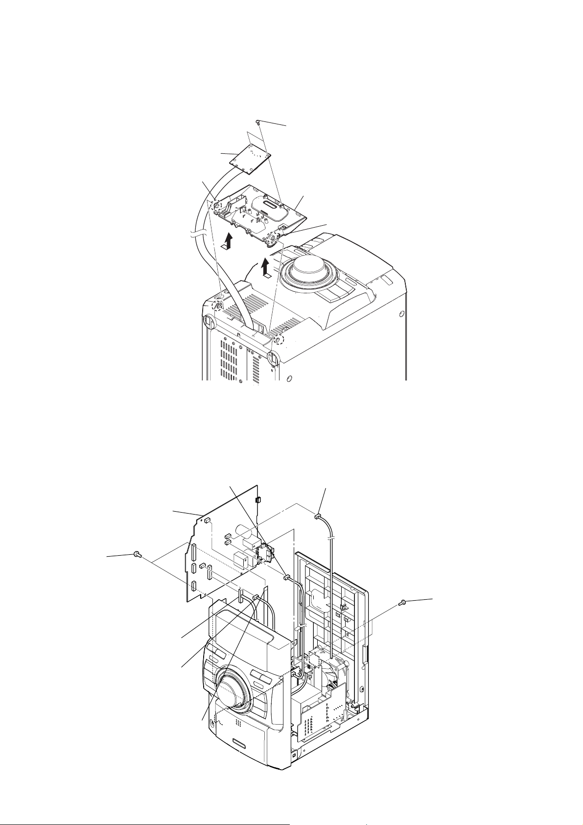
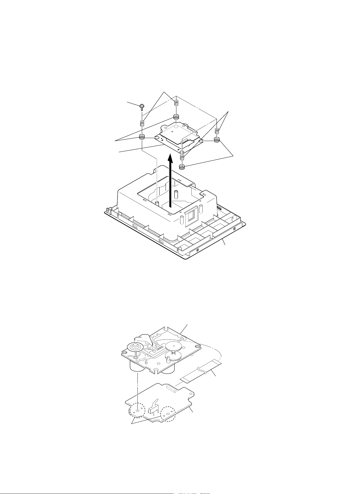
3-6. MAIN BOARD (HCD-EC69i/EC79i: US, Canadian)
connector
(EC69i: CN102, EC79i: CN101)
MAIN board
two screws
(BVTP3 × 10)
connector
(CN504)
connector
(CN609)
fan motor connector
(CN601)
two screws
(BVTP3 × 10)
12
flexible flat cable (5 core)
(CN603)
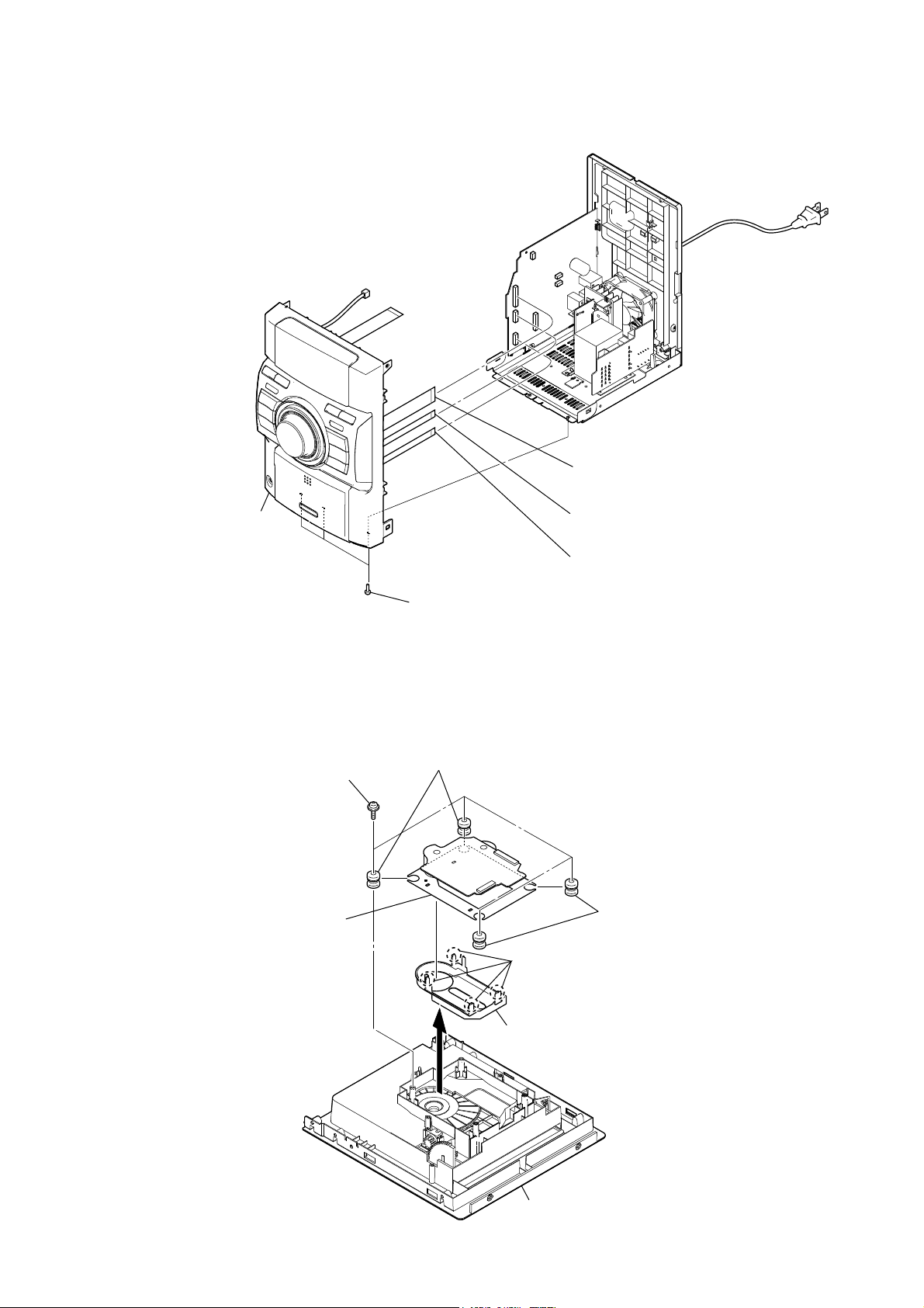
3-7. FRONT PANEL BLOCK (HCD-EC69i/EC79i: US, Canadian)
HCD-EC69i/EC79i/EC99i
flexible flat cable (25 core)
1
(CN607)
front panel block
5
three screws
4
(BVTP3 u 10)
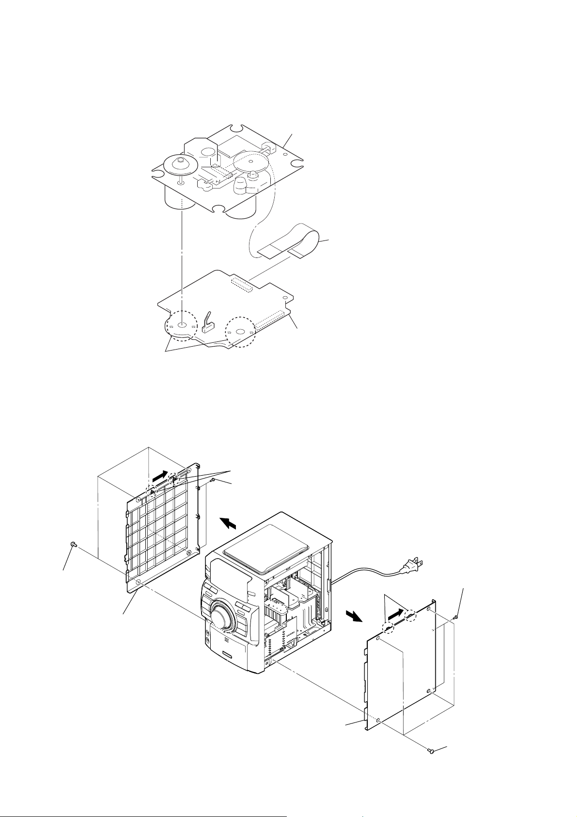
3-8. BASE UNIT BLOCK (BU-K8BD90-WOD) (HCD-EC69i/EC79i: US, Canadian)
Note: This illustration sees the base unit from CD board side.
four screws
(PWH B2.6)
base unit
(BU-K8BD90-WOD)
(green)
2
(CN653)
3
(EC69i: CN606),
flexible flat cable (9 core)
(EC79i (US, Canadian): CN605)
two vibration proof rubbers
four claws
flexible flat cable (11 core)
flexible flat cable (7 core)
two vibration proof rubbers
(red)
CD cover
top panel block
(bottom view)
13
HCD-EC69i/EC79i/EC99i
3-9. OPTICAL PICK-UP BLOCK (KSM-213CDP) (HCD-EC69i/EC79i: US, Canadian)
optical pick-up block
(KSM-213CDP)
wire (flat type) (16 core)
(optical pick-up, CD board: CN201)
Remove the four solders.
3-10. SIDE PANEL (L)/(R) (HCD-EC79i: UK, Australian/EC99i)
four screws
1
(case3 TP2)
two claws
3
two screws
2
(BVTP3 u 10)
4
CD board
two claws
3
two screws
2
(BVTP3 u 10)
14
side panel (L)
5
side panel (R)
5
4
four screws
1
(case3 TP2)
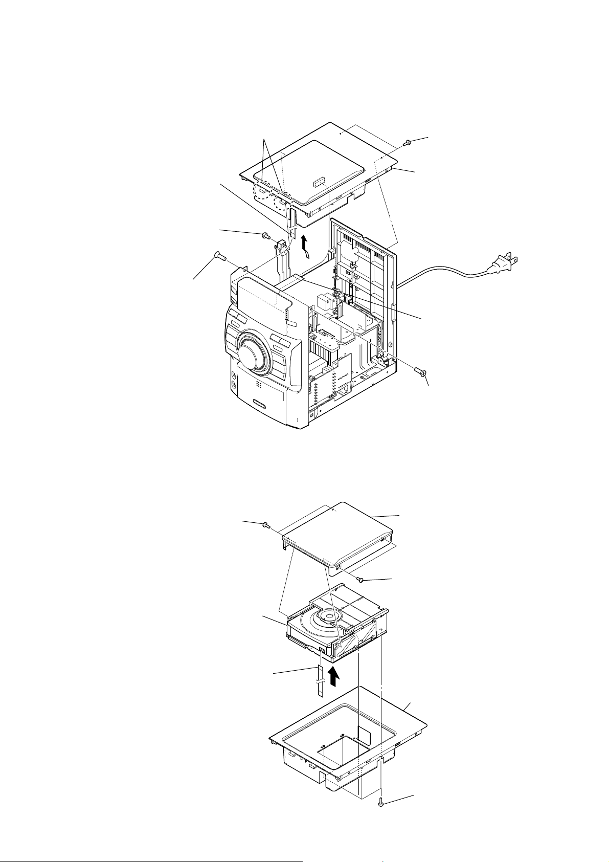
3-11. TOP PANEL BLOCK (HCD-EC79i: UK, Australian/EC99i)
two claws
flexible flat cable (5 core)
(CN302)
screw
(BVTP3 × 10)
screw
(KTP3 × 10)
HCD-EC69i/EC79i/EC99i
two screws
(BVTP3 × 10)
top panel block
flexible flat cable (21 core)
(CN201)
3-12. CD MECHANISM DECK (CDM76A-K6BD90-WOD) (HCD-EC79i: UK, Australian/EC99i)
two screws
(B2.6)
CD mechanism deck block
(CDM76A-K6BD90-WOD)
flexible flat cable (5 core)
top lid
two screws
(B2.6)
screw
(KTP3 × 10)
top panel (loading)
four screws
(BVTP3 × 10)
15
HCD-EC69i/EC79i/EC99i
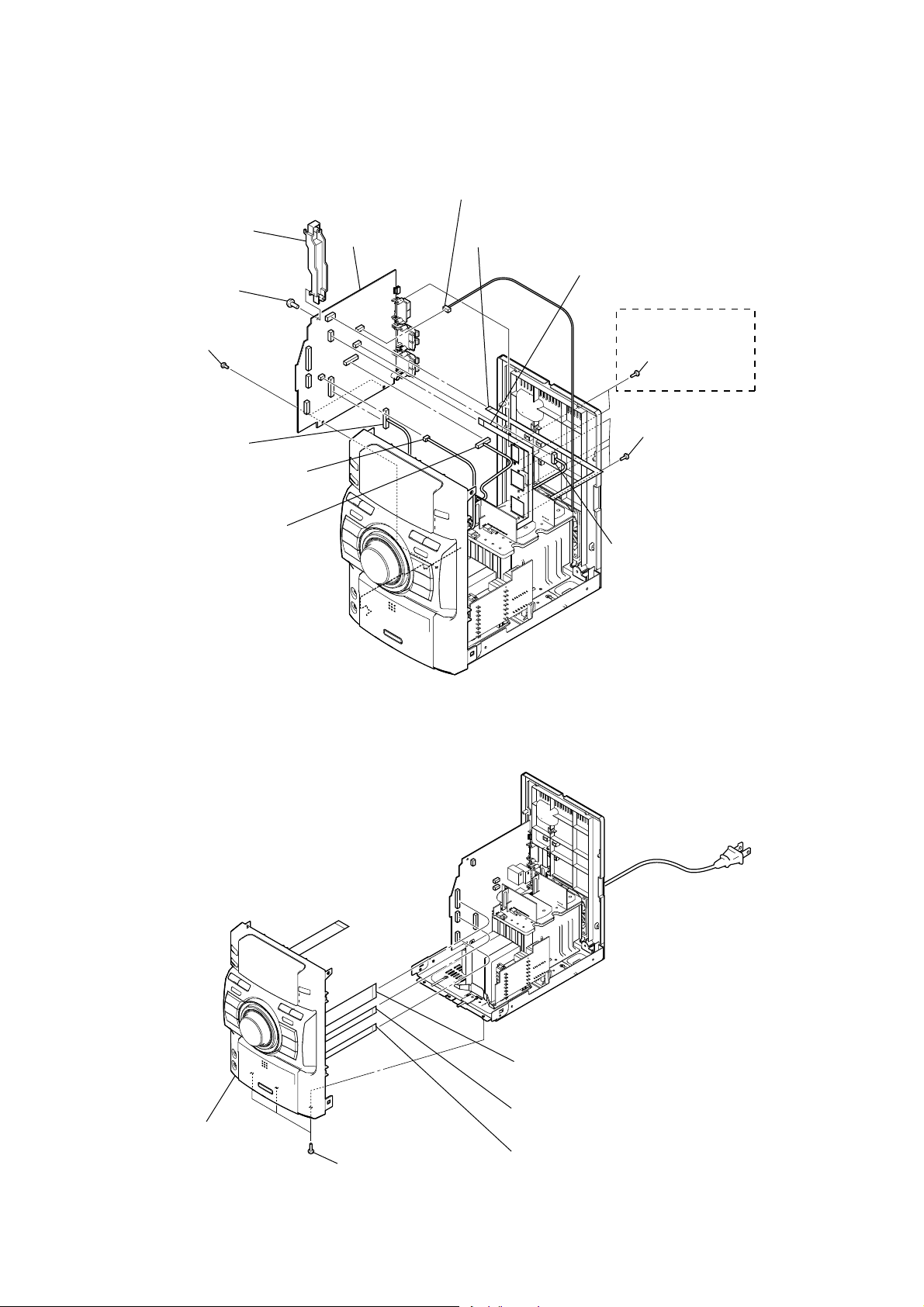
3-13. MAIN BOARD (HCD-EC79i: UK, Australian/EC99i)
bracket (PWB)
RB
screw
R
(BVTP3 × 10)
MAIN board
RT
fan motor connector
(CN601)
flexible flat cable (5 core)
(CN603)
flexible flat cable (7 core)
(EC99i: CN643)
two screws
(BVTP3 × 10)
connector
(EC79i: CN704,
EC99i: CN654)
connector
(CN609)
connector
(EC79i: CN101,
EC99i: CN205)
3-14. FRONT PANEL BLOCK (HCD-EC79i: UK, Australian/EC99i)
(EC99i)
two screws
(BVTP3 × 10)
four screws
(BVTP3 × 10)
connector
(EC99i: CN102)
16
front panel block
three screws
(BVTP3 × 10)
flexible flat cable (25 core)
(CN607)
flexible flat cable (11 core)
(CN653)
flexible flat cable (9 core)
(CN605)
3-15. BASE UNIT (BU-K6BD90-WOD) (HCD-EC79i: UK, Australian/EC99i)
Note: This illustration sees the base unit from CD board side.
two coil springs (insulator)
four screws
(PTPWH M2.6)
two insulators
base unit
(BU-K6BD90-WOD)
HCD-EC69i/EC79i/EC99i
two coil springs (insulator)
two insulators
3-16. OPTICAL PICK-UP BLOCK (KSM-213DCP) (HCD-EC79i: UK, Australian/EC99i)
top panel block
(bottom view)
optical pick-up block
(KSM-213DCP)
flexible flat cable (16 core)
(optical pick-up, CD board: CN201)
CD board
Remove the four solders.
17
HCD-EC69i/EC79i/EC99i
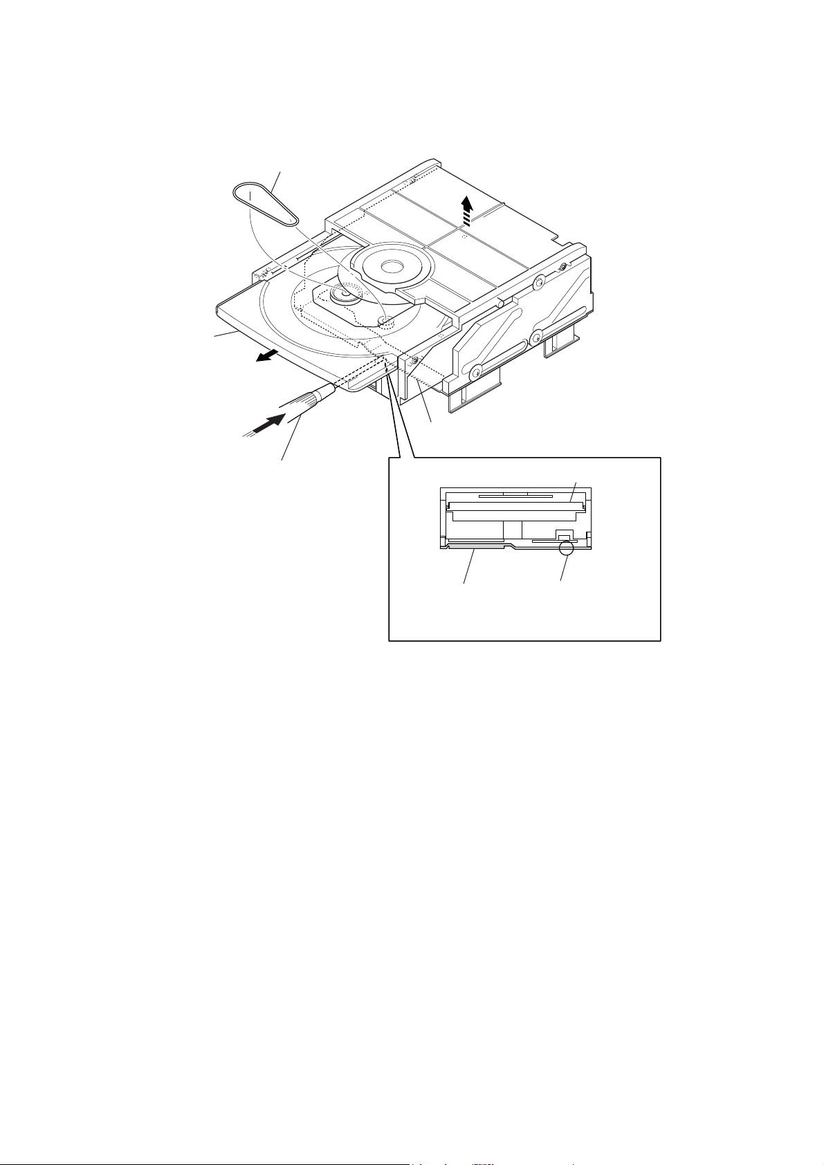
3-17. BELT (CDM76) (HCD-EC79i: UK, Australian/EC99i)
belt (CDM76)
Draw out the tray.
bracket
Push hard the bracket by
the flat-head screwdriver.
tray
bracket
– CD mechanism deck (front view) –
flat-head screwdriver
18

SECTION 4
TEST MODE
HCD-EC69i/EC79i/EC99i
Ver. 1.1
COLD RESET
The cold reset clears all data including preset data stored in the
memory to initial conditions. Execute this mode when returning
the set to the customer.
Procedure:
1. In the standby status, press the [
] button to turn the power
?/1
on.
2. Press three buttons of [
], [CD] and [
x
] simultaneously.
?/1
3. When “RESET” appears, the set enters standby status.
PANEL TEST MODE
Enter The Panel Test Mode
Procedure:
1. In the standby status, press the [
] button to turn the power
?/1
on.
2. Press three buttons of [
], [iPod] and [
x
] simultaneously
?/1
(EC69i/EC79i: US, Canadian models).
Press three buttons of [DISPLAY], [
] and [iPod] simultane-
x
ously (EC79i: UK, Australian/EC99i).
3. When the panel test mode is activated, LEDs and segments of
the liquid crystal display are all turned on.
Version Check
Procedure:
1. In the panel test mode (all LEDs and segments of the liquid
crystal display are turned on), press the [FUNCTION] button.
2. On the liquid crystal display, date and version are displayed
“xxxxxxxx”.
3. From this status, press the [u] button, and the destination and
model name are displayed.
4. To release from this mode, press three button of [
[
] simultaneously (EC69i/EC79i: US, Canadian models).
?/1
], [iPod] and
x
To release from this mode, press three buttons of [DISPLAY],
[
] and [iPod] simultaneously (EC79i: UK, Australian/
x
EC99i).
Key Test Mode
Procedure:
1. In the panel test mode (all LEDs and segments of the liquid
crystal display are turned on), press the [
] button.
x
2. The message “KEY0 0 0”displayed. Whenever any buttons
are pressed and the [VOLUME] dial is turned, the value is
changed.
3. To release from this mode, press three button of [x], [iPod] and
[
] simultaneously (EC69i/EC79i: US, Canadian models).
?/1
To release from this mode, press three buttons of [DISPLAY],
[x] and [iPod] simultaneously (EC79i: UK, Australian/
EC99i).
CD TRAY LOCK (EC79i: UK, Australian/EC99i)
This mode is for the antitheft of CD disc in shop. (not for transport)
Procedure:
1. Press the [
] button to turn the power on.
?/1
2. Press the [FUNCTION] button to select CD function.
3. Insert a disc.
4. While pressing the [x] button, press the [Z] button for more 5
seconds.
5. The message “LOCKED” is displayed and the disc tray is
locked. (Even if exiting from this mode, the disc tray is still
locked)
6. If press the [Z] button to eject the disc, the message “LOCKED”
is displayed and can not eject the disc.
7. To release this lock, while pressing the [
] button for 5 seconds again.
[
Z
] button, press the
x
8. The message “UNLOCKED” is displayed and the disc tray is
unlocked.
CD POWER MANAGE
This mode is for switch the CD power supply on/off. Even if this
state pulls out AC plug, it is held.
Procedure:
1. Press the [
] button to turn the power on.
?/1
2. Press the [FUNCTION] button to select CD function.
3. Press the [
] button again to turn the power off (standby).
?/1
4. After pressing the [DISPLAY] button on the remote commander, while pressing the [x] button, press the [
?/1
] button.
5. It turns power on and display “CD POWER”, then display
“ON” or “OFF”.
CHANGE-OVER THE AM TUNING INTERVAL
(EC69i: US, Canadian, Australian/EC79i: US, Canadian,
Australian/EC99i: US, Canadian and Australian models)
The AM tuning interval can be changed over 9 kHz or 10 kHz.
Procedure:
1. Press the [
] button to turn the power on.
?/1
2. Press the [FUNCTION] button to select TUNER (AM) function.
3. Press the [
] button again to turn the power off (standby).
?/1
4. After pressing the [DISPLAY] button on the remote commander, while pressing the [TUNING +
press the [
?/1
] button.
M L
] button,
5. It turns power on and display “9k STEP” or “10k STEP”, and
thus the tuning interval is changed over.
CD REPEAT 5 LIMIT CANCEL MODE
Number of repeats for CD playback is 5 times when the repeat
mode is “REPEAT”. This mode enables CD to repeat playback for
limitless times.
Procedure:
1. Press the [
] button to turn the power on.
?/1
2. Press the [FUNCTION] button to select CD function.
3. Press three buttons of [
], [TUNING +
x
M L
] and [
?/1
simultaneously (EC69i/EC79i: US, Canadian models).
Press three buttons of [DISPLAY], [x] and [TUNING +
L
] simultaneously (EC79i: UK, Australian/EC99i).
M
4. It enters the CD repeat 5 limit cancel mode and displays “NO
LIMIT”.
5. To release this mode, press the [
] button to turn the power off.
?/1
]
19
HCD-EC69i/EC79i/EC99i
CD SERVO TEST MODE
This mode can check the servo system operations of the optical
pick-up system (= optical unit + CD board).
Note 1: Do not enter the this mode while any other test mode is in prog-
Note 2: Do not enter any other test mode while the this mode is in prog-
ress.
ress.
How to Enter the CD Servo Test Mode
Procedure:
1. Press the [
] button to turn the power on.
?/1
2. Press the [FUNCTION] button to select CD function.
3. Press three buttons of [
] simultaneously.
[
?/1
u
], [TUNING + M L] and
4. It enters the CD servo test mode and displays “BDT S CU”.
How to Exit from the CD Servo Test Mode
Procedure:
1. Press three buttons of [u], [TUNING + M L] and
[
] simultaneously.
?/1
2. It releases from the CD Servo Test Mode and returns to the
ordinary CD function.
Key Operation:
[ +], [ –]:
Use these keys to move between the fi ve modes
contained in the CD Servo Test Mode, that are the
S-Curve Mode, the RAM Read Mode, the RAM
Write Mode, the Command Out Mode and the Error
Rate Mode as described below. Also, use these keys
to move between the menus within the respective
fi ve modes. When [ +] is pressed, the screen advances to the next menu or to the next mode. When
[ –] is pressed, the screen returns back to the
previous menu or to the previous mode. Use these
keys also to increase or decrease the numeric value
when changing the numeric value. Pressing [ +]
increases the value and pressing [ –] decreases
the value.
[DSGX], [iPod]:
Use these keys to move between the different layers
of the hierarchy of the CD Servo Test Mode shown
below. Press [DSGX] to move down to the lower
layer, and press [iPod] to move up to the higher
layer.
[TUNING +
M L
], [– TUNING
l m
]:
Use these keys to move the cursor to the right digit
or to the left digit in the six-digit number, when
changing the numeric value.
Press [TUNING +
to the right, and press [– TUNING
M L
] to move the cursor
l m
] to
return the cursor to the left.
CD Servo Test Mode Tree:
S Curve Mode LD ON
(BDT S CU) (LD ON)
RAM Read Mode
(BDTRAM R) (DISCTYPE) (AL: 0000, RW: 0001)
Gain Index value indication
(GAININDX) (0001)
RFO GAIN value indication
(RFO_GAIN) (0009)
FEO GAIN value indication
(FEO_GAIN) (0005)
SBAD GAIN value indication
(SBAD_GAI) (0007)
TEO GAIN value indication
(TEO_GAIN) (000A)
Disc Size value indication
(DISCSIZE) (0000: Non disc, 0001: 8cm,
0002: 12cm)
(OPABRKER) (0000)
SBBT Data value indication
(SBBT DAT) (006C)
FEOOCD value indication
(FEOOCD) (0440)
RAM Write Mode
(BDTRAM W) (00 SPG) (Non mask:00, Mask:01)
Fix RF Gain value edit
(00 FIX) (Non Fix:00, AL Fix:01, RW Fix:02)
TMAX ON value edit
(00 TMA)
Driver Mute OFF value edit
(00 D_M) (Normal:00, Forced OFF:01)
Command Out Mode
(BDT COMO) (COMOUT6X) (000000) (OK)
READ2X value edit command out
(READ2X) (60) (50)
REG READ value edit command out
(REG_READ) (00) (0000)
FEBC? command out
(FEBC?) (00)
FGADD? command out
(FGADD?) (10)
TEBC? command out
(TEBC?) (00)
TGADD? command out
(TGADD?) (00)
RFGC? command out
(RFGC?) (00)
FEOF? command out
(FEOF?) (FFC0)
TEOF? command out
(TEOF?) (FFC0)
TEIOCD1? command out
(TEIOCD1?) (FE80)
TEIOCD2? command out
(TEIOCD2?) (FF40)
TEIOCD3? command out
(TEIOCD3?) (FFC0)
TEOOCD? command out
(TEOOCD?) (FD00)
FEOOCD? command out
(FEOOCD?) (F780)
MONITOR value edit command out
(MONITOR) (570A00) (OK)
Error Rate Mode Error rate indication
(BDT ERR) (00000000)
Higher layer Lower layer of menu hierarchy
Disc Type value indication
Op ABRAKE Error
SPG Mask value edit
COMOUT6X value edit command out
value indication
[FUNCTION]:
Use this key to execute Command Out in the Com-
mand Out Mode.
20

HCD-EC69i/EC79i/EC99i
CD SERVICE MODE
This mode can move the SLED of the optical pick-up, and also can
turn the optical pick-up laser power on and off.
Procedure:
1. Press the [
2. Press three buttons of [u], [ +] and [
3. Press the [FUNCTION] button to select CD function.
4. It enters the CD service mode and displays “SERVICE”.
5. To exit from this mode, press three buttons of [u], [
and [
?/1
Key Operation:
[TUNING +
Use these keys to move the SLED. When [TUN-
When [– TUNING
[DISPLAY]:
Use this key to turn the optical pick-up laser power
CD ERROR CODE
The past errors of the optical pick-up system (= optical unit + CD
board) are displayed as the BD Errors as shown below.
Procedure:
1. Press the [
2. Press the [FUNCTION] button to select CD function.
3. Press three buttons of [x], [DSGX] and [
(EC69i/EC79i: US, Canadian models).
Press three buttons of [ +], [x] and [DISPLAY] simultane-
ously (EC79i: UK, Australian/EC99i).
4. Then, the BD error code is displayed as “D0xxxxxx” (x means
hexadecimal number) on the liquid crystal display as shown
below.
5. Every pressing of the [TUNING +
mode increments the number after “D” starting from “D0”
up to “D9”, and then returns to “D0”. Every pressing of the
[– TUNING
number after “D”. The smaller the error code number is, the
newer the error content is.
6. To release from this mode, press the [
power off.
] button to turn the power on.
?/1
] simultaneously.
?/1
] simultaneously.
M L
?/1
], [– TUNING
M L
ING +
moves to outer circumference and the message
“SLED OUT” is displayed.
mode, the SLED moves to inner circumference and
the message “SLED IN” is displayed.
on and off. When the laser power is turned on, the
message “LD ON” is displayed. When the laser
power is turned off, the message “LD OFF” is displayed.
] button to turn the power on.
l m
] button in this mode decrements the
l m
] is pressed in this mode, the SLED
l m
]:
] is pressed in this
] simultaneously
?/1
M L
] button in this
] button to turn the
?/1
+]
2 It indicates the error content
01: The focus servo cannot lock-in.
02: GFS is no good (NG).
03: The startup time exceeds the specifi ed period of time (time
over)
04: The focus servo is unlocked continuously.
05: Q code cannot be obtained within the specifi ed period of
time.
06: The tracking servo cannot lock-in.
07: Blank disc
3 It indicates the on-going processing of optical pick-up system
(= optical unit + CD board) when the trouble has occurred.
01: The CD SHIP mode processing is in progress.
02: The POWER OFF processing is in progress.
03: The INITIALIZE processing is in progress.
04: The optical pick-up system (= optical unit + CD board) is
in the stop state.
05: The STOP operation is in progress.
06: The startup processing is in progress.
07: The TOC read-in processing is in progress.
08: The SEARCH operation is in progress.
09: The PLAY operation is in progress.
0A: The PAUSE operation is in progress.
0B: The PLAY – MANUAL SEARCH operation is in prog-
ress.
0C: The PAUSE – MANUAL SEARCH operation is in prog-
ress.
4 It indicates the operation that is being processed when the trou-
ble has occurred.
It indicates the step number of each processing specifi ed by 3.
Because the numbers of steps are different in each processing,
this number is different in each processing.
Contents of “BD Errors”
Error display example
D 0 02 09 01
1 2 3 4
1 It indicates the error history number
0 to 9: The error code number 0 indicates the newest error.
21
 Loading...