

Sony HCDDZ-260, HCDDZ-270, HCDDZ-278 Service manual
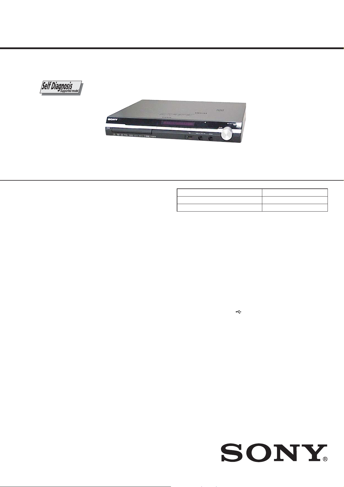
HCD-DZ260/DZ270/HDZ278
SERVICE MANUAL
Ver. 1.2 2008.08
Photo : HCD-DZ270
• HCD-DZ260/DZ270/HDZ278 are the amplifi er, DVD/CD and
tuner section in DAV-DZ260/DZ270/HDZ278.
This system incorporates with Dolby* Digital and Dolby Pro
Logic (II) adaptive matrix surround decoder and the DTS** Digital
Surround System.
* Manufactured under license from Dolby Laboratories.
“Dolby”, “Pro Logic”, and the double-D symbol are trademarks
of Dolby Laboratories.
** Manufactured under license from DTS, Inc.
“DTS” and “DTS Digital Surround” are registered trademarks
of DTS, Inc.
US Model
Canadian Model
HCD-HDZ278
AEP Model
UK Model
HCD-DZ260
E Model
Australian Model
HCD-DZ270
Model Name Using Similar Mechanism HCD-DZ230/DZ231/HDZ235
Mechanism Type CDM85-DVBU102
Optical Pick-up Name KHM-313CAA
SPECIFICATIONS
AUDIO POWER SPECIFICATIONS
for the US model (HDZ278)
POWER OUTPUT AND TOTAL HARMONIC
DISTORTION:
With 3 ohms loads, both
channels driven, from 180
- 20,000 Hz; rated 84 watts
per channel minimum
RMS power, with no more
than 0.7% total harmonic
distortion from 250 milli
watts to rated output.
Amplifi er Section
US models:
Surround mode (reference) RMS output power
FL/FR/C/SL/SR*: 142
watts (per channel at 3
ohms, 1 kHz, 10% THD)
Subwoofer*: 140 watts (at
3 ohms, 80 Hz, 10% THD)
Other models:
Stereo mode (rated) 108 W + 108 W (at 3 ohms,
1 kHz, 1% THD)
Surround mode (reference) RMS output power
FL/FR/C/SL/SR*: 142
watts (per channel at 3
ohms, 1 kHz, 10% THD)
Subwoofer*: 140 watts (at
3 ohms, 80 Hz, 10% THD)
* Depending on the decoding mode settings and the
source, there may be no sound output.
Inputs (Analog) (DZ260)
TV (AUDIO IN) Sensitivity: 450/250 mV
AUDIO IN Sensitivity: 250/125 mV
Inputs (Digital) (DZ260)
TV (COAXIAL IN/OPTICAL IN)
Impedance: 75 ohms/Inputs (Analog) (DZ270/HDZ278)
TV/VIDEO (AUDIO IN) Sensitivity: 450/250 mV
AUDIO IN Sensitivity: 250/125 mV
Inputs (Digital) (HDZ278)
TV/VIDEO (COAXIAL IN/OPTICAL IN)
Impedance: 75 ohms/Outputs (Analog)
Phones Accepts low- and high impedance headphones.
Super Audio CD/DVD System
Laser Semiconductor laser
(Super Audio CD/DVD: λ
= 650 nm)
(CD: λ = 790 nm)
Emission duration:
continuous
Signal format system
North American, Mexican, and Latin American models:
NTSC
Other models: NTSC/PAL
USB Section (DZ260/DZ270)
Supported bit rate
MP3 (MPEG 1 Audio Layer-3):
32 kbps - 320 kbps
WMA: 48 kbps - 192 kbps
AAC: 48 kbps - 320 kbps
Sampling frequencies
MP3 (MPEG 1 Audio Layer-3):
32/44.1/48 kHz
WMA: 44.1 kHz
AAC: 44.1 kHz
(USB) port:
Maximum current: 500 mA
Tuner Section
System PLL quartz-locked digital
synthesizer
FM tuner section
Tuning range
North American models: 87.5 MHz - 108.0 MHz
(100 kHz step)
Other models: 87.5 MHz - 108.0 MHz (50
kHz step)
Antenna (aerial) FM wire antenna (aerial)
Antenna (aerial) terminals 75 ohms, unbalanced
Intermediate frequency 10.7 MHz
– Continued on next page –
DVD RECEIVER
9-887-958-03
2008H04-1
2008.08
©
Sony Corporation
Audio&Video Business Group
Published by Sony Techno Create Corporation
HCD-DZ260/DZ270/HDZ278
Ver. 1.2
AM tuner section
Tuning range
North American, Mexican, and Latin American models:
530 kHz - 1,710 kHz (with
the interval set at 10 kHz)
531 kHz - 1,710 kHz (with
the interval set at 9 kHz)
European, Russian, and Middle Eastern models:
531 kHz - 1,602 kHz (with
the interval set at 9 kHz)
Australian and New Zealand models:
531 kHz - 1,710 kHz (with
the interval set at 9 kHz)
530 kHz - 1,710 kHz (with
the interval set at 10 kHz)
Other models: 531 kHz - 1,602 kHz (with
the interval set at 9 kHz)
530 kHz - 1,610 kHz (with
the interval set at 10 kHz)
Antenna (aerial) AM loop antenna (aerial)
Intermediate frequency 450 kHz
Video Section (DZ260)
Outputs R/G/B: 0.7 Vp-p 75 ohms
HDMI OUT: Type A (19 pin)
Video Section (DZ270/HDZ278)
Outputs VIDEO: 1 Vp-p 75 ohms
COMPONENT:
Y: 1 Vp-p 75 ohms
P
75 ohms
HDMI OUT: Type A (19 pin)
B/CB, PR/CR: 0.7 Vp-p
General
Power requirements
North American models: 120 V AC, 60 Hz
Mexican models: 120 V AC, 60 Hz
Venezuelan models: 120 V AC, 60 Hz
Taiwan models: 120 V AC, 50/60 Hz
Argentine models: 220 V - 240 V AC, 50/60 Hz
Latin American models: 110 V - 240 V AC, 50/60 Hz
Other models: 220 V - 240 V AC, 50/60 Hz
Power consumption
HDZ278: On: 155 W
Standby: 0.3 W (at the
Power Saving mode)
DZ260/DZ270: On: 160 W
Standby: 0.3 W (at the
Power Saving mode)
Output voltage (DIGITAL MEDIA PORT)
(DZ260/HDZ278 only) DC 5 V
Output current (DIGITAL MEDIA PORT)
(DZ260/HDZ278 only) 700 mA
Dimensions (approx.) 430 mm × 66 mm × 385 mm
(17 in × 2
(w/h/d) incl. projecting parts
Mass (approx.) 4.2 kg (9 lb 5 oz)
Design and specifi cations are subject to change without
notice.
5/8 in × 15 1/4 in)
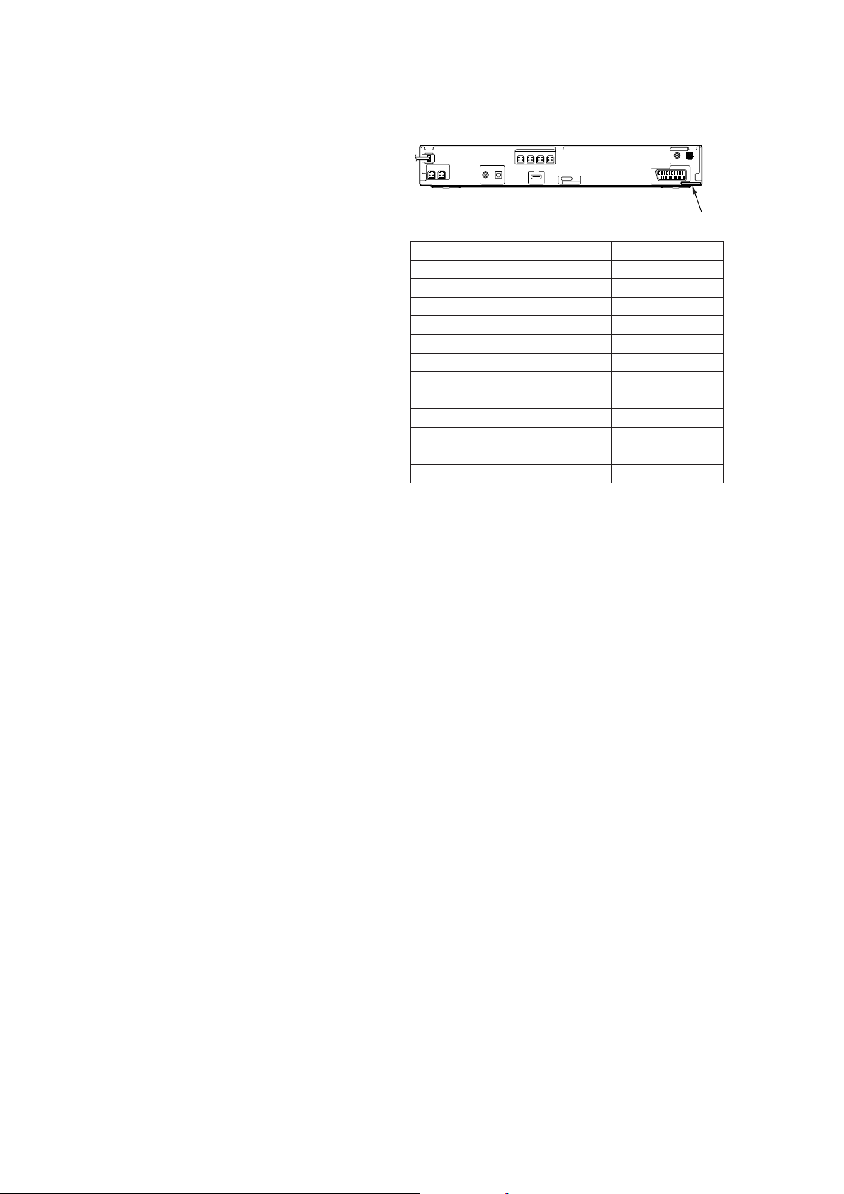
MODEL IDENTIFICATION
– Back Panel –
Model Part No.
DZ260: AEP, UK models
HDZ278: US model
HDZ278: CND model
DZ270: TW model
DZ270: E3 model
DZ270: E32 model
DZ270: MX model
DZ270: E12 model
DZ270: AUS model
DZ270: AR model
DZ270: KR model
DZ270: E87 model
• Abbreviation
AR : Argentina model
AUS : Australian model
CND : Canadian model
E3 : 240 V AC area in E model
E12 : 220-240 V AC area in E model
E32 : 110-240 V AC area in E model
E87 : Venezuelan model
KR : Korea model
MX : Mexican model
TW : Taiwan model
Parts No.
3-273-759-0[]
3-273-759-1[]
3-273-759-2[]
3-273-759-8[]
3-273-760-0[]
3-273-760-1[]
3-273-760-2[]
3-273-760-4[]
3-273-760-5[]
3-273-760-6[]
3-273-760-8[]
3-875-160-2[]
SAFETY-RELATED COMPONET WARNING!
COMPONENTS IDENTIFIED BY MARK 0 OR DOTTED LINE
WITH MARK 0 ON THE SCHEMATIC DIAGRAMS AND IN
THE PARTS LIST ARE CRITICAL TO SAFE OPERATION.
REPLACE THESE COMPONENTS WITH SONY PARTS
WHOSE PART NUMBERS APPEAR AS SHOWN IN THIS
MANUAL OR IN SUPPLEMENTS PUBLISHED BY SONY.
ATTENTION AU COMPOSANT AYANT RAPPORT
À LA SÉCURITÉ!
LES COMPOSANTS IDENTIFIÉS PAR UNE MARQUE 0 SUR
LES DIAGRAMMES SCHÉMATIQUES ET LA LISTE DES
PIÈCES SONT CRITIQUES POUR LA SÉCURITÉ DE FONCTIONNEMENT. NE REMPLACER CES COM- POSANTS QUE
PAR DES PIÈCES SONY DONT LES NUMÉROS SONT DONNÉS DANS CE MANUEL OU DANS LES SUPPLÉMENTS
PUBLIÉS PAR SONY.
2
Special Component Notice
The components identifi ed by mark 9 contain confi dential infor-
mation.
Strictly follow the instructions whenever the components are repaired and/or replaced.
Notice pour composants spéciaux
Les composants identifi és par la marque 9 contiennent des infor-
mations confi dentielles.
Suivre scrupuleusement les instructions chaque fois qu’un composant est remplacé et / ou réparé.
HCD-DZ260/DZ270/HDZ278
SAFETY CHECK-OUT
After correcting the original service problem, perform the following safety check before releasing the set to the customer:
Check the antenna terminals, metal trim, “metallized” knobs,
screws, and all other exposed metal parts for AC leakage.
Check leakage as described below.
LEAKAGE TEST
The AC leakage from any exposed metal part to earth ground and
from all exposed metal parts to any exposed metal part having a
return to chassis, must not exceed 0.5 mA (500 microamperes.).
Leakage current can be measured by any one of three methods.
1. A commercial leakage tester, such as the Simpson 229 or RCA
WT-540A. Follow the manufacturers’ instructions to use these
instruments.
2. A battery-operated AC milliammeter. The Data Precision 245
digital multimeter is suitable for this job.
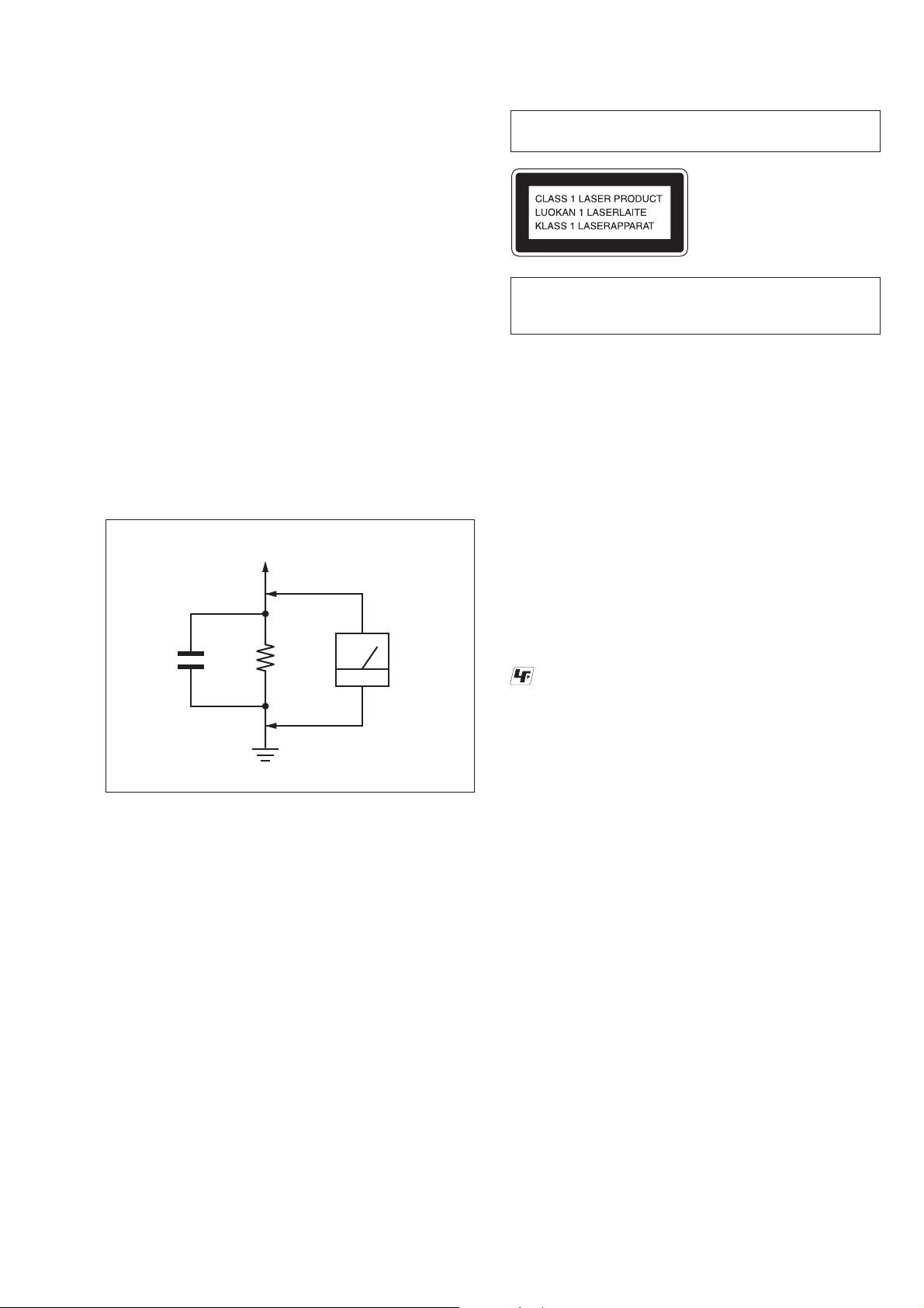
3. Measuring the voltage drop across a resistor by means of a
VOM or battery-operated AC voltmeter . The “limit” indication
is 0.75 V, so analog meters must have an accurate low-voltage
scale. The Simpson 250 and Sanwa SH-63Trd are examples
of a passive VOM that is suitable. Nearly all battery operated
digital multimeters that have a 2 V AC range are suitable. (See
Fig. A)
To Exposed Metal
Parts on Set
Laser component in this product is capable of emitting radiation exceeding the limit for Class 1.
This appliance is classifi ed as a
CLASS 1 LASER product.
This marking is located on the
rear or bottom exterior.
CAUTION
Use of controls or adjustments or performance of procedures other than
those specifi ed herein may result in hazardous radiation exposure.
Notes on chip component replacement
• Never reuse a disconnected chip component.
• Notice that the minus side of a tantalum capacitor may be damaged by heat.
Flexible Circuit Board Repairing
• Keep the temperature of soldering iron around 270 °C during
repairing.
• Do not touch the soldering iron on the same conductor of the
circuit board (within 3 times).
• Be careful not to apply force on the conductor when soldering
or unsoldering.
AC
1.5 kΩ0.15 μF
Earth Ground
voltmeter
(0.75 V)
Fig. A. Using an AC voltmeter to check AC leakage.
UNLEADED SOLDER
Boards requiring use of unleaded solder are printed with the leadfree mark (LF) indicating the solder contains no lead.
(Caution: Some printed circuit boards may not come printed with
the lead free mark due to their particular size)
: LEAD FREE MARK
Unleaded solder has the following characteristics.
• Unleaded solder melts at a temperature about 40 °C higher
than ordinary solder.
Ordinary soldering irons can be used but the iron tip has to be
applied to the solder joint for a slightly longer time.
Soldering irons using a temperature regulator should be set to
about 350 °C.
Caution: The printed pattern (copper foil) may peel away if the
heated tip is applied for too long, so be careful!
• Strong viscosity
Unleaded solder is more viscous (sticky, less prone to fl ow)
than ordinary solder so use caution not to let solder bridges
occur such as on IC pins, etc.
• Usable with ordinary solder
It is best to use only unleaded solder but unleaded solder may
also be added to ordinary solder.
3
HCD-DZ260/DZ270/HDZ278
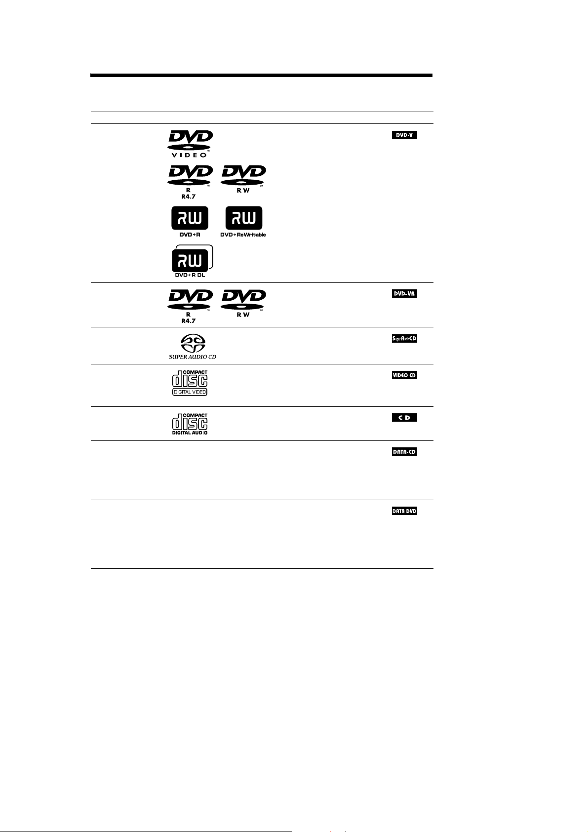
Playable Discs
nocIscitsiretcarahCogolcsiDepyT
OEDIVDVD•OEDIVDVD
• DVD-R/DVD-RW in DVD
VIDEO format or video mode
• DVD+R/DVD+RW in DVD
VIDEO format
VR (Video
Recording)mode
• DVD-R/DVD-RW in VR (Video
Recording) mode (exceptfor
DVD-R DL)
DCoiduArepuS•DCoiduArepuS
•SuperVCD
• CD-R/CD-RW/CD-ROM in video
CD format or Super VCD format
DCoiduA•DC
• CD-R/CD-R Win audio CD format
,and
,and
niMOR-DC/WR-DC/R-DC•–DCATAD
6)
Level 1/
/WR-DVD/R-DVD/MOR-DVD•–DVDATAD
DATA
CD
format,containing MP3
1)
files
,JPEGimagefiles2),and
DivX video files
conforming to ISO 9660
Level2,orJoliet(extendedformat)
DVD+R/DVD+RW in DATA
DVD format, containing MP3
1)
files
,JPEGimagefiles2),and
DivX video files
conforming to UDF (Universal
Disk Format)
3)4)5)
3)4)5)
)scsid0.2dna1.1.reV(DCOEDIV•DCOEDIV
1)
MP3 (MPEG1 A udio Layer 3) is a standard format defined by ISO/MPEG which compresses audio data. MP3files
must be in MPEG1 Audio Layer 3 format.
GB
5
4

HCD-DZ260/DZ270/HDZ278
2)
JPEG image files must conform to the DCF image file format. (DCF “Design rule for Camera File system”: Image
standards for digital cameras regulated byJapan Electro nicsand Inform ationTechnology Industries Association
(JEITA).)
3)
Except for United Kingdom and North American models.
4)
DivX®is a video file com pre ssiontechnology, developed by DivX, Inc.
5)
DivX, DivXCertified, and associated logos are trademarks of DivX, Inc. and are used underlicense.
6)
A logical format of files and folders on CD-ROMs, defined by ISO (International Organization for
Standardization).
“DVD-RW,” “DVD+ RW, ” “DVD+R,” “DVD VIDEO,” and the “CD” logos are trademarks.
Example of discs that the system cannot play
The system cannot play the following discs:
• CD -ROM/CD-R/CD-RW other than those recorded in the formats listed on pag e 5
• CD-ROM recorded in PHOTOCD format
• Data part ofCD-Extra
• CD Graphics disc
• DVDAudio
• DATA DVD that does not contain MP3 files, JPEG image files, or DivX video files*
* Exceptfor UnitedKingdom andNorth Americanmodels.
•DVD-RAM
Also, the system cannot play the follow ing discs:
• A DV D VIDEO with a different re gi on code (pag e 7)
• A disc that has a non-standard shape (e.g., card, heart)
• A disc with paper or stickers on it
• A disc thathas the adhesive of cellophane tape or a sticker still left on it
Note about CD-R/CD-RW/DVD-R/DVD-RW/DVD+R/DVD+RW
Insome cases, CD-R/CD-RW/DVD-R/DVD-RW/DVD+R/DVD+RW cannotbeplayed on this system
due to the recording quality or physical condition of the disc, or the characteristics of the recording
device and authoring software.
The disc willnot play if it has not b een correctly finalized. For more information, refer to the operating
instructions for the recording device.
Note that some playback functions may not work with some DVD+RWs/DVD+Rs, e ven if they have
been correctlyfinalized. In this case, view the discby normal playback. Also some DATA CDs/DATA
DVDs created in Packet Wr ite format cannot be played.
Music discs encoded with copyright protection technologies
This product is designed to play back discs th at conform to the C om pact Disc (CD ) st andard.
Recently, various m usic discs enco ded w it h c opyright prote ct i on technologies ar e marketed by som e
record companies.Please be aware that among those discs, there are some that do not conform to the
CD standard and may not be playable by this product.
Note on DualDiscs
A DualDisc is a two sided disc product which mates DVD recorded material on one side with digital
audio materialon the other sid e. However, since the audio material side does not conform to the
Compact Disc (CD) stand ar d, pl ayback on this product i s not guar anteed.
GB
6
5
HCD-DZ260/DZ270/HDZ278
About Multi Session CD
• This system can play a Multi Session CD when an MP3 file is contained in the first session. Any
subsequent MP3 files rec or ded in later sessions c an als o be pl ayed back.
• This system can play a Multi Session CD when a JPEG image file is contained in the first session.
Any subsequent JPEG im age files recorded in later ses si ons can also be played back.
• If MP3 files and JPEG image files in music CD format or video CD format are recorded in the first
session, only the first sess ion will be played back.
Region code
Your system has a region code printed on the rear of the unit and will only play a DVD labeled with
thesameregioncode.
A DVD VIDEO labeled will also play on this system.
If you try to play any other DVD VIDEO, the message [Playbackprohibited by area limitations.] will
appearontheTVscreen.DependingontheDVD VIDEO,noregioncodeindicationmaybegiveneven
though playing the DVD VIDEO is prohibited by area restrictions.
ALL
Note about playback operations of a DVD or VIDEO CD
Some playback operations on a DVD or VIDEO CDmay be intentionally set by software producers.
Since thissystem will play a DVD orVIDEO CD according to the disc contentsthe softwareproducers
designed, some playba ck features may not be availa bl e. Be s ur e t o re ad th e op erating instructions
supplied with the DVD or VIDEO CD.
Copyrights
This product incorporates copyrig ht protection technology that is pr ot ected by U.S. patents a nd o t h er
intellectual property rights. Use of this copyright protection technology must be authorized by
Macrovision,andisintendedforhome and other limited viewing uses onlyunlessotherwiseauthorized
by Macrovision. Rev erse engineeri ng or disassembly is prohibi te d.
This system incorporates with Dolby* Digital and Dolby Pro Logic (II) adaptive ma trix surround
decoder and the DTS** Digital Sur round System.
* Manufacturedunder licensefrom Dolby Laboratories.
“Dolby”, “Pro Logic”, and the double-D symbolare trademarks of Dolby Laboratories.
**Manufactured under license from DTS, Inc.
“DTS” a nd “DTS Digital Surround” are registered tradema r ks of DTS, Inc.
This system incorporates High-Definition Multimedia Interface (HDMITM) technology.
HDMI, the HDMI logo and High-Definition Multimedia Interface are trademarks or registered
trademarksof HDMI Licensing, LLC.
“BRAVIA” and are trademarks of Sony Corporation.
GB
7
6
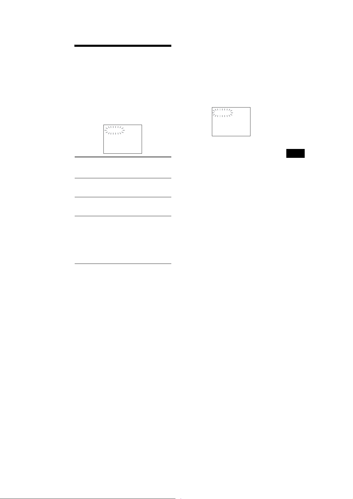
Self-diagnosis Function
(When letters/numbers appear in the
display)
When the self-diagnosis functionis activated to
prevent the system from malfunctioning,a 5character service number (e.g., C 1 3 50) with a
combination of a letter and 4 digits ap pears on
the TV screenorfront panel display. In thiscase,
check the followingtable.
C:13:50
HCD-DZ260/DZ270/HDZ278
When displaying the version
number on the TV screen
When you turn on the system, the version
number [VER.X.XX] (X is a number) may
appear on the TV screen. Although this is not a
malfunction and for Sony service use only,
normal system operation willnot be possible.
Turn off the system,andthen turn on thesystem
again to operate.
VER.X.XX
First 3
characters of
the service
number
C 13 The disc is dirty.
C 31 The disc is not inserted correctly.
EXX
(XX is a
number)
Cause and/or corrective action
Clean the disc with a soft cloth
(page 80).
Restart the system, then re-inser t
the disc correctly.
To preventa malfunction, the
system has performed the selfdiagnosis function.
Contact your nearestSony
dealer or local authorized Sony
service facility andgive the5character service number.
Example: E 61 10
Additional Information
89
GB
7

HCD-DZ260/DZ270/HDZ278
TABLE OF CONTENTS
1. SERVICING NOTES ............................................. 9
2. GENERAL .................................................................. 11
3. DISASSEMBLY
3-1. Case ................................................................................ 18
3-2. POWER Board ................................................................ 18
3-3. Front Panel Section ........................................................ 19
3-4. Back Panel Section ......................................................... 19
3-5. DVD Mechanism Deck ................................................... 20
3-6. MAIN Board ................................................................... 20
3-7. IO-SCART Board (DZ260),
IO-COMPONENT Board (DZ270/HDZ278) ................. 21
3-8. Tray ................................................................................. 21
3-9. Belt .................................................................................. 22
3-10. MS-203 Board ................................................................. 22
3-11. Base Unit ......................................................................... 23
3-12. Optical Pick-up ............................................................... 23
4. TEST MODE ............................................................ 24
5. ELECTRICAL ADJUSTMENTS ........................ 29
6. DIAGRAMS
6-1. Block Diagram –RF Section– ......................................... 32
6-2. Block Diagram –VIDEO Section– ................................. 33
6-3. Block Diagram –AUDIO Section– ................................. 34
6-4. Block Diagram –AMP Section– ..................................... 35
6-5. Block Diagram –POWER Section– ................................ 36
6-6. Printed Wiring Board –MAIN Board (Side A)– ............. 37
6-7. Printed Wiring Board –MAIN Board (Side B)– ............. 38
6-8. Schematic Diagram –MAIN Board (1/9)– ...................... 39
6-9. Schematic Diagram –MAIN Board (2/9)– ...................... 40
6-10. Schematic Diagram –MAIN Board (3/9)– ...................... 41
6-11. Schematic Diagram –MAIN Board (4/9),
MS-203 Board– ............................................................... 42
6-12. Schematic Diagram –MAIN Board (5/9)– ...................... 43
6-13. Schematic Diagram –MAIN Board (6/9)– ...................... 44
6-14. Schematic Diagram –MAIN Board (7/9)– ...................... 45
6-15. Schematic Diagram –MAIN Board (8/9)– ...................... 46
6-16. Schematic Diagram –MAIN Board (9/9)– ...................... 47
6-17. Printed Wiring Board –IO-SCART Board (DZ260)– ..... 48
6-18. Schematic Diagram –IO-SCART Board (DZ260)– ........ 49
6-19. Printed Wiring Board –IO-COMPONENT Board
(DZ270/HDZ278)– ......................................................... 50
6-20. Schematic Diagram –IO-COMPONENT Board
(DZ270/HDZ278)– ......................................................... 51
6-21. Printed Wiring Boards –JACK, P-SW Board– ............... 52
6-22. Schematic Diagram –JACK, P-SW Board– .................... 53
6-23. Printed Wiring Boards
–FL, MS-203, SPEAKER Board– .................................. 54
6-24. Schematic Diagram
–FL, MS-203, SPEAKER Board– .................................. 55
6-25. Printed Wiring Board –POWER Board– ........................ 56
6-26. Schematic Diagram –POWER Board– ........................... 57
7. EXPLODED VIEWS
7-1. Overall Section ............................................................... 70
7-2. Front Panel Section ......................................................... 71
7-3. Chassis Section ............................................................... 72
7-4. DVD Mechanism Deck Section (CDM85-DVBU102) .. 73
8. ELECTRICAL PARTS LIST .............................. 74
8
SECTION 1
SERVICING NOTES
HCD-DZ260/DZ270/HDZ278
NOTES ON HANDLING THE OPTICAL PICK-UP
BLOCK OR BASE UNIT
The laser diode in the optical pick-up block may suffer electrostatic break-down because of the potential difference generated by the
charged electrostatic load, etc. on clothing and the human body.
During repair, pay attention to electrostatic break-down and also
use the procedure in the printed matter which is included in the
repair parts.
The fl exible board is easily damaged and should be handled with
care.
NOTES ON LASER DIODE EMISSION CHECK
The laser beam on this model is concentrated so as to be focused
on the disc refl ective surface by the objective lens in the optical
pickup block. Therefore, when checking the laser diode emission,
observe from more than 30 cm away from the objective lens.
DISC TRAY LOCK
The disc tray lock function for the antitheft of an demonstration
disc in the store is equipped.
Setting Procedure :
1. Press the [
2. Press the [FUNCTION] button to set DVD function.
3. Insert a disc.
4. Press the [
seconds.
5. The message “LOCKED” is displayed and the tray is locked.
Releasing Procedure :
1. Press the [x] button and the [A] button simultaneously for fi ve
seconds again.
2. The message “UNLOCKED” is displayed and the tray is
unlocked.
Note: When “LOCKED” is displayed, the tray lock is not released by
turning power on/off with the [?/1] button.
] button to turn the set on.
?/1
] button and the [A] button simultaneously for fi ve
x
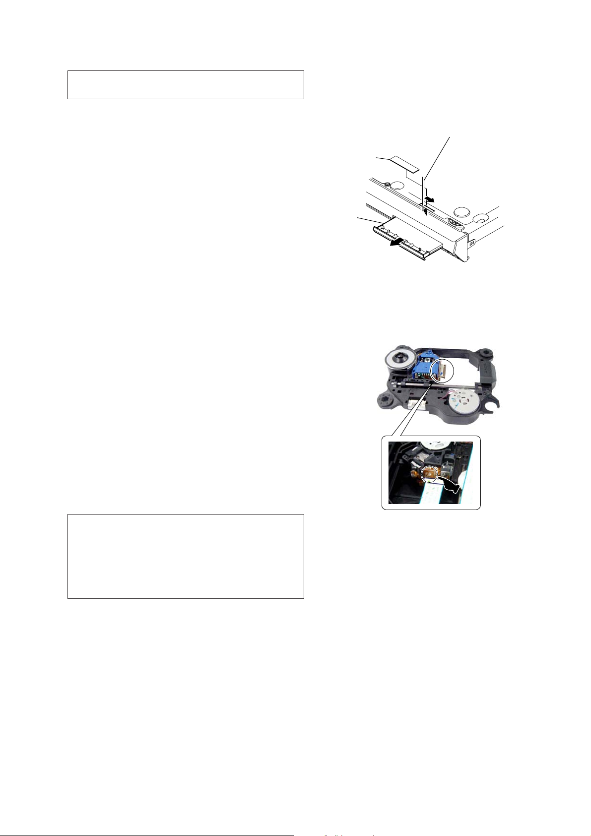
How to open the disc table when power switch turns off
Insert a tapering driver into the aperture of the unit bottom, and
slide it in the direction of the arrow.
Peel off the seal and so the lever is moved
in the direction of the arrow with the thin rod.
seal
tray
Precaution when installing a new OP unit/
Precaution before unsoldering the static electricity
prevention solder bridge
On cleaning discs, disc/lens cleaners
• Do not use cleaning discs or disc/lens cleaners (including wet or
spray types). These may cause the apparatus to malfunction.
IMPORTANT NOTICE
Caution: This system is capable of holding a still video image or
on-screen display image on your television screen indefi nitely.
If you leave the still video image or on-screen display image
displayed on your TV for an extended period of time you risk
permanent damage to your television screen.
Projection televisions are especially susceptible to this.
Attention when transported
Use this mode when returning the set to the customer after repair.
Procedure:
1. Press the [
2. Press the [FUNCTION] button to set the function “DVD”.
3. Remove all discs, and then press two buttons [
simultaneously.
4. After a message “MECHA LOCK” is displayed on the
fl uorescent indicator tube, pull out the AC plug.
5. To exit from this mode, press the [
on.
] button to turn the set on.
?/1
] and [
H
] button to turn the set
?/1
?/1
]
When installing a new OP unit, be sure to connect the fl exible
printed circuit board fi rst of all before removing the static electricity
prevention solder bridge by unsoldering.
Remove the static electricity prevention solder bridge by
unsoldering after the fl exible printed circuit board has already been
connected.
(Do not remove nor unsolder the solder bridge as long as the OP
unit is kept standalone.)
9
HCD-DZ260/DZ270/HDZ278
Ver. 1.1
Radiation Sheet
When peeling off the heat radiation sheet, try always to put it on
be former position.
POWER board
radiation sheet
10
SECTION 2
GENERAL
HCD-DZ260/DZ270/HDZ278
This section is extracted
from instruction manual.
Index to Parts and Control
(DZ260)
For more information, refer to th e pages indicated in parentheses.
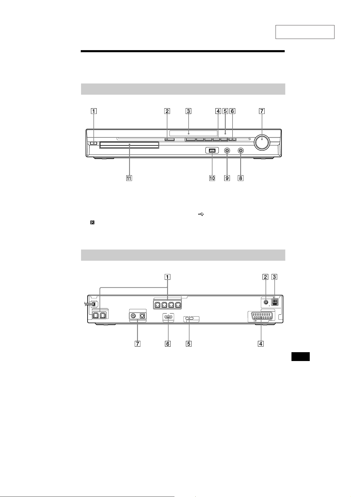
Front panel
" / (on/standby) (20, 78)
# " (open/close) (28)
$ Front panel display (96)
% Pl ay operation buttons (28)
& (remote senso r) (9)
' FUNCTION (23)
( VO LUME control (28)
) PHO NES jack (28)
* AUDIO IN/A.CAL MIC jack (16, 20, 72)
+ (USB)port(60)
, Disc tray (28)
Rear panel
SPEAKER
FRONTR FRONTL SUR R SUR L
SPEAKER
CENTER SUBWOOFER
" SPEAKER jacks (14)
# COA XIAL 75Ω FM jack (18)
$ AM terminal (18)
% EURO AV 5 OUTPUT (TO TV) jack (15)
DIGITAL IN
COAXIAL OPTICAL
TUOIMDHVT
ANTENNA
COAXIAL 75
AM
FM
EURO AV
DC5V
DMPORT
0.7A MAX
OUTPUT(TO TV)
& DMPORT (DIGITAL MEDIA PORT ) jack
(16, 69)
' HDM I OUT jack (15)
( TV (DIGITAL IN COAXIAL/OPTICAL)
jacks (15)
Additional Information
11

HCD-DZ260/DZ270/HDZ278
Front panel display
About the indications in the front panel display
" Playing status
# F lashes when the sleep timer is set.
(74)
$ Di splays system’sstatus such as
chapter, title, or track number, time
information, radio frequency, playing
status, decoding mode, etc.
% Lights up when a station is received.
(Radio only) (53)
& Stereo/Monaural effect (Radio only)
(54)
' Lig ht s up w henthe HDMI OUT jack is
correctly connected to HDCP (Highbandwidth Digital Content Protection)
compliant device with HDMI or DVI
(Digital Visual Interface) input. (15)
( Current surround format (Except for
JPEG image file)
) Lights up when an NTSC disc is
loaded.
* Lights up during USB recording/
copying. (66)
+ Lights up when Super Audio CD/CD is
loaded. (31)
12
96
GB
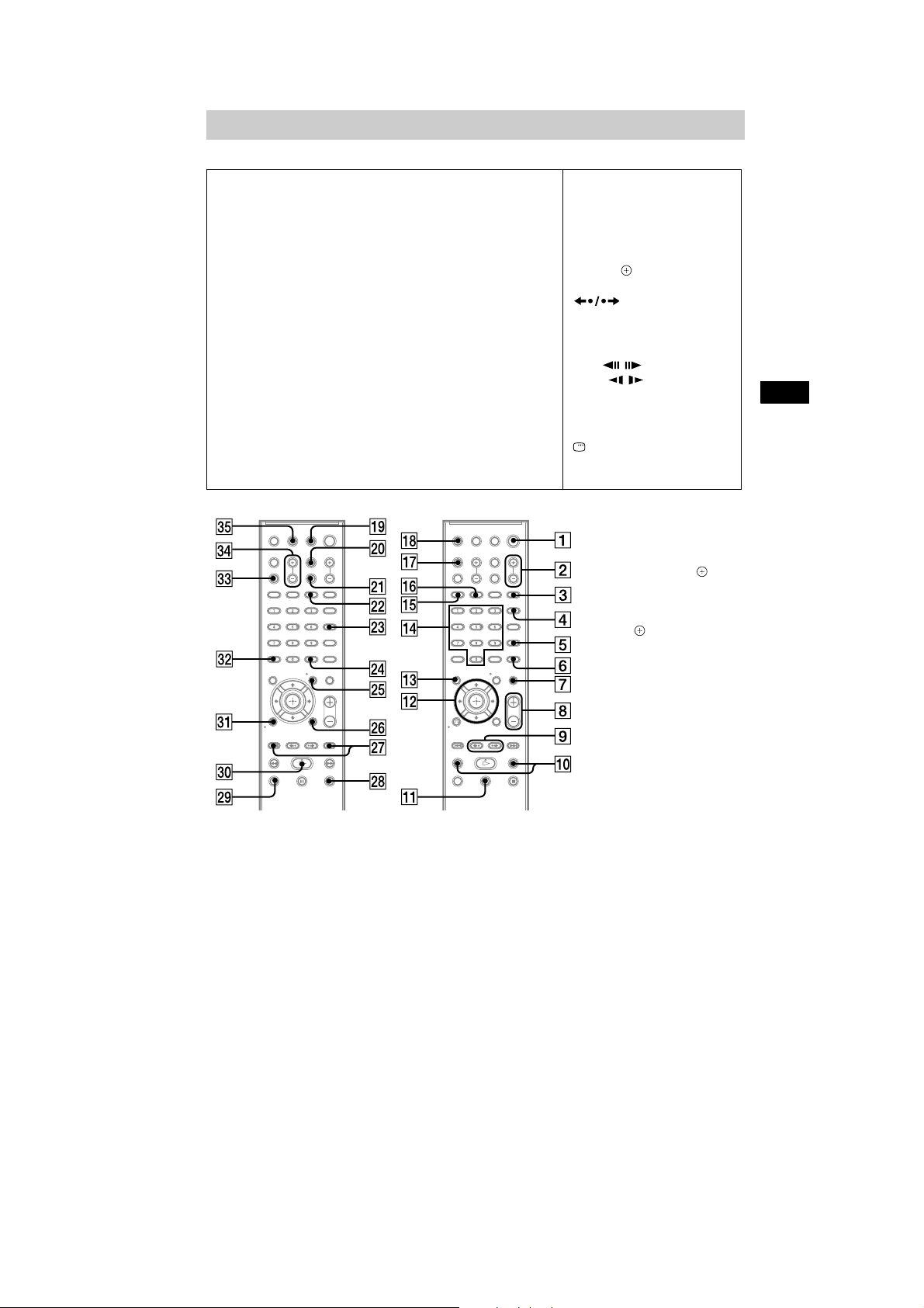
Remote control
ANGLE (29)
AUDIO RI (30)
CLEAR FT (34, 46, 54)
D.TUNING XT (54)
DISC SKIP
DISPLAY XB (55, 65, 75)
DVD MENU XH (36)
DVD TOP MENU RE (36)
DYNAMIC BASS (74)
ENTER
71)
FUNCTION +/– (23, 28)
MENU XH (73)
MUTING (28)
NIGHT XE (74)
ONE-TOUCH PLAY FH (58)
1)
FE
2)
XG (19,20, 31, 34, 53,
Z–PO–A
PICTURE NAVI RH (39, 62)
PRESET +/– XK (54)
PROG +/– XK (73)
S-AIR MODE
SLEEP RK (74)
SOUND MODE (27)
SUBTITLE XT (30)
SYSTEM MENU XG (19, 23,74,
75)
THEATRE RL (57)
TOOLS XI (73)
TUNING +/– (53)
TV XM (73)
TV INPUT X (73)
TV VOL +/– FG (73)
VOLUME +/– (28)
1)
HCD-DZ260/DZ270/HDZ278
SNOITPIRCSEDNOTTUBREDROLACITEBAHPLA
Number buttons RG (32, 53, 73)
</ (on/standby) (19,20, 28)
TV </ (on/standby) RM (73)
$/9/Y/D/ RT (19, 20, 31, 34,
53, 71)
(28)
/ XK (28)
N/. (28)
STEP / (28)
SLOW / (28)
)(play) F (28)
Y (stop) XL (28)
9 (pause) RB (28)
0 RETURNFB (32, 73)
-/-- FT (73)
REPLAY/ADVANCE
DISPLAY
3)
XI (20, 31, 34,71)
Additional Information
1)
This buttonis not available
for this model.
2)
The ENTER button has the
same function as the
button. When you operate
the TV, the ENTER button is
used forselecting a channel,
and the buttonisused for
selecting menu items
(page 73).
3)
This button is only available
for the “DVD” or “USB”
function.
97
GB
13

HCD-DZ260/DZ270/HDZ278
Index to Parts and Control
(DZ270/HDZ278)
For more information, refer to the pages ind ic at ed in paren th es es.
Front panel
" / (on/standby) (27, 85)
# " (open/close) (35)
$ Front panel d isplay (105)
% Play operation buttons (35)
& (remote sensor) (11)
' FUNC TION (30)
( VOLUME control (35)
) PHONES jack (35)
* AUDIOIN/A.CAL MIC jack (21, 27, 79)
+ (USB) port (DAV-DZ270 only) (67)
, Di sc tray (35)
Additional Information
Rear panel
DAV-DZ270
SPEAKER
CENTER SUBWOOFER
DAV-HDZ278
SPEAKER
CENTER SUBWOOFER
DIGITAL IN
COAXIAL OPTICAL
SPEAKER
FRONTR FRONTL SUR R SUR L
HDMI OUT
SPEAKER
FRONTR FRONTL SUR R SUR L
TUOIMDHOEDIV/VT
DMPORT
DC5V
0.7A MAX
P
B/CBPR/CR
Y
COMPONENTVIDEO OUT
B/CBPR/CR
P
Y
COMPONENTVIDEO OUT
AUDIO IN
VIDEO OUT TV/VIDEO
AUDIO IN LR
VIDEO OUT
TV/VIDEO
ANTENNA
COAXIAL 75
AM
FM
LR
ANTENNA
COAXIAL 75
AM
FM
14
" SPEAKER jacks (16)
# COAX IAL 75Ω FM jack (24)
$ AM terminal (24)
% TV /VIDEO (AUDIO IN R/L) jacks (18, 21)
& VI DE O OUT jack (1 8)
' CO MP O NENT VIDEO OUT jacks (18)
( DMPORT (DIGITAL MEDIA PORT) jack
(DAV-HDZ278 only) (21, 76)
) HDMI OUT jack (18)
* TV/VIDEO (DIGITAL IN COAXIAL/
OPTICAL) jacks (DAV-HDZ278 only)
(18)

Front panel display
About the indications in the front panel display
HCD-DZ260/DZ270/HDZ278
" Playing status
# Flashes wh en th e sleep timer is set.
(81)
$ Displays system’s status such as
chapter, title, or track number, time
information, radio frequency, playing
status, decoding mode, etc.
% Lights up when a station is received.
(Radio only) (61)
& Stereo /Monaural effect (Radio only)
(62)
' Li ghts up w hen the HD MI OUT ja c k i s
correctly connected to HDCP (Highbandwidth Digital Content Protection)
compliant device with HDMI or DVI
(Digital Visual Interface) input. (18)
( Current surround format (Except for
JPEG image file)
) L ightsup when the color system is set
toNTSC. (Asian, Australian, and Middle
Eastern models only)
* L ig hts up dur in g USB recording/
copying. (DAV-DZ270 only) (73)
+ Lights up when Super Audio CD/CD is
loaded. (38)
Additional Information
105
GB
15
HCD-DZ260/DZ270/HDZ278
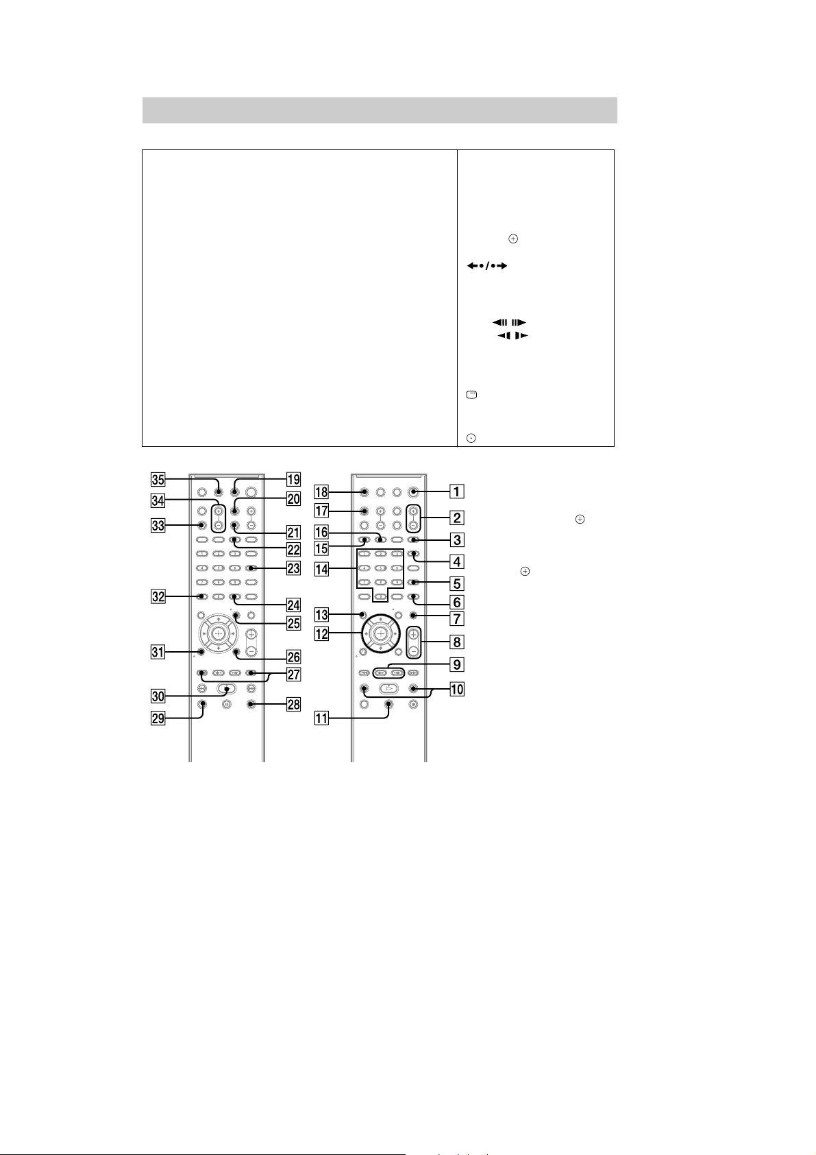
Remote control
ANGLE (36)
AUDIO RI (37)
CLEAR FT (40, 52, 62)
D.TUNING XT (62)
DISC SKIP
DISPLAY XB (63, 72, 82)
DVD MENU XH (43)
DVD TOP MENU RE (43)
DYNAMIC BASS (81)
ENTER
78)
FUNCTION +/– (30, 35)
MENU XH (80)
MUTING (35)
NIGHT XE (81)
ONE-TOUCH PLAY FH (65)
1)
FE
2)
XG (26, 27, 38, 40, 61,
Z–PO–A
PICTURE NAVI RH (45, 69)
PRESET +/– XK (62)
PROG +/–
S-AIR MODE
3)
XK (80)
1)
SLEEP RK (81)
SOUND MODE (34)
SUBTITLE XT (37)
SYSTEM MENU XG (26, 31, 81,
82)
THEATER/THEATRE
4)
RL (64)
TOOLS XI (80)
TUNING +/– (61)
TV XM (80)
TV CH +/–
5)
XK (80)
TV INPUT X (80)
TV VOL +/– FG (80)
VOLUME +/– (35)
SNOITPIRCSEDNOTTUBREDROLACITEBAHPLA
Number buttons RG (39, 61, 80)
</ (on/standby) (26, 27, 35)
TV </ (on/standby) RM (80)
$/9/Y/D/ RT (26, 27, 38, 40,
61, 78)
REPLAY/ADVANCE
(35)
/ XK (35)
N/. (35)
STEP / (35)
SLOW / (35)
)(play) F (35)
Y (stop) XL (35)
9 (pause) RB (35)
DISPLAY
0 RETURN FB (39, 80)
3)
-/--
5)
FT (80)
FT (80)
6)
XI (27, 38, 40, 78)
106
1)
This buttonis not available
for this model.
2)
The ENTER button has the
same function as the
button. When you operate
the TV, the ENTER button is
used forselecting a channel,
and the buttonisused for
selecting menu items
(page 80).
3)
Except for North American
models.
4)
The buttonname diff ers
depending on the area.
5)
North American models
only.
6)
This button is only available
for the “DVD” or “USB*”
function.
* DAV-DZ270only
GB
16
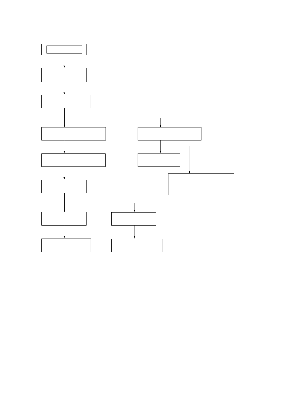
DISASSEMBLY
• This set can be disassembled in the order shown below.
SET
3-1. CASE
(Page 18)
3-2. POWER BOARD
(Page 18)
SECTION 3
HCD-DZ260/DZ270/HDZ278
Ver. 1.1
3-3. FRONT PANEL SECTION
(Page 19)
3-5. DVD MECHANISM DECK
(Page 20)
3-8. TRAY
(Page 21)
3-9. BELT
(Page 22)
3-10. MS-203 BOARD
(Page 22)
3-4. BACK PANEL SECTION
(Page 19)
3-6. MAIN BOARD
(Page 20)
3-7. IO-SCART BOARD (DZ260)
IO-COMPONENT BOARD
(DZ270/HDZ278)
(Page 21)
3-11. BASE UNIT
(Page 23)
3-12. OPTICAL PICK-UP
(Page 23)
17
HCD-DZ260/DZ270/HDZ278
Note: Follow the disassembly procedure in the numerical order shown below.
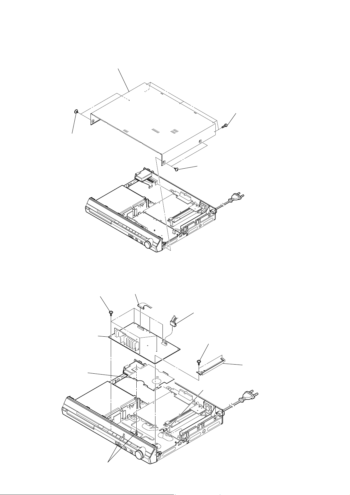
3-1. CASE
case
two screws
(case 3 TP2)
five screws
(BV/RING)
two screws
(case 3 TP2)
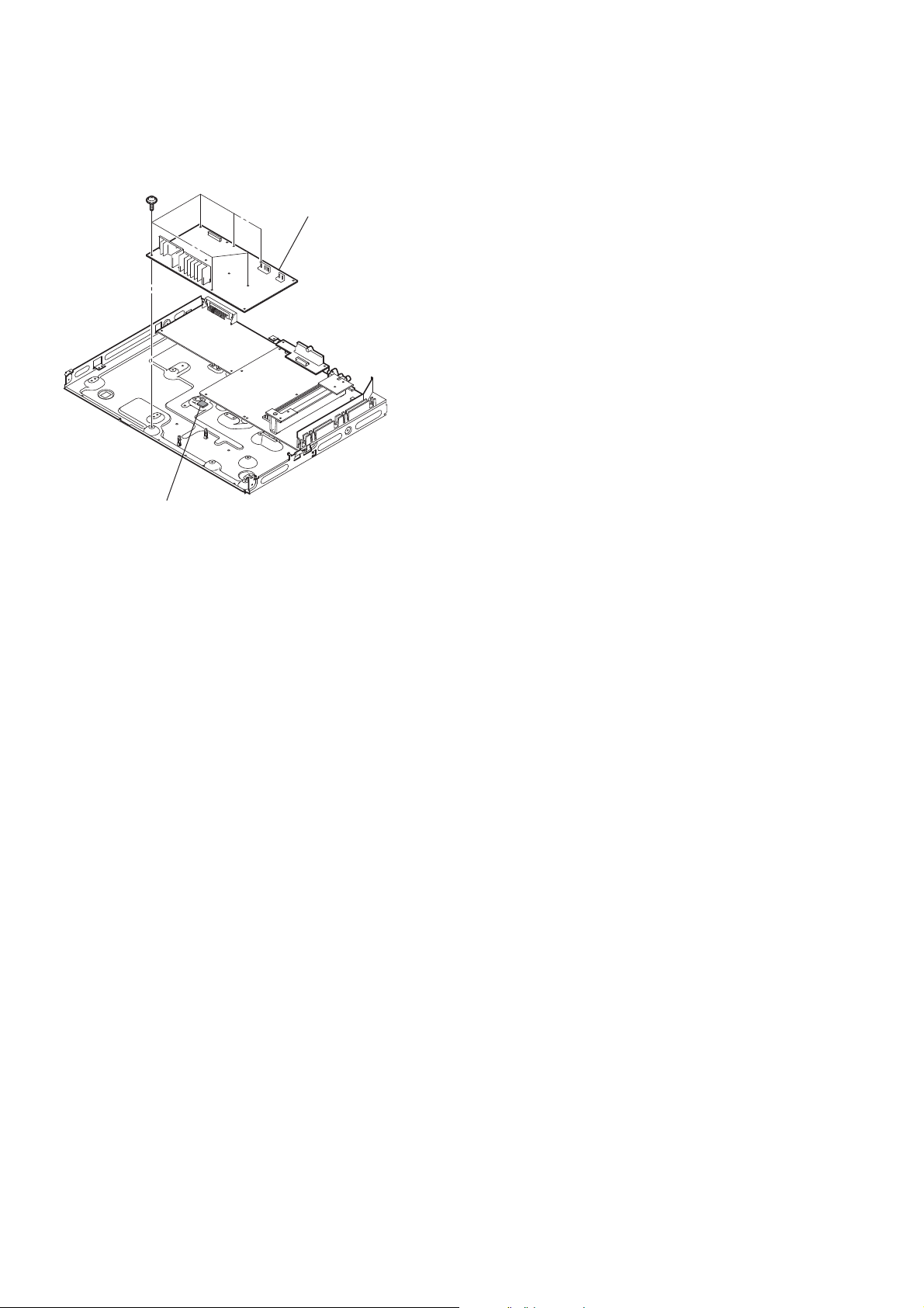
3-2. POWER BOARD
POWER board
cover (USB)
six screws
(+PWH 3 × 8)
CN906 (13P)
CN904 (4P)
two screws
(+PWH 3 × 8)
shield plate (HP)
CN3001 (4P)
18
two claws
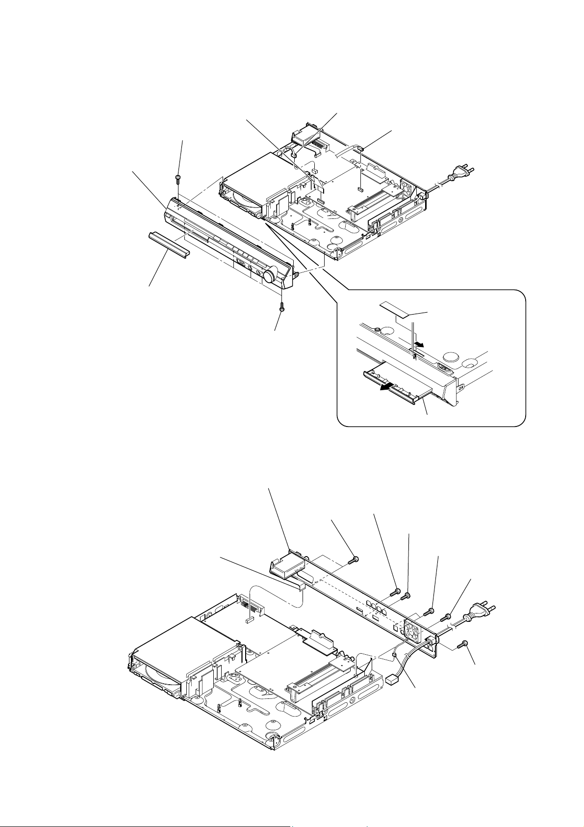
3-3. FRONT PANEL SECTION
HCD-DZ260/DZ270/HDZ278
front panel section
loading panel
wire (flat type)(19 core)
(CN502)
two screws
(+BV3 (3-CR))
five screws
(+BV3 (3-CR))
CN412 (4P) (DZ260/DZ270)
CN2101 (5P)
label
3-4. BACK PANEL SECTION
wire (flat type) (11 core) (CN414) (DZ260)
wire (flat type) (9 core) (CN419) (DZ270/HDZ278)
back panel section
two screws
(+BVTP 3 × 8)
tray
screw
(+BVTP 3 × 8)
screw
(+B 3 × 6)
two screws
(+BVTP 3 × 8)
two screws
(+BVTP 3 × 8)
screw
(+BVTP 3 × 8)
CN3000 (2P)
19
HCD-DZ260/DZ270/HDZ278
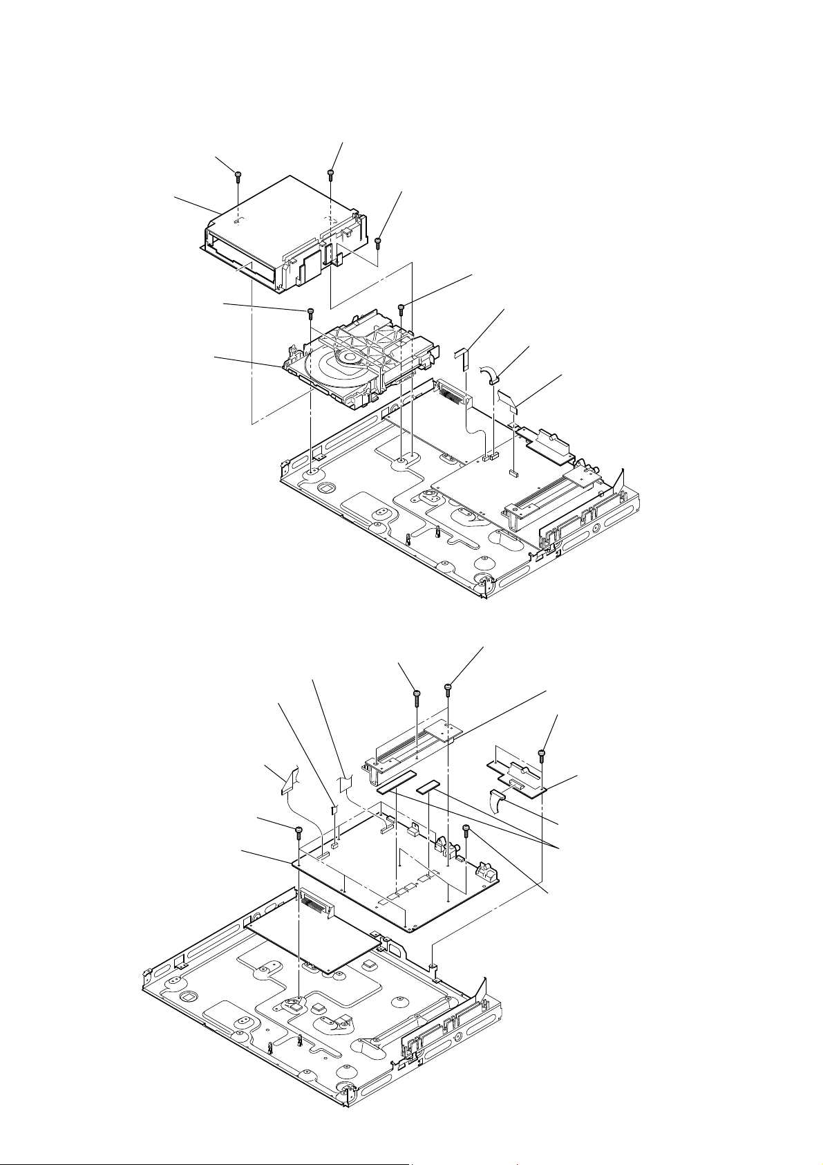
3-5. DVD MECHANISM DECK
screw
(+BV3 (3-CR))
cover (CDM-DSR)
two screws
(+BV3 (3-CR))
DVD mechanism deck
screw
(+BV3 (3-CR))
screw
(+BV3 (3-CR))
screw
(+BV3 (3-CR))
wire (flat type)(5 core)
(CN1202)
CN1201 (6P)
wire (flat type)(24 core)
(CN101)
3-6. MAIN BOARD
wire (flat type) (19 core) (CN4301) (DZ260)
wire (flat type) (15 core) (CN4303) (DZ270)
wire (flat type) (17 core) (CN4302) (HDZ278)
wire (flat type) (19 core) (CN602)
(DZ260)
wire (flat type) (17 core) (CN603)
(DZ270/HDZ278)
wire (flat type)(5 core)
(CN702)
RT six screws
(+BV3 (3-CR))
RE MAIN board
screw
(+BVTP 3 × 12)
two screws
(+BV3 (3-CR))
heat sink section
two screws
(+BV3 (3-CR))
SPEAKER board
CN1141 (8P)
two radiation sheet
RB two screws
(+BV3 (3-CR))
20

HCD-DZ260/DZ270/HDZ278
3-7. IO-SCART BOARD (DZ260), IO-COMPONENT BOARD (DZ270/HDZ278)
two screws
(+BV3 (3-CR))
IO-SCART board (DZ260)
IO-COMPONENT board (DZ270/HDZ278)
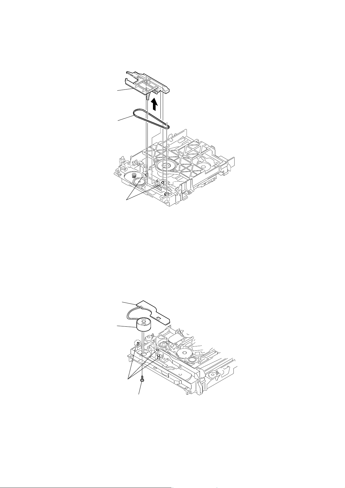
3-8. TRAY
Move the chuck cam
in the direction of the arrow.
bottom side
two claws
tray
21
HCD-DZ260/DZ270/HDZ278
3-9. BELT
chuck cam
belt
3-10. MS-203 BOARD
two claws
MS-203 board
DC motor
22
three claws
screw
(M 1.7 × 2.5)
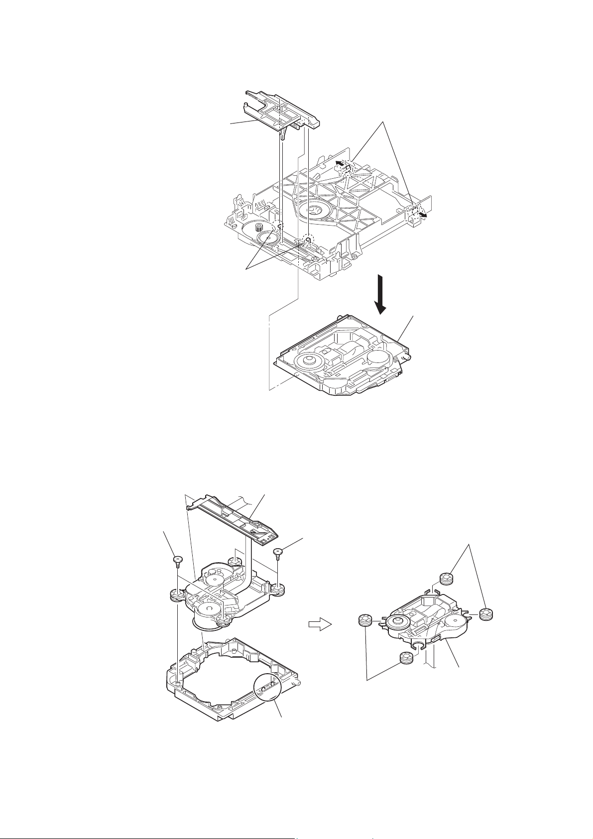
3-11. BASE UNIT
HCD-DZ260/DZ270/HDZ278
chuck cam
two claws
two claws
base unit
3-12. OPTICAL PICK-UP
two insulator screws
FFC holder
two insulator screws
two claws
two insulators
two insulators
optical pick-up
(KHM-313CAA)
23

HCD-DZ260/DZ270/HDZ278
Ver. 1.1
SECTION 4
TEST MODE
Note: Incorrect operations may be performed if the test mode is not
entered properly.
In this case, press the [?/1] button to turn the power off, and
retry to enter the test mode.
1. Cold Reset
• The cold reset clears all data including preset data stored in the
RAM to initial conditions. Execute this mode when returning
the set to the customers.
Procedure:
1. Press the [
2. Press three buttons [x], [A] and [
] button to turn the power on.
?/1
?/1
] simultaneously.
3. When this button is operated, display as “COLD RESET” for
a while and all of the settings are reset.
2. Panel Test Mode
• This mode is used to check the software version, FL and
KEY.
2-1. Display Test Mode
Procedure:
1. Press the [
2. Press three buttons [
] button to turn the power on.
?/1
], [.] and [A] simultaneously.
X
3. When the display test mode is activated, all segments are turned
on.
4. To exit from this mode, press three buttons [X], [.] and [A]
simultaneously.
2-2. Version Test Mode
Procedure:
1. When the display test mode is activated, press the [.] button
and the message “DSR2E” (DZ260), “DSR2N” (HDZ278),
“DSR2” (DZ270) are displayed, the version test mode is
activated.
2. Whenever the [.] button is pressed, the display changes in
the following order.
“DSR2E” (Model name) U“CE2*1” (Destination) U
UMC V ersion U SYS V ersion UUI Version U
UDVD V ersion UST V ersion U T A V ersion U
UDSP V ersion UTM V ersion UMM Version U
U CLA Version UCEC Version USAIR Version
*1: CE2 changes depending on destination.
3. Press the [>] button and the date of the software production
is displayed.
4. Press the [>] button again and the version is displayed.
5. To exit from this mode, press three buttons [X], [.] and [A]
simultaneously.
2-3. Key Test Mode
Procedure:
1. When the display test mode is activated, press the [H] button,
to select the key test mode.
2. To enter the KEY test mode, the fl uorescent indicator displays
“K0 V0”. Each time an another button is pressed, “KEY” value
increases. However, once a button is pressed, it is no longer
taken into account. When all keys are pressed correctly, “K8
V0” is displayed.
3. When the [VOLUME] control is turned in the direction of (+),
“V0” is changed to “V1”, then ... “V9”.
When the [VOLUME] control is turned in the direction of (–),
“V0” is changed to “V9”, then ... “V1”.
4. To exit from this mode, press three buttons [X], [.] and [A]
simultaneously.
3. Disc Tray Lock
The disc tray lock function for the antitheft of an demonstration
disc in the store is equipped.
Setting Procedure :
1. Press the [
] button to turn the set on.
?/1
2. Press the [FUNCTION] button to set DVD function.
3. Insert a disc.
4. Press the [
] button and the [A] button simultaneously for fi ve
x
seconds.
5. The message “LOCKED” is displayed and the tray is locked.
Releasing Procedure :
1. Press the [
] button and the [A] button simultaneously for fi ve
x
seconds again.
2. The message “UNLOCKED” is displayed and the tray is
unlocked.
Note: When “LOCKED” is displayed, the tray lock is not released by
turning power on/off with the [
?/1] button.
4. DVD Ship Mode
Use this mode when returning the set to the customer after repair.
Procedure:
1. Press the [
] button to turn the set on.
?/1
2. Press the [FUNCTION] button to set the function “DVD”.
3. Remove all discs, and then press two buttons [
H
] and [
?/1
simultaneously.
4. After a message “MECHA LOCK” h “PULL PLUG” is
displayed on the fl uorescent indicator tube, pull out the AC
plug.
5. To exit from this mode, press the [
] button to turn the set
?/1
on.
5. AM Step Change (Except AEP, UK, E models)
• A step of AM channels can be changed over between 9 kHz
and 10 kHz.
Procedure:
1. Press the [
] button to turn the set ON.
?/1
2. Select the function “TUNER”, and press [FUNCTION] button
to select the BAND “AM”.
3. Press the [
4. Press two buttons [>] and [
] button to turn the set OFF.
?/1
?/1
] simultaneously, and the
display of fl uorescent indicator tube changes to “AM 9k STEP”
or “AM 10k STEP”, and thus the channel step is changed
over.
6. Product Out
This mode moves the optical pick-up to the position durable to
vibration and clears all data including preset data stored in the
RAM to initial conditions. Use this mode when returning the set to
the customer after repair.
Procedure:
1. Press the [
] button to turn the power on.
?/1
2. Press the [FUNCTION] button to set the function “DVD”.
3. Remove all discs, and then press three buttons [
] simultaneously.
[
?/1
], [A] and
>
4. After the “STANDBY” blinking display fi nishes, the message
“MECHA LOCK” h “PULL PLUG” is displayed on the
fl uorescent indicator tube disconnect the AC power plug, then
the ship mode is set.
]
24

HCD-DZ260/DZ270/HDZ278
DVD SECTION
7-1. GENERAL DESCRIPTION
The IOP measurement allows you to make diagnosis and
adjustment simply by using the remote commander and monitor
TV. The instructions, diagnosis results, etc. are given on the onscreen display (OSD).
Be sure to execute the IOP measurement when a BU (Base Unit)
is replaced.
7-2. HOW TO ENTER TEST MODE
While pressing the [
] and [A] buttons simultaneously, turn
x
[VOLUME] control in the direction of (+) with the DVD player
in power on.
The Test Mode starts, displayed “SERVICE IN” on this model
display then the menu shown below will be displayed on the TV
screen.
* The display of the “Model Name” of the “Remocon Diagnosis
Menu” change with the model and the destination. Refer to
below on the model name.
DZ260 : DSR2E
HDZ278 : DSR2N
DZ270 : DSR2
Remocon Diagnosis Menu
0. External Chip Check
1. Servo Parameter Check
2. Drive Manual Operation
3. Emergency History
4. Version Information
(2) Select “2. Drive Manual Operation” by pressing the [2] button
on the remote commander. The screen will appear as shown.
Drive Manual Operation
1. Servo Control
2. Track/Layer Jump
3. Manual Adjustment
4. Tray Aging Mode
5. MIRR time adjust
0. Return to Top Menu
(3) Select “3. Manual Adjustment” by pressing the [3] button on
the remote commander. The screen will appear as shown.
Manual Adjust
1. Track Balance Adjust:
2. Track Gain Adjust:
3. Focus Balance Adjust:
4. Focus Gain Adjust:
5. Eq Boost Adjust:
6. Iop:
7. TRV. Level:
8. S curve(FE) Level:
9. RFL(PI) Level:
0. MIRR Time:
0P Change Value
[RETURN] Return to previous menu
(4) Select “6. IOP” by pressing the [6] button on the remote
commander.
1
Model Name
IF-con : Ver. XX.XX (XXXX)
Syscon : Ver. X.XXX
*1: Changes depending on destination
: DSR2E_XX
*
The menu above is the Remocon Diagnosis Menu screen which
consists of fi ve main functions. At the bottom of the menu screen,
the model name and IF-con version. To exit from the Test Mode,
press the power button on the remote commander.
7-3. EXECUTING IOP MEASUREMENT
In order to execute IOP measurement, the following standard
procedures must be followed.
(1) In power on, while pressing the [
] and [A] buttons
x
simultaneously, turn the [VOLUME] control in the direction
of (+).
Remocon Diagnosis Menu
0. External Chip Check
1. Servo Parameter Check
2. Drive Manual Operation
3. Emergency History
4. Version Information
1
Model Name
IF-con
Syscon : Ver. X.XXX
*1: Changes depending on destination
: DSR2E_XX
: Ver. XX.XX (XXXX)
*
(5) Wait until a hexadecimal number appear.
Manual Adjust
1. Track Balance Adjust:
2. Track Gain Adjust:
3. Focus Balance Adjust:
4. Focus Gain Adjust:
5. Eq Boost Adjust:
6. Iop. 5B:
7. TRV. Level:
8. S curve(FE) Level:
9. RFL(PI) Level:
0. MIRR Time:
0P Change Value
[RETURN] Return to previous menu
(6) Convert each data from hexadecimal to decimal using
conversion table.
(7) Please fi nd the label on the rear of the BU (Base Unit).
The default IOP value is written in the label.
(8) Subtract between these two values.
(9) If the remainder is smaller than 93 (decimal), then it is OK.
However if the value is higher than 93, then the BU is defective
and need to be change.
(10) Press the [RETURN] button on the remote commander to
return back to previous menu.
(11) Press the [0] button on the remote commander to return to T op
Menu.
25

HCD-DZ260/DZ270/HDZ278
7-4. EMERGENCY HISTORY
To check the emergency history, please follow the following
procedure.
(1) From the Top Menu of Remocon Diagnosis Menu, select “3.
Emergency History Check” by pressing the [3] button on the
remote commander. The following screen appears on the onscreen display.
Emg. History Check
Laser Hours CD 999h 59min
01. 01 05 04 04
00 00 00 00 00 00 23 45
02. 02 02 01 01 00 A9 4B 00
00 00 00 00 00 00 23 45
[Next] Next Page [Prev] Prev Page
[O] Return to Top Menu
DVD 999h 59min
00 92 46 00
(2) You can check the total time when the laser is turned on during
playback of DVD and CD from the above menu. The maximum
time, which can be displayed are 999h 59min.
(3) You can check the error code of latest 10 emergency history
from the above menu. To view the previous or next page of
emergency history, press [.] or [>] button on the remote
commander. The error code consists of the following three
blocks. The fi rst block indicates the error code. The second
block indicates the parameter and the third block indicates the
time of error code as shown below.
• Error Code
Emg. History Check
Laser Hours CD 999h 59min
*1 *2
01. 01 05 04 04
00 00 00 00 00 00 23 45
02. 02 02 01 01 00 A9 4B 00
00 00 00 00 00 00 23 45
[Next] Next Page [Prev] Prev Page
[O] Return to Top Menu
DVD 999h 59min
00 92 46 00
*3
*1 : Error Code
*2 : Parameter of error code
*3 : Time of error code
60: Focus on error
61: Seek fail error
62: Read Q data/ID error
70: Lead in data read fail
71: TOC read time out (CD)
80: Can’t buffering
81: Unknown media type
7-4-1. Clear the Laser Hour
Press [
DISPLAY] button and then press [CLEAR] button on
the remote commander. The data for both CD and DVD data are
reset.
Emg. History Check
Laser Hours CD 0h 0min
01. 01 05 04 04
00 00 00 00 00 00 23 45
02. 02 02 01 01 00 A9 4B 00
00 00 00 00 00 00 23 45
[Next] Next Page [Prev] Prev Page
[O] Return to Top Menu
DVD 0h 0min
00 92 46 00
7-4-2. Clear the Emergency History
Press [DVD TOP MENU] button and then press [CLEAR] button
on the remote commander. The error code for all emer gency history
would be reset.
Emg. History Check
Laser Hours CD 999h 59min
01. 00 00 00 00
00 00 00 00 00 00 00 00
02. 00 00 00 00 00 00 00 00
00 00 00 00 00 00 00 00
[Next] Next Page [Prev] Prev Page
[O] Return to Top Menu
DVD 999h 59min
00 00 00 00
7-4-3. Clear the Initialize Setup Data
Press [DVD MENU] button and then press [CLEAR] button on the
remote commander.
Emg. History Check
The meaning of error code is as below:
01: Communication error (No reply from syscon)
02: Syscon hung up
03: Power OFF request when syscon hung up
19: Thermal shutdown
24: MoveSledHome error
25: Mechanical move error (5 Changer)
26: Mechanical move stack error
30: DC motor adjustment error
31: DPD offset adjustment error
32: TE balance adjustment error
33: TE sensor adjustment error
34: TE loop gain adjustment error
35: FE loop gain adjustment error
36: Bad jitter after adjustment
40: Focus NG
42: Focus layer jump NG
52: Open kick spindle error
51: Spindle stop error
26
Laser Hours
[Next] Next Page [Prev] Prev Page
[O] Return to Top Menu
CD 999h 59min
DVD 999h 59min
initialize setup data...
HCD-DZ260/DZ270/HDZ278
7-4-4. Return to the Top Menu of Remocon Diagnosis
Menu
Press [0] button on the remote commander.
• Check Version Information
To check the version information, please follow the following
procedure.
(1) From the Top Menu of Remocon Diagnosis Menu, select “4.
Version Information” by pressing the [4] button on the remote
commander. The following screen appears on the on-screen
display.
Version information
Firm (Main) : Ver. xxxxx
Firm (Sub) : xxxxx
RISC : xxxxx
8032 : xxxxx
Audio DSP : xxxxx
Servo DSP : xxxxx
[O] Return to Top Menu
To return to the Top Menu of Remocon Diagnosis Menu, press
[0] button on the remote commander.
8. DEMO PLAY OUT
It is a mode to release the demonstration reproduct by the dedicated
demonstration disc.
1. During playback the DEMO Disc, press the [x] and [H]
buttons for fi ve seconds simultaneously.
2. The message “DEMO OFF” is displayed, a mode to reproduct
the demonstration is released.
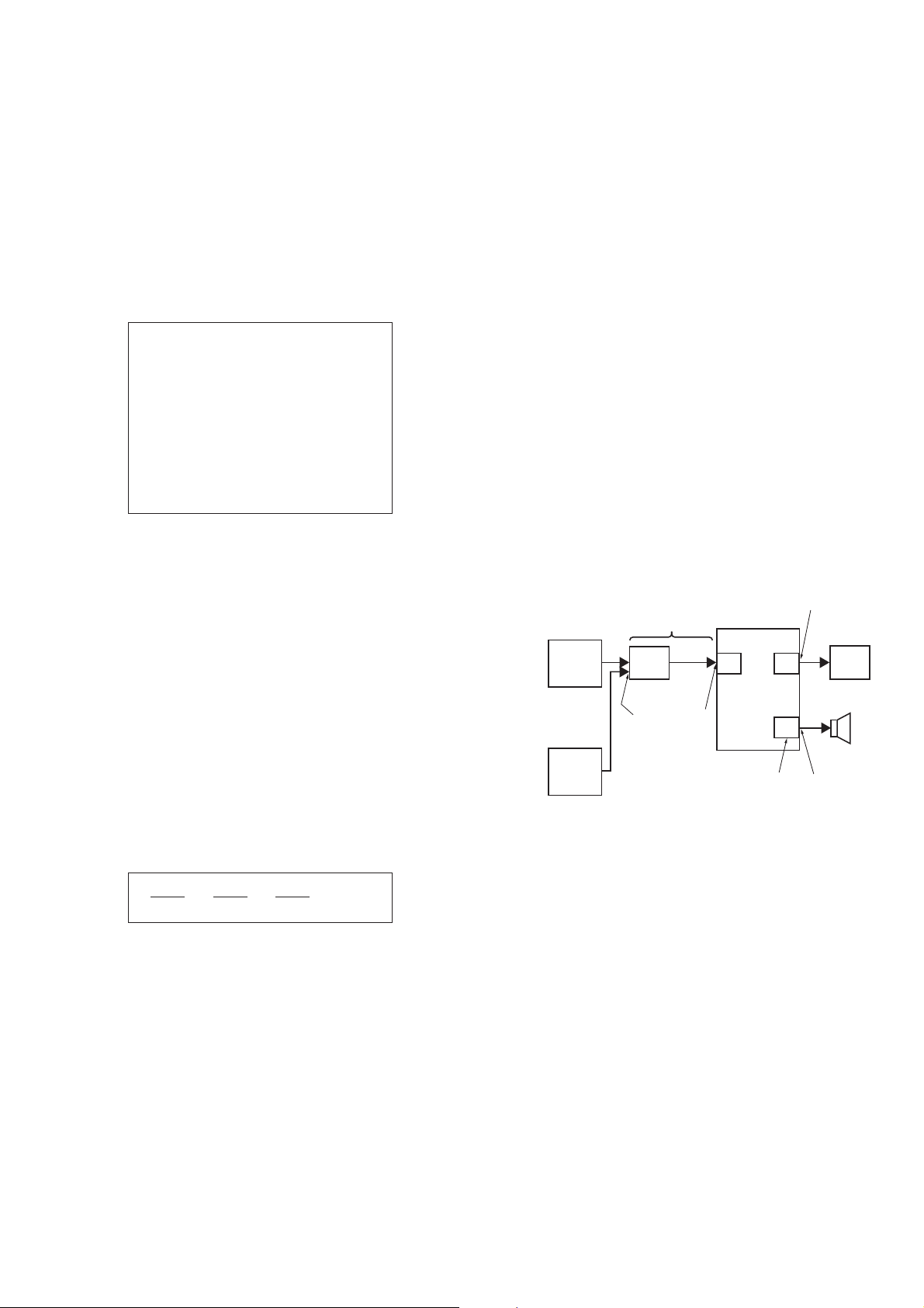
9. DIGITAL MEDIA PORT TEST
1. Connect the DMPORT CHECK JIG (P/N: J-2501-309-A) with
the terminal DMPORT.
2. Press the [
] button to turn the power on.
?/1
3. Confi rm that both LEDs of the DMPORT confi rmation JIG
lights. (Confi rmation the power supply line.)
4. Set the [FUNCTION] button with “DMPORT” on this model.
5. Press the [X], [.] buttons and turn the [VOLUME] control
in the direction of (+) simultaneously, the DMPORT test mode
is activated.
6. It is confi rmed that “DMPORT OK” is displayed on this set
display. (Confi rmation of communication line)
7. To a pin jack of the DMPORT confi rmation JIG input
information relevant to audio signal (sine-wave 1.0Vrms) and
composite video signal (white 100% 1.0Vp-p, color bar, etc.)
8. Confi rm the output of speakers and monitor TV. (Confi rmation
of analog signal)
9. To exit from this mode, press the [X], [.] buttons and turn
the [VOLUME] control in the direction of (+).
7-5. AUTOMATIC ACOUSTIC FIELD CALIBRATION
MICROPHONE TEST MODE
Procedure:
1. Press the [
] button to turn the power on.
?/1
2. Press the [FUNCTION] button to set the function “ DVD”.
3. Insert ECM-AC2 supplied as an accessory into the AUDIO IN/
A.CAL MIC jack.
4. While pressing the [X] and [A] buttons simultaneously, turn
the [VOLUME] control in the direction of (+).
5. Confi rm that the following are shown on the display panel.
1 The JACK inserted/non-inserted detection display and the
STEREO/MONO detection display.
2 Presence of DIGITAL voice input to the microcomputer.
(OK: input, NG: no input)
3 The value of the MIC input to the microcomputer. (shown
“255h”)
“NON” : Not detected
“ST” : STEREO
“MN” : MONO
OK : input
NG : no input
VIDEO
AUDIO
color pattern
generator
AF oscillator
DMPORT
CHECK JIG
(P/N: J-2501-309-A)
J001 7
CN204
CN400 (DZ260)
J404 (DZ270/HDZ278)
SET
MAIN
board
IO-SCART or
IO-COMPONENT
board
SPEAKER
board
TV
FL speaker,
FR speaker
TB100
0-255 (Changes in real time)
6. To exit from this mode, press the [
] and [A] buttons simulta-
X
neously, turn the [VOLUME] control in the direction of (+).
27

HCD-DZ260/DZ270/HDZ278
Ver. 1.1
11. PROTECTION FACTOR (SD DETECTION/
DC DETECTION) IDENTIFICATION TEST MODE
When an error is detected, the FL tube alternately displays
“PROTECTOR h PUSH POWER”.
r Press the [
* Buttons other than the [
“STANDBY” blinks three times on the FL tube.
r
The protection release state (POWER OFF) is established.
(No FL tube display)
r Press the [
The power to the system turns on, and the normal operation is
established. (Restore)
During the protection state:
1. If the AC plug is connected or disconnected during the
protection state, the protection state is released, and the
normal operation is established. (The protection state is not
maintained.)
2. The protection factor is displayed by pressing the
[FUNCTION], [A] and [>] buttons at the same time during
the protection state
(during the “PROTECTOR h PUSH POWER” display).
k When SD is detected: Repeats
“SD DETECT h PROTECTOR”.
k When DC is detected: Repeats
“DC DETECT h PROTECTOR”.
] button.
?/1
] button two times.
?/1
] button are invalid.
?/1
PL: SD detection
When the “L” output from the SD (shutdown) port on the
S-MASTER POWER Driver Shutdown and voltage descent
(15 V or less) of 30 V power supply (PVDD) are detected.
DC detection
When the “L” output from the power/speaker error detection
circuit (DC detection port) is detected for two seconds
continually, the power system other than that of the FL tube
is turned off, and the protection state is established.
28
SECTION 5
ELECTRICAL ADJUSTMENTS
DVD SECTION
When the optical pick-up assy is replaced, perform the
“EXECUTING IOP MEASUREMENT”.
EXECUTING IOP MEASUREMENT (See page 25)
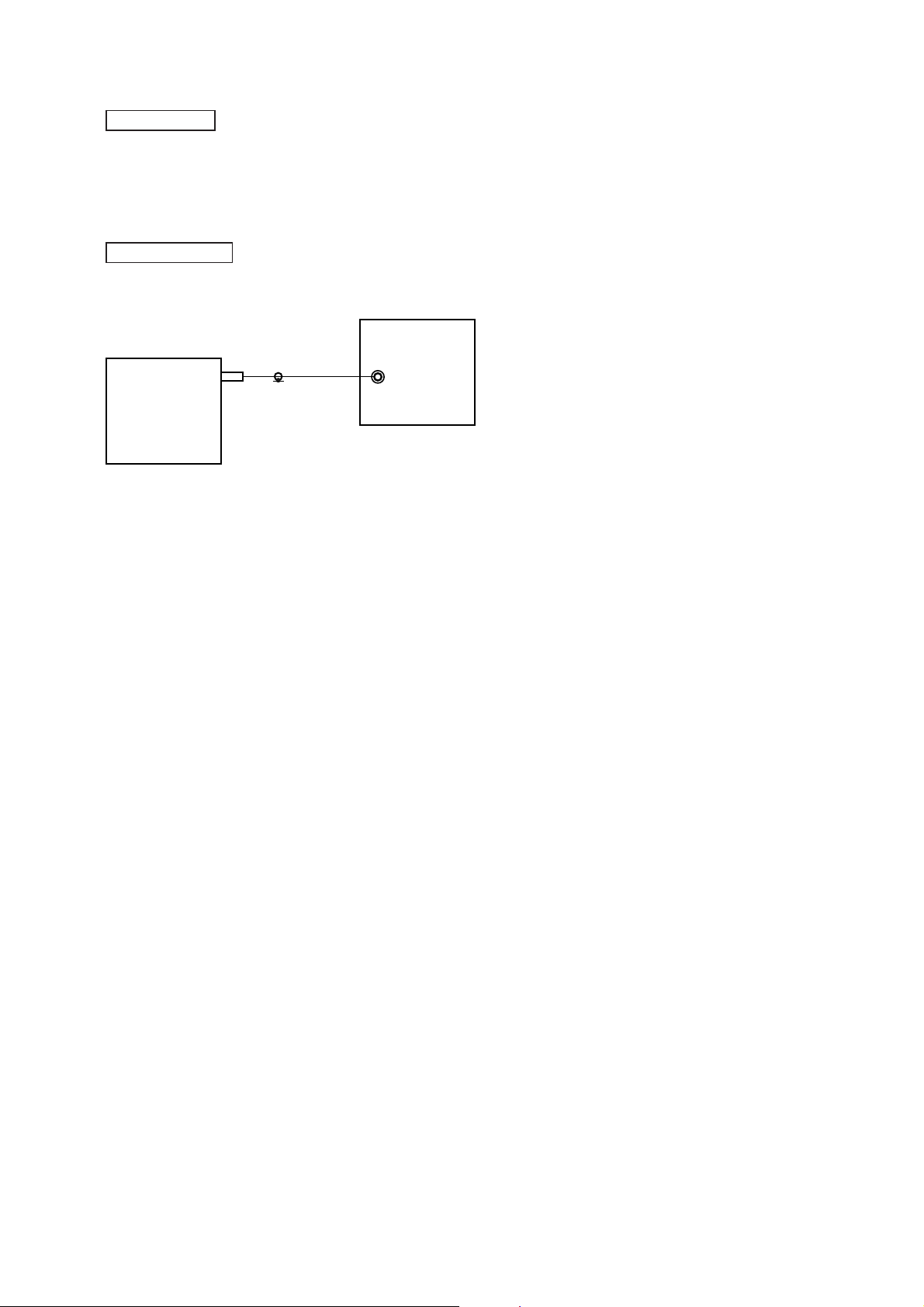
TUNER SECTION
[FM Tune Level Check]
generator
HCD-DZ260/DZ270/HDZ278
SET
Procedure:
1. Turn the power on.
2. Input the following signal from Signal Generator to FM
antenna input directly.
* Carrier Freq : A = 87.5 MHz, B = 98 MHz, C = 108 MHz
Deviation : 75 kHz
Modulation : 1 kHz
ANT input : 35 dBu (EMF)
Note: Please use 75 ohm “coaxial cable” to connect SG and the set. You
cannot use video cable for checking.
Please use SG whose output impedance is 75 ohm.
3. Set to FM tuner function and tune A, B and C signals.
4. Confi rm “TUNED” is lit on the display for A, B and C
signals.
The mark of “TUNED” means “The selected station signal is
received in good condition.”
OUT (75 Ω)
29
 Loading...