

Sony HCDDZ-265-K, HCDDZ-266-K, HCDDZ-270-K, HCDDZ-570-K, HCDDZ-777-K Service manual

HCD-DZ265K/DZ266K/DZ270K/
DZ570K/DZ777K
SERVICE MANUAL
Ver. 1.0 2008.04
Photo : HCD-DZ777K
• HCD-DZ265K/DZ266K/DZ270K/DZ570K/DZ777K
are the amplifi er, DVD/CD and tuner section in
DAV-DZ265K/DZ266K/DZ270K/DZ570K/DZ777K.
This system incorporates with Dolby* Digital and Dolby Pro
Logic (II) adaptive matrix surround decoder and the DTS** Digital
Surround System.
* Manufactured under license from Dolby Laboratories.
“Dolby”, “Pro Logic”, and the double-D symbol are trademarks
of Dolby Laboratories.
** Manufactured under license from DTS, Inc.
“DTS” and “DTS Digital Surround” are registered trademarks
of DTS, Inc.
SPECIFICATIONS
E Model
HCD-DZ270K/DZ570K/DZ777K
Russian Model
HCD-DZ265K/DZ266K
Model Name Using Similar Mechanism HCD-DZ260/DZ270/HDZ278
Mechanism Type CDM85-DVBU102
Optical Pick-up Name KHM-313CAA
Amplifi er Section
(DZ265K/DZ266K/DZ270K/DZ570K)
Stereo mode (rated) 108 W + 108 W (at 3 ohms,
1 kHz, 1% THD)
Surround mode (reference) RMS output power
FL/FR/C/SL/SR*: 142
watts (per channel at 3
ohms, 1 kHz, 10% THD)
Subwoofer*: 140 watts (at
3 ohms, 80 Hz, 10% THD)
* Depending on the decoding mode settings and the
source, there may be no sound output.
Inputs (Analog)
TV/VIDEO (AUDIO IN) Sensitivity: 450/250 mV
AUDIO IN/MIC1 Sensitivity: AUDIO IN
250/125 mV/MIC1 1 mV
MIC2 Sensitivity: 1 mV
Amplifi er Section (DZ777K)
Stereo mode (rated) 108 W + 108 W (at 3 ohms,
1 kHz, 1% THD)
Surround mode (reference) RMS output power
FL/FR/C/SL/SR*: 143
watts (per channel at 3
ohms, 1 kHz, 10% THD)
Subwoofer*: 285 watts (at
1.5 ohms, 80 Hz, 10% THD)
* Depending on the decoding mode settings and the
source, there may be no sound output.
Inputs (Analog)
TV (AUDIO IN) Sensitivity: 450/250 mV
SAT/CABLE (AUDIO IN) Sensitivity: 450/250 mV
AUDIO IN/MIC1 Sensitivity: AUDIO IN
250/125 mV/MIC1 1 mV
MIC2 Sensitivity: 1 mV
Super Audio CD/DVD System
Laser Semiconductor laser
(Super Audio CD/DVD: λ
= 650 nm)
(CD: λ = 790 nm)
Emission duration:
continuous
Signal format system
Russian models: PAL/NTSC
Other models: NTSC/PAL
USB Section
Supported bit rate
MP3 (MPEG 1 Audio Layer-3):
32 kbps - 320 kbps
WMA: 48 kbps - 192 kbps
AAC: 48 kbps - 320 kbps
Sampling frequencies
MP3 (MPEG 1 Audio Layer-3):
32/44.1/48 kHz
WMA: 44.1 kHz
AAC: 44.1 kHz
(USB) port:
Maximum current: 500 mA
Tuner Section
System PLL quartz-locked digital
synthesizer
FM tuner section
Tuning range 87.5 MHz - 108.0 MHz (50
kHz step)
Antenna (aerial) FM wire antenna (aerial)
Antenna (aerial) terminals 75 ohms, unbalanced
Intermediate frequency 10.7 MHz
AM tuner section
Tuning range
Russian model: 531 kHz - 1,602 kHz (with
the interval set at 9 kHz)
Other models: 531 kHz - 1,602 kHz (with
the interval set at 9 kHz)
530 kHz - 1,610 kHz (with
the interval set at 10 kHz)
Antenna (aerial) AM loop antenna (aerial)
Intermediate frequency 450 kHz
Video Section
Outputs VIDEO: 1 Vp-p 75 ohms
COMPONENT:
Y: 1 Vp-p 75 ohms
PB/CB, PR/CR: 0.7 Vp-p
75 ohms
HDMI OUT: Type A (19
pin)
– Continued on next page –
9-889-101-01
2008D04-1
2008.04
©
DVD RECEIVER
Sony Corporation
Audio Business Group
Published by Sony Techno Create Corporation
HCD-DZ265K/DZ266K/DZ270K/DZ570K/DZ777K
General
Power requirements
Saudi Arabia models: 127 V - 240 V AC, 50/60 Hz
Other models: 220 V - 240 V AC, 50/60 Hz
Power consumption
HCD-DZ265K/DZ266K: On: 155 W
Standby: 0.3 W (at the
Power Saving mode)
HCD-DZ270K: On: 160 W
Standby: 0.3 W (at the
Power Saving mode)
HCD-DZ570K/DZ777K: On: 170 W
Standby: 0.3 W (at the
Power Saving mode)
Output voltage (DIGITAL MEDIA PORT)
(HCD-DZ570K/DZ777K only)
DC 5 V
Output current (DIGITAL MEDIA PORT)
(HCD-DZ570K/DZ777K only)
700 mA
Dimensions (approx.) 430 mm × 66 mm × 385 mm
(w/h/d) incl. projecting parts
Mass (approx.) 4.2 kg
Design and specifi cations are subject to change
without notice.
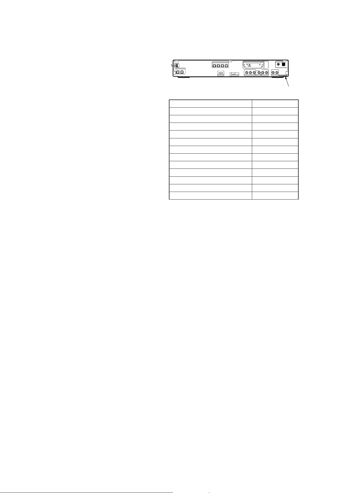
MODEL IDENTIFICATION
– Back Panel –
Model Part No.
DZ270K: SP model
DZ270K: TH model
DZ265K: RU model
DZ270K: EA model
DZ570K: SP model
DZ570K: TH model
DZ570K: EA model
DZ777K: SP model
DZ777K: TH model
DZ266K: RU model
DZ270K: PH model
DZ570K: PH model
Parts No.
3-273-759-3[]
3-273-759-4[]
3-273-759-6[]
3-273-760-7[]
3-273-761-2[]
3-273-761-8[]
3-273-762-4[]
3-273-763-0[]
3-273-763-4[]
3-273-763-6[]
3-273-763-9[]
3-273-764-8[]
• Abbreviation
EA : Saudi Arabia model
PH : Philippines model
SP : Singapore model
RU : Russian model
TH : Thai model
Special Component Notice
The components identifi ed by mark 9 contain confi dential infor-
mation.
Strictly follow the instructions whenever the components are repaired and/or replaced.
SAFETY-RELATED COMPONET WARNING!
COMPONENTS IDENTIFIED BY MARK 0 OR DOTTED LINE
WITH MARK 0 ON THE SCHEMATIC DIAGRAMS AND IN
THE PARTS LIST ARE CRITICAL TO SAFE OPERATION.
REPLACE THESE COMPONENTS WITH SONY PARTS
WHOSE PART NUMBERS APPEAR AS SHOWN IN THIS
MANUAL OR IN SUPPLEMENTS PUBLISHED BY SONY.
2
HCD-DZ265K/DZ266K/DZ270K/DZ570K/DZ777K
Laser component in this product is capable of emitting radiation exceeding the limit for Class 1.
This appliance is classifi ed as a
CLASS 1 LASER product.
This marking is located on the
rear or bottom exterior.
CAUTION
Use of controls or adjustments or performance of procedures other than
those specifi ed herein may result in hazardous radiation exposure.
Notes on chip component replacement
• Never reuse a disconnected chip component.
• Notice that the minus side of a tantalum capacitor may be dam-
aged by heat.
Flexible Circuit Board Repairing
• Keep the temperature of soldering iron around 270 °C during
repairing.
• Do not touch the soldering iron on the same conductor of the
circuit board (within 3 times).
• Be careful not to apply force on the conductor when soldering
or unsoldering.
About This Operating
Instructions
• The instructions in this Operating Instructions
describe the controls on the remote. You can
also use thecontrolsonthe unit if they have the
same or similar names as those on the remote.
• The Control M enu items may var y depending
on the area.
• “DVD” may be used as a general term for a
DVD VIDEO, D VD+RW /DVD+R, and DVDRW/DVD-R.
• Measurements are expressed in feet (ft) for
North American models.
• The defau lt setting is underlined.
About the S-AIR function
The system is compatible with the S-AIR
function, which allows transmission of sound
between S-AIR products wirelessly.
The following S-AIR products can be used with
the system:
UNLEADED SOLDER
Boards requiring use of unleaded solder are printed with the leadfree mark (LF) indicating the solder contains no lead.
(Caution: Some printed circuit boards may not come printed with
the lead free mark due to their particular size)
: LEAD FREE MARK
Unleaded solder has the following characteristics.
• Unleaded solder melts at a temperature about 40 °C higher
than ordinary solder.
Ordinary soldering irons can be used but the iron tip has to be
applied to the solder joint for a slightly longer time.
Soldering irons using a temperature regulator should be set to
about 350 °C.
Caution: The printed pattern (copper foil) may peel away if the
heated tip is applied for too long, so be careful!
• Strong viscosity
Unleaded solder is more viscous (sticky, less prone to fl ow)
than ordinary solder so use caution not to let solder bridges
occur such as on IC pins, etc.
• Usable with ordinary solder
It is best to use only unleaded solder but unleaded solder may
also be added to ordinary solder.
• Surround amplifier: You can enjoy surround
speaker sound wirelessly.
• S-AIR receiver: You can enjoy system sound
in another room.
These S-AIR products can be purchased as an
option (the S-AI R product lineup differs
depending on the area).
Notes or instructions for the surround amplifier
or S -AIR receiver in this operating instructions
refer only to when the surround amplifier or
S-AIR receiver is used.
For details on the S-AIR function, see “Using an
S-AIR Product” (page 83).
3

HCD-DZ265K/DZ266K/DZ270K/DZ570K/DZ777K
Playable Discs
• DVD-R/DVD-RW in DVD
VIDEO format or video mode
• DVD+R/DVD+RW in DVD
VIDEO format
nocIscitsiretcarahCogolcsiDepyT
OEDIVDVD•OEDIVDVD
VR (Video
Recording) mode
• DVD-R/DVD-RW in VR (Video
Recording) mode (except for
DVD-R DL)
DCoiduArepuS•DCoiduArepuS
•SuperVCD
• CD-R/CD-RW/CD-ROM in v ideo
CD format or Super VCD format
DCoiduA•DC
• CD-R/CD-RW in audio CD format
, and
, and
niMOR-DC/WR-DC/R-DC•–DCATAD
5)
Level 1/
/WR-DVD/R-DVD/MOR-DVD•–DVDATAD
D
A
TACD format,containingMP3
1)
files
, JPEG image files2),and
DivX video files
conforming to ISO 9660
Level 2, or Joliet (extended format)
DVD+R/DVD+RW in DATA
DVD format, containing MP3
1)
files
, JPEG image files2), and
DivX video files
conforming to UDF (Universal
Disk Format)
3)4)
3)4)
)scsid0.2dna1.1.reV(DCOEDIV•DCOEDIV
1)
MP3 (MPEG1 Audio Layer 3) is a standard format defined by ISO/MPEG which compresses audio data. MP3 files
must be in MPEG1 Audio Layer 3 format.
GB
4
4

HCD-DZ265K/DZ266K/DZ270K/DZ570K/DZ777K
2)
JPEG image files must conform to the DCF image file format. (DCF “Design rule for Camera File system”:Image
standards for digital cameras regulated by Japan Electronics and Information Technology Industries Association
(JEITA).)
3)
DivX®is a video file compression technology, developed by DivX, Inc.
4)
DivX, DivX Certified, and associated logos are trademarks of DivX, In c. and are used under license.
5)
A logical format of files and folders on CD-ROMs, defined b y ISO (International Organization for
Standardization).
“DVD-RW,” “DVD+RW,” “DVD+R,”“DVD VIDEO,” and the “CD” logos are trademarks.
Example of discs that the system cannot play
The system cannot play the following discs:
• CD -ROM/CD-R/CD-RW other than those recorded in the format s listed on page 4
• CD-ROM recorded in PHOTO CD format
• Data part of CD-Extra
•CDGraphicsdisc
• DVD Audio
• DATA DVD that does not contain MP3 files, JPEG image files, or DivX video files
• DVD-RAM
Also, the system cannot play the following discs:
• A DVD VIDEO with a different region code (page 6)
• A disc th at has a non-st andard shape (e.g., card, heart)
• A disc with paper or stickers on it
• A disc th at has the adhesive o f cellophane tape or a sticker still left on it
Note about CD-R/CD-RW/DVD-R/DVD-RW/DVD+R/DVD+RW
In some cases, CD-R/CD-RW/DVD-R/DVD-RW/DVD+R/DVD+RW cannot be played on this system
due to the recording quality o r physical condition of the disc, or the charact er i stics of the recordi ng
device and authoring software.
The disc will not play if it has not been correctly finalized. For more information, refer to the operating
instructions for the recording device.
Note that some playback functions may not work with some DVD+RWs/DVD+Rs, even if they h ave
been correctly finalized. In this case, view the disc by normal playback. Also some DATA CDs/DATA
DVDs created in P acket Write format cannot be played.
Music discs encoded with copyright protection technologies
This product is designed to play bac k discs that co nform to the Compact Disc (C D ) s ta ndard.
Recently, various music discs enc ode d with copyr i ght pr ot ection technologi es are marketed by some
record compani es. Please be aw are that among t hose discs, the re are som e t hat do not confor m to the
CD standard and may not b e playable by t hi s product.
Note on DualDiscs
A DualDisc is a two side d disc product w hi ch mates DVD recorded material on one side with digit al
audio material on the other side. How ever, since the audio material side does not conf or m to the
Compact Disc (CD) standard, p la yback on this pro duct is not guaranteed.
GB
5
5
HCD-DZ265K/DZ266K/DZ270K/DZ570K/DZ777K
About Multi Session CD
• This system can play a Multi Session CD when an MP3 file is contained in the first session. Any
subsequent MP3 files recorded in late r sessions can also be played back.
• This system can play a Multi Session CD when a JPEG image file is contained in the first session.
Any subsequent JPEG image files recorded in later sessions can also be played back.
• If MP3 files and JPEG image files in music CD format or video CD format are recorded in the first
session, only the first session will be played back.
Region code
Your system ha s a region code printed on the rea r of the unit and will only play a D V D labeled w i th
the same region code.
A DVD VID E O labeled will also play on this system.
If y ou try to play any other DVD VIDEO, the message [Playback prohibited by area limitations.] will
appear on the TV screen. Depending on the DVD VIDEO, no region code indication may be given even
though playing the DVD VIDEO is prohibited by area restrictions.
Note about playback operations of a DVD or VIDEO CD
ALL
Some playback operations on a DVD or VIDEO CD may be intentionally set by software producers.
Since this system will play a DVD or VIDEO CD according to the disc contents the software producers
designed,some playback features may not be available. Be sure to read the operating instructions
supplied with the DVD or VIDEO CD.
Copyrights
This product inco rporates copyright pr ot ection technolo gy that is prote cted by U.S. patents and other
intellectual propert y rights. Use of this cop yr i ght protection technology must be authorized by
Macrovision, and is intended for home and other limited viewing uses only unless otherwise authorized
by Macrovision. Reverse engineering or disassembly is prohibited.
This system incorporates with Dolby* Digital and Dolby Pro Logic (II) adaptive matrix surround
decoder and the DTS** Digital Surround System.
* Manufactured under license from Dolby Laboratories.
“Dolby”, “Pro Logic”, and the double-D symbol are trademarks of Dolby Laborato ries.
**Manufactured under license from DTS, Inc.
“DTS” and “D TS Digital Surround” are register e d trademarks of DTS, Inc.
This system incorporates High-Definition Multimedia Interface (HDMITM) technology.
HDMI, the HDMI logo and High-Definition Multimedia Interface are trademarks or registered
trademarks of HDMI Licensing LLC.
“BRAVIA” and are trademarks of Sony Corporation.
“S-AIR” and its logo are trademarks of Sony Corporation.
GB
6
6
HCD-DZ265K/DZ266K/DZ270K/DZ570K/DZ777K
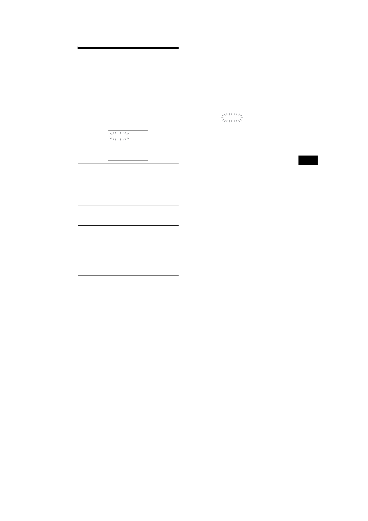
Self-diagnosis Function
(When letters/numbers appear in the
display)
When the self-diagnosis function is activated to
prevent the system from malfunctioning, a 5character service number (e.g., C 13 50) with a
combination of a letter and 4 digits appe ar s on
the TV screen or front panel display. In this case,
check the following table.
C:13:50
When displaying the version
number on the TV screen
When you turn on the sy st em , t h e version
number [VER.X.XX] (X is a number) may
appear on the TV screen. Although this is not a
malfunction and for Sony service use only,
normal system operation will not be po ss ible.
Turn off the system,and then turn on the system
again to operate.
VER.X.XX
First 3
characters of
the service
number
C 13 The disc is dirty.
C 31 The disc is not inserted correctly.
EXX
(XX is a
number)
Cause and/or correctivea ction
Clean the disc with a soft cloth
(page 103).
Restart the system, then re-insert
the disc correctly.
To prevent a malfunction, the
system has performed the selfdiagnosis function.
Contact your nearest Sony
dealer or local authorized Sony
service facility and give the 5character service number.
Example: E 61 10
Additional Information
113
GB
7

HCD-DZ265K/DZ266K/DZ270K/DZ570K/DZ777K
TABLE OF CONTENTS
1. SERVICING NOTES ............................................. 9
2. GENERAL .................................................................. 11
3. DISASSEMBLY
3-1. Case ................................................................................ 19
3-2. POWER Board ................................................................ 19
3-3. Front Panel Section ........................................................ 20
3-4. Back Panel Section ......................................................... 20
3-5. DVD Mechanism Deck ................................................... 21
3-6. MAIN Board ................................................................... 21
3-7. IO-COMPONENT Board, SCORE Board ...................... 22
3-8. Tray ................................................................................. 22
3-9. Belt .................................................................................. 23
3-10. MS-203 Board ................................................................. 23
3-11. Base Unit ......................................................................... 24
3-12. Optical Pick-up ............................................................... 24
4. TEST MODE ............................................................ 25
5. ELECTRICAL ADJUSTMENTS ........................ 30
6. DIAGRAMS
6-1. Block Diagram –RF Section– ......................................... 33
6-2. Block Diagram –VIDEO Section– ................................. 34
6-3. Block Diagram –AUDIO Section– ................................. 35
6-4. Block Diagram –S-AIR/USB Section– ........................... 36
6-5. Block Diagram –AMP Section– ..................................... 37
6-6. Block Diagram –POWER Section– ................................ 38
6-7. Printed Wiring Board –MAIN Board (Side A)– ............. 39
6-8. Printed Wiring Board –MAIN Board (Side B)– ............. 40
6-9. Schematic Diagram –MAIN Board (1/9)– ...................... 41
6-10. Schematic Diagram –MAIN Board (2/9)– ...................... 42
6-11. Schematic Diagram –MAIN Board (3/9)– ...................... 43
6-12. Schematic Diagram –MAIN Board (4/9),
MS-203 Board– ............................................................... 44
6-13. Schematic Diagram –MAIN Board (5/9)– ...................... 45
6-14. Schematic Diagram –MAIN Board (6/9)– ...................... 46
6-15. Schematic Diagram –MAIN Board (7/9)– ...................... 47
6-16. Schematic Diagram –MAIN Board (8/9)– ...................... 48
6-17. Schematic Diagram –MAIN Board (9/9)– ...................... 49
6-18. Printed Wiring Board –SCORE Board– ......................... 50
6-19. Schematic Diagram –SCORE Board– ............................ 51
6-20. Printed Wiring Board –IO-COMPONENT Board– ........ 52
6-21. Schematic Diagram –IO-COMPONENT Board– ........... 53
6-22. Printed Wiring Boards –JACK, P-SW Board– ............... 54
6-23. Schematic Diagram –JACK, P-SW Board– .................... 55
6-24. Printed Wiring Boards
–FL, MS-203, SPEAKER Board– .................................. 56
6-25. Schematic Diagram –FL, SPEAKER Board– ................. 57
6-26. Printed Wiring Board –S-AIR-CON Board
(DZ570K/DZ777K)– ...................................................... 58
6-27. Schematic Diagram –S-AIR-CON Board
(DZ570K/DZ777K)– ...................................................... 59
6-28. Printed Wiring Board –POWER Board– ........................ 60
6-29. Schematic Diagram –POWER Board– ........................... 61
7. EXPLODED VIEWS
7-1. Overall Section ............................................................... 74
7-2. Front Panel Section ......................................................... 75
7-3. Chassis Section ............................................................... 76
7-4. DVD Mechanism Deck Section (CDM85-DVBU102) .. 77
8. ELECTRICAL PARTS LIST .............................. 78
8

HCD-DZ265K/DZ266K/DZ270K/DZ570K/DZ777K
SECTION 1
SERVICING NOTES
NOTES ON HANDLING THE OPTICAL PICK-UP
BLOCK OR BASE UNIT
The laser diode in the optical pick-up block may suffer electrostatic break-down because of the potential difference generated by the
charged electrostatic load, etc. on clothing and the human body.
During repair, pay attention to electrostatic break-down and also
use the procedure in the printed matter which is included in the
repair parts.
The fl exible board is easily damaged and should be handled with
care.
NOTES ON LASER DIODE EMISSION CHECK
The laser beam on this model is concentrated so as to be focused
on the disc refl ective surface by the objective lens in the optical
pickup block. Therefore, when checking the laser diode emission,
observe from more than 30 cm away from the objective lens.
LASER DIODE AND FOCUS SEARCH
1. Open the case and turn POWER on with no disc inserted.
2. Confi rm that the following operation is performed while
observing the objecting lens from the clearance of DVD
mechanism deck.
1) Confi rm that laser beam is spread.
2) Up and down motion of the objective lens. (2 times)
DISC TRAY LOCK
The disc tray lock function for the antitheft of an demonstration
disc in the store is equipped.
Setting Procedure :
1. Press the [
2. Press the [FUNCTION] button to set DVD function.
3. Insert a disc.
4. Press the [x] button and the [A] button simultaneously for fi ve
seconds.
5. The message “LOCKED” is displayed and the tray is locked.
Releasing Procedure :
1. Press the [x] button and the [A] button simultaneously for fi ve
seconds again.
2. The message “UNLOCKED” is displayed and the tray is
unlocked.
Note: When “LOCKED” is displayed, the tray lock is not released by
turning power on/off with the [?/1] button.
On cleaning discs, disc/lens cleaners
• Do not use cleaning discs or disc/lens cleaners (including wet or
spray types). These may cause the apparatus to malfunction.
IMPORTANT NOTICE
Caution: This system is capable of holding a still video image or
on-screen display image on your television screen indefi nitely.
If you leave the still video image or on-screen display image
displayed on your TV for an extended period of time you risk
permanent damage to your television screen.
Projection televisions are especially susceptible to this.
] button to turn the set on.
?/1
How to open the disc table when power switch turns off
Insert a tapering driver into the aperture of the unit bottom, and
slide it in the direction of the arrow.
Peel off the seal and so the lever is moved
in the direction of the arrow with the thin rod.
seal
tray
Precaution when installing a new OP unit/
Precaution before unsoldering the static electricity
prevention solder bridge
When installing a new OP unit, be sure to connect the fl exible
printed circuit board fi rst of all before removing the static electricity
prevention solder bridge by unsoldering.
Remove the static electricity prevention solder bridge by
unsoldering after the fl exible printed circuit board has already been
connected.
(Do not remove nor unsolder the solder bridge as long as the OP
unit is kept standalone.)
Attention when transported
Use this mode when returning the set to the customer after repair.
Procedure:
1. Press the [
2. Press the [FUNCTION] button to set the function “DVD”.
3. Remove all discs, and then press two buttons [H] and [
simultaneously.
4. After a message “MECHA LOCK” is displayed on the
fl uorescent indicator tube, pull out the AC plug.
5. To exit from this mode, press the [
on.
] button to turn the set on.
?/1
] button to turn the set
?/1
?/1
]
9
HCD-DZ265K/DZ266K/DZ270K/DZ570K/DZ777K
Radiation Sheet
When peeling off the heat radiation sheet, try always to put it on
be former position.
POWER board
radiation sheet
10

HCD-DZ265K/DZ266K/DZ270K/DZ570K/DZ777K
SECTION 2
GENERAL
This section is extracted
from instruction manual.
Index to Parts and Control
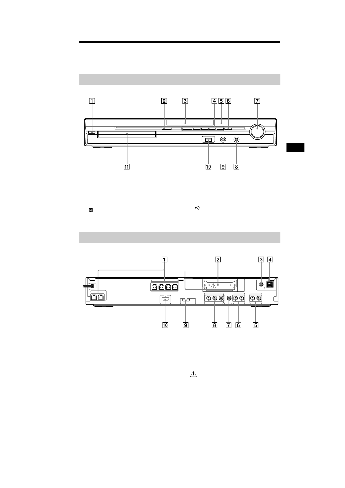
For more inform at ion, refer to t he pages ind ic at ed in paren theses.
(DZ265K/DZ266K/DZ270K/DZ570K)
Front panel
" / (on/standby) (33, 100)
# " (open/close) (41)
$ Front pan el display (121)
% Play operation buttons (41)
& (remote sensor) (10)
' FUNCTION (36)
( VOLUME control (41)
) MIC2 jack (92)
* AUDIO IN/MIC1/A.CAL MIC jack (27, 33,
90)
+ (USB) port (74)
, Disc tray (41)
Additional Information
119
GB
11
HCD-DZ265K/DZ266K/DZ270K/DZ570K/DZ777K
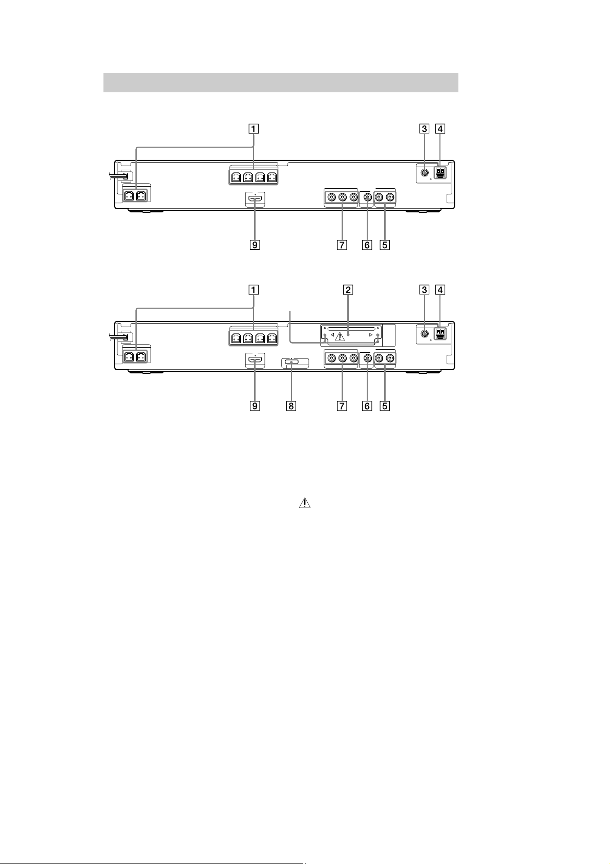
Rear panel
HCD-DZ265K/DZ266K/DZ270K
SPEAKER
FRONTR FRONTL SUR R SUR L
SPEAKER
CENTER SUBWOOFER
HDMI OUT
HCD-DZ570K
SPEAKER
FRONTR FRONTL SUR R SUR L
SPEAKER
CENTER SUBWOOFER
HDMI OUT
" SPEAKER jacks (22)
# EZW-T100 slot (DZ570K only) (27)
$ COAXIAL 75 Ω FM jack (30)
% AM terminal (30)
& TV/VIDEO (AUDIO IN R/L) jacks (24, 27)
' VIDEO OUT jack (24)
B/CBPR/CR
Y
P
COMPONENTVIDEO OUT
VIDEO OUT TV/VIDEO
AUDIO IN
LR
Screws*
EZW-T100
DC5V
DMPORT
0.7A MAX
P
B/CBPR/CR
Y
COMPONENTVIDEO OUT
AUDIO IN
VIDEO OUT TV/VIDEO
LR
( COMPON ENT VIDEO OUT jacks (24)
) DMPORT (DIGITAL MEDIA PORT) jack
(DZ570K only) (27, 82)
* HDMI OUT jack (24)
* CAUTION
Please do not remove the screws before
installing the EZW-T100 (DZ570K only).
ANTENNA
COAXIAL 75
FM
ANTENNA
COAXIAL 75
FM
AM
AM
12
120
GB

HCD-DZ265K/DZ266K/DZ270K/DZ570K/DZ777K
Front panel display
About the indications in the front panel display
" Lights up when the karaoke mode is
on. (92)
# Flashes wh en the sleep t imer is set.
(96)
$ Displays system’s status such as
chapter, title, or track number, time
information, radio frequency, playing
status, decoding mode, etc.
% Lights up when a station is received.
(Radio only) (67)
& Stereo/Monaural effect (Radio only)
(68)
' Lights up when the S-AIR transmitter
(not supplied) is inserted in the unit
and the system transmi ts the sound.
(DZ570Konly) (83)
( Lig hts up when t h e HDMI OUT jack is
correctly connected to HDCP (Highbandwidth Digital Content Protection)
compliant device with HDMI or DVI
(Digital Visual Interface) input. (24)
) Current su rround format (Except for
JPEG image file)
* Lights up when the color system is set
toNTSC.(Asian, Australian,and Middle
Eastern models only)
Lights up when an NTSC disc is
loaded. (Russian models onl y)
+ Lights up during USB r e cor d ing/
copying. (80)
, Lights up whenSuper Audio CD/CD is
loaded. (44)
- Playing status
Additional Information
121
GB
13
HCD-DZ265K/DZ266K/DZ270K/DZ570K/DZ777K
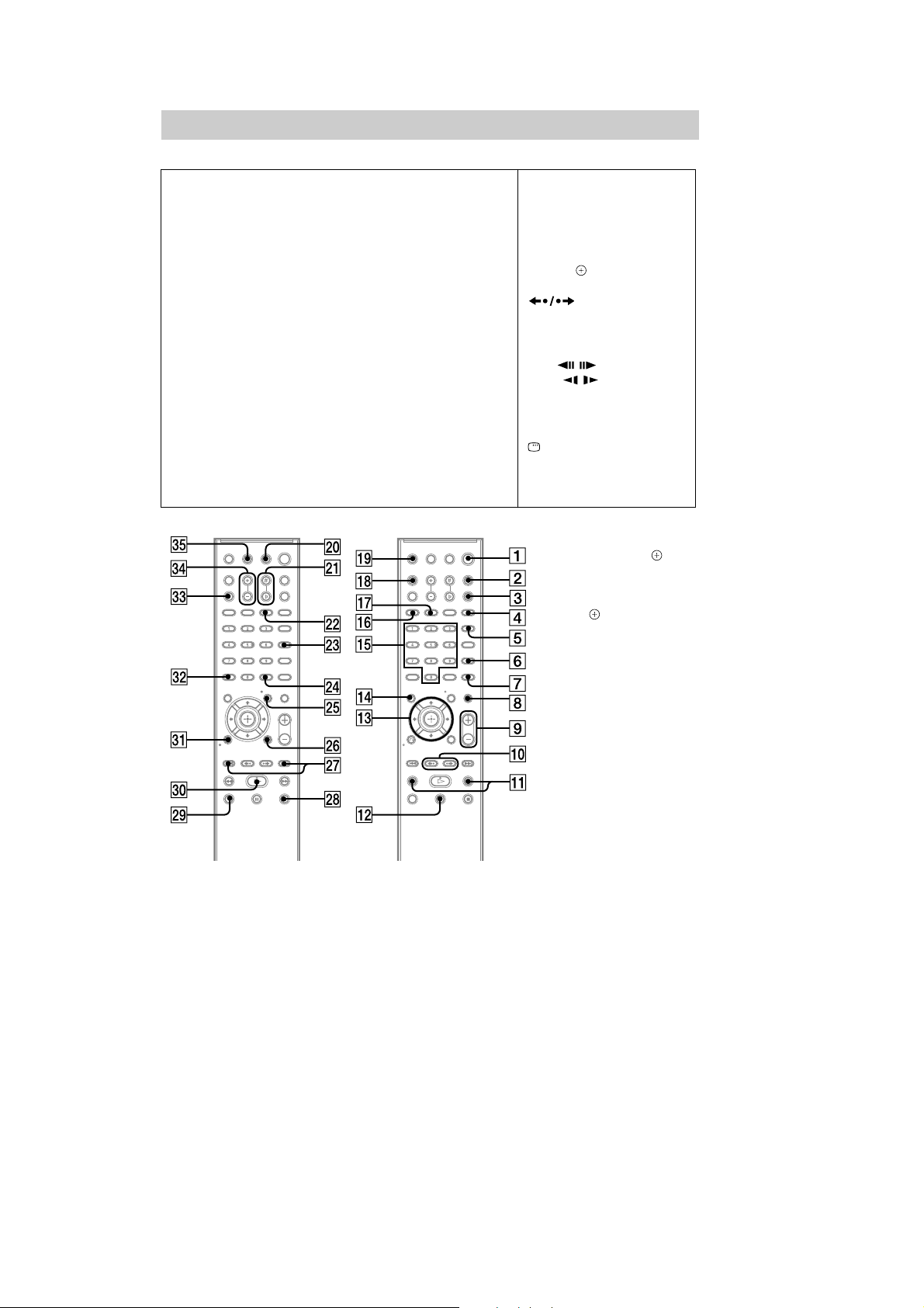
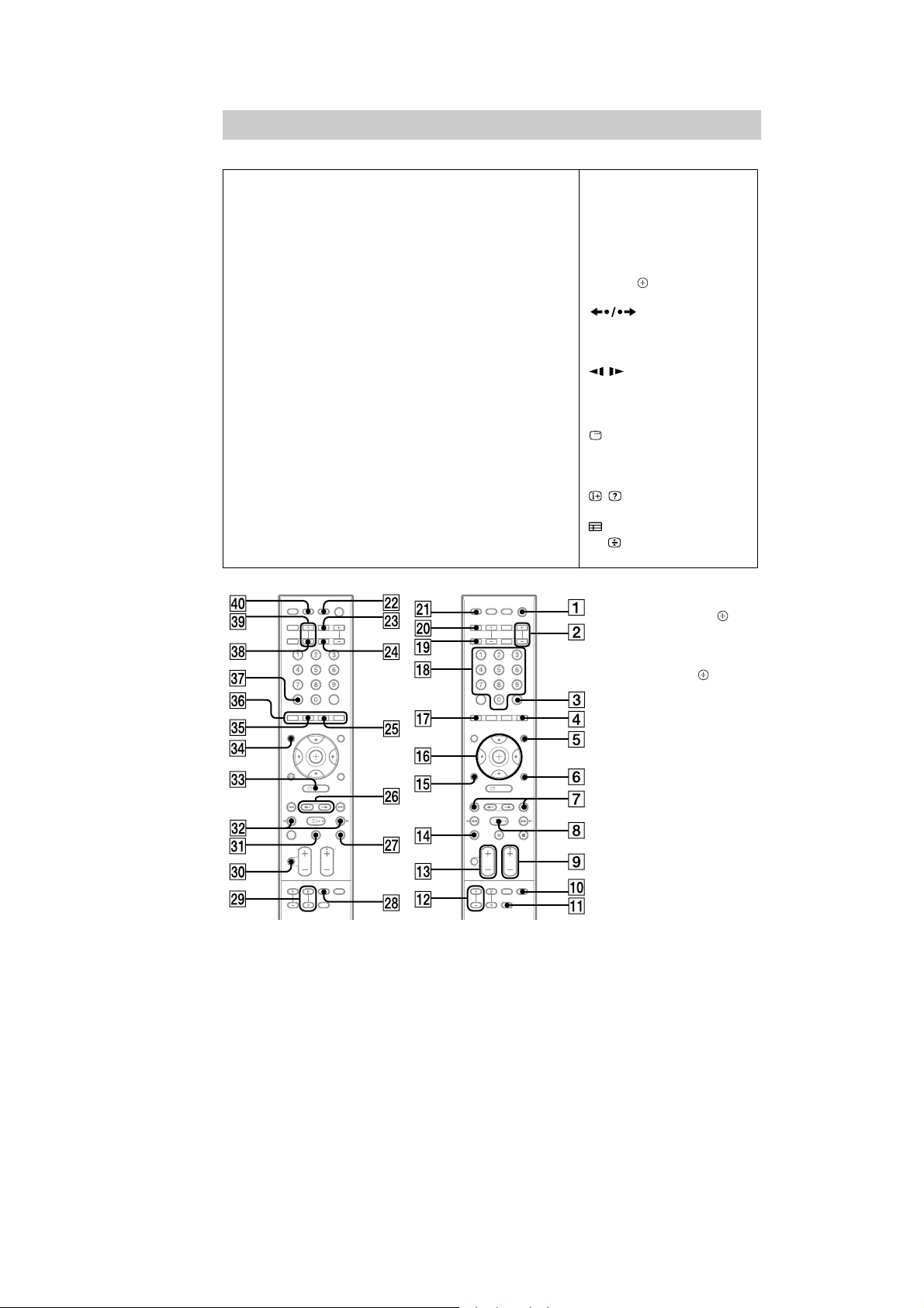
Remote control
Z–NM–A
ANGLE (42)
AUDIO RK (43)
CLEAR FT (46, 58, 68)
D.TUNING XT (68)
DISPLAY (69, 79, 97)
DVD MENU XH (49)
DVD TOP MENU RG (49)
DYNAMIC BASS (96)
1)
ENTER
ECHO RL (92)
FUNCTION (36, 41)
INPUT RI (91)
KARAOKE PON (94)
KEYCON #/
MENU XH (91)
MIC VOL +/– FG (92)
MUTING (41)
XG (32, 33, 44, 46, 67,
89)
XB (93)
NIGHT XE (96)
ONE-TOUCH PLAY FH (72)
PICTURE NAVI RI (51, 76)
PRESET +/– XK (68)
PROG +/– XK (91)
SCORE FE (95)
SOUND MODE (40)
SUBTITLE XT (42)
SYSTEM MENU XG (32, 37, 96,
97)
THEATRE RM (71)
TOOLS XI (91)
TUNING +/– RB (67)
TV XM (91)
VOLUME +/– (41)
SNOITPIRCSEDNOTTUBREDROLACITEBAHPLA
Number buttons RH (45, 67, 91)
</ (on/standby) (32, 33, 41)
TV </ (on/standby) X (91)
$/9/Y/D/ RE (32, 33, 44, 46,
67, 89)
(41)
/ XK (41)
N/. RB (41)
STEP / (41)
SLOW / RB (41)
)(play) F (41)
Y (s
9 (pause) RT (41)
0 RETURN FB (45, 91)
-/-- FT (91)
REPLAY/ADVANCE
t
op) XL (41)
DISPLAY
2)
XI (33, 44, 46, 89)
122
1)
The ENTER button has the
same function as the
button. When you operate
the TV, the ENTER button is
used for selecting a channel,
and the button is used for
selecting menu items
(page 91).
2)
This button is available for
the “DVD,” “USB,” or
“DMPORT*” function.
Depending on the DIGITAL
MEDIA PORT adapter, this
button may not work.
* HCD-DZ570K only
GB
14
HCD-DZ265K/DZ266K/DZ270K/DZ570K/DZ777K
Index to Parts and Control
(DZ777K)
For more inform at ion, refer to t he pages ind ic at ed in parentheses.
Front panel
" / (on/standby) (34, 101)
# " (open/close) (42)
$ Front pan el display (121)
% Play operation buttons (42)
& (remote sensor) (9)
' FUNCTION (37)
( VOLUME control (42)
) MIC2 jack (93)
* AUDIO IN/MIC1/A.CAL MIC jack (30, 34,
90)
+ (USB) port (74)
, Disc tray (42)
Additional Information
Rear panel
SPEAKER
FRONTR FRONTL SUR R SUR L
SPEAKER
CENTER SUBWOOFER
HDMI OUT
" SPEAKER jacks (27)
# EZW-T100 slot (30)
$ COAXIAL 75 Ω FM jack (32)
% AM terminal (32)
& SAT/CABLE (AUDIO IN R/L) jacks (30)
' TV (AUDIO IN R/L) j acks (28)
( VIDEO OUT jack (28)
Screws*
EZW-T100
DC5V
DMPORT
0.7A MAX
B/CBPR/CR
Y
P
COMPONENTVIDEO OUT
VIDEO OUT TV
AUDIO IN
LR
) COMPON ENT VIDEO OUT jacks (28)
* DMPORT (DIGITAL MEDIA P O RT) jack
(30, 82)
+ HDMI O UT jack (28)
* CAUTION
Please do not remove the screws before
installing the EZW -T100.
AUDIO IN LR
SAT/CABLE
ANTENNA
COAXIAL 75
FM
AM
15

HCD-DZ265K/DZ266K/DZ270K/DZ570K/DZ777K
Front panel display
About the indications in the front panel display
" Lights up when the karaoke mode is
on. (93)
# Flashes wh en the sleep t imer is set.
(97)
$ Displays system’s status such as
chapter, title, or track number, time
information, radio frequency, playing
status, decoding mode, etc.
% Ligh t s up when a stat io n is re c e i v e d.
(Radio only) (67)
& Stereo/Monaural effect (Radio only)
(68)
' Lights up when the S-AIR transmitter
(not supplied) is inserted in the unit
and the system transmi ts the sound.
(83)
( Lights up when the HDMI OUT jack is
correctly connected to HDCP (Highbandwidth Digital Content Protection)
compliant device with HDMI o r DVI
(Digital Visual Interface) input. (28)
) Current surround format (Except for
JPEG image file)
* Lights up when the color system is set
toNTSC. (Asian, Australian, and Middle
Eastern models only)
Lights up when an NTSC disc is
loaded. (Russian models onl y)
+ Lights up during USB r e cor ding/
copying. (80)
, Lights up whenSuper Audio CD/CD is
loaded. (45)
- Playing status
Additional Information
16
121
GB
Remote control
ANALOG FL (91)
ANGLE (43)
AUDIO FH (44)
CLEAR FK (47, 59, 68)
D.TUNING XH (68)
DIGITAL XG (91)
DISPLAY RM (69, 79, 98)
DVD M ENU (50)
DVD TOP MENU FG (50)
DYNAMIC BASS XG (97)
ECHO RB (93)
ENTER* (33, 34, 45, 47, 67,
89)
FUNCTION +/– (37, 42)
KARAOKE PON (95)
KEYCON #/
MENU FE (91)
MIC VOL +/– RT (93)
MUTING F (42)
XM (94)
HCD-DZ265K/DZ266K/DZ270K/DZ570K/DZ777K
SNOITPIRCSEDNOTTUBREDROLACITEBAHPLA
Z–NM–A
NIGHT XE (97)
ONE-TOUCH PLAY S (72)
PICTURE NAVI RK (52, 76)
PRESET +/– (68)
PROG +/– (91)
SCORE XL (96)
SLEEP X (97)
SOUND MODE +/– FM (41)
SUBTITLE XH (43)
SYSTEM MENU (33, 38, 97,
98, 83)
THEATRE XB (71)
TOOLS (91)
TUNING +/– FT (67)
TV RG (91)
TV VOL +/– RE (91)
VOLUME +/– RE (42)
Number buttons RL (46, 67, 91)
Colored buttons FI (91)
</ (on/standby) (33, 34, 42)
TV </ (on/standby) XT (91)
$/9/Y/D/
67, 89)
XI (42)
/ (42)
N/. FT (42)
)(
Y (stop) XK (42)
9 (pause) FB (42)
89)
0 RETURN RH (46, 91)
-/-- (91)
/ RM (91)
FK (91)
U/ (91)
D/$ (91)
RI (33, 34, 45, 47,
REPLAY/ADVANCE
/ FT (42)
lay) (42)
p
DISPLAY** FE (34, 45, 47,
FG (91)
122
* The ENTER button has the
same function as the
button. When you operate
the TV, the ENTER button
is used for selecting a
channel, and the button
is used for selecting menu
items (page 91).
**This button is available for
the “DVD,” “USB,” or
“DMPORT” function.
Depending on the
DIGITAL MED IA PORT
adapter, this button may not
work.
GB
17

HCD-DZ265K/DZ266K/DZ270K/DZ570K/DZ777K
SECTION 3
DISASSEMBLY
• This set can be disassembled in the order shown below.
SET
3-1. CASE
(Page 19)
3-2. POWER BOARD
(Page 19)
3-3. FRONT PANEL SECTION
(Page 20)
3-5. DVD MECHANISM DECK
(Page 21)
3-8. TRAY
(Page 22)
3-9. BELT
(Page 23)
3-10. MS-203 BOARD
(Page 23)
3-4. BACK PANEL SECTION
(Page 20)
3-6. MAIN BOARD
(Page 21)
3-11. BASE UNIT
(Page 24)
3-12. OPTICAL PICK-UP
(Page 24)
3-7. IO-COMPONENT BOARD,
SCORE BOARD
(Page 22)
18
HCD-DZ265K/DZ266K/DZ270K/DZ570K/DZ777K
Note: Follow the disassembly procedure in the numerical order given.
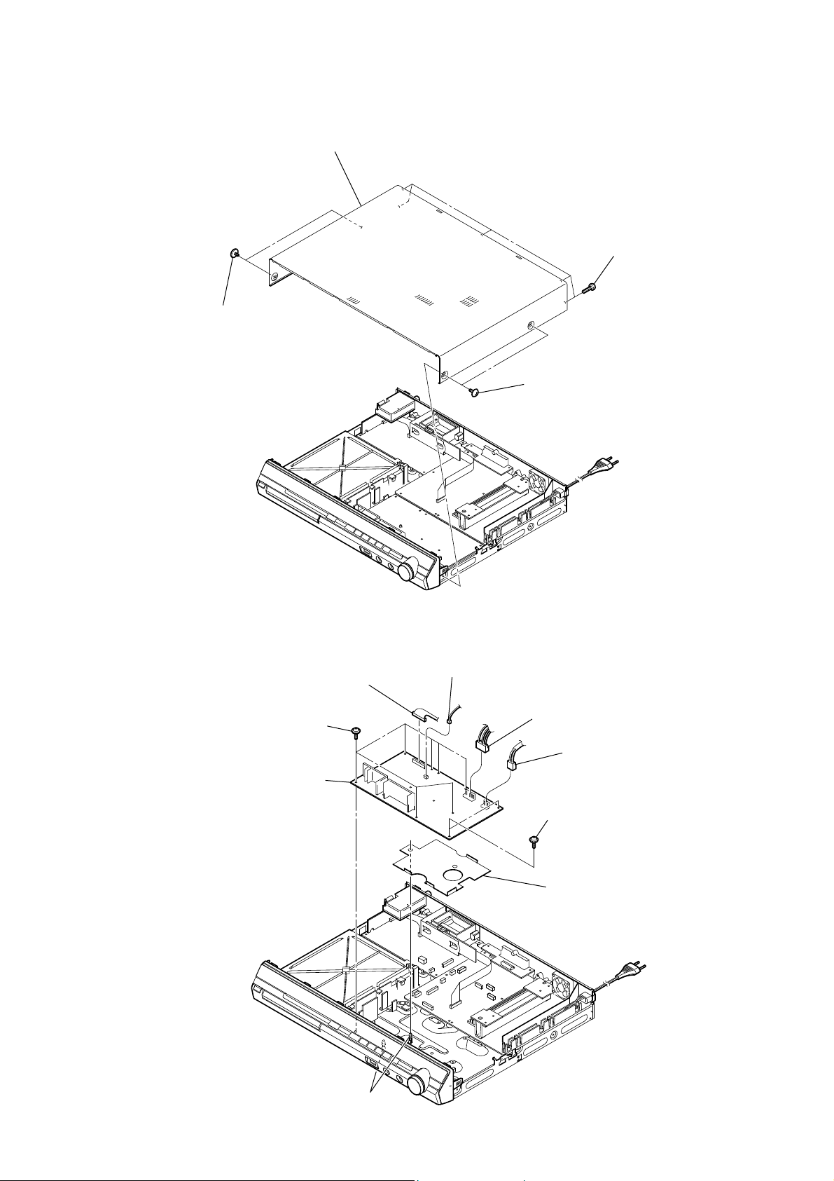
3-1. CASE
case
five screws
(BV/RING)
two screws
(case 3 TP2)
two screws
(case 3 TP2)
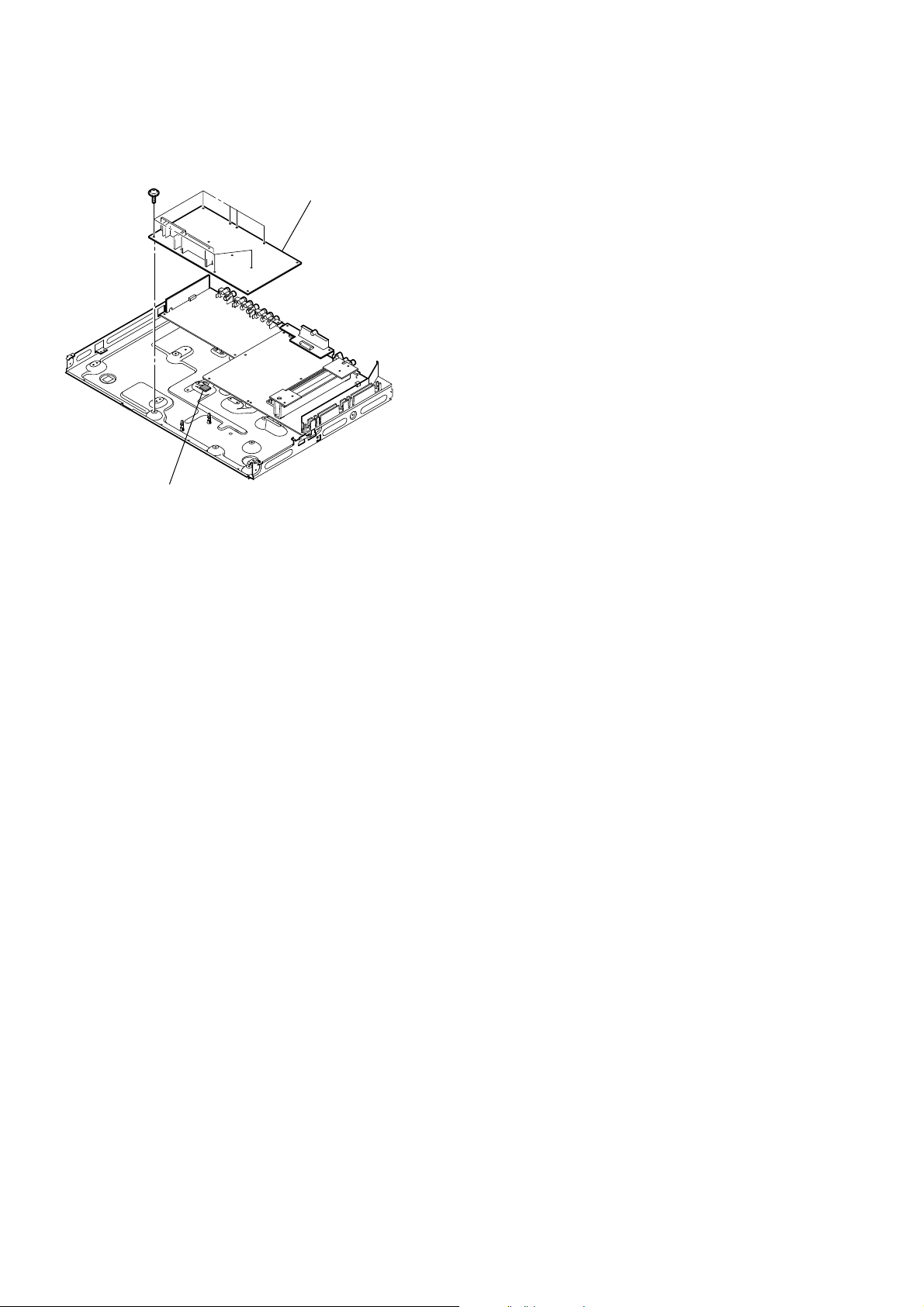
3-2. POWER BOARD
POWER board
CN906 (13P)
seven screws
(+PWH 3 × 8)
CN908 (2P)
CN904 (4P)
CN901 (2P)
two screws
(+PWH 3 × 8)
cover (USB)
two claws
19

HCD-DZ265K/DZ266K/DZ270K/DZ570K/DZ777K
3-3. FRONT PANEL SECTION
claw
loading panel
wire (flat type)(19 core)
(CN502)
two screws
(+BV3 (3-CR))
RB front panel section
CN411 (5P)
claw
five screws
(+BV3 (3-CR))
CN2101 (5P)
label
3-4. BACK PANEL SECTION
wire (flat type) (11 core) (CN414)
(DZ265K/DZ266K)
wire (flat type) (9 core) (CN419)
(DZ270K/DZ570K/DZ777K)
CN111 (2P)
(DZ570K/DZ777K)
RB back panel section
three screws
(+BVTP 3 × 8)
tray
screw
(+BVTP 3 × 8)
screw
(+B 3 × 6)
two screws
(+BVTP 3 × 8)
three screws
(+BVTP 3 × 8)
screw
(+BVTP 3 × 8)
20
CN3000 (2P)
wire (flat type) (17 core) (CN651)
(DZ570K/DZ777K)

3-5. DVD MECHANISM DECK
HCD-DZ265K/DZ266K/DZ270K/DZ570K/DZ777K
screw
(+BV3 (3-CR))
cover (CDM-DSR)
two screws
(+BV3 (3-CR))
DVD mechanism deck
screw
(+BV3 (3-CR))
screw
(+BV3 (3-CR))
screw
(+BV3 (3-CR))
wire (flat type)(5 core)
(CN1202)
CN1201 (6P)
wire (flat type)(24 core)
(CN1101)
3-6. MAIN BOARD
wire (flat type) (17 core) (CN4302) (DZ570K/DZ777K)
wire (flat type) (15 core) (CN4303) (DZ265K/DZ266K/DZ270K)
wire (flat type)(7 core)
(CN701)
wire (flat type) (21 core) (CN601)
(DZ265K/DZ266K)
wire (flat type) (19 core) (CN602)
(DZ270K/DZ570K/DZ777K)
RT six screws
(+BV3 (3-CR))
RE MAIN board
screw
(+BVTP 3 × 12)
two screws
(+BV3 (3-CR))
heat sink section
two screws
(+BV3 (3-CR))
SPEAKER board
CN114 (8P)
two radiation sheet
RB two screws
(+BV3 (3-CR))
21
HCD-DZ265K/DZ266K/DZ270K/DZ570K/DZ777K
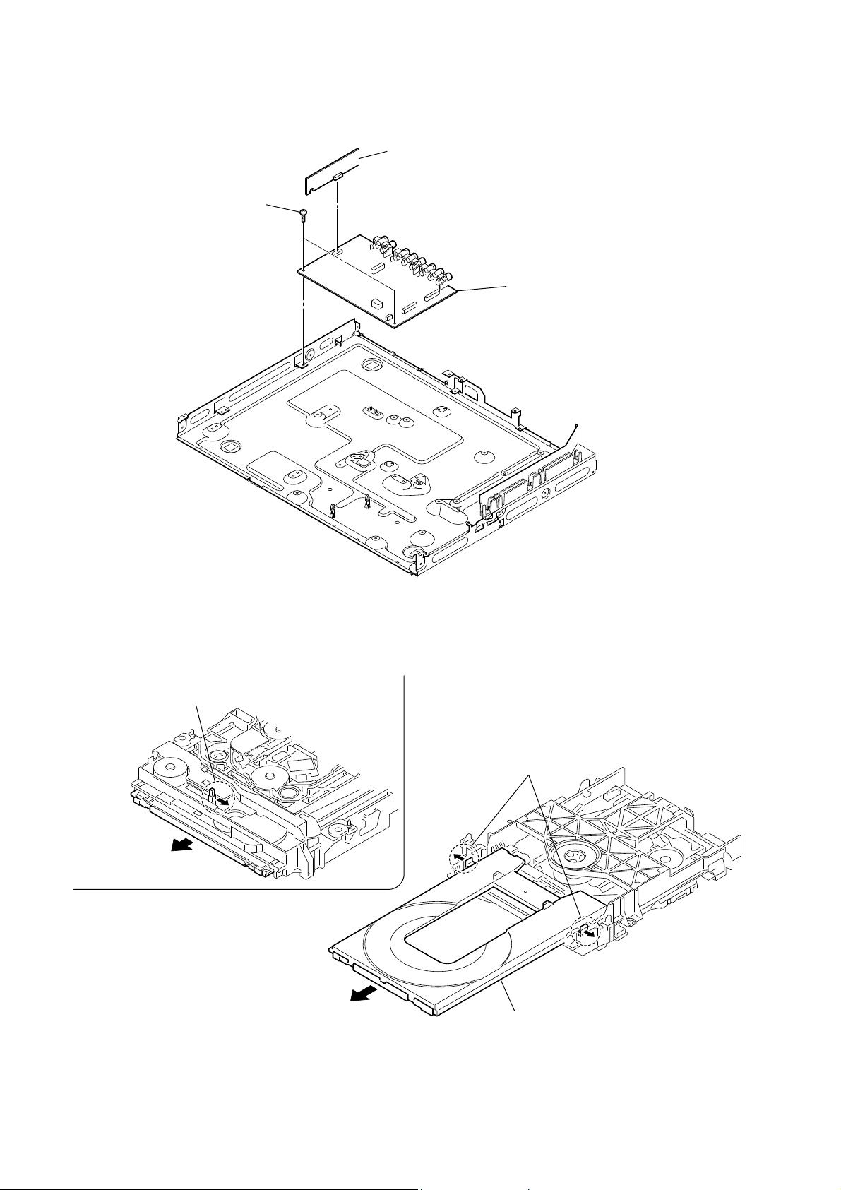
3-7. IO-COMPONENT BOARD, SCORE BOARD
SCORE board
two screws
(+BV3 (3-CR))
I/O COMPONENT board
3-8. TRAY
Move the chuck cam
in the direction of the arrow.
bottom side
two claws
tray
22

3-9. BELT
chuck cam
HCD-DZ265K/DZ266K/DZ270K/DZ570K/DZ777K
belt
3-10. MS-203 BOARD
two claws
MS-203 board
DC motor
three claws
screw
(M 1.7 × 2.5)
23

HCD-DZ265K/DZ266K/DZ270K/DZ570K/DZ777K
3-11. BASE UNIT
chuck cam
two claws
two claws
base unit
3-12. OPTICAL PICK-UP
two insulator screws
FFC holder
two insulator screws
two claws
two insulators
optical pick-up
two insulators
24

HCD-DZ265K/DZ266K/DZ270K/DZ570K/DZ777K
SECTION 4
TEST MODE
Note: Incorrect operations may be performed if the test mode is not
entered properly.
In this case, press the [?/1] button to turn the power off, and
retry to enter the test mode.
1. Cold Reset
• The cold reset clears all data including preset data stored in the
RAM to initial conditions. Execute this mode when returning
the set to the customers.
Procedure:
1. Press the [
2. Press three buttons [x], [A] and [
] button to turn the power on.
?/1
?/1
] simultaneously.
3. When this button is operated, display as “COLD RESET” for
a while and all of the settings are reset.
2. Panel Test Mode
• This mode is used to check the software version, FL and
KEY.
2-1. Display Test Mode
Procedure:
1. Press the [
2. Press three buttons [
] button to turn the power on.
?/1
], [.] and [A] simultaneously.
X
3. When the display test mode is activated, all segments are turned
on.
4. To exit from this mode, press three buttons [X], [.] and [A]
simultaneously.
2-2. Version Test Mode
Procedure:
1. When the display test mode is activated, press the [.] button
and the message “DSR2K–” (DZ265K), “DSR2K+” (DZ266K),
“DSR2K” (DZ270K), “DSR4K” (DZ570K), “DSR7K” (DZ777K)
are displayed, the version test mode is activated.
2. Whenever the [.] button is pressed, the display changes in
the following order.
“DSR7K” (Model name) U“ASIA2*1” (Destination) U
UMC V ersion U SYS V ersion UUI Version U
UDVD V ersion UST V ersion U T A V ersion U
UDSP V ersion UTM V ersion UMM Version U
U CLA Version UCEC Version USAIR Version
*1: ASIA2 changes depending on destination.
3. Press the [>] button and the date of the software production
is displayed.
4. Press the [>] button again and the version is displayed.
5. To exit from this mode, press three buttons [X], [.] and [A]
simultaneously.
2-3. Key Test Mode
Procedure:
1. When the display test mode is activated, press the [H] button,
to select the key test mode.
2. To enter the KEY test mode, the fl uorescent indicator displays
“K0 V0”. Each time an another button is pressed, “KEY” value
increases. However, once a button is pressed, it is no longer
taken into account. When all keys are pressed correctly, “K8
V0” is displayed.
3. When the [VOLUME] control is turned in the direction of (+),
“V0” is changed to “V1”, then ... “V9”.
When the [VOLUME] control is turned in the direction of (–),
“V0” is changed to “V9”, then ... “V1”.
4. To exit from this mode, press three buttons [X], [.] and [A]
simultaneously.
3. Disc Tray Lock
The disc tray lock function for the antitheft of an demonstration
disc in the store is equipped.
Setting Procedure :
1. Press the [
] button to turn the set on.
?/1
2. Press the [FUNCTION] button to set DVD function.
3. Insert a disc.
4. Press the [x] button and the [A] button simultaneously for fi ve
seconds.
5. The message “LOCKED” is displayed and the tray is locked.
Releasing Procedure :
1. Press the [x] button and the [A] button simultaneously for fi ve
seconds again.
2. The message “UNLOCKED” is displayed and the tray is
unlocked.
Note: When “LOCKED” is displayed, the tray lock is not released by
turning power on/off with the [?/1] button.
4. DVD Ship Mode
Use this mode when returning the set to the customer after repair.
Procedure:
1. Press the [
] button to turn the set on.
?/1
2. Press the [FUNCTION] button to set the function “DVD”.
3. Remove all Discs, and then press two buttons [H] and [
?/1
simultaneously.
4. After a message “MECHA LOCK” h “PULL PLUG” is
displayed on the fl uorescent indicator tube, pull out the AC
plug.
5. To exit from this mode, press the [
] button to turn the set
?/1
on.
5. AM Step Change (Except RU models)
• A step of AM channels can be changed over between 9 kHz
and 10 kHz.
Procedure:
1. Press the [
] button to turn the set ON.
?/1
2. Select the function “TUNER”, and press [FUNCTION] button
to select the BAND “AM”.
3. Press the [
4. Press two buttons [>] and [
] button to turn the set OFF.
?/1
?/1
] simultaneously, and the
display of fl uorescent indicator tube changes to “AM 9k STEP”
or “AM 10k STEP”, and thus the channel step is changed
over.
6. Product Out
This mode moves the optical pick-up to the position durable to
vibration and clears all data including preset data stored in the
RAM to initial conditions. Use this mode when returning the set to
the customer after repair.
Procedure:
1. Press the [
] button to turn the power on.
?/1
2. Press the [FUNCTION] button to set the function “DVD”.
3. Remove all discs, and then press three buttons [>], [A] and
[
] simultaneously.
?/1
4. After the “STANDBY” blinking display fi nishes, the message
“MECHA LOCK” h “PULL PLUG” is displayed on the
fl uorescent indicator tube disconnect the AC power plug, then
the ship mode is set.
]
25
HCD-DZ265K/DZ266K/DZ270K/DZ570K/DZ777K
DVD SECTION
7-1. GENERAL DESCRIPTION
The IOP measurement allows you to make diagnosis and
adjustment simply by using the remote commander and monitor
TV. The instructions, diagnosis results, etc. are given on the onscreen display (OSD).
Be sure to execute the IOP measurement when a BU (Base Unit)
is replaced.
7-2. HOW TO ENTER TEST MODE
While pressing the [
] and [A] buttons simultaneously, turn
x
[VOLUME] control in the direction of (+) with the DVD player
in power on.
The Test Mode starts, displayed “SERVICE IN” on this model
display then the menu shown below will be displayed on the TV
screen.
* The display of the “Model Name” of the “Remocon Diagnosis
Menu” change with the model and the destination. Refer to
below on the model name.
DZ265K : DSR2K–
DZ266K : DSR2K+
DZ270K : DSR2K
DZ570K : DSR4K
DZ777K : DSR7K
Remocon Diagnosis Menu
0. External Chip Check
1. Servo Parameter Check
2. Drive Manual Operation
3. Emergency History
4. Version Information
(2) Select “2. Drive Manual Operation” by pressing the [2] button
on the remote commander. The screen will appear as shown.
Drive Manual Operation
1. Servo Control
2. Track/Layer Jump
3. Manual Adjustment
4. Tray Aging Mode
5. MIRR time adjust
0. Return to Top Menu
(3) Select “3. Manual Adjustment” by pressing the [3] button on
the remote commander. The screen will appear as shown.
Manual Adjust
1. Track Balance Adjust:
2. Track Gain Adjust:
3. Focus Balance Adjust:
4. Focus Gain Adjust:
5. Eq Boost Adjust:
6. Iop:
7. TRV. Level:
8. S curve(FE) Level:
9. RFL(PI) Level:
0. MIRR Time:
0P Change Value
[RETURN] Return to previous menu
(4) Select “6. IOP” by pressing the [6] button on the remote
commander.
(5) Wait until a hexadecimal number appear.
1
Model Name
IF-con : Ver. XX.XX (XXXX)
Syscon : Ver. X.XXX
*1: Changes depending on destination
: DSR7K_XX
*
The menu above is the Remocon Diagnosis Menu screen which
consists of fi ve main functions. At the bottom of the menu screen,
the model name and IF-con version. To exit from the Test Mode,
press the power button on the remote commander.
7-3. EXECUTING IOP MEASUREMENT
In order to execute IOP measurement, the following standard
procedures must be followed.
(1) In power on, while pressing the [x] and [A] buttons
simultaneously, turn the [VOLUME] control in the direction
of (+).
Remocon Diagnosis Menu
0. External Chip Check
1. Servo Parameter Check
2. Drive Manual Operation
3. Emergency History
4. Version Information
1
Model Name
IF-con
Syscon
*1: Changes depending on destination
: DSR7K_XX
: Ver. XX.XX (XXXX)
: Ver. X.XXX
*
Manual Adjust
1. Track Balance Adjust:
2. Track Gain Adjust:
3. Focus Balance Adjust:
4. Focus Gain Adjust:
5. Eq Boost Adjust:
6. Iop. 4D:
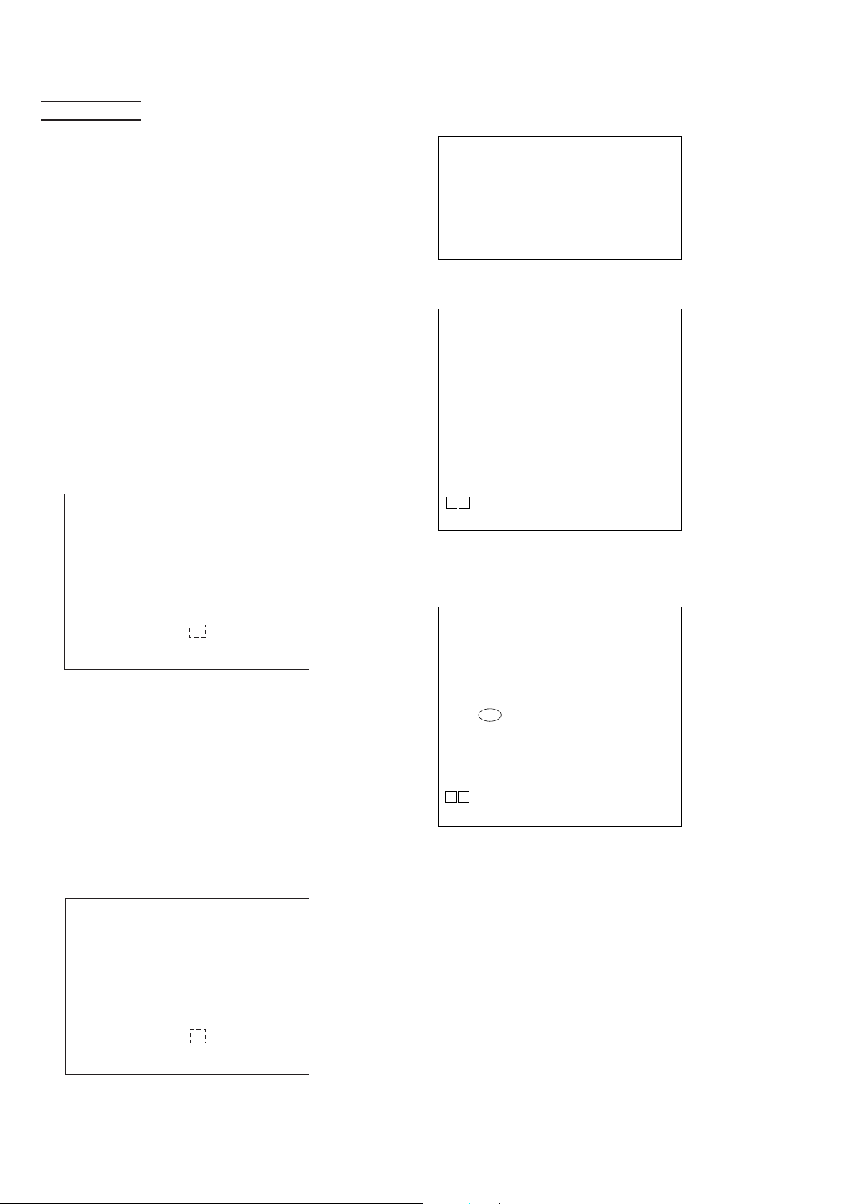
7. TRV. Level:
8. S curve(FE) Level:
9. RFL(PI) Level:
0. MIRR Time:
0P Change Value
[RETURN] Return to previous menu
(6) Convert each data from hexadecimal to decimal using
conversion table.
(7) Please fi nd the label on the rear of the BU (Base Unit).
The default IOP value is written in the label.
(8) Subtract between these two values.
(9) If the remainder is smaller than 93 (decimal), then it is OK.
However if the value is higher than 93, then the BU is defective
and need to be change.
(10) Press the [RETURN] button on the remote commander to
return back to previous menu.
(11) Press the [0] button on the remote commander to return to T op
Menu.
26

HCD-DZ265K/DZ266K/DZ270K/DZ570K/DZ777K
7-4. EMERGENCY HISTORY
To check the emergency history, please follow the following
procedure.
(1) From the Top Menu of Remocon Diagnosis Menu, select “3.
Emergency History Check” by pressing the [3] button on the
remote commander. The following screen appears on the onscreen display.
Emg. History Check
Laser Hours CD 999h 59min
01. 01 05 04 04
00 00 00 00 00 00 23 45
02. 02 02 01 01 00 A9 4B 00
00 00 00 00 00 00 23 45
[Next] Next Page [Prev] Prev Page
[O] Return to Top Menu
DVD 999h 59min
00 92 46 00
(2) You can check the total time when the laser is turned on during
playback of DVD and CD from the above menu. The maximum
time, which can be displayed are 999h 59min.
(3) You can check the error code of latest 10 emergency history
from the above menu. To view the previous or next page of
emergency history, press [.] or [>] button on the remote
commander. The error code consists of the following three
blocks. The fi rst block indicates the error code. The second
block indicates the parameter and the third block indicates the
time of error code as shown below.
• Error Code
Emg. History Check
Laser Hours CD 999h 59min
*1 *2
01. 01 05 04 04
00 00 00 00 00 00 23 45
02. 02 02 01 01 00 A9 4B 00
00 00 00 00 00 00 23 45
[Next] Next Page [Prev] Prev Page
[O] Return to Top Menu
DVD 999h 59min
00 92 46 00
*3
*1 : Error Code
*2 : Parameter of error code
*3 : Time of error code
60: Focus on error
61: Seek fail error
62: Read Q data/ID error
70: Lead in data read fail
71: TOC read time out (CD)
80: Can’t buffering
81: Unknown media type
7-4-1. Clear the Laser Hour
Press [
DISPLAY] button and then press [CLEAR] button on
the remote commander. The data for both CD and DVD data are
reset.
Emg. History Check
Laser Hours CD 0h 0min
01. 01 05 04 04
00 00 00 00 00 00 23 45
02. 02 02 01 01 00 A9 4B 00
00 00 00 00 00 00 23 45
[Next] Next Page [Prev] Prev Page
[O] Return to Top Menu
DVD 0h 0min
00 92 46 00
7-4-2. Clear the Emergency History
Press [DVD TOP MENU] button and then press [CLEAR] button
on the remote commander. The error code for all emer gency history
would be reset.
Emg. History Check
Laser Hours CD 999h 59min
01. 00 00 00 00
00 00 00 00 00 00 00 00
02. 00 00 00 00 00 00 00 00
00 00 00 00 00 00 00 00
[Next] Next Page [Prev] Prev Page
[O] Return to Top Menu
DVD 999h 59min
00 00 00 00
7-4-3. Clear the Initialize Setup Data
Press [DVD MENU] button and then press [CLEAR] button on the
remote commander.
Emg. History Check
The meaning of error code is as below:
01: Communication error (No reply from syscon)
02: Syscon hung up
03: Power OFF request when syscon hung up
19: Thermal shutdown
24: MoveSledHome error
25: Mechanical move error (5 Changer)
26: Mechanical move stack error
30: DC motor adjustment error
31: DPD offset adjustment error
32: TE balance adjustment error
33: TE sensor adjustment error
34: TE loop gain adjustment error
35: FE loop gain adjustment error
36: Bad jitter after adjustment
40: Focus NG
42: Focus layer jump NG
52: Open kick spindle error
51: Spindle stop error
Laser Hours
[Next] Next Page [Prev] Prev Page
[O] Return to Top Menu
CD 999h 59min
DVD 999h 59min
initialize setup data...
27
HCD-DZ265K/DZ266K/DZ270K/DZ570K/DZ777K
7-4-4. Return to the Top Menu of Remocon Diagnosis
Menu
Press [0] button on the remote commander.
• Check Version Information
To check the version information, please follow the following
procedure.
(1) From the Top Menu of Remocon Diagnosis Menu, select “4.
Version Information” by pressing the [4] button on the remote
commander. The following screen appears on the on-screen
display.
Version information
Firm (Main) : Ver. xxxxx
Firm (Sub) : xxxxx
RISC : xxxxx
8032 : xxxxx
Audio DSP : xxxxx
Servo DSP : xxxxx
[O] Return to Top Menu
To return to the Top Menu of Remocon Diagnosis Menu, press
[0] button on the remote commander.
8. DEMO PLAY OUT
It is a mode to release the demonstration reproduct by the dedicated
demonstration disc.
1. During playback the DEMO Disc, press the [x] and [H]
buttons for fi ve seconds simultaneously.
2. The message “DEMO OFF” is displayed, a mode to reproduct
the demonstration is released.
9. DIGITAL MEDIA PORT TEST
1. Connect the DMPORT CHECK JIG (P/N: J-2501-309-A) with
the terminal DMPORT.
2. Press the [
] button to turn the power on.
?/1
3. Confi rm that both LEDs of the DMPORT confi rmation JIG
lights. (Confi rmation the power supply line.)
4. Set the [FUNCTION] button with “DMPORT” on this model.
5. Press the [X], [.] buttons and turn the [VOLUME] control
in the direction of (+) simultaneously, the DMPORT test mode
is activated.
6. It is confi rmed that “DMPORT OK” is displayed on this set
display. (Confi rmation of communication line)
7. To a pin jack of the DMPORT confi rmation JIG input
information relevant to audio signal (sine-wave 1.0Vrms) and
composite video signal (white 100% 1.0Vp-p, color bar, etc.)
8. Confi rm the output of speakers and monitor TV. (Confi rmation
of analog signal)
9. To exit from this mode, press the [X], [.] buttons and turn
the [VOLUME] control in the direction of (+).
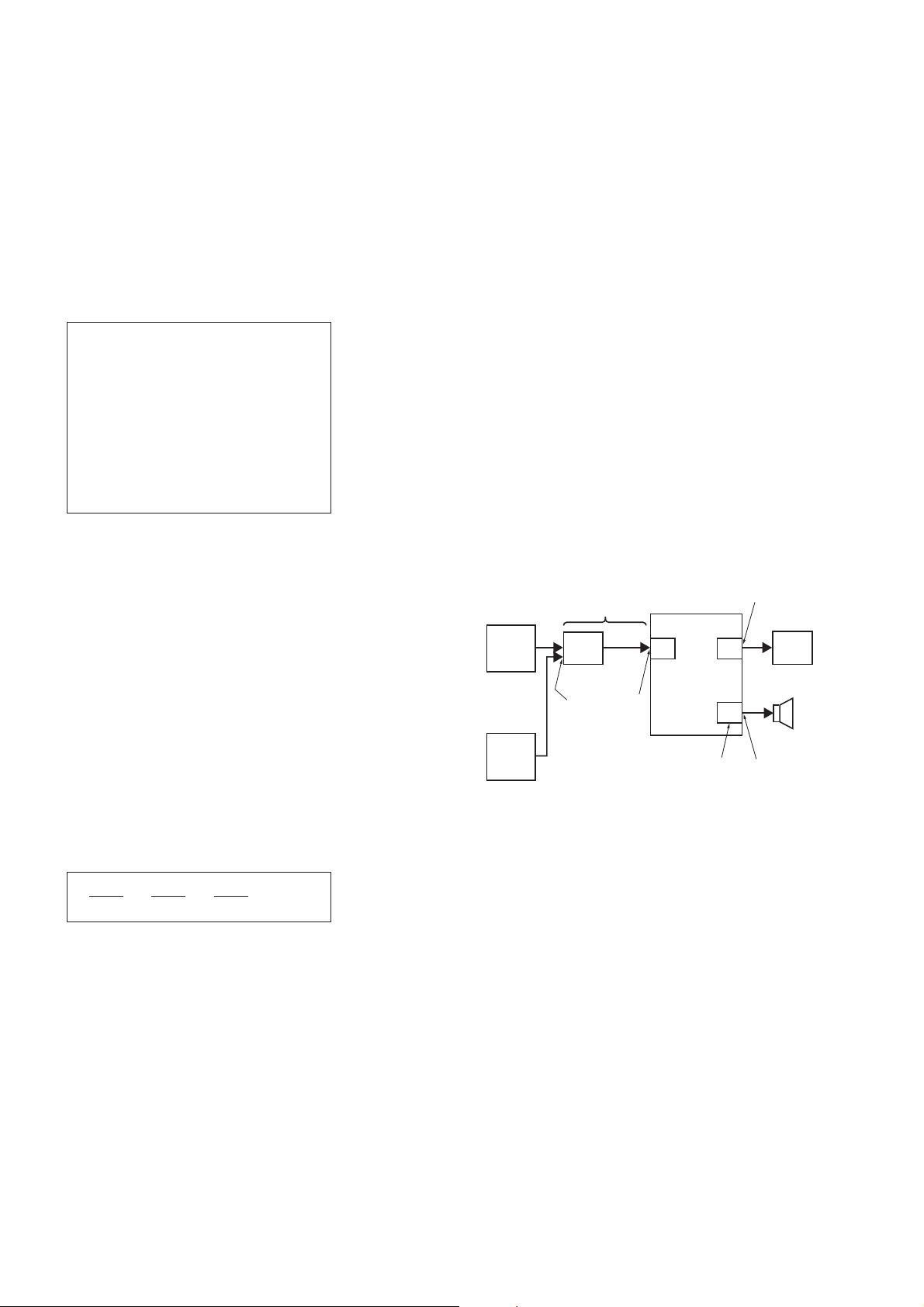
7-5. AUTOMATIC ACOUSTIC FIELD CALIBRATION
MICROPHONE TEST MODE
Procedure:
1. Press the [
] button to turn the power on.
?/1
2. Press the [FUNCTION] button to set the function “ DVD”.
3. Insert ECM-AC2 supplied as an accessory into the AUDIO IN/
A.CAL MIC jack.
4. While pressing the [X] and [A] buttons simultaneously, turn
the [VOLUME] control in the direction of (+).
5. Confi rm that the following are shown on the display panel.
1 The JACK inserted/non-inserted detection display and the
STEREO/MONO detection display.
2 Presence of DIGITAL voice input to the microcomputer.
(OK: input, NG: no input)
3 The value of the MIC input to the microcomputer. (shown
“255h”)
“NON” : Not detected
“ST” : STEREO
“MN” : MONO
OK : input
NG : no input
VIDEO
AUDIO
color pattern
generator
AF oscillator
DMPORT
CHECK JIG
(P/N: J-2501-309-A)
J001 7
CN204
SET
MAIN
board
IO-COMPONENT
SPEAKER
board
J404
TV
board
FL speaker,
FR speaker
TB100
0-255 (Changes in real time)
6. To exit from this mode, press the [
] and [A] buttons simulta-
X
neously, turn the [VOLUME] control in the direction of (+).
28

HCD-DZ265K/DZ266K/DZ270K/DZ570K/DZ777K
10. PROTECTION FACTOR (SD DETECTION/
DC DETECTION) IDENTIFICATION TEST MODE
When an error is detected, the FL tube alternately displays
“PROTECTOR h PUSH POWER”.
r Press the [
* Buttons other than the [
“STANDBY” blinks three times on the FL tube.
r
The protection release state (POWER OFF) is established.
(No FL tube display)
r Press the [
The power to the system turns on, and the normal operation is
established. (Restore)
During the protection state:
1. If the AC plug is connected or disconnected during the
protection state, the protection state is released, and the
normal operation is established. (The protection state is not
maintained.)
2. The protection factor is displayed by pressing the
[FUNCTION], [A] and [>] buttons at the same time during
the protection state
(during the “PROTECTOR h PUSH POWER” display).
k When SD is detected: Repeats
“SD DETECT h PROTECTOR”.
k When DC is detected: Repeats
“DC DETECT h PROTECTOR”.
] button.
?/1
] button two times.
?/1
] button are invalid.
?/1
PL: SD detection
When the “L” output from the SD (shutdown) port on the
S-MASTER POWER Driver Shutdown and voltage descent
(15V or less) of 30V power supply (PVDD) are detected.
DC detection
When the “L” output from the power/speaker error detection
circuit (DC detection port) is detected for two seconds
continually, the power system other than that of the FL tube
is turned off, and the protection state is established.
29
 Loading...