

SONY HCDDX60AV Service Manual
HCD-DX60AV/RG70AV
SERVICE MANUAL
Ver 1.2 2003.07
• HCD-DX60AV/RG70AV is the tuner,
deck, CD and amplifier section in MHCDX60AV/RG70AV.
Dolby noise reduction manufactured under license
from Dolby Laboratories Licensing Corporation.
“DOLBY” and the double-D symbol ; are trademarks of Dolby Laboratories Licensing Corporation.
CD
Section
Tape deck
Section
US Model
AEP Model
HCD-RG70AV
E Model
HCD-DX60AV
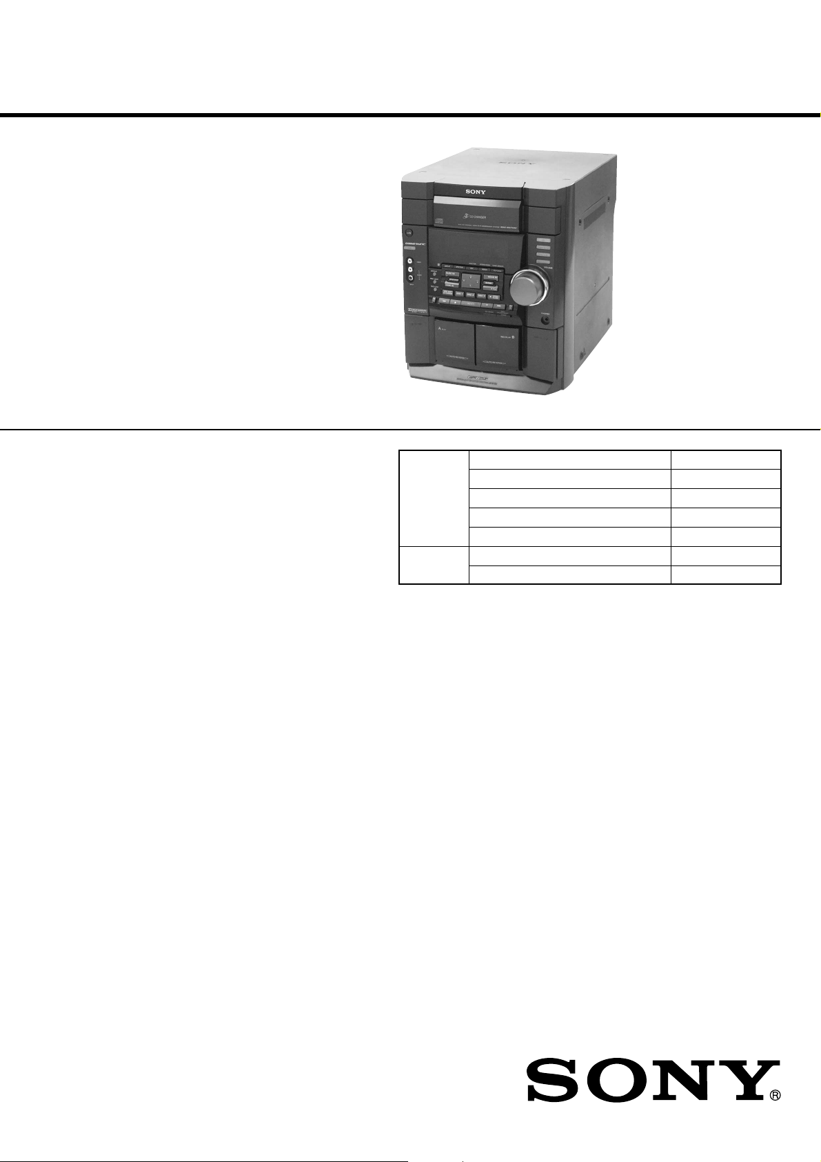
Photo: HCD-RG70AV
Model Name Using Similar Mechanism HCD-DX90
CD Mechanism Type CDM58B-K6BD38
Base Unit Name BU-K6BD38
Optical Pick-up Block Name KSM-213DCP
Optical Pick-up Name KSS-213D
Model Name Using Similar Mechanism NEW
Tape Transport Mechanism T ype CWL44RR-31
SPECIFICATIONS
AUDIO POWER SPECIFICATIONS:
(HCD-RG70AV US model only)
POWER OUTPUT AND TOTAL
HARMONIC DISTORTION:
with 6 ohm loads both channels driven, from
120 – 10,000 Hz; rates 60 watts per channel
minimum RMS power, with no more than 10%
total harmonic distortion from 250 milliwatts to
rated output.
Amplifier section
North American model:
HCD-RG70AV
Front speaker:
Continuous RMS power output (reference)
Total harmonic distortion less than 0.07%
Center speaker:
Continuous RMS power output (reference)
Rear speaker:
Continuous RMS power output (reference)
60 + 60 watts
(6 ohms at 1 kHz,
10% THD)
(6 ohms at 1 kHz,
30 watts)
40 watts
(6 ohms at 1 kHz,
10% THD)
40 + 40 watts
(6 ohms at 1 kHz,
10% THD)
European model:
HCD-RG70AV
Front speaker:
DIN power output (rated) 40 + 40 watts
Continuous RMS power output (reference)
Music power output (reference)
Center speaker:
DIN power output (rated) 25 watts
Continuous RMS power output (reference)
Music power output (reference)
Rear speaker:
DIN power output (rated) 25 + 25 watts
Continuous RMS power output (reference)
Music power output (reference)
(6 ohms at 1 kHz, DIN)
50 + 50 watts (6 ohms at
1 kHz, 10% THD)
95 + 95 watts (6 ohms at 1
kHz, 10% THD)
(6 ohms at 1 kHz, DIN)
35 watts (6 ohms at 1 kHz,
10% THD)
65 watts (6 ohms at 1 kHz,
10% THD)
(6 ohms at 1 kHz, DIN)
35 + 35 watts (6 ohms at
1 kHz, 10% THD)
65 + 65 watts (6 ohms at 1
kHz, 10% THD)
– Continued on next page –
MINI HI-FI COMPONENT SYSTEM
9-873-839-13 Sony Corporation
2003G05-1 Home Audio Company
C 2003.07 Published by Sony Engineering Corporation

HCD-DX60AV/RG70AV
p
Mexican model:
HCD-DX60AV
Front speaker:
DIN power output (rated) 45 + 45 watts
Continuous RMS power output (reference)
Center speaker:
DIN power output (rated) 30 watts
Continuous RMS power output (reference)
Rear speaker:
DIN power output (rated) 30 + 30 watts
Continuous RMS power output (reference)
Inputs
MD/VIDEO IN (phono jacks):
DVD INPUT:
FRONT IN (phono jacks): voltage 450 mV,
REAR IN (phono jacks): voltage 450 mV,
CENTER IN (phono jacks):
WOOFER IN (phono jacks):
Outputs
PHONES (stereo mini jack):
FRONT SPEAKER: accepts impedance of 6 to
REAR SPEAKER: accepts impedance of 6 to
CENTER SPEAKER: accepts impedance of 6 to
WOOFER: voltage 1 V, impedance
(6 ohms at 1 kHz, DIN)
60 + 60 watts
(6 ohms at 1 kHz, 10%
THD)
(6 ohms at 1 kHz, DIN)
40 watts
(8 ohms at 1 kHz, 10%
THD)
(6 ohms at 1 kHz, DIN)
40 + 40 watts
(6 ohms at 1 kHz, 10%
THD)
voltage 250/450 mV,
impedance 47 kilohms
impedance 47 kilohms
impedance 47 kilohms
voltage 450 mV,
impedance 47 kilohms
voltage 450 mV,
impedance 47 kilohms
accepts headphones of 8
ohms or more
16 ohms
16 ohms
16 ohms
1 kilohms
CD player section
System Compact disc and digital
Laser Semiconductor laser
Frequency response 2 Hz – 20 kHz (±0.5 dB)
Wavelength 780 – 790 nm
Signal-to-noise ratio More than 90 dB
Dynamic range More than 90 dB
CD OPTICAL DIGITAL OUT
(Square optical connector jack, rear panel)
Wavelength 660 nm
ut Level –18 dBm
Out
audio system
(λ=780 nm)
Emission duration:
continuous
Tape deck section
Recording system 4-track 2-channel stereo
Frequency response 40 – 13,000 Hz (±3 dB),
Wow and flutter ±0.2% W.Peak (IEC)
using Sony TYPE I
cassettes
0.35% W.RMS (NAB)
±0.3% W.Peak (DIN)
Tuner section
FM stereo, FM/AM superheterodyne tuner
FM tuner section
Tuning range 87.5 – 108.0 MHz
Antenna FM lead antenna
Antenna terminals 75 ohm unbalanced
Intermediate frequency 10.7 MHz
AM tuner section
Tuning range
Pan-American model: 530 – 1,710 kHz (with the
European model: 531 – 1,602 kHz (with the
Antenna AM loop antenna
Antenna terminals External antenna terminal
Intermediate frequency 450 kHz
interval set at 10 kHz)
531 – 1,710 kHz (with the
interval set at 9 kHz)
interval set at 9 kHz)
General
Power requirements
North American model: 120 V AC, 60 Hz
European model: 230 V AC, 50/60 Hz
Mexican model: 120 V AC, 60Hz
Power consumption
North American model: 170 watts
European model: 150 watts
Mexican model: 150 watts
Dimensions (w/h/d)
Mass
North American model: Approx. 9.0 kg
European model: Approx. 10.0 kg
Mexican model: Approx. 9.5 kg
Supplied accessories: AM loop antenna (1)
Design and specifications are subject to change
without notice.
0.5 watts (at the Power
Saving Mode)
Approx. 280 × 325 × 421 mm
Remote commander (1)
Batteries (2)
FM lead antenna (1)
Front speaker pads (8)
2
HCD-DX60AV/RG70AV
1.5 k
Ω
0.15 µF
AC
voltmeter
(0.75 V)
To Exposed Metal
Parts on Set
Earth Ground
NOTES ON HANDLING THE OPTICAL PICK-UP
BLOCK OR BASE UNIT
The laser diode in the optical pick-up block may suffer electrostatic break-down because of the potential difference generated
by the charged electrostatic load, etc. on clothing and the human
body.
During repair, pay attention to electrostatic break-down and also
use the procedure in the printed matter which is included in the
repair parts.
The flexible board is easily damaged and should be handled with
care.
NOTES ON LASER DIODE EMISSION CHECK
The laser beam on this model is concentrated so as to be focused
on the disc reflective surface by the objective lens in the optical
pick-up block. Therefore, when checking the laser diode emission, observe from more than 30 cm away from the objecti ve lens.
Laser component in this product is capable
of emitting radiation exceeding the limit for
Class 1.
SAFETY CHECK-OUT
After correcting the original service problem, perform the following safety check before releasing the set to the customer:
Check the antenna terminals, metal trim, “metallized” knobs,
screws, and all other exposed metal parts for AC leakage.
Check leakage as described below.
LEAKAGE TEST
The AC leakage from any exposed metal part to earth ground and
from all exposed metal parts to any exposed metal part having a
return to chassis, must not exceed 0.5 mA (500 microamperes.).
Leakage current can be measured by any one of three methods.
1. A commercial leakage tester, such as the Simpson 229 or RCA
WT -540A. Follo w the manufacturers’ instructions to use these
instruments.
2. A battery-operated AC milliammeter. The Data Precision 245
digital multimeter is suitable for this job.
3. Measuring the voltage drop across a resistor by means of a
VOM or battery-operated AC voltmeter. The “limit” indication is 0.75 V, so analog meters must have an accurate lowvoltage scale. The Simpson 250 and Sanwa SH-63Trd are examples of a passive VOM that is suitable. Nearly all battery
operated digital multimeters that have a 2 V A C range are suitable. (See Fig. A)
This appliance is classified as a CLASS 1 LASER product. The
CLASS 1 LASER PRODUCT MARKING is located on the rear
exterior.
CAUTION
Use of controls or adjustments or performance of procedures
other than those specified herein may result in hazardous radiation exposure.
Notes on chip component replacement
• Never reuse a disconnected chip component.
• Notice that the minus side of a tantalum capacitor may be
damaged by heat.
Flexible Circuit Board Repairing
• Keep the temperature of soldering iron around 270˚C
during repairing.
• Do not touch the soldering iron on the same conductor of the
circuit board (within 3 times).
• Be careful not to apply force on the conductor when soldering
or unsoldering.
SAFETY-RELATED COMPONENT WARNING!!
COMPONENTS IDENTIFIED BY MARK 0 OR DOTTED
LINE WITH MARK 0 ON THE SCHEMATIC DIAGRAMS
AND IN THE PARTS LIST ARE CRITICAL TO SAFE
OPERATION. REPLACE THESE COMPONENTS WITH
SONY PARTS WHOSE PART NUMBERS APPEAR AS
SHOWN IN THIS MANUAL OR IN SUPPLEMENTS PUBLISHED BY SONY.
Fig. A. Using an AC voltmeter to check AC leakage.
3

HCD-DX60AV/RG70AV
TABLE OF CONTENTS
1. GENERAL ................................................................... 5
2. DISASSEMBLY
2-1. Disassembly Flow ........................................................... 8
2-2. Case (Top) ....................................................................... 9
2-3. CD Door .......................................................................... 9
2-4. CD Mechanism Deck (CDM58B-K6BD38) .................. 10
2-5. Front Panel Section ......................................................... 10
2-6. Tape Mechanism Deck.................................................... 11
2-7. Back Panel Section.......................................................... 11
2-8. Main Board ...................................................................... 12
2-9. Base Unit (BU-K6BD38) ................................................ 12
2-10. DRIVER Board, MOTOR Board,
ADDRESS SENSOR Board ........................................... 13
3. TEST MODE ............................................................... 14
4. ELECTRICAL ADJUSTMENTS
Deck Section ................................................................... 18
Tuner Section .................................................................. 19
CD Section ...................................................................... 20
5. DIAGRAMS
5-1. Block Diagram – TUNER/CD Section –....................... 23
5-2. Block Diagram – MAIN Section (1/2) – ....................... 24
5-3. Block Diagram – MAIN Section (2/2) – ....................... 25
5-4. Block Diagram – DISPLAY/POWER Section – ........... 26
5-5. Note for Printed Wiring Boards and
Schematic Diagrams ....................................................... 27
5-6. Printed Wiring Board – BD Board – ............................. 28
5-7. Schematic Diagram – BD Board – ................................ 29
5-8. Schematic Diagram – MAIN Board (1/4) – .................. 30
5-9. Schematic Diagram – MAIN Board (2/4) – .................. 31
5-10. Schematic Diagram – MAIN Board (3/4) – .................. 32
5-11. Schematic Diagram
– MAIN (4/4)/DIGITAL OUT Boar ds – ........................ 33
5-12. Printed Wiring Boards
– MAIN/DIGITAL OUT Boar ds – ................................. 34
5-13. Printed Wiring Boards
– ADDRESS SENSOR/DRIVER/MOTOR Boards – .... 35
5-14. Schematic Diagram
– ADDRESS SENSOR/DRIVER/MOTOR Boards – .... 35
5-15. Printed Wiring Board
– REAR/CENTER AMP Board –................................... 36
5-16. Schematic Diagram
– REAR/CENTER AMP Board –................................... 37
5-17. Printed Wiring Boards
– POWER AMP/SENSOR Boards – .............................. 38
5-18. Schematic Diagram
– POWER AMP/SENSOR Boards – .............................. 39
5-19. Printed Wiring Boards – PANEL/KEY Boards – .......... 40
5-20. Schematic Diagram – PANEL/KEY Boards – .............. 41
5-21. Printed Wiring Boards – TRANSFORMER/
SUB TRANSFORMER Boards – ................................... 42
5-22. Schematic Diagram – TRANSFORMER/
SUB TRANSFORMER Boards – ................................... 43
5-23. IC Pin Function Description ........................................... 50
6. EXPLODED VIEWS
6-1. Cabinet Section ............................................................... 54
6-2. Front Panel Section ......................................................... 55
6-3. Main Board Section ........................................................ 56
6-4. CD Mechanism Deck Section (CDM58B-K6BD38) ..... 57
6-5. Base Unit Section (BU-K6BD38) .................................. 58
7. ELECTRICAL PARTS LIST .................................. 59
4
HCD-DX60AV/RG70AV
SECTION 1
GENERAL
Parts Identification
The items are arranged in alphabetical order. Refer to the pages indicated in parentheses for details.
This section is extracted from
instruction manual.
Main unit
1234 76590qaqs
ef
ed
es
ea
e;
AUDIO jacks es (25)
CD qd (10 — 12, 17, 18)
CD SYNC wg (17, 18)
Deck A e; (16)
Deck B wa (16 — 19)
DIRECTION*
DISC 1 — 3 ws (11)
DISC SKIP EX-CHANGE wk
(10, 11)
Disc tray 9 (10)
DISPLAY 8 (10, 12)
DVD 5.1CH wl (24, 25)
EDIT 8 (18)
EFFECT ON/OFF 4 (20)
ENTER qa (9, 10, 12 — 15,
18, 19, 21, 23, 29)
GAME ef (25)
GAME EQ 2 (19, 20)
GROOVE 5 (19)
8 (16 — 18)
8
wjwl wk
MD (VIDEO) qh (24)
MOVIE EQ 0 (19, 20)
MUSIC EQ 7 (19, 20)
P FILE qs (21)
PHONES jack ql
PLAY MODE 8 (11, 12)
PRO LOGIC 3 (20)
PTY/DIRECTION 8 (15 — 18)
REC PAUSE/START wf (17)
REPEAT 8 (11)
SPECTRUM 8 (22)
STEREO/MONO 8 (14)
TAPE A/B qg (16, 17)
TUNER MEMORY 8 (13)
TUNER/BAND qf (13, 14, 17)
VIDEO jack ed (25)
VOLUME control qj
wh
qd
qf
qg
qh
qj
qk
ql
w;
wa
wswdwfwg
BUTTON DESCRIPTIONS
?/1 (power) 1
v/V/b/B 6
Z OPEN/CLOSE qk
Z (deck B) w;
M (fast forward) wd
+ wd
. (go back) wh
> (go forward) wh
X (pause) wh
hH (play) wh
x (stop) wh
m (rewind) wj
— wj
Z (deck A) ea
* PTY/DIRECTION for European
model
4
5
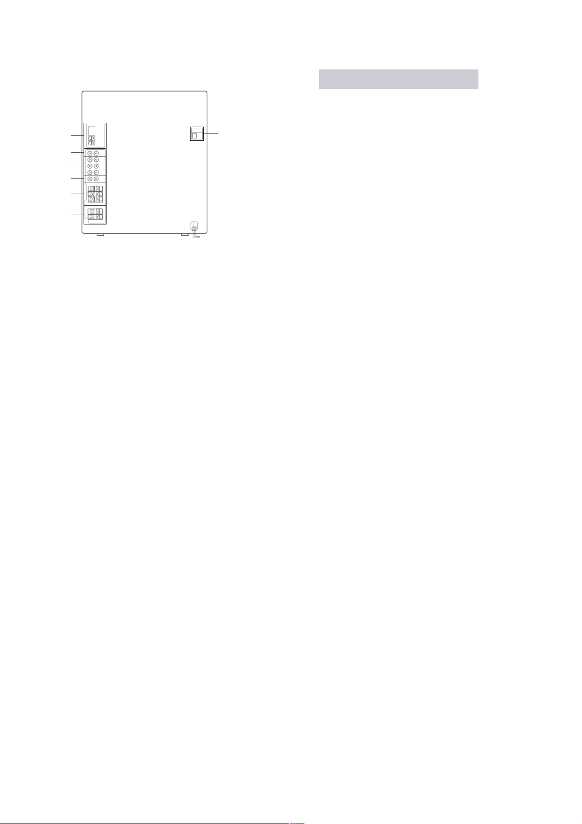
HCD-DX60AV/RG70AV
– Rear Panel –
1
2
3
4
5
6
1 ANTENNA terminal
2 MD (VIDEO) IN jack
3 DVD INPUT
FRONT/REAR/CENTER jack
4 WOOFER/VIDEO OUT jack
5 REAR/CENTER SPEAKER terminal
6 FRONT SPEAKER terminal
7 CD DIGITAL OUT terminal
7
Setting the time
1
Turn on the system.
2
Press CLOCK/TIMER SET on the
remote.
Proceed to step 5 when “CLOCK” appears
in the display.
3
Press v or V repeatedly to select “SET
CLOCK”.
4
Press ENTER.
5
Press v or V repeatedly to set the hour.
6
Press B.
The minute indication flashes.
7
Press v or V repeatedly to set the
minute.
8
Press ENTER.
Tip
If you made a mistake or want to change the time,
start over from step 1.
Note
The clock settings are canceled when you disconnect
the power cord or if a power failure occurs.
6
HCD-DX60AV/RG70AV
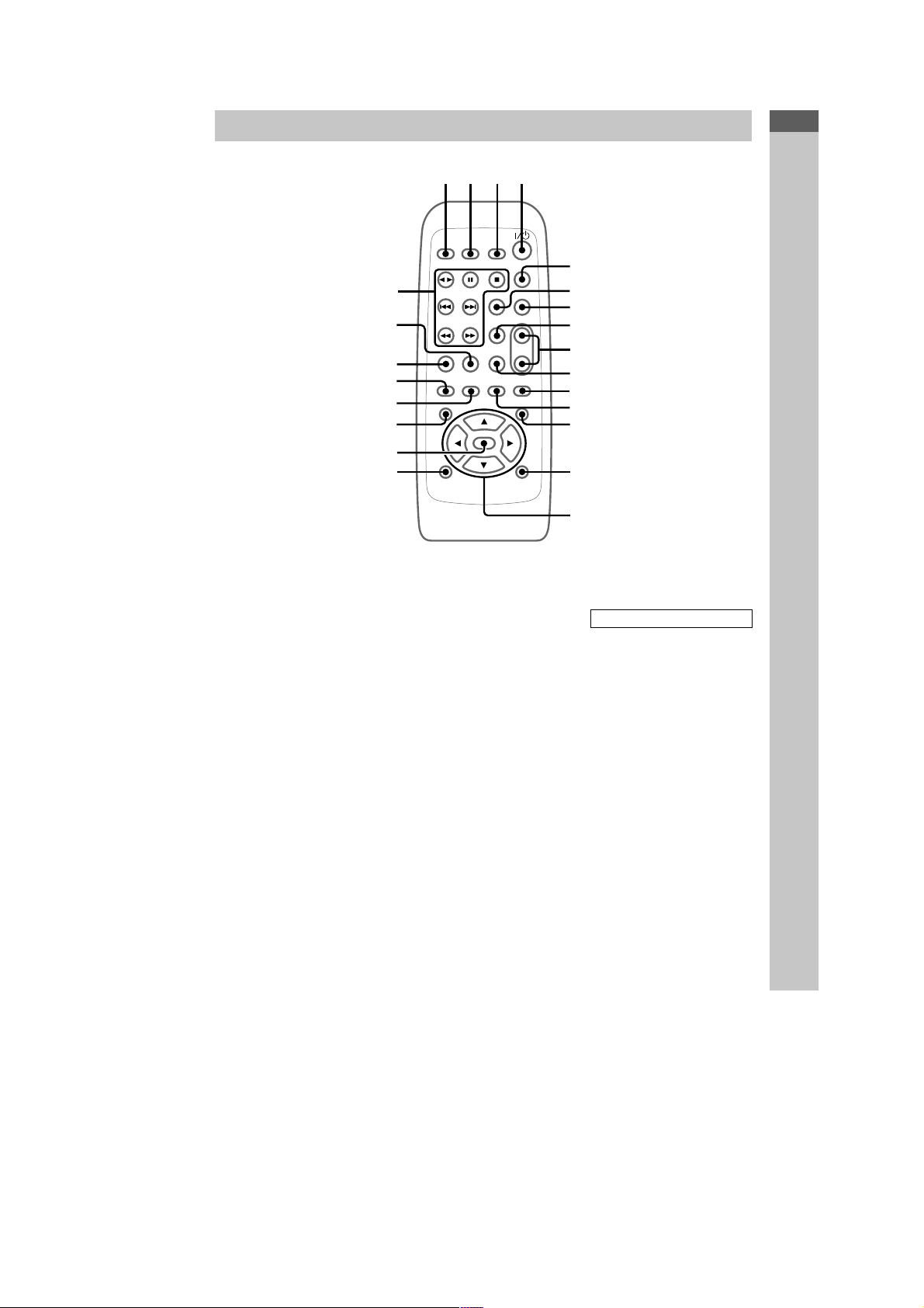
Remote Control
wd
ws
wa
w;
ql
qk
qj
qh
Parts Identification
1234
5
6
7
8
9
0
qa
qs
qd
qf
qg
CD w; (10 — 12, 17, 18)
CLEAR 7 (12)
CLOCK/TIMER SELECT 2
(19, 23)
CLOCK/TIMER SET 3 (9, 18,
23)
D.SKIP 5 (11)
DSP 0 (21)
DVD 5.1CH ws (24, 25)
EFFECT ON/OFF qf (20)
ENTER qj (9, 10, 12 — 15, 18, 19
21, 23, 29)
GAME wa (25)
MD (VIDEO) qa (24)
P FILE qh (21)
PRESET EQ qk (19)
PRESET + wd (14)
PRESET — wd (14)
PROLOGIC ON/OFF 8 (20)
REAR/CENTER LEVEL 6 (8)
SLEEP 1 (22)
TAPE A/B qs (16, 17)
TEST TONE qd (8, 9)
TUNER/BAND ql (13, 14, 17)
TUNING + wd (13)
TUNING — wd (13)
VOL +/— 9
BUTTON DESCRIPTIONS
?/1 (power) 4
v/V/b/B qg
M (fast forward) wd
. (go back) wd
> (go forward) wd
X (pause) wd
nN (play) wd
m (rewind) wd
x (stop) wd
5
7
HCD-DX60AV/RG70AV
• This set can be disassembled in the order shown below.
2-1. DISASSEMBLY FLOW
SET
2-2. CASE (TOP)
(Page 9)
2-3. CD DOOR
(Page 9)
2-4. CD MECHANISM DECK
(CDM58B-K6BD38)
(Page 10)
SECTION 2
DISASSEMBLY
2-5. FRONT PANEL SECTION
(Page 10)
2-7. BACK PANEL SECTION
(Page 11)
2-8. MAIN BOARD
(Page 12)
2-6. TAPE MECHANISM DECK
(Page 11)
2-9. BASE UNIT (BU-K6BD38)
(Page 12)
2-10. DRIVER BOARD,
MOTOR BOARD,
ADDRESS SENSOR BOARD
(Page 13)
8
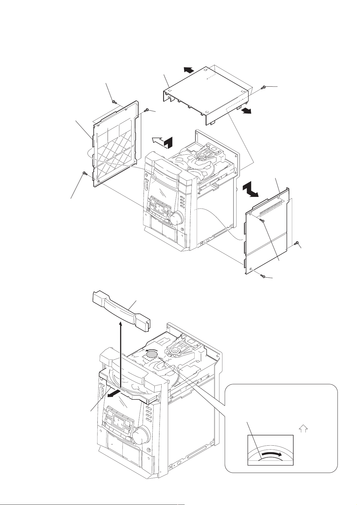
)
Note: Follow the disassembly procedure in the numerical order given.
2-2. CASE (TOP)
qa
case (top)
two screws (case 3 TP2)
5
7
8
case (
side L)
two screws
(+BVTP 3
q;
×
10)
HCD-DX60AV/RG70AV
9
four screws
q;
4
case (
(+BVTP 3
side R)
×
10)
6
screw (case 3TP2)
2-3. CD DOOR
3
CD door
3
two
(+BVTP 3
1
two screws (case 3 TP2
2
screw (case 3 TP2)
screws
×
10)
2
Pull-out the disc tray.
–BOTTOM VIEW–
CD mechanism deck (CDM58B-K6BD38)
1
Turn the pulley in the direction of the arrow.
Front panel side
9
HCD-DX60AV/RG70AV
)
)
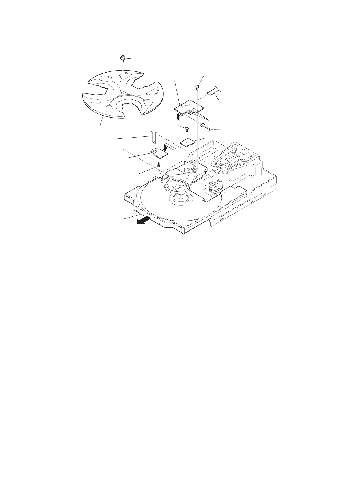
2-4. CD MECHANISM DECK (CDM58B-K6BD38)
5
CD mechanism deck (CDM58B-K6BD38)
2
connector
CN701)
(
4
screw (+BVTP 3
×
10)
1
wire (flat type)
(19 core)
(CN407)
2-5. FRONT PANEL SECTION
6
connector (
1
5
cover (duct)
CN302)
wire (flat type)
(17 core)
8
(+BVTP 3
(CN406)
screw
qa
2
×
10)
connector
(
CN1)
3
screw
(+BVTP 3
4
×
two
screws
(+BVTP 3
10
× 10
)
10
two screws
0
(+BVTP 3
× 10
3
connector
CN2)
(
qs
front panel section
)
9
screw
(+BVTP 3
×
10)
7
screw (+BVTP 3
× 10
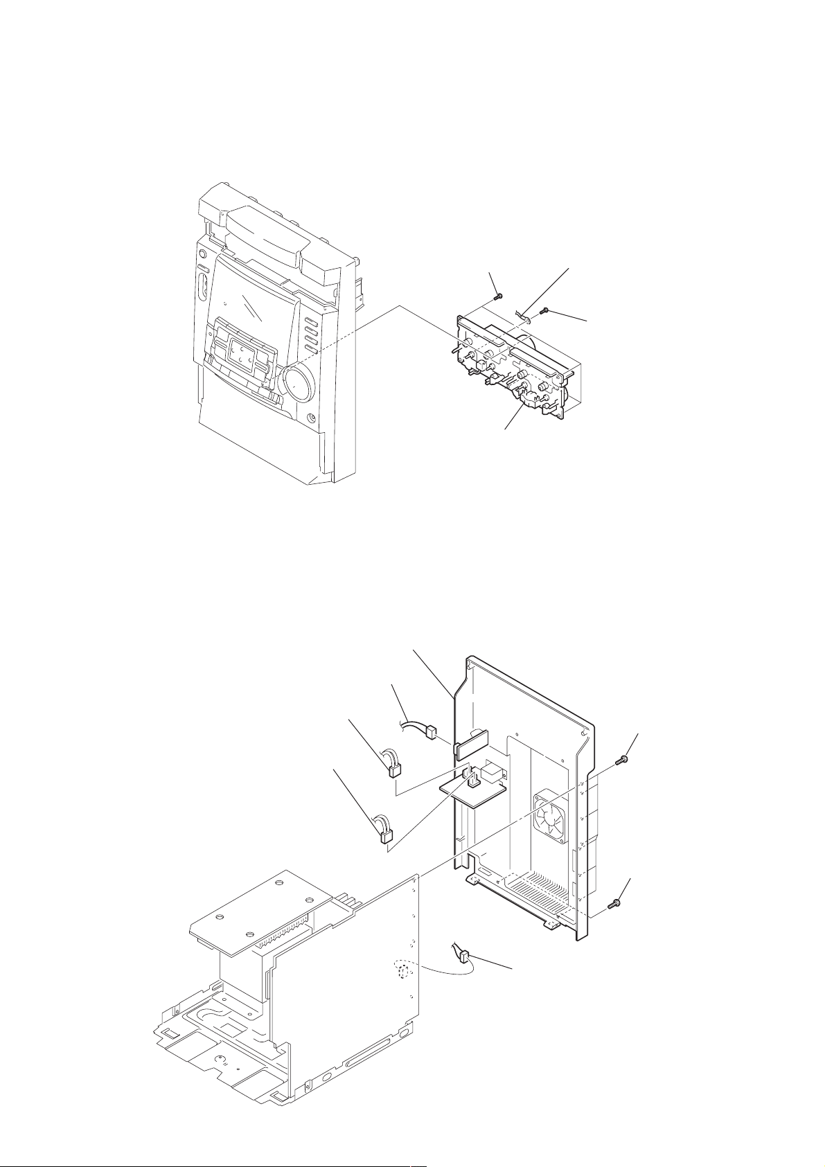
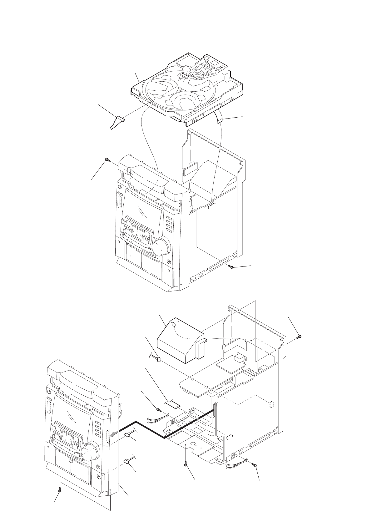
2-6. TAPE MECHANISM DECK
1
five
screws
(+BVTP 2.6
×
HCD-DX60AV/RG70AV
2
8)
harness
1
screw
(+BVTP 2.6
×
8)
2-7. BACK PANEL SECTION
1
1
connector (CN901)
1
connector (CN2)
5
back panel section
connector (CN506)
3
Tape mechanism deck
3
seven screws
(+BVTP 3
×
10)
2
connector
(CN408)
4
two screws
(+BVTP 3
×
10)
11
HCD-DX60AV/RG70AV
)
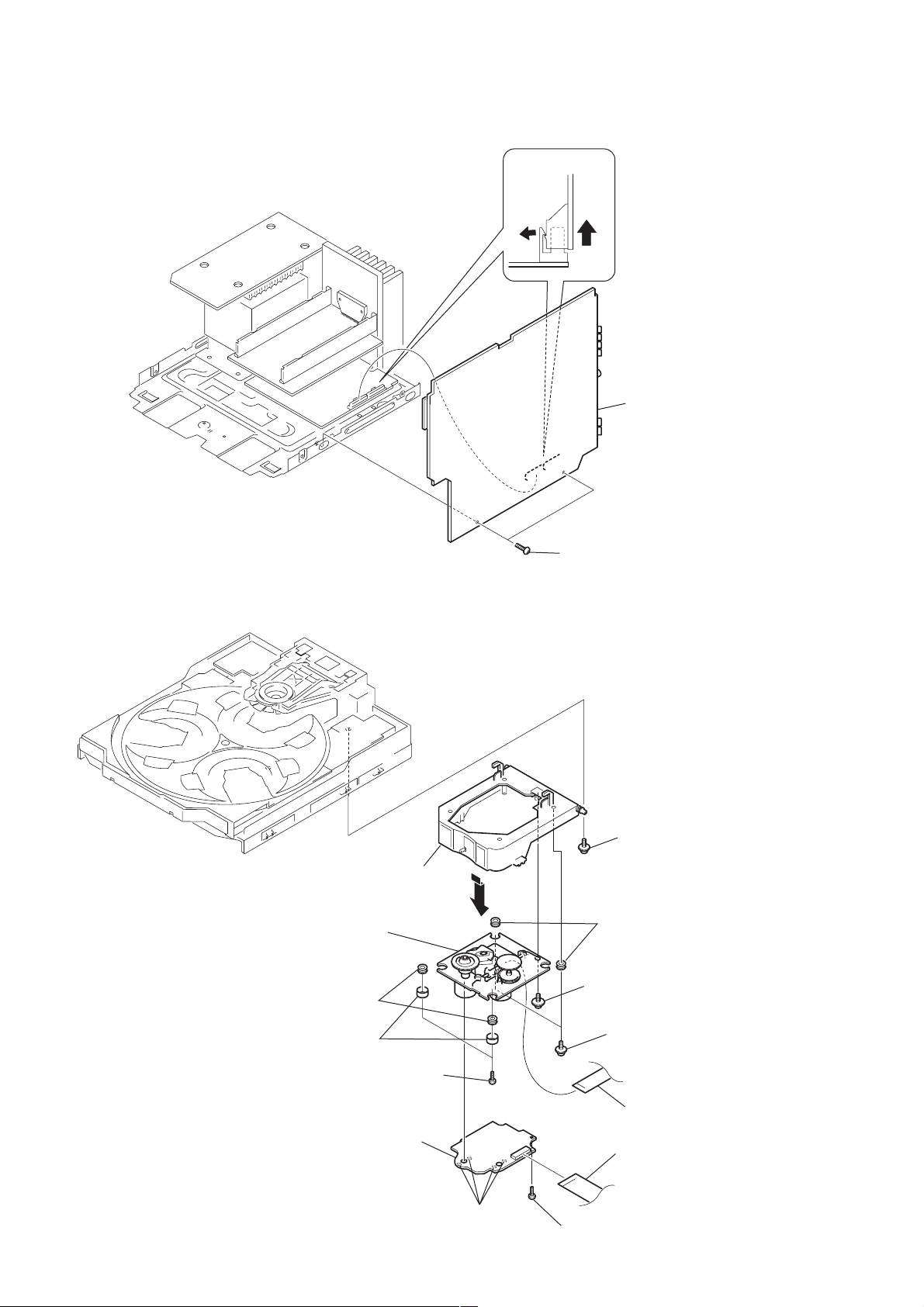
2-8. MAIN BOARD
MAIN board
2
MAIN board
2-9. BASE UNIT (BU-K6BD38)
qf
base unit (BU-K6BD38)
qd
two insulators
3
holder BU assy
qs
1
two screws (+BVTP 3
2
screw (+PTPWH M2.6)
qd
two insulators
qa
screws (DIA. 12)
×
10)
12
9
two stoppers (BU)
8
two screws (M2.6)
7
BD board
6
Remove four solders.
5
screw (M2.6)
0
two
screws (+PTPWH M2.6
4
wire (flat type)
(16 core)
1
wire (flat type)
(19 core)
(CN101)
2-10. DRIVER BOARD, MOTOR BOARD, ADDRESS SENSOR BOARD
qs
qd
3
wire (flat type)
(8 core)
tray
(CN702)
screw (+PTPWH 2.6
qf
screw (BTTP M2.6)
0
×
8)
6
MOTOR board
7
two screws (BTTP M2.6)
8
wire (flat type)
(8 core)
5
Remove the two solderings of motor.
9
qg
ADDRESS
HCD-DX60AV/RG70AV
(CN721)
connector
SENSOR board
4
driver board
1
s
crew (BTTP M2.6)
qa
Pull-out the table.
2
13

HCD-DX60AV/RG70AV
SECTION 3
TEST MODE
[MC Cold Reset]
• The cold reset clears all data including preset data stored in the
RAM to initial conditions. Execute this mode when returning
the set to the customer.
Procedure:
1. Press three buttons x , ENTER , and I/1 simultaneously.
2. The fluorescent indicator tube displays “COLD RESET” and
the set is reset.
[CD Ship Mode]
• This mode moves the pickup to the position durable to vibra-
tion. Use this mode when returning the set to the customer after
repair.
Procedure:
1. Press I/1 button to turn the set ON.
2. Press CD button and I/1 button simultaneously. (Until
“STANDBY” appears)
3. When you release the buttons, a message “LOCK” is displayed
on the fluorescent indicator tube, and the CD ship mode is set.
[MC Hot Reset]
• This mode resets the set with the preset data kept stored in the
memory. The hot reset mode functions same as if the power
cord is plugged in and out.
Procedure:
1. Press three buttons x , ENTER , and DISPLA Y simultaneously .
2. The fluorescent indicator tube becomes blank instantaneously ,
and the set is reset.
[CD Service Mode]
• This mode can run the CD sled motor freely. Use this mode, for
instance, when cleaning the pickup.
Procedure:
1. Press
2. Select the function “CD”.
3. Press three buttons x , ENTER , and Z OPEN/CLOSE simul-
4. The CD service mode is selected.
5. With the CD in stop status, press and hold the > button to
6. To exit from this mode, perform as follows:
Note: • Always move the pickup to most inside track when exiting from
I/1 button to turn the set ON.
taneously.
move the pickup to outside track, or press and hold
the . button to inside track.
1) Move the pickup to the most inside track.
2) Press three buttons in the same manner as step 2.
this mode. Otherwise, a disc will not be unloaded.
• Do not run the sled motor excessively, otherwise the gear can be
chipped.
[Change-over of AM Tuner Step between 9 kHz and
10 kHz]
• A step of AM channels can be changed ov er between 9 kHz and
10 kHz.
Procedure:
1. Press I/1 button to turn the set ON.
2. Select the function “TUNER”, and press TUNER/BAND
button to select the BAND “AM”.
3. Press I/1 button to turn the set OFF.
4. Press ENTER and I/1 buttons simultaneously, and the display
of fluorescent indicator tube changes to “AM 9 k STEP” or
“AM 10 k STEP”, and thus the channel step is changed over.
[GC Test Mode]
• This mode is used to check the software version, fluorescent
indicator tube, LED, keyboard, headphone and volume.
Procedure:
1. Press three buttons x , ENTER , and DISC 2 simultaneously.
2. LEDs and fluorescent indicator tube are all turned on.
3. When ENTER and DISC 2 buttons are pressed simultaneously,
the key number check mode is activa ted . Key numbers of each
key series are displayed and the key check mode is activated.
4. In the key check mode, the fluorescent indicator tube displays
“KEY 000”.
5. When ENTER and DISC 2 buttons are pressed simultaneously,
the key count mode is activated. In this mode, the fluorescent
indicator tube displays “KEYCNT 00”. When each button is
pressed, the key series number increases first, then key value
increases next. However, once a button is pressed, key value is
no longer counted up with the same button.
6. When ENTER and DISC 2 buttons are pressed simultaneously,
the headphone check mode is activated. “H_P ON” is displayed
when headphones are connected, and “H_P OFF” is displayed
when no headphones are connected.
7. When
8. T o exit this mode, press three b uttons mentioned at step 1 in the
ENTER and DISC 2 buttons are pressed simultaneously ,
the volume check mode is activated and “VOLUME FLAT” is
displayed on the fluorescent indicator tube. When you rotate
the volume knob in + direction, “VOLUME UP” is displayed,
and when you rote it in – direction, “VOLUME DOWN” is
displayed.
same manner, or press ENTER and DISC 2 buttons
simultaneously at step 8.
14

HCD-DX60AV/RG70AV
[MC Test Mode]
• This mode is used to check operations of the respective sections
of Amplifier, Tuner, CD and Tape.
Procedure:
1. Press the I/1 button to turn on the set.
2. Press the three buttons of x , ENTER and DISC 3
simultaneously.
3. A message “TEST MODE” appears on the fluorescent indicator
tube. In this mode, it is set as a default setting that VA CS 1 to 5
is displayed when VACS is changed and that number of
repeating times for a tape and a CD is set as endless.
4. When f (CURSOR UP) button is pressed, GEQ increases to
its maximum and a message “GEQ MAX” appears.
5. When F (CURSOR DOWN) button is pressed, GEQ decreases
to its minimum and a message “GEQ MIN” appears.
6. When g (CURSOR LEFT) or G (CURSOR RIGHT) button is
pressed, GEQ is set to flat and a message “GEQ FLA T” appears.
7. In the test mode, the default-preset channel is called even when
the TUNER is selected and an attempt is made to call the preset
channel that has been stored in memory, by oper ating the Shuttle
knob. (It means that the memory is cleared.)
8. When a tape is inserted in Deck B and Tape B function is
activated, and when REC PAUSE/START button is pressed
twice, recording is started. In this case, VIDEO function is
selected automatically as the input source.
9. Select the desired loop by pressing the PLAY MODE button in
the condition that T ape B function is selected as the input source.
Insert a test tape AMS-110A or AMS-RO to Deck A.
10. Press the SPECTRUM button to enter the AMS test mode.
11. After a tape is rewound first, the FF AMS is checked, and the
mechanism is shut off after detecting the AMS signal twice.
12. Then the REW AMS is checked and the mechanism is shut off
after detecting the AMS signal twice.
13. When the check is complete, a message of either OK or NG
appears.
14. With pressing
you can select that VACS is functioned (“VACS ON” is
displayed) or not (“VACS OFF” is displayed) under any
function.
15. When you want to exit this mode, press the I/1 button twice.
The cold reset is enforced at the same time.
SPECTRUM and DISC 1 buttons simultaneously ,
[Indicating Version of the Micro Processor]
When power is off and the set is not in po wer save mode, (the status
that a demo or a clock is displayed)
Procedure:
1. Press x , ENTER and F (CURSOR DOWN) buttons
simultaneously. Version of MC and GC microprocessor are
displayed, for example, “M1.00 G1.00”.
2. Press x , ENTER and f (CURSOR UP) buttons
simultaneously. Model and destination are displayed, for
example, “BG1AV NA G5”.
15
HCD-DX60AV/RG70AV
[Aging Mode]
This mode can be used for operation check of CD section and tape deck section.
• If an error occurred:
The aging operation stops and display status.
• If no error occurs:
The aging operation continues repeatedly.
1. Operating method of Aging Mode
Turn on the main power and select “CD” of the function.
1) Set a disc in DISC1 tray. Select ALL DISC CONTINUE, and REPEAT OFF.
2) Load the tapes recording use into the decks A and B respectively.
3) Press three buttons x , ENTER , and
DISC SKIP/EX-CHANGE simultaneously.
4) Aging operations of CD and tape are started at the same time.
5) To exit the aging mode, perform [MC Cold Reset].
3. Aging Mode in CD section
1) Display state
• No error occurs
Display
AGING[*][*][*][*]
Note:
[*][*][*][*]
Error display
E ** s ## $$ %%
12 34 5
1 **
2 s
3 ##
4 $$
5 %%
: Number of aging operations
The error No. 00 indicates the newest error. As the error No. increases, it means the older error.
When you want to retrieve the error history, press the PLAY MODE button in the case of mechanism error.
Or press the REPEAT button in the case of NO DISC error.
M: Mechanism error
Don’t care
High order digits only
D: Stopped during closing due to problems other than mechanism.
E: Stopped during opening due to problems other than mechanism.
C: Stopped during chucking due to problems other than mechanism.
F: Stopped during EX-opening due to problems other than mechanism.
Emergency related errors (High order digits only)
1: Stopped during chuck-up
2: Stopped during chuck-down
3: Time out by EX-OPEN
5: Time out by EX-CLOSE
D: No disc error
01: FOCUS ERROR
02: GFS ERROR
03: SETUP ERROR
01: NO DISC judgment without chucking retry
02: NO DISC judgment after chucking retry
Status at the time of NO DISC judgment
(High order digits only)
1: STOP
2: SETUP
3: TOC READ
4: ACCESS
5: PLAY BACK
6: PAUSE
7: MANUAL SEARCH (PLAY)
8: MANUAL SEARCH (PAUSE)
• When the buttons
error can be checked.
Display: EMC**EDC** **: Number of times of error (Maximum three times)
• When aging operation is complete, be sure to perform the MC Cold Reset to reset the error history.
x , ENTER and DISC 1 are pressed simultaneously, number of time of the mechanism error and the NO DISC
EMC: Mechanism error
EDC: NO DISC error
16
2) Operation during aging mode
In the aging mode, the program is executed in the following
sequence.
(1) The disc tray opens and closes.
(2) The mechanism accesses DISC 2 and makes an attempt to
read TOC. However, since there are no discs, a message
“CD2 NO DISC” appears.
(3) The mechanism accesses DISC 3 and a message “CD3 NO
DISC” appears.
(4) The disc tray turns to select a disc1.
(5) A disc is chucked.
(6) TOC of disc is read.
(7) The pickup accesses to the track 1, and playing 2 seconds.
(8) The pickup accesses to the last track, and playing 2 seconds.
(9) Every time when an aging operation of step 1 to step 8 is
complete, the display “AGING[*][*][*][*]” value increases
as the number of aging operations is counted up.
(10) Returns to step 1.
3. Aging Mode in Tape Deck section
1) Display state
• No error occurs
Display action now
• Error occurred
Display action last time
HCD-DX60AV/RG70AV
NO. Display action Action contents Final timing
1 TAPE A AG-6 Rewind the TAPE A The top of tape
TAPE B AG-1 Rewind the TAPE B
2 TAPE A AG-2 FWD play the TAPE A 2 minutes playing
3 T APE A AG-3 F.F . the TAPE A 20 second FF or the end
4 TAPE A AG-4 REV play the TAPE A 2 minutes playing
5 TAPE A AG-5 Rewind the TAPE A The top of tape
6 TAPE B AG-2 FWD play the TAPE B 2 minutes playing
7 T APE B AG-3 F.F. the TAPE B 20 second FF or the end
8 TAPE B AG-4 REV play the TAPE B 2 minutes playing
9 TAPE B AG-5 Rewind the TAPE B The top of tape
of tape
of tape
2) Operation during aging mode
In the aging mode, the program is executed in the following
sequence.
(1) Rewind is executed up to the top of tape A and B.
(2) A tape on FWD side is played for 2 minutes.
(3) FF is executed up to either made for 20 second or the end of
tape.
(4) A tape is rever sed, and the tape on REV side is played for 2
minutes.
Note
* REV side of both Tape A and Tape B are played.
(5) Rewind is executed up to the top of tape.
(6) Returns to step 2, and repeat steps from 2 to 5.
[Function Change Mode]
* elect either VIDEO or MD of the external FUNCTION input.
Procedure:
1. Turn on the power.
2. Press the two buttons MD (VIDEO) and I/1 at the same time.
The main power is turned on and the other function of the
previous function is selected and displayed. “MD” or
“VIDEO”.
17
HCD-DX60AV/RG70AV
e
)
SECTION 4
ELECTRICAL ADJUSTMENTS
DECK SECTION
0 dB=0.775 V
1. Demagnetize the record/playback head with a head
demagnetizer.
2. Do not use a magnetized screwdriver for the adjustments.
3. After the adjustments, apply suitable locking compound to the
parts adjust.
4. The adjustments should be performed with the rated power
supply voltage unless otherwise noted.
5. The adjustments should be performed in the order given in this
service manual. (As a general rule, playback circuit adjustment
should be completed before performing recording circuit
adjustment.)
6. The adjustments should be performed for both L-CH and RCH.
• Test Tape
Tape Signal Used for
P-4-A100 10 kHz, –10 dB Azimuth Adjustment
WS-48B 3 kHz, 0 dB Tape Speed Adjustment
Record/Playback Head Azimuth Adjustment
DECK A DECK B
Note: Perform this adjustments for both decks
Procedure:
1. Mode: Playback
test tape
P-4-A100
(10 kHz, –10 dB)
level meter
32
set
Ω
+
–
PANEL board
PHONES jack (JACK701
2. Turn the adjustment screw and check output peaks. If the peaks
do not match for L-CH and R-CH, turn the adjustment screw
so that outputs match within 1dB of peak.
Output
level
within
1dB
L-CH
peak
R-CH
peak
within
1dB
Screw
position
L-CH
peak
Screw
position
R-CH
peak
3. Mode: Playback
test tape
P-4-A100
(10 kHz, –10 dB)
L-CH
set
R-CH
waveform of oscilloscope
in phase 45°90°135°180
32
32
PANEL board
PHONES jack (JACK701)
good
Ω
Ω
oscilloscop
V
+
–
wrong
H
+
–
°
4. Repeat step 1 to 3 in playback (REV) mode.
5. After the adjustments, apply suitable locking compound to the
parts adjusted.
Adjustment Location: Playback Head (Deck A).
Record/Playback/Erase Head (Deck B).
18
forward
reverse
HCD-DX60AV/RG70AV
r
[MAIN BOARD] (Component side)
SRF101
FE101 or FE102
FM TUNED LEVEL
NULL
T101
IC101
Tape Speed Adjustment DECK B
Note: Start the Tape Speed adjustment as below after setting to the test
mode.
Procedure:
1. Turn the power switch on.
2. Press the x button, ENTER button and DISC 3 button
simultaneously.
(The “TEST MODE” on the fluorescent indicator tube display
while in the test mode.)
To exit from the test mode, press the I/1 button.
Mode: Playback
test tape
WS-48B
(3 kHz, 0 dB)
set
frequency counte
32
Ω
+
–
PANEL board
PHONES jack (JACK701)
1. Insert the WS-48B into the deck A and the blank tape into the
deck B.
2. Press the REC PAUSE/START button on the deck B. Then the
deck B is at recording mode.
3. Set the deck A to playback mode.
4. Adjust SFR401 on the MAIN board so that frequency counter
reads 3,000 ± 15 Hz.
5. Frequency difference between deck A and deck B the beginning
of the tape should be within ±1.5 %.
Adjustment Location:
[MAIN BOARD] (Component side)
TUNER SECTION
FM Tuned Level Adjustment
FM RF SSG
75
Ω
coaxial
set
Carrier frequency : 98 MHz
Modulation : AUDIO 1 kHz, 75 kHz
deviation (100%)
Output level : 28 dB (at 75 W open)
Procedure:
1. Supply a 28 dB 98 MHz signal from the ANTENNA terminal.
2. Tune the set to 98 MHz.
3. Adjust SFR101 to the point (moment) when the TUNED
indicator will change from going off to going on.
Adjustment Location: MAIN board
Null Adjustment
FM RF SSG
75
Ω
coaxial
Carrier frequency : 98 MHz
Modulation : AUDIO 1 kHz, 75 kHz
deviation (100%)
Output level : 60 dB (at 75 W open)
FM ANTENNA terminal
(JK101)
set
FM ANTENNA terminal
(JK101)
Sample Value of Wow and Flutter: 0.3% or less W. RMS
TAPE SPEED
(WS-48B)
CN406
SFR401
Procedure:
1. Supply a 60 dB 98 MHz signal from the ANTENNA terminal.
2. Tune the set to 98 MHz.
3. Measure voltage between pin wa of IC101. Adjust T101 ubtil
the voltage becomes 0 V.
Adjustment Location: MAIN board
Adjustment Location
19
HCD-DX60AV/RG70AV
p
r
CD SECTION
Note :
1. CD Block is basically designed to operate without adjustment.
Therefore, check each item in order given.
2. Use YEDS-18 disc (3-702-101-01) unless otherwise indicated.
3. Use an oscilloscope with more than 10MΩ impedance.
4. Clean the object lens by an applicator with neutral detergent
when the signal level is low than specified value with the
following checks.
S-Curve Check
Oscilloscope
BD board
TP(FEO)
TP(VC)
Procedure :
1. Connect oscilloscope to TP (FEO).
2. Connect between TP (FEI) and TP (VC) by lead wire.
3. Connect between TP (AGCCON) and TP (GND) by lead wire.
4. Turn Power switch on.
5. Load a disc (YEDS-18) and actuate the focus search. (In
consequence of open and close the disc tray, actuate the focus
search)
6. Confirm that the oscilloscope waveform (S-curve) is
symmetrical between A and B. And confirm peak to peak level
within 4 ±1 Vp-p.
S-curve waveform
symmetry
A
within 4 ±1Vp-p
B
7. After check, remove the lead wire connected in step 2 and 3.
Note : • Try to measure several times to make sure than the ratio
of A : B or B : A is more than 10 : 7.
• Take sweep time as long as possible and light up the
brightness to obtain best waveform.
RF Level Check
oscilloscope
BD board
TP(RF)
TP(VC)
Procedure :
1. Connect oscilloscope to TP (RF).
2. Connect between TP (AGCCON) and TP (GND) by lead wire.
3. Turned Power switch on.
4. Load a disc (YEDS-18) and playback.
5. Confirm that oscilloscope waveform is clear and check RF signal
level is correct or not.
6. After check, remove the lead wire connected in step 2.
Note: Clear RF signal waveform means that the shape “◊” can be
clearly distinguished at the center of the waveform.
RF signal waveform
VOLT/DIV : 200mV
TIME/DIV : 500ns
level : 1.45 ± 0.3Vp-
E-F Balance (1 Track jump) Check
oscilloscope
BD board
TP (TEO)
TP (VC)
+
–
Procedure:
1. Connect oscilloscope to TP (TEO) and TP (VC) board.
2. Turned Power switch on.
3. Load a disc (YEDS-18) and playback the number five track.
4. Press the gG button. (Becomes the 1 track jump mode.)
5. Confirm that the level B and A (DC voltage) on the oscilloscope
waveform.
1 track jump waveform
Center of
waveform
B
0V
±
level=1.3
Specification level: x 100=less than ±22%
0.6Vp-p
A
B
Symmetry
A (DC voltage)
6. After check, remove the lead wire connected in step 1.
RF PLL Free-run Frequency
Procedure :
1. Connect frequency counter to test point (XPCK) with lead wire.
BD board
TP (XPCK)
frequency counte
+
–
2. Turned Power switch on.
3. Put the disc (YEDS-18) in to play the number five track.
Confirm that reading on frequency counter is 4.3218MHz.
20
Adjustment Location:
[BD BOARD] (Conductor Side)
HCD-DX60AV/RG70AV
TP
(TEO)
12
(FEO)
TP
(VC)
TP
(AGCCON)
IC103
TP
(RF)
24
TP
(FEI)
TP
TP
(XPCK)
1
40
41
2021
IC101
61
60
TP
(DGND)
1
80
21

HCD-DX60AV/RG70AV
MEMO
22
SECTION 5
DIAGRAMS
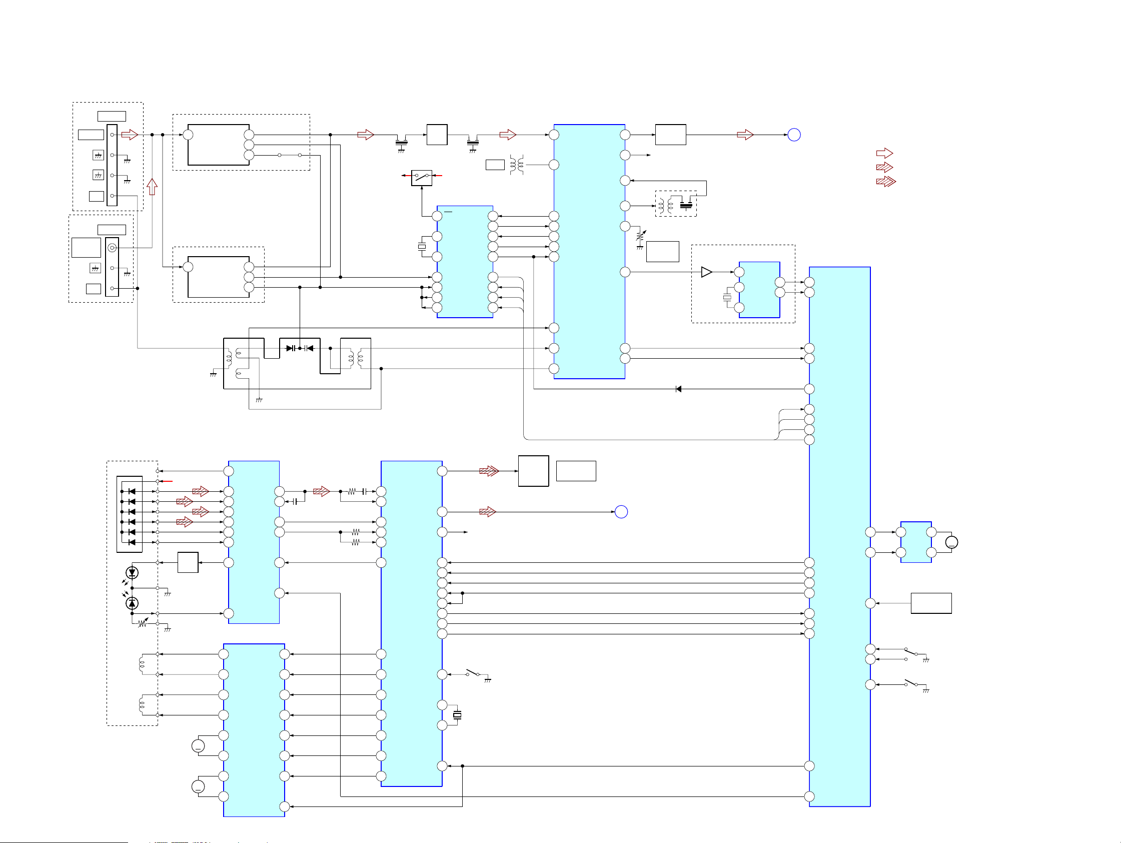
5-1. BLOCK DIAGRAM – TUNER/CD Section –
(DX60AV/RG70AV: US)
FM 75Ω
AM
FM 75Ω
COAXIAL
AM
(RG70AV: AEP)
JK101
ANTENNA
JK101
ANTENNA
(DX60AV/RG70AV: US)
FE101
1
(RG70AV: AEP)
1
ANT IN
ANT IN
IF OUT
OSC OUT
FE102
7
8
VT
5
7IF OUT
8OSC OUT
5VT
JR102
X101
Q102
Q101
RF IF
AMP
10
24
15
18
17
19
1
FM/AM
IC102
FM
XIN
XOUT
FM OSC
VT1 IN
VT1
PD1
PLL
FM/AM IF
AM OSC
CF101 CF102
+B +12V
4.5MHz
HCD-DX60AV/RG70AV
AM/FM IF AMP, MPX
IC101
1
FM IF
T101
NULL
12
FM
7
14
2VCO STOP
8IF REQ
DO
6DO
DI
DI
4DI
CL
CE
CL
5
CE
3
5
FM DET
9
IF OUT
12
AM/IF
24
AM OSC
13
VCO STOP
8
IF REQ MUTE
L OUT
R OUT
AM MIX OUT
FM SD ADJ
FM/AM DET
11
10
18AM IF IN
19
3
16
BUFFER
Q103
R-CH
IFT101
SRF101
FM TUNED
LEVEL
Q105
X102
4.332MHz
(RG70AV: AEP)
RDS DECODER
IC103
4
MUX
DATA
14
XO
13
XI
L-CH
INT
(Page 24)
2
16
A
SYSTEM CONTROLLER
IC401 (1/4)
21
RDS DATA
20
RDS INT
• R-CH : R-ch is omitted due to same as L-ch.
• Signal Path
: FM
: CD
: DIGITAL OUT
OPTICAL PICK-UP
BLOCK
(KSM-213DCP)
GND
VR
FOCUS
COIL
TRACKING
COIL
20
13
RB101
1
3
VC
+5V
A
B
C
D
E
F
LD
PD
F+
F-
T+
T-
Q101
LESER
DRIVE
SLED
MOTOR
SPINDLE
MOTOR
MM
MM
12
VC
5
A
6
B
7
C
8
D
11
E
10
F
3
LD
4
PD
MOTOR/COIL DRIVE
13
CH1OUTR
14
CH1OUTF
11
CH2OUTR
12
CH2OUTF
18
CH3OUTR
17
CH3OUTF
16
CH4OUTR
15
CH4OUTF
RF AMP
IC103
IC102
4
122
RFO
RFI
FE
TE
CH1RIN
CH1FIN
CH2RIN
CH2FIN
CH3RIN
MUTE
14
55
1511
67
16
17
14
13
22LD ON
21HOLD SW
3
2
6
5
23
24CH3FIN
25CH4IN
20
9
DIGITAL SERVO
DIGITAL SIGNAL PROCESSOR
D/A CONVERTER
IC101
DOUT
60
51
RFAC
43
RFDC
LOUT1
LOUT2
SCLK
SCOR
SQSO
SENS
SSTP
XTAI
XTAO
72
75
5DATA
7CLOK
6XLAT
2SQCK
9
20
1
8
27
66
67
3XRST
39
FE
41
TE
40
SE
14
XLON
32
FFDR
33
FRDR
30
TFDR
31
TRDR
29
SRDR
28
SFDR
26
MDP
R-CH
X101
16.9344MHz
S101
LIMIT
IN SW
PH401
OPTICAL
DIGITAL
OUT
AM RF IN
22
AM OSC
23
V REG
DIGITAL OUT
CD
CD L OUT
TUNED
STEREO
(Page 24)
24
6
7
D108
DO
DI
CL
CE
B
TUNED
23
STEREO
22
ST MUTE
27
ST DIN
26
ST DOUT
28
ST CLK
25
ST CE
35
CD DAT OUT
37
CD CLK
42
XLT (CD)
33
SQ CLK
19
SCOR
32
SQ DAT IN
SENS
34
(CXD2587 SENS)
BU UP/DOWN
43
XRST (CD)
40
HOLD
LOAD IN
T SENS
IC701
44
45LOAD OUT
49
46OPEN
47CLOSE
48
9
MOTOR
DRIVE
7
TBL ADDRESS
4
2
IC711
SENSOR
OPEN/CLOSE
M
S701
S711
UP/DOWN
M721
TURN
MOTOR
2323
 Loading...