

Sony HAW-EIBU Installation Manual

Network Video Recorder
Installation Manual
Before operating the unit, please read this manual and the Safety Regulations
thoroughly and retain them for future reference.
HAW-EIBU
Software Version 2016 R2 and Later
4-684-078-01 (2)
© 2016 Sony Corporation

2
Table of Contents
Usage Precautions ...................................4
Package Contents ....................................6
System Requirements ..............................7
Names and Functions of Parts................ 8
Front (without the Front Panel) .................... 8
Front (with the Front Panel) ......................... 8
Rear ............................................................... 9
Acquiring Reference Manuals and
Technical Documents ............................10
System Configuration............................ 11
Single Network Video Recorder
Systems ....................................................... 11
Multi Network Video Recorder Systems ... 12
Preparation .............................................13
Step 1: Installation .................................13
Installing without a Rack ............................ 14
Step 2: Installing the HDDs ...................14
Step 3: Connections ...............................16
Connecting the Monitors ............................ 16
Connecting the Keyboard and Mouse ........ 16
Connecting the Power Cord ........................ 16
Connecting to a Network ............................ 16
Connecting Other Devices .......................... 17
Step 4: System Settings ........................17
Registering the Software License Code (SLC)
and Acquiring the License File ................... 17
Verifying the Software Version .................. 17
Adding Device Licenses ............................. 18
Installing the Management Server on a
Computer .................................................... 18
Turning On the Unit ...................................18
Initial Setup for Windows .......................... 18
Changing the Keyboard Layout .................. 19
Closing the Pagefile Wizard ....................... 19
Configuring the Login Password ................ 19
Configuring the IP Address ........................ 20
Configuring Monitor Settings ..................... 20
Configuring Initial Settings with Setup
Wizard ........................................................ 21
Configuring the Recording Disk
Settings ....................................................... 22
Updating the Device Pack Version ............ 25
Starting Management Client ...................... 26
Authorizing the Recording Server ............. 26
Configuring the Recording Destinations .... 26
Registering Cameras .................................. 27
Quitting Management Client ...................... 28
Step 5: Verifying Operation ...................29
Step 6: Activation ...................................29
Exporting License Request Files (.lrq) ....... 29
Acquiring Activated Software License Files
(.lic) ............................................................ 30
Importing Activated Software License Files
(.lic) ............................................................ 30
Step 7: Data Backup ..............................31
Third Party Software Terms and
Conditions ..............................................31
Inno Setup License ..................................... 31
Troubleshooting ..................................... 58
Specifications .........................................59

3
Disclaimer of liability for recorded content
Sony Corporation does not accept any liability
whatsoever for any problems arising from a failure to
record, or from damage or erasure of recorded content on
this equipment, for any reason. This includes claims for
compensation of recorded content, and for any
concomitant and consequential damages. Sony
Corporation will not repair, restore, or duplicate any
recorded content. Your use of this product is subject to
these conditions.
• Reproduction or duplication, in whole or part, of the
software or operation manual supplied with the
server, as well as renting or leasing of the software
without the authorization of the right holder is
prohibited under copyright law.
• Sony assumes no responsibility for damages, loss of
income, or any claims from a third party arising out
of use of the server or supplied software.
• For complete terms and conditions of the warranty
for the server, refer to the warranty card included in
the package.
• The software supplied with the server cannot be used
with any other servers.
• It is not possible to install any software into the
equipment other than the software supplied by Sony
specifically for use with the equipment.
• Note that the specifications of the server and
supplied software are subject to change for
improvement without prior notice.

4
Usage Precautions
Important Information About Safety
• Be sure to connect the unit to a power source that
conforms fully to the electrical specifications of this
unit.
• Do not coil the power cord or bundle it with other cords.
Do not piggy back connections. If current ratings are
exceeded, there is a risk of fire and other accidents.
• Make sure that all AC outlets and power cords are
properly grounded.
• Do not use the unit with the panel opened or removed.
Otherwise there is a risk of fire and electric shock. Do
not attempt to open or remove the panel yourself.
Always consult your supplier if opening is necessary.
Important Information About Installation
Locations for use/storage
To prolong the life of the product, avoid use or storage in
the following locations.
• Locations that can become extremely hot or cold. (Be
sure to use the unit that conforms fully to the
specifications of this unit.)
• Locations exposed for an extended time to direct
sunlight, and locations near heating appliances. (Note
that the temperature in a closed car in summer can
exceed +50 ºC/+122 ºF.)
• Locations with high levels of humidity or dust
• Locations subject to strong vibrations
• Locations subject to strong magnetic fields
• Locations in the vicinity of radio or TV transmitters
creating a strong magnetic field
Do not stack units or place the unit on other
objects that generate heat
When one unit is stacked on top of another unit, the heat
generated by both units can get extremely hot. Do not
stack units on top of each other or place the unit on other
objects that may generate heat.
Do not block the ventilation openings
• The ventilation openings on the sides of the unit serve
to prevent internal heat buildup. Always leave a
clearance on both sides as well as behind and above the
unit.
• Do not use the unit in a closed box or other enclosure.
Precautions for rack installations
When installing the unit on a rack, take the following
measures to ensure operation within the specified
operating temperature.
• Place a fan to reduce the ambient temperature of the
rack.
• Maintain a space of 1U rack-mount size (1.75 in.
(approx. 44.5 mm)) or more above and below the unit.
• Do not obstruct the ventilation holes.
• Ventilation holes are located on the bottom of the front
panel, so be sure to attach rubber feet when installing
the unit on a shelf, for example.
Use the unit in a horizontal position
• The unit is designed to be operated in a horizontal
position.
• Do not install the unit on a slanted surface, and protect
the unit from shocks.
• When the unit is dropped or otherwise subject to strong
shocks, it can be seriously damaged.
Maintenance
• Before cleaning the unit or performing any other kind
of maintenance, be sure to disconnect the power cord
from the AC outlet.
• For cleaning, lightly wipe the cabinet and panels with a
dry cloth. To remove stubborn stains, lightly moisten
the cloth with a mild, neutral detergent and wipe with a
dry cloth afterwards.
• Do not use cleaning alcohol, solvents, benzine,
insecticide, or any other volatile substances, because
these may damage the finish and lead to discoloration.
Transport
Use the original packing material or similar packing to
protect the unit from shocks.
Security
SONY WILL NOT BE LIABLE FOR DAMAGES OF
ANY KIND RESULTING FROM A FAILURE TO
IMPLEMENT PROPER SECURITY MEASURES ON
TRANSMISSION DEVICES, UNAVOIDABLE DATA
LEAKS RESULTING FROM TRANSMISSION
SPECIFICATIONS, OR SECURITY PROBLEMS OF
ANY KIND.
Depending on the operating environment, unauthorized
third parties on the network may be able to access the unit.
When connecting the unit to the network, be sure to
confirm that the network is protected securely.
From a safety standpoint, when using the unit connected
with the network, it is strongly recommended to access
the Control window via a Web browser and change the
access limitation settings from the factory preset values.
Changing the password regularly is also recommended.

5
Do not browse any other website in the Web browser
while making settings or after making settings. Since the
login status remains in the Web browser, close the Web
browser when you complete the settings to prevent
unauthorized third parties from using the unit or harmful
programs from running.
• Anti-virus software cannot be installed on the unit, so
be sure to ensure anti-virus protection via firewalls and
routers. In addition, be sure to check for the presence of
viruses before connecting USB devices to the unit.
• Do not connect the unit directly to the Internet. When
Internet connection is absolutely necessary, be sure to
use a firewall.
Condensation
If the unit is suddenly taken from a cold to a warm
location, or if ambient temperature suddenly rises,
moisture may form on the outer surface of the unit and/or
inside of the unit. This is known as condensation. If
condensation occurs, turn off the unit and wait until the
condensation clears before operating the unit. Operating
the unit while condensation is present may damage the
unit.
Consumable parts
The fan is a consumable part that will need periodic
replacement.
When operating at room temperature, a normal
replacement cycle will be about 5 years.
However, this replacement cycle represents only a
general guideline and does not imply that the life
expectancy of this part is guaranteed. For details on parts
replacement, contact your dealer.
Precautions for HDDs
The unit is not supplied with hard disk drives (HDDs) but
will not operate without one installed.
HDDs are precision devices. If subject to shock,
vibration, static electricity, high temperature or humidity,
data loss can occur. When installing HDDs or operating
the unit with HDDs installed, observe the following
precautions.
Protect from shocks and vibrations
When subject to shocks or vibrations, the HDD can be
damaged and loss of data on the HDD can occur.
• When transporting the unit, use the specified packing
material. When transporting on a dolly or similar, use a
type which does not transmit excessive vibrations.
Excessive shocks and vibrations can damage the HDD.
• Never move the unit while it is powered.
• Do not remove panels or outer parts of the unit.
• When placing the unit on a floor or other surface, make
sure that the unit is equipped with the specified rubber
feet, and put the unit down carefully. If there are no feet,
mount the rubber feet first.
• Do not place the unit near other devices that may
become a source of vibrations.
Wait for 30 seconds after turning power off
For a brief interval after the power is turned off, the
platters inside the HDD will still keep spinning and the
heads will be in an insecure position. During this interval,
the unit is more susceptible to shocks and vibrations than
during normal operation. For a period of at least 30
seconds after turning power off, avoid subjecting the unit
even to very light shocks. After this period, the hard disk
will be fully stopped and the unit can be manipulated.
Temperature and humidity related precautions
Use and store the unit only in locations where the
specified temperature and humidity ranges are not
exceeded. (Be sure to use the unit that conforms fully to
the specifications of this unit.)
In general, the performance of HDDs tends to diminish
when operating in higher ambient temperatures, and this
in turn shortens their replacement cycles.
Although normal operation is possible within the
specified operating temperature, we recommend
operation in an ambient temperature of +25 °C (+77 °F)
to improve the HDD’s replacement cycle.
When the HDD seems to be faulty
Even if the HDD is showing signs of malfunction, be sure
to observe all the above precautions. This will prevent
further damage from occurring until the problem can be
diagnosed and corrected.
Replacement of the HDD and other consumable
parts
The HDD and battery are consumable parts that will need
periodic replacement. When operating at room
temperature, a normal replacement cycle will be about
two to three years. However, this replacement cycle
represents only a general guideline and does not imply
that the life expectancy of these parts is guaranteed. For
details on parts replacement, contact your dealer.
Precautions for using USB devices
• This unit supports USB 2.0, USB 3.0, Mass Storage
class devices. However, it does not support USB 2.0,
USB 3.0, Mass Storage class HDDs or CD/DVD drives.
Do not connect mass storage class devices other than
USB flash memory devices to the unit. Be aware that
errors may still occur when writing data to a USB 2.0,
USB 3.0, Mass Storage class memory device,
depending on the type of device used. If errors occur
when writing data, use a USB memory device of a
different type.
• To ensure proper operation of USB devices, do not
connect the devices via a USB hub. Connect the devices

6
directly to the USB connectors on the unit. Operation is
not guaranteed when devices are connected via a USB
hub, USB switch, or extension cable.
Protect data from power interruptions
If the power supply is interrupted while the unit is in
operation, data may be damaged. Be sure to take
measures against power outages to protect data.
Package Contents
Check that the following items are included in this
package:
• HAW-EIBU (1)
• Front panel (1)
• Before Using this Unit (leaflet) (1)
• Front panel keys (2)
• Installation Manual (this document) (1)
• WEEE booklet (1)
• Safety Regulations (leaflet) (1)
• Warranty booklet (1)
• Rubber feet (4)
• HDD screws (40)
• This package may contain additional hardware and/or
documentation for those options.
• Save the boxes and packing materials for future use.
Notes

7
System Requirements
The hardware required in order to use this unit are as
follows.
• Hard disk drives (HDDs)
1)
•Monitor
2)
• Sony network cameras
3)
• USB keyboard
4)
• USB mouse
5)
•Network hub
• 1000Base-T/100Base-TX/10Base-T cable
• USB flash memory device
6)
1) Contact your dealer for details about compatible HDDs.
2) HDMI-compatible devices, DisplayPort-compatible
devices, and computer displays that accept RGB input are
supported.
A resolution of at least 1024 × 768 and 16-bit color are the
minimum suggested specifications.
3) Contact your dealer for details about compatible Sony
network cameras.
4) Use a USB keyboard with a cable. However, keys other than
the standard may not function. Wireless or infrared USB
keyboards may also not function properly.
5) Use a USB mouse with a cable. Wireless or infrared USB
mice may not function properly. Functions such as threebutton and wheel operations may also function improperly.
6) Required when backing up system information such as logs.
– This unit supports USB 2.0, USB 3.0, and Mass Storage
class devices. However, it does not support USB 2.0, USB
3.0, and Mass Storage class USB HDDs or CD/DVD
drives. Do not connect mass storage class devices other
than USB flash memory devices to the unit. Be aware that
errors may still occur when writing data to a USB 2.0,
USB 3.0, and Mass Storage class memory device,
depending on the type of device used. If errors occur when
writing data, use a USB flash memory device of a different
type.
8
Names and Functions of Parts
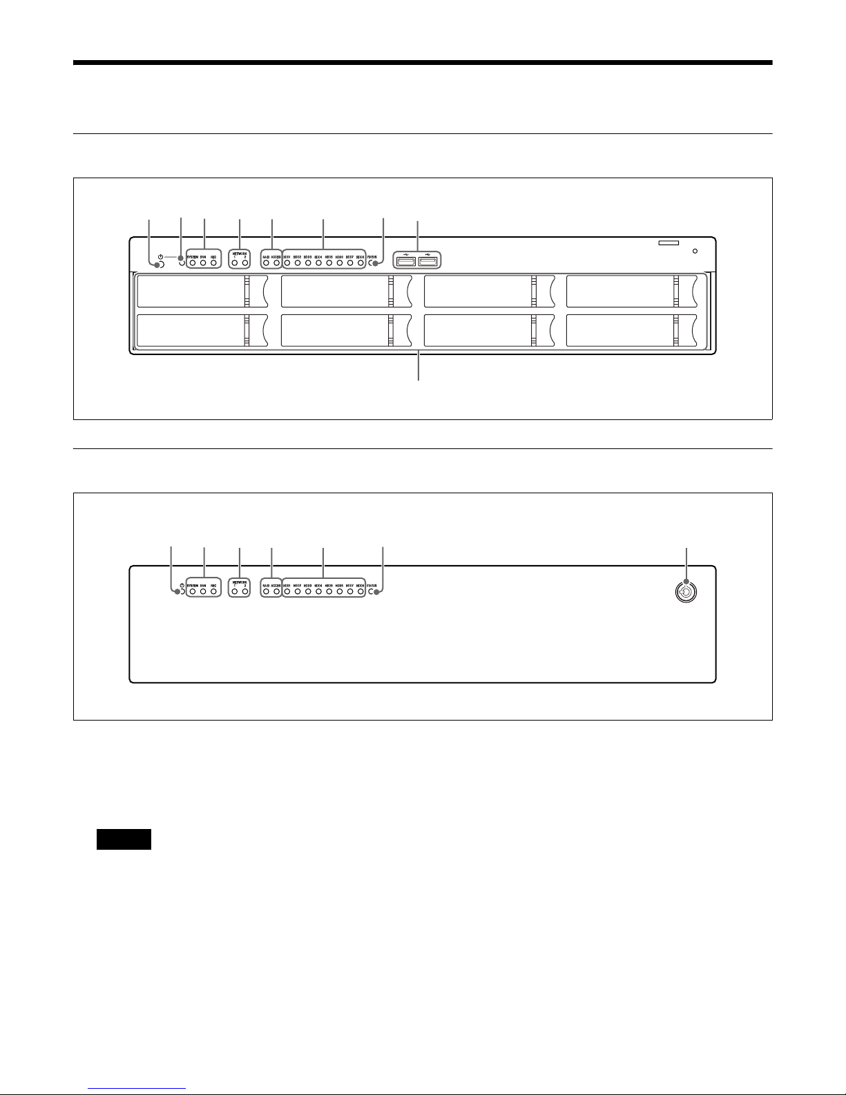
Front (without the Front Panel)
Front (with the Front Panel)
a 1 Power switch
Press this to turn on the unit.
Pressing the power switch again during this time
turns off the unit.
Pressing and holding down the power switch
(approximately 4 seconds) turns off the unit
forcefully.
b 1 POWER LED
Lights blue when the unit is turned on.
c SYSTEM LED
During operation, this LED is lit green when the
system is functioning normally. When a system error
or other problem occurs, it lights or blinks red.
If this LED lights or blinks red, contact your Sony
dealer.
FAN LED
Lights green when the internal fan is functioning
properly. Lights red or amber when a fan failure
occurs.
REC LED (intended for future expansion)
Does not function currently.
adcbe
g
f
h
i
j
dcbe
g
f
Caution
9
d NETWORK LEDs (1 and 2)
Light blue when there is a link to the network.
Blink blue when the network is being accessed.
e RAID LED
Lights green when the RAID configuration is
functioning properly.
Lights red if a fatal problem exists with the RAID due
to an internal HDD failure, for example.
Lights amber if the RAID is degraded or rebuilding.
ACCESS LED
Blinks blue when the HDDs are accessed.
f HDD LEDs (1 to 8)
Light green when the internal HDDs are functioning
properly.
Light red when failures or other problem occurs.
Also, light amber during the rebuilding of RAID.
These remain unlit when HDDs are not recognized.
g STATUS LED
Indicates the operation status when using a USB flash
memory device to acquire logs.
Lights green when a USB flash memory device
formatted to acquire logs is recognized.
Blinks green when log acquisition starts
automatically and is in progress.
Lights green again when log acquisition is successful.
Lights red if log acquisition fails.
Do not remove the USB flash memory device while
the LED is blinking.
h USB 3.0 connectors (1 and 2)
Use this connector to connect a USB mouse,
keyboard, or USB flash memory to the unit.
i HDDs
For details on maintenance, contact your Sony dealer.
j Lock
Use this in conjunction with the supplied front panel
key to lock the front panel.
When the front panel is locked, you cannot remove it.
When attaching the front panel, make sure the lock is
the unlocked state before you attach the front panel.
You can distinguish the locked position from the
unlocked position by looking at the lock, as illustrated
below.
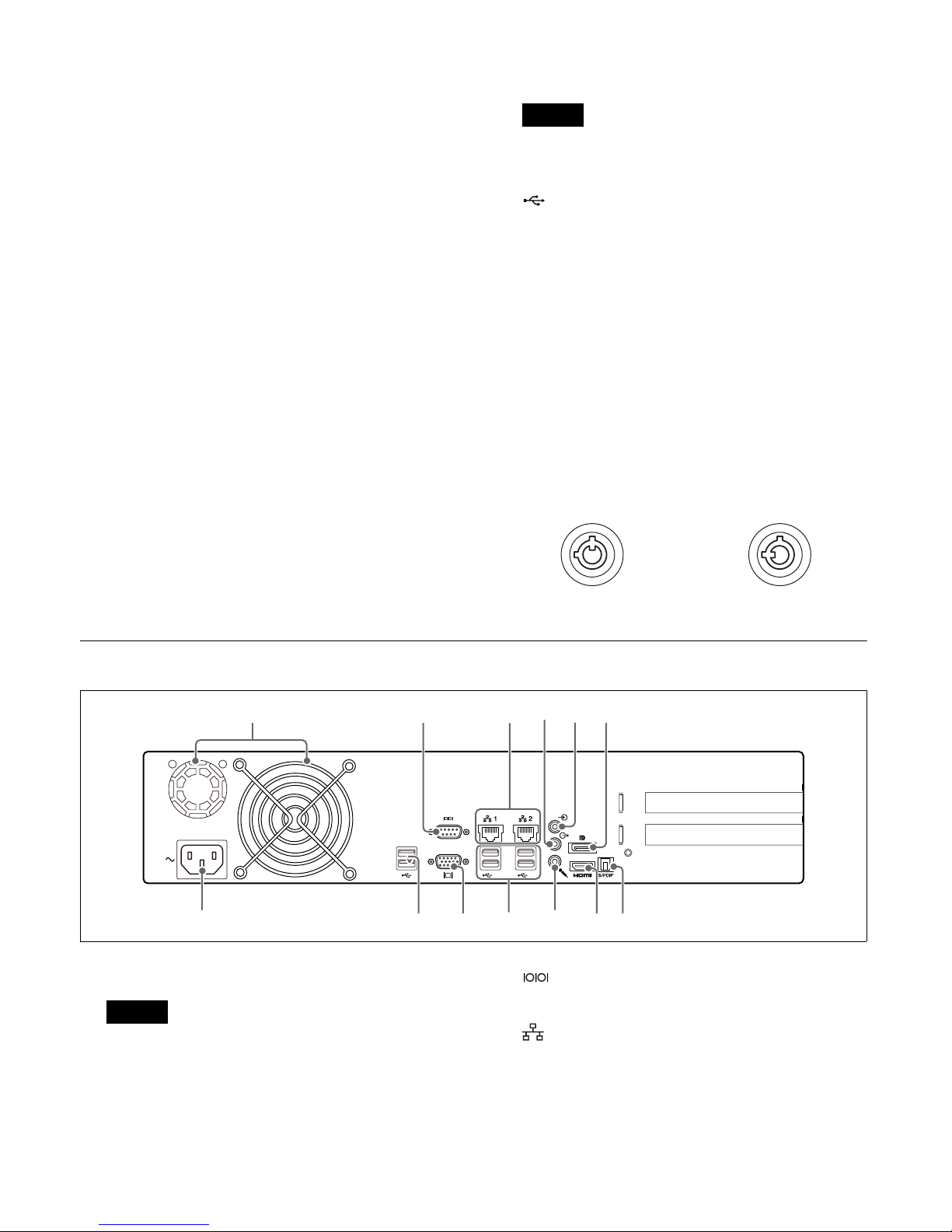
Rear
a Fans
Take care not to obstruct the fan grille. If the grille is
obstructed, heat may build up in the unit, leading to
damage and/or fire.
b RS-232C connector (used for future
expansion)
c LAN connectors (1 and 2)
Use these connectors to connect 10 Base-T,
100 Base- TX, or 1000 Base-T network cables.
LAN1: Network cameras
LAN2: Network cameras (LAN2 can only be used
when using a different segment from LAN1.)
Caution
The front panel is locked The front panel is unlocked
adcbe
ilkj hg
f
m
Caution
10
• Do not configure LAN connectors 1 and 2 to the
same network segment.
• For details on using iSCSI storage, contact your
Sony dealer.
• For safety, do not connect the connector for
peripheral device wiring that might have excessive
voltage to the following ports.
– LAN1 connector
– LAN2 connector
Follow the instructions for the above ports.
• When you connect the LAN cable of the unit to
peripheral device, use a shielded-type cable to
prevent malfunction due to radiation noise.
d AUDIO OUT (line output) connector (stereo)
Use this connector to output audio to a peripheral
audio device.
e AUDIO IN (line input) connector (stereo)
Use this connector to input audio from a peripheral
audio device.
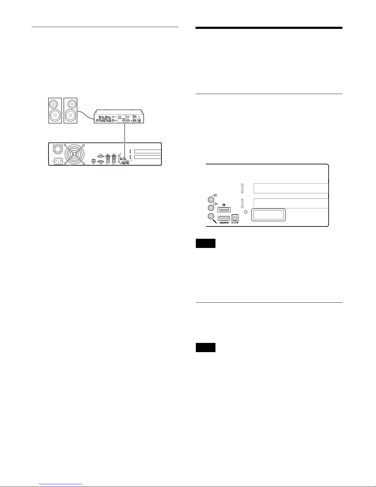
f DisplayPort connector
Use this connector to connect a monitor that supports
DisplayPort input.
g S/PDIF connector
Use this connector to connect a device that supports
S/PDIF input.
h HDMI monitor connector
Use this connector to connect a monitor that supports
HDMI input.
i AUDIO IN (microphone input) connector
Use this connector to input audio from a peripheral
audio device, such as a microphone.
Plug-In Power microphones are supported.
j USB 3.0 connectors (1 to 4)
Use these connectors to connect a USB mouse,
keyboard, or USB flash memory to the unit.
k Monitor connector
Use this connector to connect a monitor that supports
analog RGB input.
l USB 2.0 connectors (1 and 2)
Use these connectors to connect a USB mouse,
keyboard, or USB flash memory to the unit.
m Power supply connector
Use this connector to connect the power cord.
Acquiring Reference
Manuals and Technical
Documents
Reference manuals and technical documents for the unit
are available online.
Access the following websites via the URLs, and
download the necessary manuals and documents.
• NVMS Enterprise Edition Administrator Manual
• NVMS License Guide
https://www.sony.net/CameraSystem/NVMS/Manuals
• NVMS Enterprise Edition Maintenance Guide
• NVMS Enterprise Edition System Design
Requirements
https://www.sony.net/CameraSystem/NVMS/TechnicalDocuments
Caution
CAUTION
11
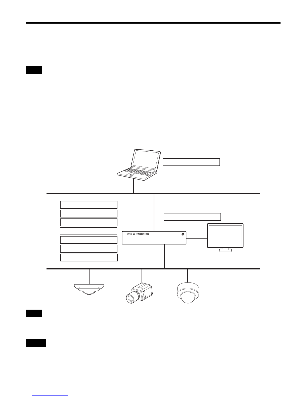
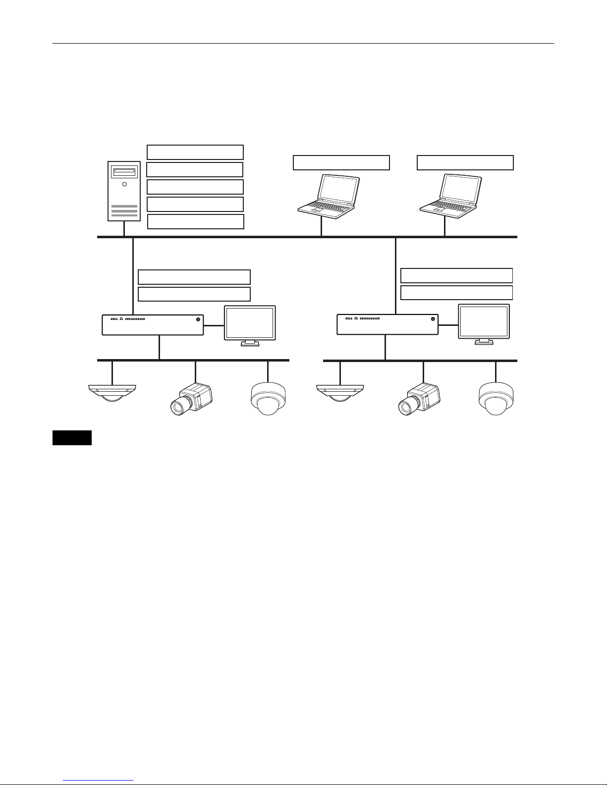
System Configuration
The location at which the management server should be installed differs depending on the number of Network Video
Recorder units that exist in the system. The recording server should always be installed on the unit.
The management server is the core component of the Network Video Management System Enterprise Edition. This server
processes and distributes the system configuration to the recording server and other system components and handles user
authentication. The recording server handles video recording, event processing, and all communication with cameras and
other system devices. For details on other components, refer to the NVMS Enterprise Edition Administrator Manual.
Single Network Video Recorder Systems
Install the management server and recording server on the single Network Video Recorder. Start RAID Configuration Tool
and Management Client on the Network Video Recorder, and configure RAID settings and settings for each server. In
addition, register and activate licenses using Management Client.
Management Client can be installed and used on a separate computer. For details on installation, refer to the NVMS
Enterprise Edition Administrator Manual.
We recommend using separate LAN connectors for connections to the client network and the camera network. However,
when using a network storage device, for example, the network configuration may differ depending on the system
environment.
Note
Note
Management Client
Management Server
Recording Server
Event Server
SQL Server
Log Server
Service Channel
RAID Configuration Tool
Smart Client
Caution
12
Multi Network Video Recorder Systems
When configuring a system with two or more Network Video Recorders, install the management server on a computer
separate from the Network Video Recorders.
Use Management Client to configure settings for the recording servers on each Network Video Recorder, and use RAID
Configuration Tool on each Network Video Recorder to configure RAID settings. In addition, register and activate
licenses using Management Client.
• If the system includes more than 300 cameras, we recommend using the full version of the SQL Server and running it
on a dedicated server.
• We recommend using separate LAN connectors for connections to the client network and the camera network. However,
when using a network storage device, for example, the network configuration may differ depending on the system
environment.
Recording Server
RAID Configuration Tool
Management Server
Event Server
SQL Server
Log Server
Service Channel
Management Client Smart Client
Recording Server
RAID Configuration Tool
Multiple recording servers
Caution
13
Preparation
For systems with multiple Network Video Recorders,
install the management server on a computer. For details,
see “Installing the Management Server on a Computer”
(page 18).
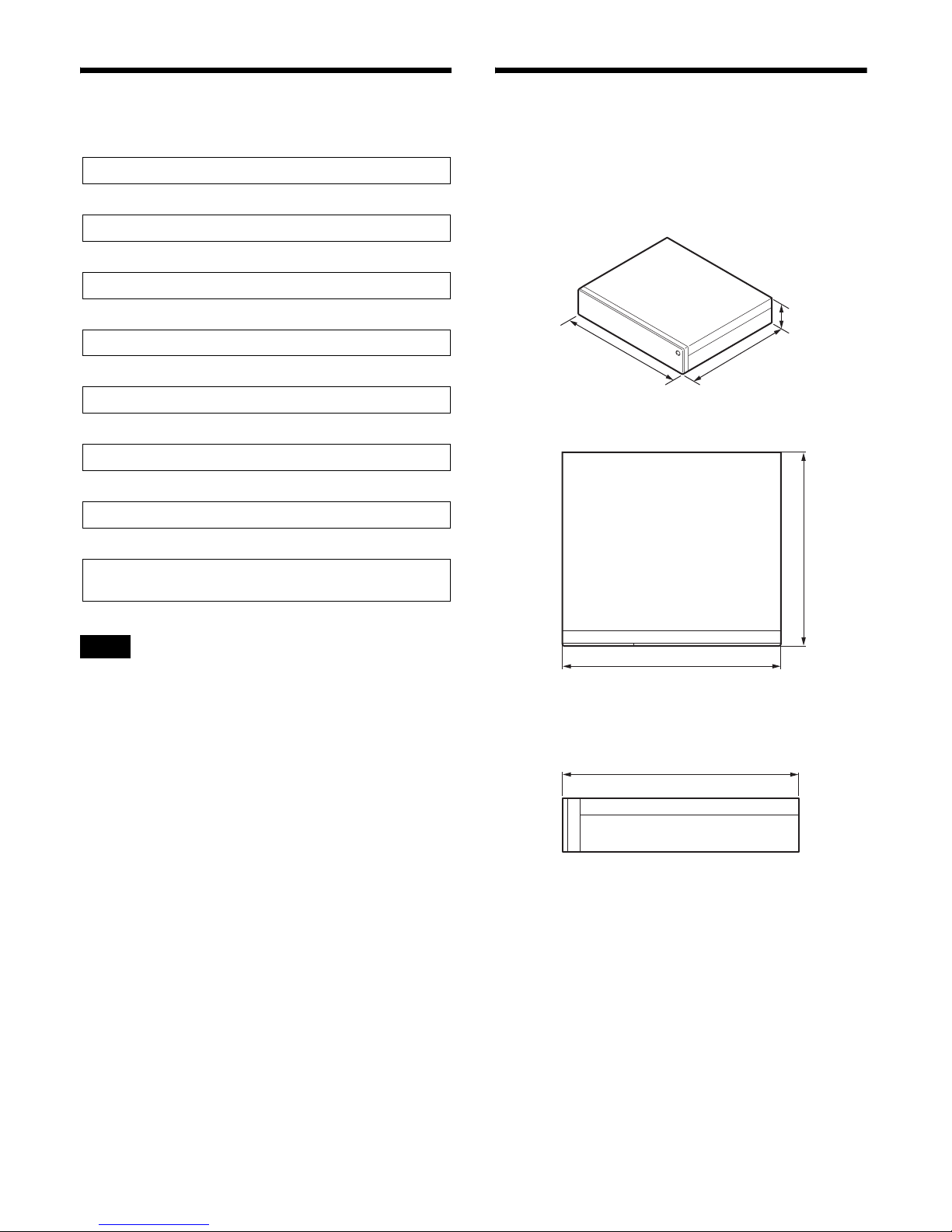
Step 1: Installation
Before setting up, be sure that the location for installation
provides sufficient space and strength to support the unit.
For the unit weight, see “Specifications” (page 59).
The dimensions for the unit are as follows.
Top
Side
When installing the unit on a rack, use the rack mount kit
designed specifically for this unit. For details on the rack
mount kit, contact your Sony dealer.
Note
Step 1: Installation (page 13)
r
Step 2: Installing the HDDs (page 14)
r
Step 3: Connections (page 16)
r
Step 4: System Settings (page 17)
r
Step 5: Verifying Operation (page 29)
r
Step 6: Activation (page 29)
r
Step 7: Data Backup (page 31)
r
For details on advanced settings, refer to the NVMS
Enterprise Edition Administrator Manual.
446 mm
(17
5
/8 in.)
410 mm
(16
1
/4 in.)
88.2 mm
(3
1
/2 in.)
446 mm (175/8 in.)
410 mm (16
1
/4 in.)
410 mm (161/4 in.)
14
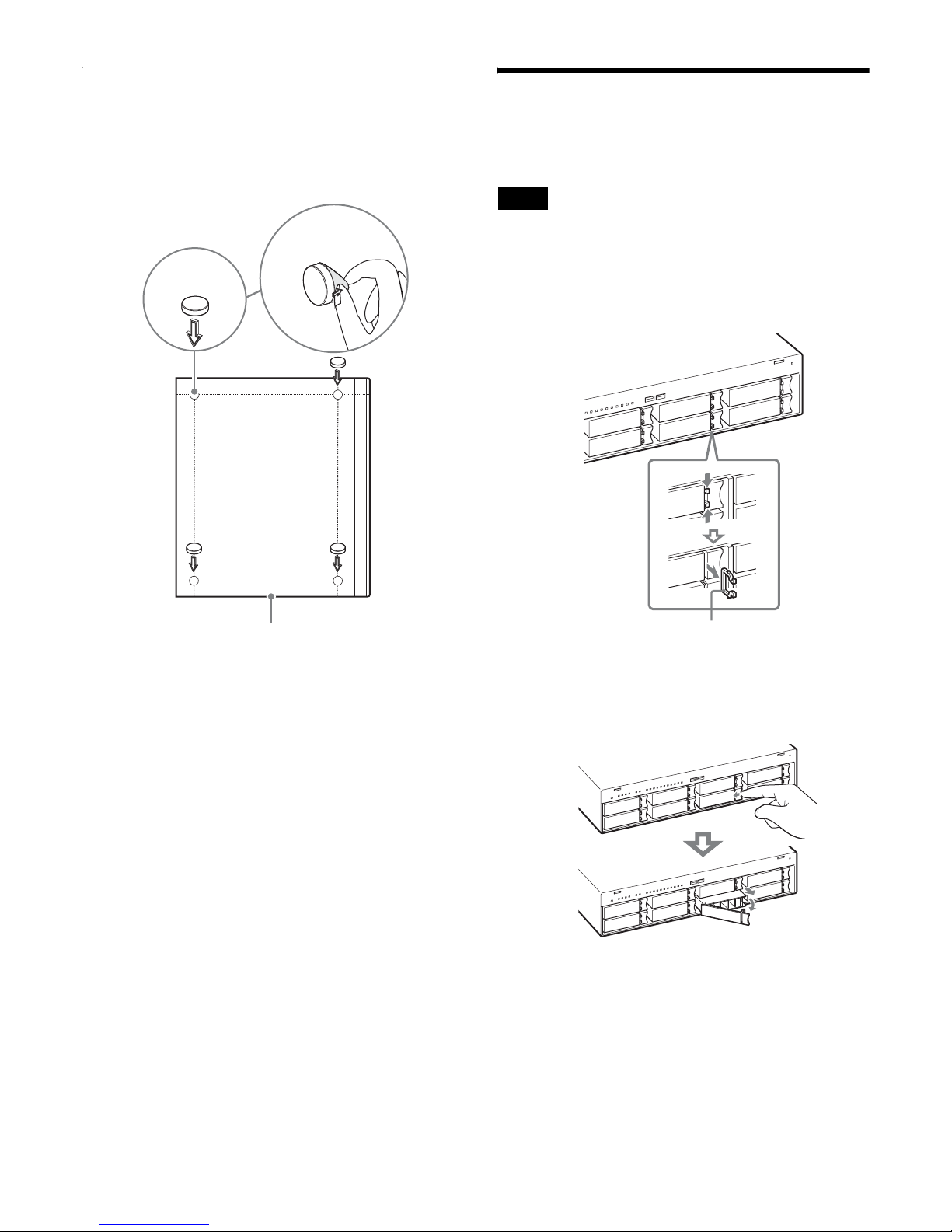
Installing without a Rack
Attach the provided rubber feet to the unit.
Place the unit upright so that the bottom surface is visible.
Then affix the adhesive surfaces of the rubber feet on the
bottom of the unit as illustrated below.
Step 2: Installing the
HDDs
The unit will not operate without an HDD installed.
1
Remove the HDD lock for the slot in which the HDD
will be installed.
To remove the HDD lock, push the tabs inward.
2
Remove the tray.
To unlatch the tray cover, insert your finger in the
indentation on the right and push inward.
Rubber foot
Remove the film
Bottom of the unit
Note
HDD lock
15
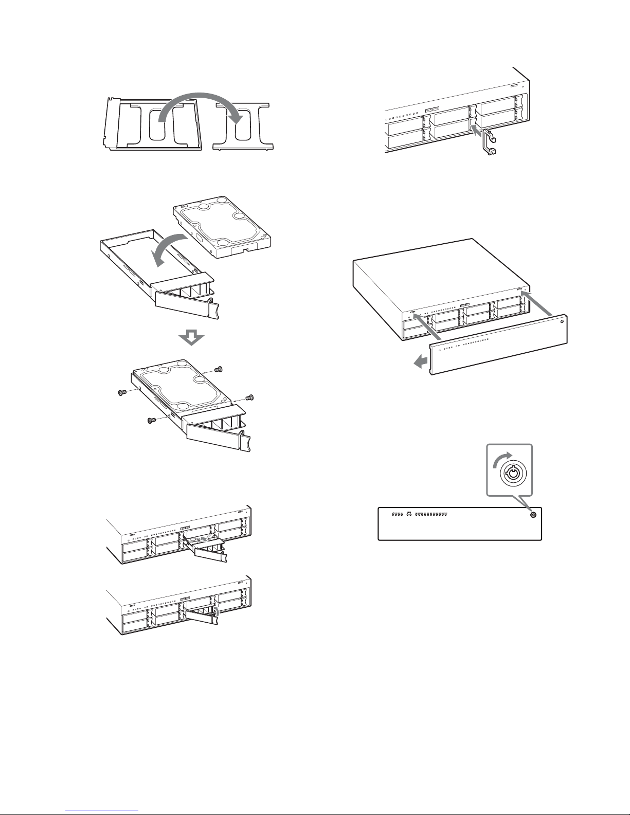
3
Remove the dummy HDD from the tray, set the actual
HDD into the tray in the direction illustrated, and
secure it using the four HDD screws (+K, UNC × 5).
4
Fully insert the tray in which the HDD is installed
into the slot, and lock it into place.
5
Reinsert the HDD lock removed in step 1.
6
Attach the front panel.
Insert the four tabs on the front panel into the
corresponding holes on the unit, and slide the panel to
the left.
7
Use the supplied front panel key to lock the front
panel.
Turn the front panel key 90 degrees clockwise.
16
Step 3: Connections
Connect each device to the unit.
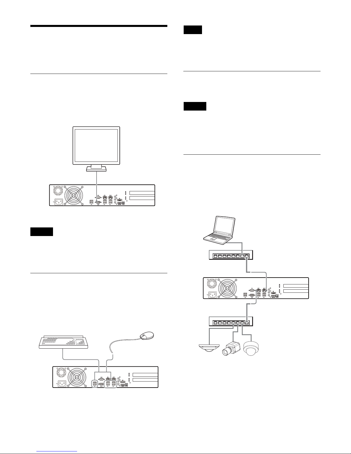
Connecting the Monitors
Connect the monitor to the monitor connector.
Example)
When monitors are connected via a monitor switch,
images may not always display. We recommend
connecting monitors directly to the unit.
Connecting the Keyboard and
Mouse
Connect the devices to the USB connectors on the unit.
Example)
When using USB devices, be sure to read “Precautions
for using USB devices” (page 5) in the “Usage
Precautions” section beforehand.
Connecting the Power Cord
Connect the power cord to the power supply connector.
Before installing, carefully read the Safety Regulations
(leaflet). When using the unit in combination with
multiple HAW units, make sure that the power supply is
sufficient.
Connecting to a Network
Connect to the network as follows.
Example)
Caution
Monitor
Monitor connector
Mouse
Keyboard
USB connectors
Note
Caution
Network hub
LAN connector 1
Network cameras
Connect LAN connector 1 to the same
network as the network cameras.
Remote client
Connect LAN connector 2 to the same network as the
Windows PC being used as the remote client.
Network hub
LAN connector 2
Smart Client
17
Connecting Other Devices
Connecting an audio output device
Connect the audio output device to the line output
connector.
Example)
Step 4: System Settings
This section describes how to turn on the power and the
basic procedure for registering cameras and other
devices.
Registering the Software License
Code (SLC) and Acquiring the
License File
Acquire a software license file using the SLC found on
the rear panel of the unit. For details, refer to the NVMS
License Guide.
When configuring a system with multiple Network Video
Recorders, the device licenses associated with each SLC
must be transferred to a single SLC to form a single
software license. For details on transferring device
licenses, refer to the NVMS License Guide.
Verifying the Software Version
Verify that the latest software is installed on the unit, and
update the software if it is older.
For systems with multiple Network Video Recorders, the
same version of the software must be running on all the
Network Video Recorders.
Audio cable
AUDIO OUT connector
Note
Note
SN: 1234567
SLC:
123-456-789-ab-cdefgh-ijkl
Ver.: 1234
18
1
Verify the version indicated on the rear panel of the
unit.
2
Verify the latest version.
Download the “NVMS Enterprise Edition
Installation Image Release Note” from the following
URL, and verify the software version.
https://www.sony.net/CameraSystem/NVMS/
Software
3
If the version of the software installed on the unit is
older, perform a clean installation of the software and
acquire the license file for the latest version.
For details on clean installation, refer to the NVMS
Enterprise Edition Maintenance Guide. For details
on acquiring the license file for the latest version,
refer to the NVMS License Guide.
Adding Device Licenses
Purchase and add licenses to increase the maximum
number of devices that can be registered. The additional
purchased licenses must also be applied to the unit’s
license. For details on applying the additional licenses,
refer to the NVMS License Guide.
For details on purchasing additional licenses, contact
your Sony dealer.
Installing the Management Server
on a Computer
When configuring a system with two or more Network
Video Recorders, the management server must be
installed on a computer separate from the Network Video
Recorders. Download the latest version of NVMS
Enterprise Edition for NVR from the following URL, and
install it on your computer.
https://www.sony.net/CameraSystem/NVMS/
Software
For details on installation, refer to the NVMS Enterprise
Edition Administrator Manual.
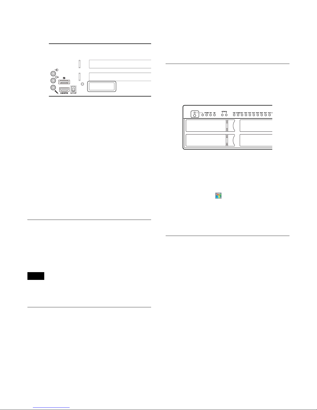
Turning On the Unit
When you remove the unit’s front panel and press the
power switch, the unit turns on and the POWER LED
lights blue.
When the unit is turned on for the first time, initial setup
for Windows will start. Proceed to the next section,
“Initial Setup for Windows.”
Turning off the unit
Click the Start button ( ) on the left side of the taskbar,
and click [Shutdown] in the menu that appears.
Alternatively, if you press the power switch, the unit will
start the shutdown procedure and turn off after a few
minutes.
Initial Setup for Windows
When the following setup wizard appears after turning on
the unit, perform the following.
1
Select the system language, and click [Next].
2
Select you country or region, time and currency,
keyboard layout, and click [Next].
3
Enter the user name and computer name that will be
used for login, and click [Next].
4
Enter the user password and password hint, and click
[Next].
Enter the password twice for confirmation.
Enter a word or phrase that will remind you of your
password for the password hint.
Note
SN: 1234567
SLC:
123-456-789-ab-cdefgh-ijkl
Ver.: 1234
 Loading...