

Sony HARD-1000 Service manual
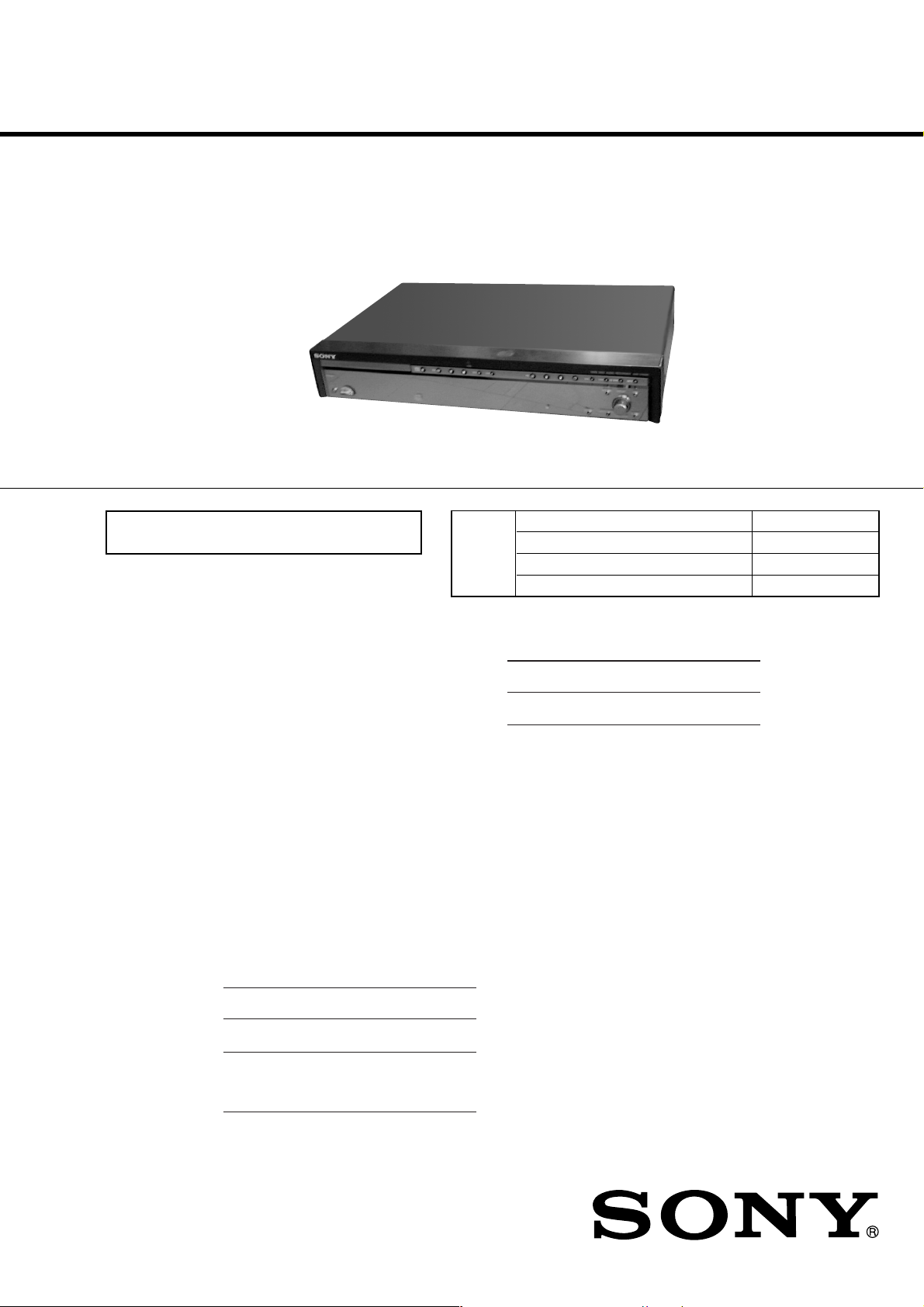
HAR-D1000
SERVICE MANUAL
Ver 1.2 2002. 03
US and foreign patents licensed from Dolby
Laboratories Licensing Corporation.
CD player section
System Compact disc and digital
Laser Semiconductor laser
Frequency response 5 Hz – 20 kHz (±0.5 dB)
Signal-to-noise ratio More than 95 dB
Wow and flutter Below measurable limit
HDD section
Capacity 40 GB
Recording system ATRAC 3
Transfer rate 132 kbps
Maximum recording time About 600 h
Maximum number of albums
Maximum number of tracks
Maximum number of tracks per album
Maximum CD-HDD ripping speed
Input
Jack
type
ANALOG
IN
DIGITAL
OPTICAL
IN
Phono
jacks
Square
optical
connector
jack
audio system
(λ = 780 nm)
Emission duration:
continuous
500
20,000
400
Max. ×2
Input
impedance
47 kilohms
Optical
wave length:
660 nm
Rated
input
500 mVrms
—
CD
Section
SPECIFICATIONS
Output
ANALOG
OUT
General
Power requirements
US and Canadian model : 120 V AC, 60 Hz
European model : 230 V AC, 50/60 Hz
Power consumption 25 W
Dimensions (Approx.) (w/h/d)
Mass (Approx.) 3.9 kg
Supplied accessories
Audio connecting cord (2)
Remote commander (remote) (1)
Sony R6 (size AA) battery (2)
USB cable (1)
“M-crew for HAR-D1000” CD-ROM(1)
“M-crew for HAR-D1000” operating instructions(1)
Minimum
input
125 mVrms
—
Design and specifications are subject to change
without notice.
US Model
Canadian Model
AEP Model
Model Name Using Similar Mechanism MXD-D4
CD Mechanism Type CDM55B-21BD53
Base Unit Name BU-21BD53
Optical Pick-up Name OP Assy (A-MAX.2)
Jack type
Phono
jacks
Rated
output
2 Vrms (at
50 kilohms)
430 × 82.5 × 285 mm
incl. projecting parts and
controls
Load
impedance
Over
10 kilohms
9-873-306-03
2002C1600-1
© 2002.03
HARD DISC AUDIO RECORDER
Sony Corporation
Home Audio Company
Published by Sony Engineering Corporation
HAR-D1000
r
Ver 1.2 2002.03
SAFETY CHECK-OUT
After correcting the original service problem, perform the following
safety check before releasing the set to the customer:
Check the antenna terminals, metal trim, “metallized” knobs, screws,
and all other exposed metal parts for AC leakage.
Check leakage as described below.
LEAKAGE TEST
The AC leakage from any exposed metal part to earth ground and
from all exposed metal parts to any exposed metal part having a
return to chassis, must not exceed 0.5 mA (500 microamperes.).
Leakage current can be measured by any one of three methods.
1. A commercial leakage tester, such as the Simpson 229 or RCA
WT -540A. Follo w the manufacturers’ instr uctions to use these
instruments.
2. A battery-operated AC milliammeter . The Data Precision 245
digital multimeter is suitable for this job.
3. Measuring the voltage drop across a resistor by means of a
VOM or battery-operated AC v oltmeter. The “limit” indication
is 0.75 V, so analog meters must hav e an accurate lo w-v oltage
scale. The Simpson 250 and Sanwa SH-63Trd are e xamples of
a passive VOM that is suitable. Nearly all battery operated
digital multimeters that have a 2 V A C range are suitable. (See
Fig. A)
To Exposed Metal
Parts on Set
CAUTION
Use of controls or adjustments or performance of procedures
other than those specified herein may result in hazardous
radiation exposure.
Notes on chip component replacement
•Never reuse a disconnected chip component.
• Notice that the minus side of a tantalum capacitor may be damaged by heat.
Flexible Circuit Board Repairing
•Keep the temperature of the soldering iron around 270 ˚C during repairing.
• Do not touch the soldering iron on the same conductor of the
circuit board (within 3 times).
• Be careful not to apply force on the conductor when soldering
or unsoldering.
SAFETY-RELATED COMPONENT WARNING!!
COMPONENTS IDENTIFIED BY MARK 0 OR DOTTED LINE WITH
MARK 0 ON THE SCHEMATIC DIAGRAMS AND IN THE PARTS
LIST ARE CRITICAL TO SAFE OPERATION. REPLACE THESE
COMPONENTS WITH SONY PARTS WHOSE PART NUMBERS
APPEAR AS SHOWN IN THIS MANUAL OR IN SUPPLEMENTS
PUBLISHED BY SONY .
1.5 k
0.15 µF
Fig. A. Using an AC voltmeter to check AC leakage.
The laser component in this product
is capable of emitting radiation
exceeding the limit for Class 1.
This appliance is classified as a CLASS 1
LASER product. The CLASS 1 LASER
PRODUCT MARKING is located on the
rear exterior.
Ω
Earth Ground
AC
voltmete
(0.75 V)
ATTENTION AU COMPOSANT AYANT RAPPORT
À LA SÉCURITÉ!
LES COMPOSANTS IDENTIFÉS P AR UNE MARQUE 0 SUR LES
DIAGRAMMES SCHÉMA TIQUES ET LA LISTE DES PIÈCES SONT
CRITIQUES POUR LA SÉCURITÉ DE FONCTIONNEMENT. NE
REMPLACER CES COMPOSANTS QUE PAR DES PIÈSES SONY
DONT LES NUMÉROS SONT DONNÉS DANS CE MANUEL OU
DANS LES SUPPÉMENTS PUBLIÉS PAR SONY.
The following caution label is located
inside of the unit.
2

TABLE OF CONTENTS
HAR-D1000
1. SERVICING NOTES
······················································· 4
2. GENERAL ·········································································· 7
3. DISASSEMBLY
3-1. Loading Panel ································································ 8
3-2. Case ··············································································· 9
3-3. Front Panel Assy···························································· 9
3-4. SUB Board, Main Board ············································· 10
3-5. Power Board ································································ 10
3-6. Hard Disk ···································································· 11
3-7. CD Mechanism Deck (CDM55B-21BD53) ················ 11
3-8. Holder (BU) Assy ························································ 12
3-9. OP Base Unit (BU-21BD), Holder (55-BU21) ···········12
3-10. Loading Board ···························································· 13
3-11. CAM (CDM55)··························································· 13
4. TEST MODE ···································································· 14
5. ELECTRICAL ADJUSTMENTS
CD Section ··········································································· 19
6. DIAGRAMS
6-1. Note For Printed Wiring Boards and
Schematic Diagrams···················································· 21
6-2. Block Diagram – HDD/SUB Section – ······················ 23
6-3. Block Diagram – Main Section – ······························· 24
6-4. Block Diagram – Display/Power Supply Section – ···25
6-5. Schematic Diagram – BD Section – ··························· 26
6-6. Printed Wiring Board – BD Section – ························ 27
6-7. Schematic Diagram – Main (1/4) Section – ··············· 28
6-8. Schematic Diagram – Main (2/4) Section – ··············· 29
6-9. Schematic Diagram – Main (3/4) Section – ··············· 30
6-10.Schematic Diagram – Main (4/4) Section – ··············· 31
6-11.Printed Wiring Board – Main (Side A) Section –······· 32
6-12.Printed Wiring Board – Main (Side B) Section – ······· 33
6-13.Schematic Diagram – Panel Section – ······················· 34
6-14.Printed Wiring Board – Panel Section –····················· 35
6-15.Schematic Diagram – SUB (1/2) Section – ················ 36
6-16.Schematic Diagram – SUB (2/2) Section – ················ 37
6-17.Printed Wiring Board – SUB (Side A) Section – ·······38
6-18.Printed Wiring Board – SUB (Side B) Section – ······· 39
6-19.Schematic Diagram – Power Section – ······················ 40
6-20.Printed Wiring Board – Power Section – ··················· 41
6-21.IC Block Diagrams ······················································ 42
6-22.IC Pin Function Descriptions ······································ 44
7. EXPLODED VIEWS
7-1. Case Section ································································ 54
7-2. Flont Panel Section ······················································ 55
7-3. Chassis Section ···························································· 56
7-4. CD Mechanism Deck Section ·····································57
8. ELECTRICAL PARTS LIST ······································· 58
3
HAR-D1000
d
Ver 1.1 2001.12
SECTION 1
SERVICING NOTES
NOTES ON HANDLING THE OPTICAL PICK-UP
BLOCK OR BASE UNIT
The laser diode in the optical pick-up block may suffer electrostatic
break-down because of the potential difference generated by the
charged electrostatic load, etc. on clothing and the human body.
During repair, pay attention to electrostatic break-down and also
use the procedure in the printed matter which is included in the
repair parts.
The flexible board is easily damaged and should be handled with
care.
For CD
NOTES ON LASER DIODE EMISSION CHECK
The laser beam on this model is concentrated so as to be focused on
the disc reflective surface by the objective lens in the optical pickup block. Therefore, when checking the laser diode emission,
observe from more than 30 cm away from the objective lens.
LASER DIODE AND FOCUS SEARCH OPERATION
CHECK
Carry out the “S curve check” in “CD section adjustment” and check
that the S curve waveforms is output three times.
MODEL IDENTIFICATION
— BACK PANEL —
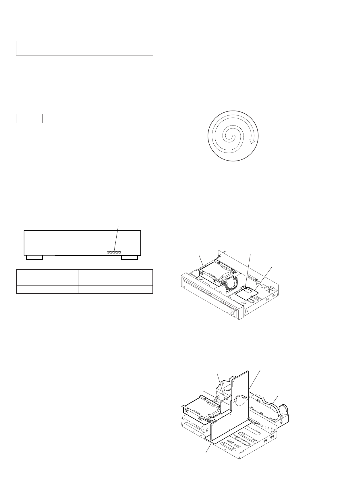
CLEANING OBJECTIVE LENS OF OPTICAL PICK-UP
• In cleaning the objective lens of optical pick-up, be sure the
following below.
1. In cleaning the lens, do not apply an excessive force.
As the optical pick-up is vulnerable, application of excessive
force could damage the lens holder.
2. In cleaning, do not use a cleaner other than exclusive cleaning
liquid (KK-91 or isopropyl alcohol).
3. Wipe the objective lens spirally from center toward outside.
(See Figure A)
(Figure A)
4. Eject the disk, if loaded.
5. Disconnect the power cord from the socket to shut off the power
supply.
6. When cleaning the objective lens of optical pick-up in CD,
refer to “HOLDER (BU) ASSY” on page 12.
Part No.
Model Part No.
US model 4-236-498-0s
AEP model 4-236-498-1s
NOTES ON HARD DISC
The hard disc has a high storage density and reads or writes data in
a short time with compared to the floppy disk. On the other hand, it
may be easily damaged by mechanical vibration, shock or dust.
Keep the hard disc away from magnets.
Although the hard disc has safety devices to prevent losing data due
to mechanical vibration, shock or dust, you should be careful when
handling the recorder. Avoid damaging your data:
• Do not cause a shock or strong vibration to the recorder.
• Do not place the recorder in a location subject to mechanical
vibration or in unstable location.
• Do not move the recorder while the power is on.
• Do not turn off the recorder while the HDD indicator lights up
blue.
• Do not use the recorder in a place subject to extreme changes in
temperature (temperature gradient less than 18 °F (10 °C)/ hour).
• Keep any magnetic objects, including a TV set, speaker, magnet,
and magnetic bracelet, away from the recorder.
JIG FOR CHECKING MAIN BOARD SIDE A
JIG
hard disk
Note: Please refer to “3-6. HARD DISK” of page 11 SECTION 3
DISASSEMBLY about how to remove a hard disk.
JIG FOR CHECKING SUB BOARD SIDE B AND
MAIN BOARD SIDE B
SUB board
JIG
(J-2501-202-A)
(J-2501-202-A)
SUB boar
MAIN board
JIG
(J-2501-091-A)
If the hard disc is damaged, data cannot be restored or recovered.
4
insulated sheet
HAR-D1000
CD SECTION
• In checking the CD block and MAIN board, prepare jig.
• In checking the CD block, prepare jig (extension cable J-2501-075-A) to connect the BD (CD) board (CN101) and MAIN board
(CN302).
• In checking the MAIN board, prepare jig (extension cable J-2501-094-A) to connect the MAIN board (CN305) and DISPLAY board
(CN951).
CD-TEXT TEST DISC
This unit is able to display the test data (character information) written in the CD on its fluorescent indicator tube.
The CD-TEXT TEST DISC (TGCS-313:4-989-366-01) is used for checking the display.
To check, perform the following procedure.
Checking Method:
1. Turn ON the power, set the disc to the disc table with the “test disc” label facing up, and chuck the disc.
2. Press the H (CD) button and play back the disc.
3. The following will be displayed on the fluorescent indicator tube.
Display : 1KHZ
4. Rotating [ALBUM] knob, select the track. The text data of each track will be displayed.
For details of the displayed contents for each track, refer to “Table 1 : CD-TEXT TEST DISC TEXT Data Contents” and “Table 2 : CDTEXT TEST DISC Recorded Contents and Display”.
0DB
Restrictions in CD-TEXT Display
In this unit, some special characters will not be displayed properly . These will be displayed as a space or a character resembling it. For details,
refer to “Table 2 : CD-TEXT DISC Recorded Contents and Display”.
Table 1 : CD-TEXT TEST DISC TEXT Data Contents (TRACKS No. 1 to 41:Normal Characters)
TRACK
No.
1 1kHz/0dB/L&R 22 1kHz/–90dB/L&R
2 20Hz/0dB/L&R 23 Infinity Zero w/o emphasis//L&R
3 40Hz/0dB/L&R 24 Infinity Zero with emphasis//L&R
4 100Hz/0dB/L&R 25 400Hz+7kHz(4:1)/0dB/L&R
5 200Hz/0dB/L&R 26 400Hz+7kHz(4:1)/–10dB/L&R
6 500Hz/0dB/L&R 27 19kHz+20kHz(1:1)/0dB/L&R
7 1kHz/0dB/L&R 28 19kHz+20kHz(1:1)/–10dB/L&R
8 5kHz/0dB/L&R 29 100Hz/0dB/L*
9 7kHz/0dB/L&R 30 1kHz/0dB/L*
10 10kHz/0dB/L&R 31 10kHz/0dB/L*
11 16kHz/0dB/L&R 32 20kHz/0dB/L*
12 18kHz/0dB/L&R 33 100Hz/0dB/R*
13 20kHz/0dB/L&R 34 1kHz/0dB/R*
14 1kHz/0dB/L&R 35 10kHz/0dB/R*
15 1kHz/–1dB/L&R 36 20kHz/0dB/R*
16 1kHz/–3dB/L&R 37 100Hz Squer Wave//L&R
17 1kHz/–6dB/L&R 38 1kHz Squer Wave//L&R
18 1kHz/–10dB/L&R 39 1kHz w/emphasis/–0.37dB/L&R
19 1kHz/–20dB/L&R 40 5kHz w/emphasis/–4.53dB/L&R
20 1kHz/–60dB/L&R 41 16kHz w/emphasis/–9.04dB/L&R
21 1kHz/–80dB/L&R
Displayed Contents
TRACK
No.
Displayed Contents
Note: The contents of Track No. 1 to 41 are the same as those of the current TEST DISC-their titles are displayed.
5
HAR-D1000
Table 2: CD-TEXT TEST DISC Recorded Contents and Display
(In this unit, some special characters cannot be displayed. This is not a fault)
TRACK
No.
42
43
44
45
46
47
48
49
50
51
52
53
54
55
56
57
58
59
60
61
62
63
64
65
66
67
to
99
Recorded contents
! ” # $ % & ´ (21h to 27h)1kHz 0dB L&R
( ) + , – . / (28h to 2Fh)
*
01234567 (30h to 37h)
8 9 : ; < = > ? (38h to 3Fh)
@A B C D E F G (40h to 47h)
H I J K L M N O (48h to 4Fh)
P QR S T U VW (50h to 57h)
X Y Z [ ¥ ] ^ _ (58h to 5Fh)
a b c d e f g (60h to 67h)
′
h i j k l m n o (68h to 6Fh)
p q r s t u v w (70h to 77h)
xyz{ I }
~
(78h to 7Fh)
i¢£¤¥ § (A0h to A7h) 8859-1
C ª¬PR–(A8h to AFh)
•±23
1
†
µ ¶• (B0h to B7h)
′
14123
º ¿ (B8h to BFh)
4
АБВГДЕЖЗ (C0h to C7h)
ИЙКЛМНОП (C8h to CFh)
D СТУФХЦ
ШЩЪЫЬY
˙
(D0h to D7h)
ß (D8h to DFh)
абвгдежз (E0h to E7h)
ийклмноп (E8h to FFh)
∂ стуфхц÷ (F0h to F7h)
шщъыьy ÿ (F8h to FFh)
´
No.66
No.67
to
No.99
Display
T All the same
T All the same
T All the same
T All the same
T All the same
T All the same
T All the same
T All the same
T All the same
T All the same
T All the same
T All the same
(A0h to A7h) 8859-1
(A8h to AFh)
(B0h to B7h)
(B8h to BFh)
AAAAAA C (C0h to C7h)
E E E E I I I I (C8h to CFh)
DNOOOOO (D0h to D7h)
O U U U U Y (D8h to DFh)
a a a a a a c (E0h to E7h)
eeeeiiii (E8h to EFh)
dnooooo (F0h to F7h)
o u u u u y y (F8h to FFh)
T All the same
T All the same
to
T All the same
6
SECTION 2
GENERAL
HAR-D1000
This section is extracted
from instruction manual.
Front Panel
12 3 456 87 9q;qaqs qd qfqg
HDD
HDD
DISPLAY
CDSYNC
MENU/NO
SEARCH/CHAR
INPUT
ALBUM YES
PUSH ENTER
OPEN/CLOSE A 3
Remote sensor wa
SEARCH/CHAR ql
STANDBY indicator 2
YES qh
BUTTON DESCRIPTIONS
@/1 (power) 1
STANDBY
?/1
ALBUM dial qk
CD SYNC qf
CD H 4
CD X 5
CD x 6
CD l/L 8
CLEAR qj
Disc tray wf
DISPLAY w;
OPEN/
AHXx HXxzlL lL
CD
CLOSE
Display wd
HDD indicator 7
HDD H 9
HDD X 0
HDD x qa
HDD l/L qd
HDD z qs
INPUT qg
MENU/NO ws
Rear Panel
CLEAR
Remote Control
1 / u
SELECT
wl
wk
wj
wh
wg
qhqjqkqlw;wawswf wd
HDDCD
INFO
PLAY MODE
REPEAT
DISPLAY SCROLL
MENU/NO
`-/,
123
GHI JKL MNO
456
PQRS TUV WXYZ
NAME EDIT
/ SELECT
ABC DEF
TIME
789
SEARCH
PLAY LIST
ALBUM
CLEAR
HIGH-
LIGHT
wf
wd
ws
>10 10/0
INPUT
REC-IT
wa
w;
CD SYNCHRO
ql
qk
qj
ALBUM - ALBUM +
LEVEL
><
qh
1
2
3
4
5
YES
6
7
8
9
q;
qa
qs
qd
qf
REC
qg
ANALOG
DIGITAL
CD CHANGER
USB
IN OUT OPTICAL
L
R
CONTROL
IN
312 4 5 6
ANALOG IN L/R jacks 1
ANALOG OUT L/R jacks 2
CD CHANGER CONTROL jack 4
DIGITAL OPTICAL IN connector 3
Power cord 6
USB connector 5
ALBUM 8
ALBUM +/– qk
CD SYNCHRO qd
CLEAR 0
DISPLAY wj
HIGH-LIGHT qa
INFO wk
INPUT wd
Letter/Numeric buttons 7
MENU/NO wg
NAME EDIT/SELECT wh
PLAY LIST ws
PLAY MODE 2
REC-IT wa
REC LEVEL +/– qg
REPEAT 3
SCROLL 4
SEARCH 9
SELECT wl
TIME 5
YES 6
BUTTON DESCRIPTIONS
@/1 (power) 1
H w;
X qs
x qf
./> qj
m/M qh
z ql
>10 wf
7
HAR-D1000
)
DISASSEMBLY
Note : Disassemble the unit in the order as shown below.
SECTION 3
Case
Case
Front panel section
Sub board, Main board
Power board
Hard disk
Holder (BU) assy
Loading board
OP base unit (BU-21BD), Holder (55-BU21
CAM (CDM55)
Set
Loading panel
CD mechanism deck
(CDM55B-21BD53)
Note : Follow the disassembly procedure in the numerical order given.
3-1. LOADING PANEL
2
1
To close the disc table, turn the tapering
∗
driver in the reverse direction (to IN direction).
3 Two claws
4 Loading
panel
8
3-2. CASE
)
)
1 Two screws
(CASE3 TP2)
HAR-D1000
2 Two screws
(CASE3 TP2)
4 CASE
3 Two screws
(CASE3 TP2
3-3. FRONT PANEL ASSY
5 Front panel assy
1 Wire (flat type) (18 core
(CN305)
4 Two
claws
2 Ground
3 Four screws
(BVTP 3 × 8)
9
HAR-D1000
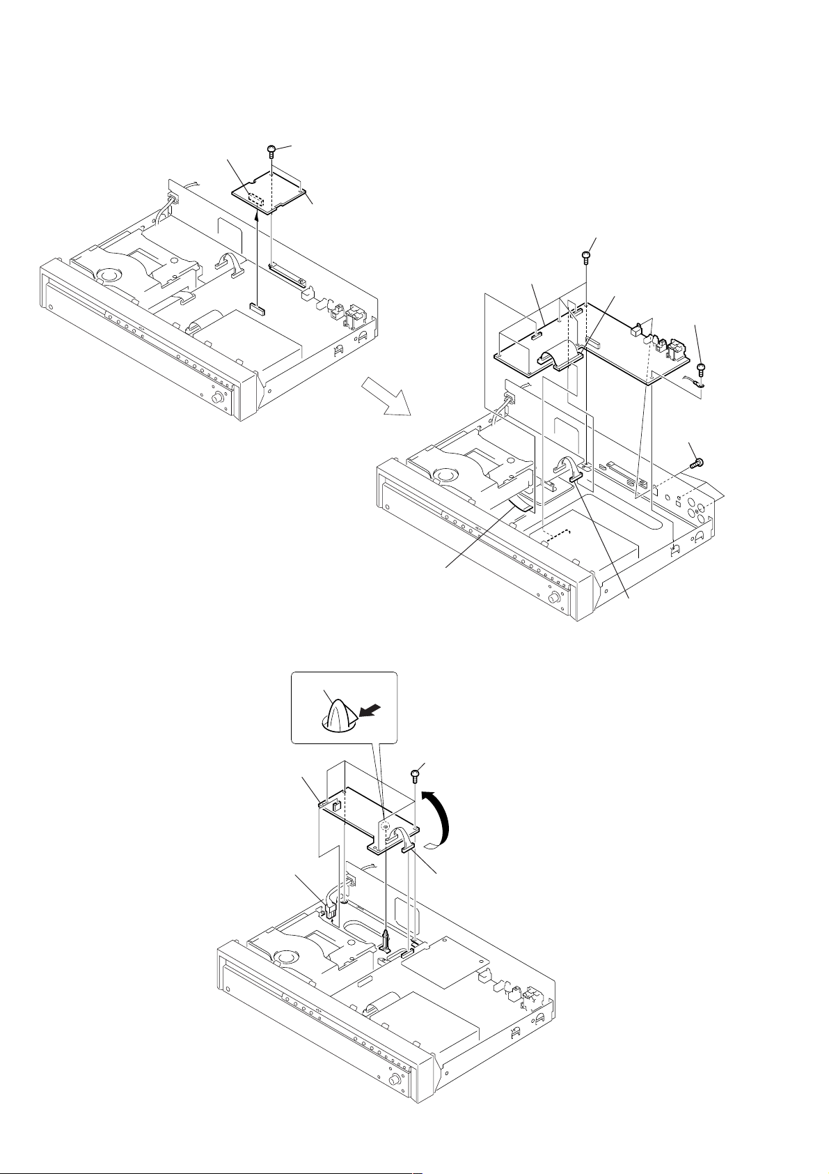
3-4. SUB BOARD, MAIN BOARD
2 Connecter
(CN901)
1 Two screws
(BVTP 3 × 8)
3 SUB board
7 MAIN board
4 Five screws
(BVTP 3 × 8)
3 Connecter
(CN101)
5 Screw
(BVTP 3 × 8)
6 Three screws
(BVTP 3 × 8)
3-5. POWER BOARD
4 PC board holder
5 POWER board
1 Connecter
(CN3101)
1 Wire (flat type)
(21 core) (CN302)
2 Connecter
(CN3103)
3 Four screws
(BVTP 3 × 8)
2 Connecter
(CN3103)
10
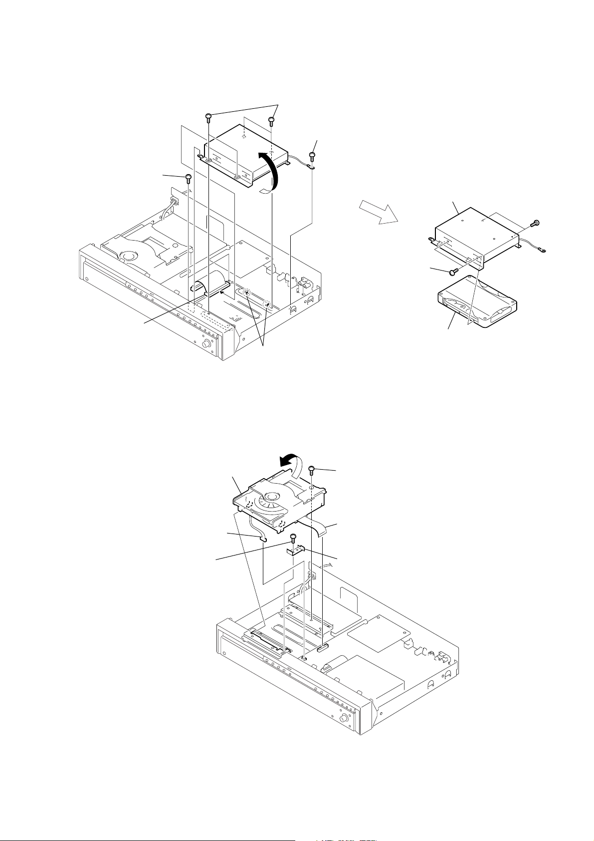
3-6. HARD DISK
2 Two screws
(BVTP 3 × 8)
HAR-D1000
4 Four screws
(BVTT 3 × 10)
3 Screw
(BVTP 3 × 8)
1 Connector
(CN101)
5 Two claws
3-7. CD MECHANISM DECK (CDM55B-21BD53)
6 CD mechanism deck
(
CDM55B-21BD53
)
6 Two screws
(3 × 4.5)
5 Screw
(BVTP 3 × 8)
8 Bracket (HDD)
9 Hard disk
7 Two screws
(3 × 4.5)
2 Connector
CN301
(
3 Screw
(BVTP 3 × 8)
)
1 Wire (flat type) (21 core)
(CN302)
4 Fitting plate (stopper)
11
HAR-D1000
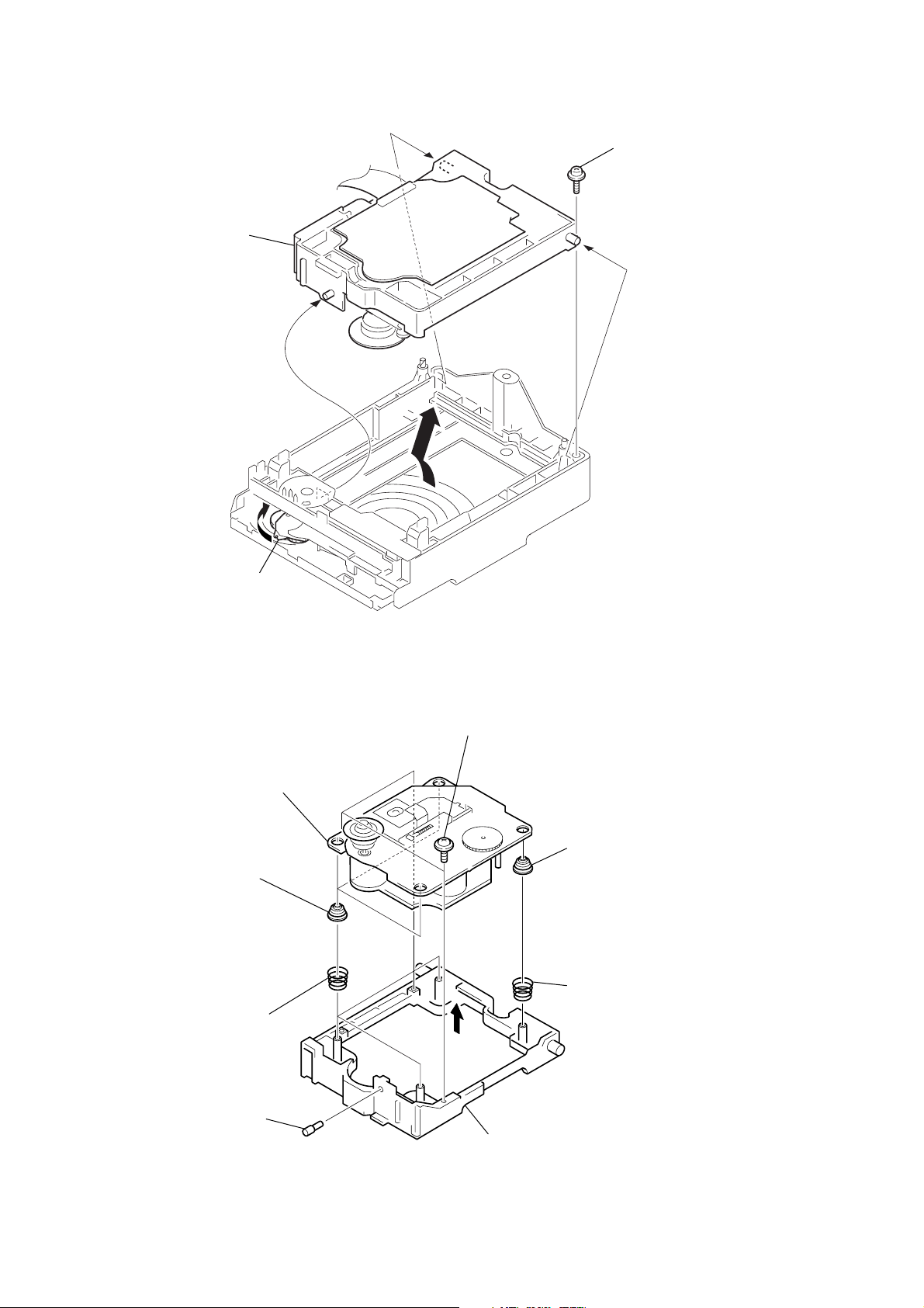
3-8. HOLDER (BU) ASSY
4 Holder (BU) assy
2 Floating screw
(PTPWH M2.6)
3
A
1 Rotate the lever (SW) in the
direction of the arrow A.
3-9. OP BASE UNIT (BU-21BD), HOLDER (55-BU21)
7 Base unit
(BU-21BD53)
3 Three insulators
(BU21)
1 Three floating screws
(DIA. 12)
5 Insulator (BU21)
12
4 Three cone
coil springs
8 Shaft (BU21)
6 Cone coil spring
2
9 Holder (55-BU21)
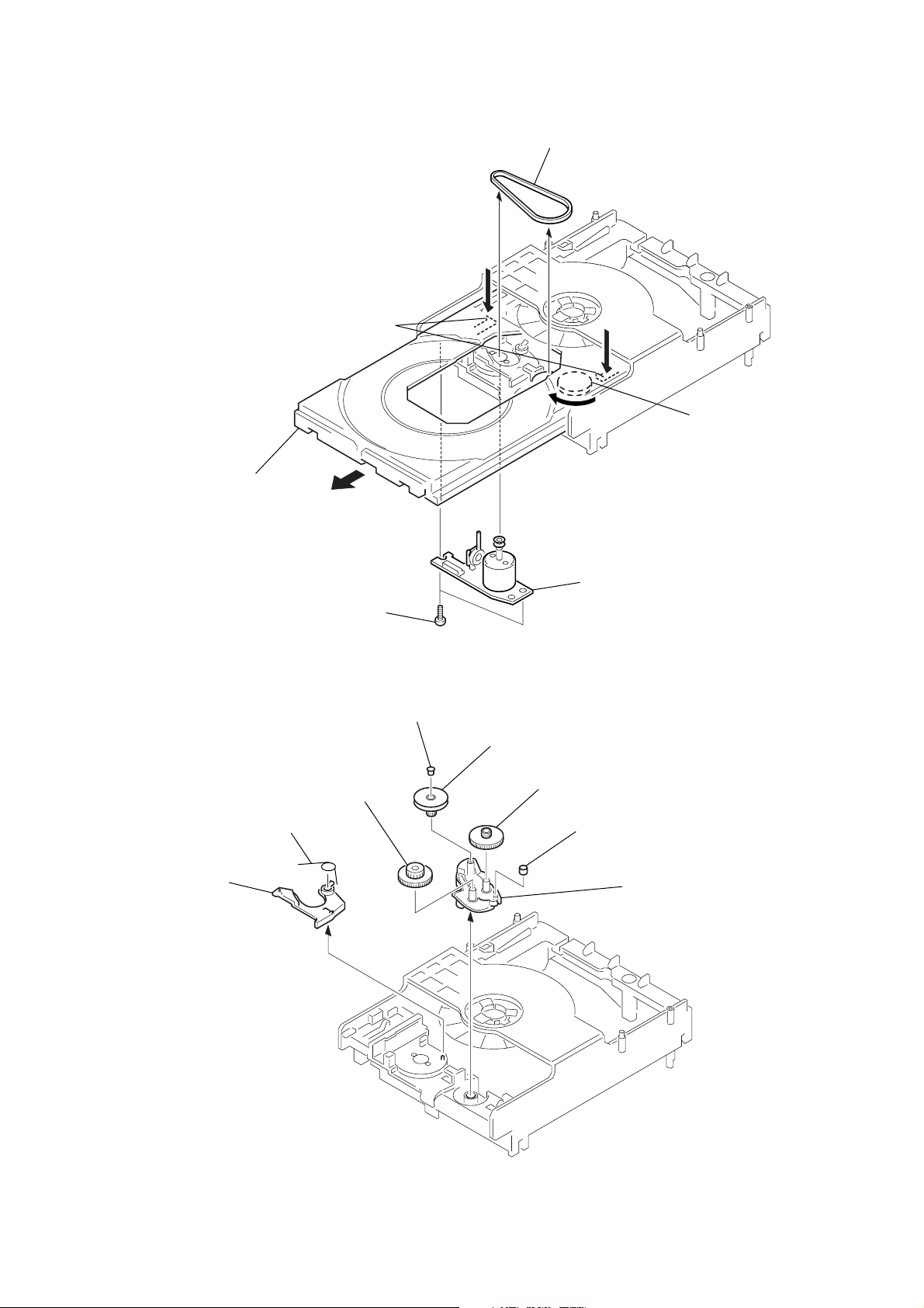
3-10. LOADING BOARD
)
2 Belt
(CDM55)
1 Rotate the gear (B) in
the direction of arrow
A.
5 Loading board
4 Two screws
(BTP 2.6 × 8)
3 Pull the tray pushing two claws.
Two claws
A
HAR-D1000
3-11. CAM (CDM55)
1 Torsion spring
2 Lever (SW)
6 Gear (B)
3 Spacer (55)
4 Pulley (LDG)
5 Gear (A)
7 Roller
8 Cam (CDM55
13
HAR-D1000
Ver 1.1 2001.12
SECTION 4
TEST MODE
This set provides various modes for the service.
Enter the test mode through the procedure given below, and select the desired mode.
Procedure:
1. Press the x (CD), x (HDD) and [YES] buttons at the same time.
2. Press the
3. At this time, turn the
4. To exit from the test mode, turn the
Contents of test mode
No. Display Function
0 <To Normal> 0 Exit from test mode
1 <Version> 1 Microcomputer Version display
2 <FLD> 2 FL display test & LED display test
3 <Key, Jog> 3 Key/Jog input test
4 <CD Test> 4 CD all sorts test
5 <HD Test> 5 HD all sorts test
6 <HD Aging> 6 HD aging
7 <Initial> 8 All reset (Not for Service)
8 <Sircs> 10 Sircs code mode (Not for Service)
9 <Dump> 11 Microcomputer Dump mode (Not for Service)
10 <CD Aging> 12 CD aging
11 <CD Ship> 16 Shipment mode (Not for Service)
[ALBUM] dial andx (HDD) button to display “<To Normal> 0”.
[ALBUM] dial can select all modes. For the contents of mode, see the following table.
[ALBUM] dial to display “<To Normal> 0”, then press the [ALBUM] dial.
CD Test Menu
Display Function
0> COMMAND Command transfer menu (Not for Service)
1> ERROR C1, C2 error display
2> SPEED X1 Disc speed selection
3> ISRC ISRC display (Not for Service)
4> CHECK8 Check 8 cm display (Not for Service)
5> AUTO G Auto gain display (Not for Service)
6> HENSHIN Decentiering display (Not for Service)
7> PORT Port selection (Not for Service)
8> AMS ON AMS ON/OFF display (Not for Service)
9> TRK ON TRK ON/OFF display
A> SJI (Not for Service)
HD Test Menu
Display Function
Format? Formatting the HD
Flash Init? Initialization of Flash
Read Test? Sector read test of the HD
Write Test? Sector write test of the HD
R/W Test? Sector write read and verify test of the HD
Smart? Display of S.M.A.R.T. status
14

HAR-D1000
Ver 1.1 2001.12
Microcomputer Version Display
Procedure:
1. Enter the test mode, then turn the [ALBUM] dial to display “<Version> 1”, and press the [ALBUM] dial.
2. The [MC] version is displayed, and then rotate the
The message <TA> version is displayed. Rotate the
3. Press the [ALBUM] dial to display [MMI] version.
4. Press the [ALBUM] dial to display [HD] version.
5. To exit from the mode, press the [ALBUM] dial.
FL Display Test/LED display test
Procedure:
1. Enter the test mode, then turn the [ALBUM] dial to display “<FLD> 2”, and press the [ALBUM] dial.
2. All segments of fluorescent display tube turn on fully, and LED (HDD) turn on.
3. Pressing the [ALBUM] dial cause almost half segments and LED (HDD) to turn off.
4. Press the [ALBUM] dial and the pattern of segments changes to another.
5. To exit from the mode, press the [ALBUM] dial.
Key/Jog Input Test
Procedure:
1. Enter the test mode, then turn the [ALBUM] dial to display “<Key, Jog> 3”, and press the [ALBUM] dial. The message “Key = 21” is displayed.
2. Clockwise rotation of the [ALBUM] dial moves the peak level meter up, or counterclockwise rotation of the [ALBUM] dial moves peak
level meter down.
3. Press the buttons in order and the number of Key decreases while turning off segments of fluorescent display tube. And when all buttons
were pressed, “Key OK!” will be displayed.
4. To exit from the mode, press the [ALBUM] dial.
[ALBUM] dial.
[ALBUM] dial again and <CD>, <CDM>, <DISP> and <TM> versions are displayed.
15

HAR-D1000
Ver 1.1 2001.12
CD SECTION
Set the CD test mode when performing confirmations (refer to page 5).
After completing confirmation, release the CD test mode.
1. C1, C2 ERROR DISPLAY
Procedure:
(1) Enter the CD test mode, then rotate the [ALBUM] dial to display “1> ERROR”, and press the [ALBUM] dial.
(2) C1 error and C2 error are displayed on the left side and right side with 4-digit codes respectively.
(3) To exit from this mode, press the [MENU/NO] button.
2. DISC SPEED SELECTION
Procedure:
(1) Enter the CD test mode, then rotate the [ALBUM] dial to display “2> SPEED ×1”, and press the [ALBUM] dial.
(2) Each time the [ALBUM] dial is pressed, the speed changes over such as ×1 t ×2 t ×4 t ×1.
(3) To exit from this mode, press the [MENU/NO] button.
3. TRK ON/OFF
Procedure:
(1) Enter the CD test mode, then rotate the [ALBUM] dial to display “9> TRK ON”, and press the [ALBUM] dial.
(2) Switch the tracking servo ON/OFF.
(3) To exit from this mode, press the [MENU/NO] button.
CD Aging Test
Procedure:
1. Set CD in the set.
2. Enter the test mode, then turn the [ALBUM] dial to display “<CD Aging> 12”, and press the [ALBUM] dial.
3. CD aging test starts with reading the first track, reading the last track, tray open, tray close and TOC reading.
4. The aging cycle is repeated.
5. To exit from this mode, press the x (CD) button.
6. Take out CD from the set.
16
HDD SECTION
Set the HD test mode when performing confirmation (refer to page 11).
After completing confirmation, release the HD test mode.
Note :
If any of the following test modes is executed, data is written in the HD.
Never execute any of these test modes on the customer's HD, because customer's data is erased during test mode.
1. FORMAT
4. WRITE TEST
5. R/W TEST
HD Aging Test
Note (When HD is replaced) :
When HD is replaced, perform the following steps.
(a) When HD is replaced, leave the set with the power on for approximately thirty minutes . (Warming up the HD)
(b) Enter the HD test mode and format the HD.
(c) Turn off the power once and back on again.
(d) Record the music in the HD using CD-HDD Synchro-Recording function for testing the HD. (about thirty minutes)
(e) Confirm that music is correctly recorded. After it is confirmed, erase all recordings on the HD.
HAR-D1000
Ver 1.1 2001.12
1. FORMAT
* This mode performs logical formatting HD. (about three minutes)
If formatting is performed, all data on the HD is erased.
* When HD is replaced, be sure to format the new HD. If the new HD is not formatted, the error message "Format Error " will be displayed.
* The 500 albums and 10 play lists are created at the same time of logical formatting FAT32 on the HD.
Procedure:
(1) Enter the HD test mode, then rotate the [ALBUM] dial to display “Format?”, and press the [ALBUM] dial to display “Format OK?”.
(2) The message “Format Now” is displayed and it takes about three minutes.
(3) When format is complete, “Format End” is displayed.
(4) To exit from this mode, press the [CLEAR] button.
2. FLASH INITIALIZATION
* The last memory (which is stored before power-off) is initialized to the default value of the factory setting.
Procedure:
(1) Enter the HD test mode, then rotate the [ALBUM] dial to display “Flash Init?”, and press the [ALBUM] dial.
(2) Initialization is performed and “OK” is displayed.
(3) To exit from this mode, press the [CLEAR] button.
Contents of the Last memory
Item Contents Default value
S.Space Setup Smart Space ON/OFF ON
L.Sync Setup Level Syncro ON/OFF ON
INPUT CD/OPT/ANALOG CD
L.Sync Th IDX Level-Sync THRESH value -50dB
DIG VOL CD CD digital volume dB value 0.0dB
DIG VOL OPT OPT digital volume dB value 0.0dB
DIG VOL ANLG ANALOG digital volume dB value 0.0dB
1/ALL Play mode of ALBUM ALL
PLAY MODE Play mode CONTINUE
REP MODE Repeat mode OFF
Display Mode Time Display mode Total playing time
Current Album No. The present Album Number 1
Text Save Setup TEXT SAVE ON/OFF ON
Sync Mode Setup Normal/High/Changer Normal
17

HAR-D1000
Ver 1.1 2001.12
3. READ TEST
* This mode needs not be performed in normal operation.
* Perform this mode only for the newly formatted HD.
Procedure:
(1) Enter the HD test mode, then rotate the
“OUT” or “THRU” is also selectable by rotating the
(2) Press the [ALBUM] dial and “Testing xx %” is displayed during the read test.
(3) When the read test is good, “OK” will be displayed.
(4) To exit from this mode, press the [CLEAR] button.
* “THRU” test takes very long time.
4. WRITE TEST
* This mode needs not be performed in normal operation.
* Perform this mode only for the newly formatted HD.
Procedure:
(1) Enter the HD test mode, then rotate the [ALBUM] dial to display “Write Test?”, and press the [ALBUM] dial to display “IN”. “MID”,
“OUT” or “THRU” is also selectable by rotating the [ALBUM] dial.
(2) Press the [ALBUM] dial and “Testing xx %” is displayed during the write test.
(3) When the write test is good, “OK” will be displayed.
(4) To exit from this mode, press the [CLEAR] button.
* “THRU” test takes very long time.
[ALBUM] dial to display “Read Test?”, and press the [ALBUM] dial to display “IN”. “MID”,
[ALBUM] dial.
5. R/W TEST
* Perform the R/W TEST when checking the formatted HD.
* Confirmation is normally satisfied by each performing IN, MID and OUT sector test.
Procedure:
(1) Enter the HD test mode , then rotate the [ALBUM] dial to display “R/W Test?”, and press the [ALBUM] dial to display “IN”. “MID”,
“OUT” or “THRU” is also selectable by rotating the [ALBUM] dial.
(2) Press the [ALBUM] dial and “Testing xx %” is displayed during the R/W test.
(3) When the R/W test is good, “OK” will be displayed.
(4) To exit from this mode, press the [CLEAR] button.
* “THRU” test takes very long time.
6. SMART TEST
* This mode displayed status of S.M.A.R.T. functions of the HD.
* If "NG" appears in this mode, the HD may be damaged in the near future. Replacement of the HD is recommended.
Procedure:
(1) Enter the HD test mode, then rotate the [ALBUM] dial to display “Smart?”, and press the [ALBUM] dial.
(2) When the test is complete, “OK” or “NG” is displayed.
(3) To exit from this mode, press the [CLEAR] button.
HD Aging Test
* This mode needs not be performed in normal operation.
* Perform this mode only for the newly formatted HD.
Procedure:
1. Enter the test mode, then turn the [ALBUM] dial to display “< HD Aging > 6”, and press the [ALBUM] dial.
2. Tracks of 4 seconds are created automatically.
3. To exit this mode, press the x (HDD) button.
4. Execute “<Initial> 8” (All reset) of the test mode.
18
SECTION 5
e
e
+
–
BD board
TP (TE)
TP (VC)
oscilloscope
(DC range)
ELECTRICAL ADJUSTMENTS
HAR-D1000
Ver 1.1 2001.12
CD SECTION
Note:
1. CD Block is basically designed to operate without adjustment.
Therefore, check each item in order given.
2. Use YEDS-18 disc (3-702-101-01) unless otherwise indicated.
3. Use an oscilloscope with more than 10MΩ impedance.
4. Clean the object lens by an applicator with neutral detergent when the
signal level is low than specified value with the following checks.
5. Level doesn’t change whiche ver with normal speed or with four times
speed.
S Curve Check
Connection:
BD board
TP (FE)
TP (VC)
Procedure:
1. Connect oscilloscope to test point TP (FE) and TP (VC) on
BD board.
2. Turn ON the power.
3. Put disc (YEDS-18) in and turned Power switch on again and
actuate the focus search. (actuate the focus search when disc
table is moving in and out.)
4. Check the oscilloscope waveform (S-curve) is symmetrical
between A and B. And conf irm peak to peak le vel within 3.6 ±
0.5 Vp-p.
S-curve waveform
oscilloscop
(DC range)
+
–
symmetry
A
B
within 3.6
±
0.5 Vp-p
Note: A clear RF signal waveform means that the shape “◊” can be clearly
distinguished at the center of the waveform.
RF signal waveform
VOLT/DIV: 200 mV
TIME/DIV: 500 ns
level: 1.0
(normal speed)
±
0.2 Vp-p
Checking Location: BD board (see page 20)
E-F Balance Check
Connection:
Procedure:
1. Connect oscilloscpe to test point TP (TE) and TP (VC) on BD
board.
2. Turn ON the power.
3. Put disc (YEDS-18) in to play the number five track.
4. Press the [ALBUM] dial to display “9> TRK ON” at the CD
test mode. (The tracking servo and the sledding servo are turned
OFF)
5. Check the level B of the oscilliscope's waveform and the A
(DC voltage) of the center of the Traverse waveform.
Confirm the following :
A/B x 100 = less than ± 22%
Traverse Waveform
Center of
the waveform
Note: • Try to measure several times to make sure than the ratio of A : B
or B : A is more than 10 : 7.
• Take sweep time as long as possible and light up the
brightness to obtain best waveform.
Check Location: BD board (see page 20)
RF Level Check
Connection:
oscilloscop
(AC range)
BD board
TP (RFDC)
TP (VC)
+
–
Procedure:
1. Connect oscilloscope to test point TP (RFDC) and TP (VC) on
BD board.
2. Turn ON the power.
3. Put disc (YEDS-18) in to play the number five track.
4. Confirm that oscilloscope waveform is clear and check RF
signal level is correct or not.
B
0V
level: 1.3 ± 0.6 Vp-p
A (DC
voltage)
6. Press the [ALBUM] dial. (The tracking servo and sledding servo
are turned ON)
Confirm the C (DC voltage) is almost equal to the A (DC
voltage) is step 5.
Traverse Waveform
0V
Tracking servo
Sled servo
OFF
Tracking servo
Sled servo
ON
C (DC
voltage)
Checking Location: BD board (see page 20)
19
HAR-D1000
Checking Location:
– BD BOARD (Side B) –
TP
(VC)
IC171
TP (TE)
TP (RFDC)
TP
(FE)
IC101
20
SECTION 6
d
DIAGRAMS
6-1. NOTE FOR PRINTED WIRING BOARDS AND SCHEMATIC DIAGRAMS
(In addition to this, the necessary note is printed in each block)
Note on Printed Wiring Board:
• X : parts extracted from the component side.
• Y : parts extracted from the conductor side.
a
•
•: Pattern from the side which enables seeing.
(The other layers' patterns are not indicated.)
Caution:
Pattern face side: Parts on the pattern f ace side seen from
(Side B) the pattern face are indicated.
Parts face side: Parts on the par ts face side seen from
(Side A) the parts face are indicated.
• Indication of transistor.
: Through hole.
C
Q
B
E
Q
B
CE
Q
B
CE
These are omitted.
These are omitted.
These are omitted.
Note on Schematic Diagram:
• All capacitors are in µF unless otherwise noted. p : pF
50 WV or less are not indicated except for electrolytics
and tantalums.
• All resistors are in Ω and 1/
specified.
f
•
• 5 : fusible resistor.
• C : panel designation.
• A : B+ Line.
• B : B– Line.
• H : adjustment for repair.
•Voltages are taken with a V OM (Input impedance 10 MΩ).
•Waveforms are taken with a oscilloscope.
• Circled numbers refer to waveforms.
• Signal path.
: internal component.
Note:
The components identified
by mark 0 or dotted line
with mark 0 are critical for
safety .
Replace only with part
number specified.
Voltage variations may be noted due to normal production tolerances.
Voltage variations may be noted due to normal production tolerances.
E : HDD PLAY
j : HDD REC
J : CD PLAY
l : DIGITAL IN
HAR-D1000
Ver 1.1 2001.12
4
W or less unless otherwise
Note:
Les composants identifiés par
une marque 0 sont critiques
pour la sécurité.
Ne les remplacer que par une
piéce portant le numéro spécifié.
Printed wiring board of BD board is shown only for referring, because CD base unit is replaced as a block.
• SUB boards is four-layer pritnted board.
However, the patterns of layer 2 and 3 hav e not been included in
this diagrams.
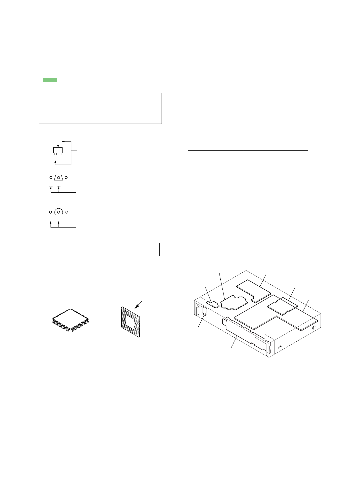
* Replacement of IC101 and IC401 used in this set requires a
special tool.
Lead layout of
conventional IC
* Replacement of IC101 and IC401 used in this set requires a
special tool.
• The voltage and wav eform of CSP (chip size pac kage) cannot be
measured, because its lead layout is different from that of
conventional IC.
CSP (chip size package)
surface
• Circuit Boards Location
BD board
LOADING
board
STAND-BY
board
PANEL board
POWER board
SUB board
MAIN boar
21
 Loading...