

Sony Handycam DCR-PC2E, RMT-812, RMT-809, Handycam DCR-PC3E Service Manual
DCR-PC2E/PC3E
RMT-809/812
AEP Model
UK Model
SERVICE MANUAL
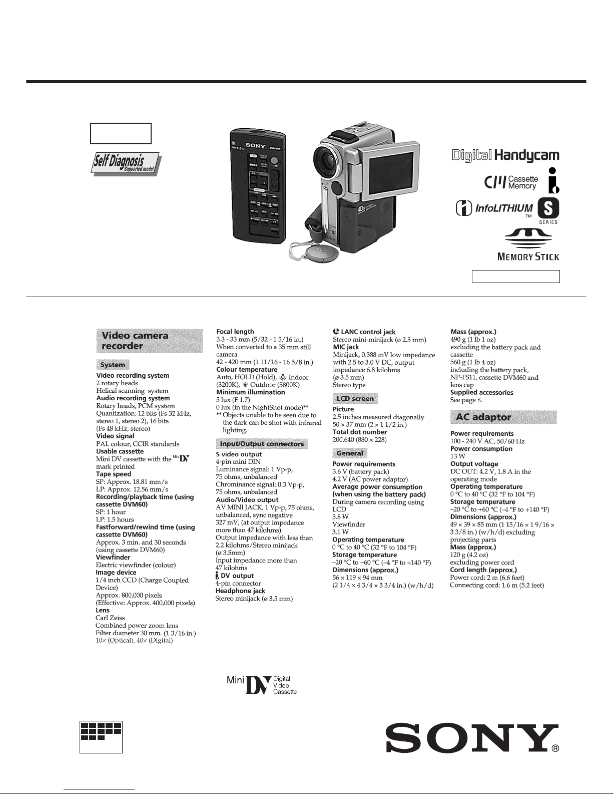
DIGITAL VIDEO CAMERA RECORDER
MICROFILM
D300 MECHANISM
Photo : DCR-PC3E
RMT-812
SPECIFICATIONS
Level 1
— Continued on next page —
Ver 1.0 1999. 06
— 2 —
SAFETY-RELATED COMPONENT WARNING!!
COMPONENTS IDENTIFIED BY MARK ! OR DO TTED LINE WITH
MARK ! ON THE SCHEMATIC DIAGRAMS AND IN THE PARTS
LIST ARE CRITICAL TO SAFE OPERATION. REPLACE THESE
COMPONENTS WITH SONY PARTS WHOSE PART NUMBERS
APPEAR AS SHOWN IN THIS MANUAL OR IN SUPPLEMENTS
PUBLISHED BY SONY .
1. Check the area of your repair for unsoldered or poorly-soldered
connections. Check the entire board surface for solder splashes
and bridges.
2. Check the interboard wiring to ensure that no wires are
"pinched" or contact high-wattage resistors.
3. Look for unauthorized replacement parts, particularly
transistors, that were installed during a previous repair . Point
them out to the customer and recommend their replacement.
4. Look for parts which, through functioning, show obvious signs
of deterioration. Point them out to the customer and
recommend their replacement.
5. Check the B+ voltage to see it is at the values specified.
6. Flexible Circuit Board Repairing
• Keep the temperature of the soldering iron around 270˚C
during repairing.
• Do not touch the soldering iron on the same conductor of the
circuit board (within 3 times).
• Be careful not to apply force on the conductor when soldering
or unsoldering.
SAFETY CHECK-OUT
After correcting the original service problem, perform the following
safety checks before releasing the set to the customer.

— 3 —
TABLE OF CONTENTS
SERVICE NOTE
1. POWER SUPPLY DURING REPAIRS ····························· 4
2. TO TAKE OUT A CASSETTE WHEN NOT EJECT
(FORCE EJECT) ································································4
SELF-DIAGNOSIS FUNCTION
1. Self-diagnosis Function ······················································5
2. Self-diagnosis Dispaly························································ 5
3. Self-diagnosis Code Table ·················································· 6
1. MAIN PARTS
1. ORNAMENTAL PARTS···················································· 7
2. DISASSEMBLY································································· 9
2-1. LCD UNIT (PD-112 BOARD, INVERTER
TRANSFORMER UNIT)················································· 10
2-2. CABINET (R) BLOCK ASSEMBLY ······························11
2-3. CABINET (R) ASSEMBLY, LCD HINGE ASSEMBLY ·· 12
2-4. ATTACHING HARNESSES OF THE LCD HINGE
ASSEMBLY ····································································· 13
2-5. DD-125, VC-220 BO ARDS, EVF BLOCK ASSEMBLY · 14
2-6. MR-41 BOARD, MD BLOCK········································· 15
2-7. CONTROL SWITCH BLOCK (FK-4750),
SPEAKER (2.0 CM) ························································ 16
2-8. CABINET (G) ASSEMBLY ············································ 17
2-9. CABINET (L) ASSEMBLY············································· 17
2-10. EVF, LENS BLOCK ························································18
2. GENERAL
Checking supplied accessories ··················································· 19
Quick Start Guide ······································································· 19
Getting started ············································································ 19
Using this manual ··································································· 19
Step 1 Preparing the power supply ········································· 20
Charging the battery pack ·····················································20
Installing battery pack··························································· 21
Connecting to the mains ······················································· 21
Step 2 Inserting a cassette·······················································21
Step 3 Using a touch panel ····················································· 21
Recording –Basics ······································································ 22
Recording a picture·································································22
Shooting backlit subjects (BACK LIGHT)··························· 24
Shooting in the dark (NightShot)·········································· 24
END SEARCH ····································································· 24
Playback –Basics ········································································ 24
Playing back a tape ································································· 24
Viewing the recording on TV ················································· 26
Advanced Recording Operations················································ 26
Photo recording······································································· 26
Using the wide mode ······························································ 27
Using the fader function ························································· 27
Using special effects –Picture effect······································· 28
Using special effects –Digital effect·······································28
Adjusting the white balance manually···································· 29
Using the PROGRAM AE function ········································29
Adjusting the exposure manually ··········································· 30
Focusing manually·································································· 30
Advanced Playback Operations·················································· 31
Playing back a tape with picture effects ································· 31
Playing back a tape with digital effects ·································· 31
Quickly locating a scene using the zero set memory
function ··················································································· 31
Searching a recording by date –Date search··························· 31
Searching the boundaries of recorded tape by title
–Title search············································································ 32
Searching for a photo-Photo search/Photo scan ····················· 32
Editing ························································································ 33
Dubbing a tape ········································································ 33
Editing partially on a DV tape –DV synchro-editing ············· 33
Recording video or TV programmes ······································ 34
Inserting a scene from a VCR················································· 35
Audio dubbing ········································································ 36
Superimposing a title ······························································ 37
Making your own titles ··························································· 37
Labeling a cassette ·································································· 38
Customizing Y our Camcorder ···················································· 38
Changing the menu settings···················································· 38
Resetting the date and time····················································· 40
“Memory Stick” operations ························································ 40
Using a “Memory Stick” –introduction ·································· 40
Recording still images on “Memory Stick”s
–Memory photo recording ······················································ 42
Superimposing a still picture in a “Memory Stick”
on a moving picture –MEMORY MIX··································· 43
Recording an image from a mini DV tape as a still image ····· 44
Copying still images from a mini DV tape –Photo save ········· 45
Viewing a still picture –Memory photo playback ··················· 45
Playing back images in a continuous loop –SLIDE SHOW ····· 46
Preventing accidental erasure –Image protection ··················· 47
Deleting images ······································································ 47
Writing a print mark –PRINT MARK···································· 48
Additional Information ······························································· 48
Using the viewfinder······························································· 48
Usable cassettes ······································································ 48
Troubleshooting ······································································ 49
Self-diagnosis display ····························································· 50
Warning indicators and messages··········································· 51
Using your camcorder abroad················································· 51
Maintenance information and precautions······························ 51
Quick Reference ········································································· 53
Identifying the parts and controls ··········································· 53
— 4 —
1. POWER SUPPLY DURING REPAIRS
In this unit, about 10 seconds after power is supplied to the battery
terminal using the regulated power supply (4.2V), the power is shut
off so that the unit cannot operate.
This following two methods are av ailable to prev ent this. Take note
of which to use during repairs.
Method 1.
Connect the servicing remote commander RM-95 (J-6082-053-B)
to the LANC jack, and set the commander switch to the “ADJ”
side.
Method 2.
Use the AC power adaptor (AC-VF10).
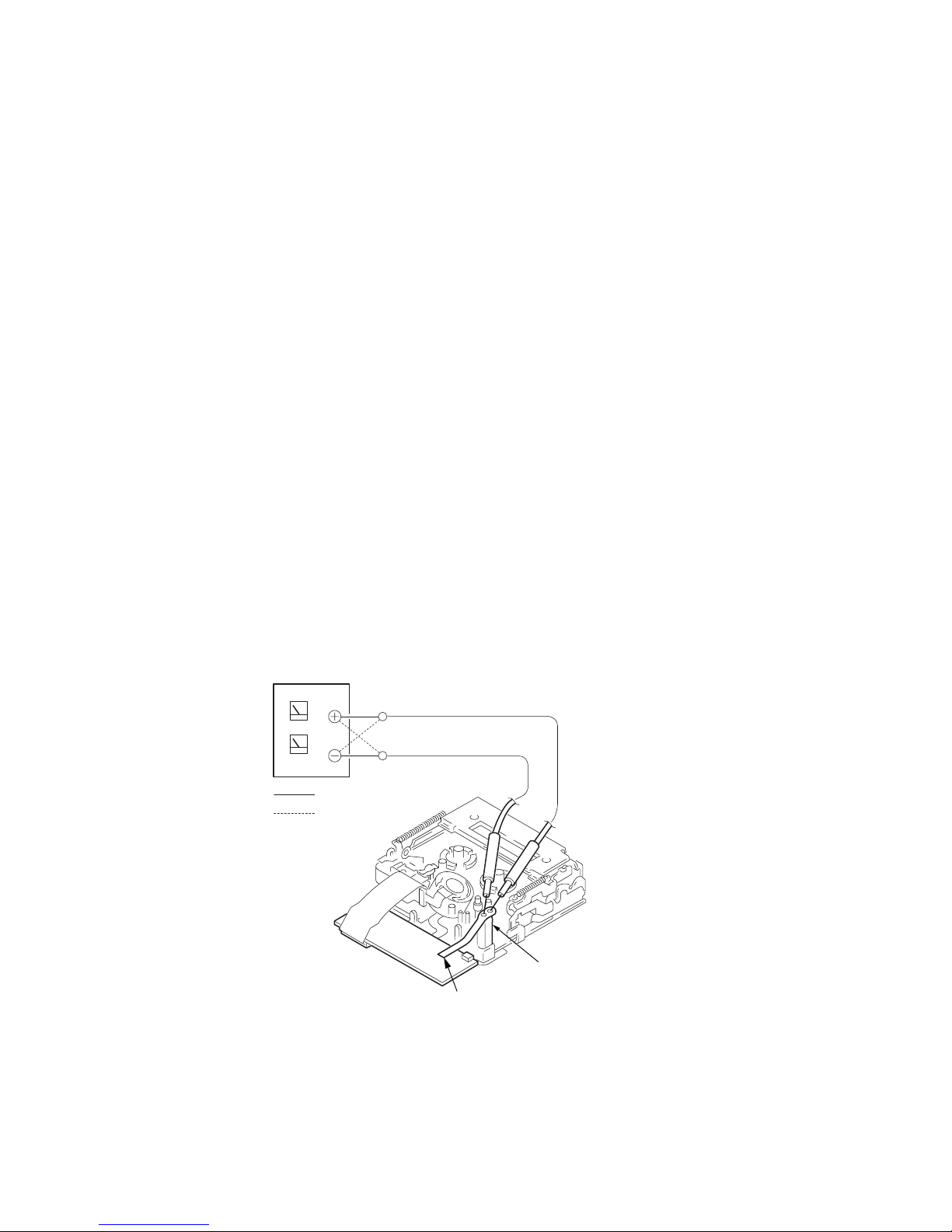
2. TO TAKE OUT A CASSETTE WHEN
NOT EJECT (FORCE EJECT)
1 Refer to 2-2 to remove the accessory shoe and NS block
assembly.
2 Refer to 2-2 to remove the jack ornamental plate.
3 Refer to 2-2 to remove the tripod screw.
4 Refer to 2-2 and 2-3 to remove the cabinet (R) block assembly .
5 Refer to 2-5 to remove the microphone unit.
6 Refer to 2-5 to remove the battery plate.
7 Refer to 2-5 to remove DD-125 board.
8 Refer to 2-5 to remove EVF and lens block.
9 Refer to 2-6 to remove the cabinet (L) block assembly.
0 Open MR-41 board.
!¡ Disconnect CN2504 (4P, 0.8mm) of MR-41 board.
!™ Add +4.5V from the DC POWER SUPPLY and unload with a
pressing the cassette compartment.
SERVICE NOTE
: Unloading
: Loading
Loading motor
Disconnect from CN2504 of MR-41 board.
MR-41
BOARD
— 5 —
SELF-DIAGNOSIS FUNCTION
1. SELF-DIAGNOSIS FUNCTION
When problems occur while the unit is operating, the self-diagnosis
function starts working, and displays on the viewfinder or LCD
screen what to do.
Details of the self-diagnosis functions are provided in the Instruction
manual.
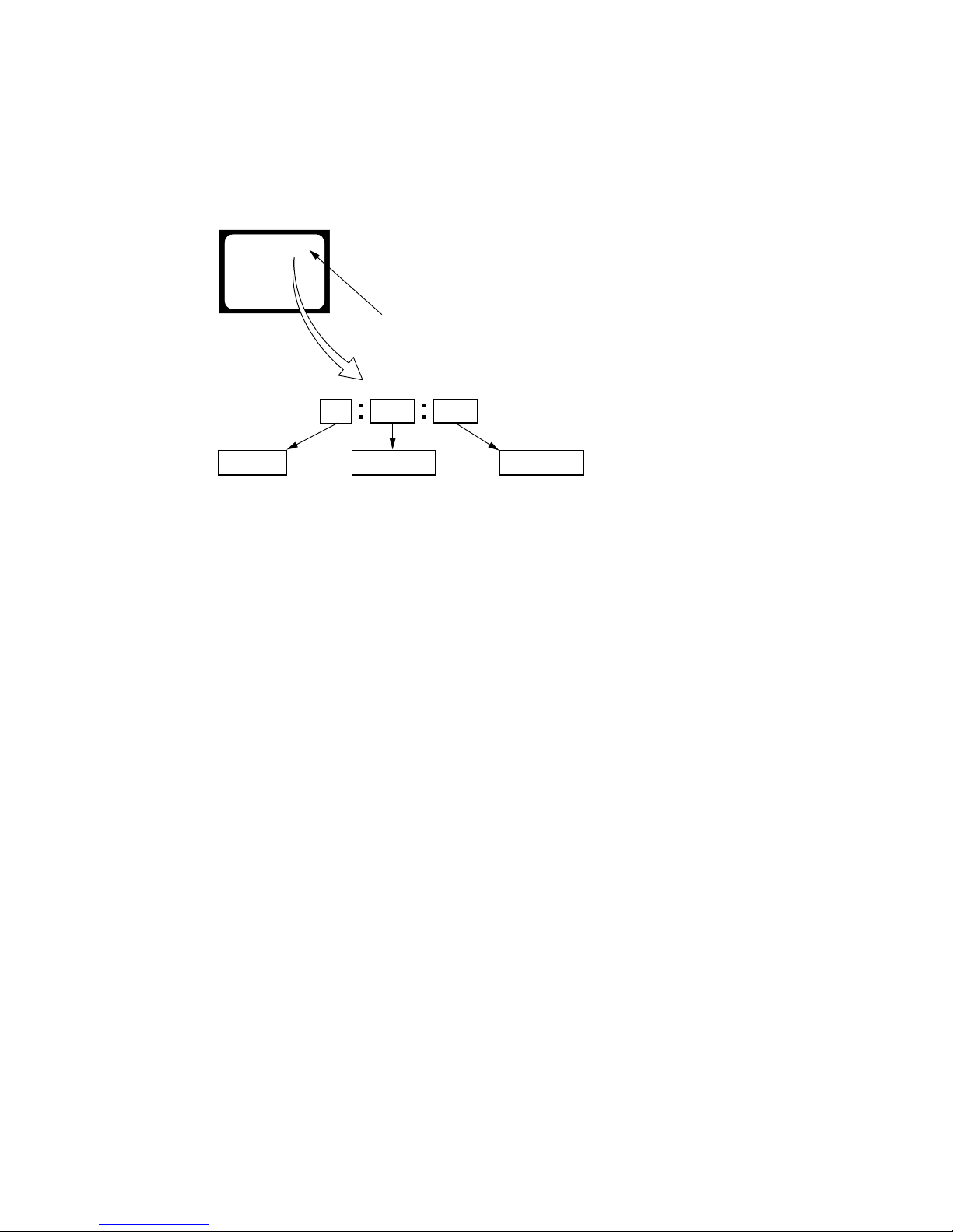
2. SELF-DIAGNOSIS DISPLAY
When problems occur while the unit is operating, the counter of the
viewfinder or LCD screen consists of an alphabet and 4-digit
numbers, which blinks at 3.2 Hz. This 5-character display indicates
the “repaired by:”, “block” in which the problem occurred, and
“detailed code” of the problem.
1 1
3 1C
Repaired by:
Refer to page 6.
Self-diagnosis Code Table.
Indicates the appropriate
step to be taken.
E.g.
31 ....Reload the tape.
32 ....T u r n o n power again.
Block
Detailed Code
Blinks at 3.2Hz
C : Corrected by customer
H : Corrected by dealer
E : Corrected by service
engineer
Viewfinder or LCD screen
C : 3 1 : 1 1

— 6 —
3. SELF-DIAGNOSIS CODE TABLE
C
C
C
C
C
C
C
C
C
C
C
C
C
C
C
C
C
C
C
C
C
C
C
E
E
E
E
Block
Function
23
21
22
31
31
31
31
31
31
31
31
31
31
31
31
32
32
32
32
32
32
32
32
61
61
62
62
Detailed
Code
00
00
00
10
11
20
21
22
23
24
30
40
42
10
11
20
21
22
23
24
30
40
42
00
10
00
01
Symptom/State
Non-standard battery is used.
Condensation.
Video head is dirty.
LOAD direction. Loading does not
complete within specified time
UNLOAD direction. Loading does not
complete within specified time
T reel side tape slacking when unloading
.
Winding S reel fault when counting the
rest of tape.
T reel fault.
S reel fault.
T reel fault.
FG fault when starting capstan.
FG fault when starting drum.
FG fault during normal drum operations.
LOAD direction loading motor time-
out.
UNLOAD direction loading motor
time-out.
T reel side tape slacking when
unloading.
Winding S reel fault when counting the
rest of tape.
T reel fault.
S reel fault.
T reel fault.
FG fault when starting capstan.
FG fault when starting drum
FG fault during normal drum
operations
Difficult to adjust focus
(Cannot initialize focus.)
Zoom operations fault
(Cannot initialize zoom lens.)
Steadyshot function does not work well.
(With pitch angular velocity sensor output
stopped.)
Steadyshot function does not work well.
(With yaw angular velocity sensor output
stopped.)
Self-diagnosis Code
Repaired by:
Correction
Use the info LITHIUM battery.
Remove the cassette, and insert it again after one hour.
Clean with the optional cleaning cassette.
Load the tape again, and perform operations from the beginning.
Load the tape again, and perform operations from the beginning.
Load the tape again, and perform operations from the beginning.
Load the tape again, and perform operations from the beginning.
Load the tape again, and perform operations from the beginning.
Load the tape again, and perform operations from the beginning.
Load the tape again, and perform operations from the beginning.
Load the tape again, and perform operations from the beginning.
Load the tape again, and perform operations from the beginning.
Load the tape again, and perform operations from the beginning.
Remove the battery or power cable, connect, and perform
operations from the beginning.
Remove the battery or power cable, connect, and perform
operations from the beginning.
Remove the battery or power cable, connect, and perform
operations from the beginning.
Remove the battery or power cable, connect, and perform
operations from the beginning.
Remove the battery or power cable, connect, and perform
operations from the beginning.
Remove the battery or power cable, connect, and perform
operations from the beginning.
Remove the battery or power cable, connect, and perform
operations from the beginning.
Remove the battery or power cable, connect, and perform
operations from the beginning.
Remove the battery or power cable, connect, and perform
operations from the beginning.
Remove the battery or power cable, connect, and perform
operations from the beginning.
Inspect the lens block focus reset sensor (Pin 7 of CN201 of VC-
220 board) when focusing is performed when the control dial is
rotated in the focus manual mode, and the focus motor drive circuit
(IC503 of VC-220 board) when the focusing is not performed.
Inspect the lens block zoom reset sensor (Pin @º of CN201 of VC220 board) when zooming is performed when the zoom lens is
operated and the zoom motor drive circuit (IC503 of VC-220 board)
when zooming is not performed.
Inspect pitch angular velocity sensor (SE2501 of MR-41 board)
peripheral circuits.
Inspect yaw angular velocity sensor (SE2500 of MR-41 board)
peripheral circuits.
— 7 —
1. MAIN PARTS
Note:
• Follow the disassembly procedure in the numerical order given.
• Items marked “*” are not stocked since they are seldom required for routine service.
Some delay should be anticipated when ordering these items.
• The parts numbers of such as a cabinet are also appeared in this section.
Refer to the parts number mentioned below the name of parts to order.
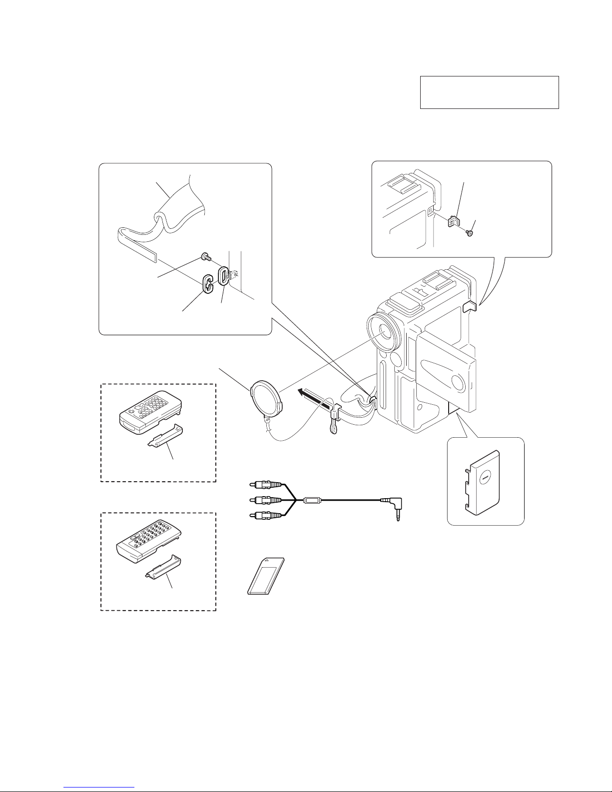
1. ORNAMENTAL PARTS
DCR-PC2E/PC3E
The components identified by mark ! or
dotted line with mark ! are critical for safety .
Replace only with part number specified.
Grip belt
Bracket cap
3-978-785-01
Battery terminal cover
3-052-290-11
LCD lock base
3-055-819-01
Screw (M2
×
3)
3-724-455-41
Screw (M2 × 3)
3-724-455-41
Strap bracket
3-978-784-01
Lens cap assembly
X-3949-687-1
Battery case lid (for RMT-812)
3-053-056-01 (PC3E)
Remote commander (RMT-812)
1-475-950-31 (PC3E)
Battery case lid (for RMT-809)
3-742-852-21 (PC2E)
Remote commander (RMT-809)
1-475-141-31 (PC2E)
A/V connecting cable (1.5m)
1-777-433-21
Memory Stick (MSA-4A)
A-7033-233-A
(DCR-PC3E only)
— 8 —
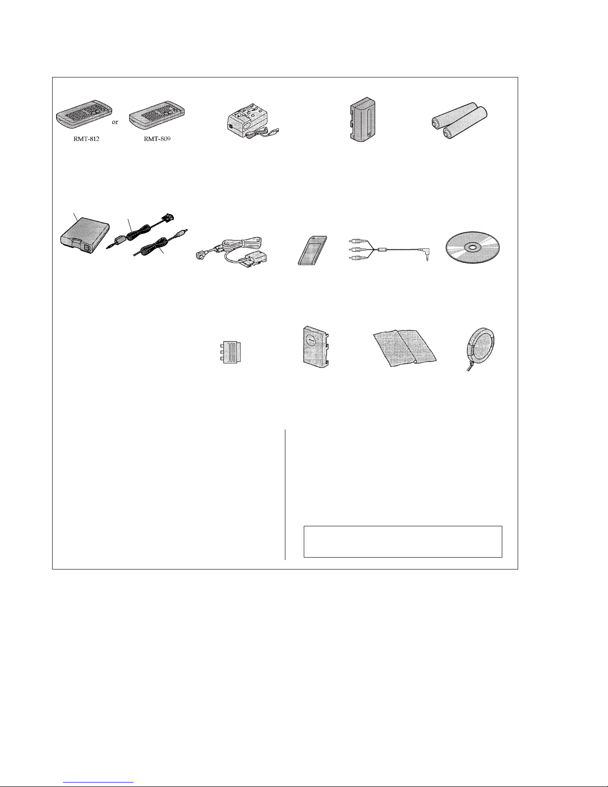
Checking supplied accessories.
Check that the following accessories are supplied with your camcorder.
Wireless Remote Commander (1)
RMT-809 (DCR-PC2E only)
1-475-141-31
RMT-812 (DCR-PC3E only)
1-475-950-31
AC-VF10 power adaptor (1)
!
1-475-851-33
Power cord set (1)
(DCR-PC2E: AEP, DCR-PC3E: AEP only)
!
1-690-827-11
Power cord (with filter) (1)
(DCR-PC2E: UK, DCR-PC3E: UK only)
!
1-775-843-21
NP-FS11
battery pack (1)
Size AA (R6) battery for
Remote Commander (2)
(not supplied)
A/V connecting
cable (1.5m) (1)
1-777-433-21
21-pin adaptor (1)
1-573-291-11
Lens cap (1)
X-3949-687-1
Cleaning cloth (1)
3-967-386-01
Other accessories
3-866-544-11 MANUAL, INSTRUCTION (PICTURE GEAR)
(ENGLISH,RUSSIAN) (PC3E)
3-866-544-21 MANUAL, INSTRUCTION (PICTURE GEAR)
(GERMAN,FRENCH) (PC3E:AEP)
3-866-544-31 MANUAL, INSTRUCTION (PICTURE GEAR)
(ITALIAN,DUTCH) (PC3E:AEP)
3-866-544-41 MANUAL, INSTRUCTION (PICTURE GEAR)
(SPANISH,PORTUGUESE) (PC3E:AEP)
3-866-727-11 MANUAL, INSTRUCTION (MSAC-SR1)
(ENGLISH,RUSSIAN) (PC3E)
3-866-727-21 MANUAL, INSTRUCTION (MSAC-SR1)
(GERMAN,FRENCH) (PC3E:AEP)
3-866-727-31 MANUAL, INSTRUCTION (MSAC-SR1)
(ITALIAN,DUTCH) (PC3E:AEP)
Application software:
Picture Gear 3.2Lite
(CD ROM) (1)
1-772-118-12
DK-115
Connecting cord (1)
1-783-739-13
Fig A
PC serial cable (1) (DCR-PC3E only)
1-790-774-11
Fig B
Serial port adaptor for Memory Stick
(MSAC-SR1) (1) (DCR-PC3E only)
A-7094-296-A
Fig C
AC power adaptor for Serial port adaptor
(AC-PT1) (1) (DCR-PC3E: AEP only)
!
1-467-511-72
(AC-PT1) (1) (DCR-PC3E: UK only)
!
1-467-512-42
Memory Stick (1)
(DCR-PC3E only)
A-7033-233-A
Battery terminal cover (1)
3-052-290-11
3-866-727-41 MANUAL, INSTRUCTION (MSAC-SR1)
(SPANISH,PORTUGUESE) (PC3E:AEP)
3-866-966-11 MANUAL, INSTRUCTION (ENGLISH,RUSSIAN)
3-866-966-21 MANUAL, INSTRUCTION (SPANISH,PORTUGUESE)
(PC2E:AEP/PC3E:AEP)
3-866-966-31 MANUAL, INSTRUCTION (DUTCH,FRENCH)
(PC2E:AEP/PC3E:AEP)
3-866-966-41 MANUAL, INSTRUCTION (GERMAN,ITALIAN)
(PC2E:AEP/PC3E:AEP)
Note : The components identified by mark ! or dotted
line with mark ! are critical for safety.
Replace only with part number specified.
Fig B
Fig A
Fig C

— 9 —
2. DISASSEMBLY
The following flow chart shows the disassembly procedure.
DCR-PC2E/PC3E
2-1. LCD unit
(PD-112 board, Inverter transformer unit)
2-2. Cabinet (R) block assembly
2-10. EVF, Lens block
2-9. Cabinet (L) assembly
2-3. Cabinet (R) assembly,
LCD hinge assembly
2-4. Attaching harnesses of the LCD
hinge assembly
2-5. DD-125, VC-220 boards,
EVF block assembly
2-6. MR-41 board, MD block
2-7. Control switch block (FK-4750),
Speaker (2.0 cm)
2-8. Cabinet (G) assembly
— 10 —
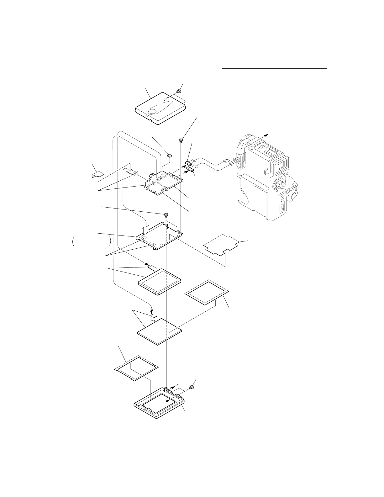
2-1. LCD UNIT (PD-112 BOARD, INVERTER TRANSFORMER UNIT)
NOTE: Follo w the disassembly procedure in the numerical order given.
NOTE:
• Items marked “*” are not stocked since they are
seldom required for routine service. Some delay
should be anticipated when ordering these items.
PD
-112
Board
A
A
B
B
3
PD spacer
!£
LCD unit (24P)
!∞
Two claws
!§
BL shield sheet
!¶
Remove the
three solderings
4
BL insulating sheet
!•
Back light
Cold cathode
fluorescent tube
!ª
Inverter
transformer unit
1
Two screws (M1.7 × 2.5),
lock ace, p2
2
LCD cabinet (R) assembly
3-989-735-11
!¢
Screw (M1.7 × 2.5),
lock ace, p2
3-989-735-11
8
Two screws
(M1.7
×
2.5),
lock ace, p2
3-989-735-11
3-055-797-01
9
Panel protection
sheet
3-055-839-01
3-055-802-01
5
Two screws (M1.7 × 2.5),
lock ace, p2
3-989-735-11
X-3949-692-1
X-3949-728-1 (PC2E)
X-3949-720-1 (PC3E)
3-056-504-01
1-959-831-11
1-959-832-11
3-055-798-01
6
PT-124 harness
(13P)
!ª
PD-112 board
7
TP-112 harness
(8P)
!º
LCD cabinet (L)
assembly
!¡
Panel spacer
!™
Touch panel
(TP-4750) (5P)
— 11 —
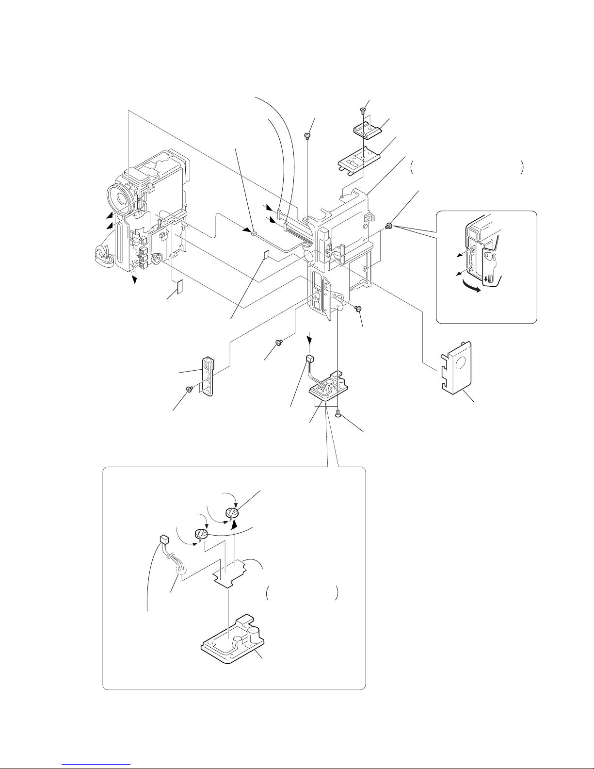
2-2. CABINET (R) BLOCK ASSEMBLY
VC-220
Board
C
C
A
B
7
FP-36 flexible board
Attached with tripod
screw.
2
Two screws (+K M2 × 3.5)
5
Two screws (+K M2 × 3.5)
3
Accessory shoe
4
NS block assembly
8
Screw (M1.7 × 2.5),
lock ace, p2
!™
Screw
(M1.7 × 2.5),
lock ace, p2
!£
Push the eject knob in
the direction of the arrow,
and open the cassette lid.
!¡
Screw
(M1.7 × 2.5),
lock ace, p2
6
LI-58 harness (2P)
7
8
Tripod screw
2
Lithium
secondary
battery
4
Lithium
secondary
battery
1
Battery terminal
cover
!¢
Two screws (M1.7 × 2.5),
lock ace, p2
9
T wo screws
(M1.7 × 2.5),
lock ace, p2
!º
Jack ornamental plate
@º
Cabinet (R) block assembly
When removing it, be careful not
to damage the harnesses, etc.
1
Remove the
two solderings
3
Remove the
two solderings
5
Remove the
two solderings
REMOVING THE LITHIUM SECONDARY BATTERY
A
B
!§
PT-124 harness (13P)
!∞
TP-112 harness (10P)
!•
TP-112 harness (2P)
!¶
Spacer (C)
!ª
Lens flexible sheet (2)
3-052-290-11
3-056-624-01
3-056-624-01
*
1-528-909-11
*
1-528-909-11
1-670-867-11
3-056-315-01
1-959-018-11
6
LI-58 harness
1-959-018-11
3-724-511-51
X-3949-723-1
3-989-735-11
1-959-831-11
1-959-832-11
1-959-832-11
3-989-735-11
3-989-735-11
*
3-056-806-01
3-989-735-11
3-989-735-11
3-055-790-21
*
3-846-067-21
— 12 —
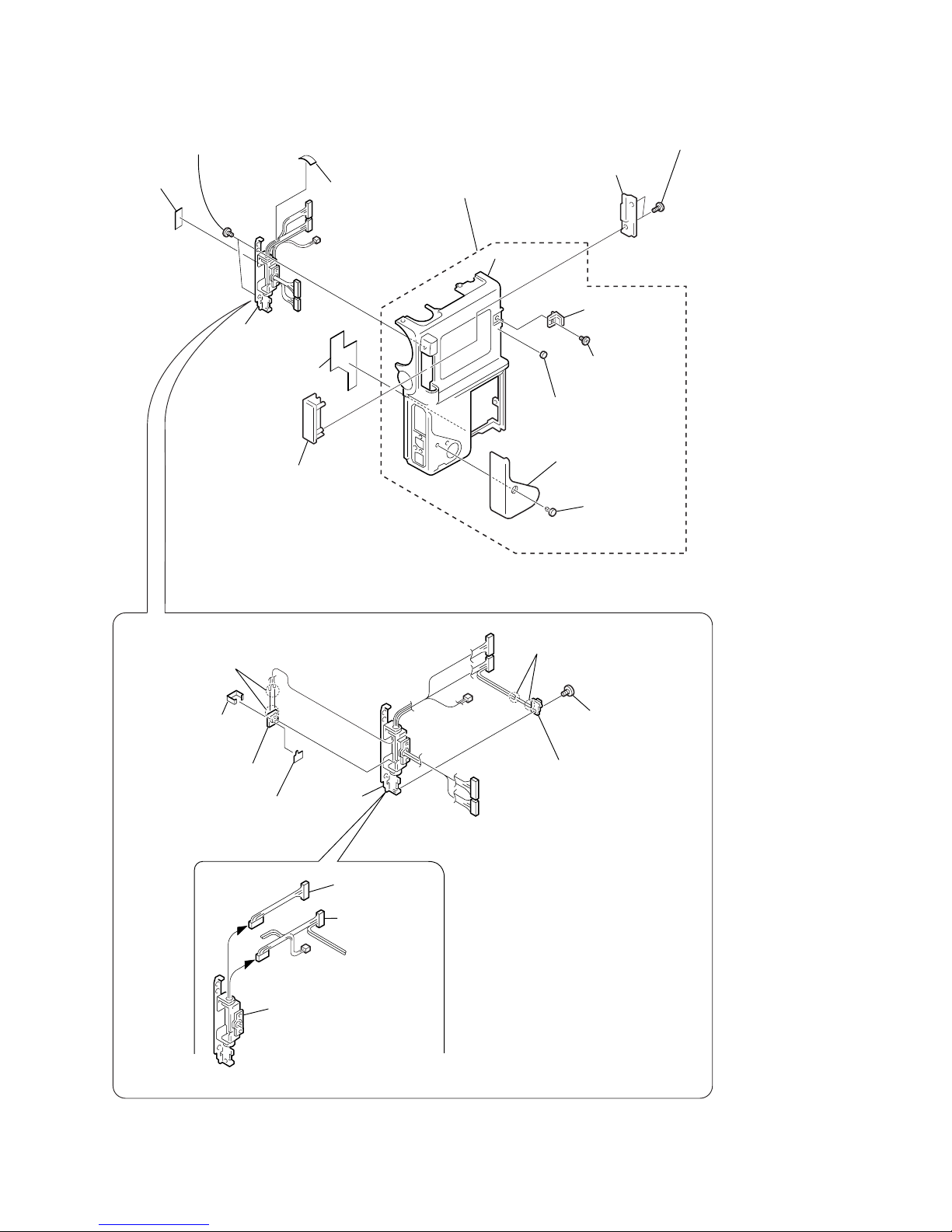
2-3. CABINET (R) ASSEMBLY, LCD HINGE ASSEMBLY
8
4
Hinge cover (rear)
5
Hinge cover (front)
3
Two tapping screws
(M1.7
×
5)
1
DD protection sheet
9
Cabinet (R) assembly
!º
Lock spacer
!™
LCD lock base
!£
DV S cover pin
!¢
DV S terminal cover
6
T wo screws
(M1.7
×
2.5),
lock ace, p2
8
1
Screw (M1.7 × 2.5),
lock ace, p2
2
Remove the
two solderings
6
Remove the
two solderings
4
SW clip
3
PO-4 board
7
PR-32 board
5
PR insulating sheet
!º
PT-124 harness
9
TP-112 harness
!¡
LCD hinge assembly
!∞
not supplied
3-056-318-01
2
Spacer (C)
*
3-846-067-21
7
Spacer (C)
*
3-846-067-21
*
3-055-801-01
3-713-791-11
3-055-800-01
3-052-283-01
3-055-823-01
3-055-824-01
*
3-057-035-01
3-724-455-41
3-055-819-01
X-3949-724-1
3-055-799-01
3-989-735-11
3-989-735-11
!¡
Screw (M2)
REMOVING THE LCD HINGE ASSEMBLY
1-959-832-11
X-3949-690-1
1-959-831-11
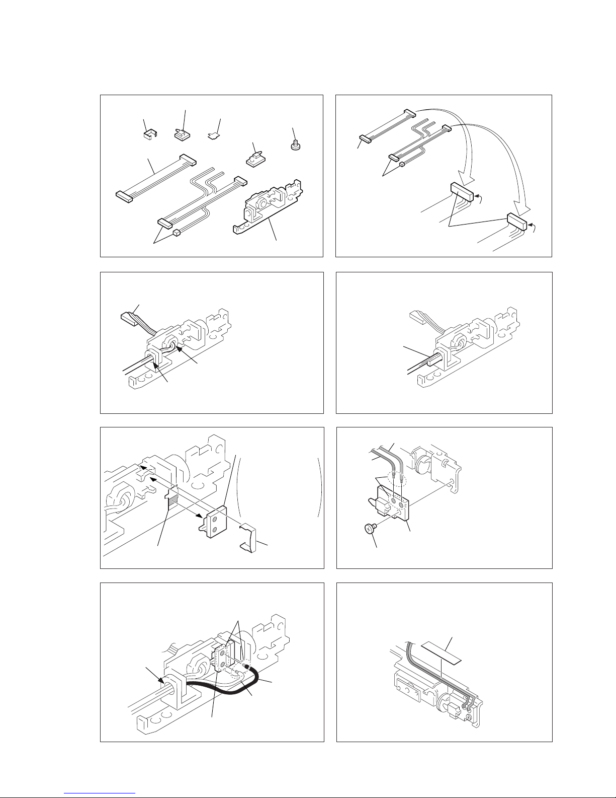
— 13 —
12
34
5
7
6
A
B
A
8
SW clip
PR-32 board PR insulating
sheet
1
PR insulating sheet
Screw
(M1.7
×
2.5),
lock ace, p2
2
Screw (M1.7 × 2.5),
lock ace, p2
PO-4 board
1
PO-4 board
PR-32 board
White
Black
3
Solder
here.
Solder here.
PT-124 harness
TP-112 harness
LCD hinge assembly
Then bend the harness so that
it is laid along with the connector.
Route the LCD harness
(TP-112) through the hole
A
toward the center, then route
it through the center hole
B
.
Route the harness.
Gray
Adhere the gray and black wires (TP-112 harness)
as shown with adhesive tape (HIMERON).
Tape (HIMERON)
Attach the PO-4 board
with screw (M1.7
×
2.5).
Solder the gray and
black wires (TP-112
harness) to the positions
as shown.
Red
(Attach it on SW.)
Attach the PR-32
board with SW clip.
Place the PR-32
board in the direction
that the solder-escape
is directed to
soldering.
PT-124
harness
TP-112
harness
Bend one of the two
harnesses at its connector.
(13P)
(8P)
2
PR-32 board
3
SW clip
Route the red and white wires (TP-112 harness) through
the hole
A
as shown and solder them to the PR-32 board.
2-4. ATTACHING HARNESSES OF THE LCD HINGE ASSEMBLY
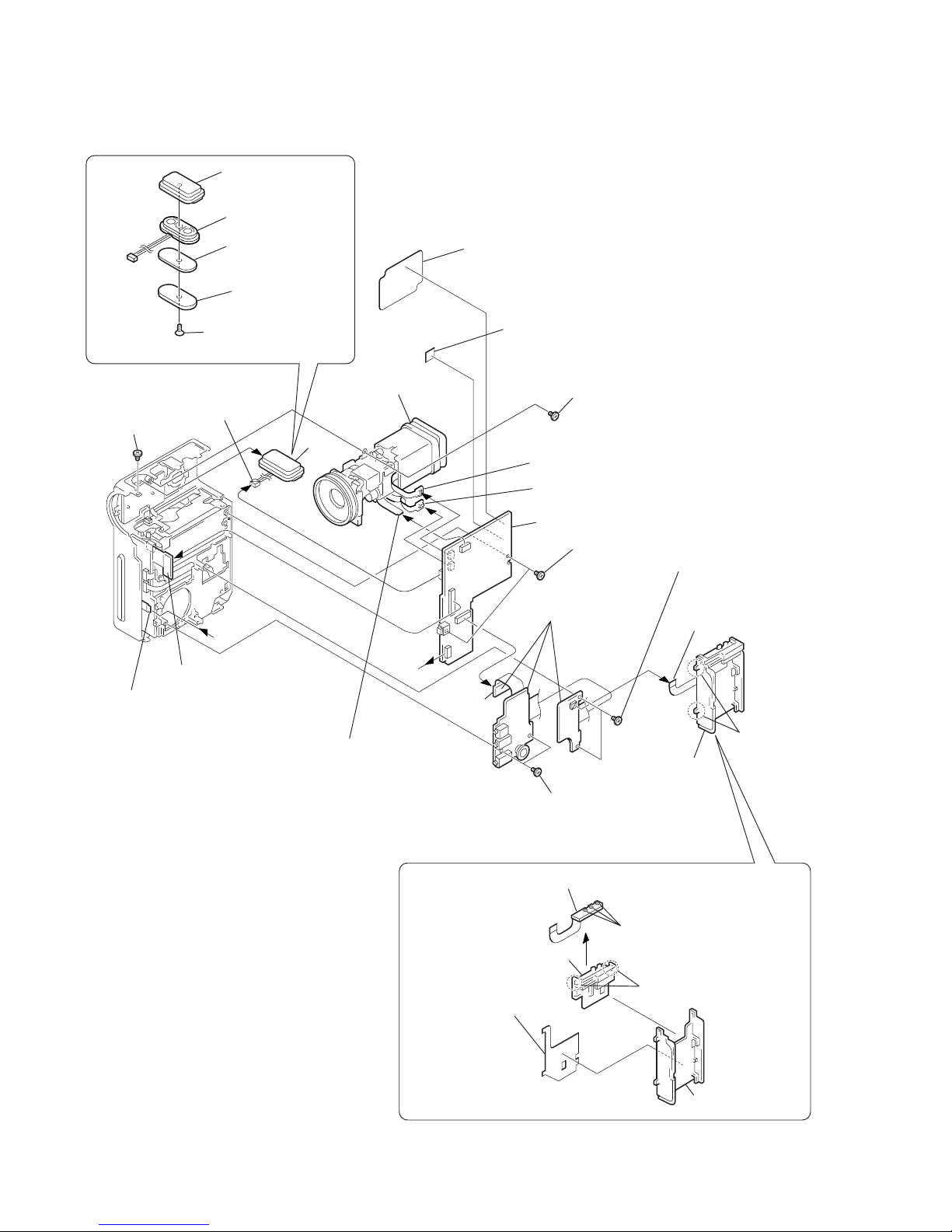
— 14 —
2-5. DD-125, VC-220 BOARDS, EVF BLOCK ASSEMBLY
DD-125
Board
DD-125
VC-220
Board
A
A
*
3-052-248-01
4
Microphone
case assembly
!¢
5
Microphone unit
!£
Microphone unit
(4P)
3
Microphone gel
sheet
2
Microphone
retainer plate
2
Two claws
3
2
Two claws
3
Battery plate
1
Battery plate sheet
*
3-055-789-01
*
3-051-227-01
*
3-051-990-01
!∞
VC sheet
3-057-190-01
!§
VC spacer
1
TB-38 board (20P)
1
Tapping screw (+K B2)
5
TB-38 board
6
Battery terminal board
REMOVING THE MICROPHONE UNIT
REMOVING THE TB-38 BOARD
4
Remove the three solderings
5
Two screws (M1.7 × 2.5),
lock ace, p2
!ª
Screw (M1.7 × 2.5),
lock ace, p2
!•
Screw
(M1.7
×
2.5),
lock ace, p2
6
DD-125 board
(60P)
!¶
VC-220 board
8
MR-41 board (100P)
9
Control switch block (FK-4750) (27P)
!™
CD-221 board (20P)
!¡
VF-136 board (20P)
@º
EVF block assembly
7
Flexible board
(from lens block)(27P)
!º
Two screws (M1.7 × 2.5),
lock ace, p2
4
T wo screws
(M1.7
×
2.5),
lock ace, p2
3-989-735-11
3-989-735-11
1-694-459-11
3-989-735-11
3-989-735-11
3-989-735-11
3-736-363-31
1-475-975-11
1-475-975-11
X-3949-685-1
1-418-497-21 (PC2E)
1-418-497-11 (PC3E)
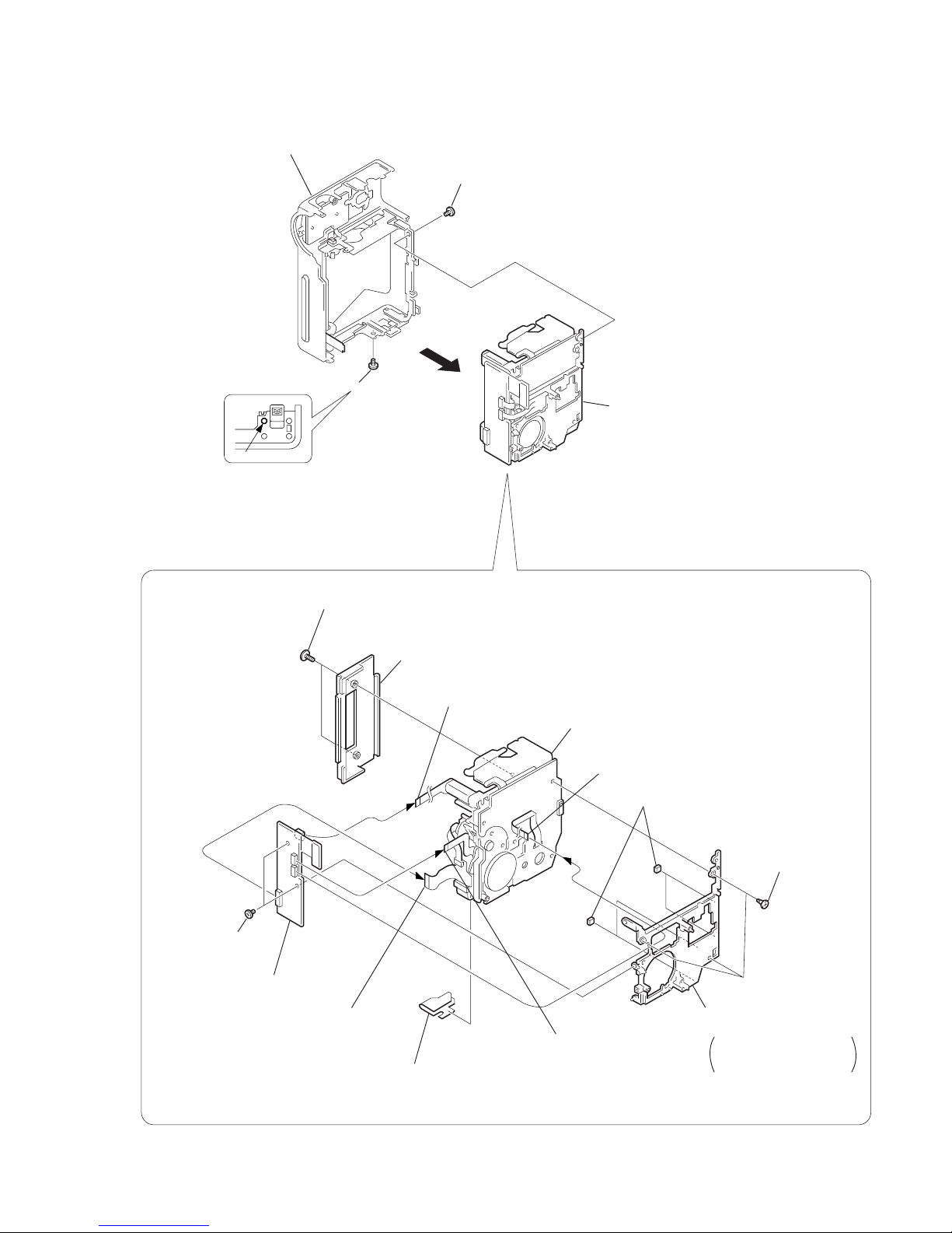
— 15 —
2-6. MR-41 BOARD, MD BLOCK
M
R
-41
MR-41
4
1
Screw
(M1.7
×
2.5),
lock ace, p2
2
Screw
(M1.7 × 2.5),
lock ace, p2
3
Cabinet (L) block assembly
3-989-735-11
3-989-735-11
3-964-734-01
3-055-785-01
3-975-921-01
3-719-695-21
X-3947-927-1
3-055-788-01
3-989-735-11
The cabinet (L)
when viewed
from the bottom
2
Two special head screws
(M1.7 × 3.5)
1
Cap flexible sheet
3
Cassette compartment
cover assembly
4
Flexible board
(from drum motor)(10P)
5
FP-91 flexible board (6P)
6
FP-92 flexible board (51P)
7
Two screws
(M1.7
×
2.5),
lock ace, p2
8
FP-586 flexible board (4P)
9
MR-41 board
!º
Three step
screws
Be careful that the FP-91
flexible board must not be
caught when removing it.
!™
MD frame
!¡
Vibration proof sheet
!£
MD block
REMOVING THE MD BLOCK
— 16 —
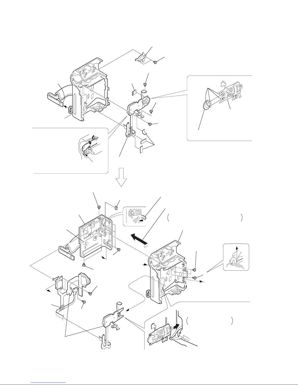
2-7. CONTROL SWITCH BLOCK (FK-4750), SPEAKER (2.0 CM)
D
C
C
D
A
B
1
Two screws (M1.7 × 2.5), lock ace, p2
3
Screw
(M1.7
×
2.5),
lock ace, p2
9
SP cushion
3-831-441-11
4
Screw
(M1.7 × 2.5),
lock ace, p2
7
Screw
(M1.7
×
2.5),
lock ace, p2
1
Three screws
(M1.7 × 2.5)
4
Two screws
(M1.7 × 2.5)
3
Two screws
(M1.7
×
2.5)
!£
Two tapping
screws
(M1.7
×
5)
!™
Tapping
screw
(M1.7
×
4)
5
Tapping screw (M1.7 × 5)
2
Screw (M1.7 × 2.5)
!º
Jack fixed plate
!¡
Open the HP jack cover.
7
Remove the cabinet (G) assembly from the
cabinet (L) block assembly in the arrow direction.
Be careful not to damage the control switch
block's (FK-4750) flexible.
8
Remove the control switch block
that is attached to the cabinet (R),
from the cabinet (R).
Be careful that the flexible
must not be caught.
Be careful that the flexible
must not be caught.
!∞
Cabinet (G) assembly
!™
Remove an end of
the grip belt from
the strap bracket
5
Three spacer (C)
6
Peel off the area
shown by shading.
!¢
Peel off the
area shown
by shading.
6
Claw
8
Slant the block in the
direction of the arrow A,
then remove the block
in the direction of the
arrow
B
.
2
SP retainer plate
!º
Remove the
two solderings
!¡
Speaker (2.0 CM)
Control switch block
(FK-4750)
!§
Control switch block (FK-4750)
3-989-735-11
3-989-735-11
1-418-497-21 (PC2E)
1-418-497-11 (PC3E)
1-418-497-21 (PC2E)
1-418-497-11 (PC3E)
X-3949-730-1 (PC2E)
X-3949-726-1 (PC3E)
9
Cabinet (L) assembly
X-3949-729-1 (PC2E)
X-3949-725-1 (PC3E)
3-989-735-11
3-989-735-11
3-057-082-01
3-057-082-01
3-713-791-11
3-057-082-01
3-055-860-01
3-713-791-71
3-713-791-11
3-055-804-01
3-057-082-01
1-505-862-11
*
3-055-805-01
*
3-846-067-21
REMOVING
THE SPEAKER (2.0 CM)
— 17 —
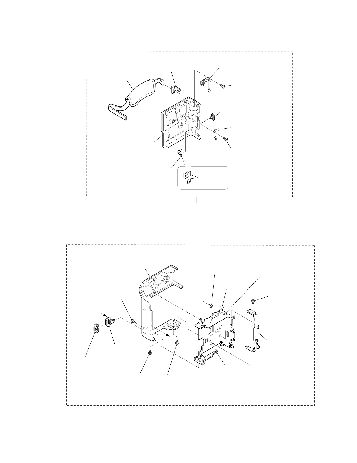
2-9. CABINET (L) ASSEMBLY
2-8. CABINET (G) ASSEMBLY
!º
not supplied
1
Two claws
2
G lock slider
3
Eject knob
3-051-177-11
4
Tapping screw (M1.7 × 5)
3-713-791-11
3-978-765-01
8
Tapping screw (M1.7 × 5)
3-713-791-11
9
MS door assembly
X-3949-697-1
5
Belt bracket
*
3-055-848-01
6
Grip belt
3-051-187-01
7
HP jack cover
3-055-860-01
Cabinet (G) assembly
X-3949-730-1 (PC2E)
X-3949-726-1 (PC3E)
D
D
!™
not supplied
2
Strap bracket
1
Screw (M2)
*
3-978-784-01
3
Bracket cap
*
3-978-785-01
3-724-455-41
4
Two screws (M1.7 × 2.5),
lock ace, p2
3-989-735-11
5
Screw (M1.7 × 2.5),
lock ace, p2
3-989-735-11
6
Lock plate
3-051-171-01
!¡
Grip lock assembly
X-3949-696-1
7
T wo screws
(M1.7
×
2.5),
lock ace, p2
3-989-735-11
8
Screw
9
claw
!º
claw
3-051-390-21
Cabinet (L) assembly
X-3949-729-1 (PC2E)
X-3949-725-1 (PC3E)
 Loading...