

Page 1
4-111-559-01(2)
FWD-S42H1/FWD-S47H1
Flat Wide
Display Monitor
取扱説明書
Operating Instructions
Mode d’emploi
Bedienungsanleitung
Manual de instrucciones
Istruzioni per l’uso
JP
GB
FR
DE
ES
IT
CS
Sony Corporation Printed in Korea
お買い上げいただきありがとうございます。
電気製品は安全のための注意事項を守らないと、
火災や人身事故になることがあります。
この取扱説明書には、事故を防ぐための重要な注意事項と製品の取
り扱いかたを示してあります。この取扱説明書をよくお読みのうえ、
製品を安全にお使いください。お読みになったあとは、いつでも見
られるところに必ず保管してください。
FWD-S42H1/FWD-S47H1
© 2008 Sony Corporation
Page 2
安全のために
ソニー製品は安全に充分配慮して設計されています。しかし、電気
製品は、まちがった使いかたをすると、火災や感電などにより死亡
や大けがなど人身事故につながることがあり、危険です。
事故を防ぐために次のことを必ずお守りください。
安全のための注意事項を守る
4 〜 8 ページの注意事項をよくお読みください。
9 ページの「本機の性能を保持するために」もあわせてお読みくだ
さい。
定期点検をする
長期間安全に使用していただくために、定期点検を実施することを
おすすめします(有料)。点検の内容や費用については、ソニーの
サービス窓口にご相談ください。
故障したら使わない
すぐに、お買い上げ店またはソニーのサービス窓口にご連絡くださ
い。
万一、異常が起きたら
・ 煙が出たら
・ 異常な音、におい
がしたら
・ 内部に水、異物が
入ったら
・ 製品を落としたり
キャビネットを破
損したときは
1 ディスプレイの電源を切る。
2 ディスプレイの電源コードや
,
接続コードを抜く。
3 お買い上げ店またはソニーの
サービス窓口に連絡する。
警告表示の意味
取扱説明書および製品で
は、次のような表示をして
います。表示の内容をよく
理解してから本文をお読み
ください。
この表示の注意事項を守ら
ないと、火災や感電などに
より死亡や大けがなど人身
事故につながることがあり
ます。
この表示の注意事項を守ら
ないと、感電やその他の事
故によりけがをしたり周辺
の物品に損害を与えたりす
ることがあります。
注意を促す記号
行為を禁止する記号
この装置は、情報処理装置等電波障害自主規制協議会(VCCI)の基準
に基づくクラス B 情報技術装置です。この装置は、家庭環境で使用す
ることを目的としていますが、この装置がラジオやテレビジョン受信
機に近接して使用されると、受信障害を引き起こすことがあります。
取扱説明書に従って正しい取り扱いをしてください。
JP
2
行為を指示する記号
Page 3

目次
警告 .................................................................................................................................................... 4
注意 .................................................................................................................................................... 5
電池についての安全上のご注意...................................................................................................... 7
その他の安全上のご注意..................................................................................................................8
使用上のご注意(性能を保持するために).....................................................................................9
設置するときのご注意 ..................................................................................................................10
各部の名称と働き
前面 ................................................................................................................................................. 11
後面 ................................................................................................................................................. 12
リモコン.......................................................................................................................................... 15
ボタンの機能 ............................................................................................................................15
リモコンの特別ボタン ............................................................................................................. 17
ワイド切換を使う ............................................................................................................... 17
2 画面設定を使う ............................................................................................................... 18
IDMODE ボタンを使う .................................................................................................... 19
オプションアダプター ..................................................................................................................20
接続
JP
スピーカーの接続 .......................................................................................................................... 21
電源コードの接続 .......................................................................................................................... 21
ケーブルを処理する ......................................................................................................................22
メニューの設定
メニュー一覧.................................................................................................................................. 23
画質 / 音質メニュー ......................................................................................................................24
画面メニュー.................................................................................................................................. 28
設定メニュー.................................................................................................................................. 32
ネットワーク機能
ネットワーク機能を使う準備をする ...........................................................................................35
PC で操作する ............................................................................................................................... 37
その他の情報
故障かな?と思ったら ..................................................................................................................40
入力信号一覧表 .............................................................................................................................. 42
仕様 ................................................................................................................................................. 44
索引 ................................................................................................................................................. 46
JP
3
Page 4
警告
下記の注意を守らないと、 火災や感
により死亡や大けがにつながる
電
ことがあります。
規定の電源電圧で使う
この取扱説明書に記されている
電源電圧でお使いください。
規定外の電源電圧での使用は、
火災や感電の原因となります。
油煙、湯気、湿気、ほこりの多い場
所では設置・使用しない
上記のような場所に設置すると、
火災や感電の原因となります。
この取扱説明書に記されている
仕様条件以外の環境での使用は、
火災や感電の原因となります。
分解や改造をしない
分解や改造をすると、火災や感
電、けがの原因となることがあ
ります。
内部の点検や修理は、お買い上
げ店またはソニーのサービス窓
口にご依頼ください。
電源コードを傷つけない
電源コードを傷つけると、火災
や感電の原因となります。次の
項目を必ずお守りください。
・ 設置時に、製品と壁やラック、
棚などの間に、はさみ込まな
い。
・ 電源コードを加工したり、傷
つけたりしない。
・ 重いものをのせたり、引っ
張ったりしない。
・ 熱器具に近づけたり、加熱し
たりしない。
・ 電源コードを抜くときは、必
ずプラグを持って抜く。
万一、電源コードが傷んだら、
お買い上げ店またはソニーの
サービス窓口に交換をご依頼く
ださい。
内部に水や異物をいれない
水や異物が入ると火災や感電の
原因となることがあります。
万一、水や異物が入ったときは、
すぐに電源を切り、電源コード
や接続コードを抜いて、お買い
上げ店またはソニーのサービス
窓口にご相談ください。
設置・取り付けは確実に
不確実な設置を行うと、ディス
プレイが転倒してけがや火災・
感電の原因となります。設置の
際は、以下の注意事項を必ずお
守りください。
壁面・天井・台上への設置、ま
たは転倒防止のためディスプレ
イを固定するなど、特殊な設置
を行う場合には、必ずお買い上
げ店に工事を依頼してください。
安全アースを接続する
安全アースを接続しないと、感
電の原因となることがあります。
次の方法でアースを接続してく
ださい。
・ 電源コンセントが 3 極の場合
付属の電源コードを使用する
ことで、安全アースが接続さ
れます。
・ 電源コンセントが 2 極の場合
付属の 3 極→2 極の変換プラ
グアダプターを使用し、変換
プラグアダプターから出てい
る緑色のアースを、建物に備
えられているアース端子に接
続する。
・ アース接続は、必ず電源プラ
グを電源につなぐ前に行って
ください。また、アース接続
をはずす場合は、必ず電源プ
ラグを電源から切り離してか
ら行ってください。
変換プラグアダプター
アース線
不明な点はお買い上げ店またはソ
ニーのサービス窓口にご相談くだ
さい。
JP
4
Page 5
注意
高温部分に触れない
機器を使用中または使用直後に
は上面や側面が高温になってい
るため、やけどをすることがあ
ります。
使用中および電源を切るまたは
スタンバイした状態から 10 分間
は触れないでください。
下記の注意を守らないと、 けがをし
たり周辺の物品に
損害を与えること
があります。
重いディスプレイは、2 人以上で開
梱・運搬する
ディスプレイは見た目より重量
があります。開梱・運搬は、け
がや事故を防ぐため、必ず 2 人
以上で行ってください。1 人で行
うと腰を痛めることがあります。
不安定な場所に設置しない
ぐらついた台の上や傾いたとこ
ろなどに設置すると、ディスプ
レイが落ちたり、倒れたりして、
けがの原因となることがありま
す。
また、設置・取り付け場所の強
度を充分にお確かめください。
接続の際は電源を切る
電源コードや接続ケーブルを接
続するときは、電源を切ってく
ださい。感電や故障の原因とな
ることがあります。
指定された電源コード、接続ケーブ
ルを使う
付属の、あるいは取扱説明書に
記されている電源コード、接続
ケーブルを使わないと、感電や
故障の原因となることがありま
す。
ほかの電源コードや接続ケーブ
ルを使用する場合は、お買い上
げ店またはソニーのサービス窓
口にご相談ください。
JP
本体を持って運搬する
ディスプレイを運ぶときは、ス
ピーカー部分を持たず、必ず本
体または本体にある取っ手部分
を持ってください。スピーカー
がディスプレイからはずれて落
下し、けがの原因となることが
あります。
ぬれた手で電源プラグをさわらない
ぬれた手で電源プラグを抜き差
しすると、感電の原因となるこ
とがあります。
水のある場所に設置しない
水が入ったり、ぬれたりすると、
火災や感電の原因となることが
あります。雨天や降雪中、海岸
や水辺での使用は特にご注意く
ださい。
通風孔をふさがない
通風孔をふさぐと内部に熱がこ
もり、火災や故障の原因となる
ことがあります。風通しをよく
するために次の項目をお守りく
ださい。
・ 設置の項(10 ページ)に従っ
て設置してください。
・ 密閉された狭い場所に押し込
めない。
・ 毛足の長い敷物(じゅうたん
や布団など)の上に設置しな
い。
・ 布などで包まない。
・ あお向けや逆さまにしない。
設置時には転倒防止処置を行う
本機を据え置きする際には、万
一の場合に備え、転倒防止処置
を行ってください。
JP
5
Page 6
直射日光の当たる場所や熱器具の近
くに設置・保管しない
内部の温度が上がり、火災や故
障の原因となることがあります。
電源コードのプラグおよびコネク
ターは突き当たるまで差し込む
まっすぐに突き当たるまで差し
込まないと、火災や感電の原因
となります。
人が通行するような場所に置かない
コード類は正しく配置する
電源コードや信号ケーブルは、
足に引っかけると製品の落下や
転倒などによりけがの原因とな
ることがあります。人が踏んだ
り、引っかけたりするような恐
れのある場所を避け、十分注意
して接続・配置してください。
コード類は正しく配置する
電源コードや接続ケーブルは、
足に引っかけると本機の落下や
転倒などによりけがの原因とな
ることがあります。
十分注意して接続・配置してく
ださい。
お手入れの際は、電源を切って電源
プラグを抜く
電源を接続したままお手入れを
すると、感電の原因となること
があります。
移動させるときは電源コード、接続
ケーブルを抜く
接続したまま移動させると、電
源コードや接続ケーブルが傷つ
き、火災や感電の原因となるこ
とがあります。
定期的に内部の掃除を依頼する
長い間、掃除をしないと内部に
ホコリがたまり、火災や感電の
原因となることがあります。1 年
に 1 度は、内部の掃除をお買い
上げ店またはソニーのサービス
窓口にご依頼ください(有料)。
特に、湿気の多くなる梅雨の前
に掃除をすると、より効果的で
す。
変換プラグアダプターのアース
キャップは幼児の手の届かないとこ
ろに保管する
万一、誤って飲み込んだときは、
窒息する恐れがありますので、
ただちに医師にご相談ください。
JP
6
Page 7
電池についての安全
上のご注意
液漏れ・破裂・発熱による大けがや
失明を避けるため、下記の注意事項
を必ずお守りください。
下記の注意事項を
守らないと、破
裂・発熱・液漏れ
により、死亡や大けがなどの人身事
故になることがあります。
電池の液が漏れたときは
素手で液をさわらない
電池の液が目に入ったり、身体や
衣服につくと、失明やけが、皮膚
の炎症の原因となることがありま
す。液の化学変化により、時間が
たってから症状が現れることがあ
ります。
必ず次の処理をする
液が目に入ったときは、目をこす
らず、すぐに水道水などのきれい
な水で充分洗い、ただちに医師の
治療を受けてください。
液が身体や衣服についたときは、
すぐにきれいな水で充分洗い流し
てください。皮膚の炎症やけがの
症状があるときは、医師に相談し
てください。
電池は乳幼児の手の届か
ない所に置く
電池は飲み込むと、窒息や胃など
への障害の原因となることがあり
ます。
万一、飲み込んだときは、ただち
に医師に相談してください。
下記の注意事項を
守らないと、破
裂・液漏れによ
り、けがをしたり周辺の物品に損害
を与えたりすることがあります。
指定以外の電池を使わな
い、新しい電池と使用し
た電池または種類の違う
電池を混ぜて使わない
電池の性能の違いにより、破裂し
たり、液が漏れたりして、けがや
やけどの原因となることがありま
す。
マンガン電池をお使いください。
電池の品番を確かめ、お使いくだ
さい。
+と−の向きを正しく入
れる
+と−を逆に入れると、ショート
して電池が発熱や破裂をしたり、
液が漏れたりして、けがややけど
の原因となることがあります。
機器の表示に合わせて、正しく入
れてください。
JP
使用済みの電池は、地域の
ルールに従って処分してく
ださい。
電池を火の中に入れない、
加熱・分解・改造・充電
しない、水でぬらさない
破裂したり、液が漏れたりして、
けがややけどの原因となることが
あります。
使い切ったときや、長時
間使用しないときは、電
池を取り出す
電池を入れたままにしておくと、
過放電により液が漏れ、けがやや
けどの原因となることがあります。
リモコンのフタを開けて
使用しない
リモコンのフタを開けたまま使用
すると、漏液、発熱、発火、破裂
などの原因となることがあります。
マンガン電池を使用し、フタを閉
めて使用してください。
7
JP
Page 8
その他の安全上のご
注意
ご注意
アースの接続は、必ず電源プラグを電源コンセ
ントへ接続する前に行ってください。アース接
続を外す場合は、必ず電源プラグを電源コンセ
ントから抜いて行ってください。
ご注意
日本国内で使用する電源コードセットは、電
気用品安全法で定める基準を満足した承認品
が要求されます。ソニー推奨の電源コード
セットをご使用ください。
警告
設置の際には、容易にアクセスできる固定配線
内に専用遮断装置を設けるか、使用中に、容易
に抜き差しできる、機器に近いコンセントに電
源プラグを接続してください。
万一、異常が起きた際には、専用遮断装置を切
るか、電源プラグを抜いてください。
JP
8
Page 9

使用上のご注意(性
能を保持するために)
お手入れのしかた
お手入れをする前に、必ず電源プラグをコンセ
ントから抜いてください。
画面のお手入れについて
ディスプレイの表面が傷つくことがありますの
で、硬いものでこすったり、たたいたり、もの
をぶつけたりしないでください。
また特殊な表面処理をしてあります。誤ったお
手入れをした場合,性能を損なうことがありま
すので,以下のことをお守りください。
・ スクリーン表面についた汚れは、クリーニン
グクロスやメガネ拭きなどの柔らかい布で軽
く拭いてください。
・ 汚れがひどいときは、クリーニングクロスや
メガネ拭きなどの柔らかい布に水を少し含ま
せて、拭きとってください。
・ アルコールやベンジン、シンナー、酸性洗浄
液、アルカリ性洗浄液、研磨剤入り洗浄剤、
化学ぞうきんなどはスクリーン表面を傷めま
すので、絶対に使用しないでください。
外装のお手入れについて
・ 乾いた柔らかい布で軽く拭いてください。汚
れがひどいときは、薄い中性洗剤溶液を少し
含ませた布で拭きとり、乾いた布でから拭き
してください。
・ アルコールやベンジン、シンナー、殺虫剤を
かけると、表面の仕上げを傷めたり、表示が
消えてしまうことがあるので、使用しないで
ください。
・ 布にゴミが付着したまま強く拭いた場合、傷
が付くことがあります。
・ ゴムやビニール製品に長時間接触させると、
変質したり、塗装がはげたりすることがあり
ます。
液晶画面について
・ 液晶画面を太陽に向けたままにすると、液晶
画面を傷めてしまいます。窓際や室外に置く
ときなどはご注意ください。
・ 液晶画面を強く押したり、ひっかいたり、上
にものを置いたりしないでください。画面に
ムラが出たり、液晶パネルの故障の原因にな
ります。
・ 寒い所でご使用になると、横縞が見えたり、
画像が尾を引いて見えたり、画面が暗く見え
たりすることがありますが、故障ではありま
せん。温度が上がると元に戻ります。
・ 静止画を継続的に表示した場合、焼きつきや
残像を生じることがあります。残像は時間の
経過とともに元に戻ります。焼きつきが発生
したときは、本機のスクリーンセーバー機能
を使用するか、ビデオソフトなどの動きのあ
る映像を映してください。焼きつきが軽度の
ときは、次第に目立たなくなることがありま
すが、一度発生した焼きつきは、完全には消
えません。
・ 使用中に画面やキャビネット、フレームがあ
たたかくなることがありますが、故障ではあ
りません。
液晶画面の輝点・滅点について
本機の液晶パネルは有効画素 99.99%以上の非
常に精密度の高い技術で作られていますが、画
面上に黒い点が現れたり(画素欠け)、常時点
灯している輝点(赤、青、緑など)や滅点があ
る場合があります。また、液晶パネルの特性
上、長期間ご使用の間に画素欠けが生じること
もあります。これらの現象は故障ではありませ
んので、ご了承の上本機をお使いください。
設置についてのご注意
・ お使いになる前に、必ず動作確認を行ってく
ださい。故障その他に伴う営業上の機会損失
等は保証期間中および保証期間経過後にかか
わらず、補償はいたしかねますのでご了承く
ださい。
・ ほかの機器と組み合わせて設置する場合、各
機器の設置位置などにより、リモコンの誤動
作や映像の乱れ、雑音などが起こることがあ
ります。この場合は、お買い上げ店、または
ソニーのサービス窓口にご連絡ください。
JP
JP
9
Page 10
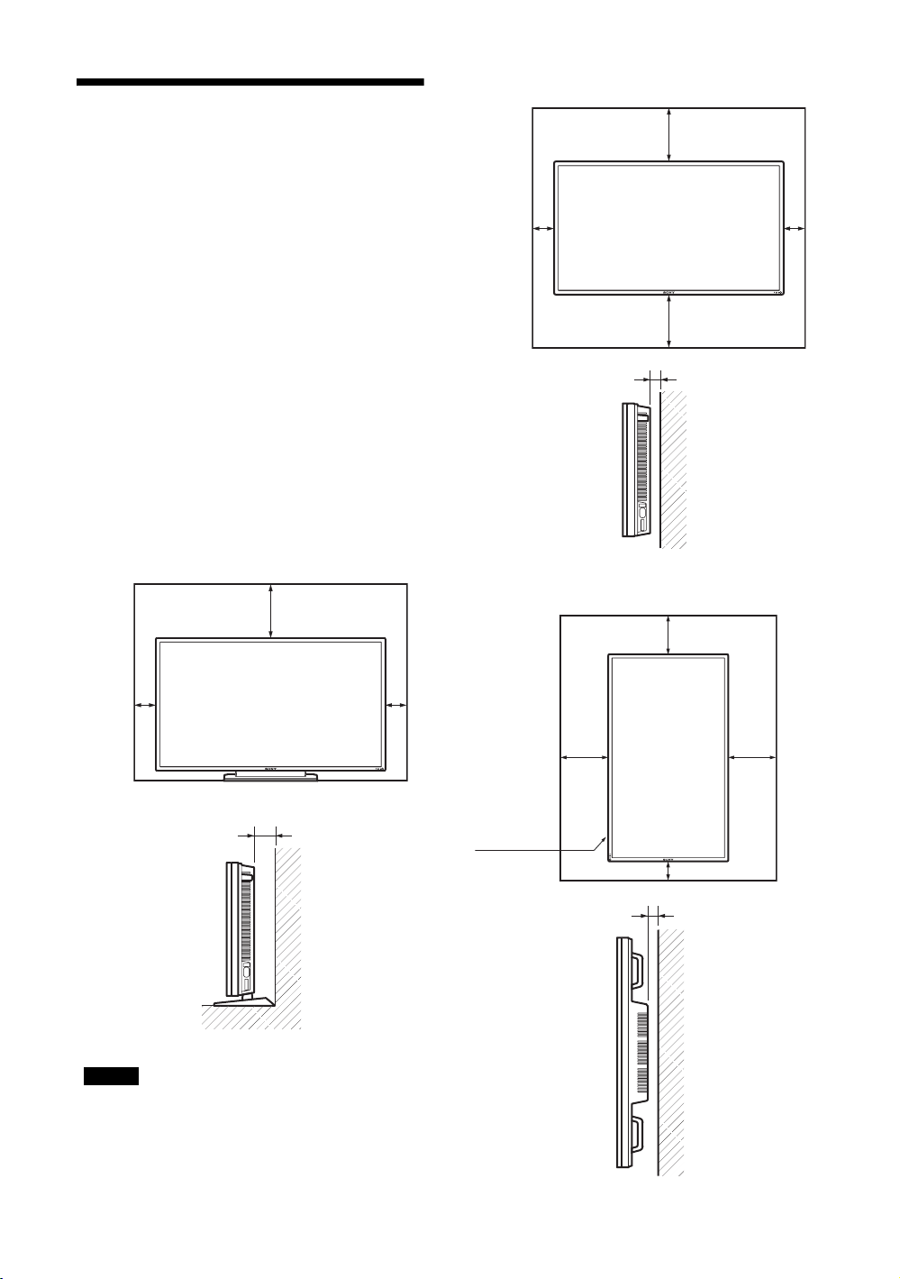
設置するときのご注意
周囲に充分なスペースをとる
・ 内部の温度上昇を防ぐため、密閉状態にならないよ
うにディスプレイの周囲に少なくとも下図に示す距
離をあけて、通風を確保してください。
・ 周囲の温度は 0℃〜 35℃の範囲でご使用ください。
天井付近に設置する場合、周囲の温度は室温より高
くなることがありますのでご注意ください。
・ スタンドを使用するときは、専用テーブルトップス
タンド SU-S01(別売)をご使用ください。取り付
け方法については、テーブルトップスタンドの取扱
説明書をご覧ください。
・ ブラケットやネジ、ボルトなどの設置機材について
特定の製品を指定することはできません。実際の設
置は、お買い上げ店またはソニーのサービス窓口に
ご依頼ください。設置についてはソニーのサービス
窓口にご相談ください。
・ 通電中は高温になる部分があり、やけどの原因とな
ります。通電中やスタンバイにした直後は、本機の
上面、後面には手を触れないでください。
水平方向で使用する場合
前面
25
10 10
25
側面
5
テーブルトップスタンドを使用する場
合
前面
25
10
側面
10
10
単位:cm
垂直方向で使用する場合
前面
設置の際
は、必ず1
(POWER)
スイッチを
左下にして
ください。
側面
25
20
10
単位:cm
25
5
ご注意
スタンド(別売)を取り付けたままの状態で、運搬
や設置を行うときは、2 人以上で作業してください。
JP
10
単位:cm
Page 11
各部の名称と働き
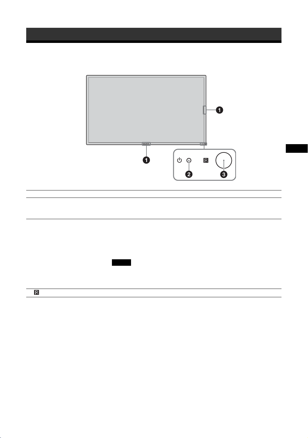
前面
名称 説明
1ソニーロゴ ソニーロゴが点灯します。
メニュー画面で、自動から各種手動設定にすることができます。34 ペー
ジの「ロゴ」をご覧ください。
21(電源 / スタンバイ)インジ
ケーター
3 リモコンセンサー リモコンの受光部です。
・ 本機の電源を入れると緑色に点灯します。
・ 本機がスタンバイ状態のとき、赤色に点灯します。また PC 入力のと
き、パワーセービング状態になると、インジケーターがオレンジ色に
点灯します。
1 インジケーターが赤色で点滅したときは、40 ページをご覧くださ
い。
ご注意
「マルチディスプレイ設定」の「LED」が「切」で、「ポジション設定」
が右下以外の場合は、ディスプレイの電源が入っていてもインジケー
ターは緑点灯しません(無信号時 / 未対応信号時を除く)。
JP
11
JP
Page 12
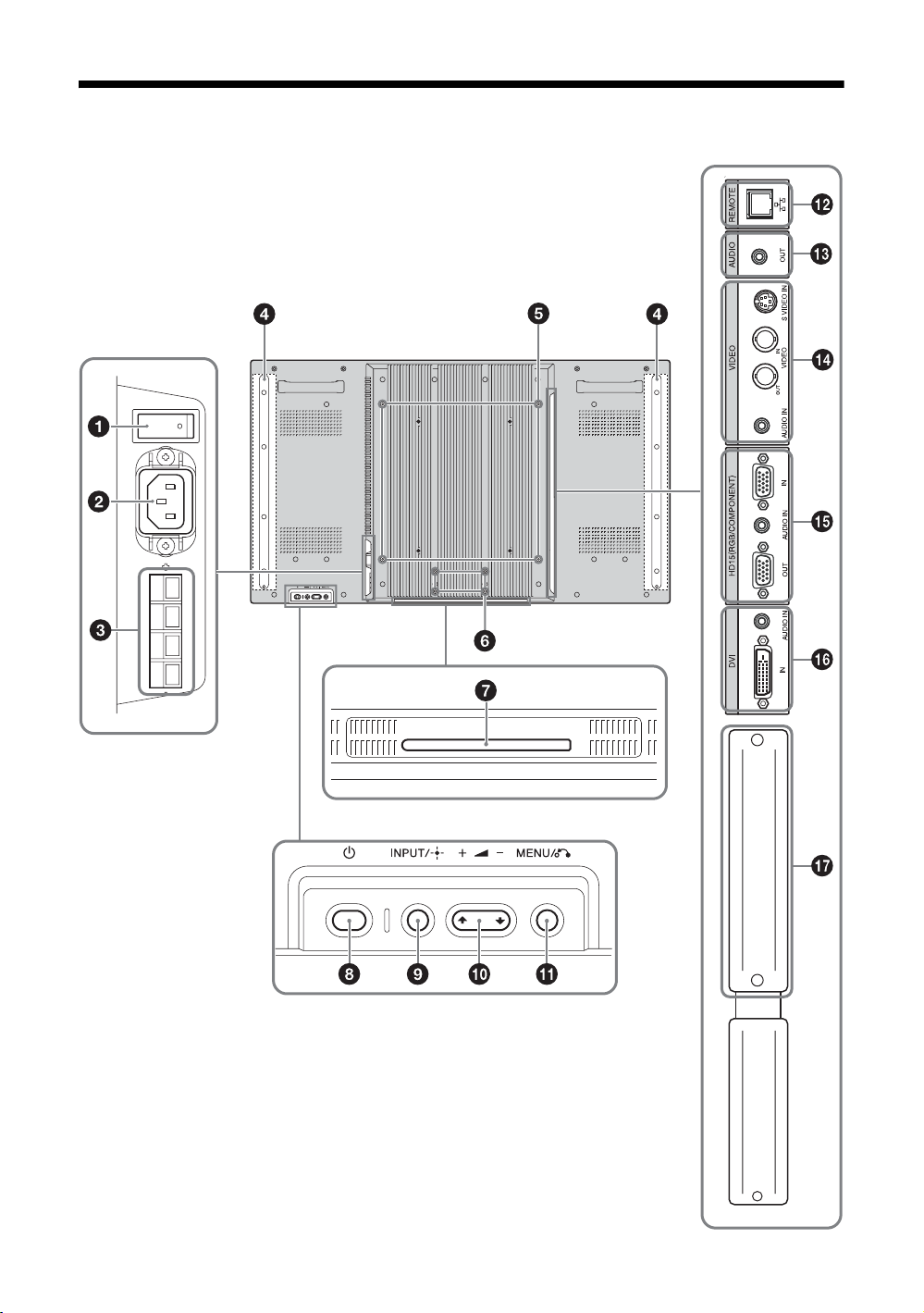
後面
* イラストは FWD-S47H1 のものを使用しています。
JP
12
Page 13
名称 説明
1主電源スイッチ 本機設置時には「入」( 側を押す)にします。
「切」( 側を押す)にすると、消費電力を0Wにすることができます。
2ACIN(電源入力)ソケット 付属の電源コードをこのソケットとコンセントに接続します。21 ページ
をご覧ください。
電源コードを接続し、主電源スイッチを「入」にすると、1 インジケー
ターが赤色に点灯し、本機はスタンバイ状態になります。
3SPEAKER(スピーカー)端子スピーカー SS-SPG01(別売)をこの端子に接続します。スピーカーの
接続について詳しくは、スピーカーに付属の取扱説明書をご覧の上、正
しく接続してください。
また、スピーカーコードのまとめかたは、22 ページをご覧ください。
4スピーカー取り付け位置 専用スピーカー SS-SPG01 を取り付けます。
5スタンド取り付け用穴 VESA 規格に準拠したネジ穴です。(ピッチ:400mm × 400mm, ネ
ジ:M6)
6専用ディスプレイスタンド取り
付け用穴
7専用ディスプレイスタンド装着
穴カバー
81(POWER)スイッチ 本機の電源を入 / 切(スタンバイ)します。
9INPUT/ (ENTER)ボタン INPUT または OPTION 端子に接続した機器からの入力信号を選びま
0+/–/F/f(音量調節 / カーソル
移動)ボタン
qaMENU/ (RETURN)ボタン 画面にメニューを出すときに使用します。また、ひとつ前のメニュー画
qsREMOTE
(10BASE-T/100BASE-TX)
ディスプレイスタンドSU-S01(別売)を取り付けるときに使用します。
ディスプレイスタンドSU-S01(別売)を取り付けるときに外します。
主電源スイッチが「入」( 側)の状態で操作してください。
す。
の順に入力信号を切り換えます。
OPTION スロットに映像系のオプションアダプターがないときは、ス
キップします。
また、メニューで設定した内容を確定するときに使用します。
スピーカーから出る音量を調節するときに使用します。また、メニュー
を表示しているときは、カーソルの移動や数値などの設定をするときに
使用します。
面に戻るときに使用します。
本機を 10BASE-T/100BASE-TX の LAN ケーブルでネットワークと接続
します。PC からネットワーク経由でディスプレイのコントロールおよ
び各種設定ができます。
JP
qdAUDIO
(ステレオミニジャック)
ご注意
・ LAN ケーブルご使用の際は、輻射ノイズによる誤動作を防ぐため、付
属のケーブルを使用してください。
・ 安全のために、周辺機器を接続する際は、過大電圧を持つ可能性があ
るコネクターをこの端子に接続しないでください。
接続については本書の指示に従ってください。
・ 本端子を使用する際は、「ネットワークポート」の「本体」を選択し
てください(34 ページ)。
外部機器用音声モニター出力端子です。AUDIO 端子に入力した音声信
号の、画面に表示されている信号の音声を出力します。2画面(P&P、
PinP)のときは、アクティブ * 画面の音声信号を出力します。
ご注意
・「音質モード」、「スピーカー出力」の設定は反映されません。
・ リモコンで設定した消音状態は反映されません。
13
JP
Page 14

名称 説明
qfVIDEO SVIDEOIN(ミニ DIN4 ピン):映像機器の S ビデオ信号出力端子と接
続します。
VIDEOIN(BNC 型):映像機器のビデオ信号出力端子と接続します。
VIDEOOUT(BNC 型):映像機器のビデオ信号入力端子と接続します。
VIDEOIN の映像を出力します。
AUDIOIN(ステレオミニジャック):映像機器の音声出力端子と接続し
ます。
qgHD15
(RGB/COMPONENT)
(D-sub15 ピン)
qhDVI
(DVI-D24 ピン)
qjOPTION スロット
(VIDEO/COM ポート)
HD15(RGB/COMPONENT)IN:映像機器や PC のアナログ RGB 信号出
力端子、またはコンポーネント信号出力端子と接続します。45 ページを
ご覧ください。
AUDIOIN:音声信号を入力します。映像機器や PC の音声出力端子と
接続します。
HD15(RGB/COMPONENT)OUT:映像機器や PC のアナログ RGB 信号
入力端子、またはコンポーネント信号入力端子と接続します。45 ページ
をご覧ください。上記 HD15(RGB/COMPONENT)IN 端子から入力さ
れた信号を出力します。
ご注意
・ コンポーネント信号を入力する際は 13、14 ピンに同期信号を入力し
ないでください。画像が正しく表示されない場合があります。
・ 本機がスタンバイ状態のときや AC 電源が接続されていないときは、
HD15(RGB/COMPONENT)OUT 端子からは出力されません。
DVIIN:映像機器や PC などのデジタル信号出力端子と接続します。
HDCP のコンテンツ保護に対応しています。
AUDIOIN:音声信号を入力します。映像機器などの音声出力端子と接
続します。
映像信号および通信機能に対応したスロットです。オプションアダプ
ター(BKM-FWシリーズなど)を装着すると、本機の機能を拡張する
ことができます。20 ページをご覧ください。
* 音声が出力され、入力の切り換えが可能な状態
14
JP
Page 15
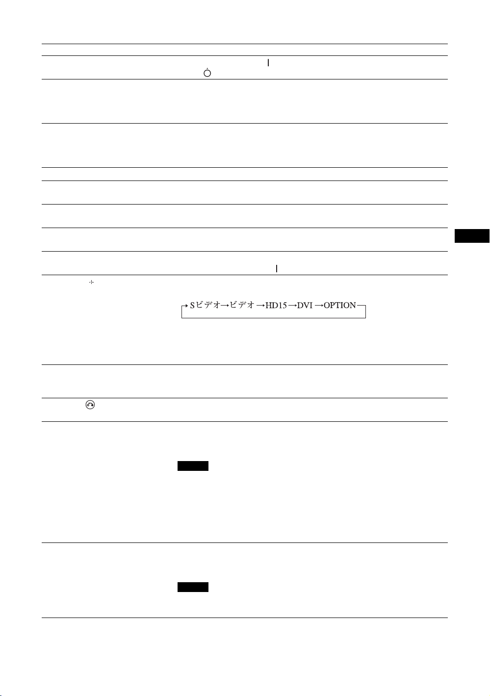
リモコン
ボタンの機能
1 POWER(電源)ON スイッチ
押すと電源が入ります。
本機後面にある主電源スイッチが「入」の状態で操作してく
ださい。
2 DVIボタン
DVI 端子に接続した機器からの入力信号を選びます。
3 SVIDEOボタン
SVIDEOIN 端子に接続した映像機器からの入力信号を選び
ます。
4 VIDEOボタン
VIDEOIN 端子に接続した映像機器からの入力信号を選びま
す。
5 PICTURE ボタン
「画質モード」を切り換えます。ボタンを押すごとに、「ダイ
ナミック」、「スタンダード」、「カスタム」、「カンファレン
ス」、「TCControl」の順に切り換わります。
6 F/f/G/g/ ボタン
F/f/G/g
値などを設定します。 ボタンを押すと、選んだメニュー
や設定した内容を確定します。
「2 画面」モードでは、2 画面設定を変更することができま
す。18 ページをご覧ください。
7 ボタン
画面のアスペクト比を変更します。17 ページをご覧くださ
い。
8 MENU ボタン
画面にメニューを出すときに使用します。もう一度押すとメ
ニューが消えます。23 ページをご覧ください。
ボタンでメニューのカーソルを移動させたり、数
JP
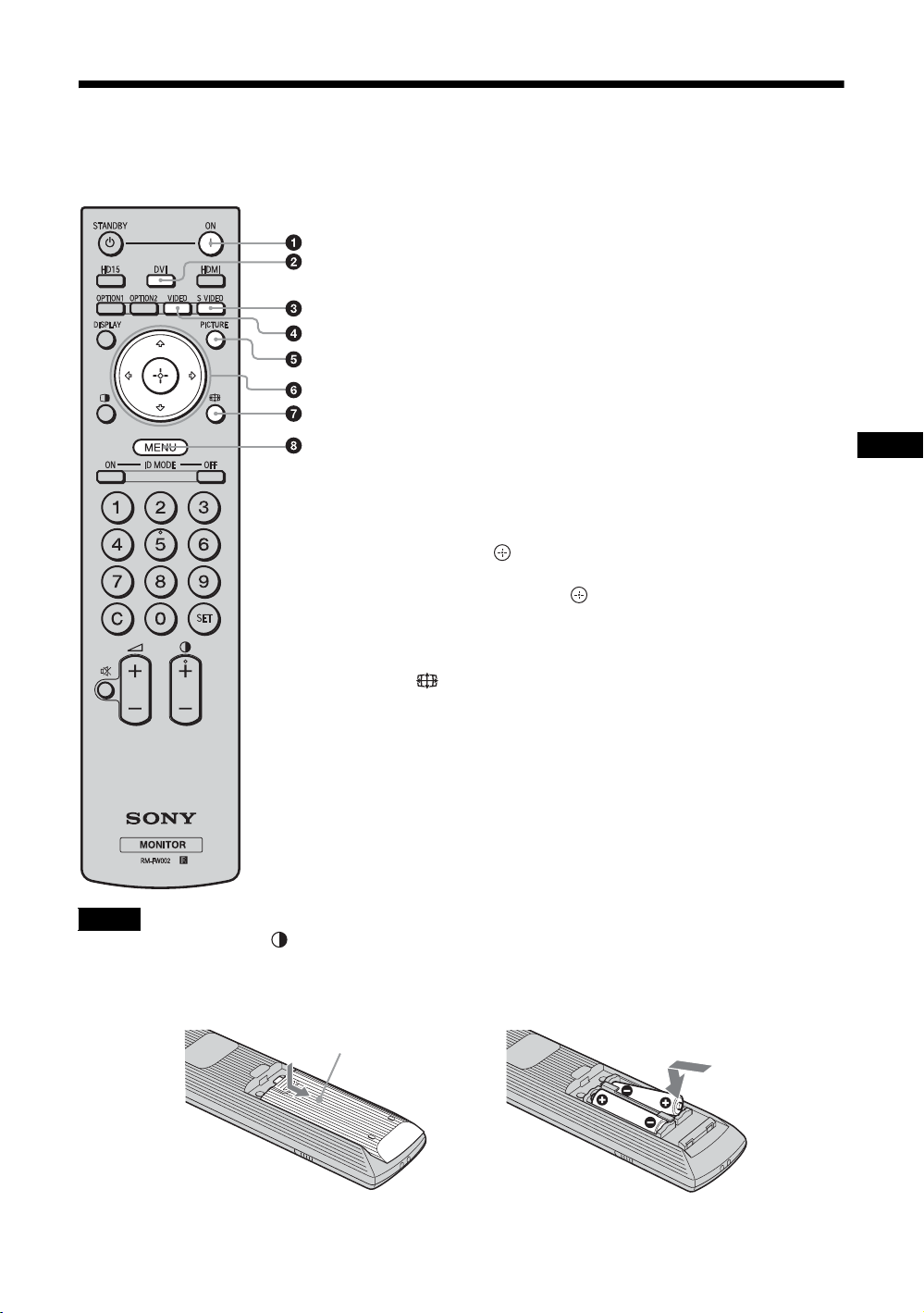
ご注意
・ 数字ボタンの「5」および ボタンには、凸部(突起)が付いています。操作の目印としてお使いください。
・ 付属の単 3 形乾電池 2 本を、リモコンの電池挿入部内部の図を確認しながら、3 極と # 極を正しく入れてくだ
さい。
・ 指定以外の電池に交換すると、破裂する危険があります。必ず指定の電池に交換してください。使用済みの電
池は、国または地域の法令に従って処理してください。
押してスライドさせて開け
,
15
JP
Page 16
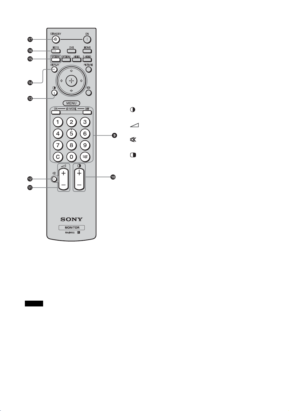
9 IDMODE(ON/0-9/SET/C/OFF)ボタン
複数のディスプレイを使用しているとき、「インデックス番
号」を指定して、特定のディスプレイのみを操作することが
できます。
・ ON ボタン:「インデックス番号」を画面上に表示します。
・ 0-9 ボタン:操作したいディスプレイの「インデックス番
号」を入力します。
・ SET ボタン:入力した「インデックス番号」を設定しま
す。
・ C ボタン:入力した「インデックス番号」をクリアしま
す。
・ OFF ボタン:通常の画面に戻ります。
19 ページをご覧ください。
0 +/–ボタン
画像のコントラストを調整します。
qa +/–ボタン
音量を調整します。
qs ボタン
音を消します。もう一度押すと、音が出ます。
qd ボタン
「2 画面」モードを切り換えます。ボタンを押すごとに、
「P&P」、「PinP」、1画面の順に切り換わります。18 ページを
ご覧ください。
qf DISPLAY ボタン
現在選択されている入力、入力されている信号の種類および
「アスペクト」設定を画面に表示します。もう一度押すと表
示は消えます。表示された状態でしばらくたつと自動的に表
示は消えます。
qg OPTION1 ボタン
オプションアダプターを装着した際、そこに接続した機器か
らの入力信号を選びます。
装着したオプションアダプターに入力が複数ある場合は、ボ
タンを押すたびに入力が切り換わります。
qh HD15 ボタン
HD15(RGB/COMPONENT) 端子に接続した機器からの入力
信号を選びます。メニューの設定により RGB 信号かコン
ポーネント信号の自動選択またはマニュアル選択ができま
す。
qj STANDBY ボタン
押すとスタンバイ状態になります。
ご注意
本機では HDMI ボタンおよび OPTION 2ボタンは使用しません。
JP
16
Page 17
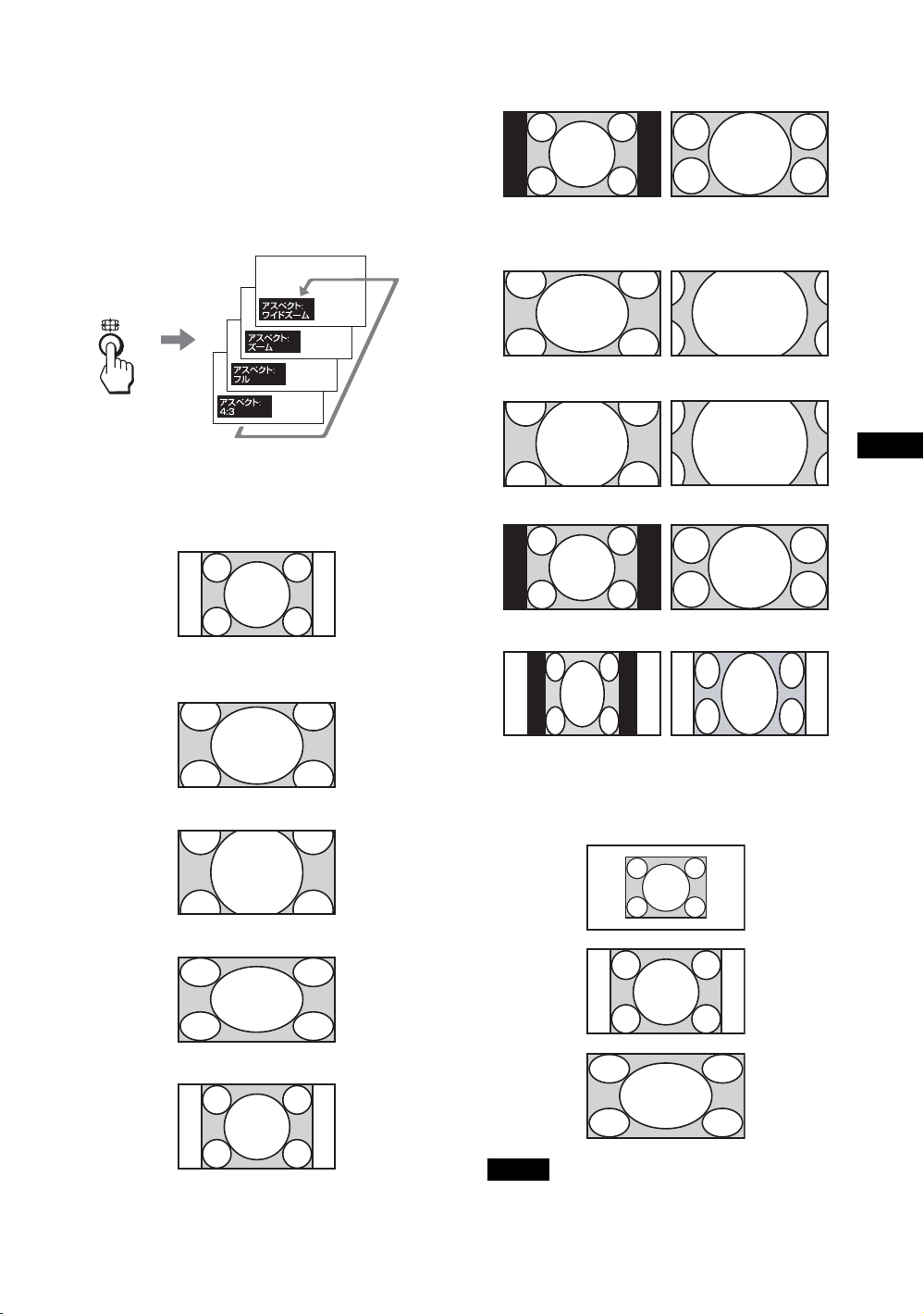
リモコンの特別ボタン
ワイド切換を使う
画面のアスペクト比を変更することができます。
ちょっと一言
「画面」メニューからも「アスペクト」を設定するこ
とができます。30、31 ページをご覧ください。
16:9 の映像ソース
m
ワイドズーム
ズーム
ビデオ、DVD などの映像機器からの入力の場
合(PC 入力以外)
4:3 の映像ソース
m
ワイド
ズーム
ズーム
フル
JP
フル
4:3
PC 入力の場合
以下のイラストは解像度 800 × 600 の入力を
行った場合です。
リアル
フル 1
4:3
フル 2
ご注意
パネル解像度(1,920×1,080)より高い解像度の信号
を入力した場合、リアルはフル 1 と同じように表示し
ます。
17
JP
Page 18
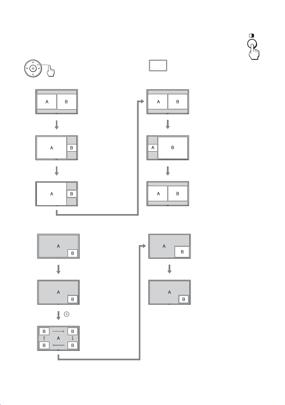
2 画面設定を使う
PC とビデオなど、ふたつの異なる信号の映像を、並べて表示します。またアクティブ
な画面の入れ換えや、画面の大きさのバランスも自由に変えられます。
また「画面」メニューからも「2画面設定」を設定することができます。
28 ページをご覧ください。
アクティブな画面を示すカーソル
P&P の場合
AとBの横幅は同
じになります。
高さは各画像のアス
ペクト比によって決
まります。
A と B の横幅は同じにな
ります。
高さは各画像のアスペク
ト比によって決まります。
PinP の場合
Gボタンを押す
A の横幅は B の横幅
より大きくなりま
す。
A のアスペクト比が
4:3 なら、A の高さ
はパネルのサイズと
等しくなります。
g
ボタンを押す
右側の B がアクティ
ブな画像となりま
す。
g
ボタンを押す
主画面 (A) の中に副
画面 (B) が表示され
ます。
G
/gボタンを押す
副画面 (B) がアク
ティブな画像となり
ます。
gボタンを押す
B の横幅は A の横幅より大
きくなります。
B のアスペクト比が 4:3
なら、B の高さはパネルの
サイズと等しくなります。
f
ボタンを押す
右側の B がアクティブな画
像のまま、小さくなりま
す。
副画面 (B) の画面が大き
くなります。
f
ボタンを押す
副画面 (B) の画面が小さく
なります。
ボタンを押す
副画面 (B) の位置が
移動します。
F
ボタンを押す
ちょっと一言
・ アクティブな画面を示すカーソルは、5秒たつと表示が消えます。
・ 画面の大きさは 15 段階で変えられます。(P&P の場合)
JP
18
Page 19
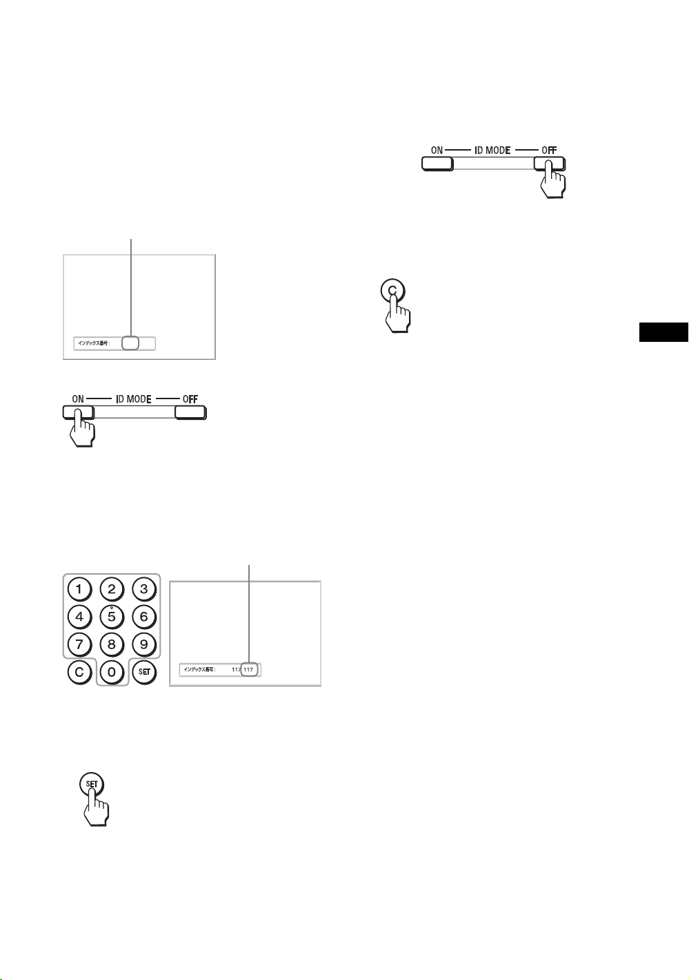
IDMODE ボタンを使う
複数のディスプレイを使用しているとき、「イ
ンデックス番号」を指定して、特定のディスプ
レイのみを操作することができます。
1 ON ボタンを押す。
「インデックス番号」が、画面左下のメ
ニューに黒い文字で表示されます(「イン
デックス番号」は、1 から 255 の範囲で、あ
らかじめ各ディスプレイに設定されていま
す)。
インデックス番号
4 設定変更などの操作が終了したら、OFF
ボタンを押す。
ディスプレイは通常の画面に戻ります。
インデックス番号を訂正するには
C ボタンを押して、現在入力されている「イン
デックス番号」を消去します。手順 2 に戻り、
新しい「インデックス番号」を入力します。
117
2 リモコンの 0 から 9 のボタンで、操作した
いディスプレイの「インデックス番号」
を入力する。
すべてのディスプレイの「インデックス番
号」の右に、入力した数字が表示されます。
入力された番号
3 SET ボタンを押す。
選択したディスプレイの文字が緑色に変わ
り、その他のディスプレイの文字は赤色に
変わります。
JP
ちょっと一言
ディスプレイの「インデックス番号」を変更するに
は、32 ページの「コントロール設定」の「インデッ
クス番号」をご覧ください。
これで特定のディスプレイ(文字が緑色に
変わったディスプレイ)のみを操作できま
す(POWER(電源)ON スイッチ、
STANDBY ボタン、および IDMODE-OFF
ボタンの操作だけは、ほかのディスプレイ
にも有効です)。
19
JP
Page 20
オプションアダプター
本機側面にある OPTION スロット qj(14 ペー
ジ)の端子部はスロットイン方式になってい
て、以下のオプションアダプター(別売)に付
け換えることができます。
各アダプターの取り付けかたについては、お買
い上げ店またはソニーのサービス窓口にご相談
ください。
機能拡張用オプションアダプターについては、
それぞれの取扱説明書も合わせてご覧くださ
い。
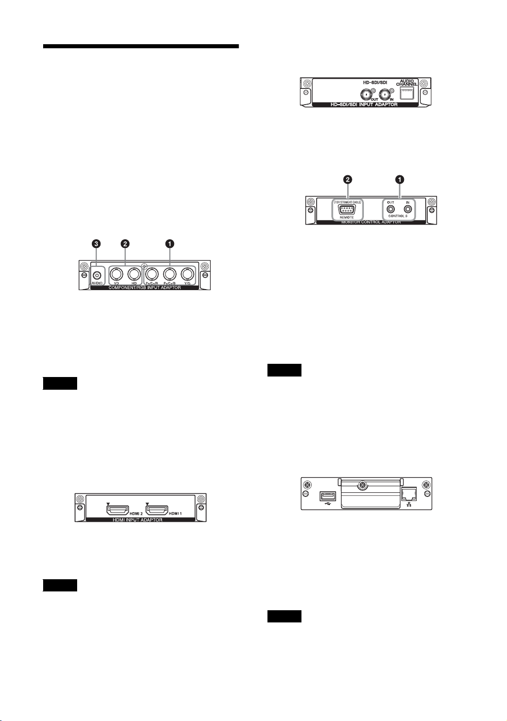
コンポーネント /RGB 入力アダプター
BKM-FW11
1 Y/G,PB/CB/B,PR/CR/R映像入力端子
(BNC 型):映像機器や PC のコンポーネン
ト信号出力端子またはアナログ RGB 信号出
力端子と接続します。
2 HD,VD同期信号入力端子(BNC 型):PC
の同期信号出力端子と接続します。
ご注意
コンポーネント信号を入力する際は HD,VD に同期信
号を入力しないでください。画像が正しく表示されな
い場合があります。
3 AUDIO(音声入力)端子(ステレオミニ
ジャック):音声信号を入力します。映像機
器や PC の音声出力端子と接続します。
HDMI 入力アダプター BKM-FW15
HD-SDI/SDI 入力アダプター
BKM-FW16
映像機器の HD-SDI 信号出力端子と接続しま
す。
モニターコントロールアダプター
BKM-FW21
1 CONTROLSIN/OUT(ミニジャック):
ディスプレイを含む他機器の CONTROLS
端子に接続すると、1台のリモコンで複数の
機器を操作できます。CONTROLSOUT端
子とほかの機器の CONTROLSIN 端子、
CONTROLSIN端子とほかの機器の
CONTROLSOUT端子を接続します。
2 REMOTE(D-sub9ピン):RS-232Cプロ
トコルを使って本機を遠隔操作するときに
使います。詳しくはお買い上げ店またはソ
ニーのサービス窓口にご相談ください。
ご注意
・ REMOTE端子は本機側面にある REMOTE端子
(LAN)qs(13 ページ)と併用することはできませ
ん。
・ REMOTE端子を使用する際は、「ネットワーク
ポート」の「Option」を選択してください
(34 ページ)。
ストリーミングレシーバーアダプター
BKM-FW50
高精細な映像と 2チャンネルのデジタル音声を
お楽しみいただけます。
接続された機器によって、音声/映像機器また
は PCの適切なモードが自動選択されます。
ご注意
HDMI ケーブル(別売)は、必ず HDMI ロゴの付い
たケーブルをご使用ください。
JP
20
本アダプターによって、本ディスプレイを電子
看板(デジタルサイネージ)として活用できま
す。
指定のデータ形式の動画、静止画、BGM が含
まれた記録メディアを差し込むだけで再生が簡
単にできます。また、遠隔地にある PC から
ネットワークを利用してディスプレイへ映像を
表示することもできます。
ご注意
別途コンパクトフラッシュが必要です。
Page 21
接続
接続上のご注意
・ 各機器の電源を切ってから接続を行ってください。
・ 接続ケーブルはそれぞれの端子の形状に合った正し
いものをお選びください。
・ 接続ケーブルは端子にしっかり差し込んでくださ
い。接続が悪いとノイズの原因となります。
・ ケーブルを抜くときは必ずプラグを持って抜いてく
ださい。決してケーブルそのものを引っ張らないで
ください。
・ 接続の詳細については、各機器の取扱説明書をご覧
ください。
・ 電源コードのプラグは、ACIN ソケットに、まっ
すぐ突き当たるまで差し込んでください。
・ 付属の AC プラグホルダーは、使用する電源コード
のプラグが確実に固定できる方を選んでお使いくだ
さい。
スピーカーの接続
スピーカー SS-SPG01(別売)を接続します。
スピーカーの接続について詳しくは、スピー
カーに付属の取扱説明書をご覧の上、正しく接
続してください。また、スピーカーコードのま
とめかたは、22 ページをご覧ください。
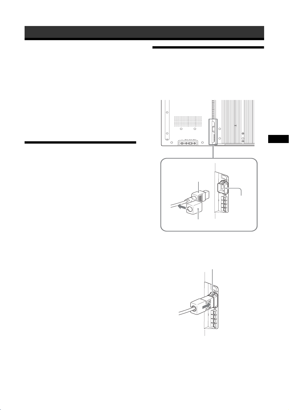
電源コードの接続
1 電源コードを底部の ACIN ソケットに差
し込み、AC プラグホルダー(付属)を電
源コードに取り付ける。
電源コード
ACIN
ソケット
JP
AC プラグ
ホルダー
2 AC プラグホルダーをスライドさせて、本
体側の ACIN ソケットカバーにはめ込
む。
ACIN ソケットカバー
電源コードをはずすには
AC プラグホルダーのつめをはさみ、ロックを
解除してからプラグをつかみ、電源コードをは
ずしてください。
21
JP
Page 22
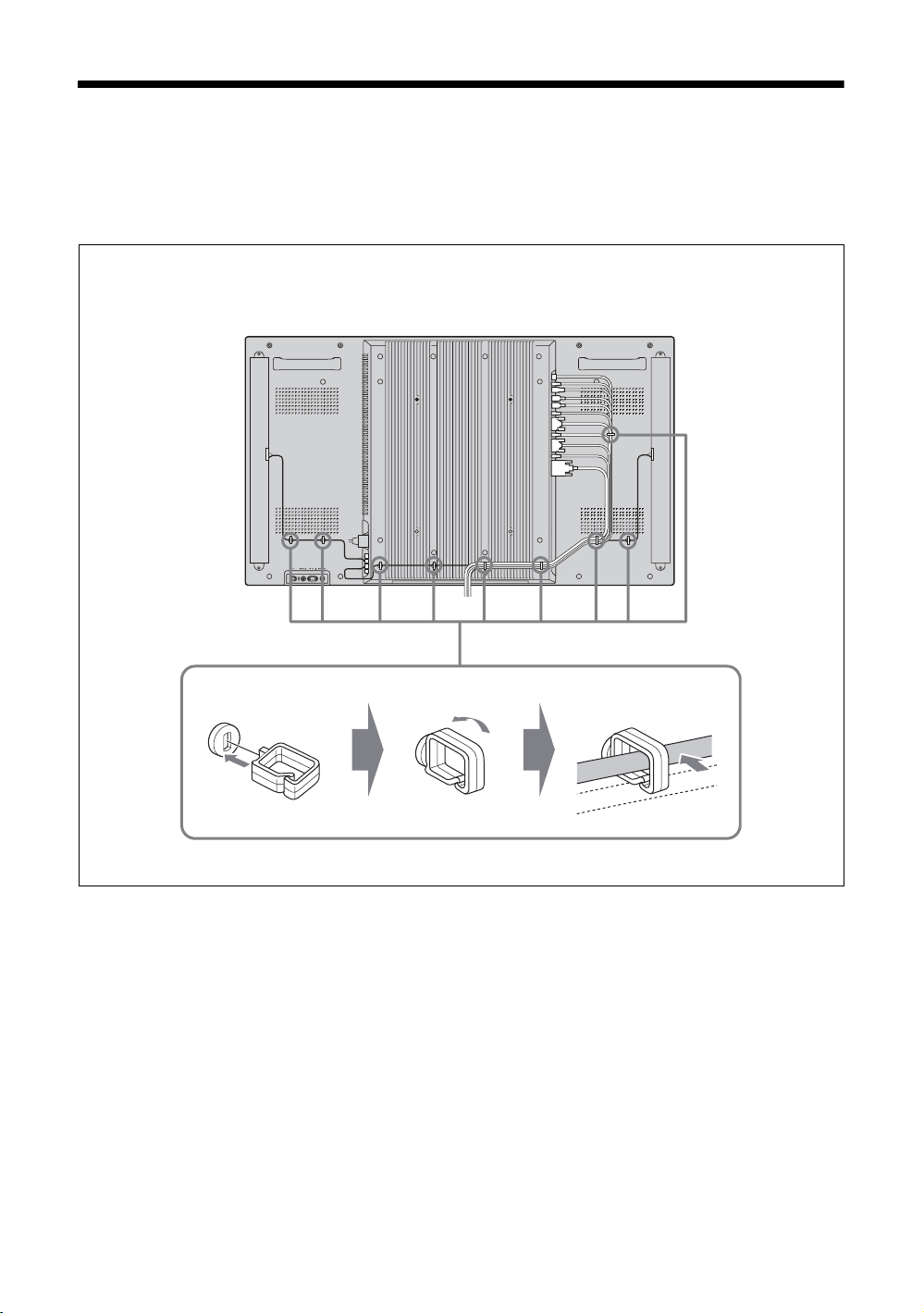
ケーブルを処理する
ケーブルホルダーを使う
付属のケーブルホルダー(× 9)を使って、ケーブル類をすっきりとまとめることができます。ケーブ
ルホルダーは、以下のように取り付けます。
本機後面
321
22
JP
Page 23
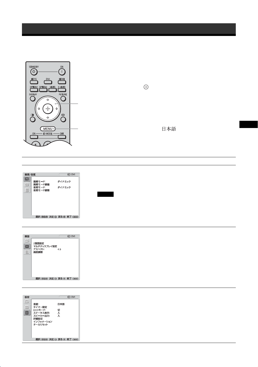
メニューの設定
メニュー一覧
1 MENU ボタンを押す。
2 F/fボタンで設定したいメニューのアイ
3 ボタンまたはg ボタンを押す。
2,3
メニュー表示の言語を変更する
メニュー表示とメッセージの言語を、
「English」、「Français」、「Deutsch」、「Español」、
1
メニュー画面から以下の項目を設定することができます。
メニュー画面 設定 / 変更できる項目
画質 / 音質
画質モード:(24、26 ページ)
画質モード調整(24、26 ページ)
音質モード:(25、27 ページ)
音質モード調整(25、27 ページ)
「Italiano」、「 」から選びます。
初期設定では「English」(英語)に設定されて
います。
32 ページをご覧ください。
コンを選ぶ。
メニューの操作を終了するには、MENU ボ
タンを押します。
JP
画面
設定
ご注意
信号が無入力の時は「画質モード」と「画質モード調整」の設定 / 変更は
できません。
2 画面設定(28、31 ページ)
マルチディスプレイ設定(29、31 ページ)
アスペクト:(30、31 ページ)
画面調整(30、31 ページ)
言語:(32 ページ)
タイマー設定(32 ページ )
ECO モード:(32 ページ)
ステータス表示:(32 ページ)
スピーカー出力:(32 ページ)
詳細設定(32 ページ)
インフォメーション(34 ページ)
オールリセット(34 ページ)
* メニュー画面の下の行に表示されているアイコンは、設定項目によっては、働かないことがあります。
23
JP
Page 24
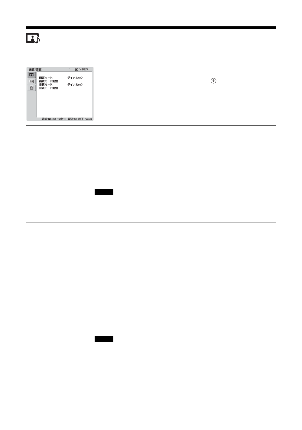
画質 / 音質メニュー
ビデオ入力の場合
項目を選んで設定を変えるには、F/f/G/g ボ
タンを押します。
設定を確定するには ボタンを押します。
「画質 / 音質」メニューには、以下の項目が含
まれます。
画質モード
画質モード調整
「ダイナミック」:映像の輪郭を強調しコントラストを最大限に上げます。
「スタンダード」:標準的な設定です。
「カスタム」:お好みに合わせて細かく調整できます。
「カンファレンス」:蛍光灯下でのビデオ会議に適した画質になります。
「TCControl」:設定は「ダイナミック」と共通です。加えて「TrueColor
Control」機能(後述)が使用可能となります。
ちょっと一言
リモコンの PICTURE ボタンでも「画質モード」の設定を切り換えることができま
す。
ご注意
・「カンファレンス」は、ご使用の環境やビデオ会議システムによっては効果が少
ない場合があります。その場合は画質調整をしたり、他の「画質モード」の設定
に切り換えるなどしてください。
・「TCControl」においては「明るさ強調」は Off で固定です。
「バックライト」:液晶画面の明るさを調整します。
「コントラスト」:コントラストの強弱を調整します。
「明るさ」:映像の明るさを調整します。
「色の濃さ」:色の濃淡を調整します。
「色あい」:映像の色調を調整します。
「シャープネス」:映像の輪郭の強弱を調整します。
「NR」:接続した機器からのノイズを軽減します。「切」、「低」、「中」、
「高」から強弱を設定することができます。
「シネモーション」:「自動」を選ぶと、映画の映像素材を検知し、リバー
ス 3-2プルダウンまたはリバース 2-2プルダウン処理によって画面表示を
自動的に最適化します。
動画がより鮮明かつ自然に見えます。「切」を選ぶと、この検知を行いま
せん。
「ダイナミックピクチャー」:「入」を選ぶと白をより白く、黒をより黒く
してコントラストを強めます。
「ガンマ補正」:映像の明暗部分のバランスを調整することができます。
「高」、「中」、「低」から強弱を設定することができます。
ご注意
・「オプション」は DVI 入力の時のみ設定できます。
・ 医用におけるデジタル画像と通信(DICOM)規格のグレースケール標準関数
(GSDF) に基づいたガンマ設定です。但し、本設定は参考用であり、医療診断に
は使えません。
「色温度」:お好みに合わせて、白色の色調を調整できます。工場出荷時は
初期値が各色温度に調整されています。
「高」:青みがかった白色になります。
「中」:中間の白色になります。
「低」:赤みがかった白色になります。
24
JP
Page 25

「カスタム」:上記より広い範囲で白色の色調を調整し設定することが
できます。
ちょっと一言
色調調整画面で「標準」を選択すると工場出荷時の設定に戻すことができます。
「明るさ強調」:明るさを強調した画質になります。
ご注意
・「明るさ強調」を「入」にしたときは、「バックライト」、「コントラスト」、「明る
さ」、「色温度」の設定は変更できません。
・「明るさ強調」が「入」で、なおかつ「ECO モード」が「切」のときに輝度が最
大となります。
「TrueColorControl」:赤、緑、黄、青の4色それぞれについて色合いと鮮
やかさを調整することで、画像の中の特定の色を強調することができま
す。
調整したい色を選択すると、現在の画像でどの部分が調整されようとして
いるのかを視認した後、ダイアログボックス上のマトリクスでその色を調
整することができます。
ご注意
・ この項目は「画質モード」が「TCControl」の場合に調整することができます。
・ 画面モード時は、この設定を行うことはできません。たとえ 1画面時に設定して
も、「2画面モード時」には反映されない場合があります。
「標準」:「画質モード調整」のすべての設定項目を初期設定に戻します。
ご注意
・ 入力信号がビデオまたは S ビデオで、映像信号のカラー方式が NTSC でない場
合、「色あい」は調整できません。
・「画質モード」が「カンファレンス」または「TCControl」の場合「ダイナミッ
クピクチャー」は調整できません。
・ それぞれの「画質モード」で設定や調整を行うことができますが、「バックライ
ト」「NR」「シネモーション」はすべての画質モードで共通となります。
・ 2 画面モード時には「ダイナミックピクチャー」および「シネモーション」は機
能しません。
音質モード
各種「音質モード」によって、スピーカー SS-SPG01(別売)から出力さ
れる音声を調整できます。
「ダイナミック」:高音と低音を強調します。
「スタンダード」:標準的な設定です。
「カスタム」:お好みに合わせて細かく調整できます。
音質モード調整
「高音」:高音の強弱を調整します。
「低音」:低音の強弱を調整します。
「バランス」:スピーカーの左右出力バランスを調整します。
「サラウンド」:映像の種類に合わせて、サラウンドモードを選ぶことがで
きます。
「切」:サラウンド出力をしません。
「ホール」:映画や音楽などのステレオ音声をより臨場感のある音にし
ます。
「シミュレート」:通常の放送やニュース番組のモノラル音声を擬似的
にステレオ音声にして臨場感を高めます。
「標準」:「音質モード調整」のすべての設定項目を初期設定に戻します。
ちょっと一言
・ それぞれの「画質モード」ごとに、「画質モード調整」(「コントラスト」、「明るさ」、「色の濃さ」など)を設定する
ことができます。
・「音質モード」で「カスタム」を選択しているときは、「音質モード調整」(「高音」、「低音」)を設定することがで
きます。
ご注意
「2 画面」モード時は、アクティブな画面の「画質/音質」メニューのみを調整します。
JP
25
JP
Page 26
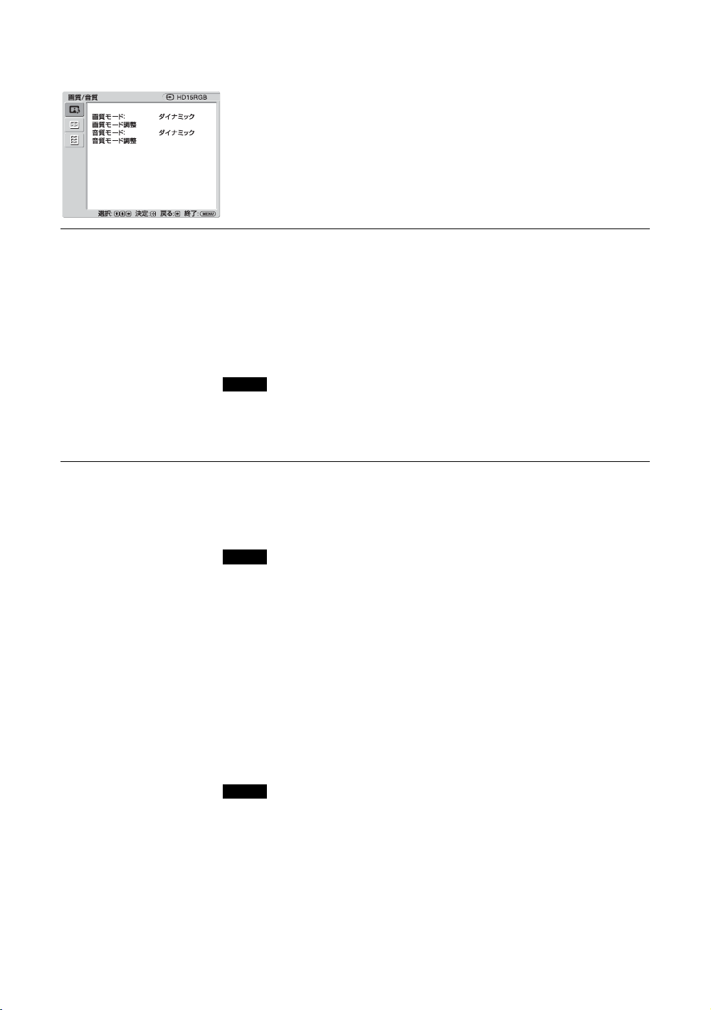
PC 入力の場合
入力を PC 入力に切り換えた場合、PC 用の「画
質 / 音質」メニューとなります。
PC 用の「画質 / 音質」メニューには、以下の
項目が含まれます。
画質モード
画質モード調整
「ダイナミック」:映像の輪郭を強調しコントラストを最大限に上げます。
「スタンダード」:標準的な設定です。
「カスタム」:お好みに合わせて細かく調整できます。
「カンファレンス」:蛍光灯下でのビデオ会議に適した画質になります。
「TCControl」:設定は「ダイナミック」と共通です。加えて「TrueColor
Control」機能(後述)が使用可能となります。
ちょっと一言
リモコンの PICTURE ボタンでも「画質モード」の設定を切り換えることができま
す。
ご注意
・「カンファレンス」は、ご使用の環境やビデオ会議システムによっては効果が少
ない場合があります。その場合は画質調整をしたり、他の「画質モード」の設定
に切り換えるなどしてください。
・「TCControl」においては「明るさ強調」は Off で固定です。
「バックライト」:液晶画面の明るさを調整します。
「コントラスト」:コントラストの強弱を調整します。
「明るさ」:映像の明るさを調整します。
「ガンマ補正」:映像の明暗部分のバランスを調整することができます。
「高」、「中」、「低」から強弱を設定することができます。
ご注意
・「オプション」は DVI 入力の時のみ設定できます。
・ 医用におけるデジタル画像と通信(DICOM)規格のグレースケール標準関数
(GSDF) に基づいたガンマ設定です。但し、本設定は参考用であり、医療診断に
は使えません。
「色温度」:お好みに合わせて、白色の色調を調整できます。工場出荷時は
初期値が各色温度に調整されています。
「高」:青みがかった白色になります。
「中」:中間の白色になります。
「低」:赤みがかった白色になります。
「カスタム」:上記より広い範囲で白色の色調を調整し設定することが
できます。
ちょっと一言
色調調整画面で「標準」を選択すると工場出荷時の設定に戻すことができます。
「明るさ強調」:明るさを強調した画質になります。
ご注意
・「明るさ強調」を「入」にしたときは、「バックライト」、「コントラスト」、「明る
さ」、「色温度」の設定は変更できません。
・「明るさ強調」が「入」で、なおかつ「ECO モード」が「切」のときに輝度が最
大となります。
「TrueColorControl」:赤、緑、黄、青の4色それぞれについて色合いと鮮
やかさを調整することで、画像の中の特定の色を強調したりすることがで
きます。
26
JP
Page 27

調整したい色を選択すると、現在の画像でどの部分が調整されようとして
いるのかを視認した後、ダイアログボックス上のマトリクスでその色を調
整することができます。
ご注意
・ この項目は「画質モード」が「TCControl」の場合に調整することができます。
・ 画面モード時は、この設定を行うことはできません。たとえ 1画面時に設定して
も、「2画面モード」時には反映されない場合があります。
「標準」:「画質モード調整」のすべての設定項目を初期設定に戻します。
ご注意
それぞれの「画質モード」で設定や調整を行うことができますが、「バックライト」
はすべての画質モードで共通となります。
音質モード
各種「音質モード」によって、スピーカー SS-SPG01(別売)から出力さ
れる音声を調整できます。
「ダイナミック」:高音と低音を強調します。
「スタンダード」:標準的な設定です。
「カスタム」:お好みに合わせて細かく調整できます。
音質モード調整
「高音」:高音の強弱を調整します。
「低音」:低音の強弱を調整します。
「バランス」:スピーカーの左右出力バランスを調整します。
「サラウンド」:映像の種類に合わせて、サラウンドモードを選ぶことがで
きます。
「切」:サラウンド出力をしません。
「ホール」:映画や音楽などのステレオ音声をより臨場感のある音にし
ます。
「シミュレート」:通常の放送やニュース番組のモノラル音声を擬似的
にステレオ音声にして臨場感を高めます。
「標準」:「音質モード調整」のすべての設定項目を初期設定に戻します。
ちょっと一言
・ それぞれの「画質モード」ごとに、「画質モード調整」(「コントラスト」、「明るさ」、「色の濃さ」など)を設定する
ことができます。
・「音質モード」で「カスタム」を選択しているときは、「音質モード調整」(「高音」、「低音」)を設定することがで
きます。
ご注意
・「色の濃さ」
時は調整できません。
・「2 画面」モード時は、アクティブな画面の「画質/音質」メニューのみを調整します。
、「色あい」、「シャープネス」、「NR」、「シネモーション」、「ダイナミックピクチャー」は、PC 入力
JP
27
JP
Page 28
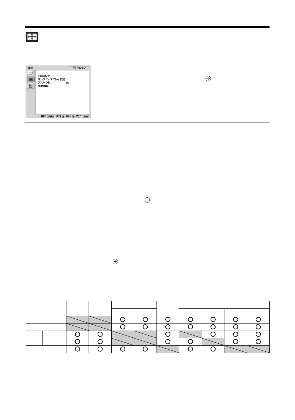
画面メニュー
ビデオ入力の場合
項目を選んで設定を変えるには、F/f/G/g ボ
タンを押します。
設定を確定するには ボタンを押します。
「画面」メニューには、以下の項目が含まれま
す。
2 画面設定
PCとビデオなど、ふたつの異なる信号の映像を、並べて表示します。
「2 画面」
P&P の場合
「操作画面」:操作する画面を選びます。
「画面サイズ」:左右の画面の大きさのバランスを調整します。G/gボタン
を押しながら調整し、 ボタンを押して決定します。(18 ページ)
PinP の場合
「操作画面」:操作する画面を選びます。
「画面サイズ」:副画面の大きさを設定します。「大」、「小」のどちらかを
選びます。
「画面位置」:副画面を表示させたい位置を設定します。
で選び、 ボタンで設定します。
ちょっと一言
「2 画面」モード時は、アスペクト設定の変更ができません。「2 画面」モード選択直
前のアスペクトで表示します。
利用可能な 2 画面の組み合わせ
「切」:「2 画面」機能を解除します。
「P&P」:ふたつの映像を同時に並べて表示します。
「PinP」:ふたつの映像を主画面の中に副画面として表示します。
「左操作」:左の画面がアクティブとなり、操作可能になります。
「右操作」:右の画面がアクティブとなり、操作可能になります。
「画面入替」:左右の画面を入れ換えます。
「主操作」:主画面がアクティブとなり、操作可能になります。
「副操作」:副画面がアクティブとなり、操作可能になります。
「画面入替」:主画面と副画面を入れ替えます。
F/f/G/g ボタン
Sビデオ
ビデオ
RGB
RGB/
YUV
コンポーネント
DVI
1)
「RGB/YUV」の「本体」が「YUV」、「Option」が「RGB」に設定されている場合に対応します。
2)
「RGB/YUV」の「本体」が「RGB」、「Option」が「YUV」に設定されている場合に対応します。
ちょっと一言
BKM-FW50 は 2 画面時において上記表の RGB 出力として扱われます。
JP
28
Sビデオ
ビデオ
RGB/YUV
RGB
コンポーネント
DVI
RGB
1)
OPTION
コンポーネント
2)
HDMI
HD-SDI/SDI
Page 29
マルチディスプレ
イ設定
本機を複数台接続して、ビデオウォールを構成するための設定をします。
「マルチディスプレイ」
「切」:1 画面表示になります。
「2 × 2」/「3 × 3」/「4 × 4」:本機を縦横それぞれに2、3、4台と
複数台接続する場合に設定します。
「1 × 2」/「1 × 3」/「1 × 4」:本機を横に2、3、4台と複数台接続
する場合に設定します。
「2 × 1」/「3 × 1」/「4 × 1」:本機を縦に2、3、4台と複数台接続
する場合に設定します。
「ポジション設定」:個々のディスプレイの画面位置を、
F/f/G/g ボタン
で選びます。 ボタンで位置を確定します。
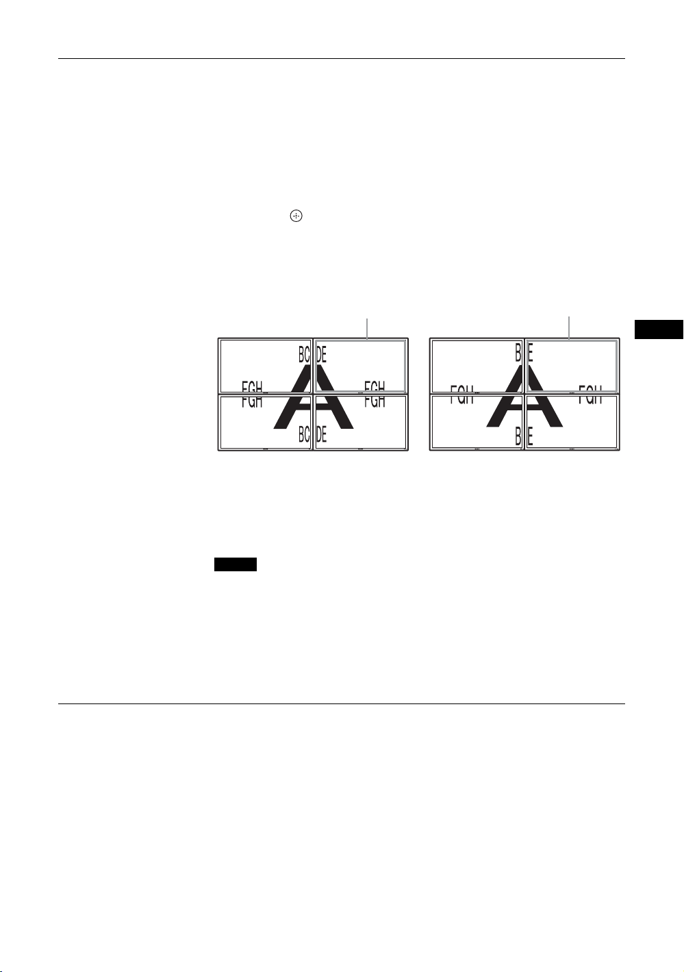
「出画形式」:図にある 2種類の映像出力形式から選びます。いずれかの形
式を選択することにより、水平・垂直位置を手動で調整しなくても、最適
な映像出力が得られます。「タイル」または「ウィンドウ」を選んでくだ
さい。
「タイル」
ジャストスキャン
「ウィンドウ」
オーバースキャン
JP
それぞれの画面に、映像信号を
完全に表示します。
「LED」:「入」を選ぶと、本機前面の
ひとつの大きな映像を、複数の画面
で自然に表示します。
映像信号の一部は、ベゼルの後ろに
隠れます。
1 インジケーター(11 ページ)が点
灯しつづけます。「切」を選ぶと、消灯します。
ご注意
・「マルチディスプレイ」は、ビデオ入力の場合は現在の「アスペクト」を極力維
持した映像を、PC入力の場合は「アスペクト」の「フル 2」の映像を表示するこ
とができます。
・「2 画面」機能を使用していないときにのみ、「マルチディスプレイ設定」を設定
することができます。
・「ポジション設定」を右下に設定すると、「LED」を「切」にしても、
ケーターが緑色に点灯します。インジケーターは、無信号時 / 未対応信号時も含
め、ディスプレイがオフ(スタンバイ)時、異常検出時、スリープ状態時にも点
灯します。
1 インジ
29
JP
Page 30
アスペクト
「ワイドズーム」:ゆがみを最低限に抑えて映像を拡大し、画面いっぱいに
表示します。
「ズーム」:アスペクト比を保ったまま、映像を拡大します。17 ページをご
覧ください。
「フル」:4:3の映像ソース(標準画質)を水平方向に拡大し、画面いっぱ
いに表示します。16:9の映像ソース(高画質)の場合は、そのままのアス
ペクト比で表示します。
「4:3」:すべての映像ソースを 4:3のアスペクト比で表示します。
ちょっと一言
・ リモコンの ボタンでも「アスペクト」の設定を切り換えることができます。
・ 映画などの DVD映像で、黒帯のある映像を画面いっぱいに映して楽しみたいと
きは、「ズーム」を選んでください。
ご注意
「2 画面」機能または「マルチディスプレイ」使用時は、「アスペクト」は設定でき
ません。
画面調整
ご注意
・「画面調整」は、「2 画面」機能使用時は設定できません。
・ 現在の入力が無信号の場合、「画面」メニューの項目は「2 画面設定」と「マルチディスプレイ設定」を除いて、
すべて選択不可能となります。
「水平サイズ」:映像の左右の大きさを調整します。G/g ボタンと ボタ
ンで調整結果を確定します。
「水平位置」:映像の左右の位置を調整します。
調整結果を確定します。
「垂直サイズ」:映像の上下の大きさを調整します。
ンで調整結果を確定します。
「垂直位置」:映像の上下の位置を調整します。
調整結果を確定します。
「標準」:「画面調整」のすべての設定項目を初期設定に戻します。
G/g ボタンと ボタンで
F/fボタンと ボタ
F/f ボタンと ボタンで
30
JP
Page 31

PC 入力の場合
入力を PC 入力に切り換えた場合、PC 用の「画
面」メニューとなります。
PC 用の「画面」メニューには、以下の項目が
含まれます。
2 画面設定
マルチディスプレ
イ設定
アスペクト
画面調整
ビデオ入力時の「2画面設定」(28 ページ)をご覧ください。
ビデオ入力時の「マルチディスプレイ設定」(29 ページ)をご覧ください。
「フル 1」:アスペクト比を保ったまま、映像を画面垂直方向いっぱいに拡
大します。映像の周囲に黒い帯が出ることがあります。
「フル 2」:映像を画面いっぱいに拡大します。
「リアル」:映像を元のままのドット数で表示します。
ご注意
・「2 画面」機能または「マルチディスプレイ設定」使用時は、「アスペクト」は設
定できません。
・ パネル解像度(1,920×1,080)より高い解像度の信号を入力した場合、「リアル」
は「フル 1」と同じように表示します。
「自動調整」:「実行」を選ぶと接続した PCからの入力信号を受けたとき、
自動的に映像の位置や位相を調整します。入力信号の種類によっては、
「自動調整」がうまく働かないことがあります。その場合は、下記の項目を
手動で調整してください。
「画位相」:画面がちらちらしているとき、位相を調整します。
「ドットピッチ」:映像におかしな縞模様が出るとき、ピッチを調整しま
す。
ちょっと一言
「自動調整」、「画位相」、「ドットピッチ」は DVI などのデジタル信号を入力した場
合は選択できません。
「水平サイズ」:映像の左右の大きさを調整します。G/g ボタンと ボタ
ンで調整結果を確定します。
「水平位置」:映像の左右の位置を調整します。G/g ボタンと ボタンで
調整結果を確定します。
「垂直サイズ」:映像の上下の大きさを調整します。
ンで調整結果を確定します。
「垂直位置」:映像の上下の位置を調整します。
調整結果を確定します。
「標準」:「画面調整」のすべての設定項目を初期設定に戻します。
F/fボタンと ボタ
F/f ボタンと ボタンで
JP
ご注意
現在の入力が無信号の場合、「画面」メニューの項目は「2 画面設定」と「マルチディスプレイ設定」を除いて、す
べて選択不可能となります。
31
JP
Page 32

設定メニュー
項目を選んで設定を変えるには、F/f/G/g ボ
タンを押します。
設定を確定するには ボタンを押します。
「設定」メニューには、以下の項目が含まれま
す。
言語
タイマー設定
ECO モード
ステータス表示
スピーカー出力
詳細設定
メニュー表示の言語を、「English」、「Français」、「Deutsch」、「Español」、
「Italiano」、「 」の中から選びます。
時刻合わせ、内蔵時計の表示、およびあらかじめ決めた時間に自動で電源
を入 / 切するタイマー機能の設定をすることができます。
「時刻設定」:年月日と時刻を設定します。
「日付設定」:年月日を設定します。曜日は自動的に設定されます。
「時間設定」:時刻を設定します。
「時計表示」:「入」を選ぶと、リモコンのディスプレイボタンを押したと
きに設定された現在時刻を表示します。
「電源タイマー」:自動的に電源を入 / 切する時間を設定します。
ご注意
時刻が大幅にずれたりするときは、内蔵電池の消耗が考えられます。お買い上げ店
またはソニーのサービス窓口に電池の交換をご依頼ください(有料)。
「切」:省電力機能を使用しません。
「低」/「高」:明るさを変化させて、消費電力を減らします。
「入」を選ぶと、電源を入れたときに入力信号と「アスペクト」の情報が、
画面に約 5 秒間表示されます。また、入力信号を切り換えると、入力信号
の情報が約 5秒間表示されます。「切」を選ぶと、情報は表示されません。
ちょっと一言
リモコンの DISPLAY ボタンで、「ステータス表示」の設定にかかわらず入力信号と
「アスペクト」の情報を表示させることができます。
「入」:スピーカーから音声を出力します。
「切」:スピーカーから音声を出力しません。
「コントロール設定」:本機およびリモコンの操作に関する設定を行いま
す。
「インデックス番号」:必要に応じて、本機のインデックス番号を変更
します。
で決定します。
ご注意
「インデックス番号」を設定するときは、本機のボタンをご使用ください。リモ
コンでは設定できません。
「コントロールモード」
F/f ボタンでインデックス番号を設定し、 (ENTER)ボタン
「本体+リモコン」:本機のボタンおよびリモコンで、本機を操作で
きます。
「本体のみ」:リモコンでの操作を無効にします。本機のボタンでの
み、本機の設定をすることができます。
「リモコンのみ」:リモコンだけで操作したいときに、本機の操作を無
効にします。リモコンでのみ、本機の設定をすることができます。
32
JP
Page 33

ご注意
この項目を設定するとき、リモコンからか本体からかによって選べるモードが
異なります。リモコンの
「リモコンのみ」を選べます。本機の
「本体+リモコン」か「本体のみ」を選べます。
ボタンで設定するときは、「本体+リモコン」か
(ENTER)ボタンで設定するときは、
「自動画面調整」
「入」:各入力信号ごとに調整値(サイズ、位置など)を保存でき、最
後の調整値が自動的に適用されます。
「切」:入力信号を切り換えても自動調整されず、初期設定が適用され
ます。
「オートシャットオフ」
「入」:ビデオ入力、Sビデオ入力に無信号の状態が約5分続くと、本機
は自動的にスタンバイ状態になります。また DVI 入力、HD15(RGB/
コンポーネント)入力に無信号の状態が約 30秒続くと、自動的にパ
ワーセービング状態になります。
「切」:各入力に無信号の状態が続いても、本機の電源は切れません。
ちょっと一言
・ スタンバイ状態のときは 1(POWER)スイッチまたはリモコンの POWER
ONスイッチを押すと、電源が入ります。またパワーセービング状態のとき
は、信号が入力されると自動的に電源が入ります。
・「オンスクリーンロゴ」を「入」に設定しているときやスクリーンセーバー機
能を動作させているとき、2 画面設定がされているときは、本機能は無効と
なります。
「オーバースキャン」:オーバースキャンとアンダースキャンのどちらで画
像を表示するかを設定します。
「自動」:DTV と判断できる信号を自動でオーバースキャンして表示し
ます。
「入」:オーバースキャンして画像を表示します。
「切」:アンダースキャンして画像を表示します。
ご注意
DTV 信号でオーバースキャンを「切」に設定すると、入力信号の画面表示が
PC 信号の画面表示のようになるものがあります。
例 480P → 720×480/60
「同期モード」:HD15(RGB/COMPONENT)IN 端子の 13 番ピンに入力
される信号によって、モードを設定します。
「同期信号」:水平同期信号またはコンポジット同期信号が入力される
場合に選択します。
「映像信号」:映像信号が入力される場合に選択します。
ご注意
・「同期モード」は、HD15 にアナログ RGB 信号が入力時のみ有効です。
・ コンポジット同期の信号レベルによっては正しく画像が表示されない場合があり
ます。その際は、「同期モード」の設定を変更してください。
・「同期信号」しか選べない入力があります。この場合は水平・垂直同期信号を 13、
14 ピンに入力してください。
・ オプションボード入力では、「同期モード」の設定はできません。
・ 本機は 576/60p の 3 値シンクには対応していません。
・「同期モード」で「映像信号」を選択した場合、設定できる信号は、575/50i、
480/60iのみです。
・「同期モード」で「映像信号」を選択した場合、2 画面への切り換えはできません。
「RGB/YUV」
「本体」/「Option」:本体の HD15(RGB/COMPONENT)およびオプ
ションボードの 5BNC(RGB/COMPONENT) 端子に接続された映像機
器や PC の信号の種類を設定します。
「自動」:アナログ RGBまたはコンポーネント信号を自動的に選別
します。
「RGB」:アナログ RGB信号入力の場合に選択します。
JP
33
JP
Page 34

「YUV」:コンポーネント信号入力の場合に選択します。
ご注意
コンポジット同期で RGB 信号を入力するときは「RGB」を選択してください。
ちょっと一言
利用可能な 2 画面の組み合わせについては、28 ページをご覧ください。
「カラー方式」:「自動」、「NTSC」、「NTSC4.43」、「PAL」、「PAL-M」、
「PAL-N」、「PAL60」から映像信号のカラー方式を設定します。「自動」を
選ぶと、カラー方式が自動的に設定されます。
ご注意
「カラー方式」は、PC 入力時は設定できません。
「スクリーンセーバー」:画面の焼きつきや残像の発生を補正したり、軽減
させるために設定します。
「オールホワイト」:全白画面を表示します。(約 30 分で自動的に終了
し、スタンバイ状態に移行します。)
「スウィープ」:白いバーが画面上をスクロールします。
「スタンバイ」:「タイマー設定」で指定した時間、スタンバイ状態
(11 ページ)でスクリーンセーバーを行います。(スクリーンセーバー
中、画面は表示されません。)終了後、通常のスタンバイ状態に移行し
ます。
「ロゴ」:本機前面のソニーロゴが点灯します。
「位置」:「自動」、「横位置」、「縦位置」から本機の設置方法を設定する
ことにより、常に画面下側のロゴを点灯させることができます。「自
動」を選ぶと横位置または縦位置を自動的に選別します。
「イルミネーション」:ロゴを点灯させないときは「切」を選びます。
「低」、「高」から明るさを選びます。
「オンスクリーンロゴ」
「入」:信号が入力されていないときにモデル名ロゴが表示されます。
「切」:信号が入力されていないときにモデル名ロゴが表示されません。
「ネットワークポート」:本機を遠隔操作する場合のポートを設定します。
「切」:ネットワークポートを使用しない場合に設定します。スタンバ
イ時の消費電力を抑えることができます。
「本体」:本機の REMOTE(LAN)端子に接続した PC で、ディスプレ
イの各種設定を行います。(37 ページ )
「Option」:OPTION スロットの REMOTE 端子や LAN 端子に接続した
PC でディスプレイの各種設定を行います。(37 ページ )
「IPAddressSetup」:本機やオプションアダプターの REMOTE(LAN)端
子と、LAN ケーブルで接続された PC などの機器とが通信できるように
IP アドレスを設定します。
「SpeedSetup」:本機やオプションアダプターの REMOTE(LAN)端子
と、LAN ケーブルで接続された PC などの機器との間の通信速度を設定し
ます。
「パワーオンディレイ」:パワーオンに移行するまでの時間を調整します。
Off、1 〜 120 秒で設定できます。複数台をつないだ場合の電源設備への急
激な負荷変動を抑制します。
ちょっと一言
「IPAddressSetup」と「SpeedSetup」の詳しい設定方法はネットワーク機能を
使う準備をする(35 ページ)をご覧ください。
インフォメーショ
ン
オールリセット
JP
34
「日付」、「機種名」、「シリアル番号」、「累積通電時間」、「ソフトウェア
バージョン」、および「IPAddress」を表示します。オプションアダプ
ター BKM-FW50 を装着している場合は「PlayerIPAddress」(静止画、
動画再生機能用の IPAddress)も表示されます。詳しくは BKM-FW50の
取扱説明書をご覧ください。
すべての調整値、設定値を工場出荷時の状態に戻します。
ご注意
「インフォメーション」に含まれる内容と、「インデックス番号」はリセットされません。
Page 35

ネットワーク機能
ネットワーク機能を
使う準備をする
使用上のご注意
・ 本機のソフトウェアの仕様は、改良のため予
告なく変更することがありますが、ご了承く
ださい。
・ アプリケーションソフトウェアは、この取扱
説明書の画面と一部異なる場合があります。
・ 安全のために該当ポートには過電圧が加わる
恐れのないネットワークに接続してくださ
い。
・ このマニュアルに記載されている操作方法
は、下記の環境下でのみ動作を保証していま
す。
オペレーティングシステム:
MicrosoftWindowsXP/WindowsVista
ブラウザー:
MicrosoftInternetExplorer6.0 以上
・ ネットワーク上の安全のために、ユーザー名
とパスワードを設定して使用することを推奨
します。設定方法について詳しくはSetup
画面(38 ページ)をご覧ください。
セキュリティーの設定については、ネット
ワーク管理者にお尋ねください。
IP アドレスを設定する
本機は、10BASE-T/100BASE-TX の LAN ケー
ブルでネットワークに接続することができま
す。
本機を LAN に接続して使用するときは、次の
どちらかの方法で本機の IP アドレスを設定し
ます。IP アドレスの割り当てについては、サー
バーの管理者にお問い合わせください。
・ 固定の IP アドレスを本機に設定する
通常はこの方法で使用することを推奨しま
す。工場出荷時には自動取得になっておりま
すのでご注意ください。
・ IP アドレスを自動取得する
本機を接続するネットワーク上に DHCP サー
バーがある場合に、本機の IP アドレスを
DHCP サーバーから自動的に取得して使用す
ることもできます。この場合、本機を取り付
けたディスプレイの電源を入れるたび IP ア
ドレスが変わる場合があるのでご注意くださ
い。
IP アドレスを設定する前に、本機に LAN ケー
ブルでネットワークに接続し、電源を入れて 30
秒ほど待ってから設定を開始してください。
JP
・ Microsoft および Windows は、米国 MicrosoftCorporation の米国およびその他の国における登録商
標です。
・ その他記載された商品名、会社名などは、各社の商標または登録商標です。
35
JP
Page 36

固定の IP アドレスを本機に設定する
1 MENU ボタンを押してメインメニューを
表示させる。
2 「設定」をF/fボタンで選び、 ボタン
を押す。
3 「詳細設定」をF/fボタンで選び、 ボ
タンを押す。
4 「IPAddressSetup」をF/fボタンで
ボタンを押す。
選び、
5 「Manual」をF/fボタンで選び、 ボ
タンを押す。
6 「IPAddress」、「SubnetMask」、
「DefaultGateway」、「PrimaryDNS」、
「SecondaryDNS」の中から設定する項
F/fボタンで選び、 ボタンを押
目を
す。
7 本機のF/fボタンまたはリモコンの数
字ボタンで、最初の枠に 3 桁の値(0 〜
255)を入力し、
タンを押す。
ボタンまたは g ボ
8 4 つの枠にそれぞれ 3 桁の値(0 〜 255)
を入力し、
り
選び、
ボタンを押す。手順 6 に戻
F/fボタンで次に設定したい項目を
ボタンを押す。
9 設定したいすべての項目に値を入力した
F/fボタンで「Execute」を選び、
ら、
ボタンを押す。
「Execute」を選んで、 ボタンを押すと、IPア
ドレスが手動で設定されます。
「Cancel」を選ぶと、変更前の設定に戻ります。
IP アドレスを自動取得する
1 MENU ボタンを押してメインメニューを
表示させる。
2 「設定」をF/fボタンで選び、 ボタン
を押す。
3 「詳細設定」をF/fボタンで選び、 ボ
タンを押す。
4 「IPAddressSetup」をF/fボタンで
ボタンを押す。
選び、
5 「DHCP」をF/fボタンで選び、 ボタ
ンを押す。
「Execute」を選ぶと、自動的に IPアドレスを
設定します。
「Cancel」を選ぶと、実行されません。
ご注意
IP アドレスが正しく設定されていないと、原因に応
じて、次のようなエラーコードが表示されます。
Error1:本機と BKM-FW50 などの間の通信エラー
Error2:IPアドレスがほかで使われている
Error3:IPアドレスの設定不備
Error4:Gatewayaddress の設定不備
Error5:PrimaryDNS の設定不備
Error6:SecondaryDNS の設定不備
Error7:Subnetmask の設定不備
自動取得した IP アドレスを確認する
1 MENU ボタンを押してメインメニューを
表示させる。
2 「設定」をF/fボタンで選び、 ボタン
を押す。
3 「インフォメーション」をF/fボタンで
ボタンを押す。
選び、
4 「IPAddress」をF/fボタンで選び、
ボタンを押す。
現在取得されている IPアドレスが表示されま
す。
ちょっと一言
IP アドレスが正常に取得できなかったときは、前回
正常に取得できた IP アドレスが「インフォメーショ
ン」や「IPAddressSetup」の「Manual」に表示さ
れます。
通信速度を設定する
1 MENU ボタンを押してメインメニューを
表示させる。
2 「設定」をF/fボタンで選び、 ボタン
を押す。
3 「詳細設定」をF/fボタンで選び、 ボ
タンを押す。
4 「SpeedSetup」をF/fボタンで選び、
ボタンを押す。
5 「Auto」、「10MbpsHalf」、「10Mbps
Full」、「100MbpsHalf」、「100Mbps
Full」の中から設定する通信速度を
ボタンで選び、
「Auto」を選ぶとネットワーク構成に適切な通
信速度が自動的に設定されます。
ボタンを押す。
F/f
6 「Execute」を F/f ボタンで選び、
ボタンを押すと、設定が反映されま
す。
36
JP
Page 37

PC で操作する
ディスプレイをコントロールする
PC の画面上でディスプレイの各種設定ができ
ます。
本機、PC、ルーターまたはハブがネットワーク
ケーブルで接続されていることを確認し、ディ
スプレイと PC、ルーターまたはハブの電源を
入れてください。
ディスプレイコントロール画面は、機能別に
Information 画面、Configure 画面、Control 画
面、Setup 画面の 4 画面を表示できます。
◆ボタンの働きについて詳しくは、ディスプレ
イ各機能の説明をご覧ください。
1 PC のブラウザー(InternetExplorer
6.0 以上)を起動する。
2 アドレスに前ページで設定した IP アドレ
スを「http://xxx.xxx.xxx.xxx」と入力
し、キーボードの Enter キーを押す。
ユーザー名とパスワードが設定されている
と、NetworkPassword(ネットワークパス
ワード)入力画面が表示されます。設定し
たユーザー名とパスワードを入力してから、
次の手順に進んでください。
3 画面上部の機能タブをクリックして表示
したい画面を選ぶ。
各画面の設定項目
本機の LAN 機能を使用した場合
Information 画面
ModelName(モデル名)や SerialNo.(シリア
ル番号)などのディスプレイの情報や、
POWER(電源)や INPUT(入力信号)などの
ディスプレイの現在の状態などを表示します。
この画面は確認のみで、設定の変更はできませ
ん。
Configure 画面
Timer(タイマー)
タイマーを設定します。
設定後「Apply」をクリックします。
ScreenSaver(スクリーンセーバー)
スクリーンセーバーを設定します。
設定後「Apply」をクリックします。
PictureandPicture(2 画面)
2 画面の設定をします。
設定後「Apply」をクリックします。
ご注意
「Timer」の設定を行うときは、あらかじめ Setup 画
面(38 ページ)で時刻の設定をしておいてください。
Control 画面
POWER(電源)
ディスプレイの電源の入 / 切を切り換えます。
INPUT(入力切換)
入力信号を切り換えます。
PICTUREMODE(ピクチャーモード)
ピクチャーモードを切り換えます。
ASPECT(アスペクト)
画面の縦横比を切り換えます。
Volume(音量)+/–ボタン
ディスプレイの音量を調節します。
Contrast(コントラスト)+/–ボタン
コントラストを調整します。
Brightness(ブライトネス)+/–ボタン
画像の明るさを調整します。
Chroma(色の濃さ)+/–ボタン
色の濃さを調整します。
Phase(色あい)+/–ボタン
色あいを調整します。
Reset(リセット)ボタン
「Contrast(コントラスト)」から「Phase(色
あい)」の設定値を出荷状態に戻します。
JP
37
JP
Page 38

ご注意
・ 入力信号がビデオまたは Sビデオで、映像信号の
カラー方式が NTSCでない場合、「Phase」は調整
できません。
・「Chroma」、「Phase」は、PC入力時は調整できま
せん。
・ 「 ASPECT」における「 Normal」はビデオ入力時の
「 4:3」、PC入力時の「リアル」にあたります。
Setup 画面
NetworkPassword(ネットワークパスワード)
を設定するための画面が表示されます。お買い
上げ時は、次のように設定されています。
Name: root
Password:pudadm
各画面で入力した情報、変更した設定などは、
各画面下方の「Apply」をクリックすると反映
されます。
特殊文字、日本語は使用できません。
OwnerInformation
Owner(所有者)
所有者の情報を入力します。
DisplayLocation(ディスプレイ設置場所)
ディスプレイの Location(設置場所)を入力し
ます。
ご注意
入力する文字列にスペースは使用しないでください。
ファイル名が正しく表示されないことがあります。
Memo(メモ)
メモを入力しておくことができます。
Time
Time(時刻)
時刻、曜日と年、月、日を入力設定します。
Network
InternetProtocol(TCP/IP)(インターネッ
トプロトコル)
「SpecifyanIPaddress(IP アドレスを手動で
設定する)」を選び、各数値を設定します。
「ObtainanIPaddress(DHCP)(IP アドレスを
自動的に設定する)」を選び、DHCP サーバー
から IP アドレスを自動取得することもできま
す。この場合、本機の電源を入れるたびに IP
アドレスが変わることがあるのでご注意くださ
い。
ご注意
ディスプレイのメニューからも設定できます。詳しく
は「IPAddressSetup」(34 ページ)をご覧くださ
い。
Password(パスワード)
管理者、ユーザーそれぞれに名前とパスワード
を設定できます。管理者の名前は「root」に固
定されています。
最大入力文字数は、それぞれ 8 文字です。
ユーザー名とパスワードを設定すると、本機の
ディスプレイコントロール画面を呼び出したと
きに、NetworkPassword(ネットワークパス
ワード)入力画面が表示されるようになりま
す。ネットワーク上の安全のために、ユーザー
名とパスワードを設定して使用することを推奨
します。
MailReport(メールレポートの設定)
ErrorReport(エラーレポート)
ディスプレイの機能にエラーが発生した場合、
すぐにメールで通知します(エラー通知)。
StatusReport(ステータスレポート)
設定したインターバルで設定時刻の Display の
status をメールでレポートできます。
Address(送信先)
各テキストボックスに送信先のメールアドレス
を入力します。同時に4か所に送信できます。
各アドレスの最大入力文字数は 64 文字です。
MailAccount(メールアカウント)
MailAddress(メールアドレス):
割り当てられたメールアドレスを入力しま
す。
最大入力文字数は 64 文字です。
OutgoingMailServer(SMTP)(送信メー
ルサーバー):
メールサーバーのアドレスを設定します。
最大入力文字数は 64 文字です。
RequirestheuseofPOPAuthentication
beforeSende-mail(POPbeforeSMTP)
(メール送信に POP 認証が必要):
SMTP サーバーに接続する際に POP 認証を
行う必要がある場合、チェックボックスを
チェックしてください。
IncomingMailServer(POP3)(受信メー
ルサーバー):
「POPbeforeSMTP」での POP 認証に使用
する POP3 サーバーのアドレスを入力しま
す。
AccountName(アカウント名):
メールアカウントを入力します。
Password(パスワード):
メールパスワードを入力します。
SendTestMail(テストメール送信):
指定したアドレスにメールが送信されるか
どうか、テストメールを送信することがで
きます。チェックボックスをチェックして
「Apply」をクリックすると送信されます。
38
JP
Page 39

ご注意
以下の項目が設定されていないか、設定が正しくない
場合には、エラーメッセージが表示され、テストメー
ルは送信できません。
・ 送信先のアドレス
・ メールアカウントのメールアドレスと送信メール
サーバー(SMTP)
Advanced(高度な設定)
ネットワーク上で各種アプリケーションを利用
可能にする高度な設定を行います。ご利用のア
プリケーションの設定要求とあわせてご確認く
ださい。
Advertisement
ネットワーク上での Advertisement、
Broadcast の設定を行います。
IDTalk
IDTalk の設定を行います。IDTalk とは、ネッ
トワーク経由で本機を操作するためのプロトコ
ルです。IDTalk によって、色温度やガンマな
どさまざまな調整や設定ができるようになりま
す。
使用可能な IDTalk コマンドについて詳しくは
サービスセンターにお問い合わせください。
SNMP
本機は SNMP に対応したネットワーク機器で
す。標準 MIB-II の他に、ソニーの Enterprise
MIB に対応しています。この画面では、SNMP
(SimpleNetworkManagementProtocol)に関
する設定を行います。
使用可能な SNMP コマンドについて詳しくは
サービスセンターにお問い合わせください。
初期化するには
「Setup」画面で入力した設定値を初期化するに
は、「オールリセット」で初期設定に戻し、再
度ネットワークの設定を行ってください。
JP
39
JP
Page 40

その他の情報
故障かな?と思ったら
1 インジケーターが赤く点滅していないか確認する。
点滅している場合
自己診断機能が働いています。
1 1 インジケーターの点滅回数および消灯時間をはかる。
たとえば、2 回点滅→ 3 秒消灯→2 回点滅となります。
2 本機の 1(POWER)スイッチおよび主電源スイッチを押して電源を切り、電源コードを抜く。
お買い上げ店またはソニーサービス窓口にインジケーターの点滅状態(点滅回数および消灯時間)
をお知らせください。
点滅していない場合
1 以下の表の項目を点検する。
2 それでも正常に動作しないときは、お買い上げ店またはソニーサービス窓口に修理を依頼する。
こんなときは 原因と対処のしかた
本機の電源スイッチおよびコントロー
ルボタンが働かない。
1(POWER) スイッチまたはリモコン
の POWER(電源)ON スイッチを
「入」にしても、電源が入らない。
HD15(RGB/COMPONENT)OUT
端子から映像信号が出力されない。
BKM-FW16 の HD-SDIOUT端子
から信号が出力されない。
画像が出ない。
画像が出ない。
本機の電源が自動的に切れる。
画像が見にくい。
色がつかない / 画像が暗い / 画
像が明るすぎる / 色がおかしい /
画像が徐々に暗くなる/画像に
横方向のノイズが走る
画面全体が緑や紫になっている
・「コントロール設定」を確認してください(32 ページ)。
・ 主電源スイッチが「切」になっていないか確認してください
(13 ページ)
・ 本機がスタンバイ状態のときや AC 電源が Off しているときは
HD15(RGB/COMPONENT)OUT端子から出力されません。
・ 本機がスタンバイ状態や AC 電源が Off しているときは HD-
SDIOUT端子から出力されません。
・ 映像機器と本機の接続を確認してください。
・「RGB/YUV」の設定を確認してください(33 ページ)。
・ 本機の INPUT ボタンまたはリモコンで入力を切り換えてみて
ください(13、15 ページ)。
・「タイマー設定」が有効になっていないか確認してください
(32 ページ)。
・「オートシャットオフ」が「入」になっていないか確認してく
ださい(33 ページ)。
・ 周囲温度が 35 度以上になっていないか確認してください。
・ PICTURE ボタンを押してご希望の「画質モード」に切り換え
てください(15 ページ)。
・「画質 / 音質」メニューで「画質モード」の項目を調整してく
ださい(24、26 ページ)。
・ 接続ケーブルの状態を点検してください。
・ 周囲温度が 35 度以上になっていないか確認してください。
・「ECO モード」の設定を確認してください(32 ページ)。
・ VIDEOOUT端子に映像機器をつながない場合はビデオケー
ブル、変換用コネクター等をつながないでください。終端さ
れずに映像が白浮きします。
・「RGB/YUV」の設定を間違えていないか確認してください
(33 ページ)。
40
JP
Page 41

こんなときは 原因と対処のしかた
音が出ない / 音にノイズが混じる。
画像は表示されているが、音声
が出ない。
・ 音量を確認してください。
・ リモコンの または +を押して「消音」を画面から消し
てください(16 ページ)。
・「スピーカー出力」の設定を確認してください(32 ページ)。
リモコンが動かない。
・ 電池の+ / −が正しく挿入されているか確認してください。
もしくは電池を交換してください。
・ リモコンを本機のリモコンセンサーに向けてください。
・ リモコンセンサーのまわりに障害物を置かないようにしてく
ださい。
・「コントロール設定」を確認してください(32 ページ)。
・ CONTROLSIN 端子(BKM-FW21別売)にケーブルが接続
されていないか確認してください。本機が CONTROLS 接続
によって制御されているとき、リモコンはご使用になれませ
ん。
・ 蛍光灯によってリモコンの操作に障害が出る場合があります。
蛍光灯を消してみてください。
ネットワークに接続できない。
・ REMOTE 端子にケーブルを奥までしっかり差し込んでくださ
い。
・ PC のネットワーク設定を確認してください。
・「設定」メニューの「オールリセット」で初期設定に戻し、再
度ネットワークの設定を行ってください。
・「ネットワークポート」の設定を確認してください(34 ペー
ジ)。
ディスプレイコントロール画面(本機
の GUI が表示される Web 画面)が
表示されない。
・ ブラウザーで Web ページの更新を行ってください。
・ IP アドレスが正しいか確認してください。
・ ブラウザーは InternetExplorer6.0以上を使用してください。
・ ブラウザーのキャッシュをクリアしてください。
JP
41
JP
Page 42

入力信号一覧表
PC 信号
解像度
1
VGAa)-1(VGA350) 31.5 70
2
640×480@60Hz 31.5 60
3
Macb)13" 35.0 67
4
VGA(VGATEXT) 31.5 70
5
800×600@60Hz
c)
d)
STD)
*
)
(VESA
6
Mac16" 49.7 75
7
1024×768@60Hz
(VESASTD)
8
1024×768@75Hz
(VESASTD)
9
1024×768@85Hz
(VESASTD)
10
1152×864@75Hz
(VESASTD)
11
Mac21" 68.7 75
12
1280×960@60Hz
(VESASTD)
13
1280×1024@60Hz
(VESASTD)
14
1600×1200@60Hz
(VESASTD)
15
848×480@60Hz
(CVT
16
848×480@75Hz
(CVT)
17
848×480@85Hz
(CVT)
18
1280×720@60Hz
(CVT)
19
1280×768@60Hz
(CVT)
20
1280×768@75Hz
(CVT)
21
1280×960@60Hz
(CVT)
22
1360×768@60Hz
(CVT)
23
800×600@60Hz
(CVT)
24
1024×768@60Hz
(CVT)
水平周波数
(kHz)
37.9 60
48.4 60
60.0 75
68.7 85
67.5 75
60.0 60
64.0 60
75.0 60
29.8 60
37.7 75
43.0 85
44.8 60
47.8 60
60.3 75
59.7 60
47.7 60
37.4 60
47.8 60
垂直周波
数(Hz)
解像度
25
1280×1024@60Hz
(CVT)
26
1400×1050@60Hz
*
(CVT)
27
1600×1200@60Hz
*
(CVT)
28
1920×1080@60Hz 66.6 60
29
1920×1200@60Hz 74.0 60
水平周波数
(kHz)
63.7 60
65.3 60
74.5 60
垂直周波
数(Hz)
TV/ ビデオ信号
利用可能な入力
ビデオ
解像度
1 480/60i
2480/60p
3 575/50i
4576/50p
5720/50p
6720/60p
7 1080/50i
8 1080/60i
9 1080/50p
10 1080/60p
11 1080/
24psf
a) VGA は米国 InternationalBusinessMachines
Corporation の登録商標です。
b) Mac(Macintosh)は AppleInc. の登録商標です。
c) VESA は VideoElectronicsStandardsAssociation
の登録商標です。
d) VESACoordinatedVideoTiming
ご注意
・ HDTV信号を入力する場合、同期信号は 3 値同期信
号を HD15(RGB/COMPONENT)IN 端子(D-sub
15 ピンコネクター)の 2番ピンに入力してくださ
い。
・ 本機で DVD 信号を入力した場合、画像の色を薄く
感じたら、「画質 / 音質」メニューの「色の濃さ」
でお好みの色の濃さに調整してください。
・ 位相を再調整すると解像度が低下します。
・ Mac の信号は、デジタル RGB 信号入力では、保証
されません。
・ *の信号は、デジタル RGB 信号入力端子に入力で
きません。
・ コンポジットシンク信号は左記の信号一覧の 2、4、
5、7、12、13、14 に対応します。
・ カラーバーストのないビデオ信号は保証されませ
ん。
コンポー
ネント /
aa
aa
DVI
RGB
aaa
aaa
a aaa
a aaa
a aaa
a aaa
a
HDMI
a
a
SDI
a
a
42
JP
Page 43

入力信号 / ディスプレイ設定情報の画
面表示
画面表示 意味
640×480/60
(例)
480/60I(例) コンポーネント信号が入力さ
NTSC(例) ビデオ信号が入力されていま
標準信号ではあり
ません。
信号がありません。 入力信号がありません。
HD15 HD15入力が選択されてい
HD15RGB HD15入力が選択されてい
HD15
Component
DVI DVI 入力が選択されていま
Video コンポジットビデオが選択さ
SVideo
Option Option 入力が選択されてい
OptionRGB Option 入力のアナログ RGB
Option
Component
OptionHDMI1/
OptionHDMI2
OptionHDSDI Option 入力の HDSDI が選
PC 信号が入力されています。
れています。
す。
標準信号でない信号が入力さ
れています。
ます。「RGB/YUV」は「自
動」に設定されています。
ます。「RGB/YUV」は
「RGB」に設定されていま
す。
HD15入力が選択されてい
ます。「RGB/YUV」は
「YUV」に設定されていま
す。
す。
れています。
S ビデオが選択されていま
す。
ます。「RGB/YUV」は「自
動」に設定されています。
が選択されています。
Option 入力のコンポーネン
トビデオが選択されていま
す。
Option 入力の HDMI1 また
は HDMI2 が選択されてい
ます。
択されています。
JP
43
JP
Page 44

仕様
映像処理系
パネル方式 a-Si:TFTActiveMatrixLCD
解像度 1,920 ドット(水平)× 1,080 ライン
サンプリング周波数
カラー方式 NTSC/PAL/PAL-M/PAL-N/
入力信号 42 ページをご覧ください。
FWD-S42H1
ピクセルピッチ 0.4845(水平)×0.4845(垂直)mm
有効表示寸法 930(水平)×523(垂直)mm
画面サイズ 42(V)型(対角 1,067mm)
FWD-S47H1
ピクセルピッチ 0.5415(水平)×0.5415(垂直)mm
有効表示寸法 1,040(水平)×585(垂直)mm
画面サイズ 47(V)型(対角 1,193mm)
入出力
REMOTE
AUDIO
VIDEO
HD15(RGB/COMPONENT)
DVI
Panel
(垂直)
13.5MHz〜162MHz
NTSC4.43/PAL60
ネットワーク端子
(10BASE-T/100BASE-TX)
ステレオミニジャック(× 1)
500mVrms、ハイインピーダンス
SVIDEOIN
ミニ DIN4 ピン(× 1)
Y(輝度):1Vp-p±2dB同期負、
75Ω 終端
C(クロマ):バースト0.286Vp-p
±2dB(NTSC)、75Ω 終端
バースト 0.3Vp-p±2dB
(PAL)、75Ω 終端
VIDEOINBNC型(× 1)
コンポジットビデオ1Vp-p±2
dB同期負、75Ω 自動終端
VIDEOOUTBNC 型(× 1)
ループスルー
AUDIOIN
ステレオミニジャック ( × 1)
500mVrms、ハイインピーダンス
HD15(RGB/COMPONENT)IN
D-sub15 ピン(凹)(× 1)
45 ページをご覧ください。
HD15(RGB/COMPONENT)OUT
D-sub15 ピン(凹)(× 1)
45 ページをご覧ください。
AUDIOIN
ステレオミニジャック(× 1)
500mVrms、ハイインピーダンス
DVIIN
(DVI 規格 1.0 準拠)
AUDIOIN
ステレオミニジャック(× 1)
500mVrms、ハイインピーダンス
SPEAKER スピーカー出力(L/R)
6Ω7W+7W
その他
電源 AC 100V 〜 240V、50/60Hz、
FWD-S42H1:2.9A(最大)
FWD-S47H1:3.3A(最大)
消費電力 FWD-S42H1:280W(最大)
FWD-S47H1:320W(最大 )
動作条件 温度:0 〜 35℃
湿度:20 〜 90%
(結露のないこと)
保存・輸送条件 温度:− 10 〜+ 40℃
湿度:20 〜90%
(結露のないこと)
外形寸法 FWD-S42H1:972.1×565.1×125
mm
972.1×613.6×275mm
(別売スタンド含む)
(幅 /高さ /奥行き、最大突起部
含まず)
FWD-S47H1:1,081.6×626.8×129
mm
1,081.6×675.3×275mm
(別売スタンド含む)
(幅 /高さ /奥行き、最大突起部
含まず)
質量 FWD-S42H1:約 25.5kg
約 29kg(別売スタンド含む)
FWD-S47H1:約 30.5kg
約 34kg(別売スタンド含む)
付属品 電源コード(1)
LANケーブル(1)
AC プラグホルダー(2)
ケーブルホルダー(9)
変換プラグアダプター(1)
リモコン RM-FW002(1)
単 3 形乾電池(2)
取扱説明書(1)
保証書(ソニー業務用商品相談窓口
のご案内)(1)
別売アクセサリー
ディスプレイスタンドSU-S01
スピーカーSS-SPG01
機能拡張用オプションアダプター
BKM-FW シリーズ
本機の仕様および外観は、改良のため予告なく
変更することがありますが、ご了承ください。
44
JP
Page 45

ピン配列
HD15(RGB/COMPONENT)端子(D-sub
15 ピン)
ピンNo. 信号
1 赤映像信号または CR/PR信号
2 緑映像信号または Y信号
3 青映像信号または C
4 接地(GND)
5 接地(GND)
6 赤接地(GND)
7 緑接地(GND)
8 青接地(GND)
9 未使用
10 接地(GND)
11 接地(GND)
12 SDA
13 水平同期信号、コンポジット同期
信号またはコンポジットビデオ信
号( 同期信号として )
14 垂直同期信号
15 SCL
B/PB
信号
JP
ご注意
コンポーネント信号を入力する際は 13、14 ピンに同
期信号を入力しないでください。画像が正しく表示さ
れない場合があります。
安全規格 電安法、VCCI クラス B
本機は「JISC61000-3-2適合品」で
す。
JISC61000-3-2適合品とは、日本工
業規格「電磁両立性 - 第 3-2部:
限度値-高調波電流発生限度値
(1 相当たりの入力電流が 20A 以
下の機器)」に基づき、商用電力
系統の高調波環境目標レベルに適
合して設計・製造した製品です。
45
JP
Page 46

索引
あ
明るさ24,26
アスペクト23,30,31
色あい24
色温度24,26
色の濃さ24
インデックス番号16,19,32
インフォメーション23,34
ウインドウ29
オートシャットオフ33
オーバースキャン33
オールリセット23,34
音質モード23,25,27
音質モード調整23,25,27
オンスクリーンロゴ34
音量ボタン13,16
か
画位相31
画面サイズ28
画質/音質メニュー23,24
画質モード23,24,26
画質モード調整23,24,26
カスタム24,26
画面入替28
画面調整23,30,31
画面メニュー23,28
カラー方式34
カンファレンス24,26
ガンマ補正24,26
ケーブルホルダー22
言語23,32
高音25,27
コントラスト24,26
コントラストボタン16
コントロール設定32
コントロールモード32
さ
サラウンド25,27
時刻設定32
自動調整31
シネモーション24
シャープネス24
出画形式29
主電源スイッチ13
消音ボタン16
詳細設定23,32
垂直位置30,31
垂直サイズ30,31
水平位置30,31
水平サイズ30,31
ズーム17,30
スクリーンセーバー34
スタンダード24,26,27
ステータス表示23,32
スピーカー出力23,32
設定メニュー23,32
操作画面28
ソニーロゴ11,34
た
ダイナミック24,26,27
ダイナミックピクチャー24
タイマー設定23,32
タイル29
低音25,27
電源/スタンバイインジケーター
11
電源タイマー32
同期モード33
時計表示32
ドットピッチ31
な
入力信号42
ネットワークポート34
は
バックライト24,26
バランス25,27
標準25,27,30,31
副画面位置28
副画面サイズ28
フル17,30
フル1/フル217,31
ポジション設定29
ま
マルチディスプレイ設定23,29,
31
ら
リアル17,31
リモコンセンサー11
ロゴ34
わ
ワイド切換17
ワイド切換ボタン15,17
ワイドズーム17,30
数字
2画面設定18,23,28,31
2画面ボタン16,18
4:317,30
A
ACINソケット13,21
Address(送信先)38
Advanced39
Advertisement39
AUDIO端子13
AUDIOIN端子14
C
Configure画面37
Control画面37
D
DISPLAYボタン16
DVI端子14
DVIボタン15
DVIIN端子14
E
ECOモード23,32
ErrorReport38
H
HD15(RGB/COMPONENT)IN/
OUT端子
HD15(RGB/COMPONENT)端子
14
HD15ボタン16
14
I
IDMODEボタン16,19
IDTalk39
Information画面37
IPAddressSetup34
L
LED29
M
MailAccount(メールアカウン
38
ト)
MailReport38
MENUボタン15
N
Network38
NR(ノイズリダクション)24
O
OPTION1ボタン16
OPTIONスロット14
OwnerInformation38
P
Password(パスワード)38
PICTUREボタン15
POWERスイッチ13
POWER(電源)ONスイッチ15
R
REMOTE端子13
RETURNボタン13
RGB/YUV33
S
SVIDEOボタン15
SVIDEOIN端子14
Setup画面38
SNMP39
SPEAKER端子13
46
JP
Page 47

SpeedSetup34
STANDBYボタン16
StatusReport38
T
TCControl24,26
TrueColorControl25
V
VIDEOIN/OUT端子14
VIDEOボタン15
JP
47
JP
Page 48

WARNING
Owner’s Record
The model and serial numbers are located on the rear.
Record the model and serial numbers in the spaces
provided below. Refer to these numbers whenever you
call upon your Sony dealer regarding this product.
Model No.
To reduce the risk of fire or electric shock,
do not expose this apparatus to rain or
moisture.
To avoid electrical shock, do not open the
cabinet. Refer servicing to qualified
personnel only.
THIS APPARATUS MUST BE EARTHED.
On transportation
When you carry the display unit, hold the unit itself,
not the speakers. If you fail to do so, the speakers may
come out of the unit and the unit may fall. This can
cause injury.
WARNING
When installing the unit, incorporate a readily
accessible disconnect device in the fixed wiring, or
connect the power plug to an easily accessible socketoutlet near the unit.
If a fault should occur during operation of the unit,
operate the disconnect device to switch the power
supply off, or disconnect the power plug.
For customers in the U.S.A.
If you have any questions about this product, you may
call; Sony Customer Information Services Center
1-800-222-7669 or http://www.sony.com/
Declaration of Conformity
Trade Name: SONY
Model: FWD-S42H1/FWD-S47H1
Responsible Party: Sony Electronics Inc.
Address: 16530 Via Esprillo, San
Telephone Number: 858-942-2230
Serial No.
Diego, CA 92127 U.S.A.
This equipment has been tested and found to comply
with the limits for a Class B digital device, pursuant to
Part 15 of the FCC Rules. These limits are designed to
provide reasonable protection against harmful
interference in a residential installation. This
equipment generates, uses, and can radiate radio
frequency energy and, if not installed and used in
accordance with the instructions, may cause harmful
interference to radio communications. However, there
is no guarantee that interference will not occur in a
particular installation. If this equipment does cause
harmful interference to radio or television reception,
which can be determined by turning the equipment off
and on, the user is encouraged to try to correct the
interference by one or more of the following
measures:
• Reorient or relocate the receiving antenna.
• Increase the separation between the equipment and
receiver.
• Connect the equipment into an outlet on a circuit different
from that to which the receiver is connected.
• Consult the dealer or an experienced radio/TV technician
for help.
You are cautioned that any changes or modifications
not expressly approved in this manual could void your
authority to operate this equipment.
All interface cables used to connect peripherals must
be shielded in order to comply with the limits for a
digital device pursuant to Subpart B of Part 15 of FCC
Rules.
WARNING: THIS WARNING IS APPLICABLE FOR
USA ONLY.
If used in USA, use the UL LISTED power cord
specified below.
DO NOT USE ANY OTHER POWER CORD.
Plug Cap Parallel blade with ground pin
(NEMA 5-15P Configuration)
Cord Type SJT or SVT, three 16 or 18 AWG
wires
Length Minimum 1.5m (4 ft .11in.), Less than 2.5
m (8 ft. 3 in.)
Rating Minimum 6A, 125V
Using this unit at a voltage other than 120V may
require the use of a different line cord or attachment
plug, or both.
To reduce the risk of fire or electric shock, refer
servicing to qualified service personnel.
For customers in Canada
This class B digital apparatus complies with Canadian
ICES-003.
This device complies with Part 15 of the FCC Rules.
Operation is subject to the following two conditions:
(1) This device may not cause harmful interference,
and (2) this device must accept any interference
received, including interference that may cause
undesired operation.
GB
2
The socket-outlet should be installed near the
equipment and be easily accessible.
Page 49

For the customers in Europe
The manufacturer of this product is Sony Corporation,
1-7-1 Konan, Minato-ku, Tokyo, Japan.
The Authorized Representative for EMC and product
safety is Sony Deutschland GmbH, Hedelfinger
Strasse 61, 70327 Stuttgart, Germany. For any service
or guarantee matters please refer to the addresses
given in separate service or guarantee documents.
WARNING: THIS WARNING IS APPLICABLE FOR
OTHER COUNTRIES.
1. Use the approved Power Cord (3-core mains lead) /
Appliance Connector / Plug with earthing-contacts
that conforms to the safety regulations of each
country if applicable.
2. Use the Power Cord (3-core mains lead) / Appliance
Connector / Plug conforming to the proper ratings
(Voltage, Ampere).
If you have questions on the use of the above Power
Cord / Appliance Connector / Plug, please consult a
qualified service personnel.
For kundene i Norge
Dette utstyret kan kobles til et ITstrφmfordelingssystem.
GB
GB
3
Page 50

GB
4
Page 51

Table of Contents
Introduction
Precautions ...............................................................................................................................6
Recommendations on Installation .............................................................................................8
Location and Function of Parts and Controls
Front..........................................................................................................................................9
Rear ........................................................................................................................................10
Remote Control .......................................................................................................................13
Button Description..............................................................................................................13
Special Buttons on the Remote Control .............................................................................15
Using the Wide Mode....................................................................................................15
Using the PAP Setting ..................................................................................................16
Using the ID MODE button ...........................................................................................17
Optional Adaptors ...................................................................................................................18
Connections
Connecting the Speakers ........................................................................................................19
Connecting the AC Power Cord ..............................................................................................19
Cable Management .................................................................................................................20
GB
Using the Settings
Overview of the Menus ...........................................................................................................21
Picture/Sound Settings............................................................................................................22
Screen Settings .......................................................................................................................26
Setup Settings.........................................................................................................................30
Network Functions
Preparations for Using the Network Functions........................................................................34
PC Operation ..........................................................................................................................36
Other Information
Troubleshooting ......................................................................................................................39
Input Signal Reference Chart ..................................................................................................41
Specifications ..........................................................................................................................43
Index .......................................................................................................................................45
5
GB
Page 52

Introduction
Precautions
On safety
• A nameplate indicating operating voltage, power
consumption, etc. is located on the rear of the unit.
• Should any solid object or liquid fall into the cabinet,
unplug the unit and have it checked by qualified personnel
before operating it any further.
• Unplug the unit from the wall outlet if it is not to be used
for several days or more.
• To disconnect the AC power cord, pull it out by grasping
the plug. Never pull the cord itself.
Cleaning
Be sure to unplug the power cord before cleaning the display.
On cleaning the display
Do not allow hard objects to scrape, or pound the display
screen surface, or allow objects to hit the screen surface
because that can damage the screen surface.
The display screen has a special surface treatment.
Follow the instructions below to prevent impair performance
because of improper handling when cleaning.
• Gently remove any dust from the screen surface with a soft
cloth. A cleaning cloth or cloth for wiping glasses is
preferred.
• If it is excessively dirty, clean the screen surface with a
soft cleaning cloth slightly dampened with water.
• Never use alcohol, benzine, thinner, acid or alkaline
cleaning solvent, abrasive cleaners, or chemically-treated
cloths because they will damage the screen surface.
Cleaning the cabinet
• Gently wipe off stains using a dry, soft cloth. Wipe off
grimy stains using a cloth slightly moistened with a mild
detergent, then wipe the area again using a dry, soft cloth.
• Do not use alcohol, benzine, thinner or insecticide. Doing
so may damage the finish of the surface or remove the
markings on the unit.
• There is a danger that the screen will be damaged if wiped
with a cloth that is dirty.
• Allowing the unit to come into prolonged contact with
rubber or plastic products may alter the unit or cause the
protective coating to come off.
screensaver function, or use some kind of video or
imaging software to provide constant movement on the
screen. If light ghosting (image burn-in) occurs,it may
become less conspicuous, but once burn-in occurs, it will
never completely disappear.
• The panel surface, cabinet or frame may warm up during
use.This does not a problem.
Bright spots and dark spots on the LCD
screen
Although the LCD screen is manufactured by high
technology with an effective resolution of at least 99.99%, it
may show dark spots (pixel defects) or bright spots (red,
blue, green, etc.) that are continuously lit or flashing. These
are phenomenon of LCD screens that generated sometimes
by pixel defects. These may occur after the device has been
used for an extended period of time.
These are not screen malfunctions.
On installation
• Always verify that the unit is operating properly before
use. SONY WILL NOT BE LIABLE FOR DAMAGES
OF ANY KIND INCLUDING, BUT NOT LIMITED TO,
COMPENSATION OR REIMBURSEMENT ON
ACCOUNT OF THE LOSS OF PRESENT OR
PROSPECTIVE PROFITS DUE TO FAILURE OF THIS
UNIT, EITHER DURING THE WARRANTY PERIOD
OR AFTER EXPIRATION OF THE WARRANTY, OR
FOR ANY OTHER REASON WHATSOEVER.
• Allow adequate air circulation to prevent internal heat
build-up. Do not place the unit on surfaces (rugs, blankets,
etc.) or near materials (curtains, draperies) that may block
the ventilation holes.
• Do not install the unit in a location near heat sources such
as radiators or air ducts, or in a place subject to direct
sunlight, excessive dust, mechanical vibration or shock.
• When you install multiple equipment with the unit, the
following problems, such as malfunction of the remote
control, noisy picture, noisy sound, may occur depending
on the position of the unit and other equipment.
On repacking
Do not throw away the carton and packing materials.
They make an ideal container in which to transport the unit.
When shipping the unit, repack it as illustrated on the carton.
On the LCD panel
• Keeping the LCD panel facing toward the sun for a long
time will damage the panel. Take this into account when
you install the unit outdoor or by a window.
• Do not forcefully press or scratch the LCD screen. Do not
place objects on the screen. Doing so may disrupt the
display or damage the LCD screen.
• You may find that the screen is showing horizontal stripes
or that it has afterimage. The screen may also look darker
when using the unit in a cool environment. These do not
indicate a screen malfunction. The screen will return to
normal when the ambient temperature is higher.
• If a static image is displayed for a long time, screen burn
or a residual image may occur. A residual image will
disappear over time. If ghosting occurs, use the
GB
6
If you have any questions on this unit, contact your
authorized Sony dealers.
Page 53

Disposal of Waste Electrical and Electronic
Equipment for business use (Applicable in the
European Union and other European countries with
separate collection systems)
This symbol on the product or
on its packaging indicates that
this product shall not be treated
as household waste. Instead it
shall be handed over to the
applicable take-back scheme
for the recycling of electrical
and electronic equipment. By
ensuring this product is
disposed of correctly, you will
help prevent potential negative
consequences for the environment and human health,
which could otherwise be caused by inappropriate
waste handling of this product. The recycling of
materials will help to conserve natural resources. For
more detailed information about recycling of this
product, please contact your local Sony office or visit
Sony Europe’s web site for business customers:
http://www.sonybiz.net/environment
For the State of California, USA only
Perchlorate Material – special handling may apply,
See www.dtsc.ca.gov/hazardouswaste/perchlorate
Perchlorate Material : Lithium battery contains
perchlorate.
GB
For the customers in the USA
Lamp in this product contains mercury. Disposal
of these materials may be regulated due to
environmental considerations. For disposal or
recycling information, please contact your local
authorities or the Electronic Industries Alliance
(www.eiae.org).
For the customers in Taiwan only
GB
7
Page 54

Recommendations on
Installation
When mounting the display horizontally
Front
25 (9 7/8)
Provide an ample amount of space around
the display
• To prevent internal heat buildup from sealing off the
display, make sure to ensure proper ventilation by leaving
open the minimum amount of space around the display, as
illustrated below.
• The ambient temperature must be 0
°F). Be careful when installing the display near a
95
ceiling. The temperature there can become much higher
than the normal, lower-level room temperature.
• When using the stand, you use the applicable Tabletop
Stand SU-S01 (not supplied).For the fitting method, see
the instruction manual of the Tabletop Stand.
• Regarding the installation of hardware such as brackets,
screws, or bolts, we cannot specify the products. Actual
installation is up to the authorized local dealers. Consult
with qualified Sony personnel for installation.
• While the display is on, a certain amount of heat builds up
inside. This can cause burns. Avoid touching the top or
rear of the display when it is powered on or just after it has
entered standby mode.
°C to 35 °C (32 °F to
When using the Tabletop Stand
Front
25 (9 7/8)
10
(4)
Side
10
(4)
10 (4)
10
(4)
25 (9 7/8)
Side
5 (2)
Units: cm (inches)
When mounting the display vertically
Front
Make sure
that the 1
(POWER)
switch is at
the lower
left.
25
(9
7
/8)
20 (7 7/8)
10 (4)
25
(9
7
/8)
10
(4)
Units: cm (inches)
Note
When moving or installing the display when it is attached to
the stand (not supplied), do so with at least 2 people.
GB
8
Side
5 (2)
Units: cm (inches)
Page 55

Location and Function of Parts and Controls
Front
Parts Description
1 Sony logo The Sony logo lights up.
On the menu screen, you can change from automatic to various manual settings. See
“Logo” on page 32.
2 1 (Power/Stand by)
indicator
• Lights up in green when the display is switched on.
• Lights up in red when the display is in standby mode. Lights up in orange when the
display enters the power saving mode while a signal is input from a PC.
When the 1 indicator blinks in red, see page 39.
GB
Note
When the “LED” option in the “Multi Display” settings is set to “Off” and the “Position”
option is not set to the right-bottom, the indicator does not light up in green even when the
display is turned on, except for the case of no signal or an unsupported signal.
3 Remote control sensor Remote control light receptor.
GB
9
Page 56
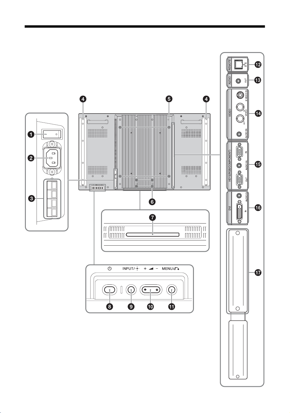
Rear
* The illustration only shows the FWD-S47H1.
GB
10
Page 57

Parts Description
1 Main power switch Turn the main power switch to “ON”(press the side) when setting up the device.
When the main power switch is turned “OFF” (press the side), the power consumption
is 0W.
2 AC I N socket Connect the supplied AC power cord to this socket and to a wall outlet. See page 19.
Once you connect the AC power cord and turn on main power switch, the
lights up in red and the display goes into the standby mode.
3 SPEAKER socket Connect the speakers SS-SPG01 (not supplied) to this socket. For more details on
connecting the speakers, see the operating manual that came with the speakers. For details
on how to route the speaker cords, see page 20.
4 Speaker installation
positions
5 Stand installation holes Screw holes conforming to VESA standard. (Pitch: 400mm × 400mm, Screw: M6)
6 Applicable display stand
installation holes
7 Dedicated display stand
installation hole cover
8 1 (POWER) switch Switches the display on or off (standby).
9 INPUT/
(ENTER)button
Attach the dedicated speakers SS-SPG01.
Use these hooks to install the display stand SU-S01 (not supplied).
Remove when mounting the display stand SU-S01 (not supplied).
Operate when the main power switch is “ON” ( side).
Press to select a signal to be input from the INPUT or OPTION connector.
The signal to be input switches as follows each time you press the INPUT button.
1 indicator
S Video Video HD15 DVI OPTION
When an optional adaptor supporting the video signal is not installed in the OPTION slot,
OPTION will be skipped.
Press to set your choice.
0 +/–/F/f (volume/cursor)
button
qa MENU/ (RETURN)
button
qs REMOTE
(10BASE-T/100BASE-TX)
Press to control speaker volume. When the menu is displayed, press to move the cursor or
set a value.
Press to set your choice.
Press to show menus.
This returns to the preceding menu screen.
Serves to connect the display to a network, using a 10BASE-T/100BASE-TX LAN cable.
You can assign various settings and control the display via the network from a PC.
GB
qd AUD IO
(Stereo mini jack)
Cautions
• When you connect the LAN cable of the unit to peripheral device, use the supplied cable to
prevent malfunction due to radiation noise.
• For safety, do not connect the connector for peripheral device wiring that might have
excessive voltage to this port. Follow the instructions for this port.
Note
When using this connector, select “Display” in “Network Port”. (page 32)
This is the audio monitor output terminal for external devices. Outputs an audio of the
signal currently indicated on the screen. Outputs an audio signal corresponding to the
active* picture while in the “P&P” or “PinP” mode.
Note
• Settings assigned in “Sound Mode” or “Speaker Out” will not be reflected.
• The noise reduction status set by the remote control is not reflected.
11
GB
Page 58

Parts Description
qf VIDEO S VIDEO IN (Mini DIN 4-pin): Connects to the S Video output of a piece of video
equipment.
VIDEO IN (BNC): Connects to the video output of a piece of video equipment.
VIDEO OUT (BNC): Connects to the video input of a piece of video equipment. Pictures
input from VIDEO IN will be output.
AUDIO IN (Stereo mini jack): Connects to the audio output of a piece of video
equipment.
qg HD15 (RGB/
COMPONENT)
(D-sub 15-pin)
qh DVI
(DVI-D 24-pin)
qj OPTION slot
(VIDEO/COM port)
* The status when the sound is output and the input signal can be switched.
HD15 (RGB/COMPONENT) IN: Connects to the analog RGB signal or component
signal output of a piece of video equipment or PC. See page 44.
AUDIO IN: Inputs an audio signal. Connects to the audio signal output of a piece of
video equipment or PC.
HD15 (RGB/COMPONENT) OUT: Connects to the analog RGB signal or component
signal input of a piece of video equipment or PC. See page 44. Signals input from the
HD15 (RGB/COMPONENT) IN connector above will be output.
Notes
• When inputting a component signal, be sure not to input sync signals to pins 13 and 14.
If you do so, the picture may not be displayed properly.
• When the display is not connected to an AC power or is in the standby mode, no signal
is output from the HD15 (RGB/COMPONENT) OUT.
DVI IN: Connects to the digital signal output terminal of the video equipment or PC.
Supports HDCP copy protection.
AUDIO IN: Inputs an audio signal. Connects to the audio signal output of a piece of
video equipment, etc.
This slot supports video signals and communication functions. Attach an optional adaptor
(the BKM-FW series) in this slot to extend monitor functions. See page 18.
12
GB
Page 59

Remote Control
Button Description
1 POWER ON switch
Press to turn the display on.
Operate when the main power switch on the backside of the display
is “ON.”
2 DVI button
Press to select the signal input to the DVI port.
3 S VIDEO button
Press to select the signal input to the S VIDEO IN connector from a
piece of video equipment.
4 VIDEO button
Press to select the signal input to the VIDEO IN connector from a
piece of video equipment.
5 PICTURE button
Selects “Picture Mode”. Each press toggles between “Vivid”,
“Standard”, “Custom”, “Conference”, and “TC Control”.
6 F/f/G/g/ buttons
The F/f/G/g buttons move the menu cursor and set values, etc.
Pressing sets the selected menu or setting items.
In the “PAP” mode, you can switch the Picture and Picture setting.
See page 16.
7 button
Press to change the aspect ratio. See page 15.
8 MENU button
Press to show menus. Press again to hide them. See page 21.
GB
Notes
• The 5 button and button have a tactile dot. Use the tactile dot as a reference when operating the display.
• Insert two size AA (R6) batteries (supplied) by matching the 3 and # on the batteries to the diagram inside the remote control’s
battery compartment.
Caution
Danger of explosion if battery is incorrectly replaced. Replace only with the same or equivalent type recommended by the
manufacturer. When you dispose of the battery, you must obey the law in the relative area or country.
Push and slide to open
,
13
GB
Page 60

9 ID MODE (ON/0-9/SET/C/OFF) buttons
You can operate a specific display without affecting other displays
installed at the same time.
• ON button:
• 0-9 button: Press to enter the “Index Number” of the display you want
to operate.
• SET button: Press to set the input “Index Number”.
• C button: Press to clear the input “Index Number”.
• OFF button: Press to return to the normal mode.
See page 17.
Press to show the “Index Number” on the screen.
0 +/– button
Adjusts the picture (contrast) level.
qa +/– button
Press to adjust the volume.
qs button
Press to mute the sound. Press again to restore sound.
qd button
Selects the “PAP” (Picture And Picture) mode. Each press toggles
between “P&P”, “PinP” and the single-screen picture. See page 16.
qf DISPLAY button
Press to display the currently selected input, the type of the input
signal and the “Aspect” setting on the screen. Press again to hide
them. If this displayed information is left undisturbed for a short time,
it will disappear automatically.
qg OPTION 1 button
When an optional adaptor is installed, selects an input signal from the
equipment connected to the optional adaptor.
If the installed optional adaptor has multiple input connectors, each
press of the button toggles between the input signals.
qh HD15 button
Press to select the input signal of the HD15 (RGB/COMPONENT)
connector. The RGB signal or component signal is selected
automatically or manually in accordance with the menu settings.
qj STANDBY button
Press to change the display to the standby mode.
Note
You cannot use the HDMI button and the OPTION 2 button on this display.
GB
14
Page 61

Special Buttons on the Remote Control
Using the Wide Mode
You can change the aspect ratio of the screen.
Tip
You can also access the “Aspect” settings in the “Screen”
settings. See page 28, 29.
For input from video equipment such as Video, DVD,
etc. (other than PC input)
4:3 Original Source
16:9 Original source
Wide Zoom
Zoom
Full
4:3
m
GB
Wide
Zoom
Zoom
Full
4:3
m
For PC Input
Illustrations below indicate the input resolution of
800×600
Real
Full 1
Full 2
Note
If the input resolution is higher than the panel resolution
(1,920
× 1,080), the display of Real is the same as Full 1.
15
GB
Page 62

Using the PAP Setting
You can show two pictures from different signal sources, such as a PC and a video, side by side.
You can also swap the active pictures, or change the balance of picture sizes.
You can also access the “PAP Setting” in the “Screen” settings. See page 26.
Cursor showing active picture
For P&P
The width of A and B is
the same.
The height will be set to
match each picture’s
aspect ratio.
The width of A and B is the
same.
The height will be set to
match each picture’s
aspect ratio.
For PinP
Press G button.
The width of A is larger
than that of B.
If A’s aspect ratio is
4:3, its height will be
equal to the panel size.
Press g button.
B on the right side
becomes the active
picture.
Press g button.
The inset picture (B) is
shown within the main
picture (A).
Press G/g button.
The inset picture (B)
becomes the active
picture.
Press g button.
The width of B is larger
than that of A.
If B’s aspect ratio is 4:3,
its height will be equal to
the panel size.
Press f button.
B on the right side
becomes small while
remaining the active
picture.
The size of the inset picture
(B) will become large.
Press f button.
The size of the inset picture
(B) will become small.
Press button.
The position of the
inset picture (B) will
change.
Press F button.
Tips
• The cursor indicating the active picture will disappear after 5 seconds.
• The picture can be adjusted to 15 sizes. (For P&P)
GB
16
Page 63

Using the ID MODE button
You can operate a specific display without affecting
other displays installed at the same time.
1 Press ON button.
Display’s “Index Number” appears in black
characters on the lower left menu on the screen.
(Every display is allocated an individual preset
“Index Number” from 1 to 255.)
Index Number
Index Number : 117
2 Input the “Index Number” of the display you
want to operate using the 0 - 9 buttons on
the remote control.
The input number appears right next to the “Index
Number” of each display.
4 When all of the setting changes have been
completed, press OFF button.
The display returns to the normal screen.
To correct the Index Number
Press the C button to clear the current input “Index
Number”. Return to Step 2, and input a new “Index
Number”.
Tip
To change the “Index Number” of the display, see “Index
Number” in “Control Setting” on page 30.
GB
Input Number
Index Number : 117
117
3 Press SET button.
The characters on the selected display change to
green while the others change to red.
You can operate the specified display indicated
with green characters only.
Only the operation of POWER ON switch and
STANDBY/ID MODE-OFF button is effective to
other displays, as well.
17
GB
Page 64

Optional Adaptors
The terminal of the OPTION slot qj (page 12) on the
side of the equipment is a slot-in type. It can be
switched to the following optional adapter (not
supplied).
For details on installation, consult your Sony dealers.
For details on the optional adaptors for system
expansion, see each instruction manual with this
manual.
COMPONENT/RGB INPUT Adaptor BKMFW11
1 Y/G, PB/CB/B, PR/CR/R IN (BNC): Connects to
the analog RGB signal or component signal output
of a piece of video equipment or PC.
2 HD, VD IN (BNC): Connects to the
synchronization signal output of a PC.
Note
When inputting a component signal, be sure not to input sync
signals to the HD and VD connectors. If you do so, the
picture may not be displayed properly.
3 AUDIO (Stereo mini jack): Inputs an audio
signal. Connects to the audio output of a piece of
video equipment or PC.
HDMI INPUT Adaptor BKM-FW15
HD-SDI/SDI INPUT Adaptor BKM-FW16
Connects to the HD-SDI signal output of a piece of
video equipment.
MONITOR CONTROL Adaptor BKM-FW21
1 CONTROL S IN/OUT (Mini jack): You can
control pieces of multiple equipment with a single
remote control when the display is connected to
the CONTROL S connector of the video
equipment or another display. Connect the
CONTROL S OUT connector on this adaptor to
the CONTROL S IN connector of the other
equipment, and connect the CONTROL S IN
connector on this adaptor to the CONTROL S
OUT connector of the other equipment.
2 REMOTE (D-sub 9-pin): This connector allows
remote control of the display using the RS-232C
protocol. For details, contact your authorized
Sony dealers.
Notes
• The REMOTE connector and the REMOTE (LAN)
connector qs (page 11) on the side of the equipment
cannot be used at the same time.
• When using the REMOTE connector, select “Option” in
“Network Port”. (page 32)
You can enjoy enhanced or high-definition video, and
two-channel digital audio.
The appropriate mode for a piece of audio/video
equipment or PC is automatically selected in
accordance with the connected equipment.
Note
Be sure to use only an HDMI cable (not supplied) that bears
the HDMI logo.
GB
18
STREAMING RECEIVER Adaptor BKM-FW50
This adaptor enables you to use this display for digital
signage.
You can easily play back movies, still images or
background music in designated data formats by just
inserting a recording media. You can also use a
network to view images from a remote computer on
the display.
Note
A compact flash memory card is required.
Page 65

Connections
Before you start
• First make sure that the power of each piece of equipment
is turned off.
• Use cables suitable for the equipment to be connected.
• Connect the cables, fully inserting them into the
connectors or jacks. A loose connection may cause hum
and other noise.
• To disconnect the cable, pull it out by grasping the plug.
Never pull the cable itself.
• See the instruction manual of the equipment to be
connected, too.
• Insert the plug securely into the AC IN socket.
• Use one of the two AC plug holders (supplied) to securely
hold the AC plug.
Connecting the
Connecting the AC
Power Cord
1 Plug the AC power cord into the AC IN
socket. Then, attach the AC plug holder
(supplied) to the AC power cord.
Speakers
Connect the speakers SS-SPG01 (not supplied).
Please be sure to connect the speakers correctly. For
more details on connecting the speakers, see the
operating manual of the speakers. For details on how
to route the speaker cords, see page 20.
GB
AC power cord
AC IN socket
AC plug holder
2 Slide the AC plug holder over the cord until
it connects to the AC IN socket cover.
AC IN socket cover
To remove the AC power cord
After squeezing the AC plug holder and freeing it,
grasp the plug and pull out the AC power cord.
19
GB
Page 66

Cable Management
Using the cable holders
You can neatly bundle the cables with the cable holders (×9) provided. Attach the cable holders as shown in the
illustrations below.
Rear
321
20
GB
Page 67

Using the Settings
Overview of the Menus
1 Press MENU button.
2 Press F/f to highlight the desired menu
icon.
3 Press or g.
To exit the menu, press MENU button.
2,3
1
The settings provide you access to the following features:
Settings Allows you to set/change
Picture/Sound
DVI
Screen
DVI
Picture Mode: (page 22, 24)
Picture Mode Adjust. (page 22, 24)
Sound Mode: (page 23, 25)
Sound Mode Adjust. (page 23, 25)
Note
You cannot set or change
is no signal input.
PAP Setting (page 26, 29)
Multi Display (page 27, 29)
Aspect: (page 28, 29)
Adjust Screen (page 28, 29)
To change the on-screen language
Select the desired language for on-screen settings and
messages from “English”, “Français”, “Deutsch”,
“Español”, “Italiano” or “ ”.
“English” (English) is set for the default setting.
See page 30.
“Picture Mode” or “Picture Mode Adjust.” when there
GB
Setup
DVI
* Menu icons displayed at the bottom of the screen may not work, depending on the settings.
Language: (page 30)
Timer Setting (page 30)
ECO Mode: (page 30)
Status Display: (page 30)
Speaker Out: (page 30)
Advanced Setup (page 30)
Information (page 33)
All Reset (page 33)
21
GB
Page 68

Picture/Sound Settings
For Video Input
VIDEO
To highlight an option and to change settings, press
F/f/G/g.
Press to confirm the selection.
The “Picture/Sound” settings include the following
options:
Picture Mode
Picture Mode Adjust.
“Vivid”: Select for enhanced picture contrast and sharpness.
“Standard”: Select for standard picture settings.
“Custom”: Allows you to store preferred settings.
“Conference”: Adjusts the picture quality for video conferencing under fluorescent
lights.
“TC Control”: The setting is common with “Vivid”. In addition, you can use the
“True Color Control” function (after-mentioned).
Tip
To change from one “Picture Mode” option to another, you can also use PICTURE on the
remote control instead.
Notes
• “Conference” may not be effective depending on the environment or the video conference
system under use. In this case, adjust the picture quality, switch to other settings of “Picture
Mode”, etc.
• In “TC Control”, “Brightness Boost” is fixed to Off.
“Backlight”: Adjusts to brighten or darken the screen.
“Contrast”: Adjusts picture contrast.
“Brightness”: Adjusts to brighten or darken the picture.
“Chroma”: Adjusts to increase or decrease color intensity.
“Phase”: Adjusts the color tones of the picture.
“Sharpness”: Adjusts to sharpen or soften the picture.
“Noise Reduction”: Select to reduce the noise level of connected equipment. Select
from “Off”, “Low”, “Mid”, “High” to set the noise level.
“CineMotion”: Select “Auto” to optimize the screen display automatically
detecting film content and applying a reverse 3-2 pull down or 2-2 pull down
process. Moving picture will appear clearer and more natural looking. Select “Off”
to disable the detection.
“Dynamic Picture”: Select “On” to enhance contrast by making white brighter and
black darker.
“Gamma Correct.”: Balances the light and dark portions of pictures. Select from
“High”, “Mid”, “Low” to make settings.
22
Notes
• “Option” can only be set when there is a DVI input.
• Gamma setting is in accordance with the Grayscale Standard Display Function (GSDF) of
the Digital Imaging and Communications in Medicine (DICOM) standards. However, this
setting is for reference only and cannot be used for medical diagnosis.
“Color Temp.”:White tone can be adjusted to suit your preference. The factory
default settings are adjusted to color temperature.
“Cool”: Select to give the white colors a blue tint.
“Neutral”: Select to give the white colors a neutral tint.
“Warm”: Select to give the white colors a red tint.
“Custom”: Enables a broader range of white tone to be set than above.
GB
Page 69

Tip
Restores the default settings by selecting “Reset” on the tone adjusting screen.
“Brightness Boost”: Emphasizes the brightness of the image.
Notes
• When “Brightness Boost” is set to “On”, you cannot adjust the “Backlight”, “Contrast”,
“Brightness” or “Color Temp.” settings.
• When “Brightness Boost” is set to “On” and “ECO Mode” is switched “Off”, the brightness
is at its maximum.
“True Color Control”: You can adjust the details of hue and saturation for each of
4 colors : red, green, yellow, blue, and you can highlight specific colors in the image.
Select the color which you want to adjust, and you can check and see which part of
current image will be adjusted. Then you can adjust it using the matrix dialog.
Notes
• This option can be adjusted when “Picture Mode” is set to “TC Control”.
• In “PAP” mode, you cannot select this option. Even if you select this option in the singlepicture screen, the setting of this option may not be applied in the “PAP” mode
“Reset”: Resets all settings of “Picture Mode Adjust.” to default settings.
Notes
• “Phase” is not available when the input is Video or S Video and the color system of video
signal is not NTSC.
• “Dynamic Picture” is not available when “Picture Mode” is set to “Conference” or “TC
Control.”
• You can make settings and adjustments for each “Picture Mode” but “Backlight,” “Noise
Reduction” and “CineMotion” settings are common for all “Picture Mode.”
• “Dynamic Picture” and “CineMotion” do not function in PAP mode.
Sound Mode
You can adjust the sound output from the speakers SS-SPG01 (not supplied) with
various “Sound Mode” settings.
“Dynamic”: Select to enhance treble and bass.
“Standard”: Flat setting.
“Custom”: Allows you to store preferred settings.
Sound Mode Adjust.
“Treble”: Adjusts to increase or decrease higher-pitched sounds.
“Bass”: Adjusts to increase or decrease lower-pitched sounds.
“Balance”: Adjusts to emphasize left or right speaker balance.
“Surround”: Select the surround mode according to the type of picture.
“Off”: No surround output.
“Hall”: When desiring to give the stereo sound of movies or music programs a
greater sense of presence.
“Simul.”: When desiring to give ordinary monaural programs or news telecasts
an enhanced sense of presence using simulated stereo sound.
“Reset”: Resets all settings of “Sound Mode Adjust.” to default settings.
Tips
• You can alter the “Picture Mode Adjust.” settings (“Contrast”, “Brightness”, “Chroma ”, etc.) for each “Picture Mode”.
• You can adjust the “Sound Mode Adjust.” settings (“Treble” and “Bass”) when the “Sound Mode” is set to “Custom”.
GB
Note
In the “PAP” mode, only “Picture/Sound” settings for the active picture can be adjusted.
23
GB
Page 70

For PC Input
When input is switched to a PC input source, the
“Picture/Sound” settings specific to PC input are
applied.
The “Picture/Sound” settings for a PC include the
following options:
Picture Mode
Picture Mode Adjust.
“Vivid”: Select for enhanced picture contrast and sharpness.
“Standard”: Select for standard picture settings.
“Custom”: Allows you to store preferred settings.
“Conference”: Adjusts the picture quality for video conferencing under fluorescent
lights.
“TC Control”: The setting is common with “Vivid”. In addition, you can use the
“True Color Control” function (after-mentioned).
Tip
To change from one “Picture Mode” option to another, you can also use PICTURE on the
remote control instead.
Notes
• “Conference” may not be effective depending on the environment or the video conference
system under use. In this case, adjust the picture quality, switch to other settings of “Picture
Mode”, etc.
• In “TC Control”, “Brightness Boost” is fixed to Off.
“Backlight”: Adjusts to brighten or darken the screen.
“Contrast”: Adjusts picture contrast.
“Brightness”: Adjusts to brighten or darken the picture.
“Gamma Correct.”: Balances the light and dark portions of pictures. Select from
“High”, “Mid”, “Low” to make settings.
Notes
• “Option”can only be set when there is a DVI input.
• Gamma setting is in accordance with the Grayscale Standard Display Function (GSDF) of
the Digital Imaging and Communications in Medicine (DICOM) standards. However, this
setting is for reference only and cannot be used for medical diagnosis.
“Color Temp.”: White tone can be adjusted to suit your preference. The factory
default settings are adjusted to color temperature.
“Cool”: Select to give the white colors a blue tint.
“Neutral”: Select to give the white colors a neutral tint.
“Warm”: Select to give the white colors a red tint.
“Custom”: Enables a broader range of white tone to be set than above.
Tip
Restores the default settings by selecting “Reset” on the tone adjusting screen.
“Brightness Boost”: Emphasizes the brightness of the image.
Notes
• When “Brightness Boost” is set to “On”, you cannot adjust the “Backlight”, “Contrast”,
“Brightness” or “Color Temp.” settings.
• When “Brightness Boost” is set to “On” and “ECO Mode” is switched “Off”, the brightness
is at its maximum.
“True Color Control”: You can adjust the details of hue and saturation for each of
4 colors : red, green, yellow, blue, and you can highlight specific colors in the image.
Select the color which you want to adjust, and you can check and see which part of
current image will be adjusted. Then you can adjust it using the matrix dialog.
24
GB
Page 71

Notes
• This option can be adjusted when “Picture Mode” is set to “TC Control”.
• In “PAP” mode, you cannot select this option. Even if you select this option in the singlepicture screen, the setting of this option may not be applied in the “PAP” mode
“Reset”: Resets all settings of “Picture Mode Adjust.” to default settings.
Note
You can make settings and adjustments for each “Picture Mode” but “Backlight” is common
for all “Picture Mode.”
Sound Mode
You can adjust the sound output from the speakers SS-SPG01 (not supplied) with
various “Sound Mode” settings.
“Dynamic”: Select to enhance treble and bass.
“Standard”: Flat setting.
“Custom”: Allows you to store preferred settings.
Sound Mode Adjust.
“Treble”: Adjusts to increase or decrease higher-pitched sounds.
“Bass”: Adjusts to increase or decrease lower-pitched sounds.
“Balance”: Adjusts to emphasize left or right speaker balance.
“Surround”: Select the surround mode according to the type of picture.
“Off”: No surround output.
“Hall”: When desiring to give the stereo sound of movies or music programs a
greater sense of presence.
“Simul.”: When desiring to give ordinary monaural programs or news telecasts
an enhanced sense of presence using simulated stereo sound.
“Reset”: Resets all settings of “Sound Mode Adjust.” to default settings.
Tips
• You can alter the “Picture Mode Adjust.” settings (“Contrast”, “Brightness”, “Chroma ”, etc.) for each “Picture Mode”.
• You can adjust the “Sound Mode Adjust.” settings (“Treble” and “Bass”) when the “Sound Mode” is set to “Custom”.
Notes
• “Chroma”, “Phase”, “Sharpness”, “Noise Reduction”, “CineMotion”, and “Dynamic Picture” are not available for PC input.
• In the “PAP” mode, only “Picture/Sound” settings for the active picture can be adjusted.
GB
25
GB
Page 72

Screen Settings
For Video Input
VIDEO
To highlight an option and to change settings, press
F/f/G/g.
Press to confirm the selection.
The “Screen” settings include the following options:
PAP Setting
Allows you to show two pictures from different signal sources, such as a PC and a
video, side by side.
“PAP”
“Off”: Disables “PAP” function.
“P&P”: Shows two pictures side by side at the same time.
“PinP”: Displays two pictures as the inset picture within the main picture.
For P&P
“Active Picture”: Selects the screen to operate.
“Left”: You can activate the left picture to operate it.
“Right”: You can activate the right picture to operate it.
“Swap”: Swaps the two pictures side by side.
“Picture Size”: Adjusts the balance between two pictures side by side. Adjust the
balance by pressing G or g button, and then press button to set the adjustment.
(page 16)
For PinP
“Active Picture”: Selects the screen to operate.
“Main”: You can activate the main picture to operate it.
“Sub”: You can activate the inset picture to operate it.
“Swap”: Swaps the main and the inset pictures.
“Picture Size”: Adjusts the size of the inset picture. Select from “Large” or “Small”.
“Picture Position”: Adjusts the position of the inset picture with F/f/G/g, then
press .
Tip
You cannot change the aspect ratio in the “PAP” mode. The picture is displayed in the last
aspect ratio used prior to selecting “PAP” mode.
Available combination of two pictures
RGB/YUV
S Video Video
S Video
Video
RGB/YUV
DVI aaaa
1) Supported when “Display” is set to “YUV” or when “Option” is set to “RGB” in “RGB/YUV”.
2) Supported when “Display” is set to “RGB” or when “Option” is set to “YUV” in “RGB/YUV”.
Tip
Output from BKM-FW50 is considered as RGB output shown in the table in the “PAP” mode.
RGB aa a a
Component aa
Component
RGB
aaaaaaa
aaaaaaa
DVI
a a
RGB
1)
aa
Component
OPTION
HDMI
2)
HD-SDI/
SDI
aa
aa
26
GB
Page 73

Multi Display
Allows you to make settings for connecting multiple displays to form a video wall.
“Multi Display”
“Off”: Uses a single screen.
“2×2”/“3×3”/“4×4”: Sets to connect multiple displays such as 2, 3 or 4 displays
both vertically and horizontally.
“1×2”/“1×3”/“1×4”: Sets to connect multiple displays such as 2, 3 or 4 displays
horizontally.
“2×1”/“3×1”/“4×1”: Sets to connect multiple displays such as 2, 3 or 4 displays
vertically.
“Position”: Select the position of each display in the arrangement of the video wall
with F/f/G/g. Press to set the position.
“Output Format”: Selection of two picture output formats will be available as
shown in the figures. By simply selecting either format, suitable picture output will
be available without manually adjusting the horizontal and vertical shift. Select
either “Tiles” or “Window”.
“Tiles”
Just scan
“Window”
Over scan
GB
To show full signal on
each display.
To show one large picture with
multi display naturally.
Part of the signal will go behind
the bezel area.
“LED”: “On” makes the 1 indicator on the front panel (page 9) to be continually
turned on, and “Off” makes the 1 indicator on the front panel to be continually
turned off.
Notes
• “Multi Display” can display an enlarged picture keeping the current “Aspect” setting as
much as possible for video input, and can display an enlarged picture of which “Aspect” is
set to “Full 2” for PC input.
• You can set the “Multi Display” only when the “PAP” function is disabled.
• When “Position” is set to the right-bottom, the
“Off”. The indicator also lights up even when the display is off (standby), errors are detected,
or the display is in sleep mode including the case of no signal or unsupported signal.
1 indicator lights up even if “LED” is set to
27
GB
Page 74

Aspect
“Wide Zoom”: Select to enlarge to fill screen with minimum distortion.
“Zoom”: Select to enlarge the original picture without distorting the aspect ratio.
See page 15.
“Full”: Select to enlarge the original picture horizontally to fill the screen when the
original source is 4:3 (Standard definition source). When the original source is 16:9
(High definition source), select this mode to display 16:9 picture in original size.
“4:3”: Select to display all the pictures in original size to 4:3 aspect ratio..
Tips
• To change from one “Aspect” option to another, you can also use on the remote control.
• Select “Zoom” to display movies and other DVD content with black bands, using the entire
viewable area of the screen.
Note
You cannot set the “Aspect” while using the “PAP” function or the “Multi Display”.
Adjust Screen
“H Size”: Allows you to adjust the size of the picture horizontally. Press G/g and
press to choose a correction.
“H Shift”: Allows you to move the position of the picture left and right in the
window. Press G/g and press to choose a correction.
“V Size”: Allows you to adjust the size of the picture vertically. Press F/f and press
to choose a correction.
“V Shift”: Allows you to move the position of the picture up and down in the
window. Press F/f and press to choose a correction.
“Reset”: Resets all settings of “Adjust Screen” to default settings.
Notes
• “Adjust Screen” is not available while using the “PAP” function.
• If there is no signal currently being input, none of the “Screen” settings options, except for “PAP Setting” and “Multi Display”
can be selected.
28
GB
Page 75

For PC Input
When input is switched to PC input source, the
“Screen” settings specific for PC input are applied.
The “Screen” settings for a PC include the following
options:
PAP Setting
Multi Display
Aspect
Adjust Screen
See “PAP Setting” for video input (page 26).
See “Multi Display” for video input (page 27).
“Full 1”: Select to enlarge the picture to fill the display area in the vertical direction,
keeping its original horizontal-to-vertical aspect ratio. A black frame will appear on
the surrounding of the picture.
“Full 2”: Select to enlarge the picture to fill the display area.
“Real”: Select to display the picture in its original number of dots.
Notes
• You cannot set the “Aspect” while using the “PAP” function or the “Multi Display”
function.
• If the input resolution is higher than the panel resolution (1,920 × 1,080), the display of
“Real” is the same as “Full 1”.
“Auto Adjustment”: Select “OK” to automatically adjust the display position and
phase of the picture when the display receives an input signal from the connected PC.
Note that “Auto Adjustment” may not work well with certain input signals. In such
cases, manually adjust the options below.
“Phase”: Select to adjust the phase when the screen flickers.
“Pitch”: Select to adjust the pitch when the picture has unwanted vertical stripes.
Tip
“Auto Adjustment,” “Phase,” “Pitch” are not available when digital signal such as DVI is input.
“H Size”: Allows you to adjust the size of the picture horizontally. Press G/g and
press to choose a correction.
“H Shift”: Allows you to move the position of the picture left and right in the
window. Press G/g and press to choose a correction.
“V Size”: Allows you to adjust the size of the picture vertically. Press F/f and press
to choose a correction.
“V Shift”: Allows you to move the position of the picture up and down in the
window. Press F/f and press to choose a correction.
“Reset”: Resets all settings of “Adjust Screen” to default settings.
GB
Note
If there is no signal currently being input, none of the “Screen” settings options, except for “PAP Setting” and “Multi Display” can
be selected.
29
GB
Page 76

Setup Settings
Language
Timer Setting
ECO Mode
Status Display
Speaker Out
Advanced Setup
DVI
Select to display all on-screen settings in your language of choice: “English”,
“Français”, “Deutsch”, “Español”, “Italiano” or “ ”.
You can adjust time, display the built-in clock, or set the timer to make the display
power on/off at a predetermined time.
“Clock Set”: Sets the day of the week and the hour of the day.
“Date Set”: Sets the date (year, month, date). The day is automatically set.
“Time Set”: Sets the time.
“Clock Display”: Displays the currently set time on the screen when set to “On,” by
pressing the display button on the remote control.
“On/Off Timer”: Sets the day of the week and the hour of the day.
Note
If the built-in clock tends to lose time, the internal battery may be exhausted. Please
contact your authorized Sony dealer to have the battery replaced.
“Off”: Select to view picture without the benefit of power saving.
“Low”/“High”: Select to change brightness and reduce power consumption.
“On” makes input signal and “Aspect” information appear on the screen for about 5
seconds when the display is turned on, and the input signal information appear for
about 5 seconds when the input signal is switched, while “Off” disables display of
status information.
Tip
You can display the input signal and “Aspect” information by using DISPLAY on the remote
control regardless of the “Status Display” setting.
“On”: Enables sound to be emitted from the speakers.
“Off”: Disables sound to be emitted from the speakers.
“Control Setting”: This menu is used for settings of operation of the display and the
remote control.
“Index Number”: You can change the index number of the display if necessary.
Select to set the index number of the display with F/f and press (ENTER) to
confirm the setting.
Note
When you set the “Index Number”, use the buttons on the display. The “Index Number”
cannot be set with the remote control.
“Control Mode”
“Display+Remote”: You can operate the display with the control buttons on
the display and the remote control.
“Display Only”: Disables the remote control function. You can make
settings for the display only using the control buttons on the display.
“Remote Only”: Disables the controls on the display. You can make
settings for the display only using the remote control.
To highlight an option and to change settings, press
F/f/G/g.
Press to confirm the selection.
The “Setup” settings include the following options:
30
GB
Page 77

Note
When this item is operated, the available modes will differ depending on whether you
select by the remote control or the display. When setting this item with on the remote
control, you can select only “Display+Remote” or “Remote Only”. When setting this
item with
“Display Only”.
(ENTER) on the display, you can select only “Display+Remote” or
“Auto Screen Adjust”
“On”: The settings such as picture size and position are saved for each input
signal, and the last settings are automatically applied each time the input signals
are switched.
“Off”: The “Auto Screen Adjust” is disabled even when input signals are
switched and the default settings are applied.
“Auto Shut Off”:
“On”: The display automatically enters the standby mode when a signal is not
input to the Video or S Video input connectors for more than about 5 minutes.
The display automatically enters the power saving mode when a signal is not
input to the DVI or HD15 (RGB/Component) input connectors for more than
about 30 seconds.
“Off”: The display is not turned off automatically even when no signal is input
to any connector.
Tips
• While in the standby mode, press the 1 (POWER) switch on the display or the POWER
ON switch on the remote control to turn the display on. In the power saving mode, the
display is turned on automatically when a signal is input.
• This function is not available when “On-Screen Logo” is set to “On”, the screensaver
function is activated, or PAP is selected.
“Overscan”: Selects whether to display images with overscan or underscan.
“Auto”: Switches automatically signal image which are supposed to be DTV to
image with overscan.
“On”: Displays image with overscan.
“Off”: Displays image with underscan.
Note
If “Overscan” is set to “Off,” DTV signal image may be displayed like PC signal display.
Example: 480P t 720 × 480/60
“Sync Mode”: Sets the mode according to the signal input at pin 13 of the HD15
(RGB/COMPONENT) IN connector.
“H/Comp”: Select when a horizontal synchronous signal or a composite
synchronous signal is input.
“Video”: Select when a video signal is input.
Notes
• “Sync Mode” is available only when analog RGB signal is input to HD15 connector.
• Depending on the level of the composite synchronous signal, the image may not be displayed
correctly. In this case, change the “Sync Mode” setting.
• There are some inputs for which only synchronizing signals can be selected. In this case,
input horizontal/vertical synchronization signals through the pin 13 or 14 of the connectors.
• Sync Mode settings cannot be carried out for the input through the optional adaptors.
• This display does not support the three value sync format of 576/60p.
• When “Video” is selected in “Sync Mode”, you can only set the 575/50i and 480/60i signals.
• When you select the video signal for the synchronous mode setting, you cannot use the PAP
function.
GB
31
GB
Page 78

“RGB/YUV”
“Display”/“Option”: Sets the type of signal for a video device or PC connected
to the HD15 (RGB/COMPONENT) terminal of the display or the 5BNC (RGB/
COMPONENT) terminal of an optional adaptor.
“Auto”: Select to choose either an analog RGB input signal or a component
input signal from a connected equipment.
“RGB”: Select to choose an analog RGB input signal from a connected
equipment.
“YUV”: Select to choose a component input signal from a connected
equipment.
Note
Select “RGB” to input RGB signals using a composite synchronous signal.
Tip
For the available combination of two pictures, see page 26.
“Color System”: Select the color system of video signals from “Auto”, “NTSC”,
“NTSC4.43”, “PAL”, “PAL-M”, “PAL-N” or “PAL60”. Select “Auto” to set the
color system automatically.
Note
“Color System” is not available for PC input.
“Screen Saver”: This is a setting to prevent or reduce screen burn or after-image
that can occur by long periods of screen display of the same image.
“All White”: Displays an all white screen. (Stops automatically after about 30
minutes and the display enters standby mode.)
“Sweep”: Scrolls a white bar over the screen.
“Standby”: The screensaver operates in standby (page 9) for the time specified
in “Timer Setting.” (The display is blank during screensaver operation.) When
the screensaver ends, normal standby mode is resumed.
“Logo”: The Sony logo on the front of the unit lights.
“Position”: The logo can be constantly lit at the bottom side of the screen by
setting the setup method of the equipment from “Auto,” “Landscape,” and
“Portrait.” If “Auto” is selected, Landscape or Portrait will automatically be
selected.
“Illumination”: Select “Off” to have the logo extinguished. Select “Low” and
“High” for the brightness.
“On-Screen Logo”
“On”: The model name logo is displayed when the signal is not inputted.
“Off”: The model name logo is not displayed when the signal is not inputted.
“Network Port”: Sets the network port to operate the display by remote control.
“Off”: Select when not using the network port. The power consumption during
standby mode can be reduced.
“Display”: Allows you to make settings of the display from a PC connected to
the REMOTE (LAN) connector of the display. (page 36)
“Option”: Allows you to make settings of the display from a PC connected to
the REMOTE connector or the LAN connector of the OPTION slot. (page 36)
“IP Address Setup”: Sets an IP address to enable communication speed between
the REMOTE (LAN) connector of the display or the optional adaptor and the
equipment such as a PC connected with the LAN cable.
“Speed Setup”: Sets a communication speed between the REMOTE (LAN)
connector of the display or the optional adaptor and the equipment such as a PC
connected with the LAN cable.
“Power On Delay”: Adjusts the time until power-on. Sets to Off, and 1 to 120
seconds. This suppresses a sudden load fluctuation to the power equipment when
multiple units are connected.
Tip
For details on how to make the settings of “IP Address Setup” and “Speed Setup”, see the
section of “Preparations for Using the Network Functions” (page 34).
32
GB
Page 79

Information
All Reset
Displays the “Date”, “Model Name”, “Serial Number”, “Operation Time”,
“Software Version” and “IP Address” of your display. When the optional adapter
BKM-FW50 is mounted, “Player IP Address” (IP address for still image and movie
playback function) is displayed. For details, see the instruction manual of the BKMFW50.
Resets all adjustments and settings to factory settings.
Note
The items included in the “Information” option and the “Index Number” will not be
reset.
GB
33
GB
Page 80

Network Functions
Preparations for Using
the Network Functions
Precautions
• The software specifications of this display are
subject to change for improvements without notice.
• Screens shown by application software may differ
slightly from the illustrations shown in this manual.
• For safety, connect the port of this display only to a
network where there is no danger of excessive
voltage or voltage surges.
• The steps described in this manual are guaranteed
only for use under the following environment
conditions.
Operating system:
Microsoft Windows XP/Windows Vista
Browser:
Microsoft Internet Explorer 6.0 or later
• To ensure security on the network, setting a user
name and password is recommended. For
information on how to make these settings, see the
section “Setup screen” (page 37).
For security settings, refer to your network
administrator.
Setting an IP address
The display can be connected to a network with
10BASE-T/100BASE-TX LAN cable.
When connected to a LAN, the IP addresses of the
display can be set using one of the following two
methods. Consult your network administrator
regarding details about IP address selection.
• Assigning a fixed IP address to the display
Normally this method should be used. Note that in
factory setting, the display is set to obtain an IP
address automatically.
• Automatically obtaining an IP address
If the network to which the display is connected has
a DHCP server, you can have the DHCP server
automatically assign an IP address. Note that in this
case the IP address may change every time the
display in which the display is installed is turned on.
Before setting the IP address, connect the LAN cable
to the display to establish the network. After about 30
seconds, turn on the display, and then start making the
desired settings.
• Microsoft and Windows are registered trademarks of Microsoft Corporation in the United States of America and/
or other countries.
• All other product names, company names, etc. mentioned in this manual are trademarks or registered trademarks
of their respective owners.
GB
34
Page 81

Assigning a fixed IP address to the display
1 Press MENU to bring up the main menu.
2 Select “Setup” with F/f and press .
3 Select “Advanced Setup” with F/f and
press .
4 Select “IP Address Setup” with F/f and
press .
5 Select “Manual” with F/f and press .
Note
When an IP address is not set properly, the following error
codes will be displayed in accordance with the error cause.
Error 1: Communication error between the display and the
optional adaptor such as the BKM-FW50
Error 2: The specified IP address is already used for other
equipment
Error 3: IP address error
Error 4: Gateway address error
Error 5: Primary DNS address error
Error 6: Secondary DNS address error
Error 7: Subnet mask error
6 Select an desired item to set from “IP
Address”, “Subnet Mask”, “Default
Gateway”, “Primary DNS”, “Secondary
DNS” with F/f and press .
7 Set the three digit value (0 to 255) for each
of the four box with F/f on the display or
numeric keys on the remote control and
press or g.
8 Set the three digit value (0 to 255) for each
of the four boxes and press . Repeat the
same procedure as step 6 and select the
next desired item to set with F/f and press
.
9 After values are set for all the desired
items, select “Execute” with F/f, then
press .
Select “Execute” and press . An IP address is set
manually.
When “Cancel” is selected, the setting will return to
the original setting.
Automatically obtaining an IP address
1 Press MENU to bring up the main menu.
2 Select “Setup” with F/f and press .
3 Select “Advanced Setup” with F/f and
press .
4 Select “IP Address Setup” with F/f and
press .
5 Select “DHCP” with F/f and press .
Select “Execute” and press . An IP address is
automatically set.
When “Cancel” is selected, the setting will not be
executed.
Checking the automatically assigned IP
address
1 Press MENU to bring up the main menu.
2 Select “Setup” with F/f and press .
3 Select “Information” with F/f and press
.
4 Select “IP Address” with F/f and press
.
The IP address currently acquired is displayed.
Tip
When an IP address cannot be acquired properly, the
previously acquired IP address is shown in “Information”
and in “Manual” of “IP Address Setup”.
Setting a communication speed
1 Press MENU to bring up the main menu.
2 Select “Setup” with F/f and press .
3 Select “Advanced Setup” with F/f and
press .
4 Select “Speed Setup” with F/f and press
.
5 Select a desired communication speed to
set from “Auto”, “10Mbps Half”, “10Mbps
Full”, “100Mbps Half”, or “100Mbps Full”
with F/f and press .
When “Auto” is selected, a communication speed
appropriate for your network configuration is
automatically set.
6 Select “Execute” with F/f and press to
reflect the setting.
GB
35
GB
Page 82

PC Operation
Setting items on respective screens
When using the LAN function of the display
Controlling the display
You can make various display settings on the screen
of the PC.
Make sure that the display, PC, and router or hub are
properly connected with the network cable. Then turn
on power to the display, the PC, and the router or hub.
There are four display screens, divided by function:
Information screen, Configure screen, Control screen,
and Setup screen.
For details on the functions of buttons, see instructions for
each function of the display.
1 Start the browser of the PC (Internet
Explorer 6.0 or later).
2 Enter the IP address that was assigned to
the display in the previous page as
“http://xxx.xxx.xxx.xxx”, then press the
ENTER key on the keyboard.
When a user name and password have
been set, the “Network Password” screen
appears. Enter the user name and
password that were set, and then proceed
to the next step.
3 Click the function tab at the top of the
screen and select the desired screen.
Information screen
This screen shows the model name, serial number and
other display information, as well as the power status
and the input signal selection.
The screen is for information only. There are no items
that can be set.
Configure screen
Timer
Lets you make settings for the timer function.
Click “Apply” when done.
Screen Saver
Lets you make settings for the screensaver function.
Click “Apply” when done.
Picture and Picture
Lets you make settings for the Picture and Picture
function.
Click “Apply” when done.
Note
Before setting the “Timer” function, make sure to configure
the time setting on the Setup screen (page 37).
Control screen
POWER
Switches the display on or off.
36
INPUT
Lets you select the input signal.
PICTURE MODE
Lets you select the picture mode.
ASPECT
Lets you switch the aspect ratio of the image.
Volume +/– buttons
Adjust the display volume.
Contrast +/– buttons
Adjust the screen contrast.
Brightness +/– buttons
Adjust the picture brightness.
Chroma +/– buttons
Adjust the color intensity.
GB
Page 83

Phase +/– buttons
Adjust the color balance.
Reset button
Resets the settings from “Contrast” to “Phase” to their
factory default values.
Notes
• If the input signal is Video or S Video and the color system
of the video signal is not NTSC, “Phase” is not available.
• “Chroma” and “Phase” are not available for PC input.
• “Normal” at the ASPECT setting corresponds to “4:3” for
video input or “Real” for PC input.
Setup screen
This screen lets you set up the Network Password. The
factory default settings are as follows:
Name: root
Password: pudadm
After you have made any changes or entered
information, click “Apply” at the bottom of each
screen to enable the settings.
Special characters cannot be used in the text fields.
Owner Information
Owner
Enter owner information here.
Display Location
Enter information about the display installation
location here.
Note
Do not use spaces when entering the information.
Doing so may cause the file name to display
incorrectly.
Memo
You can enter auxiliary information here.
Time
Time
Enter the time, day of the week, year, month, and day.
Network
Internet Protocol (TCP/IP)
Select “Specify an IP address” to enter each value in
the IP address’s numeric string.
Select “Obtain an IP address (DHCP)” to acquire an
IP address automatically from the DHCP server. Note
that in this case the IP address may change every time
the display in which the display is installed is turned
on.
Note
The IP address can be set from the menu of the
display. For details, see “IP Address Setup” (page 32).
Password
The administrator and user name and password
information can be entered here. The administrator
name is fixed to “root”.
Each can be a maximum of 8 characters long.
Once a user name and password are set, the “Network
Password” screen appears whenever the display
control screen of the display is called up. To ensure
security on the network, setting a user name and
password is recommended.
Mail Report
Error Report
When a display function error has occurred, an error
report is immediately sent by e-mail (error
notification).
Status Report
The status of the display can be reported via email
according to the selected time interval.
Address
Enter the target e-mail address here. Up to four
addresses can be specified, for simultaneous sending
of an error report. The maximum length for each
address is 64 characters.
Mail Account
Mail Address:
Enter the allocated mail address here.
The maximum length for the address is 64
characters.
Outgoing Mail Server (SMTP):
Enter the mail server address here.
The maximum length for the address is 64
characters.
Requires the use of POP Authentication before
Send e-mail (POP before SMTP):
If POP authentication is required when connecting
to the SMTP server, select this check box.
Incoming Mail Server (POP3):
When POP authentication is used for the “POP
before SMTP” setting, enter the POP3 server
address here.
Account Name:
Enter the mail account name here.
Password:
Enter the mail password here.
Send Test Mail:
To test whether mail can be sent successfully to
the specified address(es), select this check box
and click “Apply”. A test mail will be sent.
GB
37
GB
Page 84

Note
If any of the following items is not set or not set
correctly, an error message appears, and test mail
cannot be sent:
• Target address
• Mail account address and mail server address
(SMTP)
Advanced
Gives access to advanced settings to enable use of
various applications on the network. Make the settings
as required by the respective application.
Advertisement
Lets you make settings for the Advertisement and
Broadcast functions on the network.
ID Talk
Lets you make settings for the ID Talk function. ID
Talk is a protocol that allows network-based control of
the display. Controlled items includes various settings
and adjustments such as color temperature and
gamma. For information about supported ID Talk
commands, contact your local Sony dealer.
SNMP
The display is a network equipment which supports
SNMP (Simple Network Management Protocol).
Besides standard MIB-II, Sony Enterprise MIB is also
supported. This screen allows making settings for
SNMP.
For information about supported SNMP commands,
contact your local Sony dealer.
Returning to default settings
To reset all settings made on the “Setup” screen to the
factory default condition, reset to the default settings
by assigning the “All Reset” setting, and then assign
the appropriate settings of the network again.
GB
38
Page 85

Other Information
Troubleshooting
Check whether the 1 indicator is flashing red.
When it is flashing
The self-diagnosis function is activated.
1 Check how many times the 1 indicator flashes and how long it stops flashing.
For example, the indicator flashes 2 times, stops flashing for 3 seconds, and flashes 2 times.
2 Press 1 (POWER) switch on the display and the main power switch to switch off the power, then
disconnect the power cord.
Inform your dealer or Sony service center of how the indicator flashes (the number of flashes and the duration
of light out).
When it is not flashing
1 Check the items in the table below.
2 If the problem still persists, have your display serviced by qualified personnel
Problem Possible Remedies
The power switch and control
buttons on the display do not work.
The power will not come on even if
the 1 (POWER) switch is turned
ON, or the POWER ON switch on
the remote control is turned ON.
No video signal is output from the
HD15 (RGB/COMPONENT) OUT
terminal.
No signal is output from the HDSDI OUT terminal of the BKMFW16.
No picture.
No picture.
The display turns off
automatically.
Poor picture.
No color/Dark picture/The
picture is too bright/Color is not
correct/The picture gradually
becomes dark/Horizontal noise
appears on the picture
The whole screen is tinged
green or purple.
• Check “Control Setting” (page 30).
• Check that the main power switch is not turned “OFF.” (page 11)
• There is no HD15 (RGB/COMPONENT) OUT output when this
device is in standby status or the AC power supply is switched off.
• There is no HD-SDI OUT output when this device is in standby
status or the AC power supply is switched off.
• Check the connection between the video equipment and the display.
• Check the settings of “RGB/YUV” (page 32).
• Try switching input using the INPUT button of the display, or the
remote control (page 11, 13).
• Check if “Timer Setting” is activated (page 30).
• Check if the “Auto Shut Off” function is set to “On” (page 31).
• Check if the room temperature is above 35°C.
• Press PICTURE to select the desired “Picture Mode” (page 13).
• Adjust the “Picture Mode” options in the “Picture/Sound” settings
(page 22, 24).
• Check the condition of the signal cable.
• Check if the room temperature is above 35°C.
• Check the settings in “ECO mode.” (page 30)
• When not connecting a video device, do not connect a video cable or
conversion connector to the VIDEO OUT terminal. The white areas
of the image will be too bright due to the display signal not being
terminated.
• Check whether the “RGB/YUV” settings are incorrect (page 32).
GB
39
GB
Page 86

Problem Possible Remedies
No sound/Noisy sound.
Picture displayed, no sound.
• Check the volume control.
• Press on the remote control or + so that Muting disappears
from the screen (page 14).
• Check “Speaker Out” settings (page 30).
Remote control does not operate.
• Check the polarity of the batteries or replace the batteries.
• Point the remote control at the remote control sensor of the display.
• Keep the remote control sensor area clear from obstacles.
• Check “Control Setting” (page 30).
• Check whether a cable is connected to the CONTROL S IN
connector (BKM-FW21 not supplied). The remote control cannot be
used while the display is controlled via a CONTROL S connection.
• Fluorescent lamps can interfere with remote control operation; try
turning off the fluorescent lamps.
Cannot connect to the network.
• Plug the cable firmly into the REMOTE connector.
• Check the network settings of the PC.
• Reset to the default settings by assigning the “All Reset” setting on
the “Setup” setting menu, and then assign the appropriate settings of
the network again.
• Check the settings in “Network Port.” (page 32)
The display control screen (the
Web screen displaying the
display’s GUI) does not appear.
• Click the refresh or reload button on your Web browser.
• Make sure the IP address is correct.
• Use Internet Explorer 6.0 or later.
• Clear the browser cache.
40
GB
Page 87

Input Signal Reference
Chart
PC signals
horizontal
Resolution
a)
1VGA
2 640 × 480@60 Hz 31.5 60
3Mac
4 VGA (VGA TEXT) 31.5 70
5
6 Mac 16" 49.7 75
7
8
9
10
11 Mac 21" 68.7
12
13
14
15 848
16 848
17 848
18 1280
19
20 1280
21 1280
22
23 800
24
25 1280
26
27
28
29
-1 (VGA 350) 31.5 70
b)
13" 35.0 67
800 × 600@60 Hz (VESAc) STD)
1024 × 768@60 Hz (VESA STD)
1024 × 768@75 Hz (VESA STD)
1024 × 768@85 Hz (VESA STD)
1152 × 864@75 Hz (VESA STD)
1280 × 960@60 Hz (VESA STD)
1280 × 1024@60 Hz (VESA STD)
1600 × 1200@60 Hz (VESA STD)*
×
480@60 Hz (CVTd)) 29.8 60
×
480@75Hz (CVT) 37.7 75
×
480@85Hz (CVT) 43.0 85
×
720@60Hz (CVT) 44.8 60
1280 × 768@60Hz (CVT)
×
768@75Hz (CVT) 60.3 75
×
960@60Hz (CVT) 59.7 60
1360 × 768@60Hz (CVT)
×
600@60Hz (CVT) 37.4 60
1024 × 768@60Hz (CVT)
×
1024@60Hz (CVT) 63.7 60
1400 × 1050@60Hz (CVT)*
1600 × 1200@60Hz (CVT)*
1920 × 1080@60Hz
1920 × 1200@60Hz
frequency
(kHz)
37.9 60
48.4 60
60.0 75
68.7 85
67.5 75
60.0 60
64.0 60
75.0 60
47.8 60
47.7 60
47.8 60
65.3 60
74.5 60
66.6 60
74.0 60
vertical
frequency
(Hz)
75
TV/Video signals
Available Inputs
Resolution
1 480/60i aa
2 480/60p
3 575/50i aa a
4 576/50p
5 720/50p aaaa
6 720/60p
7 1080/50i
8 1080/60i
9 1080/50p
10 1080/60p a
11 1080/24psf a
a) VGA is a registered trademark of International Business
Machines Corporation, U.S.A.
b) Macintosh is a trademark of Apple Inc., registered in the
U.S. and other countries.
c) VESA is a registered trademark of the Video Electronics
Standards Association.
d) VESA Coordinated Video Timing
Notes
• For HDTV signals, input the tri-level sync signal to the
2nd pin of HD15 (RGB/COMPONENT) IN connector.
• If colors appear too light after input of a DVD signal to the
display, adjust “Chroma” in the “Picture/Sound” settings.
• When the phase is readjusted, the resolution will be
reduced.
• The signals from the Macintosh computer will not be
guaranteed for recognizing the digital RGB input.
• You cannot input the signal indicated with * to DVI IN.
• Composite synchronous signals correspond to no.2, 4, 5,
7, 12, 13 and 14 in the signal table shown in the left.
• Video signals without color burst signal are not
guaranteed.
Video Componen
t/RGB
DVI
HDMI
SDI
a
aaa
aaa
aaaa
aaaa
aaaa
a
GB
41
GB
Page 88

Actual on-screen display of the input signal
and the display’s status
On-screen
display
640
×
480 / 60 (e.g.) The selected input signal is a PC
480 / 60I (e.g.) The selected input signal is
NTSC (e.g.) The selected input signal is video
Not Supported Signal The selected input signal is
No Signal There is no input signal.
HD15 The selected input is HD15.
HD15 RGB The selected input is HD15.
HD15 Component The selected input is HD15.
DVI The selected input signal is DVI.
Video The Composite Video signal is
S Video The S video signal is selected.
Option Option input is selected. “RGB/
Option RGB The analogue RGB signal of
Option Component The component video signal of
Option HDMI 1/
Option HDMI 2
Option HD SDI The HD SDI signal of Option
Significance
signal.
component video.
signal.
non-supported signal.
“RGB/YUV” is set to “Auto”.
“RGB/YUV” is set to “RGB”.
“RGB/YUV” is set to “YUV”.
selected.
YUV” is set to “Auto”.
Option input is selected.
Option input is selected.
The HDMI 1 or HDMI 2 signal
of Option input is selected.
input is selected.
42
GB
Page 89

Specifications
Video processing
Panel system a-Si TFT Active Matrix LCD Panel
Display resolution 1,920 dots (horizontal) × 1,080 lines
Sampling rate 13.5 MHz to 162 MHz
Color system NTSC/PAL/PAL-M/PAL-N/NTSC4.43/
Input signal See page 41.
FWD-S42H1
Pixel pitch 0.4845 (horizontal × 0.4845 (vertical)
Picture size 930 (horizontal) × 523 (vertical) mm
Panel size 42-inch (diagonal 1,067 mm)
FWD-S47H1
Pixel pitch 0.5415 (horizontal) × 0.5415 (vertical)
Picture size 1,040 (horizontal) × 585 (vertical) mm
Panel size 47-inch (diagonal 1,193 mm)
Inputs and Outputs
REMOTE Network port (10BASE-T/100BASE-
AUDIO Stereo mini jack (× 1)
VIDEO S VIDEO IN
HD15 (RGB/COMPONENT)
(vertical)
PAL60
mm
1
/52 × 1/52 inches)
(
3
/4 × 20 5/8 inches)
(36
mm
1
/46 × 1/46 inches)
(
1
(41 × 23
VIDEO IN BNC (× 1)
VIDEO OUT BNC (× 1) Loop-through
AUDIO IN
HD15 (RGB/COMPONENT) IN
D-sub 15-pin (female) (× 1) (See
HD15 (RGB/COMPONENT) OUT
D-sub 15-pin (female)(× 1)
(See page 44)
AUDIO IN
Stereo mini jack (× 1)
500 mVrms, high impedance
/8 inches)
TX)
500 mVrms, high impedance
Mini DIN 4pin (× 1)
Y (luminance): 1 Vp-p ± 2 dB sync
negative, 75 ohms terminated
C (chrominance): Burst
0.286 Vp-p ± 2 dB (NTSC),
75 ohms terminated
Burst 0.3 Vp-p ± 2 dB (PAL),
75 ohms terminated
Composite video, 1 Vp-p ± 2 dB sync
negative, 75 ohms
(automatic termination)
Stereo mini jack (× 1)
500 mVrms, high impedance
page 44.)
DVI DVI IN
(DVI Specification Rev. 1.0
compliant)
AUDIO IN
Stereo minijack (× 1)
500 mVrms, high impedance
SPEAKER Speaker output (L/R)
6 ohms 7W + 7W
General
Power requirements
Power consumption
Operating conditions
Storing/transporting conditions
Dimensions FWD-S42H1: 972.1 × 565.1 × 125 mm
Mass FWD-S42H1: Approx. 25.5 kg (56.2 lb.)
Supplied accessories
Optional accessories
100 V to 240 V AC, 50/60 Hz,
FWD-S42H1: 2.9 A (Maximum)
FWD-S47H1: 3.3 A (Maximum)
FWD-S42H1: 280 W (Maximum)
FWD-S47H1: 320 W (Maximum)
Temperature: 0
(32
Humidity: 20% to 90%
(no condensation)
Temperature: –10
(14
Humidity: 20% to 90%
(no condensation)
(38
972.1 × 613.6 × 275 mm
(38
(including optional stand)
(w/h/d, excluding projections)
FWD-S47H1: 1,081.6 ×626.8 × 129 mm
(42
1,081.6 × 675.3 × 275 mm
(42
(including optional stand)
(w/h/d, excluding projections)
Approx. 29 kg (63.9 lb.)
(including optional stand)
FWD-S47H1: Approx. 30.5 kg (67.2 lb.)
Approx. 34 kg (75 lb.)
(including optional stand)
AC power cord (1)
LAN cable (1) 1-834-812-11 (SONY)
AC plug holder (2)
Cable holder (9)
Remote Control RM-FW002 (1)
Size AA (R6) batteries (2)
Operating instructions (1)
Display stand SU-S01
Speakers SS-SPG01
Optional adaptors for system expansion,
BKM-FW series
°C to 35 °C
°F to 95 °F)
°C to +40 °C
°F to 104 °F)
3
/8 × 22 1/4 × 4 7/8 inches)
3
/8 × 24 1/4 × 10 7/8 inches)
3
/4 × 24 3/4 × 5 1/8 inches)
3
/4 × 26 5/8 × 10 7/8 inches)
GB
43
GB
Page 90

Safety regulations
UL 60950-1, CSA No. 60950-1-03 (c-
UL), FCC Class B, IC Class B,
EN 60950-1 (NEMKO), CE, C-Tick
Design and specifications are subject to change
without notice.
Pin assignment
HD15 RGB/COMPONENT connector (D-sub 15-pin)
Pin No. Signal
1 Red video or CR/P
2 Green video or Y
3 Blue video or C
4 Ground
5 Ground
6 Red ground
7 Green ground
8 Blue ground
9Not used
10 Ground
11 Ground
12 SDA
13 H sync, Composite sync or Composite
Video (as sync signal)
14 V sync
15 SCL
R
B/PB
44
Note
When inputting a component signal, be sure not to input sync
signals to pins 13 and 14. If you do so, the picture may not be
displayed properly.
GB
Page 91

Index
Numerics
4:3 15, 28
A
AC IN socket 11, 19
Active Picture
Address
Adjust Screen
Advanced
Advanced Setup
Advertisement
All Reset
Aspect
AUDIO connector
AUDIO IN connector
Auto Adjustment
Auto Screen Adjust
Auto Shut Off
B
Backlight 22, 24
Balance
23, 25
Bass
Brightness
C
Cable holder 20
Chroma
CineMotion
Clock Display
Clock Set
Color System
Color Temp.
Conference
Configure screen
Contrast
Contrast button
Control Mode
Control screen
Control Setting
Custom
D
DISPLAY button 14
DVI button
DVI connector
DVI IN connector
Dynamic
Dynamic Picture
E
ECO Mode 21, 30
ENTER button
Error Report
F
Full 1/Full 2 15, 29
Full
15, 28
G
Gamma Correct. 22, 24
26
37
21, 28, 29
38
21, 30
38
21, 33
21, 28, 29
11
12
29
31
31
23, 25
22, 24
22
22
30
30
32
22, 24
22, 24
36
22, 24
14
30
36
30
22, 24
13
12
12
23, 25
22
11
37
H
H Shift 28, 29
28, 29
H Size
HD15 (RGB/COMPONENT)
connector
HD15 (RGB/COMPONENT) IN/
OUT connector
HD15 button
I
ID MODE buttons 14, 17
ID Talk
Index Number
Information
Information screen
INPUT button
Input signal
IP Address Setup
L
Language 21, 30
LED
Logo
M
Mail Account 37
Mail Report
Main power switch
MENU button
Multi Display
Muting button
N
Network 37
Network Port
Noise Reduction
O
On/Off Timer 30
On-Screen Logo
OPTION 1 button
OPTION slot
Output Format
Overscan
Owner Information
P
PAP 26
PAP button
PAP Setting
Password
Phase
PICTURE button
Picture Mode Adjust.
Picture Mode
Picture Position
Picture Size
Picture/Sound Settings
Pitch
Position
POWER ON switch
POWER switch
12
12
14
38
14, 17, 30
21, 33
36
11
41
32
27
32
37
11
13
21, 27, 29
14
32
22
32
14
12
27
31
37
14, 16
16, 21, 26, 29
37
22, 29
13
21, 22, 24
21, 22, 24
26
26
21, 22
29
27
13
11
Power/Stand by Indicator
R
Real 15, 29
REMOTE connector
Remote control sensor
23, 25, 28, 29
Reset
RETURN button
RGB/YUV
S
S VIDEO button 13
S VIDEO IN connector
Screen Settings
Setup screen
Setup Settings
Sharpness
SNMP
Sony logo
Sound Mode Adjust.
Sound Mode
Speaker Out
SPEAKER socket
Speed Setup
Standard
STANDBY button
Status Display
Status Report
Surround
Swap
Sync Mode
T
TC Control 22, 24
Tiles
Timer Setting
Treble
True Color Control
V
V Shift 28, 29
V Size
VIDEO button
VIDEO IN/OUT connector
Vivid
Volume button
W
Wide Mode 15
Wide Mode button
Wide Zoom
Window
Z
Zoom 15, 28
32
22
38
9, 32
22, 23, 24, 25
23, 25
26
31
27
23, 25
29
22, 24
27
11
9
11
12
21, 26
37
21, 30
21, 23, 25
21, 23, 25
21, 30
11
32
14
21, 30
37
21, 30
23, 24
13
14
13, 15
15, 28
9
GB
12
45
GB
Page 92
AVERTISSEMENT
Pour réduire le risque d’incendie ou
d’électrocution, placez cet appareil à l’abri
de la pluie et de l’humidité.
De dangereuses hautes tensions circulent à
l’intérieur de cet appareil. N’ouvrez pas le
châssis. Confiez-en l’entretien
exclusivement à un personnel qualifié.
AVERTISSEMENT
CET APPAREIL DOIT ÊTRE RELIÉ À LA TERRE.
Transport
Lorsque que vous transportez l’écran, tenez le par
l’appareil lui même et non par les haut parleurs. Dans
le cas contraire, ces derniers peuvent se détacher et
l’appareil risque de tomber. Ceci pourrait entraîner
des blessures.
AVERTISSEMENT
Lors de l’installation de l’appareil, incorporer un
dispositif de coupure dans le câblage fixe ou brancher
la fiche d’alimentation dans une prise murale
facilement accessible proche de l’appareil. En cas de
problème lors du fonctionnement de l’appareil,
enclencher le dispositif de coupure d’alimentation ou
débrancher la fiche d’alimentation.
AVERTISSEMENT
1. Utilisez un cordon d’alimentation (câble secteur à 3
fils)/fiche femelle/fiche mâle avec des contacts de
mise à la terre conformes à la réglementation de
sécurité locale applicable.
2. Utilisez un cordon d’alimentation (câble secteur à 3
fils)/fiche femelle/fiche mâle avec des
caractéristiques nominales (tension, ampérage)
appropriées.
Pour toute question sur l’utilisation du cordon
d’alimentation/fiche femelle/fiche mâle ci-dessus,
consultez un technicien du service après-vente
qualifié.
Pour les utilisateurs au Canada
Cet appareil est numérique de la classe B est conforme
à la norme NMB-003 du Canada.
La prise doit être près de l’appareil et facile d’accès.
Pour les clients en Europe
Le fabricant de ce produit est Sony Corporation,
1-7-1 Konan, Minato-ku, Tokyo, Japon.
Le représentant autorisé pour EMC et la sécurité des
produits est Sony Deutschland GmbH, Hedelfinger
Strasse 61, 70327 Stuttgart, Allemagne. Pour toute
question concernant le service ou la garantie, veuillez
consulter les adresses indiquées dans les documents
de service ou de garantie séparés.
FR
2
Page 93

Table des matières
Introduction
Précautions ...............................................................................................................................4
Recommandations pour l’installation ........................................................................................6
Emplacement et fonction des pièces et commandes
Avant .........................................................................................................................................7
Arrière .......................................................................................................................................8
Télécommande .......................................................................................................................11
Description des touches.....................................................................................................11
Touches spéciales de la télécommande ............................................................................13
Utilisation du Mode cinéma...........................................................................................13
Utilisation du réglage PAP ............................................................................................14
Utilisation de la touche ID MODE .................................................................................15
Adaptateurs en option .............................................................................................................16
Raccordements
Raccordement des enceintes..................................................................................................17
Raccordement du cordon d’alimentation secteur ....................................................................17
Gestion des câbles..................................................................................................................18
FR
Utilisation des réglages
Description générale des menus.............................................................................................19
Réglages Image/Son...............................................................................................................20
Réglages Écran.......................................................................................................................24
Réglages Réglage...................................................................................................................28
Fonctions réseau
Préparation à l’utilisation des fonctions réseau....................................................................... 32
Utilisation d’un ordinateur........................................................................................................34
Informations supplémentaires
Dépannage..............................................................................................................................37
Tableau de référence des signaux d’entrée............................................................................39
Spécifications ..........................................................................................................................41
Index .......................................................................................................................................43
3
FR
Page 94

Introduction
Précautions
Sécurité
• Une plaque signalétique indiquant la tension de service, la
consommation électrique, etc., est située à l’arrière de
l’appareil.
• Si des solides ou des liquides pénètrent à l’intérieur du
châssis, débranchez le moniteur et faites-le vérifier par un
technicien qualifié avant de le remettre en service.
• Débranchez le cordon de la prise murale si vous prévoyez
de ne pas utiliser le moniteur pendant quelques jours.
• Pour débrancher le cordon d’alimentation secteur, tirez-le
par la fiche. Ne tirez jamais sur le cordon lui-même.
Nettoyage
Veillez à débrancher le cordon d’alimentation avant de
nettoyer l’écran.
Nettoyage de l’écran
Ne laissez pas d’objets durs frotter ou cogner la surface de
l’écran ou d’objets entrer en contact avec la surface de
l’écran car cela risquerait de l’endommager.
La surface de l’écran a bénéficié d’un traitement spécial.
Suivez les instructions ci-dessous afin d’éviter tout
dysfonctionnement résultant d’une mauvaise manipulation
lors du nettoyage de l’écran.
• Nettoyez la surface de l’écran à l’aide d’un chiffon doux
afin de le d époussiérer. Il est cons eillé d’utiliser un chiffo n
de nettoyage ou un chiffon à lunettes.
• Si l’écran est excessivement sale, nettoyez-le à l’aide d’un
chiffon de nettoyage légèrement humidifié avec de l’eau.
• N’utilisez jamais d’alcool, d’essence, de dissolvant, de
détergent acide ou alcalin, de produits nettoyants abrasifs
ou de chiffons traités chimiquement car cela risquerait
d’endommager la surface de l’écran.
Nettoyage du châssis
• Eliminez doucement les taches à l’aide d’un chiffon doux
et sec. Eliminez les taches tenaces avec un chiffon
légèrement imprégné d’une solution détergente neutre,
puis essuyez de nouveau la zone avec un chiffon doux et
sec.
• N’utilisez pas d’alcool, d’essence, de dissolvant ou
d’insecticide. Cela risquerait d’endommager le fini de la
surface ou d’effacer les inscriptions sur l’appareil.
• Le nettoyage de l’écran avec un chiffon sale risque de
l’endommager.
• Ne laissez pas l’appareil en contact prolongé avec des
produits en caoutchouc ou en plastique car cela risquerait
de l’endommager ou de détériorer le revêtement de
protection.
Ecran LCD
• L’exposition de l’écran LCD au soleil pendant une
période prolongée risque de l’endommager. Veillez à
prendre en compte cette contrainte lorsque vous utilisez
l’appareil à l’extérieur ou à proximité d’une fenêtre.
• N’exercez pas de pression sur l’écran LCD et ne l’éraflez
pas. Ne posez pas d’objets sur l’écran. Cela risquerait de
perturber l’affichage ou d’endommager l’écran LCD.
• Des lignes horizontales ou une image rémanente peuvent
apparaître sur l’écran. Par temps très froid, l’écran risque
également de paraître plus sombre. Il ne s’agit pas d’un
problème de fonctionnement. L’écran redevient normal
lorsque la température augmente.
• La présence prolongée d’une image fixe peut
endommager l’écran ou provoquer l’apparition d’une
image résiduelle. L’image résiduelle disparaîtra avec le
temps. Si une image fantôme est occasionnée, utilisez la
fonction d’économiseur d’écran ou un logiciel vidéo ou de
traitement des images pour obtenir un mouvement
permanent sur l’écran. Si une image fantôme légère
(image imprimée) est occasionnée, elle peut s’atténuer
mais ce phénomène ne disparaît jamais complètement
après s’être produit.
• En cours d’utilisation, la surface de l’écran, le châssis ou
le cadre risque de chauffer. Il ne s’agit pas d’un problème
de fonctionnement.
Points lumineux et points sombres sur
l’écran LCD
Bien que l’écran LCD soit issu d’une technologie de haute
précision qui garantit une résolution effective d’au moins
99,99%, il est possible que des points sombres (défauts de
pixels) ou des points lumineux (rouges, bleus, verts, etc.)
restent allumés ou clignotent en permanence. Ces
phénomènes communs sur les écrans LCD sont générés par
des défauts de pixels. Ils peuvent survenir après une
utilisation prolongée de l’appareil.
Ils ne s’agir en aucun cas d’un problème de fonctionnement.
Installation
• Vérifiez toujours que l’appareil fonctionne correctement
avant l’utilisation. Sony n’assumera pas de responsabilité
pour les dommages de quelque sorte qu’ils soient, incluant
mais ne se limitant pas à la compensation ou au
remboursement, à cause de la perte de profits actuels ou
futurs suite à la défaillance de cet appareil, que ce soit
pendant la période de garantie ou après son expiration, ou
pour toute autre raison quelle qu’elle soit.
• Veillez à assurer une circulation d’air adéquate pour éviter
une surchauffe interne de l’appareil. Ne placez pas
l’appareil sur des surfaces textiles (tapis, couvertures, etc.)
ni à proximité de rideaux ou de draperies susceptibles
d’obstruer les orifices de ventilation.
• N’installez pas l’appareil à proximité de sources de
chaleur, comme un radiateur ou une bouche d’air chaud,
ni dans un endroit exposé aux rayons directs du soleil, à de
la poussière excessive, à des vibrations ou à des chocs
mécaniques.
• Lorsque vous installez plusieurs équipements avec
l’appareil, des problèmes peuvent survenir selon leur
position les uns par rapport aux autres, tels qu’un mauvais
fonctionnement de la télécommande, l’apparition de
parasites à l’écran ou sonores.
FR
4
Page 95

Remballage
Conservez le carton ainsi que les matériaux d’emballage.
Vous pourriez en avoir de nouveau besoin pour transporter
l’appareil ultérieurement. Lors du transport de l’appareil,
remballez-le comme illustré sur le carton.
Pour toute question au sujet de cet appareil, consultez un
distributeur Sony agréé.
Elimination des appareils électriques et électroniques
professionnels en fin de vie (Applicable dans les pays
de l’Union Européenne et aux autres pays européens
disposant de systèmes de collecte sélective)
Ce symbole, apposé sur le
produit ou sur son emballage,
indique que ce produit ne doit
pas être traité avec les déchets
ménagers. Il doit être déposé
dans un point de collecte
spécialisé dans le rec yclage des
équipements électriques et
électroniques. En s’assurant
que ce produit est bien mis au
rebut de manière appropriée,
vous aiderez à prévenir les conséquences négatives
potentielles pour l’environnement et la santé humaine.
Le recyclage des matériaux aidera à conserver les
ressources naturelles. Pour toute information
supplémentaire concernant le recyclage de ce produit,
contactez votre centre Sony local ou consultez le site
web de Sony pour l’Europe destiné aux
professionnels :
http://www.sonybiz.net/environment
FR
FR
5
Page 96

Recommandations pour
l’installation
Montage horizontal de l’écran
Avant
25 (9
7
/8)
Laissez un espace suffisant autour de
l’écran
• Veillez à assurer une ventilation adaptée en laissant un
espace suffisant autour de l’écran comme illustré cidessous afin d’éviter toute surchauffe interne.
• La température ambiante doit être comprise entre 0
°C (32 °F à 95 °F). Faites attention lorsque vous
35
installez l’écran à proximité d’un plafond. La température
peut largement y dépasser la température ambiante
normale mesurée à un niveau inférieur.
• Lorsque vous utilisez le support, utilisez le support de
table SU-S01 approprié (non fourni). Pour savoir
comment le fixer, reportez-vous au mode d’emploi du
support de table.
• Nous ne pouvons pas spécifier les produits utilisés en ce
qui concerne l’installation du matériel tels que les
supports de fixation, les vis ou les boulons. L’installation
proprement dite est réservée aux revendeurs locaux
agréés. Consultez un technicien Sony qualifié pour
l’installation.
• Lorsque l’écran est sous tension, il chauffe à l’intérieur.
Ceci peut provoquer des brûlures. Evitez de toucher le
dessus ou l’arrière de l’écran lorsqu’il est sous tension ou
juste après qu’il soit passé en mode de veille.
°C et
Utilisation du support de table
Avant
7
25 (9
/8)
10
(4
)
Côté
10
(4
)
10 (4)
10
)
(4
25 (9
Côté
Montage vertical de l’écran
Avant
Assurezvous que le
commutateur
1 (POWER)
se trouve en
bas à
gauche.
Côté
25
(9
7
/8)
20 (7
10 (4)
5 (2)
10
(4
7
/8)
5 (2)
Unités : cm (pouces)
7
/8)
25
7
/8)
(9
)
Unités : cm
(pouces)
Remarque
Le déplacement ou l’installation de l’écran lorsqu’il est fixé
sur le support (non fourni) nécessite au moins 2 personnes.
FR
6
Unités : cm
(pouces)
Page 97

Emplacement et fonction des pièces et commandes
Avant
Pièces Description
1 Logo Sony Le logo Sony s’allume.
Dans l’écran de menu, vous pouvez passer du réglage automatique à divers réglages
manuels. Reportez-vous à la section « Logo » à la page 30.
2 Indicateur 1 (de mise sous
tension/de veille)
• S’allume en vert lors de la mise sous tension de l’écran.
• S’allume en rouge lorsque l’écran est en mode de veille. S’allume en orange lorsque
l’écran passe en mode d’économie d’énergie alors qu’il reçoit un signal provenant d’un
ordinateur.
Lorsque l’indicateur 1 clignote en rouge, voir page 37.
FR
3 Capteur de
télécommande
Remarque
Lorsque l’option « LED » des réglages « Affichage multiple » est réglée sur « Non » et
l’option « Position » n’est pas réglée sur la position inférieure droite, le témoin ne
s’allume pas en vert même si l’écran est allumé, sauf si aucun signal ou un signal non pris
en charge est reçu.
Photorécepteur de télécommande.
7
FR
Page 98

Arrière
* L’illustration montre uniquement le FWD-S47H1.
FR
8
Page 99

Pièces Description
1 Commutateur
d’alimentation
2 Prise AC IN Raccordez le cordon d’alimentation secteur fourni à cette prise et à une prise murale. Voir
3 Prise SPEAKER Raccordez les enceintes SS-SPG01 (non fournies) à la prise. Pour plus de détails sur le
4 Positions d’installation des
enceintes
5 Trous d’installation du
support
6 Trous d’installation du
support d’affichage approprié
7 Cache de l’orifice
d’installation du support
d’affichage dédié
8 Commutateur 1
(POWER)
9 Touche INPUT/
(ENTER)
Mettez le commutateur d’alimentation sur « ON » (appuyez sur le côté ) lors de la
configuration de l’appareil.
Lorsque le commutateur d’alimentation est réglé sur « OFF » (appuyez sur le côté ), la
consommation d’énergie est de 0 W.
page 17.
Une fois le cordon d’alimentation raccordé et le commutateur d’alimentation activé, le
témoin
1 s’allume en rouge et l’écran passe en mode de veille.
raccordement des enceintes, reportez-vous à leur mode d’emploi. Pour plus de détails sur
le cheminement des cordons d’enceintes, voir page 18.
Fixez les enceintes SS-SPG01 dédiées.
Trous pour vis conformes à la norme VESA. (Espacement : 400 mm × 400 mm, vis : M6)
Utilisez ces crochets pour installer le support d’écran SU-S01 (non fourni).
Retirez-le lors de l’installation du support d’affichage SU-S01 (non fourni).
Permet de mettre l’écran sous tension ou hors tension (veille).
Fonctionne lorsque le commutateur d’alimentation est réglé sur « ON » (côté ).
Appuyez sur cette touche pour sélectionner un signal à transmettre à partir du connecteur
INPUT ou OPTION.
Le signal est commuté comme suit chaque fois que vous appuyez sur la touche INPUT.
S Video Video HD15 DVI OPTION
FR
0 Touche +/–/F/f (volume/
curseur)
qa Touche MENU/
(RETURN)
qs REMOTE
(10BASE-T/100BASE-TX)
Si un adaptateur en option, qui prend en charge le signal vidéo, n’est pas inséré dans
l’emplacement OPTION, OPTION n’est pas disponible.
Appuyez sur cette touche pour valider votre choix.
Appuyez sur cette touche pour commander le volume des enceintes. Lorsque le menu est
affiché, appuyez sur cette touche pour déplacer le curseur ou définir une valeur.
Appuyez sur cette touche pour valider votre choix.
Appuyez sur cette touche pour afficher les menus.
Permet de revenir à l’écran de menu précédent.
Permet de raccorder l’écran à un réseau à l’aide d’un câble LAN 10BASE-T/100BASETX.
Vous pouvez affecter différents réglages et contrôler l’écran via le réseau à partir d’un
ordinateur.
Attention
• Lorsque vous raccordez le câble LAN de l’appareil à un périphérique, utilisez le câble fourni
afin d’éviter tout dysfonctionnement dû aux radiations.
• Par mesure de sécurité, ne raccordez pas le connecteur pour le câblage de périphériques
pouvant avoir une tension excessive à ce port. Suivez les instructions pour ce port.
Remarque
Lorsque vous utilisez ce connecteur, sélectionnez « Écran » dans « Port réseau ».
(page 30)
FR
9
Page 100

Pièces Description
qd AUDIO
(mini-prise stéréo)
Il s’agit de la borne de sortie de contrôle audio pour appareils externes. Emet le son du
signal indiqué à l’écran. Emet le son correspondant à l’image active* en mode « P&P » ou
«PinP».
Remarques
• Les paramètres définis en « Mode du son » ou « Sortie haut-p. » ne sont pas pris en compte.
• L’état de réduction du bruit défini par la télécommande n’est pas pris en compte.
qf Touche VIDEO S VIDEO IN (mini DIN à 4 broches) : Se raccorde à la sortie S Video d’un module
d’équipement vidéo.
VIDEO IN (BNC) : Se raccorde à la sortie vidéo d’un module d’équipement vidéo.
VIDEO OUT (BNC) : Se raccorde à l’entrée vidéo d’un module d’équipement vidéo. Les
images provenant de VIDEO IN sont reproduites.
AUDIO IN (mini-prise stéréo) : Se raccorde à la sortie audio d’un module d’équipement
vidéo.
qg HD15 (RGB/
COMPONENT)
(D-sub à 15 broches)
HD15 (RGB/COMPONENT) IN : Se raccorde à la sortie du signal analogique RVB ou
du signal composante d’un équipement vidéo ou d’un ordinateur. Voir page 42.
AUDIO IN : Permet de recevoir un signal audio. Se raccorde à la sortie du signal audio
d’un module d’équipement vidéo ou d’un ordinateur.
HD15 (RGB/COMPONENT) OUT : Se raccorde à l’entrée du signal RVB analogique
ou du signal composante d’un module d’équipement vidéo ou d’un ordinateur. Voir
page 42. Les signaux transmis par le connecteur HD15 (RGB/COMPONENT) IN sont
reproduits.
Remarques
• Lors de la transmission d’un signal composante, veillez à ne pas transmettre de signaux
de synchronisation aux broches 13 et 14. Sinon, il est possible que l’image ne s’affiche
pas correctement.
• Si l’écran n’est pas raccordé à l’alimentation secteur ou s’il est en mode de veille, aucun
signal n’est reproduit via le connecteur HD15 (RGB/COMPONENT) OUT.
qh DVI
(DVI-D à 24 broches)
DVI IN : Se raccorde à la borne de sortie du signal numérique de l’équipement vidéo ou
de l’ordinateur. Prend en charge la protection contre la copie HDCP.
AUDIO IN : Permet de recevoir un signal audio. Se raccorde à la sortie du signal audio
d’un module d’équipement vidéo, etc.
qj Emplacement OPTION
(port VIDEO/COM)
Cet emplacement prend en charge les signaux vidéo et la fonction communication.
Insérez un adaptateur en option (de la série BKM-FW) dans cet emplacement pour
étendre les fonctions de votre moniteur. Voir page 16.
* Vous pouvez permuter le signal d’entrée et l’état qui correspond à la reproduction du son.
10
FR
 Loading...