

Page 1

3-269-308-02(1)
FWD-50PX3
Flat Wide Display
Monitor
取扱説明書
Operating Instructions
Mode d’emploi
Bedienungsanleitung
Manual de instrucciones
Istruzioni per l’uso
JP
GB
FR
DE
ES
IT
CS
Sony Corporation Printed in Korea
お買い上げいただきありがとうございます。
電気製品は安全のための注意事項を守らないと、
火災や人身事故になることがあります。
この取扱説明書には、事故を防ぐための重要な注意事項と製品の取
り扱いかたを示してあります。この取扱説明書をよくお読みのうえ、
製品を安全にお使いください。お読みになったあとは、いつでも見
られるところに必ず保管してください。
FWD-50PX3
© 2007 Sony Corporation
Page 2

安全のために
ソニー製品は安全に充分配慮して設計されています。しかし、電気
製品は、まちがった使いかたをすると、火災や感電などにより死亡
や大けがなど人身事故につながることがあり、危険です。
事故を防ぐために次のことを必ずお守りください。
安全のための注意事項を守る
4 〜 7 ページの注意事項をよくお読みください。
8 ページの「本機の性能を保持するために」もあわせてお読みくだ
さい。
定期点検をする
5 年に 1 度は、内部の点検を、お買い上げ店またはソニーのサービ
ス窓口にご依頼ください(有料)。
故障したら使わない
すぐに、お買い上げ店またはソニーのサービス窓口にご連絡くださ
い。
万一、異常が起きたら
・ 煙が出たら
・ 異常な音、におい
がしたら
・ 内部に水、異物が
入ったら
・ 製品を落としたり
キャビネットを破
損したときは
1 ディスプレイの電源を切る。
2 ディスプレイの電源コードや
,
接続コードを抜く。
3 お買い上げ店またはソニーの
サービス窓口に連絡する。
警告表示の意味
取扱説明書および製品で
は、次のような表示をして
います。表示の内容をよく
理解してから本文をお読み
ください。
この表示の注意事項を守ら
ないと、火災や感電などに
より死亡や大けがなど人身
事故につながることがあり
ます。
この表示の注意事項を守ら
ないと、感電やその他の事
故によりけがをしたり周辺
の物品に損害を与えたりす
ることがあります。
注意を促す記号
行為を禁止する記号
この装置は、情報処理装置等電波障害自主規制協議会(VCCI)の基準
に基づくクラス B 情報技術装置です。この装置は、家庭環境で使用す
ることを目的としていますが、この装置がラジオやテレビジョン受信
機に近接して使用されると、受信障害を引き起こすことがあります。
取扱説明書に従って正しい取り扱いをしてください。
JP
2
行為を指示する記号
Page 3

目次
警告.............................................................................................................................................. 4
注意.............................................................................................................................................. 5
電池についての安全上のご注意...................................................................................................... 7
本機の性能を保持するために.......................................................................................................... 8
設置するときのご注意 ..................................................................................................................10
各部の名称と働き
前面パネル......................................................................................................................................11
サイドパネル.................................................................................................................................. 12
オプションアダプター ..................................................................................................................14
後面パネル......................................................................................................................................15
リモコン.......................................................................................................................................... 16
ボタンの機能 ............................................................................................................................16
リモコンの特別ボタン ............................................................................................................. 18
ワイド切換を使う ............................................................................................................... 18
2 画面設定を使う ............................................................................................................... 19
IDMODE ボタンを使う .................................................................................................... 20
接続
JP
スピーカーの接続 .......................................................................................................................... 21
電源コードの接続 .......................................................................................................................... 21
ケーブルを処理する ......................................................................................................................22
メニューの設定
メニュー一覧.................................................................................................................................. 23
画質 / 音質メニュー ......................................................................................................................25
画面メニュー.................................................................................................................................. 28
設定メニュー.................................................................................................................................. 32
スクリーンセーバーメニュー....................................................................................................... 35
ネットワーク機能
ネットワーク機能を使う準備をする ...........................................................................................36
PC で操作する ............................................................................................................................... 38
その他の情報
故障かな?と思ったら ..................................................................................................................41
入力信号一覧表 .............................................................................................................................. 43
仕様 ................................................................................................................................................. 45
索引 ................................................................................................................................................. 47
JP
3
Page 4

警告
下記の注意を守らないと、 火災や感
により死亡や大けがにつながる
電
ことがあります。
規定の電源電圧で使う
この取扱説明書に記されている
電源電圧でお使いください。
規定外の電源電圧での使用は、
火災や感電の原因となります。
油煙、湯気、湿気、ほこりの多い場
所では設置・使用しない
上記のような場所に設置すると、
火災や感電の原因となります。
この取扱説明書に記されている
仕様条件以外の環境での使用は、
火災や感電の原因となります。
内部に水や異物をいれない
水や異物が入ると火災や感電の
原因となることがあります。
万一、水や異物が入ったときは、
すぐに電源を切り、電源コード
や接続コードを抜いて、お買い
上げ店またはソニーのサービス
窓口にご相談ください。
設置・取り付けは確実に
不確実な設置を行うと、ディス
プレイが転倒してけがや火災・
感電の原因となります。設置の
際は、以下の注意事項を必ずお
守りください。
壁面・天井・台上への設置、ま
たは転倒防止のためディスプレ
イを固定するなど、特殊な設置
を行う場合には、必ずお買い上
げ店に工事を依頼してください。
衝撃を与えない
本機の前面にガラスを使用して
いるため、衝撃を与えるとガラ
スが割れ、けがの原因となるこ
とがあります。
分解や改造をしない
分解や改造をすると、火災や感
電、けがの原因となることがあ
ります。
内部の点検や修理は、お買い上
げ店またはソニーのサービス窓
口にご依頼ください。
電源コードを傷つけない
電源コードを傷つけると、火災
や感電の原因となります。次の
項目を必ずお守りください。
・ 設置時に、製品と壁やラック、
棚などの間に、はさみ込まな
い。
・ 電源コードを加工したり、傷
つけたりしない。
・ 重いものをのせたり、引っ
張ったりしない。
・ 熱器具に近づけたり、加熱し
たりしない。
・ 電源コードを抜くときは、必
ずプラグを持って抜く。
万一、電源コードが傷んだら、
お買い上げ店またはソニーの
サービス窓口に交換をご依頼く
ださい。
安全アースを接続する
安全アースを接続しないと、感
電の原因となることがあります。
次の方法でアースを接続してく
ださい。
・ 電源コンセントが 3 極の場合
付属の電源コードを使用する
ことで、安全アースが接続さ
れます。
・ 電源コンセントが 2 極の場合
付属の 3 極→2 極の変換プラ
グアダプターを使用し、変換
プラグアダプターから出てい
る緑色のアースを、建物に備
えられているアース端子に接
続する。
・ アース接続は、必ず電源プラ
グを電源につなぐ前に行って
ください。また、アース接続
をはずす場合は、必ず電源プ
ラグを電源から切り離してか
ら行ってください。
JP
4
Page 5

注意
変換プラグアダプター
アース線
不明な点はお買い上げ店またはソ
ニーのサービス窓口にご相談くだ
さい。
高温部分に触れない
機器を使用中または使用直後に
は上面や側面が高温になってい
るため、やけどをすることがあ
ります。
使用中および電源を切るまたは
スタンバイした状態から 10 分間
は触れないでください。
下記の注意を守らないと、 けがをし
たり周辺の物品に
損害を与えること
があります。
重いディスプレイは、2 人以上で開
梱・運搬する
ディスプレイは見た目より重量
があります。開梱・運搬は、け
がや事故を防ぐため、必ず 2 人
以上で行ってください。1 人で行
うと腰を痛めることがあります。
本体を持って運搬する
ディスプレイを運ぶときは、ス
ピーカー部分を持たず、必ず本
体を持ってください。スピー
カーがディスプレイからはずれ
て落下し、けがの原因となるこ
とがあります。
ぬれた手で電源プラグをさわらない
ぬれた手で電源プラグを抜き差
しすると、感電の原因となるこ
とがあります。
水のある場所に設置しない
水が入ったり、ぬれたりすると、
火災や感電の原因となることが
あります。雨天や降雪中、海岸
や水辺での使用は特にご注意く
ださい。
不安定な場所に設置しない
ぐらついた台の上や傾いたとこ
ろなどに設置すると、ディスプ
レイが落ちたり、倒れたりして、
けがの原因となることがありま
す。
また、設置・取り付け場所の強
度を充分にお確かめください。
接続の際は電源を切る
電源コードや接続ケーブルを接
続するときは、電源を切ってく
ださい。感電や故障の原因とな
ることがあります。
指定された電源コード、接続ケーブ
ルを使う
付属の、あるいは取扱説明書に
記されている電源コード、接続
ケーブルを使わないと、感電や
故障の原因となることがありま
す。
ほかの電源コードや接続ケーブ
ルを使用する場合は、お買い上
げ店またはソニーのサービス窓
口にご相談ください。
通風孔をふさがない
通風孔をふさぐと内部に熱がこ
もり、火災や故障の原因となる
ことがあります。風通しをよく
するために次の項目をお守りく
ださい。
・ 設置の項(10 ページ)に従っ
て設置してください。
・ 密閉された狭い場所に押し込
めない。
・ 毛足の長い敷物(じゅうたん
や布団など)の上に設置しな
い。
・ 布などで包まない。
・ あお向けや横倒し、逆さまに
しない。
JP
JP
5
Page 6
設置時には必ずスタンドを使用する
ディスプレイの転倒によるけが
や事故を防ぐため、台・床など
に本機を据え置きする際は、別
売の専用スタンドをご使用くだ
さい。
設置時には転倒防止処置を行う
本機を据え置きする際には、万
一の場合に備え、転倒防止処置
を行ってください。
直射日光の当たる場所や熱器具の近
くに設置・保管しない
内部の温度が上がり、火災や故
障の原因となることがあります。
電源コードのプラグおよびコネク
ターは突き当たるまで差し込む
まっすぐに突き当たるまで差し
込まないと、火災や感電の原因
となります。
お手入れの際は、電源を切って電源
プラグを抜く
電源を接続したままお手入れを
すると、感電の原因となること
があります。
定期的に内部の掃除を依頼する
長い間、掃除をしないと内部に
ホコリがたまり、火災や感電の
原因となることがあります。1 年
に 1 度は、内部の掃除をお買い
上げ店またはソニーのサービス
窓口にご依頼ください(有料)。
特に、湿気の多くなる梅雨の前
に掃除をすると、より効果的で
す。
人が通行するような場所に置かない
コード類は正しく配置する
電源コードや信号ケーブルは、
足に引っかけると製品の落下や
転倒などによりけがの原因とな
ることがあります。人が踏んだ
り、引っかけたりするような恐
れのある場所を避け、十分注意
して接続・配置してください。
コード類は正しく配置する
電源コードや接続ケーブルは、
足に引っかけると本機の落下や
転倒などによりけがの原因とな
ることがあります。
十分注意して接続・配置してく
ださい。
変換プラグアダプターのアース
キャップは幼児の手の届かないとこ
ろに保管する
万一、誤って飲み込んだときは、
窒息する恐れがありますので、
ただちに医師にご相談ください。
移動させるときは電源コード、接続
ケーブルを抜く
接続したまま移動させると、電
源コードや接続ケーブルが傷つ
き、火災や感電の原因となるこ
とがあります。
JP
6
Page 7
電池についての安全
上のご注意
液漏れ・破裂・発熱による大けがや
失明を避けるため、下記の注意事項
を必ずお守りください。
下記の注意事項を
守らないと、破
裂・発熱・液漏れ
により、死亡や大けがなどの人身事
故になることがあります。
電池の液が漏れたときは
素手で液をさわらない
電池の液が目に入ったり、身体や
衣服につくと、失明やけが、皮膚
の炎症の原因となることがありま
す。液の化学変化により、時間が
たってから症状が現れることがあ
ります。
必ず次の処理をする
液が目に入ったときは、目をこす
らず、すぐに水道水などのきれい
な水で充分洗い、ただちに医師の
治療を受けてください。
液が身体や衣服についたときは、
すぐにきれいな水で充分洗い流し
てください。皮膚の炎症やけがの
症状があるときは、医師に相談し
てください。
電池は乳幼児の手の届か
ない所に置く
電池は飲み込むと、窒息や胃など
への障害の原因となることがあり
ます。
万一、飲み込んだときは、ただち
に医師に相談してください。
下記の注意事項を
守らないと、破
裂・液漏れによ
り、けがをしたり周辺の物品に損害
を与えたりすることがあります。
指定以外の電池を使わな
い、新しい電池と使用し
た電池または種類の違う
電池を混ぜて使わない
電池の性能の違いにより、破裂し
たり、液が漏れたりして、けがや
やけどの原因となることがありま
す。
マンガン電池をお使いください。
電池の品番を確かめ、お使いくだ
さい。
+と−の向きを正しく入
れる
+と−を逆に入れると、ショート
して電池が発熱や破裂をしたり、
液が漏れたりして、けがややけど
の原因となることがあります。
機器の表示に合わせて、正しく入
れてください。
JP
使用済みの電池は、地域の
ルールに従って処分してく
ださい。
電池を火の中に入れない、
加熱・分解・改造・充電
しない、水でぬらさない
破裂したり、液が漏れたりして、
けがややけどの原因となることが
あります。
使い切ったときや、長時
間使用しないときは、電
池を取り出す
電池を入れたままにしておくと、
過放電により液が漏れ、けがやや
けどの原因となることがあります。
リモコンのフタを開けて
使用しない
リモコンのフタを開けたまま使用
すると、漏液、発熱、発火、破裂
などの原因となることがあります。
マンガン電池を使用し、フタを閉
めて使用してください。
7
JP
Page 8

本機の性能を保持す
るために
PDP(プラズマディスプレイパネ
ル)について
・ 画面上に赤や青、緑の点(輝点)が消えな
かったり、黒い点(滅点)がある場合があり
ますが、故障ではありません。パネルは非常
に精密な技術で作られており、ごくわずかの
画素欠けや常に点灯する画素がある場合があ
ります。ご了承ください。また、画面の上下
端および左右端に常に光らない部分がありま
すが、故障ではありません。また、すじ状の
色むらや明るさのムラが見える場合もありま
すが、故障ではありません。
・ 高山地など気圧の低いところで使用するとプ
ラズマディスプレイパネルの構造上、ブーン
音(バズ音)が発生することがあります。
・ 一定時間同じ画像を表示し続けると、部分的
に残像や焼きつきが発生することがありま
す。
一定時間画像を表示し続けるときは、画面の
焼きつきを避けるため、本機のスクリーン
セーバー機能を使用し、全画面表示してくだ
さい。焼きつきが発生したときは、本機のス
クリーンセーバー機能を使用するか、ビデオ
ソフトなどの動きのある映像を映してくださ
い。焼きつきが軽度のときは、次第に目立た
なくなることがありますが、一度発生した焼
きつきは、完全には消えません。
・ 本機はプラズマディスプレイの保護のため電
源 ON/STANDBY に時間をかけており、そ
の間リモコンおよび本体の操作ボタンによる
操作を受け付けません。約 8 秒待ってから操
作をしてください。
クリーニングについて
・ お手入れをする前に、必ず電源プラグをコン
セントから抜いてください。
・ 乾いた柔らかい布で軽く拭いてください。汚
れがひどいときは、薄い中性洗剤溶液を少し
含ませた布で拭きとり、乾いた布でから拭き
してください。
・ アルコールやベンジン、シンナー、殺虫剤な
どは使わないでください。表面の仕上げを傷
めたり、表示が消えてしまうことがありま
す。
ディスプレイのガラス表面の取扱い
についてのご注意
ディスプレイの表面は傷つきやすいので、硬い
ものでこすったり、たたいたり、ものをぶつけ
たりしないでください。
設置についてのご注意
・ 他の機器と組み合わせて設置する場合、各機
器の設置位置などにより、リモコンの誤動作
や映像の乱れ、雑音などが起こることがあり
ます。この場合は、お買い上げ店、またはソ
ニーのサービス窓口にご連絡ください。
JP
8
Page 9

電源接続時のご注意
それぞれの地域に合った電源コードをお使いください。
アメリカ合衆国、
カナダ
プラグ型名 VM0233 COX-07 636
コネクタ型名 VM0089 COX-02 VM0310B VM0303B VM1313
コード型名 SVT H05VV-F CEE(13)53rd(O.C) HVCTF
定格電圧・電流 10A/125V 10A/250V 10A/250V 10A/125V
安全規格 UL/CSA VDE VDE 電安法
1)プラグに関しては各国・地域規制に適合し、使用に適した定格のものを使用してください。
ヨーロッパ諸国
イギリス、アイルランド、オー
ストラリア、ニュージーランド
1)
–
日本
VM1296
JP
JP
9
Page 10
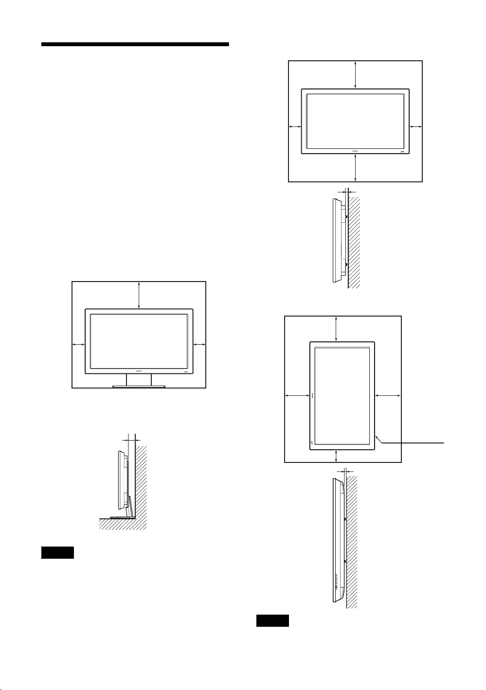
設置するときのご注意
周囲に充分なスペースをとる
・ 内部の温度上昇を防ぐため、密閉状態にならないよ
うにディスプレイの周囲に少なくとも下図に示す距
離をあけて、通風を確保してください。
・ 周囲の温度は 0℃〜 35℃の範囲でご使用ください。
・ スタンドを使用するときは、必ず専用ディスプレイ
スタンド SU-50FW(別売)をご使用ください。
・ ブラケットやネジ、ボルトなどの設置機材について
特定の製品を指定することはできません。実際の設
置は、お買い上げ店またはソニーのサービス窓口に
ご依頼ください。設置についてはソニーのサービス
窓口にご相談ください。
・ 通電中は高温になる部分があり、やけどの原因とな
ります。通電中やスタンバイにした直後は、本機の
上面、後面には手を触れないでください。
ディスプレイスタンドを使用する場合
前面
20
10
10
水平方向で使用する場合
前面
25
10 10
25
側面
垂直方向で使用する場合
前面
20
5
単位:cm
側面
ご注意
スタンド(別売)を取り付けたままの状態で、運搬や
設置を行うときは、3 人以上で作業してください。
JP
10
10
単位:cm
設置の際
5
単位:cm
25
は、必ず1
POWER
(パワー)
スイッチを
右下にして
ください。
25
10
側面
ご注意
本機を垂直方向で使用するときは、スピーカー SSSP50FW(別売)は使用できません。
Page 11

各部の名称と働き
前面パネル
JP
1 INPUT
INPUT または OPTION 端子に接続した機器か
らの入力信号を選びます。
の順に入力信号を切り換えます。
OPTION スロットに映像系のオプションアダプ
ターがないときは、スキップします。
2 MENU(23 ページ)
34f/F(音量調節 / カーソル移動)ボタン
スピーカーから出る音量を調節するときに使用
します。また、メニューを表示しているときは、
カーソル(黄色)の移動や数値などの設定をす
るときに使用します。
5 ENTER
メニューで、設定した内容を確定するときに使
用します。
6 1
本機の電源を入 / 切(スタンバイ)します。
ご注意
パネル保護のため、電源の入 / 切(スタンバイ)
に時間がかかります。再度、電源を入れる場合
は約 8 秒待ってから行ってください。
7 リモコンセンサー
8 POWER/STANDBY(電源 / スタンバイ)イ
ンジケーター
・ 本機の電源を入れると緑色に点灯します。
・ 本機がスタンバイ状態のとき、赤色に点灯し
ます。また PC 入力のとき、パワーセービン
グ状態になると、インジケーターがオレンジ
色に点灯します。
POWER/STANDBY インジケーターが点滅し
たときは、41 ページをご覧ください。
ご注意
「マルチディスプレイ設定」の「LED」が「切」
で、「ポジション設定」が右下以外の場合は、
ディスプレイの電源が入っていてもインジケー
ターは緑点灯しません(無信号時 / 未対応信号
時を除く)。
11
JP
Page 12

サイドパネル
OPTION1 スロット
(VIDEO/COM)
端子 説明
1REMOTE
(10BASE-T/100BASE-TX)
2AUDIOOUTL/R
(ピンジャック)
本機を 10BASE-T/100BASE-TX の LAN ケーブルでネットワークと接続
します。PC からネットワーク経由でディスプレイのコントロールおよ
び各種設定ができます。
・ 安全のために、周辺機器を接続する際は、過大電圧を持つ可能性があ
・ 本端子を使用する際は、「ネットワークポート」の「本体」を選択し
AUDIO 端子に入力した音声信号の、画面に表示されている信号の音声
を出力します。2画面(P&P、PinP)のときは、アクティブ * 画面の音
声信号を出力します。
「音質モード」の設定は反映されません。
OPTION2 スロット
(VIDEO)
ご注意
るコネクターをこの端子に接続しないでください。
接続については本書の指示に従ってください。
てください(34 ページ)。
ご注意
12
JP
Page 13

端子 説明
3HD15IN
(D-sub15 ピン)
4DVIIN
(DVI-D24 ピン)
5MONITORCONTROL
ADAPTOR(モニターコントロー
ルアダプター)
(BKM-FW21 プリインストール)
6OPTION1 スロット
(VIDEO/COM ポート)
7VIDEOINPUTADAPTOR
(ビデオ入力アダプター)
(BKM-FW10 プリインストール)
8OPTION2 スロット
(VIDEOポート)
音声が出力され、入力の切り換えが可能な状態
*
RGB/COMPONENT:映像機器や PC のアナログ RGB 信号出力端子、ま
たはコンポーネント信号出力端子と接続します。46 ページをご覧くださ
い。
AUDIO:音声信号を入力します。映像機器や PC の音声出力端子と接続
します。
ご注意
コンポーネント信号を入力する際は 13、14 ピンに同期信号を入力しな
いでください。画像が正しく表示されない場合があります。
DVI:映像機器などのデジタル RGB 信号出力端子と接続します。HDCP
のコンテンツ保護に対応しています。
AUDIO:音声信号を入力します。映像機器などの音声出力端子と接続し
ます。
CONTROLSIN/OUT(ミニジャック):ディスプレイを含む他機器の
CONTROLS 端子に接続すると、1 台のリモコンで複数の機器を操作で
きます。本機の CONTROLSOUT 端子とほかの機器の CONTROLSIN
端子、本機の CONTROLSIN 端子とほかの機器の CONTROLSOUT 端
子を接続します。
REMOTE(D-sub9 ピン):RS-232C プロトコルを使って本機を遠隔操作
するときに使います。詳しくはお買い上げ店またはソニーのサービス窓
口にご相談ください。
ご注意
・ このアダプターは OPTION2スロットでは動作いたしません。
・ REMOTE 端子は 1 の REMOTE 端子 (LAN) と併用することはでき
・ REMOTE 端子を使用する際は、「ネットワークポート」の「Option1」
映像信号および通信機能に対応したスロットです。オプションアダプ
ター(BKM-FWシリーズなど)を装着すると、入力信号端子を拡張し
たり、ネットワーク経由でディスプレイ制御を行うことが可能となりま
す。
SVIDEOIN(ミニ DIN4 ピン):映像機器の S ビデオ信号出力端子と接
続します。
SVIDEOOUT(ミニ DIN4 ピン):映像機器の Sビデオ信号入力端子と
接続します。SVIDEOIN の映像を出力します。
VIDEOIN(BNC 型):映像機器のビデオ信号出力端子と接続します。
VIDEOOUT(BNC 型):映像機器のビデオ信号入力端子と接続します。
VIDEOIN の映像を出力します。
AUDIOINL/R(ピンジャック):映像機器の音声出力端子と接続しま
す。
映像信号に対応したスロットです。このスロットには、ビデオ信号入出
力系のオプションアダプターを装着することができます。通信機能のあ
るオプションアダプターは、6 の OPTION1 スロットに取り付けてくだ
さい。
JP
ません。
を選択してください(34 ページ)。
13
JP
Page 14

オプションアダプター
サイドパネル 6、8 の端子部はスロットイン方
式になっていて、以下のオプションアダプター
(別売)に付け換えることができます。
各アダプターの取り付けかたについては、お買
い上げ店またはソニーのサービス窓口にご相談
ください。
その他、機能拡張用オプションアダプター
BKM-FW シリーズについては、それぞれの取
扱説明書をご覧ください。
ビデオ入力アダプター BKM-FW10
OPTION2 スロット 8 にプリインストールさ
れているアダプターと同じものです。13 ページ
をご覧ください。
コンポーネント /RGB 入力アダプター
BKM-FW11
1 Y/G,PB/CB/B,PR/CR/R映像入力端子
(BNC 型):映像機器や PC のコンポーネン
ト信号出力端子またはアナログ RGB 信号出
力端子と接続します。
2 HD,VD同期信号入力端子(BNC 型):PC
の同期信号出力端子と接続します。
ご注意
コンポーネント信号を入力する際は HD,VD に同期信
号を入力しないでください。画像が正しく表示されな
い場合があります。
3 AUDIO(音声入力)端子(ステレオミニ
ジャック):音声信号を入力します。映像機
器や PC の音声出力端子と接続します。
RGB/ コンポーネントアクティブス
ルーアダプターBKM-FW12
1 RGB/COMPONENTIN(RGB/ コンポー
ネント信号入力)端子(D-sub15 ピン):
映像機器や PC のアナログ RGB 信号出力端子
またはコンポーネント信号出力端子と接続し
ます。コンポーネント信号をこの端子へ入力
する場合には、46 ページのピン配列を参考に
してください。
ご注意
コンポーネント信号を入力する際は 13、14 ピンに同
期信号を入力しないでください。画像が正しく表示さ
れない場合があります。
2 RGB/COMPONENTOUT(RGB/ コンポー
ネント信号出力)端子(D-sub15 ピン):
映像機器や PCのアナログ RGB信号入力端
子またはコンポーネント信号入力端子と接
続します。上記 1 の端子から入力された映
像を出力します。
3 AUDIOIN(音声入力)端子(ステレオミ
ニジャック):
音声信号を入力します。映像機器や PC の音
声出力端子と接続します。
ご注意
本機がスタンバイ状態のときや AC 電源が接続されて
いないときは、RGB/COMPONENTOUT 端子からは
出力されません。
モニターコントロールアダプター
BKM-FW21
OPTION1スロット 6 にプリインストールさ
れているアダプターと同じものです。13 ページ
をご覧ください。
ストリーミングレシーバーアダプター
BKM-FW50
詳しくは BKM-FW50 の取扱説明書をご覧くだ
さい。
14
JP
Page 15
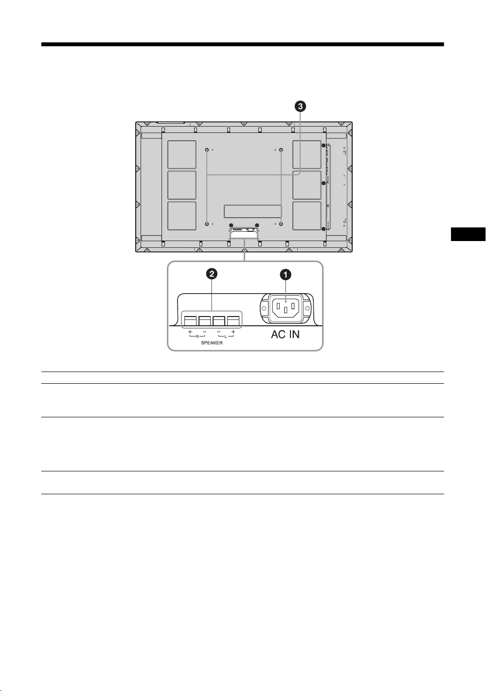
後面パネル
JP
各部 説明
1ACIN(電源入力)ソ
ケット
2SPEAKER(スピー
カー)端子
3スタンド取り付け用
フック
付属の電源コードをこのソケットとコンセントに接続します。電源コードを接
続すると、POWER/STANDBY インジケーターが赤色に点灯し、本機はスタン
バイ状態になります。21 ページをご覧ください。
スピーカー SS-SP50FW(別売)をこの端子に接続すると、画面に表示されてい
る信号の音声を出力し、より臨場感あふれる映像をお楽しみいただけます。ス
ピーカーの接続について詳しくは、スピーカーに付属の取扱説明書をご覧の上、
正しく接続してください。
また、スピーカーコードのまとめ方は、22 ページをご覧ください。
ディスプレイスタンドSU-50FW(別売)を取り付けるときに使用します。
15
JP
Page 16

リモコン
ボタンの機能
1 POWER(電源)ON スイッチ
押すと電源が入ります。
2 DVIボタン
DVIIN 端子に接続した機器からの入力信号を選びます。
3 HDMI ボタン
本機では使用しません。
4 SVIDEOボタン
SVIDEOIN 端子に接続した映像機器からの入力信号を選び
ます。
5 VIDEOボタン
VIDEOIN 端子に接続した映像機器からの入力信号を選びま
す。
6 PICTURE ボタン
「画質モード」を切り換えます。ボタンを押すごとに、「ダイ
ナミック」、「スタンダード」、「カスタム」、「カンファレン
ス」の順に切り換わります。
7 F/f/G/g/ ボタン
F/f/G/g
たり、数値などを設定します。 ボタンを押すと、選んだ
メニューや設定した内容を確定します。
「2 画面」モードでは、
り換えることができます。
8 ボタン
画面のアスペクト比を変更します。18 ページをご覧くださ
い。
9 MENU ボタン
画面にメニューを出すときに使用します。もう一度押すとメ
ニューが消えます。23 ページをご覧ください。
ボタンでメニューのカーソル(黄色)を移動させ
G/gボタンでアクティブな画面を切
ご注意
・ 数字ボタンの「5」および ボタンには、凸部(突起)が付いています。操作の目印としてお使いください。
・ 付属の単 3 形乾電池 2 本を、リモコンの電池挿入部内部の図を確認しながら、3 極と # 極を正しく入れてくだ
さい。
押してスライドさせて開け
,
JP
16
Page 17

0 IDMODE(ON/0-9/SET/C/OFF)ボタン
複数のディスプレイを使用しているとき、「インデックス番
号」を指定して、特定のディスプレイのみを操作することが
できます。
・ ON ボタン:「インデックス番号」を画面上に表示します。
・ 0-9 ボタン:操作したいディスプレイの「インデックス番
号」を入力します。
・ SET ボタン:入力した「インデックス番号」を設定しま
す。
・ C ボタン:入力した「インデックス番号」をクリアしま
す。
・ OFF ボタン:通常の画面に戻ります。
20 ページをご覧ください。
qa +/–ボタン
画像のコントラストを調整します。
qs +/–ボタン
音量を調整します。
qd ボタン
音を消します。もう一度押すと、音が出ます。
qf ボタン
「2 画面」モードを切り換えます。ボタンを押すごとに、
「P&P」、「PinP」、1画面の順に切り換わります。19 ページを
ご覧ください。
qg DISPLAY ボタン
現在選択されている入力、入力されている信号の種類および
「アスペクト」設定を画面に表示します。もう一度押すと表
示は消えます。表示された状態でしばらくたつと自動的に表
示は消えます。
qh OPTION1/OPTION2 ボタン
オプションアダプターを装着した際、そこに接続した機器か
らの入力信号を選びます。OPTION1 端子からの信号入力を
選ぶには OPTION1 ボタンを押し、OPTION2 端子からの信
号入力を選ぶには OPTION2 ボタンを押します。
装着したオプションアダプターに入力が複数ある場合は、ボ
タンを押すたびに入力が切り換わります。
qj HD15 ボタン
HD15IN 端子に接続した機器からの入力信号を選びます。メ
ニューの設定により RGB 信号かコンポーネント信号の自動
選択またはマニュアル選択ができます。
qk STANDBY ボタン
押すとスタンバイ状態になります。
JP
17
JP
Page 18

リモコンの特別ボタン
ワイド切換を使う
画面のアスペクト比を変更することができます。
ちょっと一言
「画面」メニューからも「アスペクト」を設定するこ
とができます。30、31 ページをご覧ください。
ビデオ、DVD などの映像機器からの入力の場
合(PC 入力以外)
4:3 の映像ソース
16:9 の映像ソース
m
ワイドズーム
4:3
フル
ワイド
ズーム
4:3
フル
ズーム
ズーム
m
PC 入力の場合
以下のイラストは解像度 800 × 600 の入力を
行った場合です。
リアル
フル 1
フル 2
18
JP
Page 19

2 画面設定を使う
PC とビデオなど、ふたつの異なる信号の映像を、並べて表示します。またアクティブ
な画面の入れ換えや、画面の大きさのバランスも自由に変えられます。
また「画面」メニューからも「2画面設定」を設定することができます。
28 ページをご覧ください。
アクティブな画面を示すカーソル
P&P の場合
AとBの横幅は同
じになります。
高さは各画像のアス
ペクト比によって決
まります。
A と B の横幅は同じにな
ります。
高さは各画像のアスペク
ト比によって決まります。
PinP の場合
Gボタンを押す
A の横幅は B の横幅
より大きくなりま
す。
A のアスペクト比が
4:3 なら、A の高さ
はパネルのサイズと
等しくなります。
g
ボタンを押す
右側の B がアクティ
ブな画像となりま
す。
g
ボタンを押す
主画面 (A) の中に副
画面 (B) が表示され
ます。
G
/gボタンを押す
副画面 (B) がアク
ティブな画像となり
ます。
gボタンを押す
B の横幅は A の横幅より大
きくなります。
B のアスペクト比が 4:3
なら、B の高さはパネルの
サイズと等しくなります。
f
ボタンを押す
右側の B がアクティブな画
像のまま、小さくなりま
す。
副画面 (B) の画面が大き
くなります。
f
ボタンを押す
副画面 (B) の画面が小さく
なります。
JP
ボタンを押す
副画面 (B) の位置が
移動します。
F
ボタンを押す
ちょっと一言
・ アクティブな画面を示すカーソルは、5秒たつと表示が消えます。
・ 画面の大きさは 7 段階で変えられます。(P&P の場合)
19
JP
Page 20

IDMODE ボタンを使う
複数のディスプレイを使用しているとき、「イ
ンデックス番号」を指定して、特定のディスプ
レイのみを操作することができます。
1 ON ボタンを押す。
「インデックス番号」が、画面左下のメ
ニューに黒い文字で表示されます(「イン
デックス番号」は、1 から 255 の範囲で、あ
らかじめ各ディスプレイに設定されていま
す)。
インデックス番号
4 設定変更などの操作が終了したら、OFF
ボタンを押す。
ディスプレイは通常の画面に戻ります。
インデックス番号を訂正するには
C ボタンを押して、現在入力されている「イン
デックス番号」を消去します。手順 2 に戻り、
新しい「インデックス番号」を入力します。
117
2 リモコンの 0 から 9 のボタンで、操作した
いディスプレイの「インデックス番号」
を入力する。
すべてのディスプレイの「インデックス番
号」の右に、入力した数字が表示されます。
入力された番号
3 SET ボタンを押す。
選択したディスプレイの文字が緑色に変わ
り、その他のディスプレイの文字は赤色に
変わります。
ちょっと一言
ディスプレイの「インデックス番号」を変更するに
は、32 ページの「コントロール設定」の「インデッ
クス番号」をご覧ください。
これで特定のディスプレイ(文字が緑色に
変わったディスプレイ)のみを操作できま
す(POWER(電源)ON スイッチ、
STANDBY ボタン、および IDMODE-OFF
ボタンの操作だけは、ほかのディスプレイ
にも有効です)。
JP
20
Page 21

接続
接続上のご注意
・ 各機器の電源を切ってから接続を行ってください。
・ 接続ケーブルはそれぞれの端子の形状に合った正し
いものをお選びください。
・ 接続ケーブルは端子にしっかり差し込んでくださ
い。接続が悪いとノイズの原因となります。
・ ケーブルを抜くときは必ずプラグを持って抜いてく
ださい。決してケーブルそのものを引っ張らないで
ください。
・ 接続の詳細については、各機器の取扱説明書をご覧
ください。
・ 電源コードのプラグは、ACIN ソケットに、まっ
すぐ突き当たるまで差し込んでください。
・ 付属の AC プラグホルダーは、使用する電源コード
のプラグが確実に固定できる方を選んでお使いくだ
さい。
スピーカーの接続
スピーカー SS-SP50FW(別売)を接続して、
臨場感あふれる音声をお楽しみいただけます。
スピーカーの接続について詳しくは、スピー
カーに付属の取扱説明書をご覧の上、正しく接
続してください。また、スピーカーコードのま
とめ方は、22 ページをご覧ください。
電源コードの接続
1 電源コードを底部の ACIN ソケットに差
し込み、AC プラグホルダー(付属)を電
源コードに取り付ける。
ACIN
ソケット
電源
コード
AC プラグ
ホルダー
JP
2 AC プラグホルダーをスライドさせて、本
体側の ACIN ソケットカバーにはめ込
む。
ACIN ソケット
カバー
電源コードをはずすには
AC プラグホルダーのつめをはさみ、ロックを
解除してからプラグをつかみ、電源コードをは
ずしてください。
21
JP
Page 22

ケーブルを処理する
ケーブルホルダーを使う
付属のケーブルホルダー(× 6)を使って、ケーブル類をすっきりとまとめることができます。ケーブ
ルホルダーは、以下のように取り付けます。
本機後面
123
22
JP
Page 23

メニューの設定
メニュー一覧
1 MENU ボタンを押す。
2 F/fボタンで設定したいメニューのアイ
3 ボタンまたはg ボタンを押す。
2,3
メニュー表示の言語を変更する
メニュー表示とメッセージの言語を、
「English」、「Français」、「Deutsch」、「Español」、
1
メニュー画面から以下の項目を設定することができます。
メニュー画面 設定 / 変更できる項目
画質 / 音質
画質モード:(25、26 ページ)
画質モード調整(25、27 ページ)
音質モード:(26 ページ)
音質モード調整(26 ページ)
「Italiano」、「 」から選びます。
初期設定では「English」(英語)に設定されて
います。
32 ページをご覧ください。
コンを選ぶ。
メニューの操作を終了するには、MENU ボ
タンを押します。
JP
画面
2 画面設定(28 ページ)
マルチディスプレイ設定(29 ページ)
アスペクト:(30、31 ページ)
画面調整(30、31 ページ)
23
JP
Page 24
メニュー画面 設定 / 変更できる項目
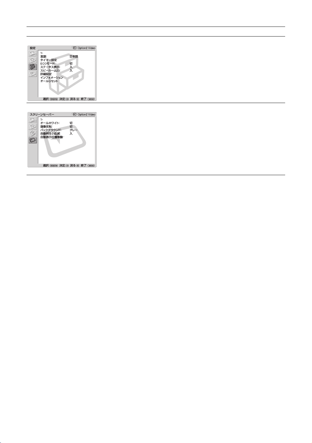
設定
言語:(32 ページ)
タイマー設定(32 ページ )
ECO モード:(32 ページ)
ステータス表示:(32 ページ)
スピーカー出力:(32 ページ)
詳細設定(32 ページ)
インフォメーション(34 ページ)
オールリセット(34 ページ)
スクリーンセーバー
オールホワイト:(35 ページ)
画像反転:(35 ページ)
バックグラウンド:(35 ページ)
自動明るさ低減:(35 ページ)
自動表示位置移動(35 ページ)
* メニュー画面の下の行に表示されているアイコンは、設定項目によっては、働かないことがあります。
24
JP
Page 25

画質 / 音質メニュー
ビデオ入力の場合
項目を選んで設定を変えるには、F/f/G/g ボ
タンを押します。
設定を確定するには ボタンを押します。
「画質 / 音質」メニューには、以下の項目が含
まれます。
画質モード
画質モード調整
「ダイナミック」:映像の輪郭を強調しコントラストを最大限に上げます。
「スタンダード」:標準的な設定です。
「カスタム」:お好みに合わせて細かく調整できます。
「カンファレンス」:蛍光灯下でのビデオ会議に適した画質になります。
ちょっと一言
・ リモコンの PICTURE ボタンでも「画質モード」の設定を切り換えることができま
す。
・ 各入力ごとに「画質モード」を設定することができます。
ご注意
「カンファレンス」は、ご使用の環境やビデオ会議システムによっては効果が少ない
場合があります。その場合は画質調整をしたり、他の「画質モード」の設定に切り
換えるなどしてください。
それぞれの「画質モード」で設定や調整を行うことができます。
「コントラスト」:コントラストの強弱を調整します。
「明るさ」:映像の明るさを調整します。
「色の濃さ」:色の濃淡を調整します。
「色あい」:映像の色調を調整します。
「シャープネス」:映像の輪郭の強弱を調整します。
「NR」:接続した機器からのノイズを軽減します。「切」、「低」、「中」、
「高」から強弱を設定することができます。
「シネモーション」:「自動」を選ぶと、映画の映像素材を検知し、リバー
ス 3-2プルダウンまたはリバース 2-2プルダウン処理によって画面表示を
自動的に最適化します。
動画がより鮮明かつ自然に見えます。「切」を選ぶと、この検知を行いま
せん。
「ダイナミックピクチャー」:「入」を選ぶと白をより白く、黒をより黒く
してコントラストを強めます。
「ガンマ補正」:映像の明暗部分のバランスを自動的に調整することができ
ます。「高」、「中」、「低」から強弱を設定することができます。
「色温度」
「高」:青みがかった白色になります。
「中」:中間の白色になります。
「低」:赤みがかった白色になります。
「カスタム」:お好みに合わせて、白色の色調を調整し設定することが
できます。
「標準」:「画質モード調整」のすべての設定項目を初期設定に戻します。
ご注意
入力信号がビデオまたは S ビデオで、映像信号のカラー方式が NTSC でない場合、
「色あい」は調整できません。
JP
25
JP
Page 26

音質モード
各種「音質モード」によって、スピーカー SS-SP50FW(別売)から出力
される音声を調整できます。
「ダイナミック」:高音と低音を強調します。
「スタンダード」:標準的な設定です。
「カスタム」:お好みに合わせて細かく調整できます。
音質モード調整
「高音」:高音の強弱を調整します。
「低音」:低音の強弱を調整します。
「バランス」:スピーカーの左右出力バランスを調整します。
「サラウンド」:映像の種類に合わせて、サラウンドモードを選ぶことがで
きます。
「切」:サラウンド出力をしません。
「ホール」:映画や音楽などのステレオ音声をより臨場感のある音にし
ます。
「シミュレート」:通常の放送やニュース番組のモノラル音声を擬似的
にステレオ音声にして臨場感を高めます。
「標準」:「音質モード調整」のすべての設定項目を初期設定に戻します。
ちょっと一言
・ それぞれの「画質モード」ごとに、「画質モード調整」(「コントラスト」、「明るさ」、「色の濃さ」など)を設定する
ことができます。
・「音質モード」で「カスタム」を選択しているときは、「音質モード調整」(「高音」、「低音」)を設定することがで
きます。
ご注意
・「2 画面」モード時、「画質 / 音質」メニューの項目はすべて選択不可能となります。
・ 現在の入力が無信号の場合、「画質 / 音質」メニューの項目はすべて選択不可能となります。
PC 入力の場合
入力を PC 入力に切り換えた場合、PC 用の「画
質 / 音質」メニューとなります。
PC 用の「画質 / 音質」メニューには、以下の
項目が含まれます。
画質モード
JP
26
「ダイナミック」:映像の輪郭を強調しコントラストを最大限に上げます。
「スタンダード」:標準的な設定です。
「カスタム」:お好みに合わせて細かく調整できます。
「カンファレンス」:蛍光灯下でのビデオ会議に適した画質になります。
ちょっと一言
・ リモコンの PICTURE ボタンでも「画質モード」の設定を切り換えることができま
す。
・ 各入力ごとに「画質モード」を設定することができます。
ご注意
「カンファレンス」は、ご使用の環境やビデオ会議システムによっては効果が少ない
場合があります。その場合は画質調整をしたり、他の「画質モード」の設定に切り
換えるなどしてください。
Page 27

画質モード調整
それぞれの「画質モード」で設定や調整を行うことができます。
「コントラスト」:コントラストの強弱を調整します。
「明るさ」:映像の明るさを調整します。
「ガンマ補正」:映像の明暗部分のバランスを自動的に調整することができ
ます。「高」、「中」、「低」から強弱を設定することができます。
「色温度」
「高」:青みがかった白色になります。
「中」:中間の白色になります。
「低」:赤みがかった白色になります。
「カスタム」:お好みに合わせて、白色の色調を調整し設定することが
できます。
「標準」:「画質モード調整」のすべての設定項目を初期設定に戻します。
音質モード
音質モード調整
ちょっと一言
・ それぞれの「画質モード」ごとに、「画質モード調整」(「コントラスト」、「明るさ」、「色の濃さ」など)を設定する
ことができます。
・「音質モード」で「カスタム」を選択しているときは、「音質モード調整」(「高音」、「低音」)を設定することがで
きます。
ご注意
・「色の濃さ」
時は調整できません。
・「2 画面」モード時、「画質 / 音質」メニューの項目はすべて選択不可能となります。
・ 現在の入力が無信号の場合、「画質 / 音質」メニューの項目はすべて選択不可能となります。
、「色あい」、「シャープネス」、「NR」、「シネモーション」、「ダイナミックピクチャー」は、PC 入力
各種「音質モード」によって、スピーカー SS-SP50FW(別売)から出力
される音声を調整できます。
「ダイナミック」:高音と低音を強調します。
「スタンダード」:標準的な設定です。
「カスタム」:お好みに合わせて細かく調整できます。
「高音」:高音の強弱を調整します。
「低音」:低音の強弱を調整します。
「バランス」:スピーカーの左右出力バランスを調整します。
「サラウンド」:映像の種類に合わせて、サラウンドモードを選ぶことがで
きます。
「切」:サラウンド出力をしません。
「ホール」:映画や音楽などのステレオ音声をより臨場感のある音にし
ます。
「シミュレート」:通常の放送やニュース番組のモノラル音声を擬似的
にステレオ音声にして臨場感を高めます。
「標準」:「音質モード調整」のすべての設定項目を初期設定に戻します。
JP
27
JP
Page 28

画面メニュー
ビデオ入力の場合
項目を選んで設定を変えるには、F/f/G/g ボ
タンを押します。
設定を確定するには ボタンを押します。
「画面」メニューには、以下の項目が含まれま
す。
2 画面設定
利用可能な 2 画面の組み合わせ
DVI
HD15
* 「OPTION1+OPTION2」は未対応です。
1)
「HD15 信号」の「本体」が「YUV」、「Option1」もしくは「Option2」が「RGB」に設定されている場合に対応
します。
2)
「HD15 信号」の「本体」が「RGB」、「Option1」もしくは「Option2」が「YUV」に設定されている場合に対応
します。
RGB
コンポーネント
PCとビデオなど、ふたつの異なる信号の映像を、並べて表示します。
「2 画面」
「切」:「2 画面」機能を解除します。
「P&P」:ふたつの映像を同時に並べて表示します。
「PinP」:ふたつの映像を主画面の中に副画面として表示します。
P&P の場合
「操作画面」:操作する画面を選びます。
「左操作」:左の画面がアクティブとなり、操作可能になります。
「右操作」:右の画面がアクティブとなり、操作可能になります。
「画面入替」:左右の画面を入れ換えます。
「画サイズ」:左右の画面の大きさのバランスを調整します。G/gボタンを
押しながら調整し、 ボタンを押して決定します。(19 ページ)
PinP の場合
「操作画面」:操作する画面を選びます。
「主操作」:主画面がアクティブとなり、操作可能になります。
「副操作」:副画面がアクティブとなり、操作可能になります。
「画面入替」:主画面と副画面を入れ替えます。
「副画面サイズ」:副画面の大きさを設定します。「大」、「小」のどちらか
を選びます。
「副画面位置」:副画面を表示させたい位置を設定します。
ンで選び、 ボタンで設定します。
DVI
HD15 OPTION1/2
RGB
コンポーネント
RGB
コンポーネント
1)
F/f/G/g ボタ
ビデオ
2)
Sビデオ
28
JP
Page 29

マルチディスプレ
イ設定
本機を複数台接続して、ビデオウォールを構成するための設定をします。
「マルチディスプレイ」
「切」:1 画面表示になります。
「2 × 2」/「3 × 3」/「4 × 4」:本機を縦横それぞれに2、3、4台と
複数台接続する場合に設定します。
「1 × 2」/「1 × 3」/「1 × 4」:本機を横に2、3、4台と複数台接続
する場合に設定します。
「2 × 1」/「3 × 1」/「4 × 1」:本機を縦に2、3、4台と複数台接続
する場合に設定します。
「ポジション設定」:個々のディスプレイの画面位置を、
F/f/G/g ボタン
で選びます。 ボタンで位置を確定します。
「出画形式」:図にある 2種類の映像出力形式から選びます。いずれかの形
式を選択することにより、水平・垂直位置を手動で調整しなくても、最適
な映像出力が得られます。「タイル」または「ウィンドウ」を選んでくだ
さい。
「タイル」
ジャストスキャン
「ウィンドウ」
オーバースキャン
JP
それぞれの画面に、映像信号を
完全に表示します。
ひとつの大きな映像を、複数の画面
で自然に表示します。
映像信号の一部は、ベゼルの後ろに
隠れます。
「LED」:「入」を選ぶと、本機前面の POWER/STANDBYインジケーター
(11 ページ)が点灯しつづけます。「切」を選ぶと、消灯します。
ご注意
・「マルチディスプレイ」は、ビデオ入力の場合は現在の「アスペクト」を極力維
持した映像を、PC入力の場合は「アスペクト」の「フル 2」の映像を表示するこ
とができます。
・「2 画面」機能を使用していないときにのみ、「マルチディスプレイ設定」を設定
することができます。
・「ポジション設定」を右下に設定すると、「LED」を「切」にしても、POWER/
STANDBYインジケーターが緑色に点灯します。インジケーターは、無信号時 /
未対応信号時も含め、ディスプレイがオフ(スタンバイ)時、異常検出時、ス
リープ状態時にも点灯します。
29
JP
Page 30

アスペクト
「ワイドズーム」:ゆがみを最低限に抑えて映像を拡大し、画面いっぱいに
表示します。
「ズーム」:アスペクト比を保ったまま、映像を拡大します。18 ページをご
覧ください。
「フル」:4:3の映像ソース(標準画質)を水平方向に拡大し、画面いっぱ
いに表示します。16:9の映像ソース(高画質)の場合は、そのままのアス
ペクト比で表示します。
「4:3」:4:3の映像ソース(標準画質)を、そのままのアスペクト比で表示
します。
ちょっと一言
・ リモコンの ボタンでも「アスペクト」の設定を切り換えることができます。
・ 映画などの DVD映像で、黒帯のある映像を画面いっぱいに映して楽しみたいと
きは、「ズーム」を選んでください。
・「ワイドズーム」または「ズーム」が選ばれているときは、映像の「水平位置」、
「垂直位置」、「垂直サイズ」を調整することができます。30 ページをご覧くださ
い。
ご注意
「2 画面」機能または「マルチディスプレイ」使用時は、「アスペクト」はできませ
ん。
画面調整
ご注意
・「画面調整」は、「2 画面」機能や「マルチディスプレイ設定」の使用中は設定できません。
・ 現在の入力が無信号の場合、「画面」メニューの項目は「2 画面設定」と「マルチディスプレイ設定」を除いて、
すべて選択不可能となります。
「水平サイズ」:映像の左右の大きさを調整します。G/g ボタンと ボタ
ンで調整結果を確定します。
「水平位置」:映像の左右の位置を調整します。
調整結果を確定します。
「垂直サイズ」:映像の上下の大きさを調整します。
ンで調整結果を確定します。
「垂直位置」:映像の上下の位置を調整します。
調整結果を確定します。
「標準」:「画面調整」のすべての設定項目を初期設定に戻します。
G/g ボタンと ボタンで
F/fボタンと ボタ
F/f ボタンと ボタンで
30
JP
Page 31

PC 入力の場合
入力を PC 入力に切り換えた場合、PC 用の「画
面」メニューとなります。
PC 用の「画面」メニューには、以下の項目が
含まれます。
2 画面設定
マルチディスプレ
イ設定
アスペクト
画面調整
ビデオ入力時の「2画面設定」(28 ページ)をご覧ください。
ビデオ入力時の「マルチディスプレイ設定」(29 ページ)をご覧ください。
「フル 1」:アスペクト比を保ったまま、映像を画面垂直方向いっぱいに拡
大します。映像の周囲に黒い帯が出ることがあります。
「フル 2」:映像を画面いっぱいに拡大します。
「リアル」:映像を元のままのドット数で表示します。
ご注意
「2 画面」機能または「マルチディスプレイ設定」使用時は、「アスペクト」は設定
できません。
「自動調整」:「実行」を選ぶと接続した PCからの入力信号を受けたとき、
自動的に映像の位置や位相を調整します。入力信号の種類によっては、
「自動調整」がうまく働かないことがあります。その場合は、下記の項目を
手動で調整してください。
「画位相」:画面がちらちらしているとき、位相を調整します。
「ドットピッチ」:映像におかしな縞模様が出るとき、ピッチを調整しま
す。
「水平サイズ」:映像の左右の大きさを調整します。
ンで調整結果を確定します。
「水平位置」:映像の左右の位置を調整します。
調整結果を確定します。
「垂直サイズ」:映像の上下の大きさを調整します。
ンで調整結果を確定します。
「垂直位置」:映像の上下の位置を調整します。
調整結果を確定します。
「標準」:「画面調整」のすべての設定項目を初期設定に戻します。
G/g ボタンと ボタ
G/g ボタンと ボタンで
F/fボタンと ボタ
F/f ボタンと ボタンで
JP
ご注意
現在の入力が無信号の場合、「画面」メニューの項目は「2 画面設定」と「マルチディスプレイ設定」を除いて、す
べて選択不可能となります。
31
JP
Page 32

設定メニュー
項目を選んで設定を変えるには、F/f/G/g ボ
タンを押します。
設定を確定するには ボタンを押します。
「設定」メニューには、以下の項目が含まれま
す。
言語
タイマー設定
ECO モード
ステータス表示
スピーカー出力
メニュー表示の言語を、「English」、「Français」、「Deutsch」、「Español」、
「Italiano」、「 」の中から選びます。
時刻合わせ、内蔵時計の表示、およびあらかじめ決めた時間に自動で電源
を入 / 切するタイマー機能の設定をすることができます。
「時刻設定」:曜日と時刻を設定します。
「時計表示」:「入」を選ぶと、設定された現在時刻を表示します。
「電源タイマー」:自動的に電源を入 / 切する時間を設定します。
ご注意
時刻が大幅にずれたりするときは、内蔵電池の消耗が考えられます。お買い上げ店
またはソニーのサービス窓口に電池の交換をご依頼ください(有料)。
「切」:省電力機能を使用しません。
「低」/「高」:明るさを変化させて、消費電力を減らします。
「入」を選ぶと、電源を入れたときに入力信号と「アスペクト」の情報が、
画面に約 20秒間表示されます。また、入力信号を切り換えると、入力信
号の情報が約 5秒間表示されます。「切」を選ぶと、情報は表示されませ
ん。
ちょっと一言
リモコンの DISPLAY ボタンで、「ステータス表示」の設定にかかわらず入力信号と
「アスペクト」の情報を表示させることができます。
「入」:スピーカーから音声を出力します。
「切」:スピーカーから音声を出力しません。
ご注意
「スピーカー出力」が「切」のときは、「音質モード」、「音質モード調整」は選択で
きません。
詳細設定
JP
32
「コントロール設定」:本機およびリモコンの操作に関する設定を行いま
す。
「インデックス番号」:必要に応じて、本機のインデックス番号を変更
します。
決定します。
ご注意
「インデックス番号」を設定するときは、本機のボタンをご使用ください。リモコン
では設定できません。
F/f ボタンでインデックス番号を設定し、ENTER ボタンで
Page 33

「コントロールモード」
「本体+リモコン」:本機のボタンおよびリモコンで、本機を操作で
きます。
「本体のみ」:リモコンでの操作を無効にします。本機のボタンでの
み、本機の設定をすることができます。
「リモコンのみ」:リモコンだけで操作したいときに、本機の操作を
無効にします。リモコンでのみ、本機の設定をすることができま
す。
ご注意
この項目を設定するとき、リモコンからか本体からかによって選べるモードが
異なります。リモコンの
「リモコンのみ」を選べます。本機の ENTER ボタンで設定するときは、「本体
+リモコン」か「本体のみ」を選べます。
ボタンで設定するときは、「本体+リモコン」か
「自動画面調整」
「入」:各入力信号ごとに調整値(サイズ、位置など)を保存でき、最
後の調整値が自動的に適用されます。
「切」:入力信号を切り換えても自動調整されず、初期設定が適用され
ます。
「オートシャットオフ」
「入」:ビデオ入力、Sビデオ入力に無信号の状態が約5分続くと、本機
は自動的にスタンバイ状態になります。また DVI 入力、本体 HD15 入
力(RGB/ コンポーネント)に無信号の状態が約 30秒続くと、自動的
にパワーセービング状態になります。
「切」:各入力に無信号の状態が続いても、本機の電源は切れません。
ちょっと一言
スタンバイ状態のときは 1POWER(パワー)スイッチまたはリモコンの
POWERONスイッチを押すと、電源が入ります。またパワーセービング状態の
ときは、信号が入力されると自動的に電源が入ります。
オプションアダプターの RGB/ コンポーネント入力が選択されているときは、
入力が無信号になってもパワーオンの状態が続きます。
「カラーマトリクス」:HD15IN(RGB/COMPONENT)端子に接続した映
像機器の映像が自然な色あいになるように設定できます。
「Y/CB/CR」:信号フォーマットが 480i(525i)または 480p(525p)の
場合
「Y/PB/PR」:信号フォーマットが 720p(750p)または 1080i(1125i)
の場合
ご注意
「カラーマトリクス」はコンポーネント入力時のみ、設定できます。
「オーバースキャン」:オーバースキャンとアンダースキャンのどちらで画
像を表示するかを設定します。
「入」:オーバースキャンして画像を表示します。
「切」:アンダースキャンして画像を表示します。
「同期モード」:HD15IN(RGB/COMPONENT)端子の 13 番ピンに入力
される信号によって、モードを設定します。設定できる信号は、575/50i、
480/60i のみです。
「同期信号」:水平信号またはコンポジット同期信号が入力される場合
に選択します。
「映像信号」:映像信号が入力される場合に選択します。
JP
33
JP
Page 34

ご注意
・「同期モード」は、PC 入力時は設定できません。
・ コンポジット同期の信号レベルによっては正しく画像が表示されない場合があり
ます。その際は、「同期モード」の設定を変更してください。
・「同期信号」しか選べない入力があります。この場合は水平・垂直同期信号を 13、
14 ピンに入力してください。
・ オプションボード入力では、「同期モード」の設定はできません。
・ 本機はコンポジットシンクおよび 576/60p の 3 値シンクには対応していません。
・「同期モード」で「映像信号」を選択した場合、2 画面への切り換えはできませ
ん。
「HD15 信号」
「本体」/「Option1」/「Option2」:本体およびオプションボードの
HD15IN(RGB/COMPONENT)端子に接続された映像機器や PC の
信号の種類を設定します。
「自動」:アナログ RGBまたはコンポーネント信号を自動的に選別
します。
「RGB」:アナログ RGB信号入力の場合に選択します。
「YUV」:コンポーネント信号入力の場合に選択します。
ちょっと一言
利用可能な 2 画面の組み合わせについては、28 ページをご覧ください。
「カラー方式」:「自動」、「NTSC」、「NTSC4.43」、「PAL」、「PAL-M」、
「PAL-N」、「PAL60」から映像信号のカラー方式を設定します。「自動」を
選ぶと、カラー方式が自動的に設定されます。
ご注意
「カラー方式」は、PC 入力時は設定できません。
「ネットワークポート」:本機を遠隔操作する場合のポートを設定します。
「切」:ネットワークポートを使用しない場合に設定します。スタンバ
イ時の消費電力を抑えることができます。
「本体」:本機の REMOTE(LAN)端子に接続した PC で、ディスプレ
イの各種設定を行います。(38 ページ )
「Option1」:OPTION1 スロットの REMOTE 端子や LAN 端子に接続し
た PC でディスプレイの各種設定を行います。(38 ページ )
「IPAddressSetup」:本機やオプションアダプターの REMOTE(LAN)端
子と、LAN ケーブルで接続された PC などの機器とが通信できるように
IP アドレスを設定します。
「SpeedSetup」:本機やオプションアダプターの REMOTE(LAN)端子
と、LAN ケーブルで接続された PC などの機器との間の通信速度を設定し
ます。
ちょっと一言
「IPAddressSetup」と「SpeedSetup」の詳しい設定方法はネットワーク機能を
使う準備をする(36 ページ)をご覧ください。
インフォメーショ
ン
オールリセット
JP
34
「機種名」、「シリアル番号」、「累積通電時間」、「ソフトウェアバージョ
ン」、および「IPAddress」を表示します。
すべての調整値、設定値を工場出荷時の状態に戻します。
ご注意
「インフォメーション」に含まれる内容と、「インデックス番号」はリセットされま
せん。
Page 35

スクリーンセーバーメニュー
PC の画像のように、輝度の変化しない画像や
静止画の映像を長時間表示すると、画面に焼き
つきや残像が生じることがあります。これを補
正したり、軽減させるため、本機にはスクリー
ンセーバー機能が搭載されています。「スク
リーンセーバー」メニューには以下の項目が含
まれます。
オールホワイト
画像反転
バックグラウンド
自動明るさ低減
全画面を白く表示して、すでに焼き付きが発生している部分との差を小さ
くします。
「入」:画面の焼き付きや残像を低減させるために、画面全体に白画面を約
30分間表示します。
「切」:白画面表示を途中でやめる場合に選択します。
「入」:画像の色あいを反転させます。
「自動」:1日 1 回、設定した時刻に画像の色あいを反転します。
「反転開始時間」と「反転終了時間」の時刻を
タンで確定します。
「切」:画像を反転しません。
ご注意
「反転開始時間」と「反転終了時間」に同じ時刻を設定すると、反転開始時間の設定
が優先され、反転終了時間になっても反転表示は終了しません。反転表示時は反転
の反転になり、通常表示になります。
アスペクト比 4:3 画面を映すときなど、映像の出ないバックグラウンドの
明るさを設定します。「グレー」、「ダークグレー」、「ブラック」から選択
することができます。
ご注意
背景と映像の色(明るさ)が近いほど、焼き付きや残像は軽減されます。
「入」を選ぶと静止画など画面の変化が少ない画像の表示が 5 分以上続い
た場合、徐々に明るさを落として焼き付きや残像を軽減します。動画など
画面に大きい変化がある画像が表示されると、自動的に元の明るさに戻り
ます。
F/fボタンで設定し ボ
JP
自動表示位置移動
「表示位置移動」:「入」を選ぶと画像の表示位置を一定の時間経過後に自
動的に移動させます。焼き付きや残像を軽減します。
「移動量」:画像を移動させる場合、移動する量を「小」、「中」、「大」から
選択することができます。
「移動周期」:画像を移動させる場合、移動する周期を「16 秒」、「32 秒」、
「64 秒」、「320 秒」から選択することができます。
ご注意
「画像反転」と「自動表示位置移動」のどちらも「入」に設定されていると、画像反
転中に一定時間がたつと、反転した画像が表示位置を変えて表示されます。
35
JP
Page 36

ネットワーク機能
ネットワーク機能を
使う準備をする
使用上のご注意
・ 本機のソフトウェアの仕様は、改良のため予
告なく変更することがありますが、ご了承く
ださい。
・ アプリケーションソフトウェアは、この取扱
説明書の画面と一部異なる場合があります。
・ 安全の為に該当ポートには過電圧が加わる恐
れのないネットワークに接続してください。
・ このマニュアルに記載されている操作方法
は、下記の環境下でのみ動作を保証していま
す。
オペレーティングシステム:
MicrosoftWindowsXP/WindowsVista
ブラウザー:
MicrosoftInternetExplorer6.0 以上
・ ネットワーク上の安全のために、ユーザー名
とパスワードを設定して使用することを推奨
します。設定方法について詳しくはSetup
画面(39 ページ)をご覧ください。
セキュリティーの設定については、ネット
ワーク管理者にお尋ねください。
IP アドレスを設定する
本機は、10BASE-T/100BASE-TX の LAN ケー
ブルでネットワークに接続することができま
す。
本機を LAN に接続して使用するときは、次の
どちらかの方法で本機の IP アドレスを設定し
ます。IP アドレスの割り当てについては、サー
バーの管理者にお問い合わせください。
・ 固定の IP アドレスを本機に設定する
通常はこの方法で使用することを推奨しま
す。工場出荷時には自動取得になっておりま
すのでご注意ください。
・ IP アドレスを自動取得する
本機を接続するネットワーク上に DHCP サー
バーがある場合に、本機の IP アドレスを
DHCP サーバーから自動的に取得して使用す
ることもできます。この場合、本機を取り付
けたディスプレイの電源を入れるたび IP ア
ドレスが変わる場合があるのでご注意くださ
い。
IP アドレスを設定する前に、本機に LAN ケー
ブルでネットワークに接続し、電源を入れて 30
秒ほど待ってから設定を開始してください。
・ Microsoft および Windows は、米国 MicrosoftCorporation の米国およびその他の国における登録商
標です。
・ その他記載された商品名、会社名などは、各社の商標または登録商標です。
JP
36
Page 37

固定の IP アドレスを本機に設定する
1 MENU ボタンを押してメインメニューを
表示させる。
2 「設定」をF/fボタンで選び、 ボタン
を押す。
3 「詳細設定」をF/fボタンで選び、 ボ
タンを押す。
4 「IPAddressSetup」をF/fボタンで
ボタンを押す。
選び、
5 「Manual」をF/fボタンで選び、 ボ
タンを押す。
6 「IPAddress」、「SubnetMask」、
「DefaultGateway」、「PrimaryDNS」、
「SecondaryDNS」の中から設定する項
F/fボタンで選び、 ボタンを押
目を
す。
7 本機のF/fボタンまたはリモコンの数
字ボタンで、最初の枠に 3 桁の値(0 〜
255)を入力し、
タンを押す。
ボタンまたは g ボ
8 4 つの枠にそれぞれ 3 桁の値(0 〜 255)
を入力し、
F/fボタンで次に設定したい項目を
り
選び、
ボタンを押す。手順 6 に戻
ボタンを押す。
9 設定したいすべての項目に値を入力した
F/fボタンで「Execute」を選び、
ら、
ボタンを押す。
「実行」を選んで、 ボタンを押すと、IPアド
レスが手動で設定されます。
「取消」を選ぶと、変更前の設定に戻ります。
IP アドレスを自動取得する
1 MENU ボタンを押してメインメニューを
表示させる。
2 「設定」をF/fボタンで選び、 ボタン
を押す。
3 「詳細設定」をF/fボタンで選び、 ボ
タンを押す。
4 「IPAddressSetup」をF/fボタンで
ボタンを押す。
選び、
ご注意
IP アドレスが正しく設定されていないと、原因に応
じて、次のようなエラーコードが表示されます。
Error1:本機と BKM-FW50 などの間の通信エラー
Error2:IPアドレスがほかで使われている
Error3:IPアドレスの設定不備
Error4:Gatewayaddress の設定不備
Error5:PrimaryDNS の設定不備
Error6:SecondaryDNS の設定不備
Error7:Subnetmask の設定不備
自動取得した IP アドレスを確認する
1 MENU ボタンを押してメインメニューを
表示させる。
2 「設定」をF/fボタンで選び、 ボタン
を押す。
3 「インフォメーション」をF/fボタンで
ボタンを押す。
選び、
4 「IPAddress」をF/fボタンで選び、
ボタンを押す。
現在取得されている IPアドレスが表示されま
す。
通信速度を設定する
1 MENU ボタンを押してメインメニューを
表示させる。
2 「設定」をF/fボタンで選び、 ボタン
を押す。
3 「詳細設定」をF/fボタンで選び、 ボ
タンを押す。
4 「SpeedSetup」をF/fボタンで選び、
ボタンを押す。
5 「Auto」、「10MbpsHalf」、「10Mbps
Full」、「100MbpsHalf」、「100Mbps
Full」の中から設定する通信速度を
ボタンで選び、
「Auto」を選ぶとネットワーク構成に適切な通
信速度が自動的に設定されます。
ボタンを押す。
F/f
6 「Execute」を F/f ボタンで選び、
ボタンを押すと、設定が反映されま
す。
JP
5 「DHCP」をF/fボタンで選び、 ボタ
ンを押す。
「Execute」を選ぶと、自動的に IPアドレスを
設定します。
「取消」を選ぶと、実行されません。
37
JP
Page 38

PC で操作する
ディスプレイをコントロールする
PC の画面上でディスプレイの各種設定ができ
ます。
本機、PC、ルーターまたはハブがネットワーク
ケーブルで接続されていることを確認し、ディ
スプレイと PC、ルーターまたはハブの電源を
入れてください。
ディスプレイコントロール画面は、機能別に
Information 画面、Configure 画面、Control 画
面、Setup 画面の 4 画面を表示できます。
◆ボタンの働きについて詳しくは、ディスプレ
イ各機能の説明をご覧ください。
1 PC のブラウザー(InternetExplorer
6.0 以上)を起動する。
2 アドレスに前ページで設定した IP アドレ
スを「http://xxx.xxx.xxx.xxx」と入力
し、キーボードの Enter キーを押す。
ユーザー名とパスワードが設定されている
と、NetworkPassword(ネットワークパス
ワード)入力画面が表示されます。設定し
たユーザー名とパスワードを入力してから、
次の手順に進んでください。
3 画面上部の機能タブをクリックして表示
したい画面を選ぶ。
各画面の設定項目
本機の LAN 機能を使用した場合
Information 画面
ModelName(モデル名)や SerialNo.(シリア
ル番号)などのディスプレイの情報や、
POWER(電源)や INPUT(入力信号)などの
ディスプレイの現在の状態などを表示します。
この画面は確認のみで、設定の変更はできませ
ん。
Configure 画面
Timer(タイマー)
タイマーを設定します。
設定後「Apply」をクリックします。
ScreenSaver(スクリーンセーバー)
スクリーンセーバーを設定します。
設定後「Apply」をクリックします。
PictureandPicture(2 画面)
2 画面の設定をします。
設定後「Apply」をクリックします。
ご注意
「Timer」の設定を行うときは、あらかじめ Setup 画
面(39 ページ)で時刻の設定をしておいてください。
Control 画面
POWER(電源)
ディスプレイの電源の入 / 切を切り換えます。
INPUT(入力切換)
入力信号を切り換えます。
PICTUREMODE(ピクチャーモード)
ピクチャーモードを切り換えます。
ASPECT(アスペクト)
画面の縦横比を切り換えます。
Volume(音量)+/–ボタン
ディスプレイの音量を調節します。
Contrast(コントラスト)+/–ボタン
コントラストを調整します。
Brightness(ブライトネス)+/–ボタン
画面の明るさを調整します。
Chroma(色の濃さ)+/–ボタン
色の濃さを調整します。
Phase(色あい)+/–ボタン
色あいを調整します。
Reset(リセット)ボタン
「Contrast(コントラスト)」から「Phase(色
あい)」の設定値を出荷状態に戻します。
38
JP
Page 39

ご注意
・ 入力信号がビデオまたは Sビデオで、映像信号の
カラー方式が NTSCでない場合、「Phase」は調整
できません。
・「Chroma」、「Phase」は、PC入力時は調整できま
せん。
・ 「 ASPECT 」における「 Normal 」はビデオ入力時の
「 4:3 」、PC 入力時の「リアル」にあたります。
Setup 画面
NetworkPassword(ネットワークパスワード)
を設定するための画面が表示されます。お買い
上げ時は、次のように設定されています。
Name: root
Password:pudadm
各画面で入力した情報、変更した設定などは、
各画面下方の「Apply」をクリックすると反映
されます。
特殊文字、日本語は使用できません。
OwnerInformation
Owner(所有者)
所有者の情報を入力します。
DisplayLocation(ディスプレイ設置場所)
ディスプレイの Location(設置場所)を入力し
ます。
ご注意
入力する文字列にスペースは使用しないでください。
ファイル名が正しく表示されないことがあります。
Memo(メモ)
メモを入力しておくことができます。
Time
Time(時刻)
時刻と曜日を入力します。
Network
InternetProtocol(TCP/IP)(インターネッ
トプロトコル)
「SpecifyanIPaddress(IP アドレスを手動で
設定する)」を選び、各数値を設定します。
「ObtainanIPaddress(DHCP)(IP アドレスを
自動的に設定する)」を選び、DHCP サーバー
から IP アドレスを自動取得することもできま
す。この場合、本機の電源を入れるたびに IP
アドレスが変わることがあるのでご注意くださ
い。
ご注意
ディスプレイのメニューからも設定できます。詳しく
は「IPAddressSetup」(34 ページ)をご覧くださ
い。
Password(パスワード)
管理者、ユーザーそれぞれに名前とパスワード
を設定できます。管理者の名前は「root」に固
定されています。
最大入力文字数は、それぞれ 8 文字です。
ユーザー名とパスワードを設定すると、本機の
ディスプレイコントロール画面を呼び出したと
きに、NetworkPassword(ネットワークパス
ワード)入力画面が表示されるようになりま
す。ネットワーク上の安全のために、ユーザー
名とパスワードを設定して使用することを推奨
します。
MailReport(メールレポートの設定)
ErrorReport(エラーレポート)
ディスプレイの機能にエラーが発生した場合、
すぐにメールで通知します(エラー通知)。
StatusReport(ステータスレポート)
設定したインターバルで設定時刻の Display の
status をメールでレポートできます。
Address(送信先)
各テキストボックスに送信先のメールアドレス
を入力します。同時に4か所に送信できます。
各アドレスの最大入力文字数は 64 文字です。
MailAccount(メールアカウント)
MailAddress(メールアドレス):
割り当てられたメールアドレスを入力しま
す。
最大入力文字数は 64 文字です。
OutgoingMailServer(SMTP)(送信メー
ルサーバー):
メールサーバーのアドレスを設定します。
最大入力文字数は 64 文字です。
RequirestheuseofPOPAuthentication
beforeSende-mail(POPbeforeSMTP)
(メール送信に POP 認証が必要):
SMTP サーバーに接続する際に POP 認証を
行う必要がある場合、チェックボックスを
チェックしてください。
IncomingMailServer(POP3)(受信メー
ルサーバー):
「POPbeforeSMTP」での POP 認証に使用
する POP3 サーバーのアドレスを入力しま
す。
AccountName(アカウント名):
メールアカウントを入力します。
Password(パスワード):
メールパスワードを入力します。
SendTestMail(テストメール送信):
指定したアドレスにメールが送信されるか
どうか、テストメールを送信することがで
きます。チェックボックスをチェックして
「Apply」をクリックすると送信されます。
JP
39
JP
Page 40

ご注意
以下の項目が設定されていないか、設定が正しくない
場合には、エラーメッセージが表示され、テストメー
ルは送信できません。
・ 送信先のアドレス
・ メールアカウントのメールアドレスと送信メール
サーバー(SMTP)
Advanced(高度な設定)
ネットワーク上で各種アプリケーションを利用
可能にする高度な設定を行います。ご利用のア
プリケーションの設定要求とあわせてご確認く
ださい。
Advertisement
ネットワーク上での Advertisement、
Broadcast の設定を行います。
IDTalk
IDTalk の設定を行います。IDTalk とは、ネッ
トワーク経由で本機を操作するためのプロトコ
ルです。IDTalk によって、色温度やガンマな
どさまざまな調整や設定ができるようになりま
す。
使用可能な IDTalk コマンドについて詳しくは
サービスセンターにお問い合わせください。
SNMP
本機は SNMP に対応したネットワーク機器で
す。標準 MIB-II の他に、ソニーの Enterprise
MIB に対応しています。この画面では、SNMP
(SimpleNetworkManagementProtocol)に関
する設定を行います。
使用可能な SNMP コマンドについて詳しくは
サービスセンターにお問い合わせください。
初期化するには
「Setup」画面で入力した設定値を初期化するに
は、「オールリセット」で初期設定に戻し、再
度ネットワークの設定を行ってください。
40
JP
Page 41

その他の情報
故障かな?と思ったら
POWER/STANDBY インジケーターが赤く点滅していないか確認する。
点滅している場合
自己診断機能が働いています。
1 POWER/STANDBY インジケーターの点滅回数および消灯時間をはかる。
たとえば、2 回点滅→ 3 秒消灯→2 回点滅となります。
2 本機(上部)の 1(電源)を押して電源を切り、電源コードを抜く。
お買い上げ店またはソニーサービス窓口にインジケーターの点滅状態(点滅回数および消灯時間)
をお知らせください。
点滅していない場合
1 以下の表の項目を点検する。
2 それでも正常に動作しないときは、お買い上げ店またはソニーサービス窓口に修理を依頼する。
こんなときは 原因と対処のしかた
本機の電源スイッチおよびコントロー
ルボタンが働かない。
画像が出ない。
画像が出ない。
本機の電源が自動的に切れる。
画像が見にくい。
色がつかない / 画像が暗い / 画
像が明るすぎる / 色がおかしい /
画像が徐々に暗くなる/画像に
横方向のノイズが走る
音が出ない / 音にノイズが混じる。
画像はきれいだが、音声が出な
い。
・「コントロール設定」を確認してください(32 ページ)。
・ 映像機器と本機の接続を確認してください。
・「HD15 信号」の設定を確認してください(34 ページ)。
・ 本機の INPUT ボタンまたはリモコンで入力を切り換えてみて
ください(11、16 ページ)。
・「タイマー設定」が有効になっていないか確認してください
(32 ページ)。
・「オートシャットオフ」が「入」になっていないか確認してく
ださい(33 ページ)。
・ 周囲温度が 35 度以上になっていないか確認してください。
・ PICTURE ボタンを押してご希望の「画質モード」に切り換え
てください(16 ページ)。
・「画質 / 音質」メニューで「画質モード」の項目を調整してく
ださい(25、26 ページ)。
・「スクリーンセーバー」メニューの「画像反転」や「自動明る
さ低減」の設定を確認してください(35 ページ)。
・ 接続ケーブルの状態を点検してください。
・ 周囲温度が 35 度以上になっていないか確認してください。
・ 音量を確認してください。
・ リモコンの または +を押して「消音」を画面から消し
てください(17 ページ)。
・「スピーカー出力」の設定を確認してください(32 ページ)。
JP
41
JP
Page 42

こんなときは 原因と対処のしかた
リモコンが動かない。
・ 電池の+ / −が正しく挿入されているか確認してください。
もしくは電池を交換してください。
・ リモコンを本機のリモコンセンサーに向けてください。
・ リモコンセンサーのまわりに障害物を置かないようにしてく
ださい。
・「コントロール設定」を確認してください(32 ページ)。
・ CONTROLSIN 端子にケーブルが接続されていないか確認し
てください。本機が CONTROLS 接続によって制御されてい
るとき、リモコンはご使用になれません。
・ 蛍光灯によってリモコンの操作に障害が出る場合があります。
蛍光灯を消してみてください。
ネットワークに接続できない。
・ REMOTE 端子またはネットワーク端子にケーブルを奥まで
しっかり差し込んでください。
・ ストレートケーブルまたはクロスケーブルをネットワーク環
境に合わせてご使用ください。
・ PC のネットワーク設定を確認してください。
・「設定」メニューの「オールリセット」で初期設定に戻し、再
度ネットワークの設定を行ってください。
ディスプレイコントロール画面(本機
の GUI が表示される Web 画面)が
表示されない。
・ ブラウザーで Web ページの更新を行ってください。
・ IP アドレスが正しいか確認してください。
・ ブラウザーは InternetExplorer6.0 以上を使用してください。
42
JP
Page 43

入力信号一覧表
PC 信号
解像度
1
VGAa)-1(VGA350) 31.5 70
2
640×480@60Hz 31.5 60
3
Macb)13" 35.0 67
4
VGA(VGATEXT) 31.5 70
5
800×600@60Hz
c)
d)
STD)
*
)
(VESA
6
Mac16" 49.7 75
7
1024×768@60Hz
(VESASTD)
8
1024×768@75Hz
(VESASTD)
9
1024×768@85Hz
(VESASTD)
10
1152×864@75Hz
(VESASTD)
11
Mac21" 68.7 75
12
1280×960@60Hz
(VESASTD)
13
1280×1024@60Hz
(VESASTD)
14
1600×1200@60Hz
(VESASTD)
15
848×480@60Hz
(CVT
16
848×480@75Hz
(CVT)
17
848×480@85Hz
(CVT)
18
1280×720@60Hz
(CVT)
19
1280×768@60Hz
(CVT)
20
1280×768@75Hz
(CVT)
21
1280×960@60Hz
(CVT)
22
1360×768@60Hz
(CVT)
23
800×600@60Hz
(CVT)
24
1024×768@60Hz
(CVT)
水平周波数
(kHz)
37.9 60
48.4 60
60.0 75
68.7 85
67.5 75
60.0 60
64.0 60
75.0 60
29.8 60
37.7 75
43.0 85
44.8 60
47.8 60
60.3 75
59.7 60
47.7 60
37.4 60
47.8 60
垂直周波
数(Hz)
解像度
25
1280×1024@60Hz
(CVT)
26
1400×1050@60Hz
*
(CVT)
27
1600×1200@60Hz
*
(CVT)
水平周波数
(kHz)
63.7 60
65.3 60
74.5 60
垂直周波
数(Hz)
TV/ ビデオ信号
利用可能な入力
解像度
1 480/60i
2480/60p aa
3 575/50i aa
4576/50p aa
5720/50p
6720/60p
7 1080/50i
8 1080/60i
a) VGA は米国 InternationalBusinessMachines
Corporation の登録商標です。
b)Mac(Macintosh)は AppleInc. の登録商標です。
c) VESA は VideoElectronicsStandardsAssociation
の登録商標です。
d) VESACoordinatedVideoTiming
ご注意
・ HDTV信号を入力する場合、同期信号は 3 値同期信
号を HD15IN 端子または BKM-FW12(オプション
アダプター)の RGB/COMPONENT 端子(D-sub
15 ピンコネクター)の 2番ピンに入力してくださ
い。
・ 本機で DVD 信号を入力した場合、画像の色を薄く
感じたら、「画質 / 音質」メニューの「色の濃さ」
でお好みの色の濃さに調整してください。
・ 位相を再調整すると解像度が低下します。
・ Mac の信号は、デジタル RGB 信号入力では、保証
されません。
・ *の信号は、デジタル RGB 信号入力端子に入力で
きません。
ビデオ コンポー
ネント /
RGB
a
a
aa
aa
aa
aa
DVI
JP
43
JP
Page 44

入力信号 / ディスプレイ設定情報の画
面表示
画面表示 意味
640×480/60
(例)
480/60I(例) コンポーネント信号が入力さ
NTSC(例) NTSC 信号が入力されていま
標準信号ではあり
ません。
信号がありません。 入力信号がありません。
HD15 HD15入力が選択されてい
HD15RGB HD15入力が選択されてい
HD15
Component
DVI DVI 入力が選択されていま
Option1Video/
Option2Video
Option1SVideo/
Option2SVideo
Option1RGB/
Option2RGB
Option1
Component/
Option2
Component
PC 信号が入力されています。
れています。
す。
標準信号でない信号が入力さ
れています。
ます。「HD15 信号」は「自
動」に設定されています。
ます。「HD15 信号」は
「RGB」に設定されていま
す。
HD15入力が選択されてい
ます。「HD15 信号」は
「YUV」に設定されていま
す。
す。
Option1またはOption2
入力のコンポジットビデオが
選択されています。
Option1またはOption2
入力の S ビデオが選択されて
います。
Option1またはOption2
入力のアナログ RGB が選択
されています。
Option1またはOption2
入力のコンポーネントビデオ
が選択されています。
44
JP
Page 45

仕様
映像処理系
パネル方式 プラズマディスプレイパネル
解像度 1,365 ドット(水平)× 768 ライン
サンプリング周波数
カラー方式 NTSC/PAL/PAL-M/PAL-N/
入力信号 43 ページをご覧ください。
ピクセルピッチ 0.81(水平)× 0.81(垂直)mm
有効表示寸法 1,106(水平)× 622(垂直)mm
画面サイズ 50(V)型(対角 1,270mm)
入出力
REMOTE
HD15IN
RGB/COMPONENT
AUDIO
DVIIN
AUDIOOUTL/R
ビデオ入力アダプター BKM-FW10
VIDEOIN BNC型(× 1)
VIDEOOUT BNC 型(× 1)ループスルー
SVIDEOIN ミニ DIN4 ピン(× 1)
SVIDEOOUT ミニ DIN4 ピン(× 1)ループス
AUDIOIN ピンジャック(× 2)
モニターコントロールアダプター BKM-FW21
REMOTE(RS-232C) D-sub9 ピン(×1)
CONTROLSIN/OUT ミニジャック(×2)
(垂直)
13.5MHz〜140MHz
NTSC4.43/PAL60
ネットワーク端子
(10BASE-T/100BASE-TX)
D-sub15 ピン(メス)(× 1)
46 ページをご覧ください。
ステレオミニジャック(× 1)
500mVrms、ハイインピーダンス
DVI
(DVI 規格 1.0 準拠)
AUDIO
ステレオミニジャック(× 1)
500mVrms、ハイインピーダンス
ピンジャック(× 2)
500mVrms、ハイインピーダンス
コンポジットビデオ1Vp-p±2dB
同期負、75Ω 自動終端
Y(輝度):1Vp-p±2dB同期負、
75Ω 終端
C(クロマ):バースト0.286Vp-p±
2dB(NTSC)、75Ω 終端
バースト 0.3Vp-p±2dB
(PAL)、75Ω 終端
ルー
500mVrms、ハイインピーダンス
その他
電源 AC 100V 〜 240V、50/60Hz、
4.6A(最大)
消費電力 440W
スピーカー出力 7W+7W(6Ω)
適合負荷インピーダンス
6 〜 16Ω
動作条件 温度:0 〜 35℃
湿度:20 〜 90%
(結露のないこと)
保存・輸送条件 温度:− 10 〜+ 40℃
湿度:20 〜90%
(結露のないこと)
外形寸法 1,256 × 753 × 112mm
(幅 / 高さ / 奥行き、最大突起部含
まず)
質量 約 44kg
付属品 電源コード(1)
LAN ケーブル(1)
コンポーネントビデオ信号ケーブル
(HD15-RCA×3)(1)
AC プラグホルダー(2)
ケーブルホルダー(6)
変換プラグアダプター(1)
リモコン RM-FW002(1)
単 3 形乾電池(2)
取扱説明書(1)
保証書(ソニー業務用製品ご相談窓
口のご案内)(1)
別売アクセサリー
ディスプレイスタンドSU-50FW
スピーカーSS-SP50FW
機能拡張用オプションアダプター
BKM-FW シリーズ
本機の仕様および外観は、改良のため予告なく
変更することがありますが、ご了承ください。
JP
45
JP
Page 46

ピン配列
HD15(RGB/COMPONENT)端子(D-sub
15 ピン)
ピンNo. 信号
1 赤映像信号または CR/PR信号
2 緑映像信号または Y信号
3 青映像信号または C
4 接地(GND)
5 接地(GND)
6 赤接地(GND)
7 緑接地(GND)
8 青接地(GND)
9 未使用
10 接地(GND)
11 接地(GND)
12 SDA
13 水平同期信号またはコンポジット
ビデオ信号( 同期信号として )
14 垂直同期信号
15 SCL
B/PB
信号
ご注意
コンポーネント信号を入力する際は 13、14 ピンに同
期信号を入力しないでください。画像が正しく表示さ
れない場合があります。
安全規格 電安法、VCCI クラス B
本機は「JISC61000-3-2適合品」で
す。
JISC61000-3-2適合品とは、日本工
業規格「電磁両立性 - 第 3-2部:
限度値-高調波電流発生限度値
(1 相当たりの入力電流が 20A 以
下の機器)」に基づき、商用電力
系統の高調波環境目標レベルに適
合して設計・製造した製品です。
JP
46
Page 47

索引
あ
明るさ25,27
アスペクト23,30,31
移動周期35
移動量35
色あい25
色温度25,27
色の濃さ25
インデックス番号17,20,32
インフォメーション24,34
ウインドウ29
オートシャットオフ33
オーバースキャン33
オールホワイト24,35
オールリセット24,34
音質モード23,26,27
音質モード調整23,26,27
音量ボタン11,17
か
画位相31
画サイズ28
画質/音質メニュー23,25
画質モード23,25,26
画質モード調整23,25,27
カスタム25,26,27
画像反転24,35
画面入替28
画面調整23,30,31
画面メニュー23,28
カラー方式34
カラーマトリクス33
カンファレンス25,26
ガンマ補正25,27
ケーブルホルダー22
言語24,32
高音26,27
コントラスト25,27
コントラストボタン17
コントロール設定32
コントロールモード33
さ
サラウンド26,27
時刻設定32
自動明るさ低減24,35
自動調整31
自動表示位置移動24,35
シネモーション25
シャープネス25
出画形式29
消音ボタン17
詳細設定24,32
垂直位置30,31
垂直サイズ30,31
水平位置30,31
水平サイズ30,31
ズーム18,30
スクリーンセーバーメニュー24,
35
スタンダード25,26,27
スタンド取り付け用フック15
ステータス表示24,32
スピーカー出力24,32
設定メニュー24,32
操作画面28
た
ダイナミック25,26,27
ダイナミックピクチャー25
タイマー設定24,32
タイル29
低音26,27
電源タイマー32
同期モード33
時計表示32
ドットピッチ31
な
入力信号43
ネットワークポート34
は
バックグラウンド24,35
バランス26,27
ビデオ入力アダプター13,14
表示位置移動35
標準25,26,27,30,31
副画面位置28
副画面サイズ28
フル18,30
フル1/フル218,31
ポジション設定29
ま
マルチディスプレイ設定
モニターコントロールアダプター
23,29,31
ら
リアル18,31
リモコンセンサー11
わ
ワイド切換18
ワイド切換ボタン16,18
ワイドズーム18,30
数字
2画面設定19,23,28,31
2画面ボタン17,19
4:318,30
A
ACINソケット15,21
Address(送信先)39
Advanced40
Advertisement40
AUDIOINL/R端子13
AUDIO端子13
AUDIOOUTL/R端子12
C
Configure画面38
CONTROLSIN/OUT端子13
Control画面38
D
DISPLAYボタン17
DVI端子13
13
DVIボタン16
DVIIN端子13
E
ECOモード24,32
ENTERボタン11
ErrorReport39
H
HD15信号34
HD15ボタン17
HD15IN端子13
HDMIボタン16
I
IDMODEボタン17,20
IDTalk40
Information画面38
INPUTボタン11
IPAddressSetup34
L
LED29
M
MailAccount(メールアカウント)
MailReport39
MENUボタン11,16
39
N
Network39
NR(ノイズリダクション)25
O
OPTION1/OPTION2スロット
OPTION1/OPTION2ボタン17
OwnerInformation39
13
P
Password(パスワード)39
PICTUREボタン16
POWERスイッチ11
POWER/STANDBYインジケーター
POWER(電源)ONスイッチ16
11
R
REMOTE端子12
RGB/COMPONENT端子13
S
SVIDEOボタン16
SVIDEOIN/OUT端子13
Setup画面39
SNMP40
SPEAKER端子15
SpeedSetup34
STANDBYボタン17
StatusReport39
V
VIDEOIN/OUT端子13
VIDEOボタン16
JP
47
JP
Page 48

WARNING
Owner’s Record
The model and serial numbers are located on the rear.
Record the model and serial numbers in the spaces
provided below. Refer to these numbers whenever you
call upon your Sony dealer regarding this product.
Model No.
To reduce the risk of fire or electric shock,
do not expose this apparatus to rain or
moisture.
To avoid electrical shock, do not open the
cabinet. Refer servicing to qualified
personnel only.
On transportation
When you carry the display unit, hold the unit itself,
not the speakers. If you fail to do so, the speakers may
come out of the unit and the unit may fall. This can
cause injury.
For customers in the U.S.A.
If you have any questions about this product, you may
call; Sony Customer Information Services Center
1-800-222-7669 or http://www.sony.com/
Declaration of Conformity
Trade Name: SONY
Model: FWD-50PX3
Responsible Party: Sony Electronics Inc.
Address: 16530 Via Esprillo, San
Telephone Number: 858-942-2230
This device complies with Part 15 of the FCC Rules.
Operation is subject to the following two conditions:
(1) This device may not cause harmful interference,
and (2) this device must accept any interference
received, including interference that may cause
undesired operation.
This equipment has been tested and found to comply
with the limits for a Class B digital device, pursuant to
Part 15 of the FCC Rules. These limits are designed to
provide reasonable protection against harmful
interference in a residential installation. This
equipment generates, uses, and can radiate radio
frequency energy and, if not installed and used in
accordance with the instructions, may cause harmful
interference to radio communications. However, there
is no guarantee that interference will not occur in a
particular installation. If this equipment does cause
Serial No.
Diego, CA 92127 U.S.A.
harmful interference to radio or television reception,
which can be determined by turning the equipment off
and on, the user is encouraged to try to correct the
interference by one or more of the following
measures:
• Reorient or relocate the receiving antenna.
• Increase the separation between the equipment and
receiver.
• Connect the equipment into an outlet on a circuit different
from that to which the receiver is connected.
• Consult the dealer or an experienced radio/TV technician
for help.
You are cautioned that any changes or modifications
not expressly approved in this manual could void your
authority to operate this equipment.
For customers in Canada
This class B digital apparatus complies with Canadian
ICES-003.
The socket-outlet should be installed near the
equipment and be easily accessible.
CAUTION
RISK OF EXPLOSION IF BATTERY IS REPLACED
BY AN INCORRECT TYPE. DISPOSE OF USED
BATTERIES ACCORDING TO THE LOCAL RULES.
For the customers in Europe
The manufacturer of this product is Sony Corporation,
1-7-1 Konan, Minato-ku, Tokyo, 108-0075 Japan.
The Authorized Representative for EMC and product
safety is Sony Deutschland GmbH, Hedelfinger
Strasse 61, 70327 Stuttgart, Germany. For any service
or guarantee matters please refer to the addresses
given in separate service or guarantee documents.
This apparatus shall not be used in the residential area.
For the customers in Europe, Australia and
New Zealand
WARNING
This is a Class A product. In a domestic environment,
this product may cause radio interference in which
case the user may be required to take adequate
measures.
GB
2
Page 49

Table of Contents
Introduction
Precautions ...............................................................................................................................4
Recommendations on Installation .............................................................................................6
Location and Function of Parts and Controls
Front Panel................................................................................................................................7
Side Panel.................................................................................................................................8
Optional Adaptors ...................................................................................................................10
Rear Panel .............................................................................................................................. 11
Remote Control .......................................................................................................................12
Button Description..............................................................................................................12
Special Buttons on the Remote Control .............................................................................14
Using the Wide Mode....................................................................................................14
Using the PAP Setting ..................................................................................................15
Using the ID MODE button ...........................................................................................16
Connections
GB
Connecting the Speakers ........................................................................................................17
Connecting the AC Power Cord .............................................................................................. 17
Cable Management .................................................................................................................18
Using the Settings
Overview of the Menus ...........................................................................................................19
Picture/Sound Settings............................................................................................................21
Screen Settings .......................................................................................................................24
Setup Settings.........................................................................................................................28
Screen Saver Settings ............................................................................................................ 31
Network Functions
Preparations for Using the Network Functions........................................................................32
PC Operation ..........................................................................................................................34
Other Information
Troubleshooting ...................................................................................................................... 37
Input Signal Reference Chart ..................................................................................................39
Specifications ..........................................................................................................................41
Index .......................................................................................................................................43
GB
3
Page 50

Introduction
Precautions
On safety
• A nameplate indicating operating voltage, power
consumption, etc. is located on the rear of the unit.
• Should any solid object or liquid fall into the cabinet,
unplug the unit and have it checked by qualified personnel
before operating it any further.
• Unplug the unit from the wall outlet if it is not to be used
for several days or more.
• To disconnect the AC power cord, pull it out by grasping
the plug. Never pull the cord itself.
• When you install the unit on the floor, be sure to use the
optional stand.
On installation
• Allow adequate air circulation to prevent internal heat
build-up. Do not place the unit on surfaces (rugs, blankets,
etc.) or near materials (curtains, draperies) that may block
the ventilation holes.
• Do not install the unit in a location near heat sources such
as radiators or air ducts, or in a place subject to direct
sunlight, excessive dust, mechanical vibration or shock.
• When you install multiple equipment with the unit, the
following problems, such as malfunction of the remote
control, noisy picture, noisy sound, may occur depending
on the position of the unit and other equipment.
On cleaning
• Be sure to unplug the power cord before cleaning the
display.
• Gently wipe off stains using a dry, soft cloth. Wipe off
grimy stains using a cloth slightly moistened with a mild
detergent, then wipe the area again using a dry, soft cloth.
• Never use rubbing alcohol, benzine, thinner or insecticide
for cleaning. They may damage the finish of the cabinet or
can remove the markings on it.
Notes on handling and cleaning the display
panel
The display panel’s special surface finish should be treated
with care when cleaning or handling the display.
When cleaning it, use a soft cleaning cloth to avoid touching
the panel directly.
On repacking
Do not throw away the carton and packing materials.
They make an ideal container in which to transport the unit.
When shipping the unit, repack it as illustrated on the carton.
If you have any questions on this unit, contact your
authorized Sony dealers.
On the PDP (Plasma Display Panel)
• You may see some bright spots of red, blue or green
remain, or dark spots appear on the screen. These do not
indicate malfunction. Although the plasma display panel
is manufactured with extremely high precision
technology, it can generate a few dark or bright pixels.
Dark spots on the edge of the screen, or striped color and
brightness irregularities do not indicate malfunction.
• Because of the way it is made, when this plasma display
panel is used in places with low air pressure, such as at
high altitudes, a buzzing or humming noise may emanate
from the unit.
• If you continue to display the same image on the screen for
a long period of time, part of that image may burn into the
screen and leave a ghosting image behind. To avoid this,
please use the screen saver function provided to equalize
use over the entire screen. If ghosting occurs, use the
screen saver function, or use some kind of video or
imaging software to provide constant movement on the
screen. If light ghosting (image burn-in) occurs,it may
become less conspicuous, but once burn-in occurs, it will
never completely disappear.
• To protect the plasma display, this unit will not accept
commands from the remote control or from the function
buttons on the unit for a certain period of time after the
unit has been switched ON/STANDBY. After one of these
operations, wait about 8 seconds before entering a
command.
GB
4
Page 51

Disposal of Waste Electrical and Electronic
Equipment for business use (Applicable in the
European Union and other European countries with
separate collection systems)
This symbol on the product or
on its packaging indicates that
this product shall not be treated
as household waste. Instead it
shall be handed over to the
applicable take-back scheme
for the recycling of electrical
and electronic equipment. By
ensuring this product is
disposed of correctly, you will
help prevent potential negative
consequences for the environment and human health,
which could otherwise be caused by inappropriate
waste handling of this product. The recycling of
materials will help to conserve natural resources. For
more detailed information about recycling of this
product, please contact your local Sony office or visit
Sony Europe’s web site for business customers:
http://www.sonybiz.net/environment
For the State of California, USA only
Perchlorate Material – special handling may apply,
See www.dtsc.ca.gov/hazardouswaste/perchlorate
Perchlorate Material : Lithium battery contains
perchlorate.
For Customers in Taiwan only
GB
Warning on power connection
Use the proper power cord for your local power supply.
United States,
Canada
Plug type VM0233 COX-07 636 —
Female end VM0089 COX-02 VM0310B VM0303B VM1313
Cord type SVT H05VV-F CEE (13) 53rd (O.C) HVCTF
Minimum cord set rating 10A/125V 10A/250V 10A/250V 10A/125V
Safety approval UL/CSA VDE VDE DENAN-HO
Continental Europe
United Kingdom, Ireland,
Australia, New Zealand
a)
Japan
VM1296
a) Note: Use an appropriate rating plug which complies with local regulations.
GB
5
Page 52

Recommendations on
Installation
When mounting the display horizontally
Front
25 (9 7/8)
Provide an ample amount of space around
the display
• To prevent internal heat buildup from sealing off the
display, make sure to ensure proper ventilation by leaving
open the minimum amount of space around the display, as
illustrated below.
• The ambient temperature must be 0
°F).
95
• When using the stand, make sure you use the applicable
display stand SU-50FW (not supplied).
• Regarding the installation of hardware such as brackets,
screws, or bolts, we cannot specify the products. Actual
installation is up to the authorized local dealers. Consult
with qualified Sony personnel for installation.
• While the display is on, a certain amount of heat builds up
inside. This can cause burns. Avoid touching the top or
rear of the display when it is powered on or just after it has
entered standby mode.
°C to 35 °C (32 °F to
When using the display stand
Front
20 (7 7/8)
10
(4
)
10
(4)
Side
10
(4
)
25 (9 7/8)
5 (2)
Units: cm (inches)
10
(4
When mounting the display vertically
Front
20 (7 7/8)
25
(9
7
/8)
25
(9 7/8)
Make sure
that the
1 POWER
switch is at
the lower
right.
)
Side
Note
When moving or installing the display when it is attached to
the stand (not supplied), do so with at least 3 people.
GB
6
10 (4)
Units: cm (inches)
10 (4)
Side
Notes
• When mounting the display vertically, you cannot use the
speakers SS-SP50FW (not supplied).
• Be sure to use only the UL listed wall mount bracket to
mount the display.
5 (2)
Units: cm (inches)
Page 53

Location and Function of Parts and Controls
Front Panel
GB
1 INPUT button
Press to select a signal to be input from the INPUT or
OPTION connector.
The signal to be input switches as follows each time
you press the INPUT button.
When an optional adaptor supporting the video signal
is not installed in the OPTION slot, OPTION will be
skipped.
2 MENU (page 19)
34 f/F (volume/cursor) button
Press to control speaker volume. When the menu is
displayed, press to move the cursor (yellow) or set a
value.
5 ENTER button
Press to set your choice.
6 1
Switches the display on or off (standby).
Note
To protect the panel, a certain amount of time is
required to turn the display to on/off (standby). When
you turn the display on again, soon after turning it off,
wait about 8 seconds before you turn it on again.
7 Remote control sensor
8 POWER/STANDBY indicator
• Lights up in green when the display is switched on.
• Lights up in red when the display is in standby
mode. Lights up in orange when the display enters
the power saving mode while a signal is input from
a PC.
When the POWER/STANDBY indicator blinks, see
page 37.
Note
When the “LED” option in the “Multi Display”
settings is set to “Off” and the “Position” option is not
set to the right-bottom, the indicator does not light up
in green even when the display is turned on, except for
the case of no signal or an unsupported signal.
GB
7
Page 54

Side Panel
OPTION 1 slot
(VIDEO/COM)
Connector Description
1 REMOTE
(10BASE-T/100BASE-TX)
2 AUDIO OUT L/R
(RCA pin jack)
Serves to connect the display to a network, using a 10BASE-T/100BASE-TX LAN cable.
You can assign various settings and control the display via the network from a PC.
Caution
For safety, do not connect the connector for peripheral device wiring that might have
excessive voltage to this port. Follow the instructions for this port.
Note
When using this connector, select “Display” in “Network Port”. (page 30)
Outputs an audio of the signal currently indicated on the screen. Outputs an audio signal
corresponding to the active* picture while in the “P&P” or “PinP” mode.
Note
Settings assigned in “Sound Mode” will not be reflected.
OPTION 2 slot
(VIDEO)
GB
8
Page 55

Connector Description
3 HD15 IN
(D-sub 15-pin)
4 DVI I N
(DVI-D 24-pin)
5 MONITOR CONTROL
ADAPTOR
(The BKM-FW21 is preinstalled.)
6 OPTION 1 slot
(VIDEO/COM port)
7 VIDEO INPUT
ADAPTOR
(The BKM-FW10 is preinstalled.)
8 OPTION 2 slot
(VIDEO port)
* The status when the sound is output and the input signal can be switched.
RGB/COMPONENT: Connects to the analog RGB signal or component signal output of
a piece of video equipment or PC. See page 42.
AUDIO : Inputs an audio signal. Connects to the audio signal output of a piece of video
equipment or PC.
Note
When inputting a component signal, be sure not to input sync signals to pins 13 and 14. If
you do so, the picture may not be displayed properly.
DVI: Connects to the digital RGB signal output of video equipment. Supports HDCP
copy protection.
AUDIO : Inputs an audio signal. Connects to the audio signal output of a piece of video
equipment, etc.
CONTROL S IN/OUT (Mini jack): You can control pieces of multiple equipment with a
single remote control when the display is connected to the CONTROL S connector of the
video equipment or another display. Connect the CONTROL S OUT connector on this
display to the CONTROL S IN connector of the other equipment, and connect the
CONTROL S IN connector on this display to the CONTROL S OUT connector of the
other equipment.
REMOTE (D-sub 9-pin): This connector allows remote control of the display using the
RS-232C protocol. For details, contact your authorized Sony dealers.
Notes
• This adaptor won’t work when installed in the OPTION 2 slot.
• The REMOTE connector and the REMOTE (LAN) connector of 1 cannot be used at
the same time.
• When using the REMOTE connector, select “Option1” in “Network Port”. (page 30)
This slot supports video signals and communication functions. By installing an optional
adaptor (the BKM-FW series) in this slot, you can expand the input signal connectors or
control the display via the network.
S VIDEO IN (Mini DIN 4-pin): Connects to the S Video output of a piece of video
equipment.
S VIDEO OUT (Mini DIN 4-pin): Connects to the S Video input of a piece of video
equipment. Pictures input from S VIDEO IN will be output.
VIDEO IN (BNC): Connects to the video output of a piece of video equipment.
VIDEO OUT (BNC): Connects to the video input of a piece of video equipment. Pictures
input from VIDEO IN will be output.
AUDIO IN L/R (Pin jack): Connects to the audio output of a piece of video equipment.
This slot supports video signals. You can install an optional adaptor with video signal
input/output function into this slot. The optional adaptor with communication functions
should be installed in 6 OPTION 1 slot.
GB
GB
9
Page 56

Optional Adaptors
The connectors marked with 6 and 8 on the side
panel are slot-in types and can be fitted with any of the
following optional adaptors (not supplied).
For details on installation, consult your Sony dealers.
For details on the optional adaptors for system
expansion, BKM-FW series, see each instruction
manual.
VIDEO INPUT Adaptor BKM-FW10
This is the same as the optional adaptor preinstalled in
the 8 OPTION 2 slot. See page 9.
COMPONENT/RGB INPUT Adaptor BKMFW11
1 Y/G, PB/CB/B, PR/CR/R IN (BNC): Connects to
the analog RGB signal or component signal output
of a piece of video equipment or PC.
2 HD, VD IN (BNC): Connects to the
synchronization signal output of a PC.
Note
When inputting a component signal, be sure not to input sync
signals to the HD and VD connectors. If you do so, the
picture may not be displayed properly.
3 AUDIO (Stereo mini jack): Inputs an audio
signal. Connects to the audio output of a piece of
video equipment or PC.
RGB/COMPONENT ACTIVE THROUGH
Adaptor BKM-FW12
1 RGB/COMPONENT IN (D-sub 15-pin):
Connects to the component signal output or
analog RGB signal output of a piece of video
equipment or PC. For details on inputting a
component signal to the connector, see “Pin
assignment” on page 42.
Note
When inputting a component signal, be sure not to input sync
signals to pins 13 and 14. If you do so, the picture may not be
displayed properly.
2 RGB/COMPONENT OUT (D-sub 15-pin):
Connects to the component signal input or analog
RGB signal input of a piece of video equipment or
PC. Pictures input from the connectors marked as
1 above will be output.
3 AUDIO IN (Stereo mini jack):
Inputs an audio signal. Connects to the audio
signal output of a piece of video equipment or PC.
Note
When the display is not connected to an AC power or is in
the standby mode, no signal is output from the RGB/
COMPONENT OUT.
MONITOR CONTROL Adaptor BKM-FW21
This is the same as the optional adaptor preinstalled in
the 6 OPTION 1 slot. See page 9.
STREAMING RECEIVER Adaptor BKM-FW50
For details, see the instruction manual of the BKMFW50.
10
GB
Page 57

Rear Panel
GB
Parts Description
1 AC I N socket Connect the supplied AC power cord to this socket and to a wall outlet. Once you connect
the AC power cord, the POWER/STANDBY indicator lights up in red and the display
goes into the standby mode. See page 17.
2 SPEAKER socket By connecting the speakers SS-SP50FW (not supplied) to this socket, you can output the
audio matching the signal displayed on the screen and enjoy viewing with a greater sense
of presence. Please be sure to connect the speakers correctly. For more details on
connecting the speakers, see the operating manual that came with the speakers. For details
on how to route the speaker cords, see page 18.
3 Stand installation hooks Use these hooks to install the display stand SU-50FW (not supplied).
11
GB
Page 58

Remote Control
Button Description
1 POWER ON switch
Press to turn the display on.
2 DVI button
Press to select the signal input to the DVI IN port.
3 HDMI button
You cannot use this button on this display.
4 S VIDEO button
Press to select the signal input to the S VIDEO IN connector from a
piece of video equipment.
5 VIDEO button
Press to select the signal input to the VIDEO IN connector from a
piece of video equipment.
6 PICTURE button
Selects “Picture Mode”. Each press toggles between “Vivid”,
“Standard”, “Custom”, and “Conference”.
7 F/f/G/g/ buttons
The F/f/G/g buttons move the menu cursor (yellow) and set values,
etc. Pressing sets the selected menu or setting items.
In the “PAP” mode, you can switch the active picture with
8 button
Press to change the aspect ratio. See page 14.
9 MENU button
Press to show menus. Press again to hide them. See page 19.
G/g.
Notes
• The 5 button and button have a tactile dot. Use the tactile dot as a reference when operating the display.
• Insert two size AA (R6) batteries (supplied) by matching the 3 and # on the batteries to the diagram inside the remote control’s
battery compartment.
Push and slide to open
,
GB
12
Page 59

0 ID MODE (ON/0-9/SET/C/OFF) buttons
You can operate a specific display without affecting other displays
installed at the same time.
• ON button:
• 0-9 button: Press to enter the “Index Number” of the display you want
to operate.
• SET button: Press to set the input “Index Number”.
• C button: Press to clear the input “Index Number”.
• OFF button: Press to return to the normal mode.
See page 16.
Press to show the “Index Number” on the screen.
qa +/– button
Adjusts the picture (contrast) level.
qs +/– button
Press to adjust the volume.
qd button
Press to mute the sound. Press again to restore sound.
qf button
Selects the “PAP” (Picture And Picture) mode. Each press toggles
between “P&P”, “PinP” and the single-screen picture. See page 15.
qg DISPLAY button
Press to display the currently selected input, the type of the input
signal and the “Aspect” setting on the screen. Press again to hide
them. If this displayed information is left undisturbed for a short time,
it will disappear automatically.
qh OPTION 1/OPTION 2 button
When an optional adaptor is installed, selects an input signal from the
equipment connected to the optional adaptor. Press the OPTION 1
button to select the input signal of the OPTION 1 slot, and press the
OPTION 2 button to select the input signal of the OPTION 2 slot.
If the installed optional adaptor has multiple input connectors, each
press of the button toggles between the input signals.
qj HD15 IN button
Press to select the input signal of the HD15 IN connector. The RGB
signal or component signal is selected automatically or manually in
accordance with the menu settings.
qk STANDBY button
Press to change the display to the standby mode.
GB
13
GB
Page 60

Special Buttons on the Remote Control
Using the Wide Mode
You can change the aspect ratio of the screen.
Tip
You can also access the “Aspect” settings in the “Screen”
settings. See page 26, 27.
For input from video equipment such as Video, DVD,
etc. (other than PC input)
4:3 Original Source
16:9 Original source
m
Wide Zoom
4:3
Full
Wide
Zoom
4:3
Full
Zoom
Zoom
m
For PC Input
Illustrations below indicate the input resolution of
800×600
Real
Full 1
Full 2
14
GB
Page 61

Using the PAP Setting
You can show two pictures from different signal sources, such as a PC and a video, side by side.
You can also swap the active pictures, or change the balance of picture sizes.
You can also access the “PAP Setting” in the “Screen” settings. See page 24.
Cursor showing active picture
For P&P
The width of A and B is
the same.
The height will be set to
match each picture’s
aspect ratio.
The width of A and B is the
same.
The height will be set to
match each picture’s
aspect ratio.
For PinP
Press G button.
The width of A is larger
than that of B.
If A’s aspect ratio is
4:3, its height will be
equal to the panel size.
Press g button.
B on the right side
becomes the active
picture.
Press g button.
The inset picture (B) is
shown within the main
picture (A).
Press G/g button.
The inset picture (B)
becomes the active
picture.
Press g button.
The width of B is larger
than that of A.
If B’s aspect ratio is 4:3,
its height will be equal to
the panel size.
Press f button.
B on the right side
becomes small while
remaining the active
picture.
The size of the inset picture
(B) will become large.
Press f button.
The size of the inset picture
(B) will become small.
GB
Press button.
The position of the
inset picture (B) will
change.
Press F button.
Tips
• The cursor indicating the active picture will disappear after 5 seconds.
• The picture can be adjusted to 7 sizes. (For P&P)
15
GB
Page 62

Using the ID MODE button
You can operate a specific display without affecting
other displays installed at the same time.
1 Press ON button.
Display’s “Index Number” appears in black
characters on the lower left menu on the screen.
(Every display is allocated an individual preset
“Index Number” from 1 to 255.)
Index Number
Index Number : 117
2 Input the “Index Number” of the display you
want to operate using the 0 - 9 buttons on
the remote control.
The input number appears right next to the “Index
Number” of each display.
4 When all of the setting changes have been
completed, press OFF button.
The display returns to the normal screen.
To correct the Index Number
Press the C button to clear the current input “Index
Number”. Return to Step 2, and input a new “Index
Number”.
Tip
To change the “Index Number” of the display, see “Index
Number” in “Control Setting” on page 29.
Input Number
Index Number : 117
117
3 Press SET button.
The characters on the selected display change to
green while the others change to red.
You can operate the specified display indicated
with green characters only.
Only the operation of POWER ON switch and
STANDBY/ID MODE-OFF button is effective to
other displays, as well.
16
GB
Page 63

Connections
Before you start
• First make sure that the power of each piece of equipment
is turned off.
• Use cables suitable for the equipment to be connected.
• Connect the cables, fully inserting them into the
connectors or jacks. A loose connection may cause hum
and other noise.
• To disconnect the cable, pull it out by grasping the plug.
Never pull the cable itself.
• See the instruction manual of the equipment to be
connected, too.
• Insert the plug securely into the AC IN socket.
• Use one of the two AC plug holders (supplied) to securely
hold the AC plug.
Connecting the
Connecting the AC
Power Cord
1 Plug the AC power cord into the AC IN
socket. Then, attach the AC plug holder
(supplied) to the AC power cord.
Speakers
You can enjoy viewing with a greater sense of
presence by connecting the speakers SS-SP50FW (not
supplied). Please be sure to connect the speakers
correctly. For more details on connecting the
speakers, see the operating manual of the speakers.
For details on how to route the speaker cords, see
page 18.
AC IN
socket
AC
power
cord
AC plug
holder
2 Slide the AC plug holder over the cord until
it connects to the AC IN socket cover.
AC IN socket
cover
GB
To remove the AC power cord
After squeezing the AC plug holder and freeing it,
grasp the plug and pull out the AC power cord.
17
GB
Page 64

Cable Management
Using the cable holders
You can neatly bundle the cables with the cable holders (×6) provided. Attach the cable holders as shown in the
illustrations below.
Rear
123
18
GB
Page 65

Using the Settings
Overview of the Menus
1 Press MENU button.
2 Press F/f to highlight the desired menu
icon.
3 Press or g.
To exit the menu, press MENU button.
2,3
1
The settings provide you access to the following features:
Settings Allows you to set/change
Picture/Sound
Screen
Picture Mode: (page 21, 22)
Picture Mode Adjust. (page 21, 23)
Sound Mode: (page 22)
Sound Mode Adjust. (page 22)
PAP Setting (page 24)
Multi Display (page 25)
Aspect: (page 26, 27)
Adjust Screen (page 26, 27)
To change the on-screen language
Select the desired language for on-screen settings and
messages from “English”, “Français”, “Deutsch”,
“Español”, “Italiano” or “ ”.
“English” (English) is set for the default setting.
See page 28.
GB
19
GB
Page 66

Settings Allows you to set/change
Setup
Language: (page 28)
Timer Setting (page 28)
ECO Mode: (page 28)
Status Display: (page 28)
Speaker Out: (page 28)
Advanced Setup (page 29)
Information (page 30)
All Reset (page 30)
Screen Saver
* Menu icons displayed at the bottom of the screen may not work, depending on the settings.
All White: (page 31)
Pic. Inversion: (page 31)
Background: (page 31)
Auto Dimmer: (page 31)
Pic. Orbit (page 31)
20
GB
Page 67

Picture/Sound Settings
For Video Input
To highlight an option and to change settings, press
F/f/G/g.
Press to confirm the selection.
The “Picture/Sound” settings include the following
options:
Picture Mode
Picture Mode Adjust.
“Vivid”: Select for enhanced picture contrast and sharpness.
“Standard”: Select for standard picture settings.
“Custom”: Allows you to store preferred settings.
“Conference”: Adjusts the picture quality for video conferencing under fluorescent
lights.
Tips
• To change from one “Picture Mode” option to another, you can also use PICTURE on the
remote control instead.
• You can alter the “Picture Mode” options for each input.
Note
“Conference” may not be effective depending on the environment or the video conference
system under use. In this case, adjust the picture quality, switch to other settings of “Picture
Mode”, etc.
You can make settings and adjustments for each “Picture Mode”.
“Contrast”: Adjusts picture contrast.
“Brightness”: Adjusts to brighten or darken the picture.
“Chroma”: Adjusts to increase or decrease color intensity.
“Phase”: Adjusts the color tones of the picture.
“Sharpness”: Adjusts to sharpen or soften the picture.
“Noise Reduction”: Select to reduce the noise level of connected equipment. Select
from “Off”, “Low”, “Mid”, “High” to set the noise level.
“CineMotion”: Select “Auto” to optimize the screen display automatically
detecting film content and applying a reverse 3-2 pull down or 2-2 pull down
process. Moving picture will appear clearer and more natural looking. Select “Off”
to disable the detection.
“Dynamic Picture”: Select “On” to enhance contrast by making white brighter and
black darker.
“Gamma Correct.”: Balances the light and dark portions of pictures automatically.
Select from “High”, “Mid”, “Low” to make settings.
“Color Temp.”
“Cool”: Select to give the white colors a blue tint.
“Neutral”: Select to give the white colors a neutral tint.
“Warm”: Select to give the white colors a red tint.
“Custom”: Allows you to store preferred settings of color tones.
“Reset”: Resets all settings of “Picture Mode Adjust.” to default settings.
GB
Note
“Phase” is not available when the input is Video or S Video and the color system of video signal
is not NTSC.
21
GB
Page 68

Sound Mode
You can adjust the sound output from the speakers SS-SP50FW (not supplied) with
various “Sound Mode” settings.
“Dynamic”: Select to enhance treble and bass.
“Standard”: Flat setting.
“Custom”: Allows you to store preferred settings.
Sound Mode Adjust.
“Treble”: Adjusts to increase or decrease higher-pitched sounds.
“Bass”: Adjusts to increase or decrease lower-pitched sounds.
“Balance”: Adjusts to emphasize left or right speaker balance.
“Surround”: Select the surround mode according to the type of picture.
“Off”: No surround output.
“Hall”: When desiring to give the stereo sound of movies or music programs a
greater sense of presence.
“Simul.”: When desiring to give ordinary monaural programs or news telecasts
an enhanced sense of presence using simulated stereo sound.
“Reset”: Resets all settings of “Sound Mode Adjust.” to default settings.
Tips
• You can alter the “Picture Mode Adjust.” settings (“Contrast”, “Brightness”, “Chroma ”, etc.) for each “Picture Mode”.
• You can adjust the “Sound Mode Adjust.” settings (“Treble” and “Bass”) when the “Sound Mode” is set to “Custom”.
Notes
•In the “
• If there is no signal currently being input, none of the options of the “Picture/Sound” setting can be selected.
PAP” mode, none of the options of the “Picture/Sound” settings can be selected.
For PC Input
When input is switched to a PC input source, the
“Picture/Sound” settings specific to PC input are
applied.
The “Picture/Sound” settings for a PC include the
following options:
Picture Mode
GB
22
“Vivid”: Select for enhanced picture contrast and sharpness.
“Standard”: Select for standard picture settings.
“Custom”: Allows you to store preferred settings.
“Conference”: Adjusts the picture quality for video conferencing under fluorescent
lights.
Tips
• To change from one “Picture Mode” option to another, you can also use PICTURE on the
remote control instead.
• You can alter the “Picture Mode” options for each input.
Note
“Conference” may not be effective depending on the environment or the video conference
system under use. In this case, adjust the picture quality, switch to other settings of “Picture
Mode”, etc.
Page 69

Picture Mode Adjust.
You can make settings and adjustments for each “Picture Mode”.
“Contrast”: Adjusts picture contrast.
“Brightness”: Adjusts to brighten or darken the picture.
“Gamma Correct.”: Balances the light and dark portions of pictures automatically.
Select from “High”, “Mid”, “Low” to make settings.
“Color Temp.”
“Cool”: Select to give the white colors a blue tint.
“Neutral”: Select to give the white colors a neutral tint.
“Warm”: Select to give the white colors a red tint.
“Custom”: Allows you to store preferred settings of color tones.
“Reset”: Resets all settings of “Picture Mode Adjust.” to default settings.
Sound Mode
Sound Mode Adjust.
Tips
• You can alter the “Picture Mode Adjust.” settings (“Contrast”, “Brightness”, “Chroma ”, etc.) for each “Picture Mode”.
• You can adjust the “Sound Mode Adjust.” settings (“Treble” and “Bass”) when the “Sound Mode” is set to “Custom”.
Notes
• “Chroma”, “Phase”, “Sharpness”, “Noise Reduction”, “CineMotion”, and “Dynamic Picture” are not available for PC input.
• In the “PAP” mode, none of the “Picture/Sound” settings options can be selected.
• If there is no signal currently being input, none of the options of the “Picture/Sound” setting can be selected.
You can adjust the sound output from the speakers SS-SP50FW (not supplied) with
various “Sound Mode” settings.
“Dynamic”: Select to enhance treble and bass.
“Standard”: Flat setting.
“Custom”: Allows you to store preferred settings.
“Treble”: Adjusts to increase or decrease higher-pitched sounds.
“Bass”: Adjusts to increase or decrease lower-pitched sounds.
“Balance”: Adjusts to emphasize left or right speaker balance.
“Surround”: Select the surround mode according to the type of picture.
“Off”: No surround output.
“Hall”: When desiring to give the stereo sound of movies or music programs a
greater sense of presence.
“Simul.”: When desiring to give ordinary monaural programs or news telecasts
an enhanced sense of presence using simulated stereo sound.
“Reset”: Resets all settings of “Sound Mode Adjust.” to default settings.
GB
23
GB
Page 70

Screen Settings
For Video Input
To highlight an option and to change settings, press
F/f/G/g.
Press to confirm the selection.
The “Screen” settings include the following options:
PAP Setting
Available combination of two pictures
DVI
HD15
* “OPTION1+OPTION2” is not supported.
1)
Supported when “Display” is set to “YUV” or when “Option1” or “Option2” is set to “RGB” in “HD15 Signal”.
2)
Supported when “Display” is set to “RGB” or when “Option1” or “Option2” is set to “YUV” in “HD15 Signal”.
RGB a
Component a
Allows you to show two pictures from different signal sources, such as a PC and a
video, side by side.
“PAP”
“Off”: Disables “PAP” function.
“P&P”: Shows two pictures side by side at the same time.
“PinP”: Displays two pictures as the inset picture within the main picture.
For P&P
“Active Picture”: Selects the screen to operate.
“Left”: You can activate the left picture to operate it.
“Right”: You can activate the right picture to operate it.
“Swap”: Swaps the two pictures side by side.
“Picture Size”: Adjusts the balance between two pictures side by side. Adjust the
balance by pressing G or g button, and then press button to set the adjustment.
(page 15)
For PinP
“Active Picture”: Selects the screen to operate.
“Main”: You can activate the main picture to operate it.
“Sub”: You can activate the inset picture to operate it.
“Swap”: Swaps the main and the inset pictures.
“Picture Size”: Adjusts the size of the inset picture. Select from “Large” or “Small”.
“Picture Position”: Adjusts the position of the inset picture with F/f/G/g, then
press .
DVI
HD15 OPTION 1/2
RGB Component RGB Component Video S Video
aaaaaa
2)
a
1)
a
aa
aa
24
GB
Page 71

Multi Display
Allows you to make settings for connecting multiple displays to form a video wall.
“Multi Display”
“Off”: Uses a single screen.
“2×2”/“3×3”/“4×4”: Sets to connect multiple displays such as 2, 3 or 4 displays
both vertically and horizontally.
“1×2”/“1×3”/“1×4”: Sets to connect multiple displays such as 2, 3 or 4 displays
horizontally.
“2×1”/“3×1”/“4×1”: Sets to connect multiple displays such as 2, 3 or 4 displays
vertically.
“Position”: Select the position of each display in the arrangement of the video wall
with F/f/G/g. Press to set the position.
“Output Format”: Selection of two picture output formats will be available as
shown in the figures. By simply selecting either format, suitable picture output will
be available without manually adjusting the horizontal and vertical shift. Select
either “Tiles” or “Window”.
“Tiles”
Just scan
“Window”
Over scan
GB
To show full signal on
each display.
To show one large picture with
multi display naturally.
Part of the signal will go behind
the bezel area.
“LED”: “On” makes the POWER/STANDBY indicator on the front panel (page 7)
to be continually turned on, and “Off” makes the POWER/STANDBY indicator on
the front panel to be continually turned off.
Notes
• “Multi Display” can display an enlarged picture keeping the current “Aspect” setting as
much as possible for video input, and can display an enlarged picture of which “Aspect” is
set to “Full 2” for PC input.
• You can set the “Multi Display” only when the “PAP” function is disabled.
• When “Position” is set to the right-bottom, the POWER/STANDBY indicator lights up even
if “LED” is set to “Off”. The indicator also lights up even when the display is off (standby),
errors are detected, or the display is in sleep mode including the case of no signal or
unsupported signal.
25
GB
Page 72

Aspect
“Wide Zoom”: Select to enlarge to fill screen with minimum distortion.
“Zoom”: Select to enlarge the original picture without distorting the aspect ratio.
See page 14.
“Full”: Select to enlarge the original picture horizontally to fill the screen when the
original source is 4:3 (Standard definition source). When the original source is 16:9
(High definition source), select this mode to display 16:9 picture in original size.
“4:3”: Select to display 4:3 picture in original size when the original source is 4:3
(Standard definition source).
Tips
• To change from one “Aspect” option to another, you can also use on the remote control.
• Select “Zoom” to display movies and other DVD content with black bands, using the entire
viewable area of the screen.
• For “Wide Zoom” and “Zoom” modes, you can adjust “H Shift”, “V Shift” and “V Size”.
See page 26.
Note
You cannot set the “Aspect” while using the “PAP” function or the “Multi Display”.
Adjust Screen
“H Size”: Allows you to adjust the size of the picture horizontally. Press G/g and
press to choose a correction.
“H Shift”: Allows you to move the position of the picture left and right in the
window. Press G/g and press to choose a correction.
“V Size”: Allows you to adjust the size of the picture vertically. Press F/f and press
to choose a correction.
“V Shift”: Allows you to move the position of the picture up and down in the
window. Press F/f and press to choose a correction.
“Reset”: Resets all settings of “Adjust Screen” to default settings.
Notes
• “Adjust Screen” is not available while using the “PAP” function or the “Multi Display”.
• If there is no signal currently being input, none of the “Screen” settings options, except for “PAP Setting” and “Multi Display”
can be selected.
26
GB
Page 73

For PC Input
When input is switched to PC input source, the
“Screen” settings specific for PC input are applied.
The “Screen” settings for a PC include the following
options:
PAP Setting
Multi Display
Aspect
Adjust Screen
See “PAP Setting” for video input (page 24).
See “Multi Display” for video input (page 25).
“Full 1”: Select to enlarge the picture to fill the display area in the vertical direction,
keeping its original horizontal-to-vertical aspect ratio. A black frame will appear on
the surrounding of the picture.
“Full 2”: Select to enlarge the picture to fill the display area.
“Real”: Select to display the picture in its original number of dots.
Note
You cannot set the “Aspect” while using the “PAP” function or the “Multi Display”
function.
“Auto Adjustment”: Select “OK” to automatically adjust the display position and
phase of the picture when the display receives an input signal from the connected PC.
Note that “Auto Adjustment” may not work well with certain input signals. In such
cases, manually adjust the options below.
“Phase”: Select to adjust the phase when the screen flickers.
“Pitch”: Select to adjust the pitch when the picture has unwanted vertical stripes.
“H Size”: Allows you to adjust the size of the picture horizontally. Press G/g and
press to choose a correction.
“H Shift”: Allows you to move the position of the picture left and right in the
window. Press G/g and press to choose a correction.
“V Size”: Allows you to adjust the size of the picture vertically. Press F/f and press
to choose a correction.
“V Shift”: Allows you to move the position of the picture up and down in the
window. Press F/f and press to choose a correction.
“Reset”: Resets all settings of “Adjust Screen” to default settings.
GB
Note
If there is no signal currently being input, none of the “Screen” settings options, except for “PAP Setting” and “Multi Display” can
be selected.
27
GB
Page 74

Setup Settings
To highlight an option and to change settings, press
F/f/G/g.
Press to confirm the selection.
The “Setup” settings include the following options:
Language
Timer Setting
ECO Mode
Status Display
Speaker Out
Select to display all on-screen settings in your language of choice: “English”,
“Français”, “Deutsch”, “Español”, “Italiano” or “ ”.
You can adjust time, display the built-in clock, or set the timer to make the display
power on/off at a predetermined time.
“Clock Set”: Sets the day of the week and the hour of the day.
“Clock Display”: Displays the currently set time on the screen when set to “On”.
“On/Off Timer”: Sets the time at which the power is automatically turned on or off.
Note
If the built-in clock tends to lose time, the internal battery may be exhausted. Please
contact your authorized Sony dealer to have the battery replaced.
“Off”: Select to view picture without the benefit of power saving.
“Low”/“High”: Select to change brightness and reduce power consumption.
“On” makes input signal and “Aspect” information appear on the screen for about 20
seconds when the display is turned on, and the input signal information appear for
about 5 seconds when the input signal is switched, while “Off” disables display of
status information.
Tip
You can display the input signal and “Aspect” information by using DISPLAY on the remote
control regardless of the “Status Display” setting.
“On”: Enables sound to be emitted from the speakers.
“Off”: Disables sound to be emitted from the speakers.
Note
When “Speaker Out” is set to “Off”, “Sound Mode” and “Sound Mode Adjust.”
cannot be selected.
28
GB
Page 75

Advanced Setup
“Control Setting”: This menu is used for settings of operation of the display and the
remote control.
“Index Number”: You can change the index number of the display if necessary.
Select to set the index number of the display with F/f and press ENTER to
confirm the setting.
Note
When you set the “Index Number”, use the buttons on the display. The “Index
Number” cannot be set with the remote control.
“Control Mode”
“Display+Remote”: You can operate the display with the control buttons on
the display and the remote control.
“Display Only”: Disables the remote control function. You can make
settings for the display only using the control buttons on the display.
“Remote Only”: Disables the controls on the display. You can make
settings for the display only using the remote control.
Note
When this item is operated, the available modes will differ depending on whether you
select by the remote control or the display. When setting this item with on the remote
control, you can select only “Display+Remote” or “Remote Only”. When setting this
item with ENTER on the display, you can select only “Display+Remote” or “Display
Only”.
“Auto Screen Adjust”
“On”: The settings such as picture size and position are saved for each input
signal, and the last settings are automatically applied each time the input signals
are switched.
“Off”: The “Auto Screen Adjust” is disabled even when input signals are
switched and the default settings are applied.
“Auto Shut Off”:
“On”: The display automatically enters the standby mode when a signal is not
input to the Video or S Video input connectors for more than about 5 minutes.
The display automatically enters the power saving mode when a signal is not
input to the DVI or HD15 input (RGB/COMPONENT) connectors for more than
about 30 seconds.
“Off”: The display is not turned off automatically even when no signal is input
to any connector.
Tip
While in the standby mode, press the 1 POWER switch on the display or the POWER ON
switch on the remote control to turn the display on. In the power saving mode, the display
is turned on automatically when a signal is input.
If there is no signal being input with RGB/COMPONENT IN of the optional adaptor
selected, the power remains on.
“Color Matrix”: Shows pictures in natural color tones when the HD15 IN (RGB/
COMPONENT) connector of the display is connected to a video equipment.
“Y/C
“Y/P
“Color Matrix” is available only for Component input.
”: When the signal format is 480i(525i) or 480p(525p)
B/CR
”: When the signal format is 720p(750p) or 1080i(1125i)
B/PR
Note
“Overscan”: Selects whether to display images with overscan or underscan.
“On”: Displays image with overscan.
“Off”: Displays image with underscan.
“Sync Mode”: Sets the mode according to the signal input at pin 13 of the HD15 IN
(RGB/COMPONENT) connector. Signals can be set only to 575/50i or 480/60i.
GB
29
GB
Page 76

“H/Comp”: Select when a horizontal signal or a composite synchronous signal
is input.
“Video”: Select when a video signal is input.
Notes
• “Sync Mode” is not available for PC input.
• Depending on the level of the composite synchronous signal, the image may not be displayed
correctly. In this case, change the “Sync Mode” setting.
• There are some inputs for which only synchronizing signals can be selected. In this case,
input horizontal/vertical synchronization signals through the pin 13 or 14 of the connectors.
• Sync Mode settings cannot be carried out for the input through the optional adaptors.
• This display does not support the three value sync format of composite sync and 576/60p.
• When you select the video signal for the synchronous mode setting, you cannot use the PAP
function.
“HD15 Signal”
“Display”/“Option1”/“Option2”: Sets the type of signal for a video equipment
or PC connected to the HD15 IN (RGB/COMPONENT) connector of the display
or the optional adaptors.
“Auto”: Select to choose either an analog RGB input signal or a component
input signal from a connected equipment.
“RGB”: Select to choose an analog RGB input signal from a connected
equipment.
“YUV”: Select to choose a component input signal from a connected
equipment.
Tip
For the available combination of two pictures, see page 24.
“Color System”: Select the color system of video signals from “Auto”, “NTSC”,
“NTSC4.43”, “PAL”, “PAL-M”, “PAL-N” or “PAL60”. Select “Auto” to set the
color system automatically.
Note
“Color System” is not available for PC input.
“Network Port”: Sets the network port to operate the display by remote control.
“Off”: Select when not using the network port. The power consumption during
standby mode can be reduced.
“Display”: Allows you to make settings of the display from a PC connected to
the REMOTE (LAN) connector of the display. (page 34)
“Option1”: Allows you to make settings of the display from a PC connected to
the REMOTE connector or the LAN connector of the OPTION 1 slot. (page 34)
“IP Address Setup”: Sets an IP address to enable communication speed between
the REMOTE (LAN) connector of the display or the optional adaptor and the
equipment such as a PC connected with the LAN cable.
“Speed Setup”: Sets a communication speed between the REMOTE (LAN)
connector of the display or the optional adaptor and the equipment such as a PC
connected with the LAN cable.
Tip
For details on how to make the settings of “IP Address Setup” and “Speed Setup”, see the
section of “Preparations for Using the Network Functions” (page 32).
Information
All Reset
GB
30
Displays the “Model Name”, “Serial Number”, “Operation Time”, “Software
Version” and “IP Address” of your display.
Resets all adjustments and settings to factory settings.
Note
The items included in the “Information” option and the “Index Number” will not be
reset.
Page 77

Screen Saver Settings
If an image that does not change in brightness or a still
image, such as the kind of image displayed on a PC, is
displayed for a long time, an after-image (ghosting)
may be burned into the display panel. To correct or
lessen the severity of this problem, this unit is
equipped with a screen saver function. “Screen Saver”
includes the following menus.
All White
Pic. Inversion
Background
Auto Dimmer
Turns the entire screen white to equalize the irregularities caused by burn-in.
“On”: Select to reduce image retention and burn-in by turning the screen all white
for about 30 minutes.
“Off”: Select to cancel “All White”.
“On”: Inverts the image hue.
“Auto”: Carries out the “Pic. Inversion” process once a day.
Select the desired time to set “Start Time” and “End Time” with F/f, and then press
.
“Off”: Sets the “Pic. Inversion” to “Off”.
Note
If you set “Start Time” and “End Time” to the same time, the setting of “Start Time” takes
priority over that of “End Time”. The display image does not return to the original image at the
“End Time”. If “Pic. Inversion” is activated when the color tone of the image has already been
reversed, the reversing is terminated.
Changes the brightness of background of a picture (aspect ratio 4:3). “Gray”, “Dark
Gray”, or “Black” can be selected.
Note
The lower the brightness contrast between the picture and its background, the more
reduction in after image and burn-in may result.
When “On” is selected, you can reduce the chance of image retention and burn-in by
gradually reducing the brightness when there has been no or very little movement in
the image for more than 5 minutes. The brightness is automatically restored when
movement is detected.
GB
Pic. Orbit
“Orbit”: Select “On” to reduce the chance of image retention and burn-in by
automatically moving the image position after a certain time frame.
“Orbit Range”: When moving the image position, you can select the range to move
from “Small”, “Mid” or “Large”.
“Orbit Cycle”: Select the desired time frame for changing the image position from
“16 sec”, “32 sec”, “64 sec” and “320 sec”.
Note
Displays the new image position of the inversed picture after a certain time frame during
picture inversion.
31
GB
Page 78

Network Functions
Preparations for Using
the Network Functions
Precautions
• The software specifications of this display are
subject to change for improvements without notice.
• Screens shown by application software may differ
slightly from the illustrations shown in this manual.
• For safety, connect the port of this display only to a
network where there is no danger of excessive
voltage or voltage surges.
• The steps described in this manual are guaranteed
only for use under the following environment
conditions.
Operating system:
Microsoft Windows XP/Windows Vista
Browser:
Microsoft Internet Explorer 6.0 or later
• To ensure security on the network, setting a user
name and password is recommended. For
information on how to make these settings, see the
section “Setup screen” (page 35).
For security settings, refer to your network
administrator.
Setting an IP address
The display can be connected to a network with
10BASE-T/100BASE-TX LAN cable.
When connected to a LAN, the IP addresses of the
display can be set using one of the following two
methods. Consult your network administrator
regarding details about IP address selection.
• Assigning a fixed IP address to the display
Normally this method should be used. Note that in
factory setting, the display is set to obtain an IP
address automatically.
• Automatically obtaining an IP address
If the network to which the display is connected has
a DHCP server, you can have the DHCP server
automatically assign an IP address. Note that in this
case the IP address may change every time the
display in which the display is installed is turned on.
Before setting the IP address, connect the LAN cable
to the display to establish the network. After about 30
seconds, turn on the display, and then start making the
desired settings.
• Microsoft and Windows are registered trademarks of Microsoft Corporation in the United States of America and/
or other countries.
• All other product names, company names, etc. mentioned in this manual are trademarks or registered trademarks
of their respective owners.
GB
32
Page 79

Assigning a fixed IP address to the display
1 Press MENU to bring up the main menu.
2 Select “Setup” with F/f and press .
3 Select “Advanced Setup” with F/f and
press .
4 Select “IP Address Setup” with F/f and
press .
5 Select “Manual” with F/f and press .
Note
When an IP address is not set properly, the following error
codes will be displayed in accordance with the error cause.
Error 1: Communication error between the display and the
optional adaptor such as the BKM-FW50
Error 2: The specified IP address is already used for other
equipment
Error 3: IP address error
Error 4: Gateway address error
Error 5: Primary DNS address error
Error 6: Secondary DNS address error
Error 7: Subnet mask error
6 Select an desired item to set from “IP
Address”, “Subnet Mask”, “Default
Gateway”, “Primary DNS”, “Secondary
DNS” with F/f and press .
7 Set the three digit value (0 to 255) for each
of the four box with F/f on the display or
numeric keys on the remote control and
press or g.
8 Set the three digit value (0 to 255) for each
of the four boxes and press . Repeat the
same procedure as step 6 and select the
next desired item to set with F/f and press
.
9 After values are set for all the desired
items, select “Execute” with F/f, then
press .
Select “OK” and press . An IP address is set
manually.
When “Cancel” is selected, the setting will return to
the original setting.
Automatically obtaining an IP address
1 Press MENU to bring up the main menu.
2 Select “Setup” with F/f and press .
3 Select “Advanced Setup” with F/f and
press .
4 Select “IP Address Setup” with F/f and
press .
Checking the automatically assigned IP
address
1 Press MENU to bring up the main menu.
2 Select “Setup” with F/f and press .
3 Select “Information” with F/f and press
.
4 Select “IP Address” with F/f and press
.
The IP address currently acquired is displayed.
Setting a communication speed
1 Press MENU to bring up the main menu.
2 Select “Setup” with F/f and press .
3 Select “Advanced Setup” with F/f and
press .
4 Select “Speed Setup” with F/f and press
.
5 Select a desired communication speed to
set from “Auto”, “10Mbps Half”, “10Mbps
Full”, “100Mbps Half”, or “100Mbps Full”
with F/f and press .
When “Auto” is selected, a communication speed
appropriate for your network configuration is
automatically set.
6 Select “Execute” with F/f and press to
reflect the setting.
GB
5 Select “DHCP” with F/f and press .
Select “Execute” and press . An IP address is
automatically set.
When “Cancel” is selected, the setting will not be
executed.
33
GB
Page 80

PC Operation
Setting items on respective screens
When using the LAN function of the display
Controlling the display
You can make various display settings on the screen
of the PC.
Make sure that the display, PC, and router or hub are
properly connected with the network cable. Then turn
on power to the display, the PC, and the router or hub.
There are four display screens, divided by function:
Information screen, Configure screen, Control screen,
and Setup screen.
For details on the functions of buttons, see instructions for
each function of the display.
1 Start the browser of the PC (Internet
Explorer 6.0 or later).
2 Enter the IP address that was assigned to
the display in the previous page as
“http://xxx.xxx.xxx.xxx”, then press the
ENTER key on the keyboard.
When a user name and password have
been set, the “Network Password” screen
appears. Enter the user name and
password that were set, and then proceed
to the next step.
3 Click the function tab at the top of the
screen and select the desired screen.
Information screen
This screen shows the model name, serial number and
other display information, as well as the power status
and the input signal selection.
The screen is for information only. There are no items
that can be set.
Configure screen
Timer
Lets you make settings for the timer function.
Click “Apply” when done.
Screen Saver
Lets you make settings for the screen saver function.
Click “Apply” when done.
Picture and Picture
Lets you make settings for the Picture and Picture
function.
Click “Apply” when done.
Note
Before setting the “Timer” function, make sure to configure
the time setting on the Setup screen (page 35).
Control screen
POWER
Switches the display on or off.
34
INPUT
Lets you select the input signal.
PICTURE MODE
Lets you select the picture mode.
ASPECT
Lets you switch the aspect ratio of the image.
Volume +/– buttons
Adjust the display volume.
Contrast +/– buttons
Adjust the screen contrast.
Brightness +/– buttons
Adjust the screen brightness.
Chroma +/– buttons
Adjust the color intensity.
Phase +/– buttons
Adjust the color balance.
GB
Page 81

Reset button
Resets the settings from “Contrast” to “Phase” to their
factory default values.
Notes
• If the input signal is Video or S Video and the color system
of the video signal is not NTSC, “Phase” is not available.
• “Chroma” and “Phase” are not available for PC input.
• “Normal” at the ASPECT setting corresponds to “4:3” for
video input or “Real” for PC input.
Password
The administrator and user name and password
information can be entered here. The administrator
name is fixed to “root”.
Each can be a maximum of 8 characters long.
Once a user name and password are set, the “Network
Password” screen appears whenever the display
control screen of the display is called up. To ensure
security on the network, setting a user name and
password is recommended.
Setup screen
This screen lets you set up the Network Password. The
factory default settings are as follows:
Name: root
Password: pudadm
After you have made any changes or entered
information, click “Apply” at the bottom of each
screen to enable the settings.
Special characters cannot be used in the text fields.
Owner Information
Owner
Enter owner information here.
Display Location
Enter information about the display installation
location here.
Note
Do not use spaces when entering the information.
Doing so may cause the file name to display
incorrectly.
Memo
You can enter auxiliary information here.
Time
Time
Enter the time and the day of the week here.
Network
Internet Protocol (TCP/IP)
Select “Specify an IP address” to enter each value in
the IP address’s numeric string.
Select “Obtain an IP address (DHCP)” to acquire an
IP address automatically from the DHCP server. Note
that in this case the IP address may change every time
the display in which the display is installed is turned
on.
Note
The IP address can be set from the menu of the
display. For details, see “IP Address Setup” (page 30).
Mail Report
Error Report
When a display function error has occurred, an error
report is immediately sent by e-mail (error
notification).
Status Report
The status of the display can be reported via email
according to the selected time interval.
Address
Enter the target e-mail address here. Up to four
addresses can be specified, for simultaneous sending
of an error report. The maximum length for each
address is 64 characters.
Mail Account
Mail Address:
Enter the allocated mail address here.
The maximum length for the address is 64
characters.
Outgoing Mail Server (SMTP):
Enter the mail server address here.
The maximum length for the address is 64
characters.
Requires the use of POP Authentication before
Send e-mail (POP before SMTP):
If POP authentication is required when connecting
to the SMTP server, select this check box.
Incoming Mail Server (POP3):
When POP authentication is used for the “POP
before SMTP” setting, enter the POP3 server
address here.
Account Name:
Enter the mail account name here.
Password:
Enter the mail password here.
Send Test Mail:
To test whether mail can be sent successfully to
the specified address(es), select this check box
and click “Apply”. A test mail will be sent.
GB
35
GB
Page 82

Note
If any of the following items is not set or not set
correctly, an error message appears, and test mail
cannot be sent:
• Target address
• Mail account address and mail server address
(SMTP)
Advanced
Gives access to advanced settings to enable use of
various applications on the network. Make the settings
as required by the respective application.
Advertisement
Lets you make settings for the Advertisement and
Broadcast functions on the network.
ID Talk
Lets you make settings for the ID Talk function. ID
Talk is a protocol that allows network-based control of
the display. Controlled items includes various settings
and adjustments such as color temperature and
gamma. For information about supported ID Talk
commands, contact your local Sony dealer.
SNMP
The display is a network equipment which supports
SNMP (Simple Network Management Protocol).
Besides standard MIB-II, Sony Enterprise MIB is also
supported. This screen allows making settings for
SNMP.
For information about supported SNMP commands,
contact your local Sony dealer.
Returning to default settings
To reset all settings made on the Setup screen to the
factory default condition, reset to the default settings
by assigning the “All Reset” setting, and then assign
the appropriate settings of the network again.
GB
36
Page 83

Other Information
Troubleshooting
Check whether the POWER/STANDBY indicator is flashing red.
When it is flashing
The self-diagnosis function is activated.
1 Check how many times the POWER/STANDBY indicator flashes and how long it stops flashing.
For example, the indicator flashes 2 times, stops flashing for 3 seconds, and flashes 2 times.
2 Press 1 on the display (top side) to switch off, disconnect the power cord.
Inform your dealer or Sony service center of how the indicator flashes (the number of flashes and the duration
of light out).
When it is not flashing
1 Check the items in the table below.
2 If the problem still persists, have your display serviced by qualified personnel
Problem Possible Remedies
The power switch and control
buttons on the display do not work.
No picture.
No picture.
The display turns off
automatically.
Poor picture.
No color/Dark picture/The
picture is too bright/Color is not
correct/The picture gradually
becomes dark/Horizontal noise
appears on the picture
No sound/Noisy sound.
Good picture, no sound.
Remote control does not operate.
• Check “Control Setting” (page 29).
• Check the connection between the video equipment and the display.
• Check the settings of “HD15 Signal” (page 30).
• Try switching input using the INPUT button of the display, or the
remote control (page 7, 12).
• Check if “Timer Setting” is activated (page 28).
• Check if the “Auto Shut Off” function is set to “On” (page 29).
• Check if the room temperature is above 35°C.
• Press PICTURE to select the desired “Picture Mode” (page 12).
• Adjust the “Picture Mode” options in the “Picture/Sound” settings
(page 21, 22).
• Check the “Pic. Inversion” and “Auto Dimmer” settings on the
“Screen Saver” setting menu (page 31).
• Check the condition of the signal cable.
• Check if the room temperature is above 35°C.
• Check the volume control.
• Press on the remote control or + so that Muting disappears
from the screen (page 13).
• Check “Speaker Out” settings (page 28).
• Check the polarity of the batteries or replace the batteries.
• Point the remote control at the remote control sensor of the display.
• Keep the remote control sensor area clear from obstacles.
• Check “Control Setting” (page 29).
• Check whether a cable is connected to the CONTROL S IN
connector. The remote control cannot be used while the display is
controlled via a CONTROL S connection.
• Fluorescent lamps can interfere with remote control operation; try
turning off the fluorescent lamps.
GB
37
GB
Page 84

Problem Possible Remedies
Cannot connect to the network.
• Plug the cable firmly into the REMOTE connector or the network
port.
• Select a straight cable or a cross-wired cable, as required by the
network environment.
• Check the network settings of the PC.
• Reset to the default settings by assigning the “All Reset” setting on
the “Setup” setting menu, and then assign the appropriate settings of
the network again.
The display control screen (the
Web screen displaying the
display’s GUI) does not appear.
• Click the refresh or reload button on your Web browser.
• Make sure the IP address is correct.
• Use Internet Explorer 6.0 or later.
38
GB
Page 85

Input Signal Reference
Chart
PC signals
horizontal
Resolution
a)
1VGA
2 640 × 480@60 Hz 31.5 60
3Mac
4 VGA (VGA TEXT) 31.5 70
5
6 Mac 16" 49.7 75
7
8
9
10
11 Mac 21" 68.7
12
13
14
15 848
16 848
17 848
18 1280
19
20 1280
21 1280
22
23 800
24
25 1280
26
27
-1 (VGA 350) 31.5 70
b)
13" 35.0 67
800 × 600@60 Hz (VESAc) STD)
1024 × 768@60 Hz (VESA STD)
1024 × 768@75 Hz (VESA STD)
1024 × 768@85 Hz (VESA STD)
1152 × 864@75 Hz (VESA STD)
1280 × 960@60 Hz (VESA STD)
1280 × 1024@60 Hz (VESA STD)
1600 × 1200@60 Hz (VESA STD)*
×
480@60 Hz (CVTd)) 29.8 60
×
480@75Hz (CVT) 37.7 75
×
480@85Hz (CVT) 43.0 85
×
720@60Hz (CVT) 44.8 60
1280 × 768@60Hz (CVT)
×
768@75Hz (CVT) 60.3 75
×
960@60Hz (CVT) 59.7 60
1360 × 768@60Hz (CVT)
×
600@60Hz (CVT) 37.4 60
1024 × 768@60Hz (CVT)
×
1024@60Hz (CVT) 63.7 60
1400 × 1050@60Hz (CVT)*
1600 × 1200@60Hz (CVT)*
frequency
(kHz)
37.9 60
48.4 60
60.0 75
68.7 85
67.5 75
60.0 60
64.0 60
75.0 60
47.8 60
47.7 60
47.8 60
65.3 60
74.5 60
vertical
frequency
(Hz)
75
TV/Video signals
Available Inputs
Resolution
1 480/60i aa
2 480/60p aa
3 575/50i aa
4 576/50p aa
5 720/50p
6 720/60p
7 1080/50i
8 1080/60i
a) VGA is a registered trademark of International Business
Machines Corporation, U.S.A.
b) Mac (Macintosh) is a registered trademark of Apple Inc.
c) VESA is a registered trademark of the Video Electronics
Standards Association.
d) VESA Coordinated Video Timing
Notes
• For HDTV signals, input the tri-level sync signal to the
2nd pin of RGB/COMPONENT (D-sub 15 pin) on the
HD15 IN connector or the BKM-FW12 (optional
adaptor).
• If colors appear too light after input of a DVD signal to the
display, adjust “Chroma” in the “Picture/Sound” settings.
• When the phase is readjusted, the resolution will be
reduced.
• The signals from the Macintosh computer will not be
guaranteed for recognizing the digital RGB input.
• You cannot input the signal indicated with * to DVI IN.
Video Component/
RGB
aa
aa
aa
aa
DVI
GB
39
GB
Page 86

Actual on-screen display of the input signal
and the display’s status
On-screen
display
640
×
480 / 60 (e.g.) The selected input signal is a PC
480 / 60I (e.g.) The selected input signal is
NTSC (e.g.) The selected input signal is
Not Supported Signal The selected input signal is
No Signal There is no input signal.
HD15 The selected input is HD15.
HD15 RGB The selected input is HD15.
HD15 Component The selected input is HD15.
DVI The selected input signal is DVI.
Option 1 Video/
Option 2 Video
Option 1 S Video/
Option 2 S Video
Option 1 RGB/
Option 2 RGB
Option 1 Component/
Option 2 Component
Significance
signal.
component video.
NTSC.
non-supported signal.
“HD15 Signal” is set to “Auto”.
“HD15 Signal” is set to “RGB”.
“HD15 Signal” is set to “YUV”.
The Composite Video signal of
Option 1 or Option 2 input is
selected.
The S video signal of Option 1 or
Option 2 input is selected.
The analogue RGB signal of
Option 1 or Option 2 input is
selected.
The component video signal of
Option 1 or Option 2 input is
selected.
40
GB
Page 87

Specifications
Video processing
Panel system Plasma Display Panel
Display resolution 1,365 dots (horizontal) × 768 lines
Sampling rate 13.5 MHz to 140 MHz
Color system NTSC/PAL/PAL-M/PAL-N/NTSC4.43/
Input signal See page 39.
Pixel pitch 0.81 (horizontal) × 0.81 (vertical) mm
Picture size 1,106 (horizontal) × 622 (vertical) mm
Panel size 50-inch (diagonal 1,270 mm)
Inputs and Outputs
REMOTE Network port (10BASE-T/
HD15 IN
RGB/COMPONENT
AUDIO Stereo mini jack (× 1)
DVI IN DVI
AUDIO OUT L/R RCA pin jack (× 2)
VIDEO INPUT Adaptor BKM-FW10
VIDEO IN BNC (× 1)
VIDEO OUT BNC (× 1) Loop-through
S VIDEO IN Mini DIN 4-pin (× 1)
S VIDEO OUT Mini DIN 4-pin (× 1) Loop-through
AUDIO Pin jack (× 2)
MONITOR CONTROL Adaptor BKM-FW21
REMOTE (RS-232C) D-sub 9-pin (× 1)
CONTROL S IN/OUT Mini jack (× 2)
(vertical)
PAL60
1
/16 × 1/16 inches)
(
5
/8 × 24 1/2 inches)
(43
100BASE-TX)
D-sub 15-pin (female) (× 1) (See
page 42.)
500 mVrms, high impedance
(DVI Specification Rev. 1.0
compliant)
AUDIO
Stereo minijack (× 1)
500 mVrms, high impedance
500 mVrms, high impedance
Composite video, 1 Vp-p ± 2 dB sync
negative, 75 ohms
(automatic termination)
Y (luminance): 1 Vp-p ± 2 dB sync
negative, 75 ohms terminated
C (chrominance): Burst
0.286 Vp-p ± 2 dB (NTSC),
75 ohms terminated
Burst 0.3 Vp-p ± 2 dB (PAL),
75 ohms terminated
500 mVrms, high impedance
General
Power requirements
Power consumption
Speaker output 7 W + 7 W (6 ohms)
Operating conditions
Storing/transporting conditions
Dimensions 1,256 × 753 × 112 mm
Mass Approx. 44 kg (97 lb.)
Supplied accessories
Optional accessories
Safety regulations
Design and specifications are subject to change
without notice.
100 V to 240 V AC, 50/60 Hz,
4.6 A (Maximum)
440 W
Adequate load impedance, 6 to 16 ohms
Temperature: 0
(32
Humidity: 20% to 90%
(no condensation)
Temperature: –10
(14
Humidity: 20% to 90%
(no condensation)
1
/2 × 29 3/4 × 4 1/2 inches)
(49
(w/h/d, excluding projections)
AC power cord (1)
LAN cable (1)
Component video signal cable
(HD15 - RCA × 3) (1)
AC plug holder (2)
Cable holder (6)
Remote Control RM-FW002 (1)
Size AA (R6) batteries (2)
Operating instructions (1)
Display stand SU-50FW
Speakers SS-SP50FW
Optional adaptors for system expansion,
BKM-FW series
UL 60950-1, CSA No. 60950-1-03 (c-
UL), FCC Class B, IC Class B,
EN 60950-1 (NEMKO), CE, C-Tick
°C to 35 °C
°F to 95 °F)
°C to +40 °C
°F to 104 °F)
GB
41
GB
Page 88

Pin assignment
HD15 RGB/COMPONENT connector (D-sub 15-pin)
Pin No. Signal
1 Red video or CR/P
2 Green video or Y
3 Blue video or C
4 Ground
5 Ground
6 Red ground
7 Green ground
8 Blue ground
9 Not used
10 Ground
11 Ground
12 SDA
13 H sync or Composite Video (as sync
signal)
14 V sync
15 SCL
R
B/PB
Note
When inputting a component signal, be sure not to input sync
signals to pins 13 and 14. If you do so, the picture may not be
displayed properly.
GB
42
Page 89

Index
Numerics
4:3 14, 26
A
AC IN socket 11, 17
Active Picture
Address
Adjust Screen
Advanced
Advanced Setup
Advertisement
All Reset
All White
Aspect
AUDIO connector
AUDIO IN L/R connector
AUDIO OUT L/R connector
Auto Adjustment
Auto Dimmer
Auto Screen Adjust
Auto Shut Off
B
Background 20, 31
Balance
Bass
22, 23
Brightness
C
Cable holder 18
Chroma
CineMotion
Clock Display
Clock Set
Color Matrix
Color System
Color Temp.
Conference
Configure screen
Contrast
Contrast button
Control Mode
CONTROL S IN/OUT connector
Control screen
Control Setting
Custom
D
DISPLAY button 13
DVI button
DVI connector
DVI IN connector
Dynamic
Dynamic Picture
E
ECO Mode 20, 28
ENTER button
Error Report
F
Full 1/Full 2 14, 27
24
35
19, 26, 27
36
20, 29
36
20, 30
20, 31
19, 26, 27
9
9
8
27
20, 31
29
29
23
21, 23
21
21
28
28
29
30
21, 23
21, 22
34
21, 23
13
29
34
29
21, 22, 23
12
9
9
22, 23
21
7
35
14, 26
Full
G
Gamma Correct. 21, 23
H
H Shift 26, 27
26, 27
H Size
HD15 button
HD15 IN connector
HD15 Signal
HDMI button
I
ID MODE buttons 13, 16
ID Talk
Index Number
Information
Information screen
INPUT button
Input signal
IP Address Setup
L
Language 20, 28
LED
M
Mail Account 35
Mail Report
MENU button
MONITOR CONTROL
ADAPTOR
Multi Display
Muting button
N
Network 35
Network Port
Noise Reduction
O
On/Off Timer 28
9
OPTION 1/OPTION 2 button
OPTION 1/OPTION 2 slot
Orbit
Orbit Cycle
Orbit Range
Output Format
Overscan
Owner Information
P
PAP 24
PAP button
PAP Setting
Password
Phase
Pic. Inversion
Pic. Orbit
PICTURE button
Picture Mode Adjust.
13
9
30
12
36
13, 16, 29
20, 30
34
7
39
30
25
35
7, 12
9
19, 25, 27
13
30
21
13
9
31
31
31
25
29
35
13, 15
15, 19, 24, 27
35
21, 27
20, 31
20, 31
12
19, 21, 23
Picture Mode
Picture Position
Picture Size
Picture/Sound Settings
Pitch
Position
POWER ON switch
POWER switch
POWER/STANDBY indicator
R
Real 14, 27
REMOTE connector
Remote control sensor
Reset
RGB/COMPONENT connector
S
S VIDEO button 12
S VIDEO IN/OUT connector
Screen Saver Settings
Screen Settings
Setup screen
Setup Settings
Sharpness
SNMP
Sound Mode Adjust.
Sound Mode
Speaker Out
SPEAKER socket
Speed Setup
Stand installation hooks
Standard
STANDBY button
Status Display
Status Report
Surround
Swap
Sync Mode
T
Tiles 25
Timer Setting
Treble
V
V Shift 26, 27
V Size
VIDEO button
VIDEO IN/OUT connector
VIDEO INPUT ADAPTOR
Vivid
Volume button
W
Wide Mode 14
Wide Mode button
Wide Zoom
Window
Z
Zoom 14, 26
19, 21, 22
24
24
19, 21
27
25
12
7
8
7
21, 22, 23, 26, 27
9
20, 31
19, 24
35
20, 28
21
36
19, 22, 23
19, 22, 23
20, 28
11
30
11
21, 22, 23
13
20, 28
35
22, 23
24
29
20, 28
22, 23
26, 27
12
9
9, 10
21, 22
13
12, 14
14, 26
25
7
9
GB
43
GB
Page 90

AVERTISSEMENT
Pour réduire le risque d’incendie ou
d’électrocution, placez cet appareil à l’abri
de la pluie et de l’humidité.
De dangereuses hautes tensions circulent à
l’intérieur de cet appareil. N’ouvrez pas le
châssis. Confiez-en l’entretien
exclusivement à un personnel qualifié.
Transport
Lorsque que vous transportez l’écran, tenez le par
l’appareil lui même et non par les haut parleurs. Dans
le cas contraire, ces derniers peuvent se détacher et
l’appareil risque de tomber. Ceci pourrait entraîner
des blessures.
Pour les utilisateurs au Canada
Cet appareil est numérique de la classe B est conforme
à la norme NMB-003 du Canada.
La prise doit être près de l’appareil et facile d’accès.
ATTENTION
RISQUE D’EXPLOSION SI LA PILE EST
REMPLACEE PAR UNE PILE DE TYPE
INCORRECT. DEBARRASSEZ-VOUS DES PILES
USAGEES EN RESPECTANT LES
REGLEMENTATIONS.
Pour les clients en Europe
Le fabricant de ce produit est Sony Corporation,
1-7-1 Konan Minato-ku Tokyo, 108-0075 Japon. Le
représentant autorisé pour les questions de
compatibilité électromagnétique (EMC) et la sécurité
des produits est Sony Deutschland GmbH,
Hedelfinger Strasse 61, 70327 Stuttgart, Allemagne.
Pour toute question relative au SAV ou à la garantie,
merci de bien vouloir vous référer aux coordonnées
contenues dans les documents relatifs au SAV ou la
garantie.
Ne pas utiliser cet appareil dans une zone
résidentielle.
AVERTISSEMENT
Il s’agit d’un produit de Classe A. Dans un
environnement domestique, cet appareil peut
provoquer des interférences radio, dans ce cas
l’utilisateur peut être amené à prendre des mesures
appropriées.
FR
2
Page 91

Table des matières
Introduction
Précautions ...............................................................................................................................4
Recommandations pour l’installation ........................................................................................6
Emplacement et fonction des pièces et commandes
Panneau avant ..........................................................................................................................7
Panneau latéral .........................................................................................................................8
Adaptateurs en option .............................................................................................................10
Panneau arrière ......................................................................................................................11
Télécommande .......................................................................................................................12
Description des touches.....................................................................................................12
Touches spéciales de la télécommande ............................................................................14
Utilisation du Mode cinéma...........................................................................................14
Utilisation du réglage PAP ............................................................................................15
Utilisation de la touche ID MODE .................................................................................16
Raccordements
FR
Raccordement des enceintes..................................................................................................17
Raccordement de la prise d’alimentation secteur ...................................................................17
Gestion des câbles..................................................................................................................18
Utilisation des réglages
Description générale des menus.............................................................................................19
Réglages Image/Son...............................................................................................................21
Réglages Écran.......................................................................................................................24
Réglages Réglage...................................................................................................................28
Réglages Économiseur d’écran ..............................................................................................32
Fonctions réseau
Préparation à l’utilisation des fonctions réseau.......................................................................33
Utilisation d’un ordinateur........................................................................................................35
Informations supplémentaires
Dépannage..............................................................................................................................38
Tableau de référence des signaux d’entrée............................................................................40
Spécifications ..........................................................................................................................42
Index .......................................................................................................................................44
FR
3
Page 92

Introduction
Précautions
Sécurité
• Une plaque signalétique indiquant la tension de service, la
consommation électrique, etc. est située à l’arrière de
l’appareil.
• Si des solides ou des liquides pénètrent à l’intérieur du
châssis, débranchez le moniteur et faites-le vérifier par un
technicien qualifié avant de le remettre en service.
• Débranchez le cordon de la prise si vous prévoyez de ne
plus utiliser le moniteur pendant quelques jours.
• Pour débrancher le cordon, tirez-le par la fiche. Ne tirez
jamais sur le cordon lui-même.
• Lorsque l’appareil est installé sur le sol, utilisez le support
en option.
Installation
• Veillez à assurer une circulation d’air adéquate pour éviter
une surchauffe interne de l’appareil. Ne placez pas
l’appareil su r des surfaces textiles (tapis, couvertures, etc.)
ni à proximité de rideaux ou de draperies susceptibles
d’obstruer les orifices de ventilation.
• N’installez pas l’appareil à proximité de sources de
chaleur comme un radiateur ou une bouche d’air chaud, ni
dans un endroit exposé au rayonnement solaire direct, à
des poussières excessives, à des vibrations ou à des chocs
mécaniques.
• Lorsque vous installez plusieurs équipements avec
l’appareil, des problèmes peuvent survenir selon la
position des uns par rapport aux autres, notamment un
mauvais fonctionnement de la télécommande, des
parasites à l’écran ou des bruits accompagnant le son.
Ecran d’affichage à Plasma (PDP)
• Des points lumineux ou sombres (rouges, bleus ou verts)
peuvent apparaître à l’écran. Ce phénomène n’est pas le
signe d’un problème de fonctionnement. Bien que cet
écran à plasma soit issu d’une technologie de haute
précision, il est possible qu’il génère des pixels sombres
ou lumineux. Des points sombres à la périphérie de l’écran
ou des bandes ou des couleurs irrégulières n’indiquent pas
un dysfonctionnement.
• En raison de sa conception, lorsqu’il est utilisé dans des
endroits avec une faible pression d’air, comme à haute
altitude, cet écran à plasma peut émettre un
bourdonnement.
• Si vous affichez la même image sur l’écran pendant une
durée prolongée, une partie de cette image peut
s’imprimer sur l’écran et laisser une image fantôme. Afin
d’éviter ce phénomène, utilisez la fonction d’économiseur
d’écran pour rétablir l’équilibre sur l’ensemble de l’écran.
Si une image fantôme est occasionnée, utilisez la fonction
d’économiseur d’écran ou un logiciel de vidéo ou de
traitement des images pour obtenir un mouvement
permanent sur l’écran. Si une image fantôme légère
(image imprimée) est occasionnée, elle peut s’atténuer
mais ce phénomène ne disparaît jamais complètement
après s’être produit.
• Pour protéger l’écran plasma, cet appareil n’accepte pas
les commandes provenant de ses touches de fonction ou de
sa télécommande pendant un certains temps après son
passage en mode ON/STANDBY. Au terme d’une de ces
opérations, attendez 8 secondes environ avant de saisir
une commande.
Nettoyage
• Veillez à débrancher le cordon d’alimentation avant de
nettoyer l’écran.
• Eliminez doucement les taches à l’aide d’un chiffon doux
et sec. Eliminez les taches tenaces avec un chiffon
légèrement imprégné d’un détergent doux, puis essuyez
de nouveau la zone avec un chiffon doux et sec.
• N’utilisez jamais d’alcool, d’essence, de dissolvant ou
d’insecticide pour le nettoyage. Cela risquerait
d’endommager le fini du boîtier ou d’effacer les
inscriptions y figurant.
Remarques sur la manipulation et
l’entretien de l’écran
La finition spéciale de la surface de la dalle de l’écran
doit être traitée délicatement lorsque vous nettoyez ou
manipulez l’écran. Pour le nettoyer, utilisez un chiffon
de nettoyage doux et évitez de toucher directement la
surface de l’écran.
Remballage
Conservez les cartons ainsi que les matériaux
d’emballage. Vous pourrez en avoir de nouveau
besoin en cas de déplacement et de transport de
l’appareil. Lors du transport de l’appareil, remballezle comme illustré sur le carton.
Pour toute question au sujet de cet appareil, consultez
un distributeur Sony agréé.
FR
4
Page 93

Elimination des appareils électriques et électroniques
professionnels en fin de vie (Applicable dans les pays
de l’Union Européenne et aux autres pays européens
disposant de systèmes de collecte sélective)
Ce symbole, apposé sur le
produit ou sur son emballage,
indique que ce produit ne doit
pas être traité avec les déchets
ménagers. Il doit être déposé
dans un point de collecte
spécialisé dans le rec yclage des
équipements électriques et
électroniques. En s’assurant
que ce produit est bien mis au
rebut de manière appropriée,
vous aiderez à prévenir les conséquences négatives
potentielles pour l’environnement et la santé humaine.
Le recyclage des matériaux aidera à conserver les
ressources naturelles. Pour toute information
supplémentaire concernant le recyclage de ce produit,
contactez votre centre Sony local ou consultez le site
web de Sony pour l’Europe destiné aux
professionnels :
http://www.sonybiz.net/environment
FR
Avertissement sur le raccordement électrique
Utilisez un cordon d’alimentation approprié à votre tension secteur locale.
Etats-Unis,
Canada
Type de fiche VM0233 COX-07 636 —
Extrémité femelle VM0089 COX-02 VM0310B VM0303B VM1313
Type de cordon SVT H05VV-F CEE (13) 53rd (O.C) HVCTF
Tension et courant minimum
Homologation de sécurité
10A/125V 10A/250V 10A/250V 10A/125V
UL/CSA VDE VDE DENAN-HO
Europe continentale
Royaume-Uni, Irlande,
Australie, NouvelleZélande
a)
Japon
VM1296
a) Remarque : Utilisez une fiche appropriée conforme à la réglementation locale.
FR
5
Page 94

Recommandations pour
l’installation
Montage horizontal de l’écran
Avant
7
25 (9
/8)
Laissez un espace suffisant autour de
l’écran.
• Veillez à assurer une ventilation adaptée en laissant un
espace suffisant autour de l’écran comme illustré cidessous afin d’éviter toute surchauffe interne.
• La température ambiante doit être comprise entre 0
°C (32 °F à 95 °F).
35
• Veillez à utiliser le support SU-50FW approprié (non
fourni).
• Nous ne pouvons pas spécifier les produits utilisés en ce
qui concerne l’installation du matériel tels que les
supports de fixation, les vis ou les boulons. L’installation
proprement dite est réservée aux revendeurs locaux
agréés. Consultez un technicien Sony qualifié pour
l’installation.
• Lorsque l’écran est sous tension, il chauffe à l’intérieur.
Ceci peut provoquer des brûlures. Evitez de toucher le
dessus ou l’arrière de l’écran lorsqu’il est sous tension ou
juste après qu’il soit passé en mode de veille.
°C et
Utilisation du support d’écran
Avant
7
20 (7
/8)
10
(4
)
10
(4
)
10
(4)
25 (9
Côté
5 (2)
Montage vertical de l’écran
Avant
25
(9
7
/8)
20 (7
7
/8)
7
/8)
Unités : cm
(pouces)
25
7
(9
/8)
Assurezvous que le
commutateur
1
se trouve en
bas à droite.
10
(4)
POWER
Côté
Remarque
Le déplacement ou l’installation de l’écran lorsqu’ilest fixé
sur le support (non fourni) nécessite au moins 3 personnes.
FR
6
10 (4)
Unités : cm
(pouces)
10 (4)
Côté
Remarque
Lors du montage vertical, les enceintes SS-SP50FW (non
fournies) ne peuvent pas être utilisées.
5 (2)
Unités : cm
(pouces)
Page 95

Emplacement et fonction des pièces et commandes
Panneau avant
FR
1 Touche INPUT
Appuyez sur cette touche pour sélectionner un signal à
transmettre à partir du connecteur INPUT ou OPTION.
Ce signal bascule comme suit chaque fois que vous
appuyez sur la touche INPUT.
Si un adaptateur en option, qui prend en charge le
signal vidéo, est inséré dans l’emplacement OPTION,
OPTION n’est pas disponible.
2 MENU (page 19)
34 Touche f/F (volume/curseur)
Appuyez pour commander le volume des enceintes.
Lorsque le menu est affiché, appuyez pour déplacer le
curseur (jaune) ou pour définir une valeur.
5 Touche ENTER
Appuyez sur cette touche pour valider votre choix.
6 1
Permet de mettre l’écran sous tension ou hors tension (veille).
Remarque
Pour protéger le panneau, un certain temps est
nécessaire pour mettre l’écran sous tension ou hors
tension (veille). Si vous mettez l’écran sous tension juste
après l’avoir mis hors tension, attendez environ
8 secondes, puis mettez de nouveau l’écran sous tension.
7 Capteur de télécommande
8 Indicateur POWER/STANDBY
• S’allume en vert lorsque l’écran est sous tension.
• S’allume en rouge lorsque l’écran est en mode de veille.
S’allume en orange lorsque l’écran passe en mode
d’économie d’énergie alors qu’il reçoit un signal
provenant d’un ordinateur.
Si l’indicateur POWER/STANDBY clignote, voir
page 38.
Remarque
Lorsque l’option « LED » des réglages « Affichage
multiple » est réglé sur « Non » et l’option « Position »
n’est pas réglée sur la position inférieure droite, le témoin
ne s’allume pas en vert même si l’écran est allumé, sauf si
aucun signal ou un signal non pris en charge est reçu.
FR
7
Page 96

Panneau latéral
Emplacement
OPTION 1
(VIDEO/COM)
Connecteur Description
1 REMOTE
(10BASE-T/100BASE-TX)
2 AUDIO OUT L/R
(Prise RCA)
Permet de raccorder l’écran à un réseau à l’aide d’un câble LAN 10BASE-T/100BASETX.
Vous pouvez définir différents paramètres et contrôler l’écran via le réseau à partir d’un
ordinateur.
Attention
Par mesure de sécurité, ne raccordez pas le connecteur pour le câblage de périphériques pouvant
avoir une tension excessive à ce port. Suivez les instructions pour ce port.
Remarque
Lorsque vous utilisez ce connecteur, sélectionnez « Ecran » dans « Port réseau ». (page 30)
Ement un signal audio du signal indiqué à l’écran. Emet un signal audio correspondant à
l’image active* en mode « P&P » ou « PinP ».
Remarque
Les paramètres définis en « Mode du son » ne sont pas pris en compte.
Emplacement
OPTION 2
(VIDEO)
FR
8
Page 97

Connecteur Description
3 HD15 IN
(D-sub à 15 broches)
4 DVI IN
(DVI-D à 24 broches)
5 MONITOR CONTROL
ADAPTOR (Adaptateur
COMMANDE
MONITEUR)
(le BKM-FW21 est préinstallé.)
6 Emplacement OPTION 1
(port VIDEO/COM)
7 VIDEO INPUT
ADAPTOR (Adaptateur
ENTREE VIDEO)
(le BKM-FW10 est préinstallé.)
8 Emplacement OPTION 2
(port VIDEO)
* Vous pouvez permuter le signal d’entrée et l’état qui correspond à la reproduction du son.
RGB/COMPONENT : Se raccorde à la sortie du signal analogique RVB ou du signal
composante d’un équipement vidéo ou d’un ordinateur. Voir page 43.
AUDIO : Permet de recevoir un signal audio. Se raccorde à la sortie du signal audio d’un
équipement vidéo ou d’un ordinateur.
Remarque
Lorsque de la transmission d’un signal composante, veillez à ne pas transmettre de signaux de
synchronisation aux broches 13 et 14. Sinon, il est possible que l’image ne s’affiche pas
correctement.
DVI : Se raccorde à la sortie du signal RVB numérique de l’équipement vidéo. Prend en
charge la protection contre la copie HDCP.
AUDIO : Transmet un signal audio. Se raccorde à la sortie du signal audio d’un
équipement vidéo, par exemple.
CONTROL S IN/OUT (mini-prise) : Vous pouvez commander plusieurs appareils avec
une seule télécommande lorsque l’écran est raccordé au connecteur CONTROL S d’un
appareil vidéo ou d’un autre écran. Raccordez le connecteur CONTROL S OUT de cet
écran au connecteur CONTROL S IN de l’autre appareil, puis raccordez le connecteur
CONTROL S IN de cet écran au connecteur CONTROL S OUT de l’autre appareil.
REMOTE (D-sub à 9 broches) : Ce connecteur permet de commander l’écran à l’aide du
protocole RS-232C. Pour plus d’informations, contactez votre revendeur Sony agréé.
Remarques
• Cet adaptateur ne fonctionne pas s’il est inséré dans l’emplacement OPTION 2.
• Vous ne pouvez pas utiliser simultanément le connecteur REMOTE et le connecteur
REMOTE (LAN)
• Lorsque vous utilisez le connecteur REMOTE, sélectionnez « Option1 » dans « Port réseau ».
(page 30)
Cet emplacement prend en charge les signaux vidéo et la fonction communication.
Lorsque vous insérez un adaptateur en option (de la série BKM-FW) dans cet
emplacement, vous pouvez augmenter les connecteurs de signaux d’entrée ou commander
l’écran via le réseau.
S VIDEO IN (mini DIN à 4 broches) : se raccorde à la sortie S Video (S Vidéo) d’un
module d’équipement vidéo.
S VIDEO OUT (mini DIN à 4 broches) : se raccorde à l’entrée S Video (S Vidéo) d’un
module d’équipement vidéo. Les images provenant de S VIDEO IN sont reproduites.
VIDEO IN (BNC) : se raccorde à la sortie vidéo d’un module d’équipement vidéo.
VIDEO OUT (BNC) : se raccorde à l’entrée vidéo d’un module d’équipement vidéo. Les
images provenant de VIDEO IN sont reproduites.
AUDIO IN L/R (prise à broches) : se raccorde à la sortie audio d’un équipement vidéo.
Cet emplacement prend en charge les signaux vidéo. Vous pouvez insérer un adaptateur
en option dans cet emplacement pour la fonction d’entrée/sortie de signaux vidéo.
L’adaptateur en option avec fonction de communication doit être inséré dans
l’emplacement 6 OPTION 1.
1.
FR
FR
9
Page 98

Adaptateurs en option
Les connecteurs repérés par 6 et 8 sur le panneau
latéral sont enfichables et sont compatibles avec
n’importe lequel des adaptateurs en option suivants
(non fournis).
Pour plus d’informations sur l’installation, consultez
votre revendeur Sony.
Pour plus de détails sur les adaptateurs en option pour
l’extension du système, pour la série BKM-FW,
reportez-vous au mode d’emploi correspondant.
Adaptateur D’ENTRÉE VIDÉO BKM-FW10
Il est identique à l’adaptateur en option pré-installé
dans l’emplacement 8 OPTION 2. Voir page 9.
Adaptateur D’ENTRÉE COMPOSANT/RVB
BKM-FW11
1 Y/G, PB/CB/B, PR/CR/R IN (BNC) : Se raccorde
à la sortie du signal analogique RVB ou du signal
composante d’un équipement vidéo ou d’un
ordinateur.
2 HD, VD IN (BNC) : Se raccorde à la sortie du
signal de synchronisation d’un ordinateur.
Remarque
Lors de la transmission d’un signal composante, veillez à ne
pas transmettre de signaux de synchronisation aux
connecteurs HD et VD. Sinon, il est possible que l’image ne
s’affiche pas correctement.
3 AUDIO (mini-prise stéréo) : Permet de recevoir
un signal audio. Se raccorde à la sortie audio d’un
équipement vidéo ou d’un ordinateur.
Adaptateur ACTIF RVB/COMPOSANT BKMFW12
1 RGB/COMPONENT IN (D-sub à 15 broches) :
Se raccorde à la sortie du signal composante ou du
signal analogique RVB d’un équipement vidéo ou
d’un ordinateur. Pour plus de détails sur la
transmission d’un signal composante au
connecteur, reportez-vous à la section
« Affectation des broches » à la page 43.
Remarque
Lorsque de la transmission d’un signal composante, veillez à
ne pas transmettre de signaux de synchronisation aux
broches 13 et 14. Sinon, il est possible que l’image ne
s’affiche pas correctement.
2 RGB/COMPONENT OUT (D-sub à 15
broches) :
Se raccorde à l’entrée du signal composante ou du
signal analogique RVB d’un équipement vidéo ou
d’un ordinateur. Les images provenant des
connecteurs désignés au point 1 ci-dessus sont
reproduites.
3 AUDIO IN (mini-prise stéréo) :
Permet de recevoir un signal audio. Se raccorde à
la sortie du signal audio d’un équipement vidéo ou
d’un ordinateur.
Remarque
Si l’écran n’est pas raccordé à l’alimentation secteur ou s’il
est en mode de veille, aucun signal n’est émis via RGB/
COMPONENT OUT.
Adaptateur MONITOR CONTROL BKMFW21
Identique à l’adaptateur en option préinstallé à
l’emplacement 6 OPTION 1. Voir page 9.
10
Adaptateur pour RECEPTION MULTIMEDIA
BKM-FW50
Pour plus de détails, reportez-vous au mode d’emploi
du BKM-FW50.
FR
Page 99

Panneau arrière
FR
Pièces Description
1 Prise AC IN Raccordez le cordon d’alimentation secteur fourni à cette prise et à une prise murale. Une
fois le cordon d’alimentation raccordé, l’indicateur POWER/STANDBY s’allume en
rouge et l’écran passe en mode de veille. Voir page 17.
2 Prise SPEAKER Connectez les enceintes SS-SP50FW (non fournies) à cette prise pour émettre un signal
audio correspondant à celui affiché sur l’écran. Vous bénéficiez ainsi d’un visionnage plus
performant. Assurez-vous de raccorder les enceintes correctement. Pour plus
d’informations sur le raccordement des enceintes, reportez-vous à leur mode d’emploi.
Pour plus de détails sur le cheminement des cordons d’enceintes, voir page 18.
3 Crochets d’installation du
support
Utilisez ces crochets pour installer le support d’écran SU-50FW (non fourni).
11
FR
Page 100

Télécommande
Description des touches
1 Commutateur POWER ON
Appuyez sur ce commutateur pour mettre l’écran sous tension.
2 Touche DVI
Appuyez pour sélectionner l’entrée du signal vers le port DVI IN.
3 Touche HDMI
Vous ne pouvez pas utiliser cette touche sur cet écran.
4 Touche S VIDEO
Appuyez sur cette touche pour sélectionner l’entrée du signal d’un
équipement vidéo vers le connecteur S VIDEO IN.
5 Touche VIDEO
Appuyez sur cette touche pour sélectionner l’entrée du signal d’un
équipement vidéo vers le connecteur VIDEO IN.
6 Touche PICTURE
Permet de sélectionner le « Mode de l’image ». Chaque pression sur
cette touche permet de basculer entre « Éclatant », « Standard »,
« Personnalisé » et « Conférence ».
7 Touche F/f/G/g/
Les touches F/f/G/g permettent de déplacer le curseur (jaune) du
menu et de régler des paramètres, etc. Appuyez sur pour valider
le menu ou le réglage sélectionné.
En mode « PAP », vous pouvez commuter l’image active à l’aide de
G/g.
8 Touche
Appuyez sur cette touche pour modifier le format d’écran. Voir
page 14.
9 Touche MENU
Appuyez sur cette touche pour afficher les menus. Appuyez de
nouveau pour les masquer. Voir page 19.
Remarques
• Les touches 5 et comportent un point tactile. Utilisez le point tactile comme repère lors de l’utilisation de l’écran.
• Introduisez deux piles AA (R6) (fournies) en faisant correspondre la polarité 3 et # des piles avec celle du logement des piles.
Pour ouvrir, appuyez
et faites glisser
,
FR
12
 Loading...