

Sony FD Trinitron WEGA KV-36XBR800, FD Trinitron WEGA KV-40XBR800 Operation Instructions Manual
4-087-507-21
~~-36XBR8~0
SERIAL
LUMBER
~006670
0 2002 Sony Corporation
CAIJIION: TO REDUCE THE RISK OF ELECTRIC SHOCK,
DO NOT REMOVE COVER (OR BACK),
NO USER-SERVICEABLE PARTS INSIDE.
REFER SEA”KlNG TO O~A~l~,~~ SERVICE ~~~SONN~~.
~~W~~ ~~~~~~~
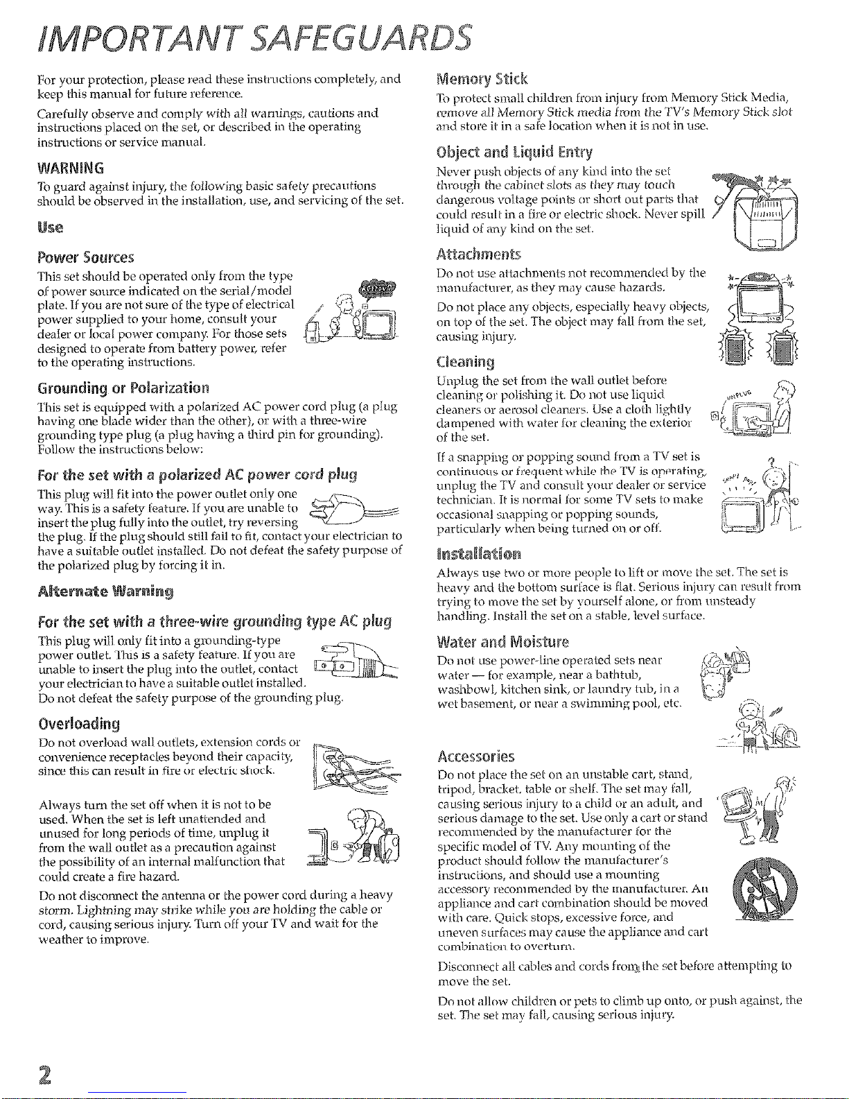
This set should bc operated only from the type
of power source indicated on the serial/model
‘3
plate. If you arc not sure of the type of electrical
/ q:
power supplied to your home, consult your
dealer or local power company. For those sets
designed to operdte from battery power, refer
Q&1
to the operating i~Mructions.
~~~~~~ifl~ or ~~~~~~~~~i~~~
This set is quipped with a polarized AC power cord plug (a plug
having one blade wider than the other), or with n three-wire
grounding type plug (a plug having a third pin for grounding).
lWow the instructionsbelow:
For t&e set aide a ~~~~~i~~
This plug will fit into the power
way. This is n safety leature. If you are
unable to
insert the plug fully into the outlet, try reversing
the plug. If the plug should slill fail to fit, contact 1
have a suitable outlet insta;lllecl. Do not defeat the safety purpose of
For the set wife a ~~~~~~wi type AC
This plug will only iit into a grm
g-tape
power outlet. This is a safety feature. If y&t are
7T\
unable to insert the plug into the outlet, contact
lIIqz~j~\~
your electrician to have a suitable outlet installed.
Do not defeat the safely purpose of the grounding plug.
~~~~~a~i~~
Do not overload wall outlets, extension cords or
convenience receptacles beyond their capacity,
b
jG
‘\-S
since this can result in fire or electric shock.
“-q=
<*s
Always turn the set off when it is not to be
used. When the set is left unattended and
unused for long periods of time, u~~plug it
from the wall outlet as d precaution against
2
-7 $)
the possibility of an internal malfunction that
could create a fire hazard.
Do not disconnect the antenna or the power cord during d heavy
storm. 1 ighining may strike while you are holding the cable or
cord, causing serious injury. Turn off your TV and wait for the
weather LO improve.
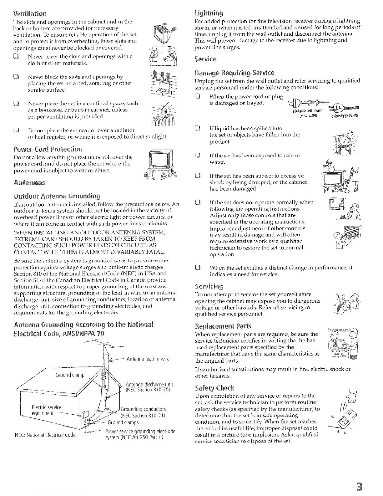
Antenna discharge unit
(NEC Section SIO-20)
NEC, Narional Flectiical Code
hver wwce grounding electrode
system (NEC Art 250 Part ti)
When the power cord 0f plug
is damaged or frayed.
If liquid has been spilled into
II the set has beeh subjjcct to excessive
shock by b&g dropped, or the cabinet
hds been damaged.
If the set does not operate noxmally when
following the operating ir~struclions.
Adjust only these controls that are
specified in the operating instnxtions.
Improper adjustment of other controls
tw~y result in damage and will ofteh
reqrtire extensive work by <I qwlified
tcchniciarr to restore the set to mxmal
operation.
Whw the set exhibits o cl istiwt change in pcrf~rma~~ce, it
indicates ‘a need for service.
ts are req<lired, be sure the
service technician certifies in writing that he has
used replacement parts specified by the
manufacturer that hwe the same characteristics as
the original parts.
Unautlwriacd substitutions may result in fire, electric shock or
other hazards.
Upon complelior~ of any service or repairs to the
set, ask the service technician to perform routine
safety checks (as specified by the mamrfacturer) to
determine that the set is in safe operating
condilion, axl to so certify. When the set reaches
the end of its useful life,
improper
disposal could
resttlt in a picture tube implosion. Ask a qualified
service technician to dispose of the set.

ga.....................~“*~.~“~~.”
...............................
7
Package Contents..
............................................................................
7
Features ............ ...................................................................
.......... .7
r~i~aY
.......................................................................................................
wer Cord .................................................................
ctars; .......................................................................
1
Front Panel .....................................................................................
10
Rear Panel .......................................................................................
12
~~~~~i~~~~
na
.................................
14
Cable or At ....................................................................
15
Cable and Antenna Only
.................................................................
16
Cable Box and Cable Only
...............................................................
IX
.....................................................................
20
ent ..............................................................
“21
.....................................................................
21
VCR and Cable.
...............................................................................
22
VCR and Cable l3ox .........................................................................
24
Two VCRs for Tape Editing
..............................................................
26
Satellite Receiver
..............................................................................
28
Satellite Receiver and VCR ...............................................................
30
IDVD Player with Component Video Connectors
32
................................
DVD Player with S VIDEO and Audio Connectors
............................
‘34
Camcorder
......................................................................................
35
................................................................................
36
...................................................................
37
L”ia;t ........................................................................
Using Auto Setup
...........................................................................
.38
es .......................................................................................
ens ....................................................................................
Panel ..................................................................................
Inside Panel .....................................................................................
42
P ra~~ii?
o&z ~~~~r~~ ............................................................
~Vj~~..” ..=. s...*.m..“...l” . . . . I . . . . . . . . . . . . . . . . . . . . . . . . . . . . . . . . . . . . . . . . . . . . ..~*~..~~..~~~..*~~.4~
TV..., . . . . .
. . . . . . . . . . . ““.“*““*“*.” . . . . ...” . . . . ***...“..* .,...... *.*sl.“..D..“.” . . . . n”*“...*.
“IcI.* . . . . . . . . ““..“l.l..*..l*~*..*“~“.~..~...*...~...~..”~~~ =.... . . . . . . . ...47
trolling Index .._.... .._................................ 4
. . . . . . . . . . . . . . . . . . . . . . . . . . . . . . . . . . . . . . . .
Displaying Twin Pictures .._................................................. 48
Factors Affecting Dual Picture Features ..,.......... 48
Activating
the Picture ,.... .._................... 49
Changing the Picture Size .._...._.........._....,...,..,...........,.................,., 50
~av~~j~~ ~~a~~~~~ ..“.l~~..l”“~l~l..~~~“~...~..“.~”.~ . ...=” . . . . *“e”ll . . . . . l...a*“*..““a” . . . . . ..a”7
Creating a IA of Favorite Channels ._..,.._.........,............................... 52
vorite Channels .._...._............................,........
.“l~~l,.~~~“X~.~l”*.,.~~~,~~~~~~~*~*~=”~.~.~~~”*~.~..~“~,”~~
ewver~...~“... I... ~.“~~.l*“~“~~“..l...~ . . . . e.“~“ll” . . . . . I
Supported
Image Types .._.,.._......................., .._..... 53
Unsupported Image Types .._....._. .._...._.._........................... ._.._.._._... 54
Inserting and Removing a Memory Stick .._...................................,, 55
Displaying the
Using the
Memory Stick Menu 56
Memory Stick Index 57
Using the Memory Stick Slideshow ..,,.._...._..._.........,........,....,...,...... 58
Changing the Memory Stick Setup Options ..__._.__._....__....... 58
Using the RoQLe Picture Scre
~~~~ E
.
mena ~j~~ Y te ~~~~~P~%...........................
53 .,,,..,,,.,.,...,...,...,,.,.....,......................,...............
This chapter describes the contents of the package in which the TV is
shipped and provides an overview of the features of your Wega TV.
The FD Trinitron Wega (pronounced VAY-GAH) is characterized by
outstanding contrast, uncompromising accuracy, and corner-tocorner detail.
You will recognize the superiority of Wega technology almost
immediately. The first thing you will probably notice is minimal glare
from the flat picture tube. This flat-screen technology improves
picture detaii without distortion, unlike conventional curved screens.
The FD Trinitron delivers outstanding image detail not only at the
screen center, but also at the corners - so you can enjoy a bright,
clear picture from any location in a room.
Along with your new Trinitron TV, the packing box contains a remote
control and two AA (R6) batteries. These items are all you need to set
up
and use the TV.
Some of the features that you will enjoy with your new TV include:
~~~~f~~~ti~~ VI: Unlike
Multifunction feature
replaces the signal’s NTSC waveform with the near-HD
equivalent, while doubling the number of vertical and horizontal
lines. This results in four times the density for quality sources,
such as DVD, satellite, and digital camcorders. The Video Menu
allows you to select interlaced, progressive, or (lineMotion”‘”
output. The DRC Palette option lets you customize the level of
detail (Reality) and smoothness (Clarity) to create up to three
custom palettes.
0
ex: ILets you preview and select programs from a
scrolling index of video pictures.
68
‘J
Li
16:9 is also referred to as
widescreen format.
Twin mwJTM:
TJsing the
Multi-Image
Driver (MIDX), Twin View
allows
you to watch two programs side by side, with the ability
to zoom in one picture. You can watch pictures from two different
sources (108Oi, 72Op, Mop, and 48Oi) simultaneously. (Only the
left Twin View window
can
display 108Oi, 72Oy, and 48Op
sources.)
@: Equalizes
volurr~e
levels so
there is consistent
output between programs ancl commercials.
eulogy S%icP lPic% re Viewers Allows
you to
view on your TV
screen digital images that are stored on Memory Stick media.
~~~e~% Video Ia1 uts: offers the best video yualif y for DV19
48Oi), and digital set-top box (I-KU 08Oi, 720~) connections.
e%a~~e~Tr*~
II Wideband video amplifier has a high bandwidth
frequency rating,
which allows ik to send more video
informalion
to tlte screen, resulting in finer
pictuuz quality
especially for I-ID
SOUlXXS.
*t~*~~~‘: Reverse 3-2 pulldown processing provides
1 picture quality for film-based sources (media originally
shot in 24 frames-per-second format).
ent: Vertical
Compression technology that
re resolution when playing “anamoryhic” or
idcscreen”
sources, including many DVDs.
trol: V-Chip technology allows parenks to block
younger viewers.
): Can accommodate a copyprotected digital connection (HDCP*) to other devices (such as
digital set-top boxes) that have compatible interfaces. The DVIHDTV input terminal is compliant with the EM-863 standard
and is not intended for use with personal computers.
---
..-..--..
*~igh~b~~dwidtb Digital Conlenl Protection
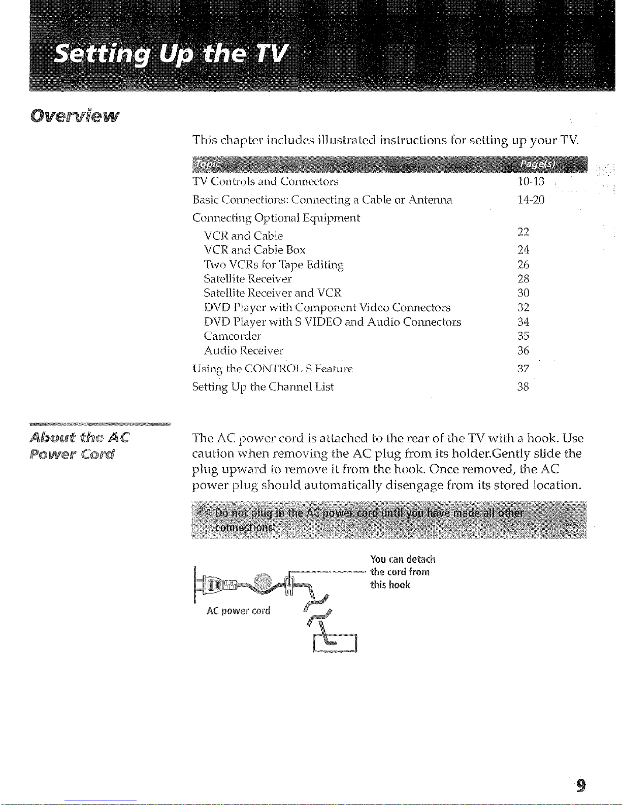
This chapter includes illustrated instructions for setting up your TV.
TV Controls and Connectors
10-13
Basic Connections: Connecting a Cable or Antenna
14-20
22
24
26
28
30
32
34
35
36
37
38
The AC power cord is attached to the rear of the TV with a hook. Use
mu
i-ion when removing the AC plug from its holder.GentIy slide the
plug upward to remove it from the hook, Once removed, the AC
power plug should automatically disengage from its stored location.

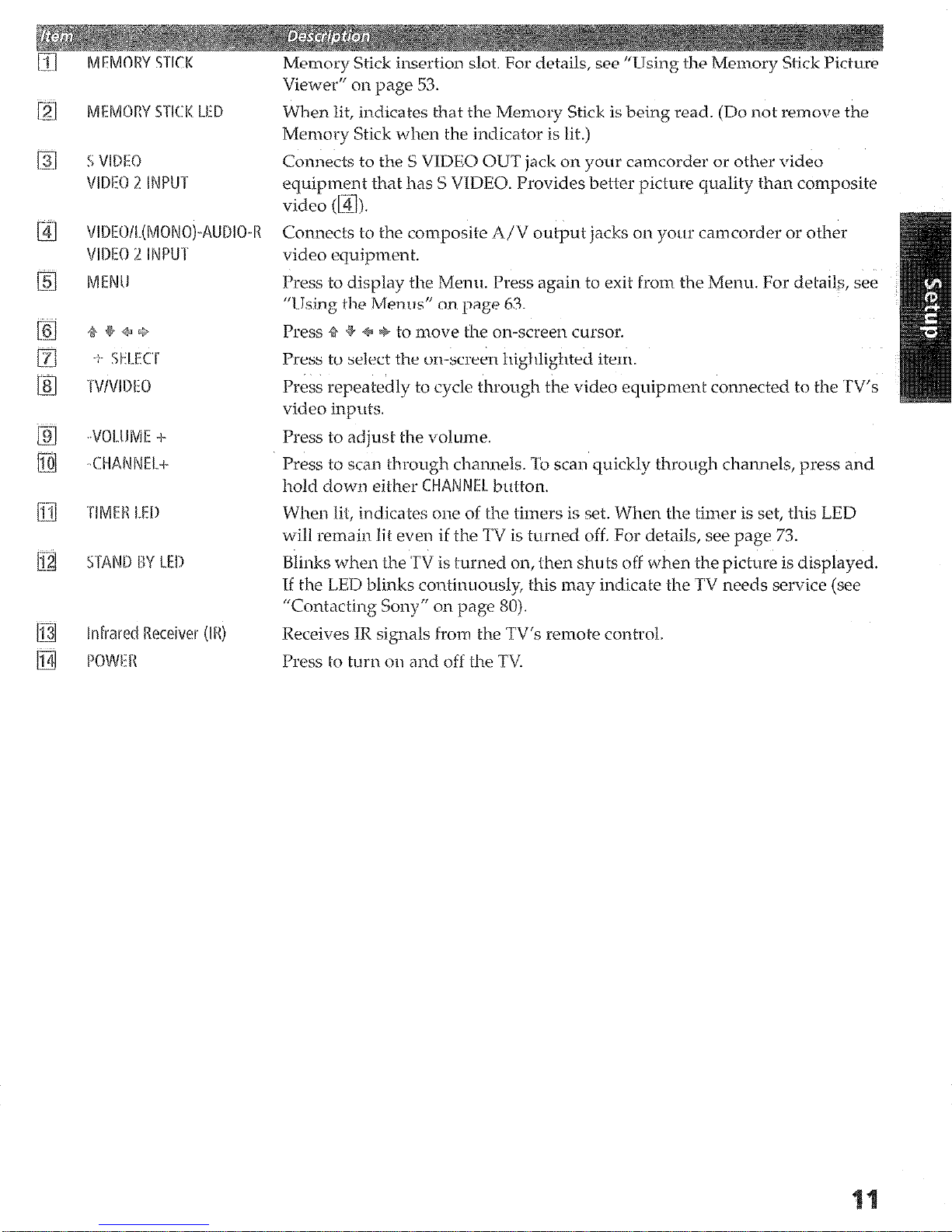
MEMORY STICK
Memory
Viewer” on page 53.
Stick insertion slot. For details, see “Using the Memory Stick Picture
._
iz
El
When lit, indicates that the Memory Stick is being read. (Do not remove the
Memory Stick wlten the indicator is lit.)
Connects to the S VIDEO OUT jack on your camcorder or other video
equipment that has S VXDEO. Provides better picture quality than composite
Connects
video equipment.
Press
Press to select the on-screen highlighted item.
Press repeatedly to cycle through
video inputs.
Press to adjust the volume.
Press to scan through channels. To scan quickly through channels, press and
hold down either CWANRIEL button.
When lil, indicates one of the timers is set. When the timer is set, this LED
will remain
Blinks when the TV
If the LED blinks continuously, this may indicate the TV needs service (see
“Contacting Sony” on page 80).
to the
to display the Menu. Press again to exit front the Menu. For
composite h/V
to move the
lit even
if the TV is turned off. For details, see page 73.
is
output
on-screen cursor.
turned on, then shuts off when the picture is displayed.
jacks on your camcorder or other
the
video eq+ment connected to tlte TV’s
details, see
Receives IR signals from the TV’s remote control.
Press I-o turn on and off the TV.

m AUS
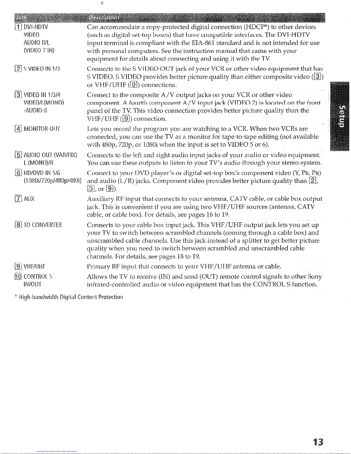
Can accommodate a copy-protected digital connection (HDCP”) to other devices
(such as digital set-fop boxes) that have compatible interfaces. The DVI-HDTV
input terminal is compliant with the EM-861 standard and is not intended for use
with personal computers. See the instruction manual that came with your
equipment for details about connecting and using it with the
TV.
Connects to the S VIDEO OUT jack of your VCR or other video equipment that has
S VIDEO. S VIDEO provides better picture quality than either composite video (m)
or VHF/UHF (m) connections.
Connect to
the
composite A/V output jacks on your VCR or other video
component. A
fourth
component A/V input jack (VIDEO 2) is located on the front
panel of the TV
This
video connection provides better picture quality than the
VHF/UHF (m) connection.
I.&s
you
record the
program
you are watching to a VCR. When two VCRs are
conected,
you
can use the TV as a monitor for tape-to-tape editing (not available
with 46Op, 72Op, or
‘108Oi when the input is set to VIDEO 5 or 6).
Connects to the left and right audio input jacks of your audio or video equipment.
You
can
LISA
these
outputs
to listen to your TV’s audio through your stereo system.
Connect to your DVD player’s or digital set-top box’s component video (Y, I%,
!?R)
(L/R) jacks. Component video provides better picture quality than a,
Auxiliary RF input that connects to
your
antenna, CATV cable, or cable box output
jack.
‘This
is convenient if you
are
using two VHF/UHF sources (antenua, CATV
cable, or cable box). For details, see pages 16 to 3 9.
Connects to
your
cable box input jack. This VHF/UHF output jack lets you set up
your TV
to switch between scrambled channels (coming through a cable box) and
unscrambled cable channels. Use this jack instead of a splitter to get better
picture
quality when
you need to
switch between scrambled
and
unscrambled cable
channels. For details, see pages IS to 19.
Primary RF input that connects to your VHF/UHF antenna or cable.
Allows the TV to receive (IN) and send (OLr7’) remote control signals to other Sony
infrared-controlled audio or video equipment that has the CONTROL S function.
* Hills-bandwidth Digiial Content Protection

The way in
which you will connect your TV varies, depending on
how your home receives a signal (cable, cable box, antenna) and
whether or not you plan to connect a VCR.
Li No cable box or
VCR
Cakde an
enna ~~~~
16
u No box or VCR
Ca’able Box and Cable
18
0 Cable box unscrambles only some
channels (usually premium channels)
0 NoVCR
U Cable box unscrambles all channels
L2 NoVCR
20
I.. See the connections described on pages 22 and 24.
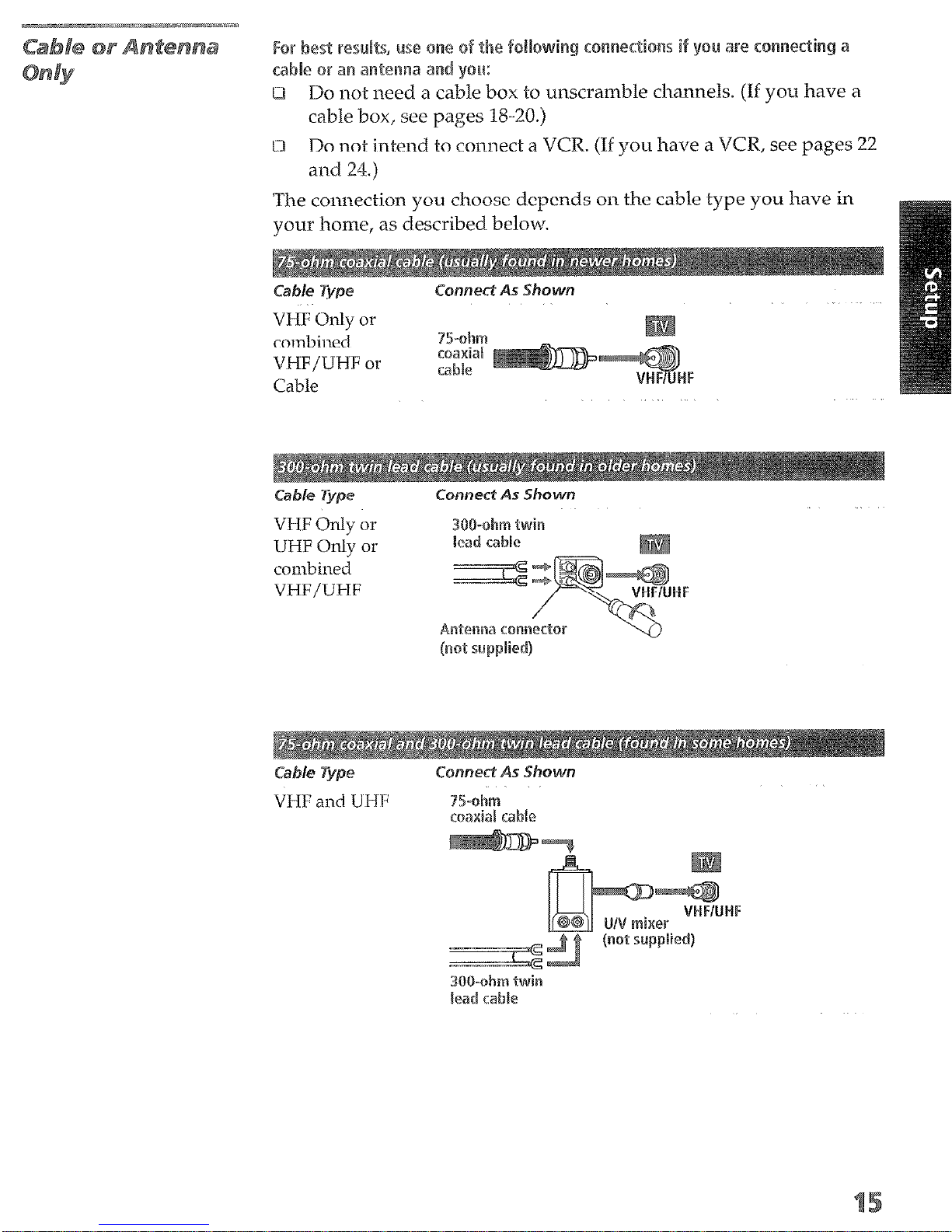
~~~~~~~~~~~ if you are ~~~~~~~~i~
r an a~~~~~a and you:
[;li Do not need a cable box to unscramble channels. (If you have a
cable box, see pages X3-20.)
w Do not intend to connect a VCR. (If you have a VCR, see pages 22
and 24.)
The connection you choose depends on the cable type you have in
your home, as described below.
VHF
Only or
combined
VHF/UHF or
Cable
UHF Onl+ or
combined
VHF/UHF
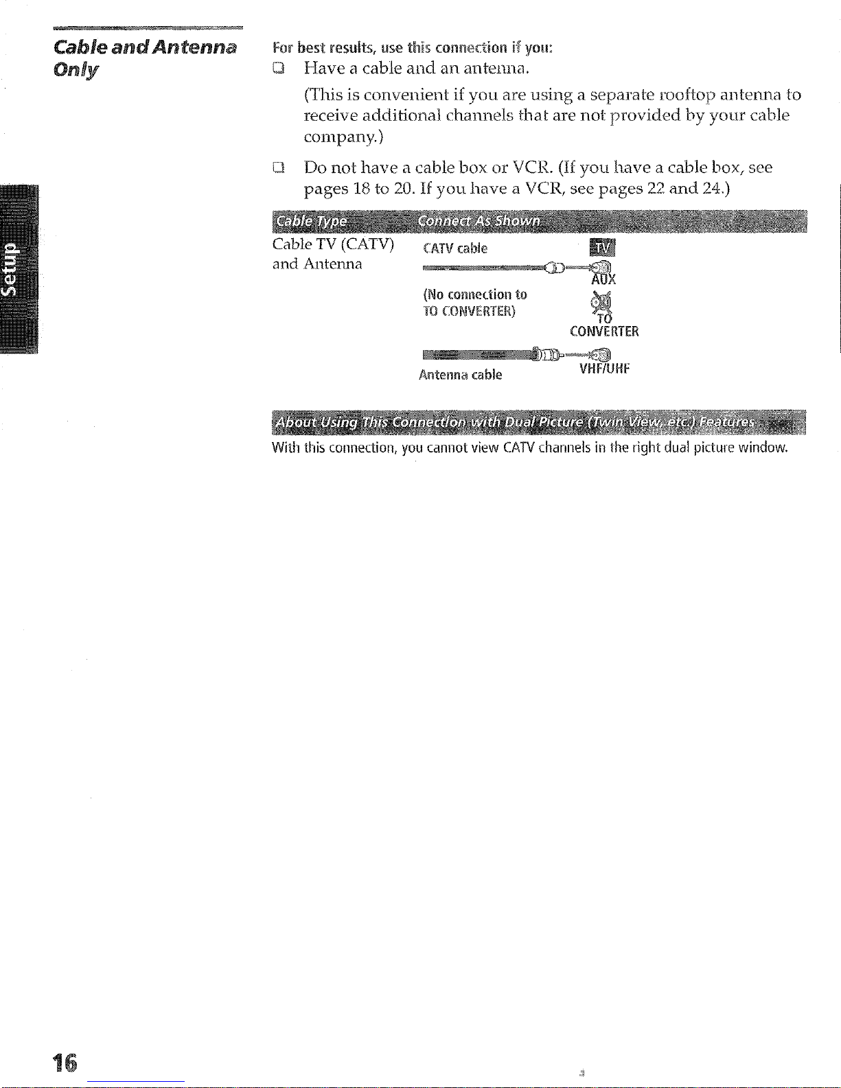
(This is convenient if you are using a separate rooftop
receive
additional channels
&at are not provided by
antenna to
your
cable
company.)
Q Do not have a cable box or VCK. (If you have a table box, see
pages 18 to 20. If you
With this connection, you cannot view CATV channels in the right dual picture window.
have a
VCR, see pages 22 and 24.)
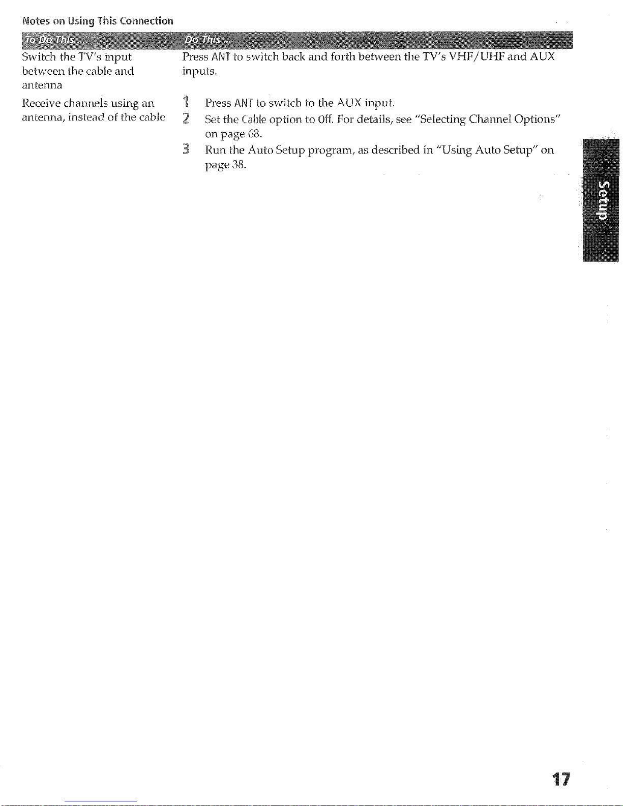
Switch the TV’s input Press ANT to switch back and forth between the TV’s VHF/UHF and ALJX
between the cable and
illpUtS.
antenna
Receive chanrlels using iln Press ANT to switch to the AUX input.
antenna, instead of t-he cable
2 Set the Cable option to Off.
For details, see “Selecting Channel Options”
cm page 68.
3 Run the Auto Setup program, as described in “Using Auto Setup” on
page 38.
est results, use this ~~~~e~~~~~ if:
0 Your cable company scrambles some channels, such as premium
channels (which requires you to use a cable box), but does not
scramble all channels.
0 You do not have a VCR. (If you have a
VCR, see pages 22 artd 24.)
blob this ~~~~e~~~~~ yeu can:
U Use the TV remote control to change channels coming through
the cable box to the TV’s AUX input jack. (You must first program
the remote control for your specific cable box; see “Programming
the Remote Control” on page 43.)
12 Use
With this connection, you can use all the dual picture features for unscrambled channels
coming directly into the TV’s VI-WUMF input jack.
l-iowever, you can use only some of the dual picture features for channels coming
through the cable box to the TV’s AUX input jack. For example, when you switch the TV’s
input to AUX -to select the cable box input---the picture displays only in the left
window. For example, if you turn on Twin View, you can watch cable channels coming
into the VHF/UHF jack in the right window, but you cannot swap the pictures between
the left and right windows.
the
TV remote control to change channels coming directly
into the TV’s VEKF/UHF input. (The TV’s tuner provides a better
signal than the cable box.)
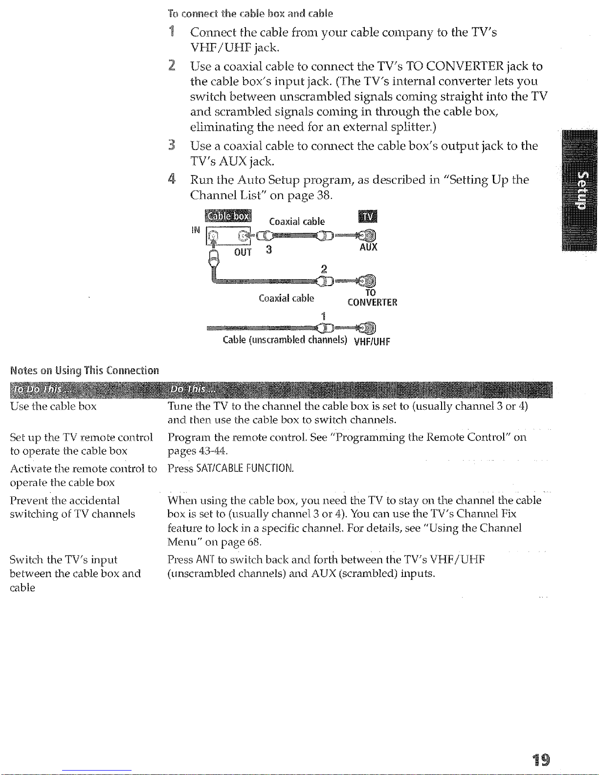
1 Connect the cable from your cable company to the TV’s
Vhttps://manualmachine.com/U~~~ jack.
Use a coaxial cable to connect the TV’s TO CONVERTER jack to
the cable box’s input jack. (The TV’s internal converter lets you
switch be&Teen unscrambled signals coming straight into the TV
and scrambled signals coming in through the cable box,
eliminating the need for an external splitter.)
Use a coaxial cable to connect the cable box’s output jack to the
TV’s ALJX jack.
Run the Auto Setup program, as described in “Setting Uy the
Channel List” on page 38.
Set up the TV remote control
to operate the cable box
Activate the remote control to
operak-e the cable box
Prevent the accidental
switching of TV channels
Switch the TV’s
between the cable box and
cable
input
--Tune the TV to
and then use the cable box to switch channels.
Program the remote control. See
the channel
the cable box is set to (usually channel 3 or 4) Use the cable box
“Programming the Remote Control” on
pages 43-44.
Press S~~~~~BL~ ~~~~rl~~~.
When using the cable box, you need the TV to stay on the channel the cable
box is set to
feature to lock in a specific channel. For details, see “Using
(usually
channel 3 or 4). You can use the
TV’s
Channel Fix
the
Channel
Menu” on page 68.
Press ANT to switch back and forth between the ‘TV’s VHF/UHF
(unscrambled channels) ‘and
AUX
(scrambled) inputs.
the cable box to the TV’s Vhttps://manualmachine.com/U~~~ jack. (Uou must first
program the remote control For your’specific cable box.)
this connection, all channels come into the TV through your cable box and only one-
unscrambled signal is sent to the T!/, so you cannot use the dual picture featutes,. If
some of your channels are scrambled, but others are not, consider using the “Cable Box
and Cable” connection on page 18 instead.
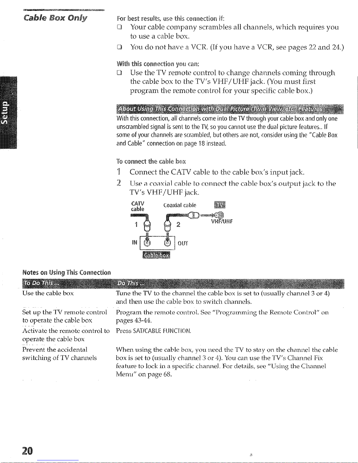
To ~~~~ec~ tile cable box
? Connect the CA’FJ cable to the
2 Use a coaxial cable to connect the cable box’s output jack to the
TV’s VHF/UHF jack.
Use the cable box
Set
up
the ‘TV remote control Program the remote control. See “Programming the Remote Control” on
to operate the cable box pages 43-44.
Activate the renlote control to
operate the cable box
Tune the TV to the channel the cable box is set to (usually channel 3 or 4)
and then
use
Press SATICN%.E ~~Jt~~~~~~~,
cable bo>c’s input jack
the cable box to switch channels.
Prevent the accidental
switching of TV channels
When using the cable box,
box is set to
feature to lock in a specific channel. For details, see “Lising the Channel
Menu” on page 68.
(usually
you need
the TV to stay on the channel the cable
channel 3 or 4). You can use the TV’s Channd Fix
Use the directions in this section to connect the following optional
equipment:
VCR and Cable
DVD Player with S VIDEO and Audio
Con1-lectors
Canxxxlcr
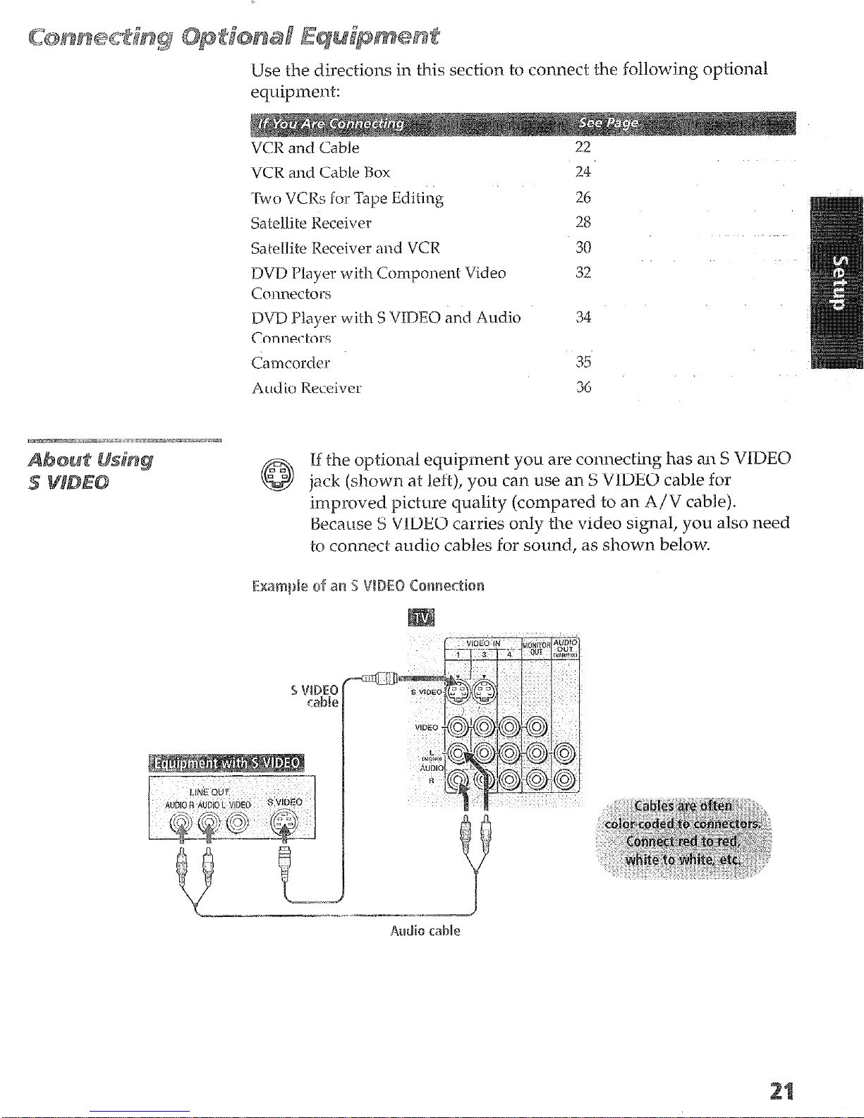
If the optional equipment you are connecting has an S VIDEO
jack (shown at left), you can use an S VIDEO cable for
improved picture quality (compared to an A/V cable).
Becanse S
VIDEO carries only the video signal, you also need
to connect audio cables for sound, as shown below.
22
24
26
28
30
32
34
35
36
This ~~~~~~~~~~
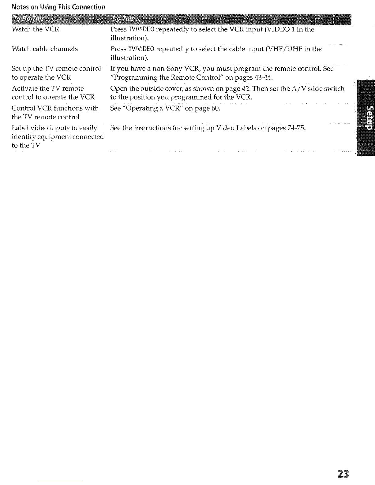
Watch the VCR
Press ~V/~i~E~ repeatedly to select the VCR
input
(VIDEO 1 in the
illustration).
Watch cable channels
Press ~V/Vl~E~ repeatedly to select the cable input (VHF/UHF in the
illustration).
Set up i-he ‘TV
remote control
If you have a non-Sony VCR,
you
must program the remote control. See
to operate the VCR “Programming the Remote Control” on pages 43-44.
Activate the
control to operate the VCR to the position you programmed
Control VCR functions with
the
TV remote
Label video inputs to easily
TV
control
remote
Open the
See “Operating a VCR”
outside
cover,
as shown on page 42. Then set the A/V slide switch
on
page 60.
for the
VCR.
See the instructions for setting up Video Labels
on pages 74-75.
identify equipment connected
to the
TV
For best ~~S~~~S, we this C~~~~~~~~~~~~ is:
u Your cable company scrambles some channels,
channels (which requires you tn use a cable box),
scramble all channels.
such as
but does not
premium
IS connection,
you
can use a
Use the TV remote control to change channels coming through
the cable box.
(You must
first program the
remote control for
your specific cable box; see “Programming the Remote Control”
on page 43.)
L,! Use the TV remote control to change channels coming directly
into the ‘TV’s VHF/UHF jack, (The TV’s tuner provides a better
signal than the cable box.)
3 Record channels coming through the cable box and channels
coming directly into the TV
d cable box, you need.
hi& is a small, inexpensive device that you can
purchase at your local electronics store.
0 Three coaxial cables.
21 One A/V
cable or one S VJDECP
cable with audio cables.
Connect the CATV cable to the single
(input)
jack of the splitter.
Use a coaxial cable to connect one of the splitter’s two output
jacks to the TV‘s VHP;/UFF jack.
Use a coaxial cable to conned: the splitter’s other
the
cable
box’s input jack.
o~~tp-nt
jack to
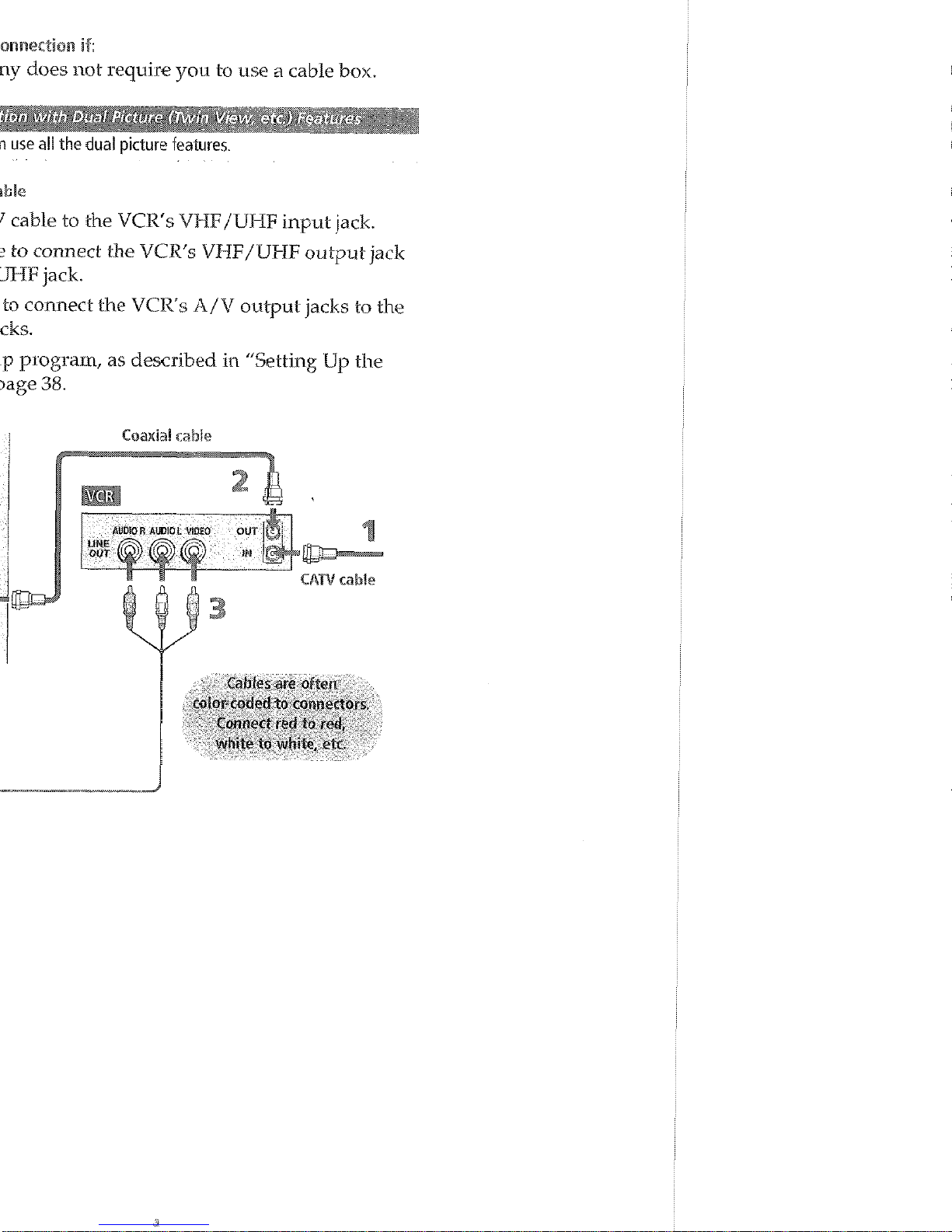
Use a coaxial cable to connect the cable box’s output jack to the
VCR’s RF input jack.
Use an A/V cable to connect the VCR’s A/V output jacks to the
TV’s A/V input jacks.
RLIII the Auto Setup program, as described in
“Setting
IJp the
Channel List” on page 38.
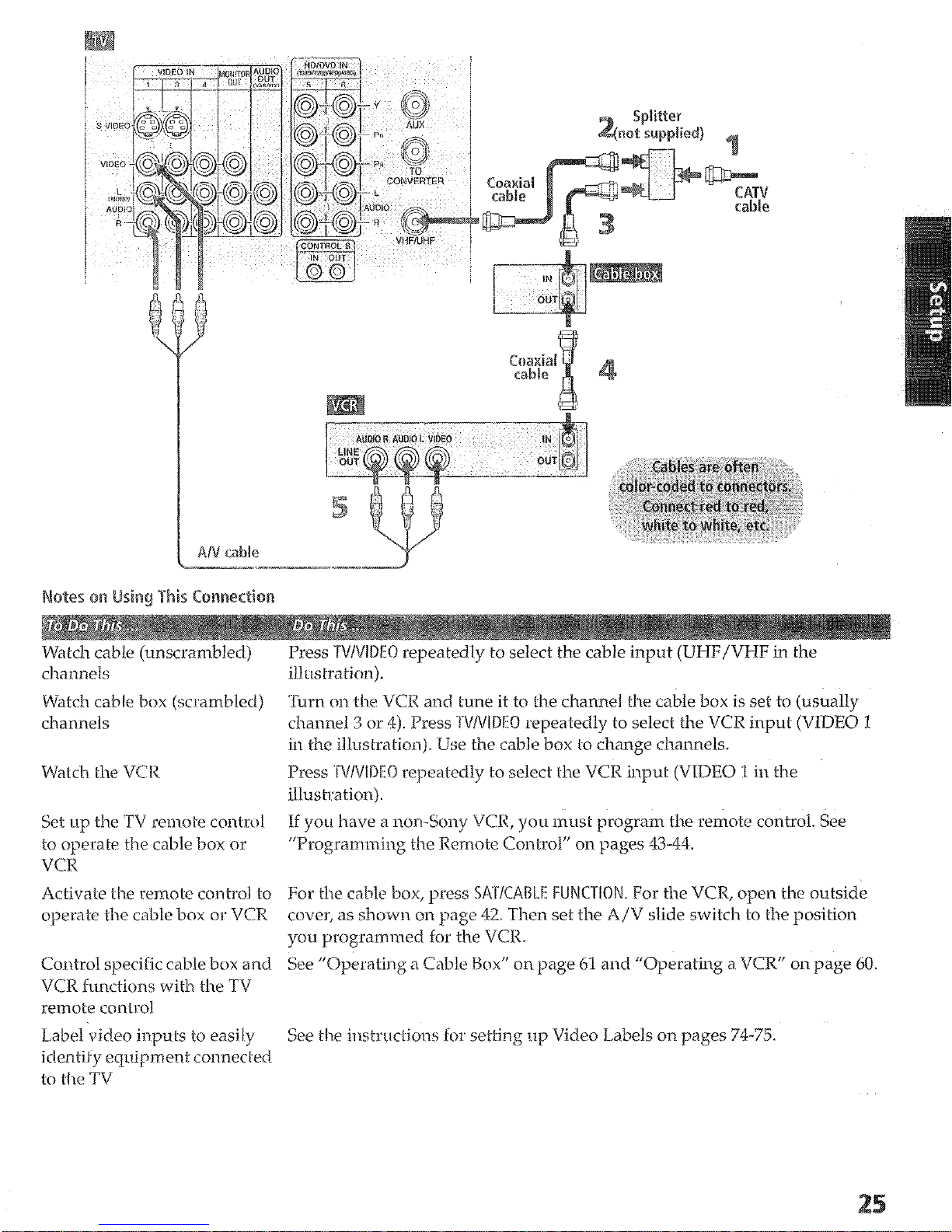
Wat& cable (unscrambled)
channels
Press ~V/~l~~~ repeatedly to select the cable input (UIHF/VHF in the
illLMratiori).
Watch cable box (scrambled)
channels
Set LIP the
TV remote contrr,l
to operate the cable box or
VCR
Activate the rernoto control to
operate the cable box or VCR
Coritrol specific cable box and
VCR fur&ions with the TV
remote control
L,abel video inputs to easily
identify equipment connecl-ed
to the TV
‘finm on the VCR and tune it to the channel the cable box is set to (usually
channel 3 or 4). Press .~V/Vi~~~ repeatedly to select the VCR input (VIDEO 1
in the illustration). Use the
cable
box to change channels.
Press ‘rV/~l~~~~ repeatedly to select the VCR input (VIDEO 1 in the
illustration).
If you have a non-Sony
VU?,
you must ~9rogram the remote control. See
“Programming the Remote Control” on pages 43-44.
For tlte cable box, press ~~r~~~~~~ ~UN~TI~N. For the VCR, open the outside
cover, as shown on
page
42. Then set the A/V slide switch to the position
you programmed for the VCR.
See “Operating a Cable Xsox” on page 61 and “Operating a VCR” on page 60.
See the instritctions for setting up Video Labels on pages 74-75.
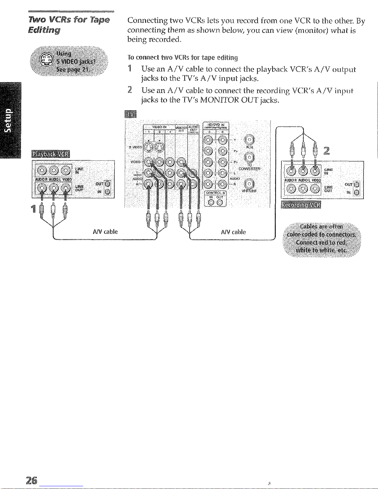
Connecting two VCRs lets you record from one VCR to the other. By
connectiing them a5 shown below, you can view (monitos) what is
being recorded.
~~~~~~~
Use an A/V cable to connect the playback VCR’s A/V output
jacks to the TV’s A/V input jacks.
Use an A/V cable to connect the recording VCR’s A/V input
jacks to the TV’s M~~~~~~ OUT jacks.
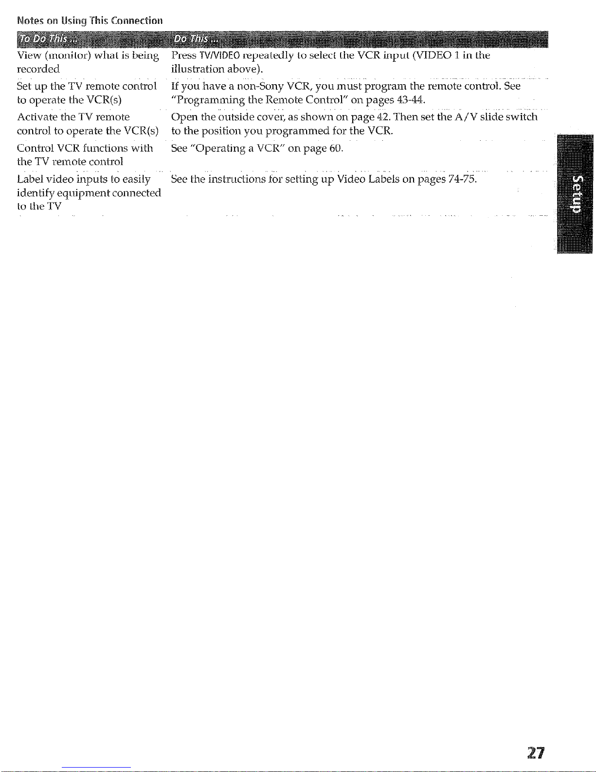
View (monitor) what is being Press https://manualmachine.com/~I~~~ repeatedly to select the VCR input (VIDEO 1 in the
recorded illustration above).
Set
~tp
the TV remote co&O1 If you have a non-§ony VCR, you m&t’&ogram the remote control. See.
lo operate the VCR(s)
“Programming the Remote Control“ on pages 43-44.
Ac L-ivate the TV remote
control to operate the VCR(s)
Control VCR functions with
the TV remote control
Label video inputs to easily
identify eqrripment connected
to the TV
Open the outside cover, as shown on page 42. Then set the A/V slide switch
tdthe position you programmed for the VCR.
See “Operating a VCR” on page 60.
See the instructions for setting up Video Labels on pages 74-75.
 Loading...