

Sony FD Trinitron KV-32FQ70B, FD Trinitron KV-32FQ70K, FD Trinitron KV-32FQ70U, FD Trinitron KV-32FQ70E Service Manual
- 1 -
SERVICE MANUAL
AE-6B
CHASSIS
MODEL
COMMANDER DEST CHASSIS NO.
KV-32FQ70B
RM-938 FR SCC-Q83N-A
KV-32FQ70E
RM-9 38 ESP SCC- Q81Q-A
MODEL
COMMANDER DEST CHASSIS NO.
KV-32FQ70
RM-938
KV-32FQ70K
RM-938 OIRT SCC-Q82J-A
KV-32FQ70U
RM-938 UK SCC-Q84N-A
- 7 -
egasseMrorrE
DEL
edoC
rorreoN00
devreseR10
)noitcetorPtnerruCrevO(PCO20
noitcetorPegatloVrevO30
cnySlacitreVoN40
norewoptarorrERKI50
norewoptawolsenilatadro/dnakcolcsubCII60
norewoptaegdelwonkcasubCIIonMVN70
noitcetorPlatnoziroH80
norewoptaegdelwonkcaonrenuT90
rorrErossecorPdnuoS01
devreseR11
rorrEetarnacS21
rorrECAD31
rorrEdnekcaB41
rorrEecnegrevnoCcimanyD51
rorrEPIP61
AE-6B SELF DIAGNOSTIC SOFTWARE
The identification of errors within the AE-6B chassis is triggered in one of two ways :- 1: Busy or 2: Device failure to respond to IIC. In the
event of one of these situations arising the software will first try to release the bus if busy (Failure to do so will report with a continuous
flashing LED) and then communicate with each device in turn to establish if a device is faulty. If a device is found to be faulty the relevant
device number will be displayed through the LED (Series of flashes which must be counted) See table 1, non fatal errors are reported using this
method.
Each time the software detects an error it is stored within the NVM. See Table 2.
Table 1
How to enter into Table 2
1. Turn on the main power switch of the TV set.
2. Program Remote Commander for Operation in Service
Mode. [See Page 22].
3. Press ‘VIDEO’ ‘VIDEO’ > ‘MENU’ on the Remote
Commander.
4. Using the Remote Commander, Scroll to the ‘Error Menu’
item using the down arrow key, then press the right arrow
key.
5. The following table will be displayed indicating the error
count.
Table 2
Note: To clear the error count data press ‘80’ on the Remote
commander.
UNEMRORRE
20E
30E
40E
50E
60E
70E
80E
90E
01E
11E
21E
31E
41E
51E
61E
EMITGNIKROW
SRUOH
SETUNIM
PCO
PVO
CNYSV
RKI
CII
MVN
TORPH
RENUT
PDNUOS
ETARNACS
CAD
DNEKCAB
NOCNYD
PIP
)552,0(
)552,0(
)552,0(
)552,0(
)552,0(
)552,0(
)552,0(
)552,0(
)552,0(
)552,0(
)552,0(
)552,0(
)552,0(
)552,0(
)552,0(
0
0
0
0
0
0
0
0
0
0
0
0
0
0
0
41
7
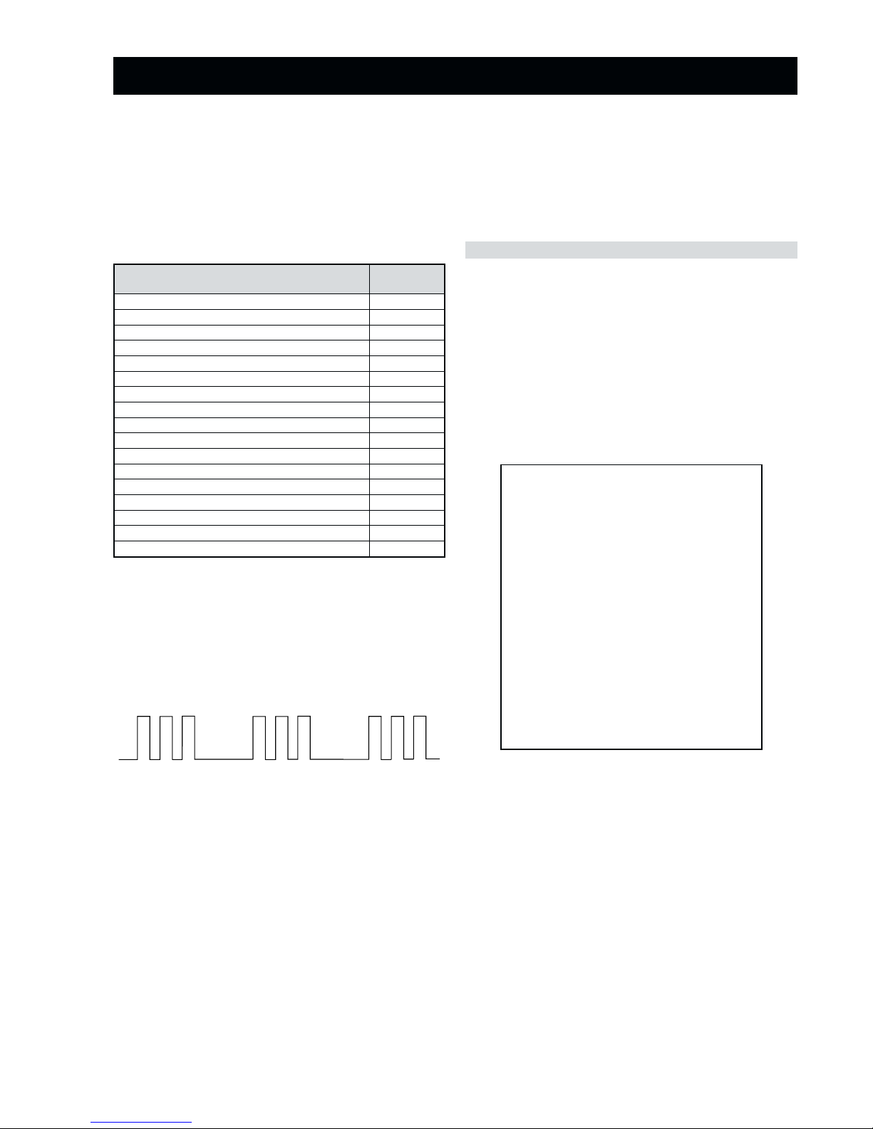
Flash Timing Example : e.g. error number 3
StBy LED
ON ON ON
OFF
OFF
- 22 -
4-1. Electrical Adjustments
Service adjustments to this model can be performed using the
supplied remote Commander RM-938.
SECTION 4 CIRCUIT ADJUSTMENTS
3. Press 99999. All three LED’s should light.
The remote commander is now set to Service Mode.
4. To return the remote commander to normal operation mode
repeat steps 1. and 2. then press 00000. All three LED’s
should light.
The remote commander is now set to normal mode.
Programming the Remote Commander for
Operation in Service Mode
Setting the TV into Service Mode
1. Program the remote commander for operation in Service
Mode as described above.
2. Turn on the TV main power switch.
3. Press the video standby button on the remote
commander twice.
‘TT ’ will appear in the upper right corner of the screen.
Other status information will also be displayed.
4. Press ‘MENU’ on the remote commander to obtain the
following menu on the screen.
5. Move to the corresponding adjustment item using the
up or down arrow buttons on the Remote Commander.
6. Press the right arrow button to enter into the required menu item.
7. Press the ‘Menu’ button on the Remote Commander to quit the
Service Mode when all adjustments have been completed.
Note :
· After carrying out the service adjustments, to prevent the
customer accessing the ‘Service Menu’ switch the TV set
OFF and then ON.
·
yrtemoeG
amaronaP
ecivreS
etarnacS
CAD
PiP
dnuoS
tsujdaFI
uneMrorrE
)2002naJ(12.2vediWB6EA
h61h20atadyrotcaF
G1143PSM:eciveDPSM
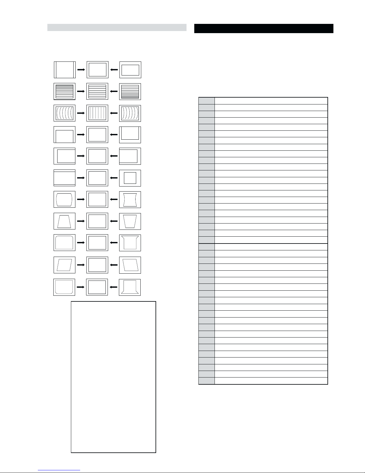
YRTEMOEG
HTLBA
EDOMLBA
LBAP
EZISV
NOITISOPV
PMOCV
NILV
NOITCERROCS
EZISH
PMANIP
NIPRENROCPU
NIPM
NIPRENROCOL
MUIZEPART
NOITISOPH
WOBCFA
ELGNACFA
KLBTFEL
KLBTHGIR
TCEPSAV
1MITBKA
2MITBKA
RKI
GNH
GNV
)3,0(
)3,0(
)51,0(
)36,0(
)36,0(
)3,0(
)51,0(
)51,0(
)36,0(
)36,0(
)36,0(
)3,0(
)36,0(
)51,0(
)36,0(
)51,0(
)51,0(
)36,0(
)36,0(
)36,0(
)3,0(
)1,0(
1
0
0
0
0
51
53
33
1
7
7
44
23
92
2
92
2
04
8
9
43
71
74
2
0
AMARONAP
HHTDIWROH
LHTDIWROH
HSOPROH
LSOPROH
HPILPPAN
LPILPPAN
HCSOPCSH
LCSOPCSH
LEDNALB
NELNALB
LOPNALB
H1GESH
L1GESH
H2GESH
L2GESH
H3GESH
L3GESH
H4GESH
L4GESH
HOCNIH
LOCNIH
H1CNIH
L1CNIH
H2CNIH
L2CNIH
H3CNIH
L3CNIH
H4CNIH
L4CNIH
)7,0(
)552,0(
)7,0(
)552,0(
)7,0(
)721,0(
)51,0(
)552,0(
)552,0(
)552,0(
)1,0(
)7,0(
)552,0(
)7,0(
)552,0(
)7,0(
)552,0(
)7,0(
)552,0(
)1,0(
)552,0(
)1,0(
)552,0(
)1,0(
)552,0(
)1,0(
)552,0(
)1,0(
)552,0(
1
071
0
51
1
26
8
151
31
702
0
0
69
0
291
0
422
1
46
0
04
0
02
0
0
1
632
1
612
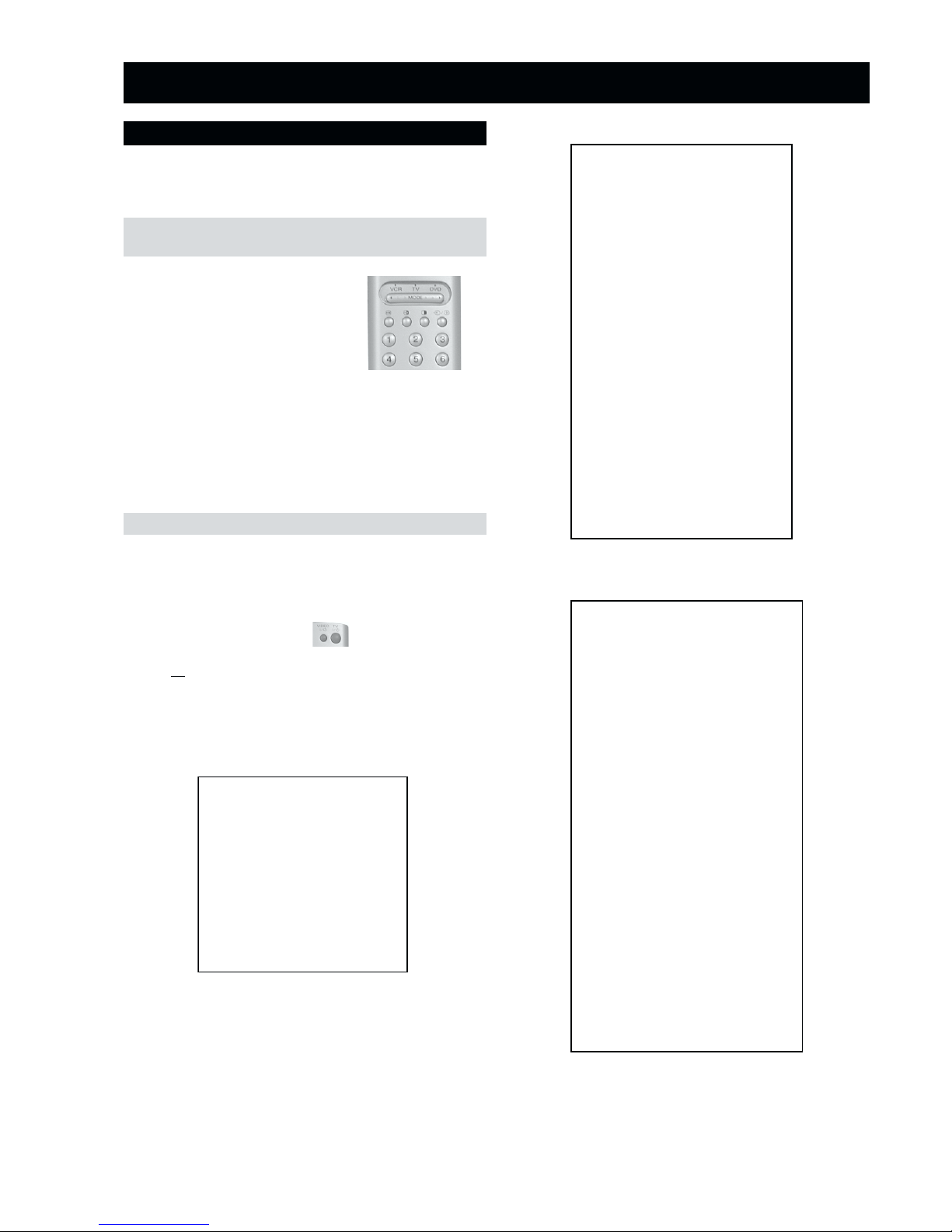
1. Press the VCR/TV/DVD button until the
TV LED lights.
2. Press and hold the yellow button for
approx. 5 seconds until the TV LED
flashes quickly.
- 23 -
Sub Colour Adjustment
1. Receive a PAL colour bar signal.
2. Connect an oscilloscope to Pin 6 of CN7001 [A Board].
3. Program the Remote Commander for operation in Service Mode.
[ See Page 22 ].
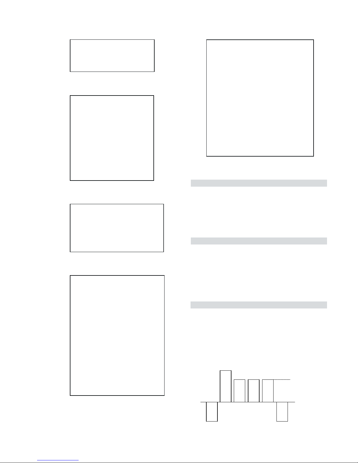
4. Adjust the ‘Sub Colour’ [ Using ‘VIDEO’ ‘VIDEO’ ‘12’ ] so
that the Cyan, Magenta and Blue colour bars are of equal levels
as indicated below.
Same Level
B-Out Waveform
Sub Brightness Adjustment
1. Input a Monoscope pattern.
2. Program the Remote Commander for operation in Service Mode.
[ See Page 22 ].
3. Press ‘VIDEO’ ‘VIDEO’ 13 on the Remote Commander.
4. Adjust the ‘Sub-Brightness’ data so that there is barely a
difference between the 0 IRE and 10 IRE signal levels.
1. Input a video signal that contains a small 100% white area on a
black background.
2. Connect an digital voltmeter to Pin 10 of J7376 [C Board].
3. Program the Remote Commander for operation in Service Mode.
[ See Page 22 ].
4. Adjust the Sub-Contrast [ Using ‘VIDEO’ ‘VIDEO’ ‘11’ ] to
obtain a voltage of 105 +/- 5V.
Sub Contrast Adjustment
UNEMRORRE
20E
30E
40E
50E
60E
70E
80E
90E
01E
11E
21E
31E
41E
51E
61E
EMITGNIKROW
SRUOH
SETUNIM
PCO
PVO
CNYSV
RKI
CII
MVN
TORPH
RENUT
PDNUOS
ETARNACS
CAD
DNEKCAB
NOCNYD
PIP
)552,0(
)552,0(
)552,0(
)552,0(
)552,0(
)552,0(
)552,0(
)552,0(
)552,0(
)552,0(
)552,0(
)552,0(
)552,0(
)552,0(
)552,0(
0
0
0
0
0
0
0
0
0
0
0
0
0
0
0
41
7
TSUJDAFI
etumotuA
niaGoiduA
gnitaGL
1
0
0
DNUOS
N-M
D-M
S-M
M-S
M-D
M-N
EBB
1B
2B
3B
4B
5B
LWS
FWS
DACMACIN
rorrEMACIN
oeretS
)115,0(
)1-,821-(
)721+,0+(
)721+,0+(
)1-,821-(
)3201,0(
)86+,0+(
)69+,69-(
)69+,69-(
)69+,69-(
)69+,69-(
)69+,69-(
)0+,821-(
)04+,5+(
)7402,0(
)721+,821-(
10001
002
02-
02+
01+
01-
694
82+
0+
0+
0+
0+
0+
0+
03+
0
0+
sutatS0110000000
CAD
GIFNOC
TNOCNIPM
NILH
PARTH
LIOC.TOR
HPSUCOHP
)552,0(
)552,0(
)552,0(
)552,0(
)552,0(
00000000
69
38
721
031
09
ECIVRES
LOCBUS
EUHBUS
PRAHSBUS
THGIRBBUS
TNOCBUS
EVIRD-R
EVIRD-G
EVIRD-B
FFOTUCR
FFOTUCG
FFOTUCB
TXTrB
DSOrB
)36,0(
)36,0(
)36,0(
)36,0(
)51,0(
)36,0(
)36,0(
)36,0(
)36,0(
)36,0(
)36,0(
)51,0(
)51,0(
jdA
13
03
31
21
05
jdA
jdA
82
42
64
7
01
- 24 -
1. Program the Remote Commander for operation in Service Mode.
[ See Page 22 ] and enter into the ‘Geometry’ service menu.
2. Select and adjust each item in order to obtain the optimum image.
Deflection System Adjustment
V SIZE
V LIN
AFC BOW
V POSITION
H POSITION
H SIZE
PIN AMP
TRAPEZIUM
UP CORNER PIN
AFC ANGLE
LO CORNER PIN
YRTEMOEG
HTLBA
EDOMLBA
LBAP
EZISV
NOITISOPV
PMOCV
NILV
NOITCERROCS
EZISH
PMANIP
NIPRENROCPU
NIPM
NIPRENROCOL
MUIZEPART
NOITISOPH
WOBCFA
ELGNACFA
KLBTFEL
KLBTHGIR
TCEPSAV
1MITBKA
2MITBKA
RKI
GNH
GNV
)3,0(
)3,0(
)51,0(
)36,0(
)36,0(
)3,0(
)51,0(
)51,0(
)36,0(
)36,0(
)36,0(
)3,0(
)36,0(
)51,0(
)36,0(
)51,0(
)51,0(
)36,0(
)36,0(
)36,0(
)3,0(
)1,0(
1
0
0
0
0
51
53
33
1
7
7
44
23
92
2
92
2
04
8
9
43
71
74
2
0
Test Mode 2 is available by rogramming the Remote Commander for
operation in Service Mode [ As shown on Page 22 ] then pressing the
‘VIDEO’ button twice, OSD ‘TT’ appears. The functions described
below are available by selecting the two numbers. To release the ‘Test
mode 2’, press 00, 10, 20 ... or switch the TV set into Stand-by
mode.
4-2. TEST MODE 2:
72
RKEDAnoitanitseD
82
RKEDAnoitanitseD
13
elbasiD/elbanEffotuhSotuA
63
tsetNO/FFO)MV(noitaludoMyticoleV
14
MVNesilaitini-eR
34
dnuosAlauDtceleS
44
dnuosBlauDtceleS
54
dnuosonoMtceleS
64
dnuosoeretStceleS
84
nigrivnonsaMVNteS
94
nigrivsaMVNteS
35
elbasiD/elbanEnoitaludomrevOMF
55
)SPLA/YNOS(noitcelesrenuT
95
stracS2roPIP+stracS3ledoMtceleS
86
)melborpN(erusaemretnuoc62XelbasiD/elbanE
37
)47.6/5.6(metsys2K/DnotiewZelbanE
47
)47.5/5.6(metsys3K/DnotiewZelbanE
87
thgirllufecnalaB
97
tfelllufecnalaB
78
tsetsyeklacoL
99
unememiTgnikroWdnarorrEyalpsiD
00
ffoedom'TT'
10
mumixamerutciP
20
muminimerutciP
30
%53otemuloVenohpdaeh/rekaepsteS
40
%05otemuloVenohpdaeh/rekaepsteS
50
%56otemuloVenohpdaeh/rekaepsteS
60
%08otemuloVenohpdaeh/rekaepsteS
70
edomgniegA
80
noitidnoCgnippihS
11
tnemtsujdaerutcipbuS
21
tnemtsujdaruolocbuS
31
tnemtsujdassenthgirBbuS
41
tnemtsujdanoitisoPHtxeT
51
tseTlioCnoitatoR
61
%05levelerutciP
91
elbasiD/elbanEedoMyrotcaF
12
RKEDAnoitanitseD
22
LBnoitanitseD
32
RKEDAnoitanitseD
42
UnoitanitseD
52
RKEDAnoitanitseD
62
LBnoitanitseD
ABCDE F
G
H I J K L M N
1
2
3
4
5
6
7
8
9
10
11
- 29 -
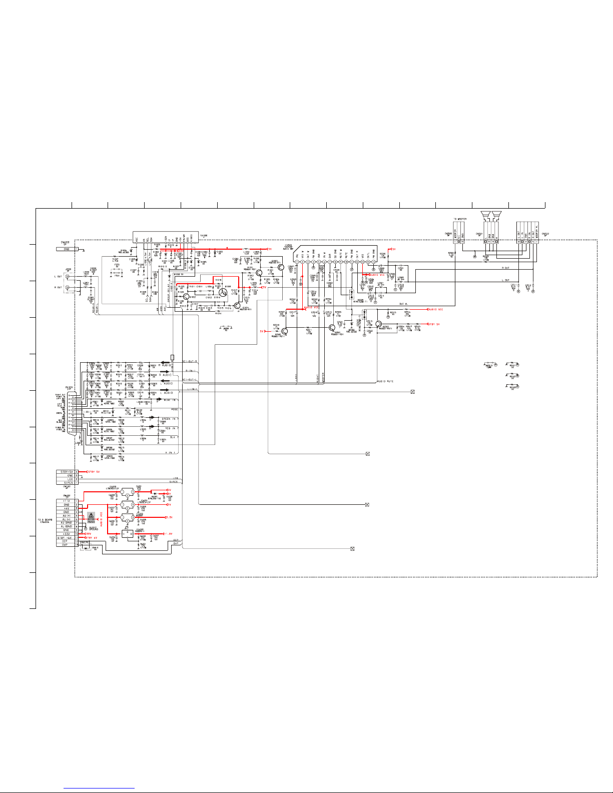
~ A Board Schematic Diagram [ Tuner, Audio Amp & Scart Connector ] Page 1/6 ~
F
2
5
3
4
1
MICRO
A 2/6
3/6
6/6
SCART
AUDIO
A 2/6
VIDEO
A 2/6
3/6
5/6
MUTE
A 2/6
A
1/6 TUNER, AUDIO AMP & SCART CONNECTOR
COMPONENTS MARKED AS XX ARE NOT FITTED ON THIS MODEL
A..-32FQ70
xx
xx
xx
xx
xx
xxxxxx
xx
xx
xx
xx
xx
0
xx
TO H1 BOARD
CN2910
TO F1 BOARD
CN0981
+5V
 Loading...