

Sony FD Trinitron KV-29SE10B,FD Trinitron KV-29SE10E,FD Trinitron KV-29SE10K Service Manual
- 1 -
SERVICE MANUAL
BX-1L
CHASSIS
MODEL
COMMANDER DEST CHASSIS NO.
KV-29SE10B
RM-EA005 F R SCC-V53A-A
KV-29SE10E
RM-EA005 ESP SCC-V51A-A
MODEL
COMMANDER DEST CHASSIS NO.
KV-29SE10
RM-EA005
KV-29SE10K
RM-EA005 OIRT SCC-V52A-A

- 2 -
TABLE OF CONTENTS
Section Title Page Section Title Page
Caution .................... 3
Specifications .................... 4
Connectors .................... 5
Self Diagnostic Software .................... 6
1. GENERAL
Switching On the TV and
Automatically Tuning .................... 8
Introducing and Using the Menu
System .................... 10
Teletext .................... 11
Connecting Additional Equipment ............... 12
Lifting the TV Set .................... 12
Specifications .................... 13
Troubleshooting .................... 13
2. DISASSEMBLY
2-1. Rear Cover Removal .................... 14
2-2. Chassis Removal & Refitting .................... 14
2-3. Service Position .................... 14
2-4. Wire Dressing .................... 14
2-5. Picture Tube Removal .................... 15
3. SET-UP ADJUSTMENTS
3-1. Beam Landing .................... 16
3-2. Convergence .................... 17
3-3. Focus Adjustment .................... 19
3-4. Screen (G2), White Balance .................... 19
4. CIRCUIT ADJUSTMENTS
4-1. Electrical Adjustments .................... 20
4-2. Test Mode 2 .................... 30
5. DIAGRAMS
5-1. Block Diagrams (1) .................... 31
Block Diagrams (2) .................... 32
5-2. Circuit Board Location .................... 32
5-3. Schematic Diagrams and
Printed Wiring Boards .................... 32
* A Board Schematic .................... 33
* A Board PWB .................... 39
* C Board Schematic .................... 40
* C Board PWB .................... 41
* H2 Board Schematic .................... 42
* H2 Board PWB .................... 41
5-4. Semiconductors .................... 43
6. EXPLODED VIEWS
6-1. Chassis .................... 44
6-2. Picture Tube .................... 45
7. ELECTRICAL PARTS LIST .................... 46
CAUTION
SHORT CIRCUIT THE ANODE OF THE PICTURE TUBE AND THE
ANODE CAP TO THE METAL CHASSIS, CRT SHIELD, OR THE
CARBON PAINTED ON THE CRT, AFTER REMOVAL OF THE
ANODE CAP.
WARNING !!
AN ISOLATION TRANSFORMER SHOULD BE USED DURING
ANY SERVICE WORK TO AVOID POSSIBLE SHOCK HAZARD
DUE TO LIVE CHASSIS, THE CHASSIS OF THIS RECEIVER IS
DIRECTLY CONNECTED TO THE POWER LINE.
SAFETY-RELATED COMPONENT WARNING !!
COMPONENTS IDENTIFIED BY SHADING AND MARKED
ON
THE SCHEMATIC DIAGRAMS, EXPLODED VIEWS AND IN THE
PARTS LIST ARE CRITICAL FOR SAFE OPERATION. REPLACE
THESE COMPONENTS WITH SONY PARTS WHOSE PART
NUMBERS APPEAR AS SHOWN IN THIS MANUAL OR IN
SUPPLEMENTS PUBLISHED BY SONY.
ATTENTION
APRES AVOIR DECONNECTE LE CAP DE’LANODE,
COURT-CIRCUITER L’ANODE DU TUBE CATHODIQUE ET
CELUI DE L’ANODE DU CAP AU CHASSIS METALLIQUE DE
L’APPAREIL, OU AU COUCHE DE CARBONE PEINTE SUR LE
TUBE CATHODIQUE OU AU BLINDAGE DU TUBE
CATHODIQUE.
ATTENTION !!
AFIN D’EVITER TOUT RISQUE D’ELECTROCUTION
PROVENANT D’UN CHÁSSIS SOUS TENTION, UN
TRANSFORMATEUR D’ISOLEMENT DOIT ETRE UTILISÈ LORS
DE TOUT DÈPANNAGE LE CHÁSSIS DE CE RÈCEPTEUR EST
DIRECTMENT RACCORDÈ Á L’ALIMENTATION SECTEUR.
ATTENTION AUX COMPOSANTS RELATIFS Á
LA SECURITÈ!!
LES COMPOSANTS IDENTIFIÈS PAR UNE TRAME ET PAR UNE
MARQUE SUR LES SCHÈMAS DE PRINCIPE, LES VUES
EXPLOSÈES ET LES LISTES DE PIECES SONT D’UNE IMPOR-
TANCE CRITIQUE POUR LA SÈCURITÈ DU FONCTIONNEMENT,
NE LES REMPLACER QUE PAR DES COMPSANTS SONY DONT
LE NUMÈRO DE PIÈCE EST INDIQUÈ DANS LE PRÈSENT
MANUEL OU DANS DES SUPPLÈMENTS PUBLIÈS PAR SONY.
- 3 -
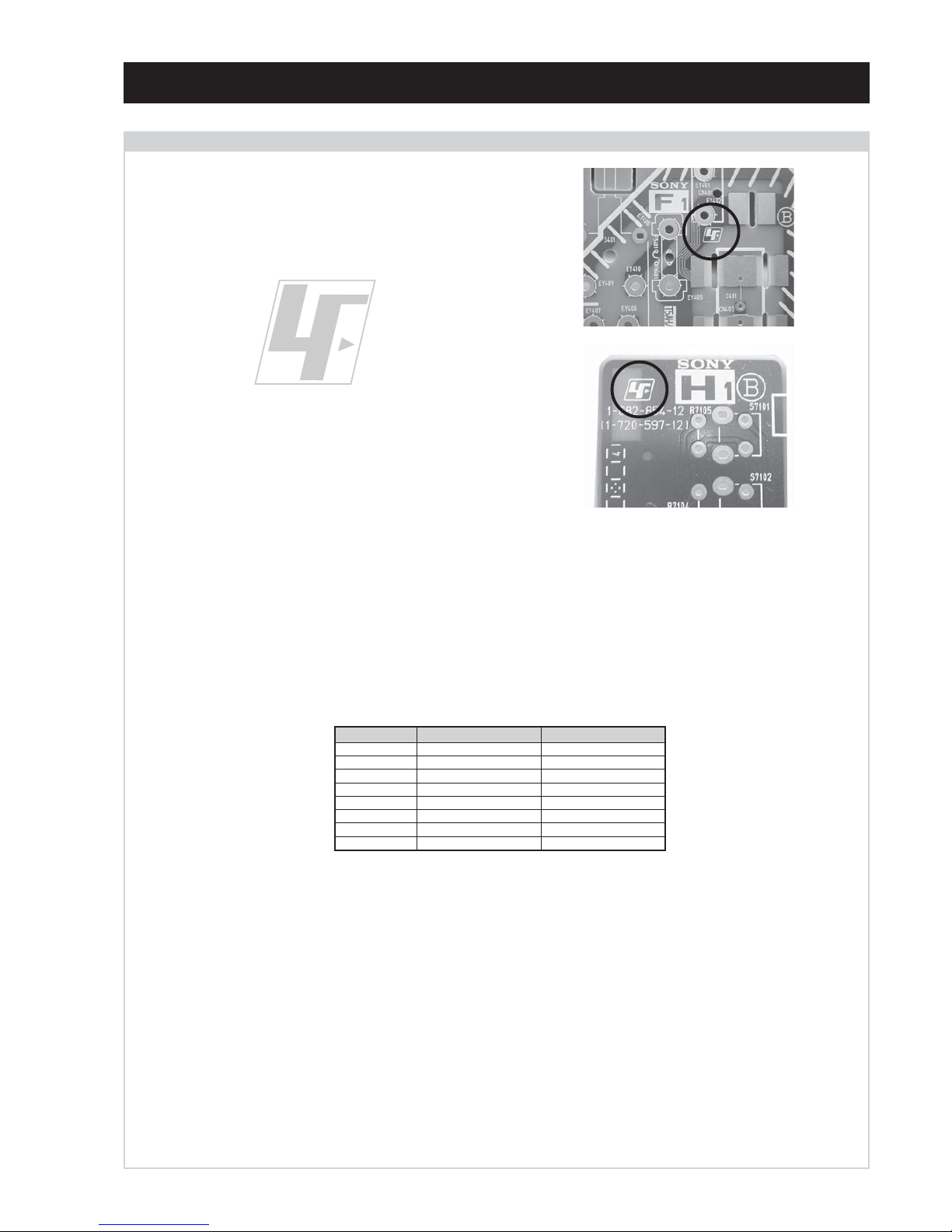
The circuit boards used in these models have been processed using
Lead Free Solder. The boards are identified by the LF logo located
close to the board designation e.g. F1, H1 etc [ see examples ]. The
servicing of these boards requires special precautions to be taken as
outlined below.
CAUTION
Lead Free Soldered Boards
example 1
example 2
It is strongly recommended to use Lead Free Solder material in order to guarantee optimal quality of new solder joints. Lead Free Solder is
available under the following part numbers :
Due to the higher melting point of Lead Free Solder the soldering iron tip temperature needs to be set to 370 degrees centigrade. This requires
soldering equipment capable of accurate temperature control coupled with a good heat recovery characteristics.
For more information on the use of Lead Free Solder, please refer to http://www.sony-training.com
rebmuntraP retemaiD skrameR
91-500-046-7mm3.0gK52.0
02-500-046-7mm4.0gK05.0
12-500-046-7mm5.0gK05.0
22-500-046-7mm6.0gK52.0
32-500-046-7mm8.0gK00.1
42-500-046-7mm0.1gK00.1
52-500-046-7mm2.1gK00.1
62-500-046-7mm6.1gK00.1
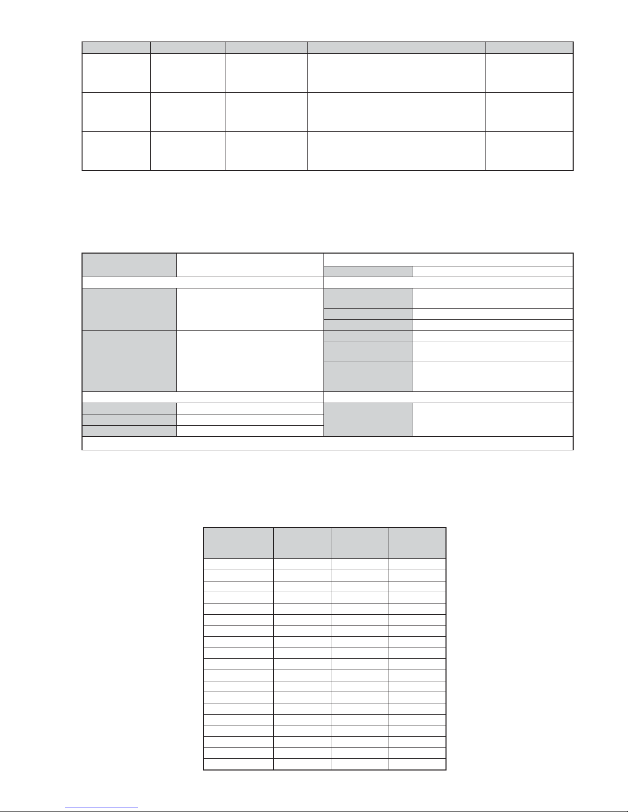
- 4 -
LEDOMMETI metsySnoisiveleT metsySoeretS egarevoClennahC metsySroloC
BL,I,K/D,H/G/B
MACIN/NAMREG
oeretS
Q-B,01F-20F,30S-10S,21R-1R,21E-2E:FHV
96R-12R,96B-12B,96F-12F,96E-12E:FHU
02S-10S:VTELBAC
14S-12S:REPYH
MACES,LAP
85.3CSTN,34.4CSTN
)NIOEDIV(
EK/D,H/G/B
MACIN/NAMREG
oeretS
,30S-10S,21R-1R,21E-2E:FHV
96R-12R,96E-12E:FHU
02S-10S:VTELBAC
14S-12S:REPYH
MACES,LAP
85.3CSTN,34.4CSTN
)NIOEDIV(
KK/D,H/G/B
MACIN/NAMREG
oeretS
30S-10S,21R-1R,21E-2E:FHV
96R-12R,96E-12E:FHU
02S-10S:VTELBAC
14S-12S:REPYH
MACES,LAP
85.3CSTN,34.4CSTN
)NIOEDIV(
emaNledoM
metI
B01ES92-VK E01ES92-VK K01ES92-VK
bmoClaPNONONO
PAPFFOFFOFFO
ytiroirPBGRNONONO
xoBrefooWFFOFFOFFO
1tracSNONONO
2tracSNONONO
3tracSFFOFFOFFO
)3(nitnorFNONONO
4tracSFFOFFOFFO
rotcejorPFFOFFOFFO
G/BmroNNONONO
ImroNNOFFOFFO
K/DmroNNONONO
SUAmroNFFOFFOFFO
LmroNNOFFOFFO
TASmroNFFOFFOFFO
MmroNFFOFFOFFO
txeteleTNONONO
oeretSmaciNNONONO
ebuTerutciP
:EDIWnortinirTDFyalpsiDtalF
)sehcni92(mc37xorppA
tuptuodnuoS
rekaepstfeLdnathgiR)SMR(W6x2)rewoPcisuM(W21x2
]RAER[slanimreTtuptuO/tupnI snoitacificepSlareneG
rotcennocoruEnip-12:1
)dradnatsCELENEC(
.slangisoediVdnaoiduArofstupnI
.BGRrofstupnI
.slangisoiduAdnaoediVVTfostuptuO
stnemeriuqeRrewoPV042-022
noitpmusnoCrewoPW1</W031
snoisnemiDmm125x595x677xorppA
rotcennocoruEnip-12:2
)dradnatsCELENEC(
.slangisoediVdnaoiduArofstupnI
.oediVSrofstupnI
.slangisoiduAdnaoediVVTfostuptuO
)elbatceles(
ecafretnIkniltramS
thgieWgk54xorppA
seirosseccAdeilppuS
)1(rednammoCetomeR500AE-MR
)2(yrettab6RdetangisedCEI
serutaeFrehtO
,remiTnO,remiTpeelS,txeteleT
noitcetedotuAmetsySVT
]TNORF[slanimreTtuptuO/tupnI lortnoCderarfnI:metsySlortnoCetomeR
kcajenohpdaeHkcajinimoerets
stnemeriuqerrewoP
cdV3
noitangisedCEIseirettab2
)AAezis(6R
stupnioiduAskcajonohp
stupnioediVskcajonohp
.ecitontuohtiwegnahcottcejbuserasnoitacificepsdnangiseD
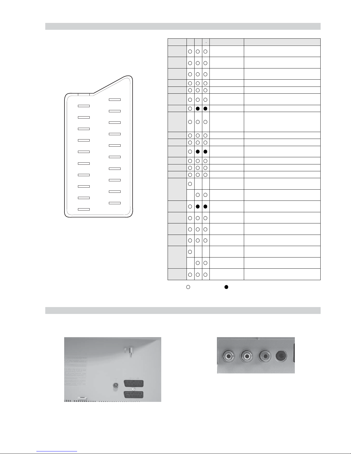
- 5 -
Connected Not Connected (open) * at 20Hz - 20kHz
Pin No 1 2 4 Signal Signal level
1 Audio output B
(right)
Standard level : 0.5V rms
Output impedence : Less than 1kohm*
2
Audio input B
(right)
Standard level : 0.5V rms
Output impedence : More than 10kohm*
3
Audio output A
(left)
Standard level : 0.5V rms
Output impedence : Less than 1kohm*
4 Ground (audio)
5 Ground (blue)
6 Audio input A
(left)
Standard level : 0.5V rms
Output impedence : More than 10kohm*
7 Blue input 0.7 +/- 3dB, 75 ohms positive
8 Function select
(AV control)
High state (9.5-12V) : Part mode
Low state (0-2V) : TV mode
Input impedence : More than 10K ohms
Input capacitance : Less than 2nF
9 Ground (green)
10 Open
11 Green Green signal : 0.7 +/- 3dB, 75 ohms,
positive
12 Open
13 Ground (red)
14 Ground (blanking)
15
_ _ Red input 0.7 +/- 3dB, 75 ohms, positive
_ (S signal Chroma
input)
0.3 +/- 3dB, 75 ohms, positive
16 Blanking input
(Ys signal)
High state (1-3V) Low state (0-0.4V)
Input impedence : 75 ohms
17 Ground (video
output)
18 Ground (video
input)
19 Video output 1V +/- 3dB, 75ohms, positive sync 0.3V
(-3+10dB)
20
_ _ Video input 1V +/- 3dB, 75ohms, positive sync 0.3V
(-3+10dB)
_ Video input
Y (S signal)
1V +/- 3dB, 75ohms, positive sync 0.3V
(-3+10dB)
21 Common ground
(plug, shield)
21 pin connector
19
17
15
13
11
9
7
5
3
1
20
18
16
14
12
10
8
6
4
2
21
Rear Connection Panel Front Connection Panel
3
- 6 -
BX-1L SELF DIAGNOSTIC SOFTWARE
BX-1L chassis TV’s contain a self diagnosis function. In the event of an error occurring, the STANDBY LED indicator will automatically begin
to flash. The number of times the STANDBY LED indicator flashes translates to a probable source of the problem. If an error symptom cannot
be reproduced, the remote commander can be used to review the failure occurrence data stored in memory to reveal past problems and how often
these problems occur.
1. DIAGNOSTIC TEST INDICATORS
When an error occurs, the STANDBY indicator will flash a set number of times to indicate the possible cause of the problem. If there is more
than one error, the indicator will identify the first of the problem areas.
The result for all of the following diagnosis items are displayed on screen. No error has occured if the screen displays a “0”.
* If a+B overcurrent is detected, then the vertical deflection is detected simultaneously. The symptom that is diagnosed first by the micro
controller is displayed on the screen.
** Refer to Screen (G2) Adjustment on page 19.
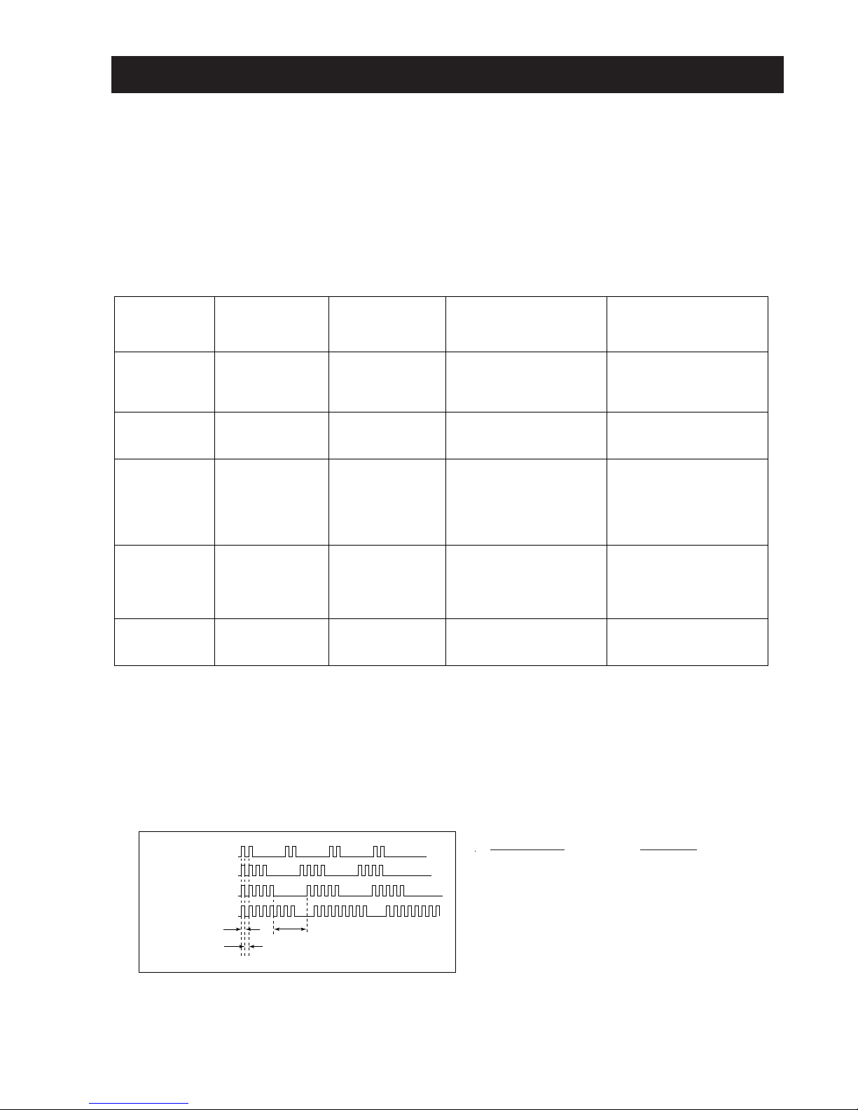
2. DISPLAY OF STANDBY INDICATOR FLASH COUNT
V
Lamp OFF 3 sec
Lamp ON 300ms
Lamp OFF 300ms
Diagnostic Item Flash Count
+B Overcurrent 2 flashes
V-Protect 4 flashes
IK (AKB) 5 flashes
HV Protect 8 flashes
* One flash count is not used for self-diagnosis.
Diagnosis
Item
Description
Power does
not turn on
+B overcurrent
(OCP)*
V-Protect
IK (AKB)
HV Protect
No. of timer
STANDBY (1)
indicator flashes
Does not light
2 times
4 times
5 times
8 times
Self-Diagnostic
display/
Diagnosis result
–
2:0
or
2:1 ~ 255
4:0
or
4:1 ~ 255
5:0
or
5:1 ~ 255
8:0
or
8:1 ~ 255
Probable Cause
Location
• Power cord is not plugged
in.
• Fuse is burned out (F4601)
A board.
• H OUT (Q511) is shorted.
(A board)
• IC751 is shorted. (C board)
• +13V is not supplied.
(A board)
• IC503 is faulty. (A board)
• Video OUT (IC751) is
faulty. (C board)
• IC001 is faulty. (A board)
• Screen (G2) is improperly
adjusted.**
• IC604 faulty.
• IC602 faulty.
Detected
Symptoms
• Power does not come on.
• No power is supplied on
TV.
• AC Power supply is faulty.
• Power does not come on.
• Load on power line is
shorted.
• Has entered standby state
after horizontal raster.
• Vertical deflection pulse is
stopped.
• Power line is shorted or
power supply is shorted.
• No raster is generated.
• CRT Cathode current
detection reference pulse
output is small.
• No power supply to CRT
ANODE.
• No RASTER is generated.
- 7 -
3. STOPPING THE STANDBY INDICATOR FLASH
Turn off the power switch on the TV to stop the STANDBY indicator from flashing.
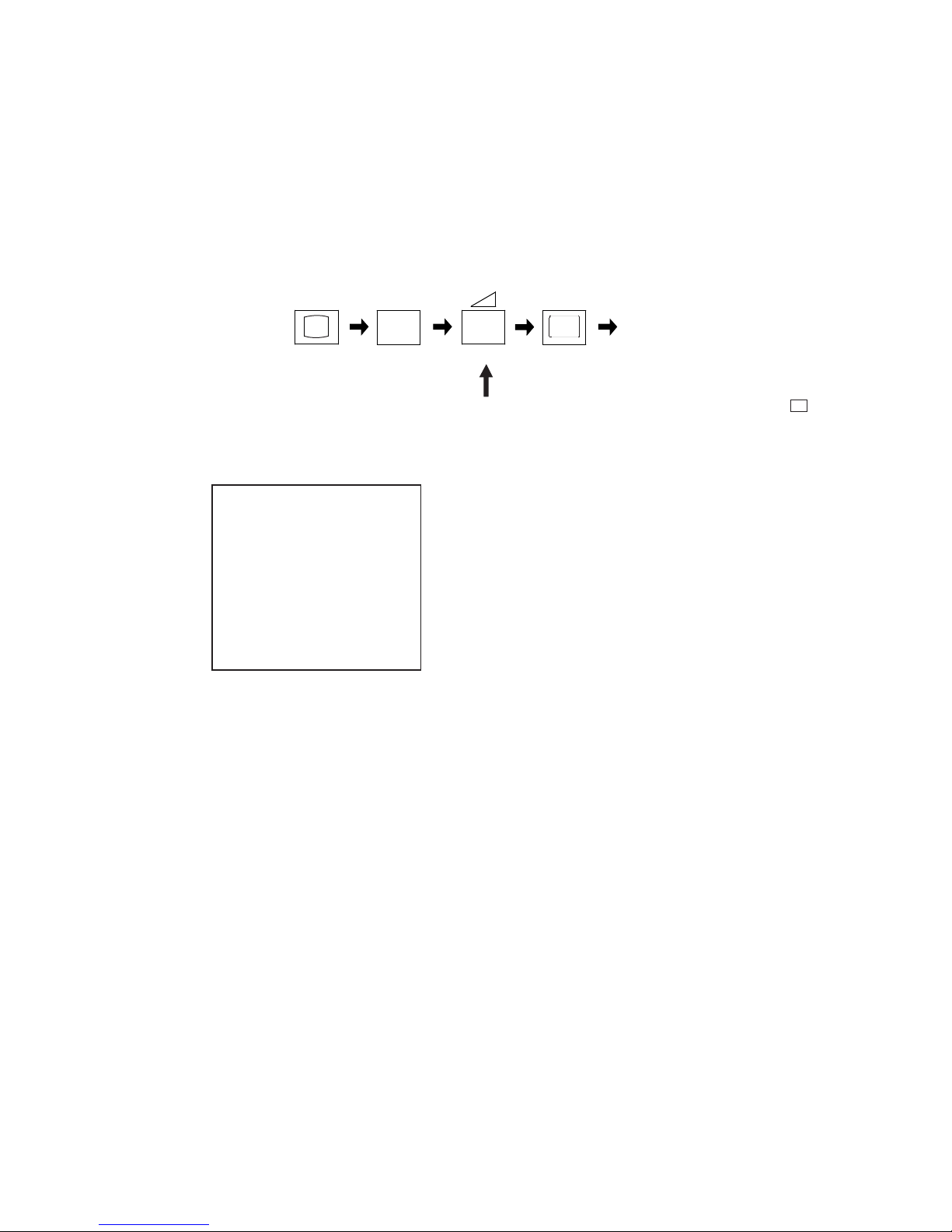
4. SELF-DIAGNOSTIC SCREEN DISPLAY
For errors with symptoms such as “power sometimes shuts off” or “screen sometimes goes off” that cannot be confirmed, it is possible to bring
up past occurrences of failure on the screen for confirmation.
To bring up the screen test
The following screen will be displayed indicating the error count.
i+
5
+
(ON SCREEN (DIGIT 5) (VOLUME +) (TV)
DISPLAY)
In standby mode, press buttons on the remote commander sequentially in rapid sucession as shown below:
Note that this differs from entering the service mode (volume + )
UNEMRORRE
:2
:3
:4
:5
:8
:101
EMITGNIKROW
SRUOH
SETUNIM
0
A/N
0
1
0
A/N
241
23
Numeral “0” means that no fault was detected.
Numeral “1” means the number of a fault occurrence (1 ~ 255).
To clear the error display count press “8” then “0” on the remote commander.
To exit the self-diagnostic screen, turn off the power switch on the TV set.
- 8 -
8
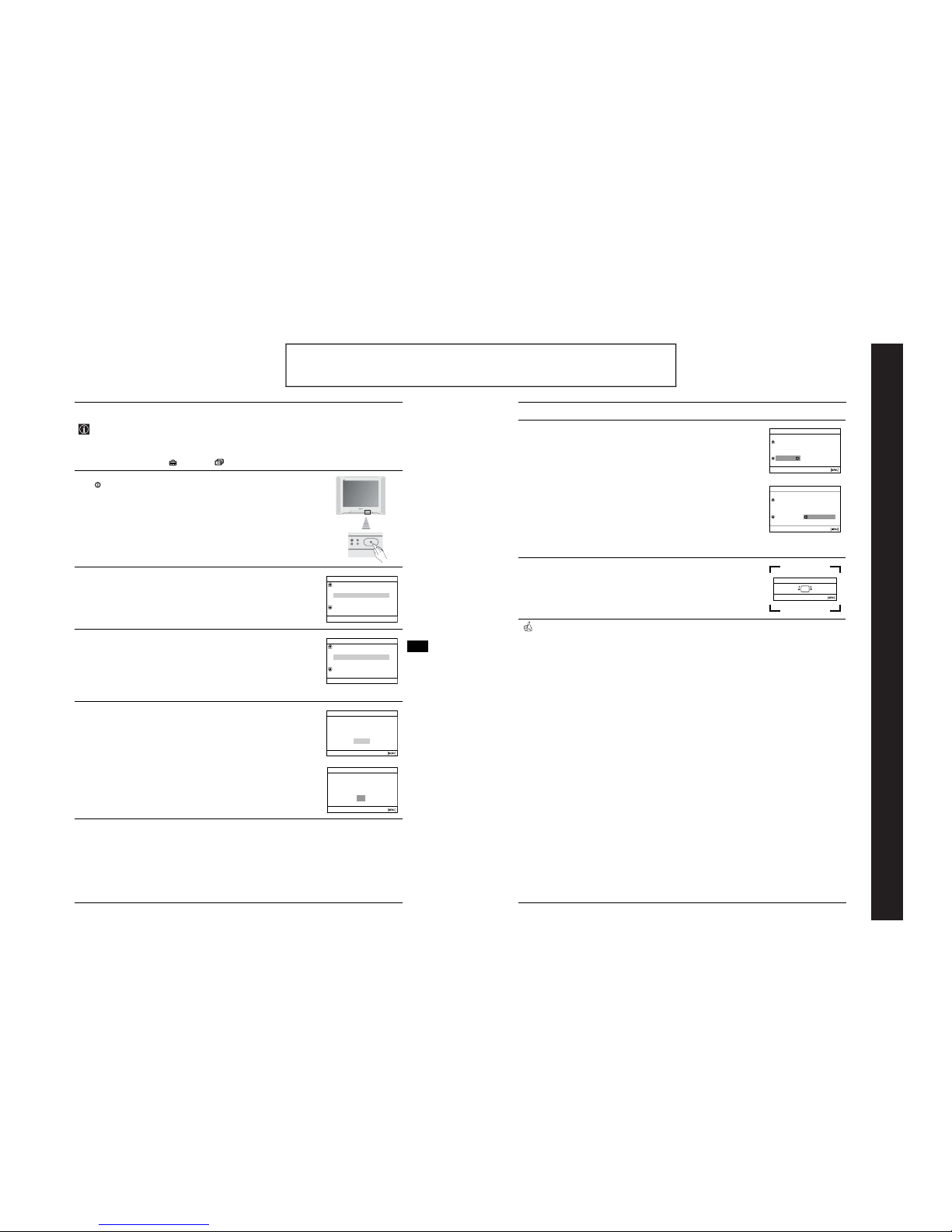
First Time Operation
Switching on the TV and Automatically Tuning
5
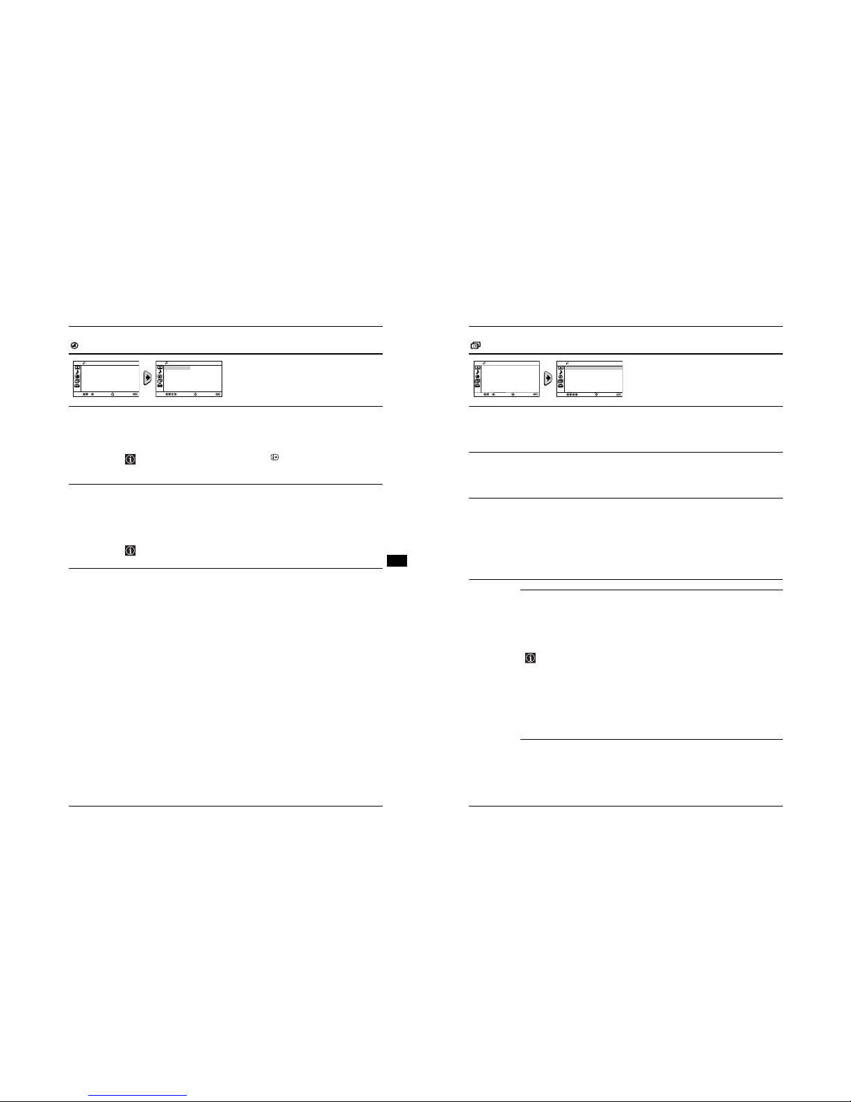
After all available channels are captured and stored, the Programme
Sorting menu appears automatically on the screen enabling you to change
the order in which the channels appear on the screen.
a)
If you wish to keep the broadcast channels in their tuned order, press
MENU.
b)
If you wish to store the channels in a different order:
1 Press the V or v button to select the programme number with the
channel (TV Broadcast) you wish to rearrange, then press the OK
button.
2 Press the V or v button to select the new programme number position
for your selected channel (TV Broadcast), then press the OK button.
3 Repeat steps b)1 and b)2 if you wish to change the order of the other
channels.
6
Because of the earth’s magnetism, the picture might slant. The Picture
Rotation menu allows you to correct the picture slant if it is necessary.
a)
If it is not necessary, press the OK button.
b)
If it is necessary, press the V or v button button to correct any slant of
the picture. Finally press the OK button to store.
Your TV is now ready for use.
Programme Sorting
Programme:
Select channel
Confirm [t
]
Select
[
–
2+
]
Exit
TVE
TVE2
TV3
04 C33
01
02
03
Programme Sorting
Programme:
Select new position
Confirm [t
]
Select
[
–
2+
]
Exit
01 TVE
02 TVE2
03 TV3
04 C33 03 TV3
Picture Rotation
Confirm [t
]
End
Select
[
–
2+
]
[2+
]
[
–
2
]
First Time Operation
7
Switching on the TV and Automatically Tuning
GB
The first time you switch on your TV, a sequence of menu screens appear on the TV enabling you to:
1) choose the language of the menu screen, 2) choose the country in which you wish to operate the
TV, 3) search for and store all available channels (TV Broadcasts), 4) change the order in which the
channels (TV Broadcasts) appear on the screen and 5) adjust the picture slant.
However, if you need to change any of these settings at a later date, you can do that by selecting the
appropriate option in the (Set Up) or (Chann el Set Up) menu.
1
Connect the TV plug to the mains socket (220-240V AC, 50Hz). Press the
on/off button on the TV set to turn on the TV.
The first time you switch on the TV, a Language menu appears
automatically on the TV screen.
2
Press the v or V button on the remote control to select the language, then
press the OK button to confirm your selection. From now on all the menus
will appear in the selected language.
3
The Country menu appears automatically on the TV screen. Press the V or
v
button to select the country in which you will operate the TV set, then
press the OK button to confirm your selection.
• If the country in which you want to use the TV set do es not appear in
the list, select “-” instead of a country.
• In order to avoid wrong teletext characters for Cyrillic languages we
recommend you select Russia as the country if your own country
does not appear in the list.
4
Ensure the aerial is connected as instructed (see page 6), then press the
OK button to confirm. The TV automatically starts searching and storing all
available broadcast channels for you.
• This procedure could take some minutes. Please be patient and do
not press any buttons, otherwise automatic tuning will not be
completed.
• If no channels were found during the auto tuning process, a new
menu appears automatically on the screen asking you connect the
aerial. Please connect the aerial (see page 6) and press the OK
button. The auto tuning process will start again.
Language
Svenska
English
Nederlands
Français
Select language
Norsk
Confirm [t
]
Select
[
–
2+
]
Country
Schweiz/Suisse/Svizzera
Italia
Select Country
Norge
Sverige
–
Confirm [t
]
Select
[
–
2+
]
Do you want to start automatic
First please connect aerial
tuning?
No
Initial Set Up
Yes
Confirm [t
]
Select
[
–
2+
]
End
Auto Tuning
No channel found
Please connect aerial
OK
Confirm [t
]
End
continued...
The operating instructions mentioned here are partial abstracts from the ‘Operating
Instruction Manual’. The page numbers of the ‘Operating Instruction Manual’ remain
as in the manual.
SECTION 1 GENERAL
- 9 -
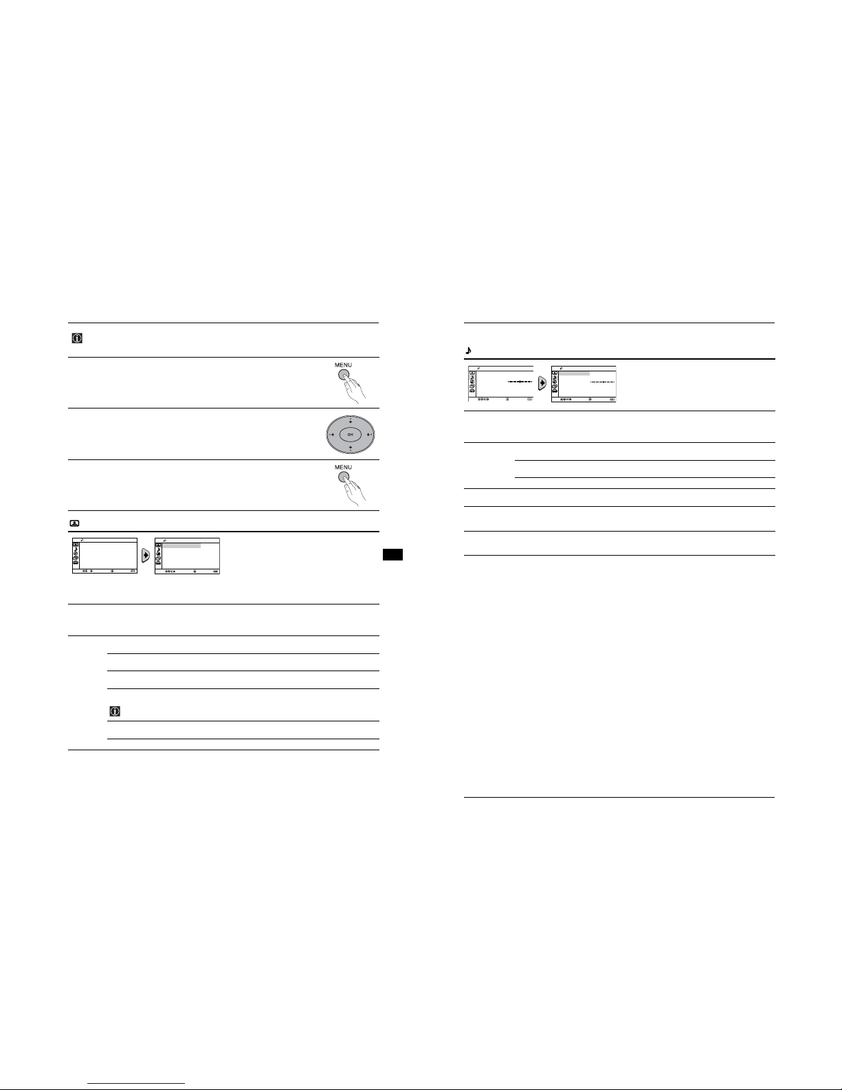
Menu System
9
Introducing and Using the Menu System
GB
Your TV uses an on-screen menu system to guide you through the operations. Use the following
buttons on the Remote Control to operate the menu system:
1
Press MENU to switch the menu on.
2
• To highlight the desired menu or option, press V or v button
.
• To enter to the selected menu or option, press b.
• To return to the last menu or option, press B
.
• To alter the settings of your selected option, press V/v/B or b.
• To confirm and store your selection, press the OK button.
3
Press MENU to remove the menu from the screen.
Picture
The “Picture” menu allows you to alter the picture
adjustments.
To do this:
After selecting the item you want to alter, press b,
then press v/V/B or b repeatedly to adjust and finally
press
OK
to store the new adjustments.
This menu also allows you to customise the picture
mode based on the programme you are watching:
Mode Live (for enhanced picture contrast and sharpness).
Movie (for a finely detailed picture).
Game (for a picture from a game).
Personal (for your own custom settings).
Picture
Adjustment
Contrast Press v or B to reduce picture contrast.
Press V or b to enhance picture contrast.
Brightness Press v or B to darken the picture.
Press V or b to brighten the picture.
Colour Press v or B to decrease colour intensity.
Press V or b to increase colour intensity.
Hue Press v or B to decrease the green tones.
Press V or b to increase the green tones.
Hue can only be adjusted for NTSC colour signal (e.g. USA video tapes).
Sharpness Press v or B to soften the picture.
Press V or b to sharpen the picture.
Reset Select
OK
to reset the picture to the factory preset levels.
Intelligent
Picture
On/Off Select to optimize the picture quality.
E.g. reduce noise level when signal is weak.
If any changes are made to “Picture Adjustment”, “Mode” will switch automatically to “Personal” and the
new settings will be stored as “Personal”.
Picture
Intelligent Picture:
On
Picture Adjustment
Mode: Live
Confirm
Select
End
Picture
Intelligent Picture:
On
Picture Adjustment
Mode: Live
Confirm
Select
End
10
Menu System
Introducing and Using the Menu System
Sound
The “Sound” menu allows you to alter the sound
adjustments.
To do this:
After selecting the item you want to alter, press b,
then press v/V/B or b repeatedly to adjust and finally
press
OK
to store it.
Mode Dynamic (dynamic and clear sound that emphasizes both the low and high tones).
Drama (sound that emphasizes voice and high tones).
Soft (soft, natural and relaxing sound).
Personal (flat and smooth sound that can be customized by users).
Sound
Adjustment
Treble Press v or B to decrease higher-frequency sounds.
Press V or b to increase higher-frequency sounds.
Bass Press v or B to decrease lower-frequency sounds.
Press V or b to increase lower-frequency sounds.
Reset Select
OK
to reset the sound to the factory preset.
Balance Press v or B to emphasize the left speaker.
Press V or b to emphasize the right speaker.
Auto Volume On/Off
Volume level of the channels will stay the same, independent of the broadcast signal (e.g.
in the case of advertisements).
Sound Effect Off (normal).
Spatial (simulated stereo-like sound quality for mono programmes).
Surround (add surround effect to stereo programmes).
Select
Confirm
End
Sound
Mode:
Balance
Dynamic
Auto Volume: Off
Sound Adjustment
Sound Effect: Off
Select
Confirm
End
Sound
Mode:
Balance
Dynamic
Auto Volume: Off
Sound Adjustment
Sound Effect: Off
- 10 -
Menu System
11
Introducing and Using the Menu System
GB
Timer
The “Timer” menu allows you to alter the timer
adjustments.
Sleep Timer The “Sleep Timer” option in the “Timer” menu allows you to select a ti me period for the TV
to switch itself automatically into the standby mode.
To do this:
After selecting the option, press b, then press V or v to set the time period delay (max. of
1 hour 30 minutes) and finally press
OK
to store.
• While watching the TV, you can press the button on the remote control to
display the time remaining.
• One minute before the TV switches itself into standby mode “TV will turn off soon”
is displayed on the TV screen automatically.
On Timer The “On Timer” option in the “Timer” menu allows you to select a time period for the TV to
switch itself automatically on from standby mode.
To do this:
After selecting the option, press b, then press V or v to set the time period delay (max. of
12 hours) and finally press
OK
to store. Finally press the standby button I/1 on the remote
control. After the selected length of time, the TV switches on automatically and “On Timer”
will appear on the screen.
• Any loss of power will cause these settings to be cleared.
• If no buttons are pressed for more than one hour after the TV is turned on using
the “On Timer”, the TV automatically goes into standby mode.
Timer
On Timer:
Sleep Timer: Off
Off
Select
Confirm
End
Timer
On Timer:
Sleep Timer: Off
Off
Select
Confirm
End
12
Menu System
Introducing and Using the Menu System
Channel Set Up
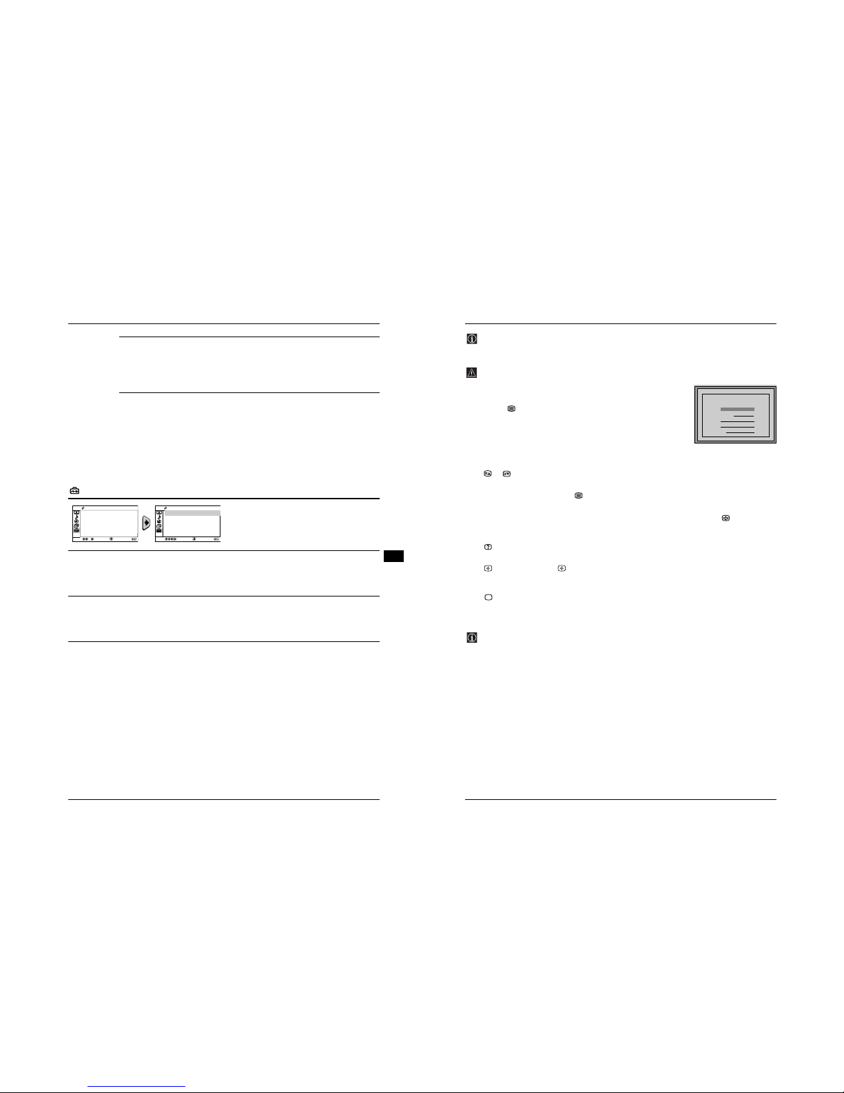
The “Channel Set Up” menu allows you to preset
channels on this TV.
Auto Tuning The “Auto Tu ning” option in the “Channel Set Up” menu allows you to automatically
search and store all available TV channels.
To do this:
After selecting the option, press b, and then proceed in the same way as in step 4 of the
section “Switching On the TV and Automatically Tuning” (see page 7).
Programme
Sorting
The “Programme Sorting” option in the “Channel Set Up” menu allows you to change the
order in which the channels (TV broadcast) appear on the screen.
To do this:
After selecting the option, press b, and then proceed in the same way as in step 5b) of the
section “Switching On the TV and Automatically Tuning” (see page 8).
Programme
Labels
The “Programme Labels” option in the “Channel Set Up” menu allows you to name a
channel using up to five characters (letters or numbers).
To do this:
1 After selecting the option, press b. Press V or v to select the programme number
with the channel you wish to name, then press
OK
.
2 Press b. With the first element of the label column highlighted, press V or v to
select a letter or number (select “-” for a blank), then press b to confirm this
character. Select the other four characters in the same way. finally press
OK
to
store.
Manual
Programme
Preset
The “Manual Programme Preset” option in the “Channel Set Up” menu allows you to:
a) Preset channels or a video input source one by one to the programme of your
choice.
To do this:
1 After selecting the “Manual Programme Preset” option, press b. Press V or v to
select the Programme option and press b. Press V or v to select a programme
number on which you want to preset the channel (for VCR, select programme
number “0”), then press B.
The following option is only available depending on the country you have selected
in the “Language/Country” menu.
2 After selecting the System option, press b. Press V or v to select the appropriate
broadcast system (B/G or D/K) until the correct sound is heard, then press
OK
.
3 After selecting the Channel option, press b. Press V or v to select the channel
tuning (C for terrestrial channels or S for cable channels). Next press b. After that,
press the number buttons to directly enter the channel number of the TV Broadcast.
If you do not know the channel number, press V or v to search for it. When you
tune the desired channel, press
OK
twice to store.
Repeat all the above steps to tune and store more channels.
Select
End
Channel Set Up
Programme Labels
Manual Programme Preset
Programme Sorting
Auto Tuning
Confirm
Select
End
Channel Set Up
Programme Labels
Manual Programme Preset
Programme Sorting
Auto Tuning
Confirm
continued...
- 11 -
Menu System
13
Introducing and Using the Menu System
GB
b) Normally the automatic fine tuning (AFT) will give the best possible picture,
however you can manually fine tune the TV to obtain a better picture if the picture is
distorted.
To do this:
While watching the channel (TV Broadcast) you wish to fine tune, select the AFT option
and press b. Next press V or v to adjust the fine tuning between -15 and +15. Finally
press
OK
twice to store.
c) Skip any unwanted programme numbers when they are selected with the
PROG +/- button.
To do this:
Highlighting the Programme option, press PROG +/- to select the programme number
you want to skip. When the programme you want to skip appears on the screen, select the
Skip option and press b. Next press V or v to select Yes. Finally press
OK
twice to
confirm and store.
To cancel this function afterwards, select No instead of Yes in the step above.
Set Up
The “Set Up” menu allows you to alter various options
on this TV.
Language/
Country
The “Language/Country” option in the “Set Up” menu allows you to select the language
that the menus are displayed in.
To do this:
After selecting the option, press b, and then proceed in the same way as in steps 2 and 3
of the section “Switching On the TV and Automatically Tuning” (see page 7).
Picture
Rotation
Because of the earth’s magnetism, the picture might slant. In this case, you can correct
the picture slant by using the option “Picture Rotation” in the “Set Up” menu.
To do this:
After selecting the option, press b. Press B or b (V or v) to correct any slant of the picture.
Finally press
OK
to store.
RGB Centring When connecting an RGB source, such as a “PlayStation 2”, you may need to readjust the
horizontal position of the picture. In that case, you can readjust it through the “RGB
Centring” option in the “Set Up” menu.
To do this:
While watching an RGB source, select the “RGB Centring” option and press b. Press V or
v to adjust the picture between -10 and +10. Finally press
OK
to confirm and store.
Select
End
Set Up
RGB Centring: 0
Picture Rotation
Language/Country
Confirm
Select
End
Set Up
RGB Centring: 0
Picture Rotation
Language/Country
Confirm
14
Teletext
Teletext
TELETEXT
Index
Programme
News
Sport
Weather
25
153
101
98
TELETEXT
Index
Programme
News
Sport
Weather
25
153
101
98
TELETEXT
Index
Programme
News
Sport
Weather
25
153
101
98
TELETEXT
Index
Programme
News
Sport
Weather
25
153
101
98
TELETEXT
Index
Programme
News
Sport
Weather
25
153
101
98
TELETEXT
Index
Programme
News
Sport
Weather
25
153
101
98
TELETEXT
Index
Programme
News
Sport
Weather
25
153
101
98
TELETEXT
Index
Programme
News
Sport
Weather
25
153
101
98
Teletext is an information service transmitted by most TV stations. The index page of the teletext service
(usually page 100) gives you information on how to use the service. To operate teletext, use the remote
control buttons as indicated below.
Be sure to use a channel (TV Broadcast) with a strong signal, otherwise Teletext errors may occur.
To switch on Teletext:
After selecting the TV channel which carries the teletext service you wish
to view, press .
To select a Teletext page:
Input the 3 digits of the page number, using the numbered buttons.
• If you have made a mistake, retype the correct page number.
• If the counter on the screen continues searching, it is because the page is not
available. In that case, input another page number.
To access the next or preceding page:
Press or .
To superimpose teletext onto the TV:
Whilst you are viewing teletext, press . Press again to cancel Teletext mode.
To freeze a teletext page:
Some Teletext pages have sub-pages which follow on automatically. To stop them, press . Press again to
cancel the freeze.
To reveal concealed information (e.g., answer to a quiz):
Press . Press again to conceal the information.
To enlarge the Teletext display:
Press . Each time you press , the Teletext display changes as follows: Enlarge upper halftEnlarge
lower halftNormal size.
To Switch Off Teletext:
Press .
Fastext
The Fastext service lets you access pages with one push of a button.
While you are in Teletext mode and Fastext is broadcast, a colour coded menu appears at the bottom of
the teletext page. Press the coloured buttons (red, green, yellow or blue) to access the corresponding
page.
- 12 -
Sony Corporation Printed in Slovakia
KV-29SE10K
2-636-974-11(1)
263697411
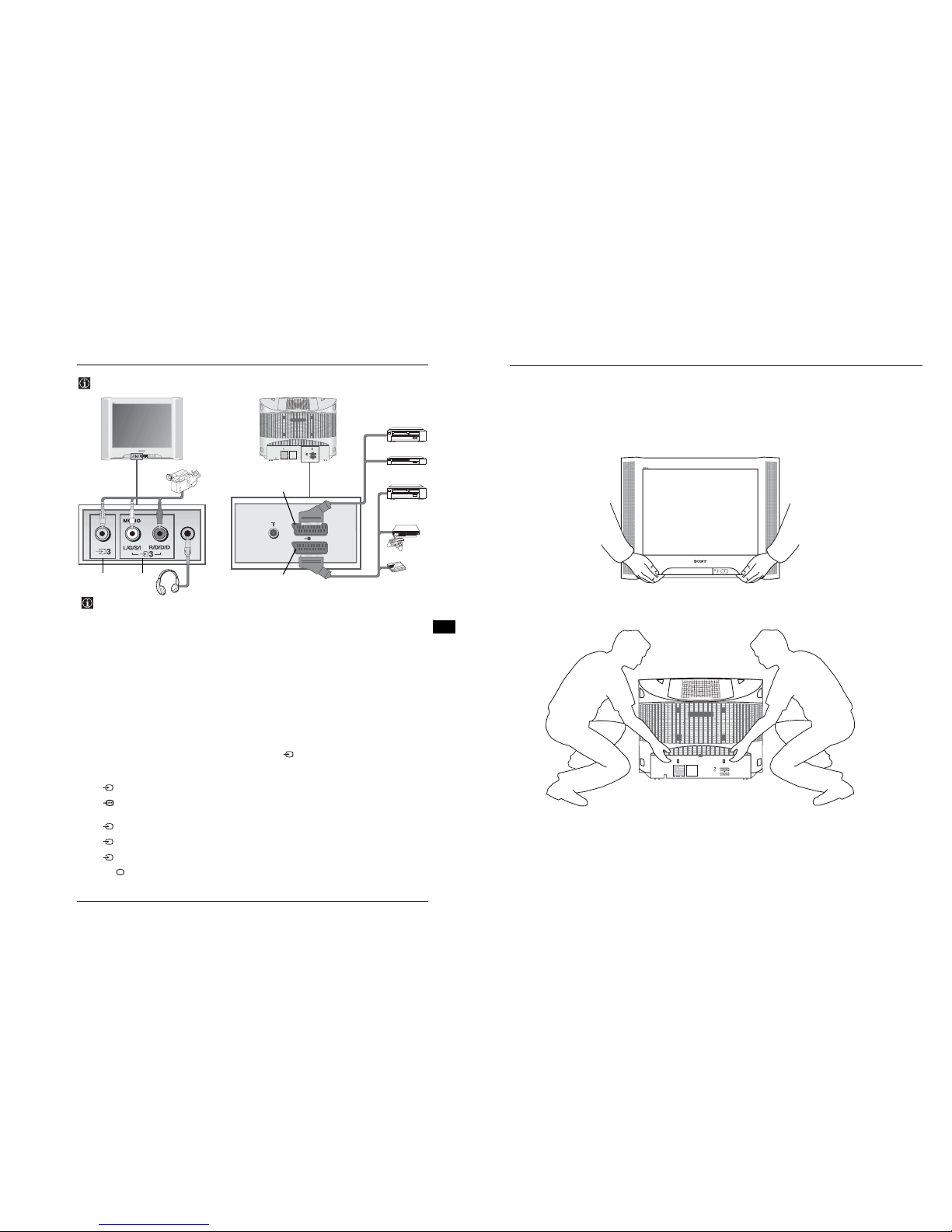
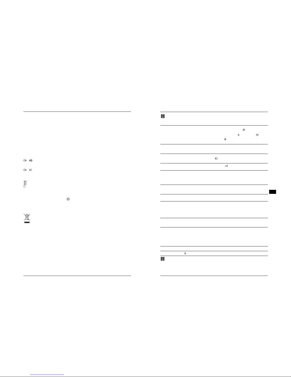
Lifting the TV Set
Additional Information
15
Connecting Optional Equipment
GB
Using the following instructions you can connect a wide range of optional equipment to your TV set
(connecting cables are not supplied).
D
DVD
Decoder
VCR
“PlayStation 2”
*
*
“PlayStation 2” is a product of Sony
Computer Entertainment, Inc.
*
“PlayStation 2” is a trademark of Sony
Computer Entertainment, Inc.
When you connect the headphones,
the TV speakers will automatically be
muted.
C
A
8mm/Hi8/
DVC
camcorder
DVD/VCR
B
Connecting a VCR:
To connect a VCR, please refer to the section “Connecting an aerial and VCR” of this instruction manual. We
recommend you connect your VCR using a Scart lead. If you do not have a Scart lead, tune in the VCR test
signal to the TV programme number “0” by using the “Manual Programme Preset” option. (for details of how
to manually programme these presets, see page 13, step a).
Refer to your VCR instruction manual to find out the output channel of your VCR.
To connect a “PlayStation 2”, please refer to the instruction manual of “PlayStation 2”.
Using optional Equipment
1
Connect your equipment to the designated TV socket, as indicated in the previous page.
2
Switch on the connected equipment.
3
To watch the picture from the connected equipment, press repeatedly until the correct input symbol
appears on the screen.
Symbol
1
1
2
2
3
Input Signals
• Audio/video input signal through the Scart connector C.
• RGB input signal through the Scart connector C. This symbol appears only if a RGB
source has been connected.
• Audio/video input signal through the Scart connector D.
• S Video Input signal through the Scart connector D.
• Video input signal through the phono socket A and Audio input signal through B.
4
Press button on the remote control to return to the normal TV picture.
S
- 13 -
16 Additional Information
Specifications
TV system:
Depending on your country selection:
B/G/H, D/K
Colour system:
PAL, SECAM
NTSC 3.58, 4.43 (only Video In)
Channel Coverage:
VHF: E2-E12
UHF: E21-E69
CATV: S1-S20
HYPER: S21-S41
D/K R1-R12, R21-R69
Picture Tube:
Flat Display FD Trinitron
Rear Terminals:
1/ 21-pin scart connector (CENELEC
standard) including audio/video input,
RGB input, TV audio/video output.
2/ 21-pin Scart connector (CENELEC
standard) including audio / video input, S
video input, monitor audio / video output.
Front Terminals:
3 video input – phono jack
3 audio input – phono jacks
headphones jack
S
Sound Output:
2 x 12 W (music power)
2 x 6 W (RMS)
Power Consumption:
130 W
Standby Power Consumption:
< 1 W
Dimensions (w x h x d):
Approx. 776 x 595 x 521 mm.
Weight:
Approx. 45 Kg.
Accessories supplied:
1 Remote Control (RM-EA005)
2 Batteries (IEC designated, AA/R6 size)
Other features:
• Teletext, Fastext, TOPtext
• Sleep Timer
•On Timer
• TV system Autodetection
Design and specifications are subject to change without notice
Ecological Paper - Totally Chlorine Free
Disposal of Old Electrical & Electronic Equipment (Applicable in the European Union and other
European countries with separate collection systems)
This symbol on the product or on its packaging indicates that this product shall not be treated as
household waste. Instead it shall be handed over to the applicable collection point for the recycling of
electrical and electronic equipment. By ensuring this product is disposed of correctly, you will help
prevent potential negative consequences for the environment and human health, which could
otherwise be caused by inappropriate waste handling of this product. The recycling of materials will
help to conserve natural resources. For more detailed information about recycling of this product,
please contact your local Civic Office, your household waste disposal service or the shop where you
purchased the product.
Additional Information 17
Troubleshooting
GB
Here are some simple solutions to problems which may affect the picture and sound.
Problem Solution
No picture (screen is dark), and no sound. • Check the aerial connection.
• Plug the TV in and press the button on the front of
the TV.
• If the standby indicator is on press the button
on the remote control.
• Press the button on the front of the TV to switch off
the TV for about 5 seconds, then switch it on again.
Poor or no picture (screen is dark), but good
sound.
• Using the menu system, select the “Picture
Adjustment” menu and select “Reset” to return to the
factory settings (see page 9).
No picture or menu information from equipment
connected to the Scart socket.
• Check that the optional equipment is on, and press
repeatedly on the remote control until the correct
input symbol is displayed on screen (see page 15).
Good picture, no sound. • Press the + button on the remote control.
• Check the Headphones are not connected.
Good picture, distorted sound. • Using the menu system, enter the “Manual
Programme Preset” option in the “Channel Set Up”
menu and select the appropriate TV system in the
“System” menu until the correct sound is heard (see
page 12).
No colour on colour programmes. • Using the menu system, select the “Picture
Adjustment” menu and select “Reset” to return to the
factory settings (see page 9).
Distorted picture when changing programmes or
selecting Teletext.
• Turn off any equipment connected to the Scart
connectors on the rear of the TV.
Wrong characters appear when viewing teletext. • Using the menu system, enter the “Language/
Country” option in the “Set Up” menu and select the
country in which you are operating the TV set. For
Cyrillic languages, we recommend to select Russia in
the case that your own country does not appear in the
list (see page 13).
Picture slanted. • Using the menu system, select the “Picture Rotation”
option in the “Set Up” menu to correct the picture slant
(see page 13).
Noisy picture when viewing a TV channel. • Using the menu system, select the “Manual
Programme Preset” menu and adjust Fine Tuning
(AFT) to obtain better picture reception (see page
13).
• Using the menu system, select the “Intelligent
Picture” option in the “Picture” menu and select “On”
to reduce the noise in the picture (see page 9).
Remote control does not function. • Replace the batteries.
The standby indicator on the TV flashes red. • Contact your nearest Sony service centre.
In case of problems, have your TV serviced by qualified personnel. Never open the casing yourself.
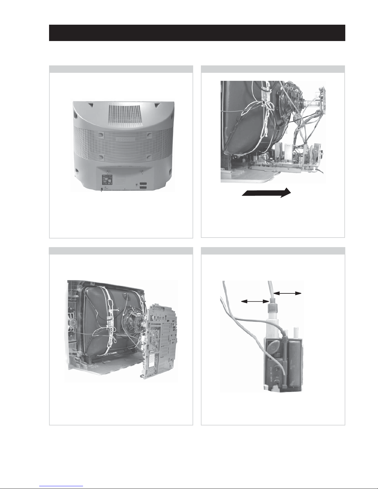
- 14 -
SECTION 2 DISASSEMBLY
2-1. Rear Cover Removal
Remove the rear cover fixing screws indicated and pull the
rear cover backwards away from the set.
=>
=>
=>
=>
=>
=>
2-3. Service Position
Position the chassis as indicated to access the solder side of
the A PWB.
2-4. Wire Dressing
Ensure that wires do not touch heatsinks and high temperature
hotspots. All wires must be kept at a minimum distance of
20mm away from the EHT lead
20mm
20mm
=>
To remove lift the main bracket rear slightly and slide the
chassis away from the beznet. Ensure that the interconnecting
leads are released from their purse locks to prevent damage
being caused.
2-2. Chassis Removal and Refitting

- 15 -
How to handle the Anode-Cap
1. To prevent damaging the surface of the anode-cap do not use
sharp materials.
2. Do not apply too great a pressure on the rubber, as this may cause
damage to the anode connector.
3. A metal fitting called a shatter hook terminal is fitted inside the
rubber cap.
4. Do not turn the rubber foot over excessively, this may cause
damage if the shatter hook sticks out.
Removal of the Anode-Cap
2-5. Picture Tube Removal
WARNING:
BEFORE REMOVING
THE ANODE CAP
High voltage remains in the CRT even
after the power is disconnected. To
avoid electric shock, discharge CRT
before attempting to remove the anode
cap. Short between anode and CRT
coated earth ground strap.
Coated Earth
Ground Strap
1. Discharge the anode of the CRT and remove the anode cap.
2. Unplug all interconnecting leads from the Deflection yoke, neck
assy, degaussing coils and CRT grounding strap.
3. Remove the C Board from the CRT.
4. Remove the chassis assembly.
5. Loosen the Deflection yoke fixing screw and remove.
6. Place the set with the CRT face down on a cushion and remove
the Degaussing Coil holders.
7. Remove the Degaussing Coils.
8. Remove the CRT grounding strap and spring tensioners.
9. Unscrew the four CRT fixing screws [ located on each CRT
corner ] and remove the CRT.
[Take care not to handle the CRT by the neck.]
Anode button
a
REMOVAL PROCEDURE.
Turn up one side of the rubber cap in
the direction indicated by the arrow a
1
2 Using a thumb pull up the rubber cap
firmly in the direction indicated by the
arrow b
3 When one side of the rubber cap is
separated from the anode button, the
anode-cap can be removed by turning
up the rubber cap and pulling it up in
the direction of the arrow c
b
b
c
2
4
7
9
5
8
3
6
1
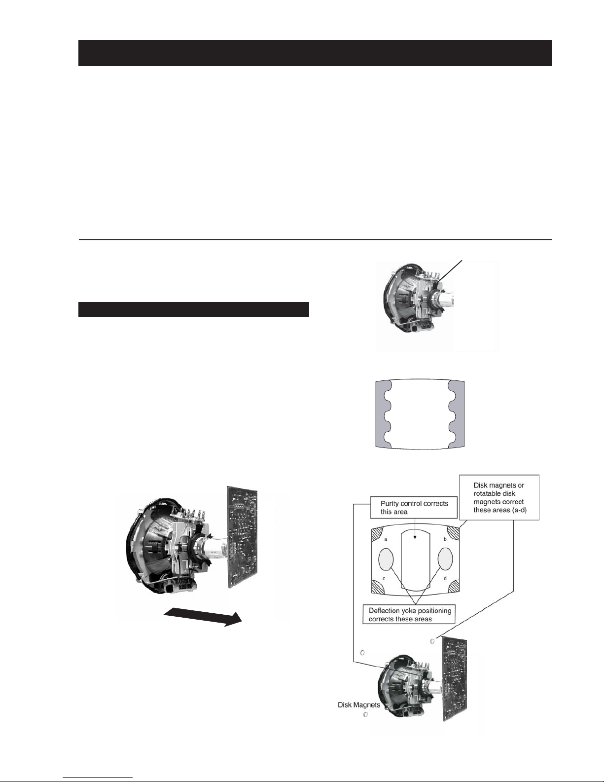
- 16 -
GREEN
BLUE
RED
Preparation:
1. In order to reduce the influence of geomagnetism on the
set’s picture tube, face it in an easterly or westerly direction.
2. Switch on the set’s power and degauss with the degausser.
1. Input an all white signal from the pattern generator. Set the
Contrast and Brightness to normal.
2. Set the pattern generator raster signal to a Red raster.
3. Move the deflection yoke to the front and adjust with the
purity control so that the Red is at the centre and the Blue
and Green take up equally sized areas on each side of the
screen. [See Fig.3-1 - 3-3].
4. Move the deflection yoke backwards and adjust so that the
entire screen becomes Red. [See Fig.3-1]
5. Switch the raster signal to Blue, then to Green and verify
the condition.
6. When the position of the deflection yoke has been
determined, fasten the deflection yoke with the screws.
7. If the beam does not land correctly in all the corners, use a
magnet to correct it. [See Fig.3-4]
• When complete readjustment is necessary or a new picture
tube is installed, carry out the following adjustments.
• Unless there are specific instructions to the contrary, carry
out these adjustments with the rated power supply.
• Unless there are specific instructions to the contrary, set the
controls and switches to the following settings :
Contrast .................... 80% [or remote control normal]
Brightness ................... 50%
Carry out the adjustments in the following order :
3-1. Beam Landing.
3-2. Convergence.
3-3. Focus.
3-4. White Balance.
Note : Test equipment required.
1. Color bar/pattern generator.
2. Degausser.
3. Oscilloscope.
4. Digital multimeter.
5. DC Power Supply
Caution :
High voltages are present on the Deflection yoke terminals
- take care when handling the Deflection yoke whilst carrying
out adjustments.
Fig.3-4
Fig. 3-1.
Fig. 3-3.
Fig. 3-2.
Purity
SECTION 3 SET-UP ADJUSTMENTS
3-1. Beam Landing
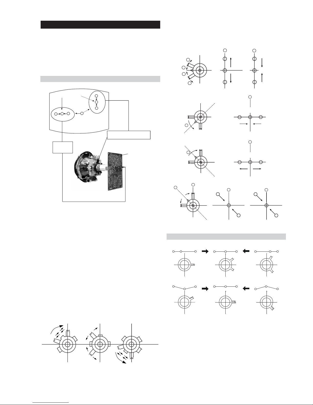
- 17 -
4. If the V.STAT magnet is moved in the direction of the (a)
and (b) arrows, the Red, Green and Blue points move as
indicated below.
1. [Moving horizontally], adjust the H.STAT control so that
the Red, Green and Blue points are on top of each other at
the centre of the screen.
2. [Moving vertically], adjust the V.STAT magnet so that the
Red, Green and Blue points are on top of each other at the
centre of the screen.
3. If the H.STAT variable resistor is unable to bring the Red,
Green and Blue points together at the centre of the screen,
adjust the horizontal convergence with the H.STAT variable
resistor and the V.STAT magnet in the manner indicated
below.
[In this case, the H.STAT variable resistor and the V.STAT
magnet influence each other].
The movement of the magnets interact with each other and so
the respective dot position should be monitored while carrying
out this adjustment.
Use the H.STAT VR to adjust the Red, Green and Blue dots so
that they coincide at the centre of the screen
(by moving the dots in the horizontal direction).
GBR
GBR
GBR
G
B
R
GBR
G
B
R
3-2. Convergence
Operation of the BMC (Hexapole) magnet.
Preparation:
• Before starting this adjustment, adjust the focus, horizontal
size and vertical size.
• Minimize the Brightness setting.
• Input a dot pattern from the pattern generator.
Horizontal and Vertical Static Convergence
Center dot
R
G
B
R
G
B
C Board
RV750 (H STAT)
H STAT Convergence
(on mount side)
H STAT
convergence
control
V.STAT Vertical Static Magnet
Fig.3-5
• Tilt the V.STAT magnet and adjust the static convergence by
opening or closing the V.STAT magnet.
B
G
R
B
G
R
a
a
b
b
a
b
B
G
R
a
a
B
G
R
b
b
B
G
R
a
b
R
G
B
b
a
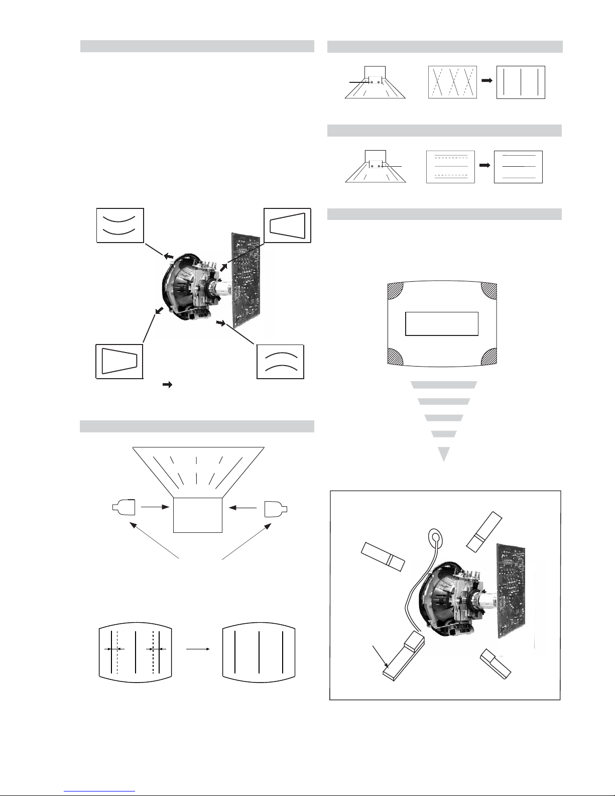
- 18 -
a
b
d
Permalloy Assy
X-4387-214-1
c
Install the permalloy assembly
for the area that needs correcting.
Convergence adjustment with permalloy
Tilt Direction
If you are unable to adjust the corner convergence properly,
this can be corrected with the use of permalloy magnets.
HTIL correction can be performed by adding a TLH correction
assembly to the Deflection yoke.
HTIL Adjustment
YCH Adjustment
TLV Adjustment
Geometry Adjustment.
Preparation:
Before starting this adjustment, adjust the horizontal and
vertical static convergence.
1. Remove the deflection yoke spacer.
2. Tilt the deflection yoke as indicated in the figure below and
optimise the geometry.
Tilting the DY Up and Down will balance the upper and
lower pin adjustment.
Tilting the DY Left and Right will balance the H-Trap
adjustment.
3. Re-install the deflection yoke spacer.
+
YCH VR
Deflection Yoke
+
+
Deflection Yoke
+
TLV VR
Screen Corner Convergence
TLH pieces
Deflection Yoke
a-d: screen-corner
convergence defect
a
b
c
d
 Loading...